WO2019189155A1 - 測定装置 - Google Patents
測定装置 Download PDFInfo
- Publication number
- WO2019189155A1 WO2019189155A1 PCT/JP2019/012816 JP2019012816W WO2019189155A1 WO 2019189155 A1 WO2019189155 A1 WO 2019189155A1 JP 2019012816 W JP2019012816 W JP 2019012816W WO 2019189155 A1 WO2019189155 A1 WO 2019189155A1
- Authority
- WO
- WIPO (PCT)
- Prior art keywords
- sensor
- support member
- limb
- ankle
- expansion
- Prior art date
Links
Images


Classifications
-
- A—HUMAN NECESSITIES
- A61—MEDICAL OR VETERINARY SCIENCE; HYGIENE
- A61B—DIAGNOSIS; SURGERY; IDENTIFICATION
- A61B5/00—Measuring for diagnostic purposes; Identification of persons
- A61B5/103—Detecting, measuring or recording devices for testing the shape, pattern, colour, size or movement of the body or parts thereof, for diagnostic purposes
- A61B5/107—Measuring physical dimensions, e.g. size of the entire body or parts thereof
- A61B5/1073—Measuring volume, e.g. of limbs
-
- A—HUMAN NECESSITIES
- A61—MEDICAL OR VETERINARY SCIENCE; HYGIENE
- A61B—DIAGNOSIS; SURGERY; IDENTIFICATION
- A61B2562/00—Details of sensors; Constructional details of sensor housings or probes; Accessories for sensors
- A61B2562/02—Details of sensors specially adapted for in-vivo measurements
- A61B2562/0261—Strain gauges
-
- A—HUMAN NECESSITIES
- A61—MEDICAL OR VETERINARY SCIENCE; HYGIENE
- A61B—DIAGNOSIS; SURGERY; IDENTIFICATION
- A61B5/00—Measuring for diagnostic purposes; Identification of persons
- A61B5/0002—Remote monitoring of patients using telemetry, e.g. transmission of vital signals via a communication network
- A61B5/0015—Remote monitoring of patients using telemetry, e.g. transmission of vital signals via a communication network characterised by features of the telemetry system
- A61B5/0024—Remote monitoring of patients using telemetry, e.g. transmission of vital signals via a communication network characterised by features of the telemetry system for multiple sensor units attached to the patient, e.g. using a body or personal area network
-
- A—HUMAN NECESSITIES
- A61—MEDICAL OR VETERINARY SCIENCE; HYGIENE
- A61B—DIAGNOSIS; SURGERY; IDENTIFICATION
- A61B5/00—Measuring for diagnostic purposes; Identification of persons
- A61B5/48—Other medical applications
- A61B5/4869—Determining body composition
- A61B5/4875—Hydration status, fluid retention of the body
- A61B5/4878—Evaluating oedema
-
- A—HUMAN NECESSITIES
- A61—MEDICAL OR VETERINARY SCIENCE; HYGIENE
- A61B—DIAGNOSIS; SURGERY; IDENTIFICATION
- A61B5/00—Measuring for diagnostic purposes; Identification of persons
- A61B5/68—Arrangements of detecting, measuring or recording means, e.g. sensors, in relation to patient
- A61B5/6801—Arrangements of detecting, measuring or recording means, e.g. sensors, in relation to patient specially adapted to be attached to or worn on the body surface
- A61B5/6813—Specially adapted to be attached to a specific body part
- A61B5/6828—Leg
-
- A—HUMAN NECESSITIES
- A61—MEDICAL OR VETERINARY SCIENCE; HYGIENE
- A61B—DIAGNOSIS; SURGERY; IDENTIFICATION
- A61B5/00—Measuring for diagnostic purposes; Identification of persons
- A61B5/68—Arrangements of detecting, measuring or recording means, e.g. sensors, in relation to patient
- A61B5/6801—Arrangements of detecting, measuring or recording means, e.g. sensors, in relation to patient specially adapted to be attached to or worn on the body surface
- A61B5/683—Means for maintaining contact with the body
- A61B5/6831—Straps, bands or harnesses
Definitions
- the present invention relates to a measuring device capable of measuring the amount of edema of the limb.
- Limb edema is known as one of the symptoms associated with diseases such as heart failure and liver failure, and it is important to understand the amount of edema of the limbs when diagnosing these diseases. is there.
- Patent Document 1 it is possible to measure the amount of edema of a limb by wrapping a long band around the limb and detecting the circumference of the limb based on the coupling position where the ends of the band are coupled to each other An apparatus is disclosed.
- Limb edema which occurs with diseases such as heart failure and liver failure, is known as indentation edema, in which when the limb is pressed, fluid accumulated in the pressed area of the limb escapes from the pressed area, resulting in an indentation at the pressed area. Yes. Therefore, when the edema that has occurred in the limb is an indentation edema, there is a possibility that the device as described in Patent Document 1 may cause the band to bite into the limb and generate an indentation, and an accurate amount of edema cannot be measured.
- the present invention has been made in view of the above circumstances, and an object of the present invention is to provide a measuring apparatus capable of more accurately measuring the amount of edema of a limb.
- a measuring device that achieves the above object is a measuring device capable of measuring the amount of edema of a limb, has a sheet shape, and is extendable and contractible in one direction intersecting the thickness direction.
- a sensor that can detect a change in electrical characteristics; and a support member that is attached to both ends of the sensor in the direction of expansion and contraction and surrounds the limb with the sensor in a mounted state.
- the measuring apparatus it is possible to measure the amount of edema of a limb while suppressing the formation of indentations in the limb by a sensor that can be stretched and can detect a change in electrical characteristics accompanying the stretching. Therefore, according to the present invention, it is possible to provide a measuring device that can more accurately measure the amount of edema of the limb.
- FIG. 2 is a cross-sectional view taken along line 2-2 in FIG.
- FIG. 3 is a cross-sectional view taken along line 3-3 in FIG. It is an arrow view from the arrow 4A direction of FIG. 1, Comprising: It is a figure which shows the mode during the initial setting. It is an arrow view from the arrow 4A direction of FIG. 1, Comprising: It is a figure which shows a mode in measurement.
- 1 is a block diagram of a measuring apparatus according to a first embodiment of the present invention. It is a top view which shows the measuring apparatus which concerns on 2nd Embodiment of this invention.
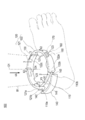
- FIG. 1 is a diagram for explaining the overall configuration of the measurement apparatus 100 according to the first embodiment.
- 2 to 5 are diagrams for explaining each part of the measuring apparatus 100 according to the first embodiment.
- the measuring apparatus 100 is mounted on an ankle B1 (corresponding to “limb”) of a patient with heart failure or liver failure, and measures the circumference of the ankle B1.
- the “peripheral length of the ankle B1” means the length of the ankle B1 around the long axis direction D1 of the foot.
- the wearer of the measuring apparatus 100 is not specifically limited to patients with heart failure, liver failure, or the like.
- the measurement apparatus 100 is a sheet-like sensor 110 having electrical conductivity, and a support member 120 that is attached to the sensor 110 and surrounds the limb body together with the sensor 110 when attached to the ankle B1.
- An adjustment member 130 that can adjust the length of the support member 120, a regulation member 140 that can regulate the length of the sensor 110, a communication unit 150 that can communicate with an external device, and a control unit that controls the operation of each unit. 160 and a power supply unit 170 capable of supplying power to each unit.
- each part of the measuring apparatus 100 will be described in detail.
- the senor 110 has conductivity and a sheet shape as shown in FIG.
- the sensor 110 is extendable in one direction intersecting with the thickness direction Y1 of the sensor 110 (hereinafter, referred to as “extension / contraction direction X1”), and electrical characteristics associated with extension / contraction in the extension / contraction direction X1. It is configured to detect changes in
- “extendable” means that the sensor 110 attached to the limb following the change in the amount of edema (volume of the limb) is elastically deformable in the extension / contraction direction X1. To do.
- the sensor 110 has a long sheet shape as shown in FIG.
- the expansion / contraction direction X1 of the sensor 110 corresponds to the longitudinal direction of the sensor 110 (the circumferential direction when the measuring device 100 is mounted on the ankle B).
- the shape of the sensor 110 is not particularly limited as long as it is a sheet shape.
- the sensor 110 may have a substantially square shape (that is, the sensor 110 does not have to be long).
- sensor 110 since sensor 110 is provided with a sheet shape, it can be easily expanded and contracted in one direction (stretching direction X1) intersecting thickness direction Y1. Therefore, the amount of edema of the ankle B1 can be measured by the sensor 110 while suppressing the formation of an impression on the ankle B1.
- the senor 110 includes a base material 111 having a long sheet shape and a pair of conductive layers 112a and 112b stacked in the thickness direction Y1 so as to sandwich the base material 111. And a pair of protective layers 113a and 113b stacked in the thickness direction Y1 so as to sandwich the pair of conductive layers 112a and 112b.
- the base material 111 is configured to be stretchable in the stretch direction X1.
- the base material 111 functions as a capacitor dielectric.
- the capacitance of the sensor 110 depends on the length and thickness of the sensor 110 in the expansion / contraction direction X1 (distance between the pair of conductive layers 112a and 112b). Therefore, by detecting the capacitance that is the electrical characteristic of the sensor 110, the amount of expansion / contraction of the sensor 110 in the expansion / contraction direction X1, that is, the amount of edema of the ankle B11 can be measured.
- the base material 111 is preferably made of a material mainly containing an elastomer material because it has excellent stretchability.
- the elastomer material used for the substrate 111 include natural rubber, isoprene rubber, nitrile rubber (NBR), ethylene propylene rubber (EPDM), styrene-butadiene rubber (SBR), butadiene rubber (BR), and chloroprene rubber (CR). ), Silicone rubber, fluorine rubber, acrylic rubber, hydrogenated nitrile rubber, urethane rubber, and combinations of two or more of these.
- the elastomer material used for the base material 111 urethane rubber is preferably used since it has a small permanent set and is excellent in adhesion to carbon nanotubes contained in each of the conductive layers 112a and 112b described later.
- the base material 111 is not limited to an elastic material, but also a dielectric filler (barium titanate, etc.), a plasticizer, a chain extender, a crosslinking agent, a catalyst, a vulcanization accelerator, an antioxidant, an aging agent. You may contain additives, such as an inhibitor and a coloring agent.
- Each of the conductive layers 112a and 112b is integrated with the base material 111, and is configured to be extendable and contractable in the expansion and contraction direction X1 integrally with the base material 111.
- Each of the conductive layers 112a and 112b is electrically connected to the control unit 160 via a transmitter (not shown) capable of AD conversion of the signal from the sensor 110.
- each of the conductive layers 112a and 112b is not particularly limited as long as it has conductivity and can be expanded and contracted integrally with the base material 111.
- the conductive layer 112a and 112b can be made of a material mainly containing carbon nanotubes.
- the carbon nanotubes used for each of the conductive layers 112a and 112b are not particularly limited. For example, single-walled carbon nanotubes, multi-walled carbon nanotubes, and a mixture of single-walled carbon nanotubes and multi-walled carbon nanotubes can be used.
- Each of the conductive layers 112a and 112b may contain a binder, a crosslinking agent, a vulcanization accelerator, a vulcanization aid, an anti-aging agent, a plasticizer, a softening agent, a colorant and the like in addition to the carbon nanotubes.
- the binder used for each of the conductive layers 112a and 112b is not particularly limited.
- butyl rubber ethylene propylene rubber, polyethylene, chlorosulfonated polyethylene, natural rubber, isoprene rubber, butadiene rubber, styrene / butadiene rubber, polystyrene
- examples include chloroprene rubber, nitrile rubber, polymethyl methacrylate, polyvinyl acetate, polyvinyl chloride, acrylic rubber, styrene-ethylene-butylene-styrene block copolymer, and combinations of two or more of these.
- the protective layers 113a and 113b are integrated with the conductive layers 112a and 112b, and are configured to be extendable and contractable in the expansion and contraction direction X1 integrally with the base material 111 and the pair of conductive layers 112a and 112b.
- the constituent material of the protective layers 113a and 113b for example, the same material as that of the base material 111 can be used.
- the sensor 110 is not particularly limited as long as the sensor 110 has conductivity and a sheet shape, can be expanded and contracted in one direction intersecting the thickness direction Y1, and can detect a change in electrical characteristics accompanying the expansion and contraction.
- the sensor 110 may be configured by the base material 111 and one conductive layer 112 a provided on one surface of the base material 111. In this case, as the sensor 110 expands and contracts, the distance between the carbon nanotubes in the conductive layer 112a changes, and the electrical resistance of the sensor 110 changes accordingly.
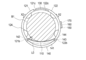
- the support member 120 is attached to both ends 110a and 110b in the expansion / contraction direction X1 of the sensor 110, and the ankle together with the sensor 110 in a wearing state in which the measuring device 100 is attached to the ankle B1. Surrounds B1. Therefore, the support member 120 fixes the sensor 110 to the ankle B1 in the mounted state, and pulls the both ends 110a and 110b in the expansion / contraction direction X1 of the sensor 110 and stretches the sensor 110 when edema occurs in the ankle B1. .
- the support member 120 is constituted by a long first belt member 121 and a second belt member 122 as shown in FIG.
- One end 121a of the first belt member 121 in the longitudinal direction X2 (circumferential direction in the mounted state) is connected to one end 110a of the expansion / contraction direction X1 of the sensor 110.
- One end 122a of the second belt member 122 in the longitudinal direction X2 is connected to the other end 110b of the sensor 110 in the expansion / contraction direction X1.
- the “end portion of the expansion / contraction direction X1 or the longitudinal direction X2” is not limited to the leading end of the expansion / contraction direction X1 or the longitudinal direction X2 of each member, but is constant from the leading end to the stretching direction X1 or the longitudinal direction X2. This range is also included.
- Projections 142 and 143 of a regulating member 140 described later can be inserted into one end 121a in the longitudinal direction X2 of the first belt member 121 and one end 122a in the longitudinal direction X2 of the second belt member 122. Holes 121b and 122b are provided.
- a removal detection unit 144 is provided.
- the removal detection unit 144 is electrically connected to the control unit 160. Note that the removal detection unit 144 may be provided in the back of the hole 121b.
- an adjustment member 130 is provided at the other end 121 c in the longitudinal direction X2 of the first belt member 121 and the other end 122 c in the longitudinal direction X2 of the second belt member 122. It has been.
- the measuring device 100 winds the sensor 110 and the support member 120 around the ankle B1, and the other end 121c in the longitudinal direction of the first belt member 121 and the second belt member.
- the other end 122c in the longitudinal direction of 122 is connected to the ankle B1 by being connected by the adjusting member 130.
- the first belt member 121 and the second belt member 122 are annularly disposed around the ankle B1 together with the sensor 110 in the mounted state. Therefore, the measuring apparatus 100 can measure the circumference of the ankle B1, that is, the amount of edema of the ankle B1.
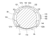
- the first belt member 121 and the second belt member 122 are recessed in the width direction of the support member 120 (the long axis direction D1 of the foot in the mounted state) at positions facing each other in the mounted state.
- a pair of recesses 123 are provided.
- the measurement device 100 can be prevented from shifting downward in the long axis direction D1 of the foot by bringing the pair of recesses 123 into contact with the ankle of the ankle B1 (corresponding to the convex portion of the limb).
- the first belt member 121 and the second belt member 122 are preferably made of a material having a higher elastic modulus than that of the sensor 110.
- the support member 120 is prevented from expanding and contracting, and the edema of the ankle B1 is suppressed.
- the amount and the amount of expansion / contraction of the sensor 110 in the expansion / contraction direction X1 can be made to correspond.
- the first belt member 121 and the second belt member 122 are preferably provided with flexibility so as to bend in accordance with a change in the amount of edema of the ankle B1.
- the material having a higher elastic modulus than the sensor 110 and having flexibility is not particularly limited, but examples thereof include polyvinyl chloride, polyethylene, polypropylene, polybutadiene, and an ethylene-vinyl acetate copolymer (EVA).
- EVA ethylene-vinyl acetate copolymer
- Polyolefins such as the above, polyesters such as polyethylene terephthalate (PET), polybutylene terephthalate (PBT), polyvinylidene chloride, or any combination thereof (blend resin, polymer alloy, laminate, etc.).
- a plurality of projections 124 projecting toward the ankle B1 are provided on the surfaces of the first belt member 121 and the second belt member 122 facing the ankle B1. As shown in FIGS. 4A and 4B, the protrusion 124 suppresses the support member 120 from coming into contact with the ankle B1 in the mounted state. Therefore, compared with the case where the protrusion 124 is not provided on the support member 120 and the support member 120 is in contact with the ankle B1, the measurement apparatus 100 according to the present embodiment generates an indentation even if an indentation occurs. The area can be reduced.
- each projection 124 on the side in contact with the ankle B1 has a rounded shape in order to prevent the wearer (patient) from feeling pain.
- the plurality of protrusions 124 are arranged so as to be separated from each other and aligned in the longitudinal direction X2 of the first belt member 121 and the second belt member 122.
- 4A shows a form in which the measurement apparatus 100 includes four protrusions 124, the number of protrusions 124 included in the measurement apparatus 100 is not particularly limited. In addition, the measuring apparatus 100 may not include the protrusion 124.
- Each of the protrusions 124 is preferably made of a material having a hardness that does not deform when pressed against the ankle B1 when supporting the support member 120 with respect to the ankle B1.
- materials include, but are not limited to, acrylic resins, polyvinyl chloride (particularly rigid polyvinyl chloride), polyolefins such as polyethylene, polypropylene, and polybutadiene, polystyrene, and poly- (4-methylpentene-1).
- Polycarbonate ABS resin, polymethyl methacrylate (PMMA), polyacetal, polyacrylate, polyacrylonitrile, polyvinylidene fluoride, ionomer, acrylonitrile-butadiene-styrene copolymer, polyethylene terephthalate (PET), polybutylene terephthalate (PBT) And fluorinated resins such as polyester, butadiene-styrene copolymer, aromatic or aliphatic polyamide, and polytetrafluoroethylene.
- the configuration of the support member 120 is not limited to the above as long as the support member 120 is attached to both ends 110a and 110b of the sensor 110 in the expansion / contraction direction X1 and can surround the ankle B1 together with the sensor 110.
- the support member 120 may be configured by a single long belt member.
- the support member 120 may be composed of one or two long wire members.
- the adjustment member 130 is configured to be able to adjust the length (peripheral length) of a portion (hereinafter referred to as “enclosed portion”) that surrounds the ankle B1 of the support member 120 in the mounted state. .
- the adjustment member 130 includes a first adjustment portion 131 provided at the other end 121c of the first belt member 121 in the longitudinal direction X2 and the second belt member 122, as shown in FIG. 2nd adjustment part 132 provided in other end 122c of longitudinal direction X2.
- the first adjusting portion 131 and the second adjusting portion 132 can connect and separate the other end portion 121c of the first belt member 121 in the longitudinal direction X2 and the other end portion 122c of the second belt member 122 in the longitudinal direction X2. And a function as a connecting portion capable of adjusting the connecting position in the longitudinal direction X2.
- the connecting portion is not particularly limited.
- the other end portion 121c of the first belt member 121 in the longitudinal direction X2 and the other end portion 122c of the second belt member 122 in the longitudinal direction X2 are fitted together.
- the other end 121c in the longitudinal direction X2 of the first belt member 121 and the other end 122c in the longitudinal direction X2 of the second belt member 122 may be magnetically coupled to each other. You may comprise so that it may connect by adsorption force, such as.
- the first adjustment unit 131 and the second adjustment unit 132 also have a function as a length detection unit that can electrically detect the circumferential length of the surrounding portion of the support member 120.
- the first adjustment unit 131 and the second adjustment unit 132 electrically detect the contact position in the longitudinal direction X2 between the first adjustment unit 131 and the second adjustment unit 132, so that the circumferential length of the surrounding portion. Is configured to be electrically detectable.
- the contact position of the first adjustment unit 131 and the second adjustment unit 132 can be continuously detected in the longitudinal direction X2.
- a method for continuously detecting the contact position in the longitudinal direction X2 is not particularly limited.
- the first adjustment unit 131 is configured by a long resistive element extending in the longitudinal direction X2, and the second adjustment unit 132 is formed.
- the resistor element is configured by a terminal that can contact an arbitrary position in the longitudinal direction X2.
- One end portion and a terminal of the resistance element in the longitudinal direction X2 are electrically connected to the control unit 160.
- the first adjustment unit 131 may be configured with a terminal
- the second adjustment unit 132 may be configured with a resistance element
- the connecting position of the first adjusting unit 131 and the second adjusting unit 132 may be discretely adjustable and detectable in the longitudinal direction X2.
- a method of discretely adjusting and detecting the connection position in the longitudinal direction X2 by the first adjusting unit 131 and the second adjusting unit 132 is not particularly limited, but for example, the first adjusting unit 131 is moved in the longitudinal direction X2.
- a method in which the second adjusting unit 132 is configured by a terminal that can contact each electrical contact. Each electrical contact and terminal is electrically connected to the control unit 160. Depending on which electrical contact is energized, the connection position in the longitudinal direction X2 of the first adjustment unit 131 and the second adjustment unit 132 can be detected.
- the 1st adjustment part 131 may be comprised by a terminal, and the 2nd adjustment part 132 may be comprised by a some electrical contact.
- the distance between the adjacent electrical contacts is set to such an extent that the measuring device 100 can be fitted to the wearer's ankle without depending on the individual difference of the wearer.
- the position where the adjustment member 130 is provided is not limited to the above as long as the circumference of the surrounding portion of the support member 120 can be adjusted.
- the adjustment member 130 may be provided at an intermediate portion of the first belt member 121 and the second belt member 122 in the longitudinal direction X2.
- the restricting member 140 is configured to be attachable to and detachable from the support member 120.
- the restriction member 140 covers the sensor 110 in the expansion / contraction direction X1 and restricts the sensor 110 from expanding / contraction in the expansion / contraction direction X1 when attached to the support member 120. Therefore, the measuring apparatus 100 can adjust the circumferential length of the surrounding portion of the support member 120 with the adjustment member 130 in a state where the length of the sensor 110 in the expansion / contraction direction X1 is maintained at the reference length L0 by the restriction member 140. Therefore, as shown in FIG.
- the measuring apparatus 100 can measure the expansion / contraction amount ⁇ L in the expansion / contraction direction X1 from the reference length L0 of the sensor 110 in a state where the restriction member 140 is removed from the support member 120.
- the restriction member 140 and the adjustment member 130 are configured so that the length of the surrounding portion of the adjustment member 130 is maintained in the state in which the length of the sensor 110 in the expansion / contraction direction X1 is maintained at the reference length L0 before the measurement by the measurement device 100 is started. Used at the initial setting to adjust the thickness.
- the regulating member 140 is attached to the support member 120, and is provided on the body portion 141 that covers the sensor 110 in the expansion / contraction direction X ⁇ b> 1 and both ends of the body portion 141. And two protrusions 142 and 143 that can be inserted into the holes 121b and 122b.
- the main body 141 has an arc shape in this embodiment.
- the shape of the main body 141 is not particularly limited as long as the sensor 110 can be covered in the expansion / contraction direction X1 in a state where the main body 141 is attached to the support member 120.
- the regulating member 140 is preferably made of a material having a hardness higher than that of the sensor 110 in order to regulate the expansion and contraction of the sensor 110 while being attached to the support member 120.
- materials include, but are not limited to, acrylic resins, polyvinyl chloride (particularly rigid polyvinyl chloride), polyolefins such as polyethylene, polypropylene, and polybutadiene, polystyrene, and poly- (4-methylpentene-1).
- Polycarbonate ABS resin, polymethyl methacrylate (PMMA), polyacetal, polyacrylate, polyacrylonitrile, polyvinylidene fluoride, ionomer, acrylonitrile-butadiene-styrene copolymer, polyethylene terephthalate (PET), polybutylene terephthalate (PBT) And fluorinated resins such as polyester, butadiene-styrene copolymer, aromatic or aliphatic polyamide, and polytetrafluoroethylene.
- the configuration of the regulating member 140 is attachable to and detachable from the support member 120, and covers the sensor 110 in the expansion / contraction direction X1 while being attached to the support member 120, and the sensor 110 extends in the expansion / contraction direction X1.
- the regulating member 140 can be attached to and removed from the support member 120 by an adsorbing force such as a magnetic force, rather than being attached to the support member 120 by inserting the protrusions 142 and 143 into the holes 121b and 122b of the support member 120. May be configured.
- the communication unit 150 is an interface for transmitting measurement data to an external device (not shown).
- an external device is not specifically limited, For example, it is PC etc., such as a doctor.
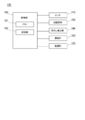
- the control unit 160 includes a known microcomputer including a CPU 161, a storage unit 162, and the like.
- the CPU 161 executes control of each unit, various arithmetic processes, and the like according to various programs stored in the storage unit 162.
- the storage unit 162 is configured by a ROM (Read Only Memory) that stores various programs and various data, a RAM (Random Access Memory) that temporarily stores programs and data as a work area, and the like.
- the control unit 160 is electrically connected to the sensor 110, the adjustment member 130, the removal detection unit 144, the communication unit 150, and the power supply unit 170, and controls these operations.
- the CPU 161 controls the capacitance detection operation of sensor 110.
- the CPU 161 converts the detected capacitance of the sensor 110 into an expansion / contraction amount ⁇ L of the sensor 110 in the expansion / contraction direction X1.
- the CPU 161 causes the storage unit 162 to store the calculated expansion / contraction amount ⁇ L of the sensor 110 in the expansion / contraction direction X1.
- the CPU 161 controls the detecting operation of the connection position in the longitudinal direction X2 of the first adjustment unit 131 and the second adjustment unit 132 of the adjustment member 130, and the detected longitudinal direction X2 of the first adjustment unit 131 and the second adjustment unit 132. From the connection position, the circumference of the ankle B1 (hereinafter referred to as “the initial circumference of the ankle B1”) is calculated. The CPU 161 stores the calculated initial circumference of the ankle B1 in the storage unit 162.
- the control unit 160 controls a transmission operation in which the communication unit 150 transmits measurement data to an external device.
- the power supply unit 170 is not particularly limited as long as power can be supplied to each unit of the measurement apparatus 100, but can be configured by a battery, a battery, or the like.
- the communication unit 150, the control unit 160, and the power supply unit 170 are opposite to the surface facing the ankle B 1 of the second belt member 122 (the inner surface in the mounted state), as shown in FIG. (Outer surface in the mounted state).
- the positions where the communication unit 150, the control unit 160, and the power supply unit 170 are provided are not particularly limited as long as the expansion and contraction of the sensor 110 is not hindered.
- the communication unit 150, the control unit 160, and the power supply unit 170 may be provided on the outer surface of the first belt member 121, or are incorporated in the first belt member 121 or the second belt member 122. It may be provided as follows.
- initial setting is performed before the measurement apparatus 100 starts measurement.
- the wearer first attaches the regulating member 140 to the support member 120 as shown in FIG. 4A.
- the length of the sensor 110 in the expansion / contraction direction X1 is maintained at the reference length L0.
- the wearer winds the sensor 110 and the support member 120 around the ankle B1, and the adjustment member 130 causes the other end 121c of the first belt member 121 in the longitudinal direction X2 and the longitudinal direction of the second belt member 122 to move.
- the other end 122c of X2 is connected.
- the measuring apparatus 100 is attached to the ankle B1.
- the wearer adjusts the connection position in the longitudinal direction X2 of the first adjustment unit 131 and the second adjustment unit 132 of the adjustment member 130 so that the measurement apparatus 100 fits the ankle B1.
- the wearer removes the regulating member 140 from the support member 120.
- the removal detection unit 144 detects that the restriction member 140 has been removed from the support member 120.
- the CPU 161 of the control unit 160 starts measuring the expansion / contraction amount ⁇ L of the sensor 110.
- the adjustment member 130 detects the connection position of the first adjustment unit 131 and the second adjustment unit 132 in the longitudinal direction X2.
- the CPU 161 calculates the initial circumference of the ankle B1 based on the detected connection position of the first adjustment unit 131 and the second adjustment unit 132 in the longitudinal direction X2.
- the CPU 161 stores the calculated initial circumference of the ankle B1 in the storage unit 162.
- the CPU 161 is configured to cause the sensor 110 to detect the capacitance at predetermined time intervals (for example, every minute to every hour).
- the CPU 161 converts the detected capacitance of the sensor 110 into the amount of expansion / contraction of the sensor 110 in the expansion / contraction direction X1.
- the CPU 161 stores the calculated data of the expansion / contraction amount ⁇ L in the expansion / contraction direction X1 of the sensor 110 in the storage unit 162.
- the control unit 160 transmits the initial circumference of the ankle B1 and the measured expansion / contraction amount ⁇ L of the sensor 110 to the external device via the communication unit 150 at a predetermined timing.
- the timing at which the control unit 160 transmits the expansion / contraction amount ⁇ L of the sensor 110 to the external device is not particularly limited, for example, the control unit 160 is configured to perform a predetermined time interval (for example, a timing when the used capacity of the storage unit 162 exceeds a threshold , Every other day).
- the measuring device 100 is a measuring device capable of measuring the amount of edema of the ankle B1.
- the measuring device 100 has a sheet shape, and can be expanded and contracted in one direction (stretching direction X1) intersecting the thickness direction Y1, and can detect a change in electrical characteristics (capacitance) accompanying the stretching.
- a support member 120 that is attached to both end portions 110a and 110b of the sensor 110 in the expansion / contraction direction X1 and surrounds the ankle B1 together with the sensor 110 when the sensor 110 is attached to the ankle B1.
- the amount of edema of the ankle B1 can be measured while suppressing the formation of an indentation in the ankle B1 by the sensor 110 that can be freely expanded and contracted and can detect a change in electrical characteristics accompanying the expansion and contraction. Therefore, it is possible to provide the measuring apparatus 100 that can measure the edema amount of the ankle B1 more accurately.
- the senor 110 includes a base material 111 containing an elastomer material, and conductive layers 112a and 112b which are laminated in the thickness direction Y1 of the base material 111 and are integrally stretchable with the base material 111. Therefore, the base material 111 and the conductive layers 112a and 112b expand and contract according to the amount of edema, and the electrical characteristics of the sensor 110 can be changed along with the expansion and contraction.
- the support member 120 and the sensor 110 are annularly arranged around the ankle B1 in the mounted state. Therefore, the measuring apparatus 100 can measure the amount of edema of the ankle B1 by measuring a change in the circumference of the ankle B1.
- the measuring device 100 is provided on the support member 120, and can be attached to the support member 120 with the adjustment member 130 capable of adjusting the length of the portion of the support member 120 surrounding the ankle B1 in the mounted state. It further includes a regulating member 140 that is detachable and that regulates the expansion and contraction of the sensor 110 while being attached to the support member 120. Therefore, the length of the portion surrounding the ankle B1 in the support member 120 is adjusted by the adjustment member 130 in a state where the restriction member 140 is attached to the support member 120 and the length of the sensor 110 in the expansion / contraction direction X1 is maintained at the reference length L0. can do. Therefore, the measuring apparatus 100 can measure the expansion / contraction amount ⁇ L from the reference length L0 of the sensor 110.
- the adjustment member 130 has a function as a length detection unit that can electrically detect the length of the portion surrounding the ankle B1 when the support member 120 is mounted. Therefore, the measuring apparatus 100 can measure the circumference of the ankle B1.
- a plurality of protrusions 124 that protrude toward the ankle B1 are provided on the surface of the support member 120 that faces the ankle B1 in the mounted state. Therefore, it can suppress that the supporting member 120 contacts ankle B1, and can reduce the area which an indentation produces.
- the support member 120 is made of a material having a higher elastic modulus than the sensor 110. Therefore, it is possible to suppress the support member 120 from expanding and contracting according to the amount of edema of the ankle B1, and to associate the amount of edema of the ankle B1 with the amount of expansion and contraction of the sensor 110.
- the support member 120 is provided with a recess 123 that is formed so as to be recessed in the long axis direction D1 of the foot in the mounted state, and abuts against the ankle of the ankle B1. Therefore, in the wearing state, it is possible to prevent the measuring device 100 from being shifted downward in the long axis direction D1 of the foot by bringing the concave portion 123 into contact with the ankle of the ankle B1.
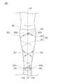
- FIG. 6 is a diagram for explaining the overall configuration of the measuring apparatus 200 according to the second embodiment.
- 7 to 8B are diagrams for explaining each part of the measuring apparatus 200 according to the second embodiment.
- the measuring apparatus 200 according to the second embodiment is the first embodiment in that the support member 220 is spirally arranged around the lower leg B ⁇ b> 2 (corresponding to “limb”) in the mounted state. This is different from the measuring apparatus 100 according to FIG. Hereinafter, the measuring apparatus 200 according to the second embodiment will be described.
- symbol is attached
- the measuring apparatus 200 holds the sensor 110, a support member 220 that is attached to the sensor 110 and surrounds the lower leg B ⁇ b> 2 together with the sensor 110, and the support member 220.
- a holding member 280 and an adjustment member 230 attached to the support member 220 are provided.
- the measuring device 200 includes a regulating member 140 that can be attached to and detached from the support member 220, a communication unit 150 that can communicate with an external device, and a control unit 160 that controls the operation of each unit.
- a power supply unit 170 capable of supplying power to each unit.
- the support member 220 includes a long first wire member 221 and a second wire member 222, and a first wire member 221 and a second wire member 222 in this embodiment.
- a first connection part 223 and a second connection part 224 connected to the sensor 110 are provided.
- One end 221a in the longitudinal direction of the first wire member 221 is connected to one end 110a in the expansion / contraction direction X1 of the sensor 110 via the first connection portion 223.
- One end portion 222 a in the longitudinal direction of the second wire member 222 is connected to the other end portion 110 b in the expansion / contraction direction X ⁇ b> 1 of the sensor 110 through the second connection portion 224.
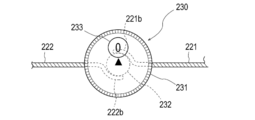
- the other end 221b in the longitudinal direction of the first wire member 221 and the other end 222b in the longitudinal direction of the second wire member 222 are connected to the adjustment member 230 as shown in FIG. 8A.
- the first wire member 221 and the second wire member 222 are spirally arranged around the lower leg B2 as shown in FIG. 6 in the mounted state.
- the first wire member 221 and the second wire pull the sensor 110 in the expansion / contraction direction X1. Therefore, the sensor 110 can measure the amount of edema within a certain range (a range surrounded by the support member 220) in the long axis direction D2 of the lower leg B2. Therefore, compared with the measuring apparatus 100 according to the first embodiment, the measuring apparatus 200 according to the second embodiment can measure a wider range of edema amounts.
- the first wire member 221 and the second wire member 222 are preferably made of a material having a higher elastic modulus than the sensor 110. By configuring the first wire member 221 and the second wire member 222 with such a material, the first wire member 221 and the second wire member 222 expand and contract when edema occurs in the lower leg B2. Can be made to correspond to the amount of edema of the ankle B1 and the amount of expansion / contraction of the sensor 110.
- first wire member 221 and the second wire member 222 have flexibility so as to bend in accordance with a change in the amount of edema of the lower leg B2.
- a material having a higher elastic modulus than that of the sensor 110 and having flexibility is not particularly limited.
- the same material as the constituent material of the support member 120 according to the first embodiment can be used.
- the first connection part 223 and the second connection part 224 have a plate shape as shown in FIG. Holes 223a and 224a into which the protrusions 142 and 143 of the regulating member 140 can be inserted are provided on the surface opposite to the surface facing the crus B2 in the mounted state in the first connection portion 223 and the second connection portion 224. ing.
- the second connection unit 224 includes a communication unit 150, a control unit 160, a power supply unit 170, and the like, as shown in FIG.
- the communication unit 150, the control unit 160, the power supply unit 170, and the like may be built in the first connection unit 223 or may be built in another member of the measuring apparatus 200.
- the holding member 280 is provided in the cylindrical main body 281 and the main body 281, and a plurality of insertion portions 282 through which the first wire member 221 and the second wire member 222 can be inserted. And.
- the main body 281 is constituted by stockings formed by braiding yarn. Therefore, the main body 281 can be deformed so as to fit the lower leg B2 in the mounted state.
- yarn which comprises the main-body part 281 is not specifically limited, For example, it can comprise with materials, such as a nylon thread
- the main body 281 is arranged so as to cover an area (particularly calves) from the lower leg to the upper part of the ankle in the wearing state. Therefore, it can suppress that the main-body part 281 fits to a calf, and position shift to the major axis direction D2 of crus B2.
- the shape of the main body 281 is not limited to the above.
- the main body 281 may be arranged so as to cover a part of the calf in the mounted state.
- the main body 281 may have a shape that surrounds not only the lower leg B2 but also the toes (toes). In either case, the wearer can easily wear the measuring apparatus 200 by passing the lower leg B2 through the main body 281.
- Each insertion part 282 is provided with the annular shape provided with the hole in this embodiment.
- the first wire member 221 and the second wire member 222 are held by the main body portion 281 by inserting the hole portion of the insertion portion 282.
- the plurality of insertion portions 282 are arranged so as to be spirally arranged in the main body portion 281 so that the first wire member 221 and the second wire member 222 are spirally arranged around the lower leg B2 in the mounted state. Yes.
- the configuration of the insertion portion 282 is not particularly limited as long as the first wire member 221 and the second wire member 222 can be inserted.
- the insertion part 282 may be configured by a hole provided in the main body part 281.
- the adjustment member 230 is the length of the portion surrounding the lower leg B2 of the first wire member 221 and the second wire member 222 in the mounted state (the first wire member 221 and the second wire
- the length of the spiral is adjustable. Therefore, in a state where the sensor 110 is maintained at the reference length L0 by the regulating member 140, the helical lengths of the first wire member 221 and the second wire member are adjusted, and the measuring device 200 can be fitted to the lower leg B2. it can. Therefore, the measuring apparatus 200 can measure the expansion / contraction amount ⁇ L from the reference length L0 of the sensor 110.
- the adjustment member 230 rotates in conjunction with the rotation of the dial 231, which can be rotated by the wearer, and the first wire member 221.
- a winding unit 232 that can wind up the second wire member 222
- a display unit 233 that displays the winding amount of the first wire member 221 and the second wire member 222, the first wire member 221 and the first wire member 221
- a notification unit 234 that notifies that the tension of the second wire member 222 has reached the threshold value.
- the dial 231 has a cylindrical shape in this embodiment.
- the shape of the dial 231 is not particularly limited as long as the wearer can rotate with a finger.
- the winding unit 232 has a substantially cylindrical shape.
- the winding unit 232 is disposed substantially at the center in the dial 231 and is connected to the dial 231 and can be rotated in conjunction with the rotation of the dial 231.
- the other end portion 221b of the first wire member 221 and the other end portion 222b of the second wire member 222 are connected to the winding portion 232 as shown in FIG. 8A. Therefore, as shown in FIG. 8B, the length of the portion surrounding the lower leg B2 of the first wire member 221 and the second wire member 222 (the first wire member 221 and the first wire member 221) The length along the spiral direction of the second wire member 222 changes.
- the display unit 233 is not particularly limited as long as the winding amount of the first wire member 221 and the second wire member 222 can be displayed.
- the display unit 233 may be configured by a display capable of displaying the rotation amount of the winding unit 232 detected by a rotation angle sensor or the like.
- the display unit 233 may be configured by a scale indicating the amount of rotation of the winding unit 232. Since the adjustment member 230 includes such a display portion 233, the wearer temporarily loosens the first wire member 221 and the second wire member 222 and removes the measurement device 100 from the lower leg B2. In doing so, the lengths of the spirals of the first wire member 221 and the second wire member 222 can be adjusted again so as to be the original length.
- the notification unit 234 is configured by a protrusion that protrudes from the dial 231 when the tension of the first wire member 221 and the second wire member 222 reaches a threshold value.
- the configuration of the notification unit 234 is not particularly limited as long as it is possible to notify that the tension of the first wire member 221 and the second wire member 222 has reached the threshold value.
- the notification unit 234 may be configured by a display that displays that the tension of the first wire member 221 and the second wire member 222 has reached a threshold value.
- the display unit 233 may be configured by a speaker that sounds a buzzer when the tension of the first wire member 221 and the second wire member 222 reaches a threshold value. Therefore, the wearer can easily fit the measuring device 200 to the lower leg B2 by setting the tension of the first wire member 221 and the second wire member 222 to a predetermined magnitude.
- the support member 220 is arranged in a spiral shape around the lower leg B2 in the mounted state. Therefore, the measuring apparatus 200 can measure the edema amount in a certain range in the long axis direction D2 of the lower leg B2.
- the measuring device according to the present invention can be applied not only to a measuring device attached to an ankle or a lower leg, but also to a measuring device attached to a wrist or an arm.
- the stem-like projection of the wrist corresponds to the convex portion of the limb.
- 100 measuring device 110 sensors, 111 substrate, 112a, 112b conductive layer, 120, 220 support member, 123 protrusions, 124 recess, 130, 230 Adjustment member (length detection unit), 140 regulating member, X1 sensor expansion and contraction direction, Y1 sensor thickness direction, X2 longitudinal direction of the support member, D1 Long axis direction of the leg.
Landscapes
- Health & Medical Sciences (AREA)
- Life Sciences & Earth Sciences (AREA)
- Biomedical Technology (AREA)
- Heart & Thoracic Surgery (AREA)
- Veterinary Medicine (AREA)
- Biophysics (AREA)
- Pathology (AREA)
- Engineering & Computer Science (AREA)
- Public Health (AREA)
- Physics & Mathematics (AREA)
- Medical Informatics (AREA)
- Molecular Biology (AREA)
- Surgery (AREA)
- Animal Behavior & Ethology (AREA)
- General Health & Medical Sciences (AREA)
- Dentistry (AREA)
- Oral & Maxillofacial Surgery (AREA)
- Measurement Of The Respiration, Hearing Ability, Form, And Blood Characteristics Of Living Organisms (AREA)
Abstract
【課題】肢体の浮腫量をより正確に測定可能な測定装置を提供する。 【解決手段】本発明に係る測定装置100は、足首B1の浮腫量を測定可能な測定装置である。測定装置は、シート形状を備えるとともに、厚み方向Yと交差する一の方向X1に伸縮自在、かつ、伸縮に伴う電気的特性の変化を検出可能なセンサ110と、センサの伸縮方向の両端部110a、110bに取り付けられ、足首に装着された装着状態においてセンサとともに足首を包囲する支持部材120と、を有する。
Description
本発明は、肢体の浮腫量を測定可能な測定装置に関する。
肢体の浮腫は、心不全や肝不全等の疾患に伴って現れる症状の一つとして知られており、肢体の浮腫量を把握することは、これらの疾患の診断等を行う上で重要なことである。
例えば、下記特許文献1には、長尺状のバンドを肢体に巻き付け、バンドの端部同士を結合させた結合位置に基づいて肢体の周長を検出することによって、肢体の浮腫量を測定可能な装置が開示されている。
心不全や肝不全等の疾患に伴って生じる肢体の浮腫は、肢体が押圧された場合に肢体の押圧箇所において貯留した体液が押圧箇所から逃げ、押圧箇所に圧痕が生じる圧痕性浮腫として知られている。そのため、肢体に生じた浮腫が圧痕性浮腫である場合、上記特許文献1のような装置では、バンドが肢体に喰い込んで圧痕が生じ、正確な浮腫量が測定できない可能性がある。
本発明は、上記事情に鑑みてなされたものであり、肢体の浮腫量をより正確に測定可能な測定装置を提供することを目的とする。
上記目的を達成する本発明に係る測定装置は、肢体の浮腫量を測定可能な測定装置であって、シート形状を備えるとともに、厚み方向と交差する一の方向に伸縮自在、かつ、伸縮に伴う電気的特性の変化を検出可能なセンサと、前記センサの伸縮方向の両端部に取り付けられ、前記肢体に装着された装着状態で前記センサとともに前記肢体を包囲する支持部材と、を有する。
本発明に係る測定装置によれば、伸縮自在かつ伸縮に伴う電気的特性の変化を検出可能なセンサによって、肢体に圧痕が生じるのを抑制しつつ、肢体の浮腫量を測定できる。そのため、本発明によれば、肢体の浮腫量をより正確に測定可能な測定装置を提供できる。
以下、添付した図面を参照して、本発明の実施形態を説明する。なお、図面の説明において、同一の要素には同一の符号を付し、重複する説明を省略する。また、図面の寸法比率は、説明の都合上誇張されており、実際の比率とは異なる場合がある。
<第1実施形態>
図1は、第1実施形態に係る測定装置100の全体構成の説明に供する図である。図2~図5は、第1実施形態に係る測定装置100の各部の説明に供する図である。
図1は、第1実施形態に係る測定装置100の全体構成の説明に供する図である。図2~図5は、第1実施形態に係る測定装置100の各部の説明に供する図である。
第1実施形態に係る測定装置100は、図1に示すように、心不全や肝不全等の患者の足首B1(「肢体」に相当)に装着されるとともに、足首B1の周長を測定することによって、足首B1の浮腫量を測定可能な装置として構成している。なお、本明細書において、「足首B1の周長」とは、足の長軸方向D1周りの足首B1の長さのことを意味する。また、測定装置100の装着者は、心不全や肝不全等の患者に特に限定されない。
第1実施形態に係る測定装置100は、概説すると、導電性を備えるシート状のセンサ110と、センサ110に取り付けられ、足首B1に装着された装着状態でセンサ110とともに肢体を包囲する支持部材120と、支持部材120の長さを調整可能な調整部材130と、センサ110の長さを規制可能な規制部材140と、外部装置と通信可能な通信部150と、各部の動作を制御する制御部160と、各部に電力を供給可能な電源部170と、を有している。以下、測定装置100の各部について詳述する。
(センサ)
センサ110は、本実施形態では、図1に示すように、導電性およびシート形状を備えている。センサ110は、本実施形態では、センサ110の厚み方向Y1と交差する一の方向(以下、「伸縮方向X1」と称する。)に伸縮自在であり、かつ、伸縮方向X1の伸縮に伴う電気特性の変化を検出可能に構成している。なお、本明細書において、「伸縮自在」とは、肢体の浮腫量(肢体の容積)が変化するのに追従して肢体に装着したセンサ110が伸縮方向X1に弾性変形自在であることを意味する。
センサ110は、本実施形態では、図1に示すように、導電性およびシート形状を備えている。センサ110は、本実施形態では、センサ110の厚み方向Y1と交差する一の方向(以下、「伸縮方向X1」と称する。)に伸縮自在であり、かつ、伸縮方向X1の伸縮に伴う電気特性の変化を検出可能に構成している。なお、本明細書において、「伸縮自在」とは、肢体の浮腫量(肢体の容積)が変化するのに追従して肢体に装着したセンサ110が伸縮方向X1に弾性変形自在であることを意味する。
センサ110は、本実施形態では、図1に示すように、長尺状のシート形状を備えている。センサ110の伸縮方向X1は、本実施形態では、センサ110の長手方向(足首Bに測定装置100が装着された装着状態での周方向)に相当する。ただし、センサ110の形状は、シート形状である限り特に限定されない。例えば、センサ110は、略正方形状を備えていてもよい(すなわち、センサ110は長尺状でなくてもよい)。このように、センサ110は、シート形状を備えているため、厚み方向Y1と交差する一の方向(伸縮方向X1)に容易に伸縮できる。そのため、センサ110によって、足首B1に圧痕が生じるのを抑制しつつ、足首B1の浮腫量を測定できる。
センサ110は、本実施形態では、図2に示すように、長尺状のシート形状を備える基材111と、基材111を挟み込むように厚み方向Y1に積層される一対の導電層112a、112bと、一対の導電層112a、112bを挟み込むように厚み方向Y1に積層される一対の保護層113a、113bと、を備えるコンデンサによって構成している。
基材111は、伸縮方向X1に伸縮自在に構成している。基材111は、本実施形態では、コンデンサの誘電体として機能する。基材111が伸縮方向X1に伸縮すると、基材111の伸縮方向X1の長さおよび厚み方向Y1の長さ(厚み)が変化する。センサ110の静電容量(「電気的特性」に相当)は、センサ110の伸縮方向X1の長さおよび厚み(一対の導電層112a、112bの距離)に依存する。そのため、センサ110の電気的特性である静電容量を検出することによって、センサ110の伸縮方向X1の伸縮量、すなわち、足首B11の浮腫量を測定できる。
基材111は、伸縮性に優れることから、エラストマー材料を主に含む材料によって構成することが好ましい。基材111に使用するエラストマー材料としては、例えば、天然ゴム、イソプレンゴム、ニトリルゴム(NBR)、エチレンプロピレンゴム(EPDM)、スチレン・ブタジエンゴム(SBR)、ブタジエンゴム(BR)、クロロプレンゴム(CR)、シリコーンゴム、フッ素ゴム、アクリルゴム、水素添加ニトリルゴム、ウレタンゴム、これらの中から2種以上を組み合わせたもの等が挙げられる。特に、基材111に使用するエラストマー材料としては、永久歪みが小さく、かつ、後述する各導電層112a、112bに含まれるカーボンナノチューブとの密着性に優れることから、ウレタンゴムを用いることが好ましい。また、基材111は、伸縮性を阻害しない範囲でエラストマー材料以外に、誘電フィラー(チタン酸バリウム等)、可塑剤、鎖延長剤、架橋剤、触媒、加硫促進剤、酸化防止剤、老化防止剤、着色剤等の添加剤を含有してもよい。
各導電層112a、112bは、基材111と一体化しており、基材111と一体的に伸縮方向X1に伸縮可能に構成している。
各導電層112a、112bは、センサ110からの信号をAD変換可能なトランスミッタ(図示省略)等を介して制御部160に電気的に接続されている。
各導電層112a、112bの構成材料は、導電性を備え、かつ、基材111と一体的に伸縮可能である限り特に限定されないが、例えば、カーボンナノチューブを主に含む材料によって構成できる。各導電層112a、112bに使用するカーボンナノチューブは、特に限定されないが、例えば、単層カーボンナノチューブ、多層カーボンナノチューブ、および単層カーボンナノチューブと多層カーボナノチューブを混合したもの等を用いることができる。各導電層112a、112bは、カーボンナノチューブ以外に、バインダ、架橋剤、加硫促進剤、加硫助剤、老化防止剤、可塑剤、軟化剤、着色剤等を含んでいてもよい。各導電層112a、112bに使用されるバインダとしては、特に限定されないが、例えば、ブチルゴム、エチレンプロピレンゴム、ポリエチレン、クロロスルホン化ポリエチレン、天然ゴム、イソプレンゴム、ブタジエンゴム、スチレン・ブタジエンゴム、ポリスチレン、クロロプレンゴム、ニトリルゴム、ポリメタクリル酸メチル、ポリ酢酸ビニル、ポリ塩化ビニル、アクリルゴム、スチレン-エチレン-ブチレン-スチレンブロック共重合体、これらの中から2種以上を組み合わせたもの等が挙げられる。
保護層113a、113bは、各導電層112a、112bと一体化しており、基材111および一対の導電層112a、112bと一体的に伸縮方向X1に伸縮可能に構成している。
保護層113a、113bの構成材料としては、例えば、基材111の構成材料と同様の材料を用いることができる。
なお、センサ110は、導電性およびシート形状を備えるとともに、厚み方向Y1と交差する一の方向に伸縮自在、かつ、伸縮に伴う電気的特性の変化を検出可能である限り特に限定されない。例えば、センサ110は、基材111と、基材111の一方の面に設けられた一の導電層112aと、によって構成してもよい。この場合、センサ110の伸縮に伴い導電層112a内のカーボンナノチューブ同士の距離が変化し、それによってセンサ110の電気抵抗が変化する。そのため、センサ110の電気的特性である電気抵抗を検出することによって、センサ110の伸縮方向X1の伸縮量の変化、すなわち、足首B11の浮腫量の変化を測定できる。
(支持部材)
支持部材120は、本実施形態では、図1に示すように、センサ110の伸縮方向X1の両端部110a、110bに取り付けられ、測定装置100が足首B1に装着された装着状態でセンサ110とともに足首B1を包囲する。そのため、支持部材120は、装着状態で、センサ110を足首B1に固定するとともに、足首B1に浮腫が生じた際に、センサ110の伸縮方向X1の両端部110a、110bを引っ張り、センサ110を引き伸ばす。
支持部材120は、本実施形態では、図1に示すように、センサ110の伸縮方向X1の両端部110a、110bに取り付けられ、測定装置100が足首B1に装着された装着状態でセンサ110とともに足首B1を包囲する。そのため、支持部材120は、装着状態で、センサ110を足首B1に固定するとともに、足首B1に浮腫が生じた際に、センサ110の伸縮方向X1の両端部110a、110bを引っ張り、センサ110を引き伸ばす。
支持部材120は、本実施形態では、図1に示すように、長尺状の第1のベルト部材121および第2のベルト部材122によって構成している。
第1のベルト部材121の長手方向X2(装着状態での周方向)の一の端部121aは、センサ110の伸縮方向X1の一の端部110aに接続されている。第2のベルト部材122の長手方向X2の一の端部122aは、センサ110の伸縮方向X1の他の端部110bに接続されている。なお、本明細書において、「伸縮方向X1または長手方向X2の端部」は、各部材の伸縮方向X1または長手方向X2の最先端だけでなく、最先端から伸縮方向X1または長手方向X2に一定の範囲も含む。
第1のベルト部材121の長手方向X2の一の端部121aおよび第2のベルト部材122の長手方向X2の一の端部122aには、後述する規制部材140の突起142、143を挿入可能な孔部121b、122bが設けられている。
孔部122bの奥には、図4Aおよび図4Bに示すように、突起143が孔部122bに挿入されていないこと(すなわち、後述する規制部材140が取り外されたこと)を電気的に検出する取外し検出部144が設けられている。取外し検出部144は、制御部160に電気的に接続されている。なお、取外し検出部144は、孔部121bの奥に設けられていてもよい。
図1に示すように、第1のベルト部材121の長手方向X2の他の端部121c、および、第2のベルト部材122の長手方向X2の他の端部122cには、調整部材130が設けられている。測定装置100は、図4Aおよび図4Bに示すように、足首B1にセンサ110および支持部材120を巻き付け、かつ、第1のベルト部材121の長手方向の他の端部121cと第2のベルト部材122の長手方向の他の端部122cを調整部材130によって連結することによって足首B1に装着される。第1のベルト部材121および第2のベルト部材122は、装着状態で、センサ110とともに足首B1周りに環状に配置される。そのため、測定装置100は、足首B1の周長、すなわち、足首B1の浮腫量を測定できる。
第1のベルト部材121および第2のベルト部材122には、図1に示すように、装着状態で対向する位置に、支持部材120の幅方向(装着状態で足の長軸方向D1)に凹む一対の凹部123が設けられている。装着状態において、足首B1のくるぶし(肢体の凸部に相当)に一対の凹部123を当接させることによって測定装置100が足の長軸方向D1の下方にずれるのを抑制できる。
第1のベルト部材121および第2のベルト部材122は、センサ110よりも弾性率の高い材料によって構成することが好ましい。第1のベルト部材121および第2のベルト部材122を、このような材料によって構成することにより、足首B1に浮腫が生じた際に、支持部材120が伸縮するのを抑制し、足首B1の浮腫量とセンサ110の伸縮方向X1の伸縮量を対応させることができる。
また、第1のベルト部材121および第2のベルト部材122は、図4Aおよび図4Bに示すように、足首B1の浮腫量の変化に応じて撓むように可撓性を備えることが好ましい。センサ110よりも弾性率の高く、かつ、可撓性を備えるような材料としては、特に限定されないが、例えば、ポリ塩化ビニル、ポリエチレン、ポリプロピレン、ポリブタジエン、エチレン-酢酸ビニル共重合体(EVA)のようなポリオレフィン、ポリエチレンテレフタレート(PET)、ポリブチレンテレフタレート(PBT)のようなポリエステル、ポリ塩化ビニリデン、あるいはこれらを任意に組み合わせたもの(ブレンド樹脂、ポリマーアロイ、積層体等)が挙げられる。
第1のベルト部材121および第2のベルト部材122の足首B1に臨む面には、足首B1に向かって突出する複数の突起124が設けられている。突起124は、図4Aおよび図4Bに示すように、装着状態では、支持部材120が足首B1に接触するのを抑制する。そのため、突起124が支持部材120に設けられておらず、支持部材120が足首B1に接触する場合と比較すると、本実施形態に係る測定装置100は、仮に圧痕が生じたとしても、圧痕が生じる面積を低減できる。
各突起124において足首B1と接触する側の端部は、装着者(患者)が痛みを感じるのを抑制するために、丸みを帯びた形状であることが好ましい。複数の突起124は、互いに離間するとともに、第1のベルト部材121および第2のベルト部材122の長手方向X2に並ぶように配置されている。なお、図4Aには、測定装置100が4つの突起124を備える形態を示しているが、測定装置100が備える突起124の数は特に限定されない。また、測定装置100は、突起124を備えなくてもよい。
各突起124は、足首B1に対して支持部材120を支持する上で、足首B1に押し当てられた際に変形しない程度の硬度を備える材料によって構成することが好ましい。そのような材料としては、特に限定されないが、例えば、アクリル樹脂、ポリ塩化ビニル(特に硬質ポリ塩化ビニル)、ポリエチレン、ポリプロピレン、ポリブタジエンのようなポリオレフィン、ポリスチレン、ポリ-(4-メチルペンテン-1)、ポリカーボネート、ABS樹脂、ポリメチルメタクリレート(PMMA)、ポリアセタール、ポリアクリレート、ポリアクリロニトリル、ポリフッ化ビニリデン、アイオノマー、アクリロニトリル-ブタジエン-スチレン共重合体、ポリエチレンテレフタレート(PET)、ポリブチレンテレフタレート(PBT)のようなポリエステル、ブタジエン-スチレン共重合体、芳香族または脂肪族ポリアミド、ポリテトラフルオロエチレン等のフッ素系樹脂等が挙げられる。
なお、支持部材120の構成は、センサ110の伸縮方向X1の両端部110a、110bに取り付けられるとともに、センサ110とともに足首B1を包囲可能である限り上記に限定されない。例えば、支持部材120は、1本の長尺状のベルト部材によって構成されていてもよい。また、支持部材120は、1本または2本の長尺状のワイヤ部材によって構成されていてもよい。
(調整部材)
調整部材130は、図4Aに示すように、装着状態で支持部材120の足首B1を包囲する部分(以下、「包囲部分」と称する)の長さ(周長)を調整可能に構成している。
調整部材130は、図4Aに示すように、装着状態で支持部材120の足首B1を包囲する部分(以下、「包囲部分」と称する)の長さ(周長)を調整可能に構成している。
調整部材130は、本実施形態では、図3に示すように、第1のベルト部材121の長手方向X2の他の端部121cに設けられる第1調整部131と、第2のベルト部材122の長手方向X2の他の端部122cに設けられる第2調整部132と、を備えている。
第1調整部131と第2調整部132は、第1のベルト部材121の長手方向X2の他の端部121cと第2のベルト部材122の長手方向X2の他の端部122cを連結分離可能に構成するとともに、長手方向X2の連結位置を調整可能な連結部としての機能を備えている。連結部は、特に限定されないが、例えば、第1のベルト部材121の長手方向X2の他の端部121cと第2のベルト部材122の長手方向X2の他の端部122cを嵌合等のように機械的に連結するように構成してもよいし、第1のベルト部材121の長手方向X2の他の端部121cと第2のベルト部材122の長手方向X2の他の端部122cを磁力等の吸着力によって連結するように構成してもよい。
第1調整部131および第2調整部132は、支持部材120の包囲部分の周長を電気的に検出可能な長さ検出部としての機能も備えている。第1調整部131および第2調整部132は、本実施形態では、第1調整部131と第2調整部132の長手方向X2の接触位置を電気的に検出することによって、包囲部分の周長を電気的に検出可能に構成している。
第1調整部131および第2調整部132の接触位置は、長手方向X2に連続的に検出可能であることが好ましい。接触位置を長手方向X2に連続的に検出する方法としては、特に限定されないが、例えば、第1調整部131を長手方向X2に延びる長尺状の抵抗素子によって構成し、第2調整部132を抵抗素子の長手方向X2の任意の位置に接触可能な端子によって構成する方法が挙げられる。抵抗素子の長手方向X2の一方の端部および端子は、制御部160に電気的に接続されている。抵抗素子と端子の長手方向X2の接触位置に応じて電気抵抗が変化することから、第1調整部131および第2調整部132の長手方向X2の接触位置を電気的に検出することができる。なお、第1調整部131を端子によって構成し、第2調整部132を抵抗素子によって構成してもよい。
第1調整部131および第2調整部132の連結位置は、長手方向X2に離散的に調整可能、かつ、検出可能であってもよい。第1調整部131および第2調整部132によって、連結位置を長手方向X2に離散的に調整し、かつ、検出する方法としては、特に限定されないが、例えば、第1調整部131を長手方向X2に並んで配置された複数の電気接点によって構成し、第2調整部132を各電気接点に接触可能な端子によって構成する方法等が挙げられる。各電気接点および端子は、制御部160に電気的に接続されている。どの電気接点が通電したかに応じて、第1調整部131および第2調整部132の長手方向X2の連結位置を検出できる。なお、第1調整部131を端子によって構成し、第2調整部132を複数の電気接点によって構成してもよい。いずれの場合も、隣合う電気接点同士の距離は、装着者の個人差に依らずに測定装置100を装着者の足首にフィット可能な程度に設定することが好ましい。
なお、調整部材130を設ける位置は、支持部材120の包囲部分の周長を調整可能である限り、上記に限定されない。例えば、調整部材130は、第1のベルト部材121のおよび第2のベルト部材122の長手方向X2の中間部分に設けてもよい。
(規制部材)
規制部材140は、図4Aおよび図4Bに示すように、支持部材120に取り付け可能、かつ、取り外し可能に構成している。規制部材140は、図4Aに示すように、支持部材120に取り付けられた状態では、センサ110を伸縮方向X1に覆い、センサ110が伸縮方向X1に伸縮するのを規制する。そのため、測定装置100は、規制部材140によってセンサ110の伸縮方向X1の長さを基準長L0に保った状態で、支持部材120の包囲部分の周長を調整部材130によって調整できる。そのため、測定装置100は、図4Bに示すように、規制部材140を支持部材120から取り外した状態では、センサ110の基準長L0からの伸縮方向X1の伸縮量ΔLを測定することができる。このように、規制部材140および調整部材130は、測定装置100による測定を開始する前に、センサ110の伸縮方向X1の長さを基準長L0に保った状態で調整部材130の包囲部分の長さを調整する初期設定時に用いられる。
規制部材140は、図4Aおよび図4Bに示すように、支持部材120に取り付け可能、かつ、取り外し可能に構成している。規制部材140は、図4Aに示すように、支持部材120に取り付けられた状態では、センサ110を伸縮方向X1に覆い、センサ110が伸縮方向X1に伸縮するのを規制する。そのため、測定装置100は、規制部材140によってセンサ110の伸縮方向X1の長さを基準長L0に保った状態で、支持部材120の包囲部分の周長を調整部材130によって調整できる。そのため、測定装置100は、図4Bに示すように、規制部材140を支持部材120から取り外した状態では、センサ110の基準長L0からの伸縮方向X1の伸縮量ΔLを測定することができる。このように、規制部材140および調整部材130は、測定装置100による測定を開始する前に、センサ110の伸縮方向X1の長さを基準長L0に保った状態で調整部材130の包囲部分の長さを調整する初期設定時に用いられる。
規制部材140は、図1に示すように、支持部材120に取り付けられた状態で、センサ110を伸縮方向X1に覆う本体部141と、本体部141の両端部に設けられるとともに、支持部材120の孔部121b、122bに挿入可能な2つの突起142、143と、を備えている。
本体部141は、本実施形態では、円弧形状を備えている。ただし、本体部141の形状は、本体部141が支持部材120に取り付けられた状態でセンサ110を伸縮方向X1に覆うことができる限り特に限定されない。
規制部材140は、支持部材120に取り付けられた状態でセンサ110の伸縮を規制するために、センサ110よりも硬度の高い材料によって構成することが好ましい。そのような材料としては、特に限定されないが、例えば、アクリル樹脂、ポリ塩化ビニル(特に硬質ポリ塩化ビニル)、ポリエチレン、ポリプロピレン、ポリブタジエンのようなポリオレフィン、ポリスチレン、ポリ-(4-メチルペンテン-1)、ポリカーボネート、ABS樹脂、ポリメチルメタクリレート(PMMA)、ポリアセタール、ポリアクリレート、ポリアクリロニトリル、ポリフッ化ビニリデン、アイオノマー、アクリロニトリル-ブタジエン-スチレン共重合体、ポリエチレンテレフタレート(PET)、ポリブチレンテレフタレート(PBT)のようなポリエステル、ブタジエン-スチレン共重合体、芳香族または脂肪族ポリアミド、ポリテトラフルオロエチレン等のフッ素系樹脂等が挙げられる。
なお、規制部材140の構成は、支持部材120に取り付け可能、かつ、取り外し可能であるとともに、支持部材120に取り付けられた状態で、センサ110を伸縮方向X1に覆い、センサ110が伸縮方向X1に伸縮するのを規制可能である限り特に限定されない。例えば、規制部材140は、突起142、143を支持部材120の孔部121b、122bに挿入することによって支持部材120に取り付けるのではなく、磁力等の吸着力によって支持部材120に取り付け可能および取り外し可能に構成されてもよい。
(通信部)
通信部150は、外部装置(図示省略)等に測定データを送信するためのインターフェースである。外部装置は、特に限定されないが、例えば、医師等のPC等である。
通信部150は、外部装置(図示省略)等に測定データを送信するためのインターフェースである。外部装置は、特に限定されないが、例えば、医師等のPC等である。
(制御部)
制御部160は、図5に示すように、CPU161、および記憶部162等を含む公知のマイクロコンピュータにより構成している。CPU161は、記憶部162に記憶されている各種プログラムに従って、各部の制御や各種の演算処理などを実行する。記憶部162は、各種プログラムや各種データを記憶するROM(Read Only Memory)、作業領域として一時的にプログラムやデータを記憶するRAM(Randam Access Memory)等によって構成している。
制御部160は、図5に示すように、CPU161、および記憶部162等を含む公知のマイクロコンピュータにより構成している。CPU161は、記憶部162に記憶されている各種プログラムに従って、各部の制御や各種の演算処理などを実行する。記憶部162は、各種プログラムや各種データを記憶するROM(Read Only Memory)、作業領域として一時的にプログラムやデータを記憶するRAM(Randam Access Memory)等によって構成している。
制御部160は、センサ110、調整部材130、取外し検出部144、通信部150、および電源部170に電気的に接続されており、これらの動作を制御する。
CPU161は、センサ110の静電容量の検出動作を制御する。CPU161は、検出したセンサ110の静電容量をセンサ110の伸縮方向X1の伸縮量ΔLに換算する。CPU161は、算出したセンサ110の伸縮方向X1の伸縮量ΔLを記憶部162に記憶させる。
CPU161は、調整部材130の第1調整部131と第2調整部132の長手方向X2の連結位置の検出動作を制御するとともに、検出した第1調整部131と第2調整部132の長手方向X2の連結位置から、足首B1の周長(以下、「足首B1の初期の周長」と称する)を算出する。CPU161は、算出した足首B1の初期の周長を記憶部162に記憶させる。
制御部160は、通信部150が外部装置に測定データを送信する送信動作を制御する。
(電源部)
電源部170は、測定装置100の各部に電力を供給可能である限り特に限定されないが、電池やバッテリ等によって構成できる。
電源部170は、測定装置100の各部に電力を供給可能である限り特に限定されないが、電池やバッテリ等によって構成できる。
通信部150、制御部160、および電源部170は、本実施形態では、図1に示すように、第2のベルト部材122の足首B1に臨む面(装着状態での内面)と反対側の面(装着状態での外面)に設けられている。ただし、通信部150、制御部160、および電源部170を設ける位置は、センサ110の伸縮を阻害しない限り特に限定されない。例えば、通信部150、制御部160、および電源部170は、第1のベルト部材121の外面に設けられていてもよいし、第1のベルト部材121または第2のベルト部材122に内蔵されるように設けられていてもよい。
(使用方法)
次に、本実施形態に係る測定装置100の使用方法について説明する。
次に、本実施形態に係る測定装置100の使用方法について説明する。
まず、測定装置100が測定を開始する前に、初期設定を行う。
初期設定では、まず、装着者は、図4Aに示すように、規制部材140を支持部材120に取り付ける。これによって、センサ110の伸縮方向X1の長さが基準長L0に保たれる。
次に、装着者は、センサ110および支持部材120を足首B1に巻き付け、調整部材130によって、第1のベルト部材121の長手方向X2の他の端部121cと第2のベルト部材122の長手方向X2の他の端部122cを連結する。これによって、測定装置100は、足首B1に装着される。また、この際、装着者は、測定装置100が足首B1にフィットするように、調整部材130の第1調整部131と第2調整部132の長手方向X2の連結位置を調整する。
次に、装着者は、規制部材140を支持部材120から取り外す。これによって、取外し検出部144は、規制部材140が支持部材120から取り外されたことを検出する。それにともない、制御部160のCPU161は、センサ110の伸縮量ΔLの測定を開始する。また、調整部材130は、それに伴い、第1調整部131と第2調整部132の長手方向X2の連結位置を検出する。CPU161は、検出された第1調整部131と第2調整部132の長手方向X2の連結位置に基づいて、足首B1の初期の周長を算出する。CPU161は、算出した足首B1の初期の周長を記憶部162に記憶させる。
CPU161は、本実施形態では、所定の時間間隔(例えば、一分~一時間おき)で、センサ110に静電容量を検出させるように構成している。CPU161は、検出したセンサ110の静電容量をセンサ110の伸縮方向X1の伸縮量に換算する。CPU161は、算出したセンサ110の伸縮方向X1の伸縮量ΔLのデータを記憶部162に記憶させる。
次に、制御部160は、所定のタイミングで、足首B1の初期の周長および測定したセンサ110の伸縮量ΔLを通信部150を介して外部装置に送信する。制御部160が、センサ110の伸縮量ΔLを外部装置に送信するタイミングは特に限定されないが、例えば、制御部160は、記憶部162の使用容量が閾値を超えたタイミング、所定の時間間隔(例えば、一日おき)等が挙げられる。
以上、上記実施形態に係る測定装置100は、足首B1の浮腫量を測定可能な測定装置である。測定装置100は、シート形状を備えるとともに、厚み方向Y1と交差する一の方向(伸縮方向X1)に伸縮自在、かつ、伸縮に伴う電気的特性(静電容量)の変化を検出可能なセンサ110と、センサ110の伸縮方向X1の両端部110a、110bに取り付けられ、足首B1に装着された装着状態でセンサ110とともに足首B1を包囲する支持部材120と、を有する。
上記測定装置100によれば、伸縮自在かつ伸縮に伴う電気的特性の変化を検出可能なセンサ110によって、足首B1に圧痕が生じるのを抑制しつつ、足首B1の浮腫量を測定できる。そのため、足首B1の浮腫量をより正確に測定可能な測定装置100を提供できる。
また、センサ110は、エラストマー材料を含む基材111と、基材111の厚み方向Y1に積層され、基材111と一体的に伸縮自在な導電層112a、112bと、を備える。そのため、基材111および導電層112a、112bは浮腫量に応じて伸縮するとともに、伸縮に伴ってセンサ110の電気的特性を変化させることができる。
また、支持部材120およびセンサ110は、装着状態で足首B1周りに環状に配置される。そのため、測定装置100は、足首B1の周長の変化を測定することによって、足首B1の浮腫量を測定することができる。
また、測定装置100は、支持部材120に設けられるとともに、装着状態で、支持部材120において足首B1を包囲する部分の長さを調整可能な調整部材130と、支持部材120に対して取り付け可能かつ取り外し可能であり、支持部材120に取り付けられた状態で、センサ110の伸縮を規制する規制部材140と、をさらに有する。そのため、規制部材140を支持部材120に取り付けてセンサ110の伸縮方向X1の長さを基準長L0に保った状態で、調整部材130によって支持部材120において足首B1を包囲する部分の長さを調整することができる。そのため、測定装置100は、センサ110の基準長L0からの伸縮量ΔLを測定することができる。
また、調整部材130は、支持部材120が装着状態で足首B1を包囲する部分の長さを電気的に検出可能な長さ検出部としての機能を備える。そのため、測定装置100は、足首B1の周長を測定することができる。
また、装着状態において支持部材120の足首B1に臨む面には、足首B1に向かって突出する複数の突起124が設けられている。そのため、支持部材120が足首B1に接触するのを抑制し、圧痕が生じる面積を低減できる。
また、支持部材120は、センサ110よりも弾性率が高い材料によって構成されている。そのため、足首B1の浮腫量に応じて支持部材120が伸縮するのを抑制し、足首B1の浮腫量とセンサ110の伸縮量の対応づけることができる。
また、支持部材120には、装着状態において足の長軸方向D1に凹むように形成されるとともに、足首B1のくるぶしに当接する凹部123が設けられている。そのため、装着状態において、足首B1のくるぶしに凹部123を当接することによって測定装置100が足の長軸方向D1の下方にずれるのを抑制できる。
<第2実施形態>
図6は、第2実施形態に係る測定装置200の全体構成の説明に供する図である。図7~図8Bは、第2実施形態に係る測定装置200の各部の説明に供する図である。
図6は、第2実施形態に係る測定装置200の全体構成の説明に供する図である。図7~図8Bは、第2実施形態に係る測定装置200の各部の説明に供する図である。
第2実施形態に係る測定装置200は、図6に示すように、支持部材220が装着状態で下腿B2(「肢体」に相当)周りに螺旋状に配置される点等において、第1実施形態に係る測定装置100と相違する。以下、第2実施形態に係る測定装置200について説明する。なお、第1実施形態に係る測定装置100と同様の構成については、同一の符号を付し、詳細な説明を省略する。
第2実施形態に係る測定装置200は、図6に示すように、センサ110と、センサ110に取り付けられ、装着状態でセンサ110とともに下腿B2を包囲する支持部材220と、支持部材220を保持する保持部材280と、支持部材220に取り付けられる調整部材230と、を備えている。測定装置200は、図7に示すように、支持部材220に対して取り付け可能かつ取り外し可能な規制部材140と、外部装置と通信可能な通信部150と、各部の動作を制御する制御部160と、各部に電力を供給可能な電源部170と、をさらに有している。
(支持部材)
支持部材220は、図6に示すように、本実施形態では、長尺状の第1のワイヤ部材221および第2のワイヤ部材222と、第1のワイヤ部材221および第2のワイヤ部材222をセンサ110に接続する第1の接続部223および第2の接続部224と、を備えている。
支持部材220は、図6に示すように、本実施形態では、長尺状の第1のワイヤ部材221および第2のワイヤ部材222と、第1のワイヤ部材221および第2のワイヤ部材222をセンサ110に接続する第1の接続部223および第2の接続部224と、を備えている。
第1のワイヤ部材221の長手方向の一の端部221aは、第1の接続部223を介してセンサ110の伸縮方向X1の一の端部110aに接続されている。第2のワイヤ部材222の長手方向の一の端部222aは、第2の接続部224を介してセンサ110の伸縮方向X1の他の端部110bに接続されている。
第1のワイヤ部材221の長手方向の他の端部221bおよび第2のワイヤ部材222の長手方向の他の端部222bは、図8Aに示すように、調整部材230に接続されている。
第1のワイヤ部材221および第2のワイヤ部材222は、装着状態では、図6に示すように、下腿B2周りに螺旋状に配置される。下腿B2に浮腫が生じた場合、第1のワイヤ部材221および第2のワイヤが、センサ110を伸縮方向X1に引っ張る。そのため、センサ110は、下腿B2の長軸方向D2の一定の範囲(支持部材220で包囲されている範囲)の浮腫量を測定することができる。そのため、第1実施形態に係る測定装置100と比較すると、第2実施形態に係る測定装置200は、より広い範囲の浮腫量を測定できる。
第1のワイヤ部材221および第2のワイヤ部材222は、センサ110よりも弾性率の高い材料によって構成することが好ましい。第1のワイヤ部材221および第2のワイヤ部材222をこのような材料によって構成することにより、下腿B2に浮腫が生じた際に、第1のワイヤ部材221および第2のワイヤ部材222が伸縮するのを抑制し、足首B1の浮腫量とセンサ110の伸縮量を対応させることができる。
また、第1のワイヤ部材221および第2のワイヤ部材222は、下腿B2の浮腫量の変化に応じて撓むように可撓性を備えることが好ましい。センサ110よりも弾性率が高く、かつ、可撓性を備える材料としては、特に限定されないが、例えば、第1実施形態に係る支持部材120の構成材料と同様のものを用いることができる。
第1の接続部223および第2の接続部224は、図7に示すように、板状形状を備えている。第1の接続部223および第2の接続部224において装着状態で下腿B2に臨む面と反対側の面には、規制部材140の突起142、143を挿入可能な孔部223a、224aが設けられている。
第2の接続部224は、本実施形態では、図7に示すように、通信部150、制御部160および電源部170等を内蔵している。ただし、通信部150、制御部160および電源部170等は、第1の接続部223に内蔵されていてもよいし、測定装置200の他の部材に内蔵されていてもよい。
(保持部材)
保持部材280は、図6に示すように、筒状の本体部281と、本体部281に設けられるとともに、第1のワイヤ部材221および第2のワイヤ部材222が挿通可能な複数の挿通部282と、を備えている。
保持部材280は、図6に示すように、筒状の本体部281と、本体部281に設けられるとともに、第1のワイヤ部材221および第2のワイヤ部材222が挿通可能な複数の挿通部282と、を備えている。
本体部281は、糸を編組することによって形成されたストッキングによって構成している。そのため、本体部281は、装着状態では、下腿B2にフィットするように変形できる。本体部281を構成する糸は、特に限定されないが、例えば、ナイロン糸、ポリウレタン等の材料によって構成することができる。
本体部281は、本実施形態では、装着状態では、下腿B2のうち膝下からくるぶしの上までの領域(特に脹脛)を覆うように配置される。そのため、本体部281が、脹脛にフィットして、下腿B2の長軸方向D2に位置ずれするのを抑制できる。ただし、本体部281の形状は、上記に限定されない。例えば、本体部281は、装着状態で、脹脛の一部を覆うように配置されてもよい。また、例えば、本体部281は、下腿B2だけでなく、足先(つま先)まで包囲する形状を備えていてもよい。いずれの場合も、装着者は、本体部281に下腿B2を通すことによって、測定装置200を容易に装着できる。
各挿通部282は、本実施形態では、孔部を備えた環状形状を備えている。第1のワイヤ部材221および第2のワイヤ部材222は、挿通部282の孔部を挿通することによって、本体部281に保持される。複数の挿通部282は、装着状態で第1のワイヤ部材221および第2のワイヤ部材222が下腿B2周りに螺旋状に配置されるように、本体部281において螺旋状に並ぶように配置されている。ただし、挿通部282の構成は、第1のワイヤ部材221および第2のワイヤ部材222を挿通可能である限り特に限定されない。例えば、挿通部282は、本体部281に設けた孔部によって構成してもよい。
(調整部材)
調整部材230は、図6に示すように、装着状態で第1のワイヤ部材221および第2のワイヤ部材222の下腿B2を包囲する部分の長さ(第1のワイヤ部材221および第2ワイヤの螺旋の長さ)を調整可能に構成している。そのため、規制部材140によってセンサ110を基準長L0に保った状態で、第1のワイヤ部材221および第2のワイヤ部材の螺旋の長さを調整し、測定装置200を下腿B2にフィットさせることができる。そのため、測定装置200は、センサ110の基準長L0からの伸縮量ΔLを測定することができる。
調整部材230は、図6に示すように、装着状態で第1のワイヤ部材221および第2のワイヤ部材222の下腿B2を包囲する部分の長さ(第1のワイヤ部材221および第2ワイヤの螺旋の長さ)を調整可能に構成している。そのため、規制部材140によってセンサ110を基準長L0に保った状態で、第1のワイヤ部材221および第2のワイヤ部材の螺旋の長さを調整し、測定装置200を下腿B2にフィットさせることができる。そのため、測定装置200は、センサ110の基準長L0からの伸縮量ΔLを測定することができる。
調整部材230は、図8Aおよび図8Bに示すように、本実施形態では、装着者が手指で回転可能なダイヤル231と、ダイヤル231の回転と連動して回転し、第1のワイヤ部材221および第2のワイヤ部材222を巻き取り可能な巻き取り部232と、第1のワイヤ部材221および第2のワイヤ部材222の巻き取り量を表示する表示部233と、第1のワイヤ部材221および第2のワイヤ部材222の張力が閾値に到達したことを報知する報知部234と、を備えている。
ダイヤル231は、本実施形態では、円筒形状を備えている。ただし、ダイヤル231の形状は、装着者が手指で回転可能な限り特に限定されない。
巻き取り部232は、本実施形態では、略円柱形状を備えている。巻き取り部232は、ダイヤル231内の略中央に配置されるとともに、ダイヤル231に接続されており、ダイヤル231が回転するのに連動して回転可能である。第1のワイヤ部材221の他の端部221bおよび第2のワイヤ部材222の他の端部222bは、図8Aに示すように、巻き取り部232に接続されている。そのため、図8Bに示すように、巻き取り部232の回転に伴って、第1のワイヤ部材221および第2のワイヤ部材222の下腿B2を包囲する部分の長さ(第1のワイヤ部材221および第2のワイヤ部材222の螺旋方向に沿う長さ)が変化する。
表示部233は、第1のワイヤ部材221および第2のワイヤ部材222の巻き取り量を表示可能である限り特に限定されない。例えば、表示部233は、回転角度センサ等によって検出された巻き取り部232の回転量を表示可能なディスプレイによって構成してもよい。また、例えば、表示部233は、巻き取り部232の回転量を示す目盛によって構成してもよい。調整部材230がこのような表示部233を備えるため、装着者は、測定装置100を下腿B2から取り外す際に、第1のワイヤ部材221および第2のワイヤ部材222を一時的に緩め、再度装着する際に、第1のワイヤ部材221および第2のワイヤ部材222の螺旋の長さが元の長さになるように再度調整できる。
報知部234は、本実施形態では、図8Bに示すように、第1のワイヤ部材221および第2のワイヤ部材222の張力が閾値に到達した際に、ダイヤル231から突出する突起によって構成している。ただし、報知部234の構成は、第1のワイヤ部材221および第2のワイヤ部材222の張力が閾値に到達したことを報知可能である限り特に限定されない。例えば、報知部234は、第1のワイヤ部材221および第2のワイヤ部材222の張力が閾値に到達した旨を表示するディスプレイによって構成してもよい。また、表示部233は、第1のワイヤ部材221および第2のワイヤ部材222の張力が閾値に到達した際に、ブザーを鳴らすスピーカによって構成してもよい。そのため、装着者は、第1のワイヤ部材221と第2のワイヤ部材222の張力が所定の大きさになるようにし、測定装置200を下腿B2に容易にフィットさせることができる。
上記第2実施形態に係る測定装置200によれば、支持部材220は、装着状態で、下腿B2周りに螺旋状に配置される。そのため、測定装置200は、下腿B2の長軸方向D2の一定の範囲の浮腫量を測定することができる。
以上、実施形態を通じて本発明を説明したが、本発明は説明した各構成のみに限定されるものでなく、特許請求の範囲の記載に基づいて適宜変更することが可能である。
例えば、本発明に係る測定装置は、足首または下腿に装着される測定装置だけでなく、手首や腕等に装着される測定装置にも適用可能である。測定装置を手首に装着する場合、手首の茎状突起が、肢体の凸部に相当する。
本出願は、2018年3月26日に出願された日本国特許出願第2018-058070号に基づいており、その開示内容は、参照により全体として引用されている。
100 測定装置、
110 センサ、
111 基材、
112a、112b 導電層、
120、220 支持部材、
123 突起、
124 凹部、
130、230 調整部材(長さ検出部)、
140 規制部材、
X1 センサの伸縮方向、
Y1 センサの厚み方向、
X2 支持部材の長手方向、
D1 脚の長軸方向。
110 センサ、
111 基材、
112a、112b 導電層、
120、220 支持部材、
123 突起、
124 凹部、
130、230 調整部材(長さ検出部)、
140 規制部材、
X1 センサの伸縮方向、
Y1 センサの厚み方向、
X2 支持部材の長手方向、
D1 脚の長軸方向。
Claims (9)
- 肢体の浮腫量を測定可能な測定装置であって、
シート形状を備えるとともに、厚み方向と交差する一の方向に伸縮自在、かつ、伸縮に伴う電気的特性の変化を検出可能なセンサと、
前記センサの伸縮方向の両端部に取り付けられ、前記肢体に装着された装着状態で前記センサとともに前記肢体を包囲する支持部材と、を有する、測定装置。 - 前記センサは、
エラストマー材料を含む基材と、
前記基材の厚み方向に積層され、前記基材と一体的に伸縮自在な導電層と、を備える、請求項1に記載の測定装置。 - 前記支持部材および前記センサは、前記装着状態で前記肢体の周りに環状に配置される、請求項1または請求項2に記載の測定装置。
- 前記支持部材は、前記装着状態で、前記肢体の周りに螺旋状に配置される、請求項1または請求項2に記載の測定装置。
- 前記支持部材に設けられるとともに、装着状態で、前記支持部材において前記肢体を包囲する部分の長さを調整可能な調整部材と、
前記支持部材に取り付け可能かつ前記支持部材から取り外し可能であり、前記支持部材に取り付けられた状態で、前記センサの伸縮を規制する規制部材と、をさらに有する、請求項1~4のいずれか一項に記載の測定装置。 - 前記調整部材は、前記支持部材が前記肢体を包囲する部分の長さを電気的に検出可能な長さ検出部を備える、請求項5に記載の測定装置。
- 前記装着状態において前記支持部材の前記肢体に臨む面には、前記肢体に向かって突出する複数の突起が設けられている、請求項1~6のいずれか一項に記載の測定装置。
- 前記支持部材は、前記センサよりも弾性率が高い材料によって構成されている、請求項1~7のいずれか一項に記載の測定装置。
- 前記支持部材には、前記装着状態において足の長軸方向に凹むように形成されるとともに、前記肢体の凸部に当接する凹部が設けられている、請求項1~8のいずれか一項に記載の測定装置。
Priority Applications (4)
| Application Number | Priority Date | Filing Date | Title |
|---|---|---|---|
| CN201980021973.4A CN111918608B (zh) | 2018-03-26 | 2019-03-26 | 测定装置 |
| JP2020510896A JP7210549B2 (ja) | 2018-03-26 | 2019-03-26 | 測定装置 |
| EP19775166.2A EP3777678B1 (en) | 2018-03-26 | 2019-03-26 | Measurement device |
| US17/032,026 US20210015426A1 (en) | 2018-03-26 | 2020-09-25 | Measurement apparatus |
Applications Claiming Priority (2)
| Application Number | Priority Date | Filing Date | Title |
|---|---|---|---|
| JP2018-058070 | 2018-03-26 | ||
| JP2018058070 | 2018-03-26 |
Related Child Applications (1)
| Application Number | Title | Priority Date | Filing Date |
|---|---|---|---|
| US17/032,026 Continuation US20210015426A1 (en) | 2018-03-26 | 2020-09-25 | Measurement apparatus |
Publications (1)
| Publication Number | Publication Date |
|---|---|
| WO2019189155A1 true WO2019189155A1 (ja) | 2019-10-03 |
Family
ID=68062065
Family Applications (1)
| Application Number | Title | Priority Date | Filing Date |
|---|---|---|---|
| PCT/JP2019/012816 WO2019189155A1 (ja) | 2018-03-26 | 2019-03-26 | 測定装置 |
Country Status (5)
| Country | Link |
|---|---|
| US (1) | US20210015426A1 (ja) |
| EP (1) | EP3777678B1 (ja) |
| JP (1) | JP7210549B2 (ja) |
| CN (1) | CN111918608B (ja) |
| WO (1) | WO2019189155A1 (ja) |
Cited By (3)
| Publication number | Priority date | Publication date | Assignee | Title |
|---|---|---|---|---|
| CN111728765A (zh) * | 2020-07-09 | 2020-10-02 | 山东第一医科大学附属省立医院(山东省立医院) | 一种患肢水肿预防与消除装置、辅助运动系统及工作方法 |
| WO2021158956A1 (en) * | 2020-02-07 | 2021-08-12 | The Curators Of The University Of Missouri | Joint motion measurement apparatus and method of use |
| KR102324611B1 (ko) * | 2020-08-13 | 2021-11-11 | 재단법인 아산사회복지재단 | 부종 진단 장치 |
Families Citing this family (1)
| Publication number | Priority date | Publication date | Assignee | Title |
|---|---|---|---|---|
| WO2024068689A1 (en) | 2022-09-28 | 2024-04-04 | Roche Diagnostics Gmbh | Diagnostic device and method for monitoring body tissue of a patient |
Citations (8)
| Publication number | Priority date | Publication date | Assignee | Title |
|---|---|---|---|---|
| JPH05237119A (ja) * | 1992-02-28 | 1993-09-17 | Toyota Central Res & Dev Lab Inc | 浮腫計測装置 |
| US5732475A (en) * | 1995-12-12 | 1998-03-31 | Sacks; Steven M. | Circumference monitor |
| JP2002159473A (ja) | 2000-11-22 | 2002-06-04 | Nikkiso Co Ltd | 体重チェック計 |
| JP2009526590A (ja) * | 2006-02-15 | 2009-07-23 | ダイアログ デヴァイシーズ リミテッド | 動物の末梢部分への血液供給の評価 |
| US20120179020A1 (en) * | 2011-01-10 | 2012-07-12 | William Oren Wekell | Patient monitoring device |
| US20160015297A1 (en) * | 2014-07-17 | 2016-01-21 | Cardimetrix Llc | Device for detecting presence and severity of edema |
| WO2017121434A1 (en) * | 2016-01-13 | 2017-07-20 | Specialbandager.Dk A/S | A device and method for providing a measure of a circumference of a body part |
| JP2018058070A (ja) | 2011-08-05 | 2018-04-12 | ジーユーアイ グローバル プロダクツ,リミテッド | 表示画面及びレンズの掃除用具及びそれを使用する方法 |
Family Cites Families (5)
| Publication number | Priority date | Publication date | Assignee | Title |
|---|---|---|---|---|
| US3820529A (en) * | 1972-11-07 | 1974-06-28 | Nasa | Conductive elastomeric extensometer |
| GB8502443D0 (en) * | 1985-01-31 | 1985-03-06 | Flexigage Ltd | Monitoring physiological parameters |
| US5915386A (en) * | 1997-10-28 | 1999-06-29 | Alere Medical Incorporated | Method and device for detecting edema |
| FR2940904B1 (fr) * | 2009-01-13 | 2012-08-31 | Urgo Laboratoires | Systeme de mesure de pression d'interface |
| BE1024423B1 (fr) * | 2016-12-21 | 2018-02-13 | Idahealth Inc | Equipement de surveillance des flux sanguins et respiratoires |
-
2019
- 2019-03-26 CN CN201980021973.4A patent/CN111918608B/zh active Active
- 2019-03-26 WO PCT/JP2019/012816 patent/WO2019189155A1/ja unknown
- 2019-03-26 EP EP19775166.2A patent/EP3777678B1/en active Active
- 2019-03-26 JP JP2020510896A patent/JP7210549B2/ja active Active
-
2020
- 2020-09-25 US US17/032,026 patent/US20210015426A1/en active Pending
Patent Citations (8)
| Publication number | Priority date | Publication date | Assignee | Title |
|---|---|---|---|---|
| JPH05237119A (ja) * | 1992-02-28 | 1993-09-17 | Toyota Central Res & Dev Lab Inc | 浮腫計測装置 |
| US5732475A (en) * | 1995-12-12 | 1998-03-31 | Sacks; Steven M. | Circumference monitor |
| JP2002159473A (ja) | 2000-11-22 | 2002-06-04 | Nikkiso Co Ltd | 体重チェック計 |
| JP2009526590A (ja) * | 2006-02-15 | 2009-07-23 | ダイアログ デヴァイシーズ リミテッド | 動物の末梢部分への血液供給の評価 |
| US20120179020A1 (en) * | 2011-01-10 | 2012-07-12 | William Oren Wekell | Patient monitoring device |
| JP2018058070A (ja) | 2011-08-05 | 2018-04-12 | ジーユーアイ グローバル プロダクツ,リミテッド | 表示画面及びレンズの掃除用具及びそれを使用する方法 |
| US20160015297A1 (en) * | 2014-07-17 | 2016-01-21 | Cardimetrix Llc | Device for detecting presence and severity of edema |
| WO2017121434A1 (en) * | 2016-01-13 | 2017-07-20 | Specialbandager.Dk A/S | A device and method for providing a measure of a circumference of a body part |
Non-Patent Citations (1)
| Title |
|---|
| See also references of EP3777678A4 |
Cited By (4)
| Publication number | Priority date | Publication date | Assignee | Title |
|---|---|---|---|---|
| WO2021158956A1 (en) * | 2020-02-07 | 2021-08-12 | The Curators Of The University Of Missouri | Joint motion measurement apparatus and method of use |
| CN111728765A (zh) * | 2020-07-09 | 2020-10-02 | 山东第一医科大学附属省立医院(山东省立医院) | 一种患肢水肿预防与消除装置、辅助运动系统及工作方法 |
| CN111728765B (zh) * | 2020-07-09 | 2022-07-08 | 山东第一医科大学附属省立医院(山东省立医院) | 一种患肢水肿预防与消除装置、辅助运动系统及工作方法 |
| KR102324611B1 (ko) * | 2020-08-13 | 2021-11-11 | 재단법인 아산사회복지재단 | 부종 진단 장치 |
Also Published As
| Publication number | Publication date |
|---|---|
| CN111918608A (zh) | 2020-11-10 |
| JP7210549B2 (ja) | 2023-01-23 |
| JPWO2019189155A1 (ja) | 2021-04-08 |
| EP3777678B1 (en) | 2022-10-26 |
| EP3777678A1 (en) | 2021-02-17 |
| CN111918608B (zh) | 2024-04-23 |
| US20210015426A1 (en) | 2021-01-21 |
| EP3777678A4 (en) | 2021-05-19 |
Similar Documents
| Publication | Publication Date | Title |
|---|---|---|
| WO2019189155A1 (ja) | 測定装置 | |
| KR102609358B1 (ko) | 신발류용 용량성 발 존재 감지 디바이스 | |
| EP1324403B1 (en) | Wearable human motion applicator | |
| US8771196B2 (en) | Cuff for blood pressure meter | |
| CN109640804B (zh) | 使用活性材料的血压装置及相关方法 | |
| US20170089782A1 (en) | Strain gauge device and equipment with such strain gauge devices | |
| KR20160129006A (ko) | 센서 장치 및 신축 구조체 | |
| JP5506157B2 (ja) | 体動検出装置 | |
| JP2017075847A (ja) | 動作検出デバイス | |
| TWI731695B (zh) | 血壓監測裝置及其方法 | |
| US20240099871A1 (en) | Appendage pressurization devices comprising artificial muscles | |
| WO2018186348A1 (ja) | 筋収縮検出センサ | |
| JP4952016B2 (ja) | 履物装置 | |
| CN108697374B (zh) | 一种用于提供身体部位的周长的量度的装置和方法 | |
| US20230166071A1 (en) | A respiration guidance device | |
| JP3190207U (ja) | 可撓性を有する携帯用電子デバイス | |
| US20210100499A1 (en) | Biometric Sensor Array | |
| CN110811786B (zh) | 一种腹部穿刺器的可调节密封装置 | |
| CN116115184A (zh) | 一种阴茎硬度测量方法及系统 | |
| KR20200006425A (ko) | 폴리락틱산 압전 소재를 이용한 생체 신호 측정 센서 | |
| JP3208866U (ja) | 腹囲変動量測定器 | |
| JP2020048944A (ja) | 脈波センサ | |
| WO2017129725A1 (en) | Blood pressure monitoring device and system | |
| KR102134068B1 (ko) | 음경 발기력 측정 장치 | |
| US20240118154A1 (en) | Device and method for monitoring compression level of a compression garment |
Legal Events
| Date | Code | Title | Description |
|---|---|---|---|
| 121 | Ep: the epo has been informed by wipo that ep was designated in this application |
Ref document number: 19775166 Country of ref document: EP Kind code of ref document: A1 |
|
| ENP | Entry into the national phase |
Ref document number: 2020510896 Country of ref document: JP Kind code of ref document: A |
|
| NENP | Non-entry into the national phase |
Ref country code: DE |
|
| ENP | Entry into the national phase |
Ref document number: 2019775166 Country of ref document: EP Effective date: 20201026 |