WO2019188424A1 - ゲッタ材、ゲッタ材の製造方法、ゲッタ材含有組成物の製造方法、及びガラスパネルユニットの製造方法 - Google Patents
ゲッタ材、ゲッタ材の製造方法、ゲッタ材含有組成物の製造方法、及びガラスパネルユニットの製造方法 Download PDFInfo
- Publication number
- WO2019188424A1 WO2019188424A1 PCT/JP2019/010874 JP2019010874W WO2019188424A1 WO 2019188424 A1 WO2019188424 A1 WO 2019188424A1 JP 2019010874 W JP2019010874 W JP 2019010874W WO 2019188424 A1 WO2019188424 A1 WO 2019188424A1
- Authority
- WO
- WIPO (PCT)
- Prior art keywords
- getter material
- component
- temperature
- glass plate
- space
- Prior art date
Links
Images


Classifications
-
- B—PERFORMING OPERATIONS; TRANSPORTING
- B01—PHYSICAL OR CHEMICAL PROCESSES OR APPARATUS IN GENERAL
- B01J—CHEMICAL OR PHYSICAL PROCESSES, e.g. CATALYSIS OR COLLOID CHEMISTRY; THEIR RELEVANT APPARATUS
- B01J20/00—Solid sorbent compositions or filter aid compositions; Sorbents for chromatography; Processes for preparing, regenerating or reactivating thereof
- B01J20/30—Processes for preparing, regenerating, or reactivating
- B01J20/3078—Thermal treatment, e.g. calcining or pyrolizing
-
- B—PERFORMING OPERATIONS; TRANSPORTING
- B01—PHYSICAL OR CHEMICAL PROCESSES OR APPARATUS IN GENERAL
- B01J—CHEMICAL OR PHYSICAL PROCESSES, e.g. CATALYSIS OR COLLOID CHEMISTRY; THEIR RELEVANT APPARATUS
- B01J20/00—Solid sorbent compositions or filter aid compositions; Sorbents for chromatography; Processes for preparing, regenerating or reactivating thereof
- B01J20/02—Solid sorbent compositions or filter aid compositions; Sorbents for chromatography; Processes for preparing, regenerating or reactivating thereof comprising inorganic material
- B01J20/10—Solid sorbent compositions or filter aid compositions; Sorbents for chromatography; Processes for preparing, regenerating or reactivating thereof comprising inorganic material comprising silica or silicate
- B01J20/16—Alumino-silicates
- B01J20/18—Synthetic zeolitic molecular sieves
- B01J20/183—Physical conditioning without chemical treatment, e.g. drying, granulating, coating, irradiation
-
- B—PERFORMING OPERATIONS; TRANSPORTING
- B01—PHYSICAL OR CHEMICAL PROCESSES OR APPARATUS IN GENERAL
- B01J—CHEMICAL OR PHYSICAL PROCESSES, e.g. CATALYSIS OR COLLOID CHEMISTRY; THEIR RELEVANT APPARATUS
- B01J20/00—Solid sorbent compositions or filter aid compositions; Sorbents for chromatography; Processes for preparing, regenerating or reactivating thereof
- B01J20/02—Solid sorbent compositions or filter aid compositions; Sorbents for chromatography; Processes for preparing, regenerating or reactivating thereof comprising inorganic material
- B01J20/10—Solid sorbent compositions or filter aid compositions; Sorbents for chromatography; Processes for preparing, regenerating or reactivating thereof comprising inorganic material comprising silica or silicate
- B01J20/16—Alumino-silicates
- B01J20/18—Synthetic zeolitic molecular sieves
- B01J20/186—Chemical treatments in view of modifying the properties of the sieve, e.g. increasing the stability or the activity, also decreasing the activity
-
- C—CHEMISTRY; METALLURGY
- C03—GLASS; MINERAL OR SLAG WOOL
- C03C—CHEMICAL COMPOSITION OF GLASSES, GLAZES OR VITREOUS ENAMELS; SURFACE TREATMENT OF GLASS; SURFACE TREATMENT OF FIBRES OR FILAMENTS MADE FROM GLASS, MINERALS OR SLAGS; JOINING GLASS TO GLASS OR OTHER MATERIALS
- C03C27/00—Joining pieces of glass to pieces of other inorganic material; Joining glass to glass other than by fusing
- C03C27/06—Joining glass to glass by processes other than fusing
Definitions
- the present disclosure relates to a getter material, a method for producing a getter material, a method for producing a getter material-containing composition, and a method for producing a glass panel unit. More specifically, the present disclosure relates to a getter material capable of realizing gettering ability at a relatively low temperature, a method for producing a getter material, a method for producing a getter material-containing composition, and a method for producing a glass panel unit.
- a gas component is adsorbed to a getter material such as zeolite in a predetermined space to reduce the amount of the gas component in the space.
- a getter composition containing zeolite and an inorganic binder is heat-treated, and by this heat treatment, the inorganic binder is melted and adhered to the surface of the zeolite. It is disclosed that the gettering ability of zeolite is improved by removing volatile components therein.
- the surface of the zeolite is adhered to the molten inorganic binder, that is, a part of the surface of the zeolite is covered with the inorganic binder. For this reason, in order to realize sufficient gettering capability in the space, it is required to increase the amount of getter material used in the space. This tends to increase the cost of the getter material. Even if the volatile matter in the zeolite is removed by melting the inorganic binder, the components around the getter material tend to be damaged by the melting temperature of the inorganic binder.
- An object of the present disclosure is to provide a getter material, a getter material manufacturing method, and a getter material-containing composition capable of reducing the amount of getter material used and realizing gettering ability at a relatively low temperature that makes it difficult to damage components around the getter material It is providing the manufacturing method of this, and the manufacturing method of a glass panel unit.
- One aspect according to the present disclosure is a method for manufacturing a glass panel unit, in which an untreated getter material is heated at a temperature higher than a predetermined temperature to produce a getter material, the first glass plate, A second glass plate disposed so as to face the first glass plate, and disposed between the first glass plate and the second glass plate so as to contact the first glass plate and the second glass plate.
- An inner space surrounded by the frame-shaped heat-melting sealing material, the first glass plate, the second glass plate, and the frame-shaped heat-melting sealing material, and the getter material, A step of producing a temporary assembly including a gas adsorber disposed in the space and an exhaust port connecting the internal space and the external space; and melting the frame-shaped hot-melt sealing material by heating. Airtight contact between the first glass plate and the second glass plate And forming a frame body, while reduced pressure the inner space by exhausting through the exhaust port, and a step of heating the gas adsorbent at the predetermined temperature.
- One aspect according to the present disclosure is a method for producing a getter material, in which a holding component held in an untreated getter material is vaporized and desorbed under heating, and the main body of the untreated getter material is solidified. And producing a getter material by adsorbing an adsorbing component whose binding energy with the main body is equal to or lower than a predetermined temperature in terms of temperature after desorption of the holding component. And including.
- the getter material can adsorb at least a gas component different from the adsorbing component by vaporizing and desorbing the adsorbing component at a temperature equal to or higher than the binding energy in terms of temperature.
- One aspect according to the present disclosure is a method for producing a getter material-containing composition, and includes mixing the getter material produced by the method for producing the getter material with a solvent.
- One aspect according to the present disclosure is a getter material, and includes an adsorbing component and a main body on which the adsorbing component is adsorbed.
- the adsorbing component is adsorbed on the main body with a binding energy equal to or lower than a predetermined temperature in terms of temperature.
- the getter material can adsorb at least a gas component different from the adsorbing component by vaporizing and desorbing the adsorbing component at a temperature equal to or higher than the binding energy in terms of temperature.
- the amount of getter material used can be reduced, and gettering ability can be realized at a relatively low temperature that makes it difficult to damage components around the getter material.
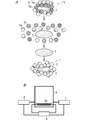
- FIG. 1A is an explanatory view of the manufacturing method of the glass panel unit concerning one embodiment.
- FIG. 1B is a conceptual diagram schematically showing an example of an apparatus used for manufacturing a getter material in the embodiment.
- FIG. 2A is a conceptual diagram schematically showing an example of a getter material according to the embodiment.
- FIG. 2B is a conceptual diagram specifically showing an aspect in which an adsorbing component is adsorbed in the above-described getter material.
- FIG. 2C is a conceptual diagram schematically showing another example of the getter material.
- FIG. 2D is a conceptual diagram specifically showing an aspect in which an adsorbing component is adsorbed in the above-described getter material.
- FIG. 1B is a conceptual diagram schematically showing an example of an apparatus used for manufacturing a getter material in the embodiment.
- FIG. 2A is a conceptual diagram schematically showing an example of a getter material according to the embodiment.
- FIG. 2B is a conceptual diagram specifically showing an aspect in which
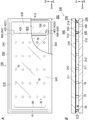
- FIG. 3A is a schematic plan view schematically showing an example of a temporary assembly according to the embodiment.
- FIG. 3B is a schematic cross-sectional view schematically showing a cross section of the temporary assembly.
- FIG. 4 is a schematic plan view schematically showing an example of the glass panel unit according to the embodiment.
- Drawing 5 is an explanatory view of the manufacturing method of the glass panel unit concerning an embodiment same as the above.
- Drawing 6 is an explanatory view of the manufacturing method of the glass panel unit concerning an embodiment same as the above.
- FIG. 7 is an explanatory diagram of a method for manufacturing the glass panel unit according to the embodiment.
- FIG. 8 is an explanatory diagram of a method for manufacturing the glass panel unit according to the embodiment.
- FIG. 10 is a flowchart schematically showing an example of a method for producing a getter material-containing composition according to an embodiment.
- a method for manufacturing a glass panel unit according to one embodiment (hereinafter sometimes simply referred to as a manufacturing method (M1)) will be described with reference to FIG. 1A to FIG.
- the manufacturing method (M1) includes a getter material main body generation step, a getter material preparation step, an assembly step, a frame body formation step, and an exhaust step.
- the retained component 5 held in the unprocessed getter material (initial getter material) 1a is vaporized and desorbed under heating, so that the getter material body 2 is solid remaining. It is the process of producing
- the holding component 5 includes a first holding component 5a and a second holding component 5b.
- the first holding component 5a is a component that is easily vaporized from the initial getter material 1a when the holding component 5 is detached.
- the second holding component 5b is a component that is less easily vaporized from the initial getter material 1a than the first holding component 5a when the holding component is desorbed.
- the aspect in which the second holding component 5b is held by the initial getter material 1a is considered to be due to the sintering process being performed in the presence of the second holding component 5b when the initial getter material 1a is manufactured. . Further, when the initial getter material 1a is stored for a long time in the presence of the second holding component 5b, even if the initial getter material 1a holds not only the second holding component 5b but also the first holding component 5a, the second holding component Since 5b has a higher affinity with the getter material body 2 than the first holding component 5a, the first holding component 5a is considered to be replaced with the second holding component 5b over time.
- the initial getter material 1a adsorbs and holds the second holding component 5b, the initial getter material 1a can be removed only by detaching the first holding component 5a that is easily vaporized from the initial getter material 1a. Gettering capability is not desirable in this embodiment.
- the first holding component 5a is adsorbed and held on the initial getter material 1a by physical adsorption.
- the first holding component 5a is held by the initial getter material 1a due to the interaction between one of the dipoles in the first holding component 5a and the charge of the initial getter material 1a.
- the second holding component 5b is adsorbed and held on the initial getter material 1a by chemical adsorption such as covalent bond and ionic bond.
- the initial getter material 1a is heated under conditions that allow the second holding component 5b to be vaporized and desorbed. That is, the first holding component 5a and the second holding component 5b are separated under the desorption conditions of the second holding component 5b.
- the temperature at which the initial getter material 1a is heated is higher than the exhaust temperature Te in the exhaust process described later.
- the initial getter material 1a is heated at a temperature of 350 ° C. or higher and 700 ° C. or lower, for example. Then, after the retention component 5 is detached, the getter material body 2 can be generated by exhausting the retention component 5.
- the first holding component 5a is vaporized and desorbed from the initial getter material 1a, for example, by heating the initial getter material 1a at 300 ° C. or lower.
- the first retention component 5a is vaporized and desorbed from the initial getter material 1a even when the initial getter material 1a is heated at a temperature higher than 300 ° C.
- the second holding component 5b is not detached only by heating the initial getter material 1a at 300 ° C. or lower, but is vaporized and detached from the initial getter material 1a by heating at a temperature higher than 350 ° C.
- Examples of the first holding component 5a include water, nitrogen, and carbon dioxide. Examples of the second holding component 5b include oxygen.
- the getter material main body generation step is performed in a chamber 6 as shown in FIG. 1B.
- maintenance component 5 can be made easy, and the getter material main body 2 can be easily produced
- the chamber 6 includes a heater 6a disposed on the position side. Both ends of the chamber 6 are connected to an exhaust pump 7 and a supply unit 8, respectively.
- the heater 6a, the exhaust pump 7, and the supply unit 8 are connected to the controller 9.
- the controller 9 When the controller 9 is connected to the heater 6a, the heater 6a heats the inside of the chamber 6 or stops the heat generation while its operation is controlled by the controller 9. Since the controller 9 is connected to the exhaust pump 7, the exhaust pump 7 decompresses the inside of the chamber 6 while its operation is controlled by the controller 9. Since the controller 9 is connected to the supply unit 8, the supply unit 8 supplies the adsorption component 3 into the chamber 6 while the operation is controlled by the controller 9.
- the holding component 5 may be exhausted out of the chamber 6 while the holding component 5 is desorbed by heating the initial getter material 1a.
- the inside of the chamber 6 is not limited to the decompression space, and may be an inert gas atmosphere.
- the inert gas can include at least one selected from the group consisting of neon, xenon, and argon, for example.
- the inside of the chamber 6 when the holding component 5 is desorbed is preferably a decompressed space, particularly preferably a vacuum space.
- the pressure in the chamber 6 may be, for example, 10 ⁇ 5 Pa to 0.1 Pa. Further, when the retained component 5 is exhausted out of the chamber 6, the operation of the supply unit 8 may be stopped.
- the chamber 6 is heated at a temperature at which the second holding component 5b is desorbed, so that the adsorption component 3 is hardly adsorbed by the getter material main body 2 at the temperature of the getter material main body generation step. For this reason, the getter material manufacturing step is performed after the getter material main body generating step.
- the adsorption component 3 may be supplied into the chamber 6 by operating the supply unit 8 during the getter material main body generation step. In this case, the adsorbing component 3 can be supplied into the chamber 6 by the supply unit 8 while the holding component 5 is exhausted out of the chamber 6 by the exhaust pump 7, so that the process period required for producing the getter material 1 can be shortened.
- the getter material production step is a step of producing the getter material 1 by adsorbing the adsorbing component 3 to the getter material main body 2.
- the adsorbed component 3 is a component that is easily vaporized at an exhaust temperature Te in an exhaust process described later.
- the getter material production process is also performed in the chamber 6.
- the adsorption component 3 is supplied into the chamber 6 by the supply unit 8. Thereby, the adsorption component 3 is adsorbed by the getter material body 2.
- the getter material 1 includes an adsorption component 3 and a main body (getter material main body) 2 as shown in FIG. 2A.
- the getter material body 2 is a solid residue obtained by vaporizing and desorbing the retained component 5 retained by the initial getter material 1a as described above (see FIG. 1A).
- the getter material body 2 adsorbs the adsorbing component 3 as shown in FIGS. 2A to 2B.
- each of FIGS. 2A to 2B exaggerates a mode in which the getter material body 2 adsorbs the adsorbing component 3.
- the getter material body 2 adsorbs the adsorption component 3 at the molecular level.
- the getter material body 2 may adsorb the adsorbing component 3 on the surface thereof.
- the getter material body 2 may adsorb the adsorbing component 3 through the pores 2a therein.
- the getter material body 2 may adsorb the adsorbing component 3 on the surface and the pores 2a.
- the getter material body 2 When the getter material body 2 has the pores 2a, the getter material body 2 is porous. That is, the getter material body 2 includes a plurality of pores 2a.
- a getter material body 2 has a zeolite structure 2z.
- one zeolite structure 2z is shown for easy understanding of the mode in which the adsorbing component 3 is adsorbed, but the getter material body 2 contains a plurality of zeolite structures 2z. In this case, adjacent zeolite structures 2z are three-dimensionally bonded. Thereby, the getter material main body 2 becomes porous containing a plurality of pores 2a.
- the zeolite structure 2z has a composition represented by the following general formula (1).
- Me is an x-valent cation present in the pore 2a.
- m is a silica / alumina ratio and is an integer of 2 or more.
- n is an integer of 0 or more.
- a monovalent negative charge is generated in each Al. Therefore, when Me is a divalent or higher cation, a positive charge is generated in the pore 2a.
- the pores 2a are electrically neutral.
- Me may be a monovalent cation.
- Me may be a divalent or higher cation.
- Me may be a combination of a monovalent cation and a divalent or higher cation.
- monovalent cations include alkali metal ions such as Li + , Na + , and K + ; protons; and ammonium ions (NH 4+ ).
- Divalent or higher cations include alkaline earth metal ions such as Ca 2+ , Mg 2+ and Ba 2+ ; and transition metal ions such as Cu 2+ , Au 2+ , Fe 2+ , Zn 2+ and Ni 2+ .
- Water (H 2 O) in the general formula (1) is contained in the zeolite structure 2z as crystal water. Such water is contained, for example, in the pores 2a. Further, when water in the zeolite structure 2z is dehydrated by heating or the like, the dehydrated zeolite structure 2z can improve hygroscopicity. When water in the zeolite structure 2z is completely dehydrated, n in the general formula (1) becomes 0.
- the getter material body 2 may be zeolite or copper ion exchanged zeolite.
- the zeolite is a component in which Me in the general formula (1) is a monovalent cation.
- a copper ion exchange zeolite is a component whose Me in General formula (1) is a copper ion.
- the copper ion exchanged zeolite is a component in which copper ions are held in the pores 2a.
- the “copper ion exchanged zeolite” is not limited to a specific type of zeolite before retaining copper ions in the pores 2a.
- the getter material body 2 is preferably made of a material that can adsorb nitrogen.
- the structure of the getter material body 2 is not limited to the A-type zeolite structure.
- the getter material body 2 can contain any zeolite structure such as an X-type zeolite structure, a Y-type zeolite structure, and a ZSM-5 structure.
- the adsorption component 3 is adsorbed on the getter material body 2 with a binding energy (BT1) equal to or lower than a predetermined temperature (Te) in terms of temperature. That is, the adsorbing component 3 is a component that has a binding energy (BT1) with the getter material body 2 equal to or lower than a predetermined temperature (Te) in terms of temperature, and desorbs when the getter material 1 is heated at the predetermined temperature (Te). is there. Thereby, the heating temperature for obtaining a predetermined gettering capability with the getter material 1 can be reduced.
- This predetermined temperature (Te) is an exhaust temperature Te described later.
- the adsorption component 3 is a component that is easily vaporized from the getter material body 2 by heating the getter material 1 at a temperature equal to or higher than the binding energy (BT1) in terms of temperature.
- the adsorbing component 3 may be any component as long as it is a component that does not chemically react with the getter material main body 2 and is adsorbed to the getter material main body 2 other than the second holding component 5b.
- Examples of the adsorbing component 3 include nitrogen, hydrogen, carbon dioxide, water, neon, xenon, hydrocarbons, and hydrocarbon derivatives.
- the hydrocarbon derivative include methanol, ethanol, and phenol. Of these, one or more components may be used.
- the binding energy (BT1) between the adsorbing component 3 and the getter material body 2 is not binding energy due to chemical adsorption such as covalent bond and ionic bond.
- the adsorbing component 3 is considered to be adsorbed to the getter material body 2 by physical adsorption, for example.
- the getter material body 2 is a porous portion having a large number of pores 2a as described above.
- the adsorption component 3 may be adsorbed on the getter material body 2 so as to fill the pores 2a in the getter material body 2.
- the adsorbing component 3 may be adsorbed on the getter material body 2 such that the adsorbing component 3 aggregates due to the charge in the pores 2a.
- the adsorbing component 3 becomes the getter material main body 2 due to the interaction between one of the dipoles in the adsorbing component 3 and the electric charge in the pore 2a. Is adsorbed on the surface.
- the adsorbing component 3 is not required to be chemically adsorbed to the getter material body 2, and the binding energy (BT1) between the adsorbing component 3 and the getter material body 2 is not particularly limited.
- the binding energy (BT1) is, for example, 300 ° C. or less in terms of temperature.
- the binding energy (BT1) is, for example, 200 ° C. or less.
- the binding energy (BT1) is, for example, 100 ° C. or higher.
- the getter material 1 vaporizes and desorbs the adsorbing component 3 from the getter material main body 2 at a temperature equal to or higher than the binding energy (BT1) in terms of temperature, whereby a gas component (G ) At least.
- BT1 binding energy
- G gas component
- the gas component (G) is, for example, a gas in a vacuum space 50 described later.
- the gas component (G) may be any gas that is adsorbed on the getter material body 2 after the adsorption component 3 is desorbed, and the specific compound name of the gas component (G) is not particularly limited.
- Examples of the gas component (G) include nitrogen, oxygen, carbon dioxide, water vapor, methane, ethane, neon, and xenon.
- the getter material 1 may further include a second adsorbing component 4 as shown in FIGS. 2C and 2D.
- the adsorption component 3 is the first adsorption component.
- the second adsorbing component 4 corresponds to oxygen in the air.
- the second adsorption component 4 is adsorbed on the getter material body 2 with a binding energy (BT2) at a temperature higher than the predetermined temperature Te in terms of temperature. That is, the second adsorbing component 4 has a binding energy (BT2) with the getter material body 2 that is higher than the predetermined temperature Te in terms of temperature, and does not leave even when the getter material body 2 is heated at the predetermined temperature Te. , A component that is detached when heated at a temperature higher than a predetermined temperature Te.
- the second adsorbing component 4 is a component that is less likely to vaporize and desorb from the getter material body 2 than the first adsorbing component 3 even when the getter material 1 is heated.
- the second adsorption component 4 is a trace component of the getter material 1.
- the second adsorbing component 4 may be adsorbed on the surface of the getter material body 2 as shown in FIG. 2C. Moreover, the 2nd adsorption
- the getter material 1 includes the first adsorbing component 3 and the second adsorbing component 4, the getter material 1 includes the first adsorbing component 3 in a larger content than the second adsorbing component 4.
- the second adsorbing component 4 is adsorbed on the getter material main body 2 as a trace component.
- the getter material 1 includes the second adsorption component 4 as described above, the first adsorption component of the getter material main body 2 can be obtained by storing the getter material 1 in a container filled with the same component as the first adsorption component 3. 3 can be made difficult to replace the second adsorbing component 4.
- the binding energy (BT2) between the second adsorbing component 4 and the getter material body 2 is not particularly limited.
- the binding energy (BT2) is, for example, a temperature higher than 300 ° C. in terms of temperature.
- the binding energy (BT2) is, for example, 400 ° C. or higher.
- the binding energy (BT2) is, for example, 450 ° C. or higher.
- the binding energy (BT2) is, for example, 700 ° C. or less.
- a mixture in which the second adsorbing component 4 is mixed with the first adsorbing component 3 may be supplied into the chamber 6 by the supply unit 8.
- the ratio of the first adsorbing component 3 is larger than that of the second adsorbing component 4.
- the second holding component 5b remaining as a trace component in the getter material main body 2 without being separated during the getter material main body generation step may be the second adsorption component 4.
- the second adsorption component 4 include oxygen.
- the getter material 1 according to the present embodiment includes the second adsorbing component 4 as a trace component, the amount of the getter material 1 used can be reduced, and the peripheral components of the getter material 1 can be hardly damaged at a relatively low temperature. Since the first adsorption component 3 can be desorbed, the high gettering capability of the getter material 1 can be realized.
- binding energy for example, a desorption peak temperature in a temperature programmed desorption analysis at a temperature rising rate of 5 ° C./min can be adopted.
- the manufacturing method (M1) further includes a getter material body cooling step.
- the getter material main body cooling step is performed between the getter material main body generation step and the getter material preparation step.
- the getter material body cooling step is a step of cooling the getter material body 2 after the retention component 5 is detached.
- the getter material main body cooling process the heat generation of the heater 6a is stopped. After stopping the heater 6 a, the adsorption component 3 is supplied from the supply unit 8, and the adsorption component 3 in the chamber 6 is exhausted out of the chamber 6 by the exhaust pump 7. Thereby, the inside of the chamber 6 can be cooled. Since the adsorption component 3 is supplied in the getter material main body cooling step, the getter material preparation step may be performed during the getter material main body cooling step.
- the chamber 6 may not be connected to the supply unit 8 when the adsorption component 3 is composed of a liquid component at room temperature and atmospheric pressure.
- the inside of the chamber 6 may be cooled, and the cooled getter material body 2 may be immersed in the liquid.
- the adsorption component 3 can be adsorbed to the getter material body 2.
- the getter material 1 may be dried so that the adsorption component 3 is not completely detached from the getter material body 2.
- the getter material 1 can adsorb at least a gas component (G) different from the adsorbed component 3 by vaporizing and desorbing the adsorbed component 3 from the getter material body 2 at a temperature equal to or higher than the binding energy (BT1) in terms of temperature. It is. As a result, the amount of getter material 1 used can be reduced, and the adsorbing component 3 can be desorbed at a relatively low temperature that makes it difficult to damage peripheral components of the getter material 1, so that high gettering capability of the getter material 1 can be realized. For this reason, the heating temperature for obtaining a predetermined gettering capability can be reduced, and a first melting temperature Tm1 and a second melting temperature Tm2 described later can be reduced. In other words, the getter material 1 can be suitably used even under conditions where the first melting temperature Tm1 and the second melting temperature Tm2 described later are low.
- the assembly process is a process for producing the temporary assembly 100 as shown in FIGS. 3A and 3B.
- the temporary assembly 100 is an intermediate body of the glass panel unit 10 as shown in FIG. 4 and is produced before the frame forming process.
- the thickness direction of the temporary assembly 100 and the glass panel unit 10 is defined as the D1 direction.
- a direction orthogonal to the D1 direction is defined as a D2 direction, and a direction orthogonal to the D2 direction is defined as a D3 direction.
- the D1 direction may be the first direction
- the D2 direction may be the second direction
- the D3 direction may be the third direction.
- the temporary assembly 100 includes a first glass plate 200, a second glass plate 300, a frame 410, an internal space 500, a partition 420, a ventilation path 600, an exhaust port 700, A gas adsorber 60 and a plurality of spacers 70 are provided.
- the first glass plate 200 includes a glass plate 210 as a main body and a coating 220. Note that the first glass plate 200 may not include the coating 220.
- the glass plate 210 is a rectangular flat plate and has a first surface 211 and a second surface 212.
- the first surface 211 is inside the temporary assembly 100 and the glass panel unit 10, and the second surface 212 is an exposed surface of the temporary assembly 100 and the glass panel unit 10.
- Each of the first surface 211 and the second surface 212 is a flat surface.
- the glass plate 210 may be any glass plate as long as it can be used in the manufacturing method (M3). Examples of the glass plate 210 include soda lime glass, high strain point glass, chemically tempered glass, alkali-free glass, quartz glass, neoceram, and physically tempered glass.
- the coating 220 is a film formed on the first surface 211.
- the coating 220 may be an infrared reflective film.
- the coating 220 is not limited to an infrared reflective film, and may be a film having desired physical characteristics.
- the second glass plate 300 includes a glass plate 310 that is a main body thereof.
- the glass plate 310 is a rectangular flat plate and has a first surface 311 and a second surface 312.
- the first surface 311 is inside the temporary assembly 100 and the glass panel unit 10
- the second surface 312 is an exposed surface of the temporary assembly 100 and the glass panel unit 10.
- Each of the first surface 311 and the second surface 312 is a flat surface.
- the planar shape of the glass plate 310 is the same as that of the glass plate 210. That is, the planar shape of the second glass plate 300 is the same as that of the first glass plate 200.
- the thickness of the glass plate 310 is the same as that of the glass plate 210.
- the glass plate 310 should just be able to be utilized for a manufacturing method (M3), and can employ
- the glass plate 310 is the same as the glass plate 210, for example.
- the second glass plate 300 may be composed only of the glass plate 310.
- the second glass plate 300 is disposed so as to face the first glass plate 200.
- the first surface 311 is opposed to the first surface 211.
- the 2nd glass plate 300 is parallel to the 1st glass plate 200, for example.
- the frame 410 is between the first glass plate 200 and the second glass plate 300 and is in contact with the first glass plate 200 and the second glass plate 300.
- the temporary assembly 100 includes an internal space 500 surrounded by the frame body 410, the first glass plate 200, and the second glass plate 300.
- the frame 410 is a frame-shaped hot-melt sealing material in which the thermal adhesive (A1) is disposed at both peripheral edges along the outer peripheral edge of the first glass plate 200 and the outer peripheral edge of the second glass plate 300. .
- the thermal adhesive (A1) is a first thermal adhesive having a first softening point.
- the first thermal adhesive contains glass frit.
- the first thermal adhesive is made of, for example, glass frit only.
- the glass frit is, for example, a low melting point glass frit. Examples of the low melting point glass frit include a bismuth glass frit, a lead glass frit, and a vanadium glass frit.
- the 1st thermal adhesive can contain 1 type, or 2 or more types of glass frit.
- the partition 420 is disposed in the internal space 500.
- the partition 420 partitions the internal space 500 into a first space 510 that becomes the vacuum space 50 by an exhaust process and a second space 520 that communicates with the exhaust port 700.
- the partition 420 includes a wall part 421 and a blocking part 422.
- the blocking unit 422 includes a first blocking unit 4221 and a second blocking unit 4222.
- the wall part 421 is formed along the direction D2.
- the exhaust port 700 is in a plane region surrounded by the wall portion 421 and the frame body 410.
- the D2 direction is, for example, the width direction of the second glass plate 300.
- both ends of the wall portion 421 are not in contact with the frame body 410 in the D2 direction.
- a first blocking portion 4221 is formed so as to extend from one end of the wall portion 421 toward the second space 520 from one end, and the second blocking portion 4222 extends from the other end toward the second space 520. Is formed.
- One end of the wall 421 may be a first end, and the other end may be a second end.
- the partition 420 is made of a thermal adhesive (A2).
- the thermal adhesive (A2) is a second thermal adhesive having a second softening point.
- the second thermal adhesive contains glass frit.
- the second thermal adhesive is made only of glass frit, for example.
- the glass frit is, for example, a low melting point glass frit. Examples of the low melting point glass frit include a bismuth glass frit, a lead glass frit, and a vanadium glass frit.
- the 2nd thermal adhesive agent can contain 1 type, or 2 or more types of glass frit.
- the second thermal adhesive is the same as the first thermal adhesive, for example. In this case, the second softening point is the same as the first softening point.
- the ventilation path 600 connects the first space 510 and the second space 520 in the internal space 500.
- the ventilation path 600 includes a first ventilation path 610 and a second ventilation path 620.
- the first air passage 610 is a space formed between the first blocking portion 4221 and the portion of the frame 410 that faces the first blocking portion 4221.
- the second ventilation path 620 is a space formed between the second blocking portion 4222 and the portion of the frame 410 that faces the second blocking portion 4222.
- the exhaust port 700 is a hole that connects the second space 520 and the external space.
- the exhaust port 700 is formed to exhaust the second space 520 and the first space 510 through the ventilation path 600.
- the exhaust port 700 is formed in the second glass plate 300 so as to connect the second space 520 and the external space.
- the exhaust port 700 is located at the corner of the second glass plate 300, for example.
- the gas adsorber 60 is disposed in the first space 510.
- the gas adsorber 60 has a long shape formed along the direction D2.
- the gas adsorber 60 is on the side opposite to the exhaust port 700 with respect to the wall 421 in the direction D3. That is, the gas adsorber 60 is disposed at the end of the first space 510 (vacuum space 50). In this way, the gas adsorber 60 can be made inconspicuous.
- the gas adsorber 60 is located away from the partition 420 and the ventilation path 600. For this reason, when the first space 510 is exhausted, the possibility that the gas adsorber 60 prevents the exhaust can be reduced.
- the gas adsorber 60 is used to absorb the residual gas existing in the vacuum space 50 after exhaust.
- the residual gas includes a gas released from the frame body 410, the partition 420, and the spacer 70 when the temporary assembly 100 is heated.
- the residual gas is adsorbed by the getter material 1 in the gas adsorber 60.
- the gas adsorber 60 contains the getter material 1 or the getter material-containing composition 1b.
- the getter material 1 has the property of releasing the adsorbed component 3 at a temperature equal to or higher than the binding energy (BT1) in terms of temperature.
- the gas adsorber 60 contains a powdered getter material 1.
- the gas adsorber 60 is formed, for example, by applying the getter material-containing composition 1 b to the second glass plate 300. In this case, the gas adsorber 60 can be made small. Therefore, the gas adsorber 60 can be disposed even if the vacuum space 50 is narrow.
- the getter material-containing composition 1b contains a volatile solvent
- the gas adsorber 60 is formed by removing the volatile solvent after coating. For this reason, the gas adsorber 60 contains components other than the volatile solvent in the getter material-containing composition 1b. That is, the gas adsorber 60 may be a dried product of the getter material-containing composition 1b.
- the plurality of spacers 70 are used to maintain the interval between the first glass plate 200 and the second glass plate 300 at a predetermined interval. That is, the plurality of spacers 70 are used to maintain the distance between the first glass panel 20 and the second glass panel 30 at a desired value.
- the plurality of spacers 70 are arranged in the first space 510. Specifically, the plurality of spacers 70 are arranged at intersections of virtual rectangular grids. The interval between the adjacent spacers 70 is 2 cm, for example.
- the spacer 70 only needs to maintain the distance between the first glass plate 200 and the second glass plate 300, and the size of the spacer 70, the number of the spacers 70, the distance between the spacers 70, and the arrangement position of the spacers 70 are appropriately selected. be able to.
- the spacer 70 has a cylindrical shape having a height substantially equal to the predetermined interval.
- the spacer 70 has a diameter of 0.5 mm and a height of 100 ⁇ m.
- each spacer 70 may have a desired shape such as a prismatic shape and a spherical shape.
- the spacer 70 may be transparent or opaque. In particular, when the spacer 70 is sufficiently small, the spacer 70 may be opaque.
- the material of the spacer 70 is selected so that the spacer 70 is not deformed in a first melting process, an exhaust process, and a second melting process, which will be described later.
- the material of the spacer 70 is selected, for example, so as to have a softening point (softening temperature) higher than the first softening point of the first thermal adhesive and the second softening point of the second thermal adhesive.
- a plurality of spacers 70 are formed in advance, and the plurality of spacers 70 can be arranged at predetermined positions on the second glass plate 300 using a chip mounter or the like. Further, the plurality of spacers 70 may be formed using a photolithography technique and an etching technique. In this case, the plurality of spacers 70 are formed by curing a photocurable resin, for example. Alternatively, the plurality of spacers 70 may be formed using a known thin film forming technique.
- a frame forming process is performed after the assembling process.
- the frame body forming step is a step of forming a frame body 411 that hermetically joins the first glass plate 200 and the second glass plate 300 by melting the frame body 410 by heating.
- the frame body 411 is a melt-cured product of the frame body 410. Specifically, the frame body 411 is a part obtained by melting and hardening the glass frit in the frame body 410.
- the frame forming process is a first melting process.
- the glass frit in the frame 410 is once melted at a temperature equal to or higher than the first softening point (first melting temperature) Tm1, so that the first glass plate 200 and the second glass plate 300 are hermetically sealed.
- the temporary assembly 100 is placed in a melting furnace and heated at a first melting temperature Tm1 for a first melting time tm1 (see FIG. 6).
- the first melting temperature Tm1 is higher than the temperature of the binding energy (BT1) converted in temperature.
- the adsorption component 3 can be released from the gas adsorber 60.
- the getter material 1 contains the second adsorbing component 4 as its trace component
- the first melting temperature Tm1 is lower than the temperature of the binding energy (BT2) in terms of temperature. It does not desorb from the gas adsorber 60.
- the first melting temperature Tm1 and the first melting time tm1 are set so that the glass frit in the frame 410 is melted, but the air passage 600 is not blocked by the partition 420. That is, the lower limit of the first melting temperature Tm1 is the first softening point, but the upper limit of the first melting temperature Tm1 is set so that the ventilation path 600 is not blocked by the partition 420. Further, if the second adsorbing component 4 is to be desorbed from the getter material 1 in the first melting step, the temperature needs to be increased and the air passage 600 is likely to be blocked. For this reason, in this embodiment, even if the getter material 1 contains the second adsorbing component 4 as its trace component, the temperature is suppressed and the second adsorbing component 4 is not released from the gas adsorbent 60.
- the first melting temperature Tm1 is set to 280 ° C.
- the first melting time tm1 is, for example, 10 minutes.
- the frame body 411 is formed by cooling and hardening the melted material of the frame body 410.
- gas is released from the frame 410, but this gas is exhausted by the exhausting step.
- the gas adsorber 60 is lower than the melting temperature of the glass glass frit in the frame 410 and at a predetermined temperature (exhaust temperature) Te while the internal space 500 is decompressed by exhausting through the exhaust port 700.
- a predetermined temperature exhaust temperature
- Heating the gas adsorber 60 during the exhaust process may make it difficult for the gas adsorber 60 to adsorb the gas released from the frame 410, the partition 420, and the spacer 70 in the first melting process and the exhaust process. it can.
- the gas released from the frame body 410, the partition 420, and the spacer 70 can be exhausted while the internal space 500 is decompressed.
- the first space 510 becomes the vacuum space 50 by exhausting the first space 510 through the ventilation path 600, the second space 520, and the exhaust port 700 at the exhaust temperature Te.
- the exhaust temperature Te is a temperature equal to or higher than the temperature of the converted energy (BT1). Therefore, the adsorption component 3 contained in the getter material 1 is separated from the getter material body 2 and exhausted, and the gettering ability of the getter material 1 can be enhanced. Even if the getter material 1 contains the second adsorption component 4 as its trace component, the exhaust temperature Te is set lower than the temperature of the binding energy (BT2) converted to temperature.
- the exhaust temperature Te may be a temperature at which the air passage 600 is not blocked even if the frame body 410 and the partition 420 are melted and crushed and spread, and can be the temperature at which the adsorption component 3 can be desorbed from the getter material 1.
- the exhaust temperature Te is, for example, 250 ° C.
- the exhaust process is performed using, for example, a vacuum pump.
- the vacuum pump is connected to the exhaust port 700 by an exhaust pipe 810 and a seal head 820.
- the exhaust pipe 810 is joined to the second glass plate 300 so as to communicate with the exhaust port 700.
- a seal head 820 is attached to the exhaust pipe 810, whereby the suction port of the vacuum pump is connected to the exhaust port 700.
- the frame body 411 and the partition 420 are not deformed.
- the temporary assembly 100 is heated without exhausting the internal space 500.
- the adsorption component 3 can be exhausted by heating the gas adsorbent 60 in the exhaust process. .
- the adsorbed component 3 from the gas adsorber 60 becomes a gas and is exhausted through the first space 510, the ventilation path 600, the second space 520, and the exhaust port 700.
- the exhaust time te of the exhaust process is set so that a vacuum space 50 with a predetermined degree of vacuum is obtained.
- the exhaust time te may be a time for setting the internal space 500 to the vacuum space 50, and the exhaust time te is not particularly limited.
- the exhaust time te is set to 120 minutes, for example.
- the adsorption component 3 When a part of the adsorption component 3 remains in the vacuum space 50 after the exhaust process, the adsorption component 3 is adsorbed on the getter material 1 as a residual gas.
- the manufacturing method (M3) further includes a second melting step.
- the second melting step is a step of forming the seal 40 that surrounds the vacuum space 50 by deforming the partition 420 to form the partition wall 42 that closes the ventilation path 600.
- the glass frit in the partition 420 is once melted at a second melting temperature Tm2 that is equal to or higher than the second softening point.
- Tm2 a second melting temperature
- the partition 420 is deformed to form the partition wall 42.
- the first glass plate 200 and the second glass plate 300 are heated in the melting furnace at the second melting temperature Tm2 for the second melting time tm2 (see FIG. 6).
- the second melting temperature Tm2 and the second melting time tm2 are set so that the glass frit in the partition 420 is melted and the partition wall 42 that blocks the air passage 600 is formed. Moreover, when the getter material 1 contains the 2nd adsorption component 4 as the trace component, 2nd melting temperature Tm2 may be higher than the temperature of the binding energy (BT2) converted into temperature. When the second melting temperature Tm2 is higher than the temperature of the binding energy (BT2), the second adsorption component 4 is released into the vacuum space 50. However, since the second adsorption component 4 is a trace component of the getter material 1, it is re-adsorbed to the getter material 1 after the second melting step.
- the gas is released from the frame body 410 or the partition 420 after the air passage 600 is closed, the gas is adsorbed by the getter material 1. Thereby, the deterioration of the vacuum degree in the vacuum space 50 can be suppressed. That is, the heat insulation of the glass panel unit 10 can be hardly lowered.
- the lower limit of the second melting temperature Tm2 is the second softening point (270 ° C.). Unlike the first melting step, the second melting step is intended to deform the partition 420, so the second melting temperature Tm2 is higher than the first melting temperature (280 ° C.) Tm1.
- the second melting temperature Tm2 is set to 300 ° C., for example.
- the second melting time tm2 is, for example, 30 minutes.
- the second melting temperature Tm2 may be set to the same temperature as the first melting temperature Tm1, and the pressure for crushing the frame body 410 and the partition 420 may be adjusted to block the ventilation path 600.
- a vacuum space 50 surrounded by the seal 40 including the partition wall 42 and the frame body 411 is formed. Since the vacuum space 50 is formed in a portion corresponding to the first space 510, the vacuum space 50 and the second space 520 are separated by the partition wall 42. That is, the partition wall 42 forms a boundary that separates the vacuum space 50 and a portion corresponding to the second space 520. Until the second melting step is completed, the frame body 411, the partition wall 42, and the spacer 70 are heated, and thus gas may be released from the frame body 411, the partition wall 42, and the spacer 70.
- the gas released from the frame body 411, the partition wall 42, and the spacer 70 is adsorbed by the gas adsorber 60 in the vacuum space 50. Therefore, deterioration of the degree of vacuum in the vacuum space 50 can be suppressed. That is, the heat insulation of the glass panel unit 10 can be hardly lowered.
- the exhaust process is continued, and the first space 510 is exhausted through the ventilation path 600, the second space 520, and the exhaust port 700. That is, in the second melting process, the partition 420 is deformed while the first space 510 is evacuated through the ventilation path 600, the second space 520, and the exhaust port 700 at the second melting temperature Tm2, and the ventilation path 600 is changed. A partition wall 42 for closing is formed. Thereby, the deterioration of the degree of vacuum in the vacuum space 50 can be further suppressed during the second melting step. Moreover, since the exhaust process is continued even when the air passage 600 is closed, the first space 510 is exhausted until just before the air passage 600 is closed, and the adsorbed component 3 is less likely to remain in the vacuum space 50 after the partition wall 42 is formed. .
- the vacuum degree of the vacuum space 50 is a predetermined value or less.
- the vacuum degree of the vacuum space 50 should just be hard to reduce the heat insulation of the glass panel unit 10, and a vacuum degree is not specifically limited.
- the degree of vacuum of the vacuum space 50 is, for example, 0.1 Pa.
- the seal 40 surrounds the vacuum space 50 and bonds the first glass plate 200 and the second glass plate 300 in an airtight manner.
- the seal 40 has a frame shape.
- the seal 40 has a first portion 41 and a second portion 42.
- the first portion 41 is a portion in contact with the vacuum space 50 in the frame body 411. That is, the first portion 41 is a portion of the frame 410 that faces the vacuum space 50.
- the first portion 41 constitutes three sides of the four sides of the seal 40 and is substantially U-shaped.
- the second portion 42 is a partition wall obtained by deforming the partition 420.
- the second portion 42 is I-shaped and constitutes the remaining one of the four sides of the seal 40.
- the glass panel unit 110 is manufactured by heating at the second melting temperature Tm2 and then cooling.
- the cooling in the second melting step may be any conditions as long as the molten glass frit can be sufficiently cured.
- the cooling in the second melting step may be natural cooling, for example, or may be cooling at a predetermined cooling rate.
- the manufacturing method (M3) further includes a cutting step.
- the cutting step is a step of cutting the glass panel unit 110 after the second melting step as shown in FIG.
- the portion having the vacuum space 50 and the portion (unnecessary portion) 11 having the second space 520 are divided. Of the parts divided in this manner, the part having the vacuum space 50 becomes the glass panel unit 10.
- the gas adsorber 60 contains the getter material 1
- the amount of use of the getter material 1 can be reduced, and components around the getter material 1 (for example, the first glass plate 200 and the first glass plate 200).
- the gettering ability can be realized at a relatively low temperature that makes it difficult to break the two glass plates 300). Therefore, the deterioration of the vacuum degree in the vacuum space 50 can be suppressed, and the heat insulation of the glass panel unit 10 can be made difficult to be lowered.
- said embodiment showed the example which used the getter material 1 for the glass panel unit 110, it can be used also for electronic devices, such as a MEMS apparatus and a display.
- the production method (M2) is a method for producing a composition 1b containing the getter material 1 as shown in FIG. For this reason, this embodiment can refer to the description of the getter material 1.
- the production method (M2) includes a solvent mixing step.
- the solvent mixing step is a step of mixing the getter material 1 and the solvent 1c.
- the production method (M2) can produce the getter material-containing composition 1b containing the getter material 1 and the solvent 1c.
- the getter material main body 2 becomes difficult to adsorb the second holding component 5b, so that the gettering ability of the getter material main body 2 can be maintained for a long period of time. Thereby, the stability of the getter material 1 can be improved.
- the solvent mixing step can employ any mixing method as long as the getter material 1 and the solvent 1c can be mixed.
- Examples of the mixing method in the solvent mixing step include three rolls, a ball mill, a sand mill, and paddle mixing.
- the solvent 1c may be any solvent as long as the stability of the getter material 1 can be improved.
- Examples of the solvent 1c include water, ethanol, and terpineol. Of these, one or more components may be used.
- an additive 1d such as a thickener and a filler may be further added during the solvent mixing step.
- the additive 1d When the additive 1d is added, the getter material 1, the solvent 1c, and the additive 1d can be mixed at the same time. Moreover, it is not necessary to add the additive 1d.
- the getter material-containing composition 1b can be used for producing the gas adsorbent 60 in the production method (M1).
- Example 1 0.2 g of copper ion exchanged zeolite (unheated) was placed in the chamber. After the zeolite was placed, the copper ion exchanged zeolite was heated at 450 ° C. for 1 hour while the chamber was evacuated to a vacuum space. As a result, the retained component retained in the copper ion exchanged zeolite was desorbed. After the heating, the inside of the chamber was cooled to room temperature. After cooling, nitrogen gas serving as an adsorbing component for the copper ion exchanged zeolite was flowed into the chamber, and the atmospheric pressure in the chamber was changed to atmospheric pressure. This produced the getter material.
- the getter material was once taken out of the chamber, imitating that the getter material was stored in the air, and then left in the air for 24 hours and returned to the chamber. Thereafter, the chamber was evacuated and the getter material was reheated at 300 ° C. for 1 hour to desorb nitrogen from the getter material.
- Example 2 A procedure similar to that in Example 1 was performed except that a getter material was produced by flowing nitrogen gas serving as an adsorbing component into the chamber, then the getter material was removed from the chamber, heated in the atmosphere at 300 ° C. for 15 minutes, and then returned to the chamber. Was done. The results are shown in Table 1 below. From this result, it can be seen that even if the getter material is heat-treated in the atmosphere at 300 ° C., a good gas adsorption characteristic can be obtained only by heat-treating at a low temperature in a vacuum thereafter.
- Example 3 0.2 g of copper ion exchanged zeolite (unheated) was placed in the chamber. After the zeolite was placed, the copper ion exchanged zeolite was heated at 450 ° C. for 1 hour while the chamber was evacuated to a vacuum space. As a result, the retained component retained in the copper ion exchanged zeolite was desorbed. After the heating, the inside of the chamber was cooled to room temperature. After cooling, nitrogen gas serving as an adsorbing component was poured into the copper ion-exchanged zeolite (getter material body) to produce a getter material and taken out from the chamber.
- getter material and water were mixed to adsorb moisture to the getter material, and a getter material solution (getter material-containing composition) using water as a solvent was prepared.
- this getter material-containing composition was dried in the air. After drying, the getter material which is the drying residue was placed in the chamber, the inside of the chamber was evacuated, and the getter material was reheated at 300 ° C. for 1 hour to desorb water and nitrogen from the getter material. .
- Solvent water, -Hot melt sealing material A; Vanadium glass frit, Hot melt sealing material B: Bismuth glass frit.
- the getter material was mixed with water to prepare a getter material-containing composition.
- a frame made of the hot-melt sealing material A, a partition made of the hot-melt sealing material A, an air passage, a gas adsorber, and a plurality of spacers are provided on one surface of the second glass plate having the exhaust port.
- the first glass plate was disposed so as to face the second glass plate.
- a temporary assembly product in which an internal space was formed between the first glass plate and the second glass plate was obtained.
- the getter material-containing composition was applied to the second glass plate so that the amount of getter material used was 0.1 g.
- the several spacer was arrange
- the temporary assembly was placed in the melting furnace. After this arrangement, the temporary assembly was heated at 280 ° C. (first melting temperature) for 15 minutes to once melt the glass frit of the frame. At the time of melting, the air passage was not blocked.
- the temperature in the melting furnace was lowered to 250 ° C., which is the exhaust temperature. And the internal space was exhausted at 250 degreeC for 120 minutes by operating a vacuum pump.
- the temperature in the melting furnace was raised to 290 ° C. which is the second melting temperature while the vacuum pump was operated, and the temporary assembly was heated at this temperature for 15 minutes. By this heating, the partition was deformed to form a partition wall blocking the air passage.
- the temperature in the melting furnace was lowered to room temperature. After this temperature decrease, the vacuum pump was stopped and the seal head was detached. After removing the seal head, unnecessary portions were removed by cutting to produce a glass panel unit.
- a frame made of the hot-melt sealing material B, a partition made of the hot-melt sealing material B, a vent, a gas adsorber, and a plurality of spacers are provided on one surface of the second glass plate having the exhaust port.
- the first glass plate was disposed so as to face the second glass plate.
- the getter material-containing composition was applied to the second glass plate so that the amount of getter material used was 0.1 g.
- the several spacer was arrange
- the temporary assembly was placed in the melting furnace. After this arrangement, the temporary assembly was heated at 450 ° C. (first melting temperature) for 10 minutes to once melt the glass frit of the frame. At the time of melting, the air passage was not blocked.
- the temperature in the melting furnace was lowered to 400 ° C., which is the exhaust temperature. And the internal space was exhausted at 400 degreeC for 120 minutes by operating a vacuum pump.
- the temperature in the melting furnace was raised to 460 ° C. which is the second melting temperature while the vacuum pump was operated, and the temporary assembly was heated at this temperature for 30 minutes. By this heating, the partition was deformed to form a partition wall blocking the air passage.
- the temperature in the melting furnace was lowered to room temperature. After this temperature decrease, the vacuum pump was stopped and the seal head was detached. After removing the seal head, unnecessary portions were removed by cutting to produce a glass panel unit.
- Reference Production Example 2 Reference Production Example 1 except that the hot melt sealing material A was used when the frame and the partition were provided, the first melting temperature was 280 ° C., the exhaust temperature was 250 ° C., and the second melting temperature was 290 ° C. Similarly, a glass panel unit was produced.
- Thermal conductance of the glass panel unit of each production example and reference production example was evaluated by the following procedure.
- the high temperature part and the low temperature part of the measuring device are partitioned by the glass panel unit, the first thermometer is arranged on the outer surface of the first glass plate, the second thermometer, the sensor, and the outer surface of the second glass plate Arranged.
- the heat flux transmitted from the heating unit to the cooling unit via the glass panel unit is detected by a sensor, the surface temperature of the first glass plate is measured by the first thermometer, and the second thermometer Then, the surface temperature of the second glass plate 2 was measured.
- the thermal conductance of the glass panel unit was calculated by introducing the heat flux, the surface temperature of the first glass plate, and the surface temperature of the second glass plate into the following formula (1).
- Q C (T1-T2) (1)
- Q represents the heat flux (W / m 2 )
- T1 represents the surface temperature (K) of the first glass plate
- T2 represents the surface temperature (K) of the second glass plate
- C Indicates thermal conductance (W / m 2 K).
- Thermal conductance of Production Example 1 is 5.0 W / m 2 K
- thermal conductance of preparation 2 is 0.8 W / m 2 K
- thermal conductance of Reference Production Example 1 In 0.8 W / m 2 K Yes, the thermal conductance of Reference Production Example 2 was 31 W / m 2 K.
- the first aspect is a method for manufacturing a glass panel unit (10), in which an untreated getter material (1a) is heated at a temperature higher than a predetermined temperature (Te) to obtain a getter material (1 ) And a step of manufacturing the temporary assembly (100).
- the temporary assembly (100) includes a first glass plate (200), a second glass plate (300), a frame-like hot melt sealing material (410), an internal space (500), and a gas adsorber (60). ) And an exhaust port (700).
- the second glass plate (300) is disposed so as to face the first glass plate (200).
- the frame-shaped hot-melt sealing material (410) is disposed between the first glass plate (200) and the second glass plate (300), and the first glass plate (200) and the second glass plate (300). Touching.
- the gas adsorber (60) contains the getter material (1) and is disposed in the internal space (500).
- the exhaust port (700) connects the internal space (500) and the external space.
- the manufacturing method of a 1st aspect is a frame (411) which airtightly joins to a 1st glass plate (200) and a 2nd glass plate (300) by fuse
- the manufacturing method of the first aspect further includes a step of heating the gas adsorbent (60) at a predetermined temperature (Te) while reducing the pressure of the internal space (500) by exhausting through the exhaust port (700). .
- the gas adsorber (60) contains the getter material (1), the amount of the getter material (1) used can be reduced, and the components around the getter material (1) are hardly damaged. Gettering capability can be achieved at relatively low temperatures.
- a 2nd aspect is a manufacturing method of the glass panel unit (10) of a 1st aspect, Comprising: A temporary assembly (100) is further provided with a partition (420) and a ventilation path (600).
- the partition (420) partitions the internal space (500) into a first space (510) and a second space (520) having an exhaust port (700).
- the ventilation path (600) connects the first space (510) and the second space (520).
- the partition (420) is deformed at a temperature higher than a predetermined temperature (Te) to form the partition (42) that closes the air passage (600), thereby the first partition (42).
- the method further includes a step of dividing the space (510) and the second space (520). In this step, after heating the gas adsorber (60), the internal space (500) is depressurized by exhausting it through the exhaust port (700).
- the degree of vacuum is deteriorated in the vacuum space (50) corresponding to the first space (510). Can be suppressed. That is, the amount of getter material (1) used in the vacuum space (50) can be reduced, and gettering ability can be realized at a relatively low temperature that makes it difficult to damage the components around the getter material (1).
- a 3rd aspect is a manufacturing method of the glass panel unit (10) of a 1st or 2nd aspect, Comprising:
- An untreated getter material (1a) is selected from the group which consists of neon, a xenon, and argon. Heating is performed under an inert gas atmosphere containing seeds or under reduced pressure.
- the amount of getter material (1) used can be reduced, and gettering ability can be realized at a relatively low temperature that makes it difficult to damage the components around the getter material (1).
- the fourth aspect is a method for producing the getter material (1), in which the retained component (5) retained in the untreated getter material (1a) is vaporized and desorbed under heating to produce an untreated getter. Generating the body (2) of the material (1a) as a solid remainder.
- the adsorption energy (3) whose binding energy with the main body (2) is not more than a predetermined temperature in terms of temperature is adsorbed to the main body (2), Producing a getter material (1).
- the getter material (1) can adsorb at least a gas component different from the adsorbing component (3) by vaporizing and desorbing the adsorbing component (3) at a temperature equal to or higher than the binding energy in terms of temperature.
- the amount of getter material (1) used can be reduced, and a getter material (1) that achieves gettering capability at a relatively low temperature that makes it difficult to damage components around the getter material (1) is obtained. be able to.
- the fifth aspect is a method for producing the getter material (1), which is a modification of the fourth aspect, in which the retained component (5) retained in the untreated getter material (1a) is removed under an inert gas atmosphere. Alternatively, heating under vacuum to vaporize and desorb to produce the untreated getter material (1a) body (2) as a solid remainder.
- the adsorption energy (3) whose binding energy with the main body (2) is not more than a predetermined temperature in terms of temperature is adsorbed to the main body (2), Producing a getter material (1).
- the getter material (1) can adsorb at least a gas component different from the adsorbing component (3) by vaporizing and desorbing the adsorbing component (3) at a temperature equal to or higher than the binding energy in terms of temperature.
- the amount of getter material (1) used can be reduced, and a getter material (1) that achieves gettering capability at a relatively low temperature that makes it difficult to damage the components around the getter material (1) is obtained. be able to.
- the sixth aspect is the method for producing the getter material (1) of the fourth aspect or the fifth aspect, wherein the adsorption component (3) is nitrogen, hydrogen, carbon dioxide, water, neon, xenon, hydrocarbon, and carbonization. At least one component selected from the group consisting of hydrogen derivatives.
- the amount of getter material (1) used can be reduced, and a getter material (1) that achieves gettering capability at a relatively low temperature that makes it difficult to damage components around the getter material (1) is obtained. be able to.
- the seventh aspect is a method for producing the getter material (1) according to any one of the fourth to sixth aspects, wherein the main body (2) is zeolite or copper ion exchanged zeolite.
- the amount of getter material (1) used can be reduced, and a getter material (1) that achieves gettering capability at a relatively low temperature that makes it difficult to damage components around the getter material (1) is obtained. be able to.
- the 8th aspect is a manufacturing method of a getter material containing composition (1b), Comprising: A getter material is mixed with a solvent.
- the getter material is a getter material (1) produced by the method for producing a getter material according to any one of the fourth to seventh aspects.
- a getter material-containing composition (1b) that can reduce the amount of getter material (1) used and achieve gettering capability at a relatively low temperature that makes it difficult to damage components around the getter material (1). ) Can be obtained.
- the ninth aspect is a getter material (1) and includes an adsorbing component (3) and a main body (2).
- the adsorbing component (3) is adsorbed in the main body (2).
- the adsorption component (3) is adsorbed on the main body (2) with a binding energy equal to or lower than a predetermined temperature in terms of temperature.
- the getter material (1) can adsorb at least a gas component different from the adsorbing component (3) by vaporizing and desorbing the adsorbing component (3) at a temperature equal to or higher than the binding energy in terms of temperature.
- the amount of getter material (1) used can be reduced, and gettering ability can be realized at a relatively low temperature that makes it difficult to damage the components around the getter material (1).
- the tenth aspect is the getter material (1) of the ninth aspect, and further includes a second adsorption component (4).
- the adsorption component (3) is a first adsorption component.
- the second adsorption component (4) is adsorbed on the main body (2) with a binding energy at a temperature higher than a predetermined temperature in terms of temperature.
- the getter material (1) contains the first adsorbing component (3) in a larger content than the second adsorbing component (4).
- the second adsorbing component (4) is adsorbed on the main body (2) as a trace component, the amount of the getter material (1) used can be reduced, and parts around the getter material (1) can be reduced. Gettering capability can be realized at a relatively low temperature that makes it difficult to break.
- the eleventh aspect is the getter material (1) of the ninth or tenth aspect, wherein the main body (2) vaporizes and desorbs the retained component (5) retained on the untreated getter material (1a). The remainder of the solid.
- the amount of getter material (1) used can be reduced, and gettering capability can be realized at a relatively low temperature that makes it difficult to damage the components around the getter material (1).
- a twelfth aspect is the getter material (1) according to any one of the ninth to eleventh aspects, wherein the adsorption component (3) includes nitrogen, hydrogen, carbon dioxide, water, neon, xenon, hydrocarbon, and carbonization. At least one component selected from the group consisting of hydrogen derivatives.
- the amount of getter material (1) used can be reduced, and gettering ability can be realized at a relatively low temperature that makes it difficult to damage the components around the getter material (1).
- the thirteenth aspect is the getter material (1) according to any one of the ninth to twelfth aspects, and the main body (2) is zeolite or copper ion exchanged zeolite.
- the amount of getter material (1) used can be reduced, and gettering ability can be realized at a relatively low temperature that makes it difficult to damage the components around the getter material (1).
- the 14th aspect is a manufacturing method of a getter material containing composition (1b), Comprising: A getter material is mixed with a solvent.
- the getter material is a getter material (1) produced by any one of the ninth to thirteenth aspects.
- a getter material-containing composition (1b) that can reduce the amount of getter material (1) used and realizes gettering ability at a relatively low temperature that makes it difficult to damage components around the getter material (1). ) Can be obtained.
Abstract
本開示は、ゲッタ材の使用量を軽減でき、ゲッタ材周辺の部品を破損させにくくする比較的低い温度でゲッタリング能力を実現できるガラスパネルユニットの製造方法を提供する。ガラスパネルユニットの製造方法は、未処理のゲッタ材1aを所定温度Teよりも高い温度で加熱して、ゲッタ材1を作製する工程と、第1ガラス板200と、第2ガラス板300と、枠状の熱溶融シール材410と、内部空間500と、ゲッタ材1を含有するガス吸着体60と、排気口700と、を備える仮組み立て品100を作製する工程と、加熱により熱溶融シール材410を溶融させることで第1ガラス板200と第2ガラス板300とに気密に接合する枠体411を形成する工程と、排気口700を介して排気することで内部空間500を減圧させながら、所定温度Teでガス吸着体60を加熱する工程と、を含む。
Description
本開示は、ゲッタ材、ゲッタ材の製造方法、ゲッタ材含有組成物の製造方法、及びガラスパネルユニットの製造方法に関する。より詳細には、本開示は、比較的低い温度でゲッタリング能力を実現することができるゲッタ材、ゲッタ材の製造方法、ゲッタ材含有組成物の製造方法、及びガラスパネルユニットの製造方法に関する。
従来、所定空間内でゼオライト等のゲッタ材にガス成分を吸着させることで、空間内のガス成分の量を減らすことが行われている。
このようなゲッタ材に関し、例えば、特許文献1には、ゼオライトと、無機バインダーとを含むゲッター組成物に熱処理をし、この熱処理により、無機バインダーを溶融させてゼオライトの表面に接着させると共に、ゼオライト中の揮発分を除去することで、ゼオライトのゲッタリング能力を向上させることが開示されている。
しかし、特許文献1のようなゲッタ材では、ゼオライトの表面が溶融した無機バインダーに接着している、すなわち、ゼオライトの表面の一部が無機バインダーにより覆われている。このため、空間内で十分なゲッタリング能力を実現させるには、空間内でのゲッタ材の使用量を増やすことが求められる。これにより、ゲッタ材のコストが増加しやすくなる。また、無機バインダーを溶融させることでゼオライト中の揮発分を除去させても、無機バインダーの溶融温度により、ゲッタ材周辺の部品が破損してしまう傾向がある。
本開示の目的は、ゲッタ材の使用量を軽減でき、ゲッタ材周辺の部品を破損させにくくする比較的低い温度でゲッタリング能力を実現できるゲッタ材、ゲッタ材の製造方法、ゲッタ材含有組成物の製造方法、及びガラスパネルユニットの製造方法を提供することである。
本開示に係る一態様は、ガラスパネルユニットの製造方法であって、未処理のゲッタ材を所定温度よりも高い温度で加熱して、ゲッタ材を作製する工程と、第1ガラス板と、前記第1ガラス板に対向するように配置された第2ガラス板と、前記第1ガラス板と前記第2ガラス板との間に配置されて前記第1ガラス板と前記第2ガラス板とに接触している枠状の熱溶融シール材と、前記第1ガラス板と前記第2ガラス板と前記枠状の熱溶融シール材とで囲まれた内部空間と、前記ゲッタ材を含有し、前記内部空間内に配置されたガス吸着体と、前記内部空間と外部空間とをつなぐ排気口と、を備える仮組み立て品を作製する工程と、加熱により前記枠状の熱溶融シール材を溶融させることで前記第1ガラス板と前記第2ガラス板とに気密に接合する枠体を形成する工程と、前記排気口を介して排気することで前記内部空間を減圧させながら、前記所定温度で前記ガス吸着体を加熱する工程と、を含む。
本開示に係る一態様は、ゲッタ材の製造方法であって、未処理のゲッタ材に保持されている保持成分を加熱下で気化及び脱離させて、前記未処理のゲッタ材の本体を固形の残部として生成することと、前記保持成分の脱離後、前記本体との結合エネルギーが、温度換算で、所定温度以下になる吸着成分を前記本体に吸着させることで、ゲッタ材を作製することと、を含む。前記ゲッタ材は、前記吸着成分を温度換算で前記結合エネルギー以上の温度で気化及び脱離させることにより、前記吸着成分とは別のガス成分を少なくとも吸着可能である。
本開示に係る一態様は、ゲッタ材含有組成物の製造方法であって、前記ゲッタ材の製造方法で作製された前記ゲッタ材を溶媒と混合することを含む。
本開示に係る一態様は、ゲッタ材であって、吸着成分と、前記吸着成分が吸着されている本体とを含む。前記吸着成分は、温度換算で所定温度以下の結合エネルギーで前記本体に吸着されている。前記ゲッタ材は、前記吸着成分を温度換算で前記結合エネルギー以上の温度で気化及び脱離させることにより、前記吸着成分とは別のガス成分を少なくとも吸着可能である。
本開示によれば、ゲッタ材の使用量を軽減でき、ゲッタ材周辺の部品を破損させにくくする比較的低い温度でゲッタリング能力を実現できる。
以下、本開示を実施するための形態を説明する。
<ガラスパネルユニットの製造方法>
一実施形態に係るガラスパネルユニットの製造方法(以下、単に製造方法(M1)という場合がある)を、図1A~図8を参照して説明する。
一実施形態に係るガラスパネルユニットの製造方法(以下、単に製造方法(M1)という場合がある)を、図1A~図8を参照して説明する。
製造方法(M1)は、ゲッタ材本体生成工程と、ゲッタ材作製工程と、組立工程と、枠体形成工程と、排気工程とを含む。
ゲッタ材本体生成工程は、図1Aのように、未処理のゲッタ材(初期ゲッタ材)1aに保持されている保持成分5を加熱下で気化及び脱離させて、ゲッタ材本体2を固形残部として生成する工程である。このため、初期ゲッタ材1aは、ゲッタ材本体2を得るための初期段階で利用される中間生成物である。
保持成分5は、第1保持成分5aと、第2保持成分5bとを含む。第1保持成分5aは、保持成分5を脱離させる際に初期ゲッタ材1aから容易に気化されやすい成分である。第2保持成分5bは、保持成分を脱離させる際に第1保持成分5aよりも初期ゲッタ材1aから気化されにくい成分である。
第2保持成分5bが初期ゲッタ材1aに保持されている態様は、初期ゲッタ材1aを作製する際に第2保持成分5bの存在下で焼結処理が行われていることに起因すると考えられる。さらに、初期ゲッタ材1aを第2保持成分5bの存在下で長期間保存すると、初期ゲッタ材1aが第2保持成分5bだけでなく第1保持成分5aを保持していても、第2保持成分5bは第1保持成分5aよりもゲッタ材本体2との親和性が高いため、第1保持成分5aは経時的に第2保持成分5bと置換されると考えられる。
このように、初期ゲッタ材1aは第2保持成分5bを吸着して保持しているため、初期ゲッタ材1aから気化されやすい第1保持成分5aを脱離させただけでは、初期ゲッタ材1aのゲッタリング能力は、本実施形態では望ましくない。
第1保持成分5aは、物理吸着により、初期ゲッタ材1aに吸着されて保持されていると考えられる。この場合、第1保持成分5a中の双極子のうち一方の単極子と、初期ゲッタ材1aの電荷との相互作用により、第1保持成分5aは初期ゲッタ材1aに保持されている。また、第2保持成分5bは、共有結合及びイオン結合等の化学吸着により、初期ゲッタ材1aに吸着されて保持されていると考えられる。
保持成分5を脱離させるにあたって、第2保持成分5bを気化及び脱離させることができる条件で初期ゲッタ材1aを加熱する。すなわち、第2保持成分5bの脱離条件の下で、第1保持成分5a及び第2保持成分5bを離脱させる。初期ゲッタ材1aを加熱する温度は、後述する排気工程の排気温度Teよりも高い。初期ゲッタ材1aは、例えば350℃超700℃以下の温度で加熱される。そして、保持成分5の脱離後、保持成分5を排気させることで、ゲッタ材本体2を生成することができる。第1保持成分5aは、例えば、初期ゲッタ材1aを300℃以下で加熱することで、初期ゲッタ材1aから気化して脱離する。この場合、第1保持成分5aは、初期ゲッタ材1aを300℃より高い温度で加熱しても、初期ゲッタ材1aから気化して脱離する。第2保持成分5bは、例えば、初期ゲッタ材1aを300℃以下で加熱するだけでは脱離せず、350℃より高い温度で加熱することで、初期ゲッタ材1aから気化して脱離する。
第1保持成分5aとして、例えば、水、窒素、及び二酸化炭素が挙げられる。第2保持成分5bとして、例えば、酸素が挙げられる。
本実施形態において、ゲッタ材本体生成工程は、図1Bのようなチャンバ6内で行われることが好ましい。これにより、保持成分5の脱離を容易にすることができ、脱離後の保持成分5をチャンバ6外へ排気することで、ゲッタ材本体2を容易に生成できる。
チャンバ6は、その位置側に配置されたヒータ6aを備える。チャンバ6の両端は、それぞれ排気ポンプ7と供給部8とに接続されている。そして、ヒータ6a、排気ポンプ7、及び供給部8は、コントローラ9に接続されている。
コントローラ9がヒータ6aに接続されていることで、ヒータ6aは、その動作がコントローラ9で制御されながら、チャンバ6内を加熱したり、発熱を停止したりする。コントローラ9が排気ポンプ7に接続されていることで、排気ポンプ7は、その動作がコントローラ9で制御されながら、チャンバ6内を減圧させる。コントローラ9が供給部8に接続されていることで、供給部8は、その動作がコントローラ9で制御されながら、吸着成分3をチャンバ6内に供給する。
ゲッタ材本体生成工程がチャンバ6内で行われることで、排気ポンプ7により、脱離後の保持成分5をチャンバ6外へ排気することができる。これにより、ゲッタ材本体2は、チャンバ6内で固形残部として生成される。ゲッタ材本体生成工程の際、初期ゲッタ材1aを加熱することで保持成分5を脱離させながら、保持成分5をチャンバ6外へ排気してもよい。この場合、チャンバ6内は、減圧空間に限らず、不活性ガスの雰囲気であってもよい。不活性ガスは、例えば、ネオン、キセノン、及びアルゴンからなる群から選択される少なくとも1種を含むことができる。保持成分5を脱離させる際のチャンバ6内は、好ましくは減圧空間であり、特に好ましくは真空空間である。
ゲッタ材本体生成工程の際、チャンバ6内の圧力は、例えば、10-5Pa以上0.1Pa以下であってもよい。また、保持成分5をチャンバ6外へ排気する際、供給部8の動作は停止していてもよい。
ゲッタ材本体生成工程ではチャンバ6内が第2保持成分5bを脱離させる温度で加熱されているため、ゲッタ材本体生成工程の温度で吸着成分3はゲッタ材本体2に吸着されにくい。このため、ゲッタ材作製工程は、ゲッタ材本体生成工程の後に行われる。しかし、ゲッタ材本体生成工程の際、供給部8を作動させて、吸着成分3をチャンバ6内に供給してもよい。この場合、排気ポンプ7で保持成分5をチャンバ6外に排気させながら、供給部8で吸着成分3をチャンバ6内に供給できるため、ゲッタ材1の作製に要する工程期間を短縮できる。
ゲッタ材作製工程は、吸着成分3をゲッタ材本体2に吸着させることで、ゲッタ材1を作製する工程である。吸着成分3は、後述する排気工程の排気温度Teで、容易に気化されやすい成分である。ゲッタ材本体生成工程がチャンバ6内で行われる場合、ゲッタ材作製工程もチャンバ6内で行われる。このため、吸着成分3は供給部8によりチャンバ6内に供給される。これにより、吸着成分3はゲッタ材本体2に吸着される。
ゲッタ材1は、図2Aのように、吸着成分3と、本体(ゲッタ材本体)2とを含む。
ゲッタ材本体2は、上記の通り、初期ゲッタ材1aに保持された保持成分5を気化及び脱離させた固形残部である(図1A参照)。
ゲッタ材本体2は、図2A~図2Bのように吸着成分3を吸着している。ここで、図2A~図2Bの各々は、ゲッタ材本体2が吸着成分3を吸着している態様を誇張している。具体的には、ゲッタ材本体2は、分子レベルの吸着成分3を吸着している。この場合、図2A及び図2Cのように、ゲッタ材本体2は、その表面に吸着成分3を吸着していてもよい。また、図2B及び図2Dのように、ゲッタ材本体2は、その中にある細孔2aで吸着成分3を吸着していてもよい。ゲッタ材本体2は、その表面及び細孔2aで吸着成分3を吸着していてもよい。
ゲッタ材本体2が細孔2aを備える場合、ゲッタ材本体2は多孔質である。すなわち、ゲッタ材本体2は複数の細孔2aを備える。このようなゲッタ材本体2は、ゼオライト構造2zを有する。図2B及び図2Dの例では、吸着成分3が吸着されている態様を分かりやすく説明するためにゼオライト構造2zを1つ示しているが、ゲッタ材本体2は複数のゼオライト構造2zを含有する。この場合、隣接するゼオライト構造2zが3次元的に結合している。これにより、ゲッタ材本体2は、複数の細孔2aを含有する多孔質となる。
ゼオライト構造2zは、下記一般式(1)の組成を有する。
Me2/XO・Al2O3・mSiO2・nH2O, …(1)
ここで、Meは細孔2a中に存在するx価のカチオンである。mはシリカ/アルミナ比であり、2以上の整数である。nは0以上の整数である。式(1)の組成中、各Alで1価の負電荷が生じている。このため、Meが2価以上のカチオンである場合、細孔2a内で正電荷が生じる。また、Meが1価のカチオンである場合、細孔2a内は電気的に中性となる。
Me2/XO・Al2O3・mSiO2・nH2O, …(1)
ここで、Meは細孔2a中に存在するx価のカチオンである。mはシリカ/アルミナ比であり、2以上の整数である。nは0以上の整数である。式(1)の組成中、各Alで1価の負電荷が生じている。このため、Meが2価以上のカチオンである場合、細孔2a内で正電荷が生じる。また、Meが1価のカチオンである場合、細孔2a内は電気的に中性となる。
ゼオライト構造2zでは、Meは1価のカチオンであってもよい。Meは2価以上のカチオンであってもよい。Meは1価のカチオンと、2価以上のカチオンを組み合わせていてもよい。1価のカチオンとして、例えば、Li+、Na+、及びK+等のアルカリ金属イオン;プロトン;並びにアンモニウムイオン(NH4+)が挙げられる。2価以上のカチオンとして、Ca2+、Mg2+、及びBa2+等のアルカリ土類金属イオン;並びにCu2+、Au2+、Fe2+、Zn2+及びNi2+等の遷移金属イオンが挙げられる。
一般式(1)中の水(H2O)は、結晶水としてゼオライト構造2zに含まれている。このような水は、例えば細孔2a内に含まれている。また、ゼオライト構造2z中の水を加熱等で脱水すると、脱水後のゼオライト構造2zは、吸湿性を向上させることができる。ゼオライト構造2z中の水を完全に脱水させた場合、一般式(1)中のnは0になる。
ゲッタ材本体2は、ゼオライト、又は銅イオン交換ゼオライトであってもよい。この場合、ゼオライトは、一般式(1)中のMeが1価のカチオンである成分である。また、銅イオン交換ゼオライトは、一般式(1)中のMeが銅イオンである成分である。ここで、銅イオン交換ゼオライトは、細孔2a内に銅イオンを保持させた成分である。このため「銅イオン交換ゼオライト」は、細孔2a内に銅イオンを保持させる前のゼオライトの具体的な種類まで限定しない。なおゲッタ材本体2は、窒素を吸着可能な材料を用いることが好ましい。
図2B及び図2Dの例では、A型ゼオライト構造を示しているが、ゲッタ材本体2の構造はA型ゼオライト構造だけに限定されない。ゲッタ材本体2は、X型ゼオライト構造、及びY型ゼオライト構造、及びZSM-5構造等の任意のゼオライト構造を含有できる。
吸着成分3は、温度換算で所定温度(Te)以下の結合エネルギー(BT1)でゲッタ材本体2に吸着されている。すなわち、吸着成分3は、ゲッタ材本体2との結合エネルギー(BT1)が温度換算で所定温度(Te)以下であり、ゲッタ材1を所定温度(Te)で加熱することにより脱離する成分である。これにより、ゲッタ材1で所定のゲッタリング能力を得るための加熱温度を低減できる。この所定温度(Te)は、後述の排気温度Teである。
吸着成分3は、温度換算で結合エネルギー(BT1)以上の温度でゲッタ材1を加熱することで、ゲッタ材本体2から容易に気化されやすい成分である。吸着成分3は、第2保持成分5b以外の、ゲッタ材本体2と化学反応しない成分で、かつゲッタ材本体2に吸着される成分であれば、吸着成分3は任意の成分であってもよい。吸着成分3としては、例えば、窒素、水素、二酸化炭素、水、ネオン、キセノン、炭化水素、及び炭化水素誘導体が挙げられる。炭化水素誘導体として、例えば、メタノール、エタノール、及びフェノールが挙げられる。これらのうち、1種又は2種以上の成分が用いられてもよい。
また、吸着成分3と、ゲッタ材本体2との結合エネルギー(BT1)は、共有結合及びイオン結合等の化学吸着による結合エネルギーでない。吸着成分3は、例えば、物理吸着でゲッタ材本体2に吸着されていると考えられる。
また、ゲッタ材本体2は、上記の通り、多数の細孔2aを有する多孔質の部位である。このため、吸着成分3は、ゲッタ材本体2中の細孔2aを満たすようにしてゲッタ材本体2に吸着されていてもよい。または、吸着成分3は、細孔2a中の電荷により吸着成分3が凝集するようにしてゲッタ材本体2に吸着されていてもよい。細孔2a中の電荷により吸着成分3が凝集する場合、吸着成分3中の双極子のうち一方の単極子と、細孔2a中の電荷との相互作用により、吸着成分3はゲッタ材本体2に吸着されている。
吸着成分3は、ゲッタ材本体2に化学吸着されていなければよく、吸着成分3とゲッタ材本体2との結合エネルギー(BT1)は特に限定されない。結合エネルギー(BT1)は、例えば、温度換算で300℃以下である。結合エネルギー(BT1)は、例えば、200℃以下である。結合エネルギー(BT1)は、例えば、100℃以上である。
本実施形態に係るゲッタ材1は、吸着成分3を温度換算で結合エネルギー(BT1)以上の温度でゲッタ材本体2から気化及び脱離させることにより、吸着成分3とは別のガス成分(G)を少なくとも吸着可能である。これにより、ゲッタ材1の使用量を軽減でき、ゲッタ材1の周辺部品を破損させにくくする比較的低い温度で吸着成分3を脱離できるため、ゲッタ材1の高いゲッタリング能力を実現できる。
ガス成分(G)は、例えば、後述の真空空間50にある気体である。ガス成分(G)は吸着成分3の脱離後のゲッタ材本体2に吸着される気体であればよく、ガス成分(G)の具体的な化合物名は特に限定されない。ガス成分(G)として、例えば、窒素、酸素、二酸化炭素、水蒸気、メタン、エタン、ネオン、及びキセノンなどが挙げられる。
また、ゲッタ材1は、図2C及び図2Dのように、第2吸着成分4を更に含んでもよい。このようにゲッタ材1が第2吸着成分4を含む場合、吸着成分3は第1吸着成分である。この第1吸着成分3の供給のため窒素を主成分とする空気を供給する場合、第2吸着成分4としては、空気中の酸素が相当する。
第2吸着成分4は、温度換算で所定温度Teよりも高い温度の結合エネルギー(BT2)でゲッタ材本体2に吸着されている。すなわち、第2吸着成分4は、ゲッタ材本体2との結合エネルギー(BT2)が温度換算で所定温度Teよりも高い温度であり、ゲッタ材本体2を所定温度Teで加熱しても離脱せず、所定温度Teより高い温度で加熱したときに離脱する成分である。第2吸着成分4は、ゲッタ材1を加熱しても、第1吸着成分3よりもゲッタ材本体2から気化及び脱離しにくい成分である。また、第2吸着成分4は、ゲッタ材1の微量成分である。
第2吸着成分4は、図2Cのようにゲッタ材本体2の表面で吸着されていてもよい。また、第2吸着成分4は、図2Dのように、ゲッタ材本体2の中にある細孔2aで吸着されていてもよい。第2吸着成分4は、ゲッタ材本体2の表面及び細孔2aで吸着されていてもよい。
ゲッタ材1が第1吸着成分3と、第2吸着成分4とを含む場合、ゲッタ材1は、第1吸着成分3を、第2吸着成分4よりも多い含有量で含む。この場合、ゲッタ材本体2に吸着されている成分のうち、第1吸着成分3の量が支配的であるため、第2吸着成分4は微量成分としてゲッタ材本体2に吸着されている。このようにゲッタ材1が第2吸着成分4を含む場合、ゲッタ材1を第1吸着成分3と同様の成分で満たされた容器内に保存することで、ゲッタ材本体2の第1吸着成分3を第2吸着成分4と置換させにくくできる。
第2吸着成分4は、共有結合及びイオン結合等の化学吸着により、ゲッタ材本体2に吸着されていると考えられる。第2吸着成分4とゲッタ材本体2との結合エネルギー(BT2)は特に限定されない。結合エネルギー(BT2)は、例えば、温度換算で300℃より高い温度である。結合エネルギー(BT2)は、例えば、400℃以上である。結合エネルギー(BT2)は、例えば、450℃以上である。結合エネルギー(BT2)は、例えば、700℃以下である。
ゲッタ材本体2に第2吸着成分4が吸着されている場合、第1吸着成分3に第2吸着成分4を混入させた混合物を供給部8でチャンバ6内に供給させてもよい。この場合、第1吸着成分3の割合が第2吸着成分4に対して多いことが望ましい。また、ゲッタ材本体生成工程の際に、離脱されずゲッタ材本体2に微量成分として残留した第2保持成分5bが第2吸着成分4であってもよい。第2吸着成分4として、例えば、酸素が挙げられる。
本実施形態に係るゲッタ材1は、微量成分として第2吸着成分4を含んでいても、ゲッタ材1の使用量を軽減でき、ゲッタ材1の周辺部品を破損させにくくする比較的低い温度で第1吸着成分3を脱離できるため、ゲッタ材1の高いゲッタリング能力を実現できる。
本実施形態に係る結合エネルギーは、例えば、昇温速度5℃/minでの昇温脱離分析における脱離ピーク温度を採用することができる。
製造方法(M1)は、ゲッタ材本体冷却工程を更に含む。ゲッタ材本体冷却工程は、ゲッタ材本体生成工程と、ゲッタ材作製工程との間で行われる。ゲッタ材本体冷却工程は、保持成分5の脱離後、ゲッタ材本体2を冷却する工程である。
ゲッタ材本体冷却工程では、ヒータ6aの発熱を停止させる。ヒータ6aの停止後、供給部8から吸着成分3を供給すると共に、チャンバ6内の吸着成分3を排気ポンプ7でチャンバ6外に排気する。これにより、チャンバ6内を冷却できる。ゲッタ材本体冷却工程では吸着成分3が供給されているため、ゲッタ材本体冷却工程の途中でゲッタ材作製工程が行われてもよい。
本実施形態では、吸着成分3が、室温及び大気圧下で液体の成分からなる場合、チャンバ6は供給部8に接続されていなくてもよい。この場合、ゲッタ材本体生成工程の後、チャンバ6内を冷却し、冷却後のゲッタ材本体2を上記の液体に浸してもよい。これにより、ゲッタ材本体2に吸着成分3を吸着させることができる。吸着成分3の吸着後、吸着成分3がゲッタ材本体2から完全には脱離しないようにしてゲッタ材1を乾燥させてもよい。
製造方法(M1)では、ゲッタ材1の作製後、このゲッタ材1を用いて、組立工程と、枠体形成工程と、排気工程とが行われる。
ゲッタ材1は、吸着成分3を温度換算で結合エネルギー(BT1)以上の温度でゲッタ材本体2から気化及び脱離させることにより、吸着成分3とは別のガス成分(G)を少なくとも吸着可能である。これにより、ゲッタ材1の使用量を軽減でき、ゲッタ材1の周辺部品を破損させにくくする比較的低い温度で吸着成分3を脱離できるため、ゲッタ材1の高いゲッタリング能力を実現できる。このため、所定のゲッタリング能力を得るための加熱温度を低減でき、後述の第1溶融温度Tm1及び第2溶融温度Tm2を低減できる。言い換えると、ゲッタ材1は、後述の第1溶融温度Tm1及び第2溶融温度Tm2が低い条件でも好適に利用できる。
組立工程は、図3A及び図3Bのような仮組み立て品100を作製する工程である。仮組み立て品100は、図4のようなガラスパネルユニット10の中間体であって、枠体形成工程の前に作製される。
また、本実施形態の説明を簡潔にするため、仮組み立て品100、及びガラスパネルユニット10の厚み方向をD1方向とする。D1方向と直交する方向をD2方向とし、D2方向と直交する方向をD3方向とする。また、D1方向は第1方向であってもよく、D2方向は第2方向であってもよく、そしてD3方向は第3方向であってもよい。
仮組立て品100は、図3Aのように、第1ガラス板200と、第2ガラス板300と、枠体410と、内部空間500と、仕切り420と、通気路600と、排気口700と、ガス吸着体60と、複数のスペーサ70と、を備える。
第1ガラス板200は、その本体であるガラス板210と、コーティング220と、を備える。なお、第1ガラス板200はコーティング220を備えなくてもよい。
ガラス板210は、矩形状の平板であり、第1面211、及び第2面212を有する。第1面211は、仮組み立て品100、及びガラスパネルユニット10の内側にあり、第2面212は、仮組み立て品100、及びガラスパネルユニット10の露出面である。第1面211、及び第2面212の各々は、平面である。ガラス板210は、製造方法(M3)に利用できればよく、任意のガラス板を採用できる。ガラス板210として、例えば、ソーダライムガラス、高歪点ガラス、化学強化ガラス、無アルカリガラス、石英ガラス、ネオセラム、及び物理強化ガラスが挙げられる。
コーティング220は、第1面211に形成される皮膜である。コーティング220は、赤外線反射膜であってもよい。本実施形態では、コーティング220は、赤外線反射膜に限定されず、所望の物理特性を有する皮膜であってもよい。
第2ガラス板300は、その本体であるガラス板310を備える。ガラス板310は、矩形状の平板であり、第1面311、及び第2面312を有する。第1面311は、仮組み立て品100、及びガラスパネルユニット10の内側にあり、第2面312は、仮組み立て品100、及びガラスパネルユニット10の露出面である。第1面311、及び第2面312の各々は、平面である。
ガラス板310の平面形状は、ガラス板210と同じである。すなわち、第2ガラス板300の平面形状は、第1ガラス板200と同じである。また、ガラス板310の厚みは、ガラス板210と同じである。ガラス板310は、製造方法(M3)に利用できればよく、任意のガラス板を採用できる。ガラス板310として、例えば、ソーダライムガラス、高歪点ガラス、化学強化ガラス、無アルカリガラス、石英ガラス、ネオセラム、及び物理強化ガラスが挙げられる。ガラス板310は、例えば、ガラス板210と同じである。
第2ガラス板300は、ガラス板310のみから構成されてもよい。第2ガラス板300は、第1ガラス板200と対向するようにして配置されている。この場合、第1面311は、第1面211と対向している。また、第2ガラス板300は、例えば、第1ガラス板200と平行である。
枠体410は、第1ガラス板200と第2ガラス板300との間にあり、第1ガラス板200と第2ガラス板300とに接触している。これにより、仮組み立て品100は、枠体410と、第1ガラス板200と、第2ガラス板300とに囲まれた内部空間500を備える。
枠体410は、熱接着剤(A1)が第1ガラス板200の外周縁と、第2ガラス板300の外周縁とに沿った両周縁部に配置された枠状の熱溶融シール材である。熱接着剤(A1)は、第1軟化点を有する第1熱接着剤である。第1熱接着剤は、ガラスフリットを含有する。第1熱接着剤は、例えば、ガラスフリットのみからなる。ガラスフリットは、例えば、低融点ガラスフリットである。低融点ガラスフリットとしては、例えば、ビスマス系ガラスフリット、鉛系ガラスフリット、及びバナジウム系ガラスフリットである。これらのうち、1種又は2種以上のガラスフリットを第1熱接着剤は含有できる。
仕切り420は、内部空間500内に配置される。仕切り420は、内部空間500を、排気工程により真空空間50となる第1空間510と、排気口700と通じる第2空間520とに仕切る。
仕切り420は、壁部421と、遮断部422とを備える。遮断部422は、第1遮断部4221と、第2遮断部4222とを備える。壁部421は、D2方向に沿って形成されている。この場合、壁部421と、枠体410とで囲まれた平面領域内に排気口700がある。また、D2方向は、例えば、第2ガラス板300の幅方向である。また、D2方向において、壁部421の両端は、枠体410と接触していない。壁部421の両端のうち、一端から第2空間520に向かって延びるようにして第1遮断部4221が形成され、他端から第2空間520に向かって延びるようにして第2遮断部4222が形成されている。壁部421の一端は第1端であってもよく、他端は第2端であってもよい。
仕切り420は、熱接着剤(A2)からなる。熱接着剤(A2)は、第2軟化点を有する第2熱接着剤である。第2熱接着剤は、ガラスフリットを含有する。第2熱接着剤は、例えば、ガラスフリットのみからなる。ガラスフリットは、例えば、低融点ガラスフリットである。低融点ガラスフリットとしては、例えば、ビスマス系ガラスフリット、鉛系ガラスフリット、及びバナジウム系ガラスフリットが挙げられる。これらのうち、1種又は2種以上のガラスフリットを第2熱接着剤は含有できる。また、第2熱接着剤は例えば、第1熱接着剤と同じである。この場合、第2軟化点は第1軟化点と同じである。
通気路600は、内部空間500内で第1空間510と第2空間520とをつなぐ。通気路600は、第1通気路610と、第2通気路620と、を備える。第1通気路610は、第1遮断部4221と、第1遮断部4221に対向する枠体410の部分との間に形成された空間である。第2通気路620は、第2遮断部4222と、第2遮断部4222に対向する枠体410の部分との間に形成された空間である。
排気口700は、第2空間520と外部空間とをつなぐ孔である。排気口700は、第2空間520と、通気路600を介して第1空間510とを排気するために形成されている。排気口700は、第2空間520と外部空間とをつなぐように第2ガラス板300に形成されている。排気口700は、例えば、第2ガラス板300の角部分に位置している。
ガス吸着体60は、第1空間510内に配置される。具体的には、ガス吸着体60は、D2方向に沿って形成された長尺状である。ガス吸着体60は、D3方向において、壁部421に対して排気口700とは反対側にある。つまり、ガス吸着体60は、第1空間510(真空空間50)の端に配置される。このようにすれば、ガス吸着体60を目立たなくすることができる。また、ガス吸着体60は、仕切り420、及び通気路600から離れた位置にある。そのため、第1空間510の排気時に、ガス吸着体60が排気を妨げる可能性を低くできる。
ガス吸着体60は、排気後の真空空間50に存在する残留ガスを吸収するために用いられる。残留ガスは、仮組み立て品100が加熱された際に、枠体410、仕切り420、及びスペーサ70から放出されるガスを含む。残留ガスは、ガス吸着体60中のゲッタ材1に吸着される。
ガス吸着体60は、ゲッタ材1、又はゲッタ材含有組成物1bを含有する。ゲッタ材1は、温度換算で結合エネルギー(BT1)以上の温度で、吸着成分3を放出する性質を有している。
ガス吸着体60は、粉体のゲッタ材1を含有する。ガス吸着体60は、例えば、ゲッタ材含有組成物1bを第2ガラス板300に塗布することにより形成される。この場合、ガス吸着体60を小さくできる。したがって、真空空間50が狭くてもガス吸着体60を配置できる。また、ゲッタ材含有組成物1bが揮発性の溶媒を含有する場合、塗布後、揮発性溶媒を除去させてガス吸着体60を形成する。このため、ガス吸着体60は、ゲッタ材含有組成物1bのうち、揮発性溶媒以外の成分を含有する。すなわち、ガス吸着体60は、ゲッタ材含有組成物1bの乾燥物であってもよい。
複数のスペーサ70は、第1ガラス板200と第2ガラス板300との間隔を所定間隔に維持するために用いられる。つまり、複数のスペーサ70は、第1ガラスパネル20と第2ガラスパネル30との距離を所望の値に維持するために使用される。
複数のスペーサ70は、第1空間510内に配置されている。具体的には、複数のスペーサ70は、仮想的な矩形状の格子の交差点に配置されている。隣接するスペーサ70の間隔は、例えば2cmである。スペーサ70は、第1ガラス板200と第2ガラス板300との間隔を維持できればよく、スペーサ70の大きさ、スペーサ70の数、スペーサ70の間隔、及びスペーサ70の配置位置は、適宜選択することができる。
スペーサ70は、上記所定間隔とほぼ等しい高さを有する円柱状である。スペーサ70は、例えば、直径が0.5mm、高さが100μmである。また、各スペーサ70は、角柱状、及び球状等の所望の形状であってもよい。
スペーサ70は、透明であってもよく、不透明であってもよい。特にスペーサ70が十分に小さい場合、スペーサ70は不透明であってもよい。スペーサ70の材料は、後述する第1溶融工程、排気工程、第2溶融工程において、スペーサ70が変形しないように選択される。スペーサ70の材料は、例えば、第1熱接着剤の第1軟化点および第2熱接着剤の第2軟化点よりも高い軟化点(軟化温度)を有するように選択される。
スペーサ70を形成するにあたって、例えば、複数のスペーサ70を予め形成しておき、チップマウンタなどを利用して、複数のスペーサ70を、第2ガラス板300の所定位置に配置することができる。また、複数のスペーサ70は、フォトリソグラフィ技術、及びエッチング技術を利用して形成されていてもよい。この場合、複数のスペーサ70は、例えば、光硬化性樹脂を硬化させて形成される。あるいは、複数のスペーサ70は、周知の薄膜形成技術を利用して形成されていてもよい。
製造方法(M3)では、組立工程後、枠体形成工程が行われる。
枠体形成工程は、加熱により枠体410を溶融させることで第1ガラス板200と第2ガラス板300とを気密に接合する枠体411を形成する工程である。枠体411は、枠体410の溶融硬化物である。具体的には、枠体411は、枠体410中のガラスフリットを溶融硬化させた部位である。
枠体形成工程は、第1溶融工程である。第1溶融工程では、第1軟化点以上の温度(第1溶融温度)Tm1で枠体410中のガラスフリットを一旦溶融させることで、第1ガラス板200と第2ガラス板300とを気密に接合する。具体的には、仮組み立て品100は、溶融炉内に配置され、第1溶融温度Tm1で第1溶融時間tm1の間加熱される(図6参照)。第1溶融温度Tm1は、温度換算した結合エネルギー(BT1)の温度よりも高い。これにより、吸着成分3をガス吸着体60から放出させることができる。また、ゲッタ材1がその微量成分として第2吸着成分4を含有している場合、第1溶融温度Tm1は、温度換算した結合エネルギー(BT2)の温度よりも低いため、第2吸着成分4はガス吸着体60から脱離しない。
第1溶融温度Tm1、及び第1溶融時間tm1は、枠体410中のガラスフリットを溶融させるが、仕切り420によって通気路600が塞がれることがないように、設定される。つまり、第1溶融温度Tm1の下限は、第1軟化点であるが、第1溶融温度Tm1の上限は、仕切り420によって通気路600が塞がれることがないように設定される。また、第1溶融工程において第2吸着成分4をゲッタ材1から脱離させようとすると、温度を高める必要があり通気路600は塞がりやすい。このため、本実施形態では、ゲッタ材1がその微量成分として第2吸着成分4を含有していても温度を抑え、第2吸着成分4をガス吸着体60から放出させることは行わない。
第1溶融工程で枠体410中のガラスフリットを溶融させるにあたって、例えば、第1軟化点、及び第2軟化点が270℃である場合、第1溶融温度Tm1は、280℃に設定される。また、第1溶融時間tm1は、例えば、10分である。
第1溶融工程中、枠体410の溶融化物を冷却して硬化させることで、枠体411が形成される。第1溶融工程では、枠体410からガスが放出されるが、このガスは排気工程により排気される。
排気工程は、排気口700を介して排気することで内部空間500を減圧させながら、枠体410中のガラスガラスフリットの溶融温度よりも低く、かつ所定温度(排気温度)Teでガス吸着体60を加熱する工程である。排気工程中、ガス吸着体60を加熱することで、第1溶融工程、及び排気工程で枠体410、仕切り420、及びスペーサ70から放出されたガスをガス吸着体60に吸着させにくくさせることができる。さらに、排気口700を介して排気することで、内部空間500を減圧させながら、枠体410、仕切り420、及びスペーサ70から放出されたガスを排気することができる。排気工程中、排気温度Teで、通気路600、第2空間520、及び排気口700を介して第1空間510を排気することで、第1空間510は真空空間50となる。排気温度Teは、温度換算した結合エネルギー(BT1)の温度以上の温度である。そのため、ゲッタ材1に含有される吸着成分3は、ゲッタ材本体2から離脱して排気され、ゲッタ材1のゲッタリング能力を高めることができる。また、ゲッタ材1がその微量成分として第2吸着成分4を含有している場合であっても、排気温度Teは、温度換算した結合エネルギー(BT2)の温度よりも低くする。排気温度Teは、枠体410および仕切り420が溶融して潰れ広がっても通気路600が塞がれない温度であって、ゲッタ材1から吸着成分3が脱離できる温度であればよい。排気温度Teは、例えば、250℃である。
排気工程は、例えば、真空ポンプを用いて行われる。真空ポンプは、図5のように、排気管810と、シールヘッド820と、により排気口700に接続される。排気管810は、排気口700と連通するようにして第2ガラス板300に接合される。そして、排気管810にシールヘッド820が取り付けられ、これによって、真空ポンプの吸気口が排気口700に接続される。
排気工程中、枠体411、及び仕切り420は変形しない。また、第1溶融工程においては、内部空間500を排気せずに仮組み立て品100を加熱しているが、排気工程でもガス吸着体60を加熱することにより、吸着成分3を排気させることができる。この場合、ガス吸着体60からの吸着成分3は、ガスとなって、第1空間510、通気路600、第2空間520、及び排気口700を通じて排気される。
排気工程の排気時間teは、所定の真空度の真空空間50が得られるように設定される。排気時間teは、内部空間500を真空空間50にする時間であればよく、排気時間teは特に限定されない。排気時間teは、例えば、120分に設定される。
排気工程後、吸着成分3の一部が真空空間50内に残留した場合、この吸着成分3は残留ガスとしてゲッタ材1に吸着される。
製造方法(M3)は、第2溶融工程を更に含む。
第2溶融工程は、仕切り420を変形させて、通気路600を塞ぐ隔壁42を形成することで、真空空間50を囲むシール40を形成する工程である。第2溶融工程では、第2軟化点以上の第2溶融温度Tm2で仕切り420中のガラスフリットを一旦溶融させる。これにより、仕切り420を変形させて隔壁42を形成する。具体的には、第1ガラス板200、及び第2ガラス板300は、溶融炉内で、第2溶融温度Tm2で第2溶融時間tm2の間、加熱される(図6参照)。
第2溶融温度Tm2、及び第2溶融時間tm2は、仕切り420中のガラスフリットを溶融させ、通気路600を塞ぐ隔壁42が形成されるように設定される。また、ゲッタ材1がその微量成分として第2吸着成分4を含有している場合、第2溶融温度Tm2は、温度換算した結合エネルギー(BT2)の温度よりも高くてもよい。第2溶融温度Tm2が結合エネルギー(BT2)の温度よりも高い場合、真空空間50内に第2吸着成分4が放出される。しかし、第2吸着成分4は、ゲッタ材1の微量成分であるため、第2溶融工程後、ゲッタ材1に再吸着される。また、通気路600が塞がった後に、枠体410や仕切り420からガスが放出されても、このガスはゲッタ材1に吸着される。これにより、真空空間50における真空度の悪化を抑制することができる。つまり、ガラスパネルユニット10の断熱性を低下させにくくできる。
第2溶融温度Tm2の下限は、第2軟化点(270℃)である。第2溶融工程では、第1溶融工程とは異なり、仕切り420を変形させることを目的としているから、第2溶融温度Tm2は、第1溶融温度(280℃)Tm1より高くしている。第2溶融温度Tm2は、例えば、300℃に設定される。また、第2溶融時間tm2は、例えば、30分である。なお、第2溶融温度Tm2を第1溶融温度Tm1と同じ温度で行い、枠体410および仕切り420を潰す圧力を調整して、通気路600を塞ぐようにしてもよい。
図7のような隔壁42が形成されると、隔壁42と、枠体411とからなるシール40に囲まれた真空空間50が形成される。真空空間50は、第1空間510に対応する部分に形成されているため、隔壁42で、真空空間50と第2空間520とを区分する。すなわち、隔壁42は、真空空間50と、第2空間520に対応する部分とを区分する境界を構成する。第2溶融工程が終了するまでは、枠体411、隔壁42、及びスペーサ70が加熱されているから、枠体411、隔壁42、及びスペーサ70からガスが放出されることがある。しかしながら、枠体411、隔壁42、及びスペーサ70から放出されたガスは、真空空間50内のガス吸着体60に吸着される。そのため、真空空間50における真空度の悪化を抑制することができる。つまり、ガラスパネルユニット10の断熱性を低下させにくくできる。
また、第2溶融工程では、排気工程を継続して、通気路600と第2空間520と排気口700とを介して第1空間510を排気する。つまり、第2溶融工程では、第2溶融温度Tm2で、通気路600と第2空間520と排気口700とを介して第1空間510を排気しながら、仕切り420を変形させて通気路600を塞ぐ隔壁42を形成する。これによって、第2溶融工程中に、真空空間50における真空度の悪化をさらに抑制できる。しかも、通気路600を塞いでも排気工程が継続されるため、通気路600を塞ぐ直前まで第1空間510が排気され、隔壁42の形成後、吸着成分3も真空空間50中に残留しにくくなる。
真空空間50は、その真空度が所定値以下である。真空空間50の真空度は、ガラスパネルユニット10の断熱性を低下させにくくできればよく、真空度は特に限定されない。真空空間50の真空度は、例えば、たとえば、0.1Paである。
シール40は、真空空間50を囲むとともに、第1ガラス板200と第2ガラス板300とを気密に接合する。シール40は、枠状である。シール40は、第1部分41と、第2部分42と、を有する。第1部分41は、枠体411のうち、真空空間50と接する部分である。つまり、第1部分41は、枠体410のうち、真空空間50に面している部分である。第1部分41は、シール40の四辺のうちの三辺を構成し、略U字状である。第2部分42は、仕切り420を変形することで得られる隔壁である。第2部分42は、I字状であり、シール40の四辺のうちの残りの一辺を構成する。
第2溶融工程中、第2溶融温度Tm2で加熱後、冷却してガラスパネルユニット110を作製する。第2溶融工程の冷却は、溶融したガラスフリットを十分に硬化させることができればよく、任意の条件を採用できる。第2溶融工程の冷却は、例えば、自然放冷であってもよく、或いは、所定の冷却速度での冷却であってもよい。
製造方法(M3)は、切断工程を更に含む。
切断工程は、第2溶融工程後のガラスパネルユニット110を、図8のように切断する工程である。切断工程により、真空空間50を有する部分と、第2空間520を有する部分(不要な部分)11とが分断される。このようにして分断された部分のうち、真空空間50を有する部分は、ガラスパネルユニット10となる。
製造方法(M3)によれば、ガス吸着体60がゲッタ材1を含有することで、ゲッタ材1の使用量を軽減でき、ゲッタ材1周辺の部品(例えば、第1ガラス板200、及び第2ガラス板300)を破損させにくくする比較的低い温度でゲッタリング能力を実現できる。そのため、真空空間50における真空度の悪化を抑制することができ、ガラスパネルユニット10の断熱性を低下させにくくすることができる。
なお、上記の実施形態は、ゲッタ材1をガラスパネルユニット110に用いた例を示したが、MEMS機器やディスプレイ等の電子機器にも使用することができる。
<ゲッタ材含有組成物の製造方法>
次に、ゲッタ材含有組成物の製造方法(以下、単に製造方法(M2)という場合がある)を、図10を参照して説明する。
次に、ゲッタ材含有組成物の製造方法(以下、単に製造方法(M2)という場合がある)を、図10を参照して説明する。
製造方法(M2)は、図10のように、ゲッタ材1を含有する組成物1bを製造する方法である。このため、本実施形態は、ゲッタ材1の説明を参照できる。
製造方法(M2)は、溶媒混合工程を含む。溶媒混合工程は、ゲッタ材1と溶媒1cとを混合する工程である。溶媒混合工程により、製造方法(M2)は、ゲッタ材1と溶媒1cとを含有するゲッタ材含有組成物1bを製造できる。
また、ゲッタ材1と溶媒1cと混合することで、ゲッタ材本体2は、第2保持成分5bを吸着しにくくなるため、ゲッタ材本体2のゲッタリング能力を長期間維持することができる。これにより、ゲッタ材1の安定性を向上させることができる。
溶媒混合工程は、ゲッタ材1と溶媒1cと混合できれば、任意の混合方法を採用できる。溶媒混合工程の混合方法として、例えば、三本ロール、ボールミル、サンドミル、及びパドル混合が挙げられる。
溶媒1cは、ゲッタ材1の安定性を向上できれば、任意の溶媒であってもよい。溶媒1cとして、例えば、水、エタノール、及びターピネオールなどが挙げられる。これらのうち、1種又は2種以上の成分が用いられてもよい。
また、本実施形態では、ゲッタ材1の安定性に影響しなければ、溶媒混合工程の際、増粘化剤、及び充填材等の添加剤1dを更に添加してもよい。添加剤1dを添加する場合、ゲッタ材1と溶媒1cと添加剤1dとを同時に混合できる。また、添加剤1dを添加しなくてもよい。
ゲッタ材含有組成物1bは、製造方法(M1)において、ガス吸着体60の作製に利用できる。
下記の実施例により、本開示をより具体的に説明する。ただし、本開示は、実施例の内容に制限されない。
<実施例1>
チャンバ内に0.2gの銅イオン交換ゼオライト(未加熱)を配置させた。ゼオライトの配置後、チャンバ内を排気させて真空空間にさせながら、銅イオン交換ゼオライトを450℃で1時間加熱した。これにより、銅イオン交換ゼオライトに保持されていた保持成分を脱離させた。加熱後、チャンバ内を室温まで冷却させた。冷却後、銅イオン交換ゼオライトに対して吸着成分となる窒素ガスをチャンバ内に流し込んで、チャンバ内の気圧を大気圧にした。これによりゲッタ材を作製した。
チャンバ内に0.2gの銅イオン交換ゼオライト(未加熱)を配置させた。ゼオライトの配置後、チャンバ内を排気させて真空空間にさせながら、銅イオン交換ゼオライトを450℃で1時間加熱した。これにより、銅イオン交換ゼオライトに保持されていた保持成分を脱離させた。加熱後、チャンバ内を室温まで冷却させた。冷却後、銅イオン交換ゼオライトに対して吸着成分となる窒素ガスをチャンバ内に流し込んで、チャンバ内の気圧を大気圧にした。これによりゲッタ材を作製した。
次に、ガラスパネルユニットの製造工程において、ゲッタ材が大気中で保管されることを模して一度ゲッタ材をチャンバーから取り出した後、大気中で24時間放置させ、チャンバ内に戻した。その後、チャンバ内を真空引きした上でゲッタ材を300℃で1時間、再加熱して、ゲッタ材から窒素を脱離させた。
冷却後、チャンバ内の容積に対して5Paに相当する空気を流し込み、圧力が安定した後にチャンバ内の圧力を測定し、この測定値から空気中のアルゴンの分圧(0.05Pa)を差し引いた値を算出した。この算出値を、チャンバ内に残留した成分量とした。その結果を下記の表1に示す。この結果から、ゲッタ材を大気中で24時間放置しても、その後に真空中にて低い温度で熱処理するのみで、良好なガス吸着特性が得られることが分かる。
<実施例2>
チャンバ内に吸着成分となる窒素ガスを流し込んでゲッタ材を作製した後、ゲッタ材をチャンバから取り出し、大気中で300℃で15分間加熱した後にチャンバーに戻した以外、実施例1と同様の手順が行われた。その結果を下記の表1に示す。この結果から、ゲッタ材を300℃大気中で熱処理しても、その後に真空中にて低い温度で熱処理するのみで、良好なガス吸着特性が得られることが分かる。
チャンバ内に吸着成分となる窒素ガスを流し込んでゲッタ材を作製した後、ゲッタ材をチャンバから取り出し、大気中で300℃で15分間加熱した後にチャンバーに戻した以外、実施例1と同様の手順が行われた。その結果を下記の表1に示す。この結果から、ゲッタ材を300℃大気中で熱処理しても、その後に真空中にて低い温度で熱処理するのみで、良好なガス吸着特性が得られることが分かる。
<実施例3>
チャンバ内に0.2gの銅イオン交換ゼオライト(未加熱)を配置させた。ゼオライトの配置後、チャンバ内を排気させて真空空間にさせながら、銅イオン交換ゼオライトを450℃で1時間加熱した。これにより、銅イオン交換ゼオライトに保持されていた保持成分を脱離させた。加熱後、チャンバ内を室温まで冷却させた。冷却後、銅イオン交換ゼオライト(ゲッタ材本体)に吸着成分となる窒素ガスを流し込み、ゲッタ材を作製し、チャンバから取り出した。
チャンバ内に0.2gの銅イオン交換ゼオライト(未加熱)を配置させた。ゼオライトの配置後、チャンバ内を排気させて真空空間にさせながら、銅イオン交換ゼオライトを450℃で1時間加熱した。これにより、銅イオン交換ゼオライトに保持されていた保持成分を脱離させた。加熱後、チャンバ内を室温まで冷却させた。冷却後、銅イオン交換ゼオライト(ゲッタ材本体)に吸着成分となる窒素ガスを流し込み、ゲッタ材を作製し、チャンバから取り出した。
その後、ゲッタ材と水とを混合することで、ゲッタ材に水分も吸着させ、水を溶媒とするゲッタ材の溶液(ゲッタ材含有組成物)を作製した。次に、このゲッタ材含有組成物を大気中で乾燥させた。乾燥後、乾燥残分であるゲッタ材をチャンバ内に配置させて、チャンバ内を真空引きし、ゲッタ材を300℃で1時間、再加熱して、ゲッタ材から水と窒素を脱離させた。
冷却後、チャンバ内の容積に対して5Paに相当する空気を流し込み、圧力が安定した後にチャンバ内の圧力を測定し、この測定値から空気中のアルゴンの分圧(0.05Pa)を差し引いた値を算出した。この算出値をチャンバーに残留した成分量とした。その結果を下記の表1に示す。この結果から、ゲッタ材を一度溶液にしても、その後に乾燥させ、再度真空中にて低い温度で再加熱するのみで、良好なガス吸着特性が得られることが分かる。
<比較例1>
チャンバ内に大気中で放置されていた0.2gの銅イオン交換ゼオライト(未加熱)を配置させた。ゼオライトの配置後、真空中で銅イオン交換ゼオライトを300℃で1時間加熱して、銅イオン交換ゼオライトに保持されている保持成分を脱離させた。冷却後、チャンバ内の容積に対して5Paに相当する空気を流し込み、圧力が安定した後にチャンバ内の圧力を測定し、この測定値から空気中のアルゴンの分圧(0.05Pa)を差し引いた値を算出した。この算出値をチャンバーに残留した成分量とした。
チャンバ内に大気中で放置されていた0.2gの銅イオン交換ゼオライト(未加熱)を配置させた。ゼオライトの配置後、真空中で銅イオン交換ゼオライトを300℃で1時間加熱して、銅イオン交換ゼオライトに保持されている保持成分を脱離させた。冷却後、チャンバ内の容積に対して5Paに相当する空気を流し込み、圧力が安定した後にチャンバ内の圧力を測定し、この測定値から空気中のアルゴンの分圧(0.05Pa)を差し引いた値を算出した。この算出値をチャンバーに残留した成分量とした。
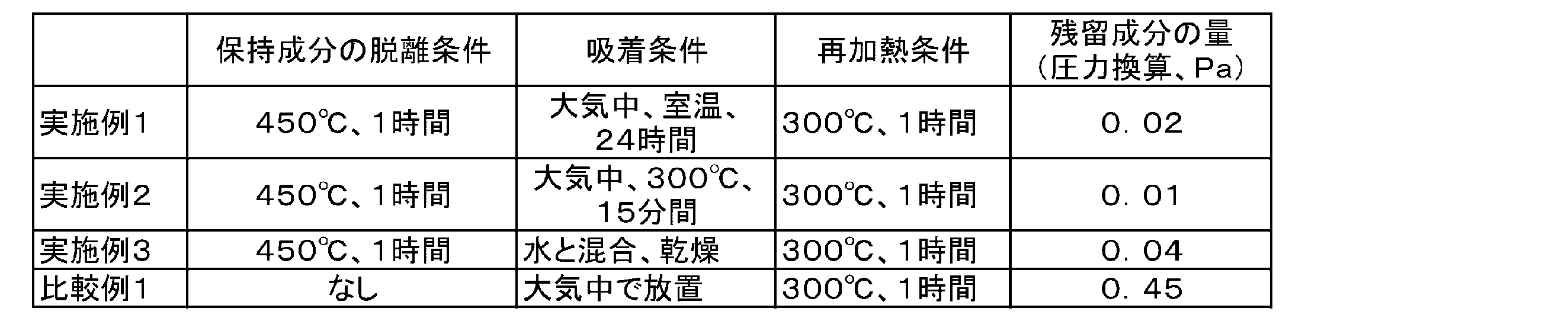
<銅イオン交換ゼオライトの評価>
未加熱の銅イオン交換ゼオライトを昇温させながら、各保持成分を脱離させた。このとき、昇温脱離ガス質量分析により、銅イオン交換ゼオライトの温度と、離脱した各保持成分の強度(Intensity)との関係を検出した。その結果を、図9A~図9Dに示す。図9A~図9Dでは、それぞれ、脱離された保持成分のうち、酸素、水、窒素、及び二酸化炭素の結果を示す。この結果より、水、窒素、及び二酸化炭素は、100℃近傍に脱離のピークが見られるが、酸素は、400℃近傍に脱離のピークが見られ、酸素は高温処理しないと脱離しにくいことがわかる。
未加熱の銅イオン交換ゼオライトを昇温させながら、各保持成分を脱離させた。このとき、昇温脱離ガス質量分析により、銅イオン交換ゼオライトの温度と、離脱した各保持成分の強度(Intensity)との関係を検出した。その結果を、図9A~図9Dに示す。図9A~図9Dでは、それぞれ、脱離された保持成分のうち、酸素、水、窒素、及び二酸化炭素の結果を示す。この結果より、水、窒素、及び二酸化炭素は、100℃近傍に脱離のピークが見られるが、酸素は、400℃近傍に脱離のピークが見られ、酸素は高温処理しないと脱離しにくいことがわかる。
<<製造例1~2、参考製造例1~2>>
下記に示す各部材を用いてガラスパネルユニットの、製造例1~2及び参考製造例1~2を行った。
・第1ガラス板(ガラス板のサイズ;幅×長さ×厚さ=300mm×300mm×3mm、Low-Eガラス放射率=0.04)、
・第2ガラス板(ガラス板のサイズ;幅×長さ×厚さ=300mm×300mm×3mm)、
・スペーサ(サイズ;直径×高さ=0.5mm×0.1mm、樹脂製)、
・溶媒;水、
・熱溶融シール材A;バナジウム系ガラスフリット、
・熱溶融シール材B;ビスマス系ガラスフリット。
下記に示す各部材を用いてガラスパネルユニットの、製造例1~2及び参考製造例1~2を行った。
・第1ガラス板(ガラス板のサイズ;幅×長さ×厚さ=300mm×300mm×3mm、Low-Eガラス放射率=0.04)、
・第2ガラス板(ガラス板のサイズ;幅×長さ×厚さ=300mm×300mm×3mm)、
・スペーサ(サイズ;直径×高さ=0.5mm×0.1mm、樹脂製)、
・溶媒;水、
・熱溶融シール材A;バナジウム系ガラスフリット、
・熱溶融シール材B;ビスマス系ガラスフリット。
[製造例1]
チャンバ内に銅イオン交換ゼオライト(未加熱)を配置させた。ゼオライトの配置後、チャンバ内を排気させて真空空間にさせながら、銅イオン交換ゼオライトを500℃で4時間加熱した。これにより、銅イオン交換ゼオライトに保持されていた保持成分を脱離させた。加熱後、チャンバ内を室温まで冷却させた。冷却後、銅イオン交換ゼオライトに対して吸着成分となる窒素ガスをチャンバ内に流し込んで、チャンバ内の気圧を大気圧にした。これによりゲッタ材を作製した。
チャンバ内に銅イオン交換ゼオライト(未加熱)を配置させた。ゼオライトの配置後、チャンバ内を排気させて真空空間にさせながら、銅イオン交換ゼオライトを500℃で4時間加熱した。これにより、銅イオン交換ゼオライトに保持されていた保持成分を脱離させた。加熱後、チャンバ内を室温まで冷却させた。冷却後、銅イオン交換ゼオライトに対して吸着成分となる窒素ガスをチャンバ内に流し込んで、チャンバ内の気圧を大気圧にした。これによりゲッタ材を作製した。
次に、ゲッタ材を水と混合してゲッタ材含有組成物を作製した。
その後、排気口を有する第2ガラス板の一面に、熱溶融シール材Aからなる枠体と、熱溶融シール材Aからなる仕切りと、通気路と、ガス吸着体と、複数のスペーサとを設けてから、第2ガラス板と対向するようにして第1ガラス板を配置させた。これにより、第1ガラス板と第2ガラス板との間に内部空間が形成された仮組み立て品が得られた。ガス吸着体を設ける際、ゲッタ材の使用量が0.1gとなるようにしてゲッタ材含有組成物を第2ガラス板に塗布した。また、スペーサを設ける際、隣り合うスペーサ同士の間隔が20mmとなるようにして複数のスペーサをディスペンサにより第2ガラス板に配置した。
続いて、真空ポンプと排気口とを排気管及びシールヘッドにより接続してから、仮組み立て品を溶融炉内に配置した。この配置後、仮組み立て品を280℃(第1溶融温度)で15分間加熱することで、枠体のガラスフリットを一旦溶融させた。この溶融時に通気路は塞がれていなかった。
枠体の溶融後、溶融炉内の温度を排気温度である250℃まで降温させた。そして、真空ポンプを作動させることにより、内部空間を250℃で120分間排気させた。
その後、真空ポンプを作動させたまま、溶融炉内の温度を第2溶融温度である290℃まで昇温させ、この温度で15分間仮組み立て品を加熱した。この加熱により仕切りを変形させて通気路を塞ぐ隔壁を形成した。
隔壁の形成後、溶融炉内の温度を室温まで降温させた。この降温後、真空ポンプを停止してシールヘッドを脱着させた。シールヘッドの脱着後、切断により不要な部分を取り除くことで、ガラスパネルユニットを作製した。
[製造例2]
ガス吸着体を設ける際にゲッタ材の使用量が0.5gとなるようにしてゲッタ材含有組成物を第2ガラス板に塗布した以外は、製造例1と同様にしてガラスパネルユニットを作製した。
ガス吸着体を設ける際にゲッタ材の使用量が0.5gとなるようにしてゲッタ材含有組成物を第2ガラス板に塗布した以外は、製造例1と同様にしてガラスパネルユニットを作製した。
[参考製造例1]
まず、未加熱の銅イオン交換ゼオライトを溶媒と混合してゲッタ材含有組成物を作製した。
まず、未加熱の銅イオン交換ゼオライトを溶媒と混合してゲッタ材含有組成物を作製した。
その後、排気口を有する第2ガラス板の一面に、熱溶融シール材Bからなる枠体と、熱溶融シール材Bからなる仕切りと、通気路と、ガス吸着体と、複数のスペーサとを設けてから、第2ガラス板と対向するようにして第1ガラス板を配置させた。これにより、第1ガラス板と第2ガラス板との間に内部空間が形成された仮組み立て品が得られた。ガス吸着体を設ける際、ゲッタ材の使用量が0.1gとなるようにしてゲッタ材含有組成物を第2ガラス板に塗布した。また、スペーサを設ける際、隣り合うスペーサ同士の間隔が20mmとなるようにして複数のスペーサをディスペンサにより第2ガラス板に配置した。
続いて、真空ポンプと排気口とを排気管及びシールヘッドにより接続してから、仮組み立て品を溶融炉内に配置した。この配置後、仮組み立て品を450℃(第1溶融温度)で10分間加熱することで、枠体のガラスフリットを一旦溶融させた。この溶融時に通気路は塞がれていなかった。
枠体の溶融後、溶融炉内の温度を排気温度である400℃まで降温させた。そして、真空ポンプを作動させることにより、内部空間を400℃で120分間排気させた。
その後、真空ポンプを作動させたまま、溶融炉内の温度を第2溶融温度である460℃まで昇温させ、この温度で30分間仮組み立て品を加熱した。この加熱により仕切りを変形させて通気路を塞ぐ隔壁を形成した。
隔壁の形成後、溶融炉内の温度を室温まで降温させた。この降温後、真空ポンプを停止してシールヘッドを脱着させた。シールヘッドの脱着後、切断により不要な部分を取り除くことで、ガラスパネルユニットを作製した。
[参考製造例2]
枠体と、仕切りを設ける際に熱溶融シール材Aを用い、第1溶融温度を280℃にし、排気温度を250℃にし、第2溶融温度を290℃にした以外は、参考製造例1と同様にしてガラスパネルユニットを作製した。
枠体と、仕切りを設ける際に熱溶融シール材Aを用い、第1溶融温度を280℃にし、排気温度を250℃にし、第2溶融温度を290℃にした以外は、参考製造例1と同様にしてガラスパネルユニットを作製した。
(評価)
[熱コンダクタンス]
各製造例及び参考製造例のガラスパネルユニットの熱コンダクタンスを下記の手順で評価した。測定装置の高温部と低温部とがガラスパネルユニットにより仕切られた状態にし、第1ガラス板の外面に第1温度計を配置し、第2ガラス板の外面に第2温度計と、センサとを配置した。この配置後、ガラスパネルユニットを介して加温部から冷却部に伝えられた熱の流束をセンサで検出し、第1温度計で第1ガラス板の表面温度を測定し、第2温度計で第2ガラス板2の表面温度が測定した。
[熱コンダクタンス]
各製造例及び参考製造例のガラスパネルユニットの熱コンダクタンスを下記の手順で評価した。測定装置の高温部と低温部とがガラスパネルユニットにより仕切られた状態にし、第1ガラス板の外面に第1温度計を配置し、第2ガラス板の外面に第2温度計と、センサとを配置した。この配置後、ガラスパネルユニットを介して加温部から冷却部に伝えられた熱の流束をセンサで検出し、第1温度計で第1ガラス板の表面温度を測定し、第2温度計で第2ガラス板2の表面温度が測定した。
そして、熱流束と、第1ガラス板の表面温度と、第2ガラス板の表面温度と、を下記式(1)に導入することで、ガラスパネルユニットの熱コンダクタンスを算出した。
Q=C(T1-T2) ・・・(1)
式(1)中、Qは熱流束(W/m2)を示し、T1は第1ガラス板の表面温度(K)を示し、T2は第2ガラス板の表面温度(K)を示し、Cは熱コンダクタンス(W/m2K)を示す。
式(1)中、Qは熱流束(W/m2)を示し、T1は第1ガラス板の表面温度(K)を示し、T2は第2ガラス板の表面温度(K)を示し、Cは熱コンダクタンス(W/m2K)を示す。
製造例1の熱コンダクタンスは5.0W/m2Kであり、製造例2の熱コンダクタンスは0.8W/m2Kであり、参考製造例1の熱コンダクタンスは0.8W/m2Kであり、参考製造例2の熱コンダクタンスは31W/m2Kであった。
上記の結果から、製造例1、2では第1及び第2溶融温度が比較的低い温度であるものの、熱コンダクタンスが低下しやすい傾向が得られた。また、参考製造例1でも熱コンダクタンスが低下しやすい傾向が得られたが、これは第1及び第2溶融温度が450℃以上であるため、排気工程でこの温度により未加熱の銅イオン交換ゼオライトが保持していた保持成分が気化して排気されたためと考えられる。参考製造例1の結果から、未加熱のゲッタ材を用いると、仮組み立て品の加熱温度は保持成分が気化する温度まで高くなり、この加熱温度により仮組み立て品内の部品が破損してしまうことが予想される。また、参考製造例2では熱コンダクタンスが低下しにくい傾向が得られた。参考製造例2の結果から、熱コンダクタンスを低下させるには、未加熱のゲッタ材の使用量が多くなりやすい。
(まとめ)
上記説明の通り、第1態様は、ガラスパネルユニット(10)の製造方法であって、未処理のゲッタ材(1a)を所定温度(Te)よりも高い温度で加熱して、ゲッタ材(1)を作製する工程と、仮組み立て品(100)を作製する工程とを含む。仮組み立て品(100)は、第1ガラス板(200)と、第2ガラス板(300)と、枠状の熱溶融シール材(410)と、内部空間(500)と、ガス吸着体(60)と、排気口(700)とを備える。第2ガラス板(300)は、第1ガラス板(200)に対向するように配置されている。枠状の熱溶融シール材(410)は、第1ガラス板(200)と第2ガラス板(300)との間に配置されて第1ガラス板(200)と第2ガラス板(300)とに接触している。ガス吸着体(60)は、ゲッタ材(1)を含有し、内部空間(500)内に配置されている。排気口(700)は、内部空間(500)と外部空間とをつなぐ。第1態様の製造方法は、加熱により枠状の熱溶融シール材(410)を溶融させることで第1ガラス板(200)と第2ガラス板(300)とに気密に接合する枠体(411)を形成する工程を更に含む。第1態様の製造方法は、排気口(700)を介して排気することで内部空間(500)を減圧させながら、所定温度(Te)でガス吸着体(60)を加熱する工程をまた更に含む。
上記説明の通り、第1態様は、ガラスパネルユニット(10)の製造方法であって、未処理のゲッタ材(1a)を所定温度(Te)よりも高い温度で加熱して、ゲッタ材(1)を作製する工程と、仮組み立て品(100)を作製する工程とを含む。仮組み立て品(100)は、第1ガラス板(200)と、第2ガラス板(300)と、枠状の熱溶融シール材(410)と、内部空間(500)と、ガス吸着体(60)と、排気口(700)とを備える。第2ガラス板(300)は、第1ガラス板(200)に対向するように配置されている。枠状の熱溶融シール材(410)は、第1ガラス板(200)と第2ガラス板(300)との間に配置されて第1ガラス板(200)と第2ガラス板(300)とに接触している。ガス吸着体(60)は、ゲッタ材(1)を含有し、内部空間(500)内に配置されている。排気口(700)は、内部空間(500)と外部空間とをつなぐ。第1態様の製造方法は、加熱により枠状の熱溶融シール材(410)を溶融させることで第1ガラス板(200)と第2ガラス板(300)とに気密に接合する枠体(411)を形成する工程を更に含む。第1態様の製造方法は、排気口(700)を介して排気することで内部空間(500)を減圧させながら、所定温度(Te)でガス吸着体(60)を加熱する工程をまた更に含む。
第1態様によれば、ガス吸着体(60)がゲッタ材(1)を含有することで、ゲッタ材(1)の使用量を軽減でき、ゲッタ材(1)周辺の部品を破損させにくくする比較的低い温度でゲッタリング能力を実現できる。
第2態様は、第1態様のガラスパネルユニット(10)の製造方法であって、仮組み立て品(100)は、仕切り(420)と、通気路(600)とを更に備える。仕切り(420)は、内部空間(500)を、第1空間(510)と、排気口(700)がある第2空間(520)とに仕切る。通気路(600)は、第1空間(510)と第2空間(520)とをつなぐ。第2態様の製造方法は、所定温度(Te)よりも高い温度で仕切り(420)を変形させて通気路(600)を塞ぐ隔壁(42)を形成することにより、隔壁(42)で第1空間(510)と第2空間(520)とを区分する工程を更に含む。この工程では、ガス吸着体(60)の加熱後、排気口(700)を介して排気することで内部空間(500)を減圧させる。
第2態様によれば、所定温度(Te)よりも高い温度で仕切り(420)を変形させても、第1空間(510)に対応する部分の真空空間(50)において、真空度の悪化を抑制することができる。すなわち、真空空間(50)中のゲッタ材(1)の使用量を軽減でき、ゲッタ材(1)周辺の部品を破損させにくくする比較的低い温度でゲッタリング能力を実現できる。
第3態様は、第1又は第2態様のガラスパネルユニット(10)の製造方法であって、未処理のゲッタ材(1a)を、ネオン、キセノン、及びアルゴンからなる群から選択される少なくとも1種を含む不活性ガスの雰囲気下または減圧下で加熱する。
第3態様によれば、ゲッタ材(1)の使用量を軽減でき、ゲッタ材(1)周辺の部品を破損させにくくする比較的低い温度でゲッタリング能力を実現できる。
第4態様は、ゲッタ材(1)の製造方法であって、未処理のゲッタ材(1a)に保持されている保持成分(5)を加熱下で気化及び脱離させて、未処理のゲッタ材(1a)の本体(2)を固形の残部として生成することを含む。前記製造方法は、保持成分(5)の脱離後、本体(2)との結合エネルギーが、温度換算で、所定温度以下になる吸着成分(3)を本体(2)に吸着させることで、ゲッタ材(1)を作製することとを更に含む。ゲッタ材(1)は、吸着成分(3)を温度換算で前記結合エネルギー以上の温度で気化及び脱離させることにより、吸着成分(3)とは別のガス成分を少なくとも吸着可能である。
第4態様によれば、ゲッタ材(1)の使用量を軽減でき、ゲッタ材(1)周辺の部品を破損させにくくする比較的低い温度でゲッタリング能力を実現するゲッタ材(1)を得ることができる。
第5態様は、第4態様の変形例であるゲッタ材(1)の製造方法であって、未処理のゲッタ材(1a)に保持されている保持成分(5)を不活性ガスの雰囲気下または減圧下で加熱し気化及び脱離させて、未処理のゲッタ材(1a)の本体(2)を固形の残部として生成することを含む。前記製造方法は、保持成分(5)の脱離後、本体(2)との結合エネルギーが、温度換算で、所定温度以下になる吸着成分(3)を本体(2)に吸着させることで、ゲッタ材(1)を作製することとを更に含む。ゲッタ材(1)は、吸着成分(3)を温度換算で前記結合エネルギー以上の温度で気化及び脱離させることにより、吸着成分(3)とは別のガス成分を少なくとも吸着可能である。
第5態様によれば、ゲッタ材(1)の使用量を軽減でき、ゲッタ材(1)周辺の部品を破損させにくくする比較的低い温度でゲッタリング能力を実現するゲッタ材(1)を得ることができる。
第6態様は、第4態様または第5様態のゲッタ材(1)の製造方法であって、吸着成分(3)は、窒素、水素、二酸化炭素、水、ネオン、キセノン、炭化水素、及び炭化水素誘導体からなる群から選択される少なくとも1種の成分を含む。
第6態様によれば、ゲッタ材(1)の使用量を軽減でき、ゲッタ材(1)周辺の部品を破損させにくくする比較的低い温度でゲッタリング能力を実現するゲッタ材(1)を得ることができる。
第7態様は、第4~第6形態のいずれか1つのゲッタ材(1)の製造方法であって、本体(2)は、ゼオライト、又は銅イオン交換ゼオライトである。
第7態様によれば、ゲッタ材(1)の使用量を軽減でき、ゲッタ材(1)周辺の部品を破損させにくくする比較的低い温度でゲッタリング能力を実現するゲッタ材(1)を得ることができる。
第8態様は、ゲッタ材含有組成物(1b)の製造方法であって、ゲッタ材を溶媒と混合することを含む。ゲッタ材は、第4~第7態様のいずれか1つのゲッタ材の製造方法で作製されたゲッタ材(1)である。
第8態様によれば、ゲッタ材(1)の使用量を軽減でき、ゲッタ材(1)周辺の部品を破損させにくくする比較的低い温度でゲッタリング能力を実現するゲッタ材含有組成物(1b)を得ることができる。
第9態様は、ゲッタ材(1)であって、吸着成分(3)と、本体(2)とを含む。本体(2)では吸着成分(3)が吸着されている。吸着成分(3)は、温度換算で所定温度以下の結合エネルギーで本体(2)に吸着されている。ゲッタ材(1)は、吸着成分(3)を温度換算で前記結合エネルギー以上の温度で気化及び脱離させることにより、吸着成分(3)とは別のガス成分を少なくとも吸着可能である。
第9態様によれば、ゲッタ材(1)の使用量を軽減でき、ゲッタ材(1)周辺の部品を破損させにくくする比較的低い温度でゲッタリング能力を実現できる。
第10態様は、第9態様のゲッタ材(1)であって、第2吸着成分(4)を更に含む。吸着成分(3)は、第1吸着成分である。第2吸着成分(4)は、温度換算で所定温度よりも高い温度の結合エネルギーで本体(2)に吸着されている。ゲッタ材(1)は、第1吸着成分(3)を、第2吸着成分(4)よりも多い含有量で含む。
第10態様によれば、第2吸着成分(4)は微量成分として本体(2)に吸着されているため、ゲッタ材(1)の使用量を軽減でき、ゲッタ材(1)周辺の部品を破損させにくくする比較的低い温度でゲッタリング能力を実現できる。
第11態様は、第9又は第10態様のゲッタ材(1)であって、本体(2)は、未処理のゲッタ材(1a)に保持された保持成分(5)を気化及び脱離させた固形の残部である。
第11態様によれば、ゲッタ材(1)の使用量を軽減でき、ゲッタ材(1)周辺の部品を破損させにくくする比較的低い温度でゲッタリング能力を実現できる。
第12態様は、第9~第11態様のいずれか1つのゲッタ材(1)であって、吸着成分(3)は、窒素、水素、二酸化炭素、水、ネオン、キセノン、炭化水素、及び炭化水素誘導体からなる群から選択される少なくとも1種の成分を含む。
第12態様によれば、ゲッタ材(1)の使用量を軽減でき、ゲッタ材(1)周辺の部品を破損させにくくする比較的低い温度でゲッタリング能力を実現できる。
第13態様は、第9~第12態様のいずれか1つのゲッタ材(1)であって、本体(2)は、ゼオライト、又は銅イオン交換ゼオライトである。
第13態様によれば、ゲッタ材(1)の使用量を軽減でき、ゲッタ材(1)周辺の部品を破損させにくくする比較的低い温度でゲッタリング能力を実現できる。
第14態様は、ゲッタ材含有組成物(1b)の製造方法であって、ゲッタ材を溶媒と混合することを含む。ゲッタ材は、第9~第13態様のいずれか1つのゲッタ材の製造方法で作製されたゲッタ材(1)である。
第14態様によれば、ゲッタ材(1)の使用量を軽減でき、ゲッタ材(1)周辺の部品を破損させにくくする比較的低い温度でゲッタリング能力を実現するゲッタ材含有組成物(1b)を得ることができる。
1 ゲッタ材
1a 未処理のゲッタ材
2 本体(ゲッタ材本体)
3 吸着成分
10 ガラスパネルユニット
100 仮組み立て品
200 第1ガラス板
300 第2ガラス板
410 枠状の熱溶融シール材
411 枠体
500 内部空間
60 ガス吸着体
700 排気口
Te 所定温度
1a 未処理のゲッタ材
2 本体(ゲッタ材本体)
3 吸着成分
10 ガラスパネルユニット
100 仮組み立て品
200 第1ガラス板
300 第2ガラス板
410 枠状の熱溶融シール材
411 枠体
500 内部空間
60 ガス吸着体
700 排気口
Te 所定温度
Claims (12)
- ガラスパネルユニットの製造方法であって、
未処理のゲッタ材を所定温度よりも高い温度で加熱して、ゲッタ材を作製する工程と、
第1ガラス板と、
前記第1ガラス板に対向するように配置された第2ガラス板と、
前記第1ガラス板と前記第2ガラス板との間に配置されて前記第1ガラス板と前記第2ガラス板とに接触している枠状の熱溶融シール材と、
前記第1ガラス板と前記第2ガラス板と前記枠状の熱溶融シール材とで囲まれた内部空間と、
前記ゲッタ材を含有し、前記内部空間内に配置されたガス吸着体と、
前記内部空間と外部空間とをつなぐ排気口と、
を備える仮組み立て品を作製する工程と、
加熱により前記枠状の熱溶融シール材を溶融させることで前記第1ガラス板と前記第2ガラス板とに気密に接合する枠体を形成する工程と、
前記排気口を介して排気することで前記内部空間を減圧させながら、前記所定温度で前記ガス吸着体を加熱する工程と、
を含む、
ガラスパネルユニットの製造方法。 - 前記仮組み立て品は、前記内部空間を第1空間と、前記排気口がある第2空間とに仕切る仕切りと、前記第1空間と前記第2空間とをつなぐ通気路を更に備え、
前記ガス吸着体の加熱後、前記排気口を介して排気することで前記内部空間を減圧させながら、前記所定温度よりも高い温度で前記仕切りを変形させて前記通気路を塞ぐ隔壁を形成することにより、前記隔壁で前記第1空間と前記第2空間とを区分する工程を更に含む、
請求項1に記載のガラスパネルユニットの製造方法。 - 前記未処理のゲッタ材を、ネオン、キセノン、及びアルゴンからなる群から選択される少なくとも1種を含む不活性ガスの雰囲気下または減圧下で加熱する、
請求項1又は2に記載のガラスパネルユニットの製造方法。 - 未処理のゲッタ材に保持されている保持成分を加熱下で気化及び脱離させて、前記未処理のゲッタ材の本体を固形の残部として生成することと、
前記保持成分の脱離後、前記本体との結合エネルギーが、温度換算で、所定温度以下になる吸着成分を前記本体に吸着させることで、ゲッタ材を作製することと、
を含み、
前記ゲッタ材は、前記吸着成分を温度換算で前記結合エネルギー以上の温度で気化及び脱離させることにより、前記吸着成分とは別のガス成分を少なくとも吸着可能である、
ゲッタ材の製造方法。 - 前記吸着成分は、窒素、水素、二酸化炭素、水、ネオン、キセノン、炭化水素、及び炭化水素誘導体からなる群から選択される少なくとも1種の成分を含む、
請求項4に記載のゲッタ材の製造方法。 - 前記本体は、ゼオライト、又は銅イオン交換ゼオライトである、
請求項4又は5に記載のゲッタ材の製造方法。 - 請求項4~6のいずれか1項に記載のゲッタ材の製造方法で作製されたゲッタ材を溶媒と混合することを含む、
ゲッタ材含有組成物の製造方法。 - ゲッタ材であって、
吸着成分と、
前記吸着成分が吸着されている本体と、
を含み、
前記吸着成分は、温度換算で所定温度以下の結合エネルギーで前記本体に吸着されており、
前記ゲッタ材は、前記吸着成分を温度換算で前記結合エネルギー以上の温度で気化及び脱離させることにより、前記吸着成分とは別のガス成分を少なくとも吸着可能である、
ゲッタ材。 - 前記吸着成分は、第1吸着成分であり、
温度換算で前記所定温度よりも高い温度の結合エネルギーで前記本体に吸着されている第2吸着成分を更に含み、
前記ゲッタ材は、前記第1吸着成分を、前記第2吸着成分よりも多い含有量で含む、
請求項8に記載のゲッタ材。 - 前記本体は、未処理のゲッタ材に保持された保持成分を気化及び脱離させた固形の残部である、
請求項8又は9に記載のゲッタ材。 - 前記吸着成分は、窒素、水素、二酸化炭素、水、ネオン、キセノン、炭化水素、及び炭化水素誘導体からなる群から選択される少なくとも1種の成分を含む、
請求項8~10のいずれか1項に記載のゲッタ材。 - 前記本体は、ゼオライト、又は銅イオン交換ゼオライトである、
請求項8~11のいずれか1項に記載のゲッタ材。
Priority Applications (4)
| Application Number | Priority Date | Filing Date | Title |
|---|---|---|---|
| US17/041,873 US20210009471A1 (en) | 2018-03-30 | 2019-03-15 | Getter material, method for manufacturing getter material, method for manufacturing getter-material-containing composition, and method for manufacturing glass panel unit |
| JP2020510656A JP7008229B2 (ja) | 2018-03-30 | 2019-03-15 | ガラスパネルユニットの製造方法 |
| EP19776341.0A EP3778006A4 (en) | 2018-03-30 | 2019-03-15 | GETTER MATERIAL, METHOD FOR MANUFACTURING A GETTER MATERIAL, METHOD FOR MANUFACTURING A GETTERAL COMPOSITION AND METHOD FOR MANUFACTURING A GLASS PANEL UNIT |
| JP2021175011A JP7325051B2 (ja) | 2018-03-30 | 2021-10-26 | ゲッタ材、ゲッタ材の製造方法、及びゲッタ材含有組成物の製造方法 |
Applications Claiming Priority (2)
| Application Number | Priority Date | Filing Date | Title |
|---|---|---|---|
| JP2018069724 | 2018-03-30 | ||
| JP2018-069724 | 2018-03-30 |
Publications (1)
| Publication Number | Publication Date |
|---|---|
| WO2019188424A1 true WO2019188424A1 (ja) | 2019-10-03 |
Family
ID=68058814
Family Applications (1)
| Application Number | Title | Priority Date | Filing Date |
|---|---|---|---|
| PCT/JP2019/010874 WO2019188424A1 (ja) | 2018-03-30 | 2019-03-15 | ゲッタ材、ゲッタ材の製造方法、ゲッタ材含有組成物の製造方法、及びガラスパネルユニットの製造方法 |
Country Status (4)
| Country | Link |
|---|---|
| US (1) | US20210009471A1 (ja) |
| EP (1) | EP3778006A4 (ja) |
| JP (2) | JP7008229B2 (ja) |
| WO (1) | WO2019188424A1 (ja) |
Cited By (2)
| Publication number | Priority date | Publication date | Assignee | Title |
|---|---|---|---|---|
| WO2020255974A1 (ja) * | 2019-06-17 | 2020-12-24 | パナソニックIpマネジメント株式会社 | ガラスパネルユニット、ガラスパネルユニットの製造方法、複合ゲッタ材、及びゲッタペースト |
| WO2021225083A1 (ja) * | 2020-05-08 | 2021-11-11 | パナソニックIpマネジメント株式会社 | ガラスパネルユニット、ゲッタ材、ゲッタ材組成物、ガラスパネルユニットの製造方法 |
Families Citing this family (1)
| Publication number | Priority date | Publication date | Assignee | Title |
|---|---|---|---|---|
| KR101719911B1 (ko) * | 2015-07-22 | 2017-03-24 | 한국항공우주연구원 | 설정 기압을 제공하는 저압 챔버 |
Citations (4)
| Publication number | Priority date | Publication date | Assignee | Title |
|---|---|---|---|---|
| JP2007511102A (ja) | 2003-11-12 | 2007-04-26 | イー・アイ・デュポン・ドウ・ヌムール・アンド・カンパニー | 電子デバイス中に使用される表面にゲッター材料を接着する方法 |
| JP2016069232A (ja) * | 2014-09-30 | 2016-05-09 | パナソニックIpマネジメント株式会社 | ガラスパネルユニット、ガラスパネルユニットの組立て品、ガラスパネルユニットの製造方法 |
| WO2018043376A1 (ja) * | 2016-08-31 | 2018-03-08 | パナソニックIpマネジメント株式会社 | ガラスパネルユニットおよびガラス窓 |
| WO2019004135A1 (ja) * | 2017-06-30 | 2019-01-03 | パナソニックIpマネジメント株式会社 | ガラスパネルユニットの製造方法 |
Family Cites Families (2)
| Publication number | Priority date | Publication date | Assignee | Title |
|---|---|---|---|---|
| US5314853A (en) * | 1992-12-16 | 1994-05-24 | The United States Of America As Represented By The Administrator Of The National Aeronautics And Space Administration | High temperature sorbents for oxygen |
| JP5392745B2 (ja) * | 2008-08-18 | 2014-01-22 | 大陽日酸株式会社 | キセノンの濃縮方法、キセノン濃縮装置、及び空気液化分離装置 |
-
2019
- 2019-03-15 JP JP2020510656A patent/JP7008229B2/ja active Active
- 2019-03-15 WO PCT/JP2019/010874 patent/WO2019188424A1/ja active Application Filing
- 2019-03-15 EP EP19776341.0A patent/EP3778006A4/en active Pending
- 2019-03-15 US US17/041,873 patent/US20210009471A1/en active Pending
-
2021
- 2021-10-26 JP JP2021175011A patent/JP7325051B2/ja active Active
Patent Citations (4)
| Publication number | Priority date | Publication date | Assignee | Title |
|---|---|---|---|---|
| JP2007511102A (ja) | 2003-11-12 | 2007-04-26 | イー・アイ・デュポン・ドウ・ヌムール・アンド・カンパニー | 電子デバイス中に使用される表面にゲッター材料を接着する方法 |
| JP2016069232A (ja) * | 2014-09-30 | 2016-05-09 | パナソニックIpマネジメント株式会社 | ガラスパネルユニット、ガラスパネルユニットの組立て品、ガラスパネルユニットの製造方法 |
| WO2018043376A1 (ja) * | 2016-08-31 | 2018-03-08 | パナソニックIpマネジメント株式会社 | ガラスパネルユニットおよびガラス窓 |
| WO2019004135A1 (ja) * | 2017-06-30 | 2019-01-03 | パナソニックIpマネジメント株式会社 | ガラスパネルユニットの製造方法 |
Cited By (7)
| Publication number | Priority date | Publication date | Assignee | Title |
|---|---|---|---|---|
| WO2020255974A1 (ja) * | 2019-06-17 | 2020-12-24 | パナソニックIpマネジメント株式会社 | ガラスパネルユニット、ガラスパネルユニットの製造方法、複合ゲッタ材、及びゲッタペースト |
| JPWO2020255974A1 (ja) * | 2019-06-17 | 2020-12-24 | ||
| JP7266254B2 (ja) | 2019-06-17 | 2023-04-28 | パナソニックIpマネジメント株式会社 | ガラスパネルユニット、ガラスパネルユニットの製造方法 |
| JP7466130B2 (ja) | 2019-06-17 | 2024-04-12 | パナソニックIpマネジメント株式会社 | ガラスパネルユニット、ガラスパネルユニットの製造方法 |
| WO2021225083A1 (ja) * | 2020-05-08 | 2021-11-11 | パナソニックIpマネジメント株式会社 | ガラスパネルユニット、ゲッタ材、ゲッタ材組成物、ガラスパネルユニットの製造方法 |
| CN115485250A (zh) * | 2020-05-08 | 2022-12-16 | 松下知识产权经营株式会社 | 玻璃面板单元、吸气材料、吸气材料组合物以及用于制造玻璃面板单元的方法 |
| JP7462241B2 (ja) | 2020-05-08 | 2024-04-05 | パナソニックIpマネジメント株式会社 | ガラスパネルユニット、ゲッタ材 |
Also Published As
| Publication number | Publication date |
|---|---|
| EP3778006A1 (en) | 2021-02-17 |
| JP7008229B2 (ja) | 2022-01-25 |
| EP3778006A4 (en) | 2021-09-01 |
| JPWO2019188424A1 (ja) | 2021-03-25 |
| JP2022009520A (ja) | 2022-01-14 |
| JP7325051B2 (ja) | 2023-08-14 |
| US20210009471A1 (en) | 2021-01-14 |
Similar Documents
| Publication | Publication Date | Title |
|---|---|---|
| JP7325051B2 (ja) | ゲッタ材、ゲッタ材の製造方法、及びゲッタ材含有組成物の製造方法 | |
| CN105008302A (zh) | 多层玻璃和多层玻璃的制备方法 | |
| KR101360474B1 (ko) | 복합 게터제를 포함하는 진공 단열재 | |
| EP3202727B1 (en) | Glass panel unit and inspection method thereof | |
| US10378272B2 (en) | Glass panel unit, temporary assembly of glass panel unit, completed assembly of glass panel unit, method for manufacturing glass panel unit | |
| JP7266254B2 (ja) | ガラスパネルユニット、ガラスパネルユニットの製造方法 | |
| TWI666375B (zh) | 玻璃平板單元及玻璃窗 | |
| US20190084877A1 (en) | Manufacturing method of glass panel unit | |
| JP6528335B2 (ja) | ガラスパネルユニット | |
| US20170210667A1 (en) | Method for manufacturing glass panel unit | |
| CN107073441B (zh) | 气体吸附体、气体吸附体的制备方法、玻璃面板单元 | |
| US11767706B2 (en) | Method for manufacturing glass panel unit, and method for manufacturing glass window | |
| US11162297B2 (en) | Glass panel unit assembly, and method for manufacturing glass panel unit | |
| US11230878B2 (en) | Glass panel unit assembly and method for manufacturing glass panel unit | |
| US11428041B2 (en) | Glass panel unit assembly, method for manufacturing glass panel unit, work in progress of glass panel unit, and glass panel unit | |
| US11148971B2 (en) | Method for manufacturing glass panel unit, method for manufacturing building component, and gas adsorption unit | |
| WO2021225083A1 (ja) | ガラスパネルユニット、ゲッタ材、ゲッタ材組成物、ガラスパネルユニットの製造方法 | |
| WO2020017221A1 (ja) | ガラスパネルユニット、及びガラスパネルユニットの製造方法 | |
| JP2023119361A (ja) | 複層ガラスパネル |
Legal Events
| Date | Code | Title | Description |
|---|---|---|---|
| 121 | Ep: the epo has been informed by wipo that ep was designated in this application |
Ref document number: 19776341 Country of ref document: EP Kind code of ref document: A1 |
|
| ENP | Entry into the national phase |
Ref document number: 2020510656 Country of ref document: JP Kind code of ref document: A |
|
| WWE | Wipo information: entry into national phase |
Ref document number: 2019776341 Country of ref document: EP |