WO2019187350A1 - 不正検知方法、不正検知装置及びプログラム - Google Patents
不正検知方法、不正検知装置及びプログラム Download PDFInfo
- Publication number
- WO2019187350A1 WO2019187350A1 PCT/JP2018/044568 JP2018044568W WO2019187350A1 WO 2019187350 A1 WO2019187350 A1 WO 2019187350A1 JP 2018044568 W JP2018044568 W JP 2018044568W WO 2019187350 A1 WO2019187350 A1 WO 2019187350A1
- Authority
- WO
- WIPO (PCT)
- Prior art keywords
- message
- unit
- arbitration
- period
- fraud detection
- Prior art date
- Legal status (The legal status is an assumption and is not a legal conclusion. Google has not performed a legal analysis and makes no representation as to the accuracy of the status listed.)
- Ceased
Links
Images


Classifications
-
- H—ELECTRICITY
- H04—ELECTRIC COMMUNICATION TECHNIQUE
- H04L—TRANSMISSION OF DIGITAL INFORMATION, e.g. TELEGRAPHIC COMMUNICATION
- H04L12/00—Data switching networks
- H04L12/28—Data switching networks characterised by path configuration, e.g. LAN [Local Area Networks] or WAN [Wide Area Networks]
- H04L12/40—Bus networks
- H04L12/40006—Architecture of a communication node
- H04L12/40013—Details regarding a bus controller
-
- H—ELECTRICITY
- H04—ELECTRIC COMMUNICATION TECHNIQUE
- H04L—TRANSMISSION OF DIGITAL INFORMATION, e.g. TELEGRAPHIC COMMUNICATION
- H04L63/00—Network architectures or network communication protocols for network security
- H04L63/14—Network architectures or network communication protocols for network security for detecting or protecting against malicious traffic
- H04L63/1408—Network architectures or network communication protocols for network security for detecting or protecting against malicious traffic by monitoring network traffic
- H04L63/1425—Traffic logging, e.g. anomaly detection
-
- H—ELECTRICITY
- H04—ELECTRIC COMMUNICATION TECHNIQUE
- H04L—TRANSMISSION OF DIGITAL INFORMATION, e.g. TELEGRAPHIC COMMUNICATION
- H04L12/00—Data switching networks
- H04L12/28—Data switching networks characterised by path configuration, e.g. LAN [Local Area Networks] or WAN [Wide Area Networks]
- H04L12/40—Bus networks
- H04L12/40006—Architecture of a communication node
- H04L12/40026—Details regarding a bus guardian
-
- H—ELECTRICITY
- H04—ELECTRIC COMMUNICATION TECHNIQUE
- H04L—TRANSMISSION OF DIGITAL INFORMATION, e.g. TELEGRAPHIC COMMUNICATION
- H04L12/00—Data switching networks
- H04L12/28—Data switching networks characterised by path configuration, e.g. LAN [Local Area Networks] or WAN [Wide Area Networks]
- H04L12/40—Bus networks
- H04L12/407—Bus networks with decentralised control
- H04L12/413—Bus networks with decentralised control with random access, e.g. carrier-sense multiple-access with collision detection [CSMA-CD]
- H04L12/4135—Bus networks with decentralised control with random access, e.g. carrier-sense multiple-access with collision detection [CSMA-CD] using bit-wise arbitration
-
- H—ELECTRICITY
- H04—ELECTRIC COMMUNICATION TECHNIQUE
- H04L—TRANSMISSION OF DIGITAL INFORMATION, e.g. TELEGRAPHIC COMMUNICATION
- H04L63/00—Network architectures or network communication protocols for network security
- H04L63/14—Network architectures or network communication protocols for network security for detecting or protecting against malicious traffic
- H04L63/1441—Countermeasures against malicious traffic
- H04L63/1466—Active attacks involving interception, injection, modification, spoofing of data unit addresses, e.g. hijacking, packet injection or TCP sequence number attacks
-
- H—ELECTRICITY
- H04—ELECTRIC COMMUNICATION TECHNIQUE
- H04L—TRANSMISSION OF DIGITAL INFORMATION, e.g. TELEGRAPHIC COMMUNICATION
- H04L67/00—Network arrangements or protocols for supporting network services or applications
- H04L67/01—Protocols
- H04L67/12—Protocols specially adapted for proprietary or special-purpose networking environments, e.g. medical networks, sensor networks, networks in vehicles or remote metering networks
-
- H—ELECTRICITY
- H04—ELECTRIC COMMUNICATION TECHNIQUE
- H04W—WIRELESS COMMUNICATION NETWORKS
- H04W4/00—Services specially adapted for wireless communication networks; Facilities therefor
- H04W4/30—Services specially adapted for particular environments, situations or purposes
- H04W4/40—Services specially adapted for particular environments, situations or purposes for vehicles, e.g. vehicle-to-pedestrians [V2P]
- H04W4/48—Services specially adapted for particular environments, situations or purposes for vehicles, e.g. vehicle-to-pedestrians [V2P] for in-vehicle communication
-
- H—ELECTRICITY
- H04—ELECTRIC COMMUNICATION TECHNIQUE
- H04L—TRANSMISSION OF DIGITAL INFORMATION, e.g. TELEGRAPHIC COMMUNICATION
- H04L12/00—Data switching networks
- H04L12/28—Data switching networks characterised by path configuration, e.g. LAN [Local Area Networks] or WAN [Wide Area Networks]
- H04L12/40—Bus networks
- H04L2012/40208—Bus networks characterized by the use of a particular bus standard
- H04L2012/40215—Controller Area Network CAN
-
- H—ELECTRICITY
- H04—ELECTRIC COMMUNICATION TECHNIQUE
- H04L—TRANSMISSION OF DIGITAL INFORMATION, e.g. TELEGRAPHIC COMMUNICATION
- H04L12/00—Data switching networks
- H04L12/28—Data switching networks characterised by path configuration, e.g. LAN [Local Area Networks] or WAN [Wide Area Networks]
- H04L12/40—Bus networks
- H04L2012/40267—Bus for use in transportation systems
- H04L2012/40273—Bus for use in transportation systems the transportation system being a vehicle
Definitions
- ECUs electronice control units
- in-vehicle network A communication network connecting these ECUs.
- CAN Controller Area Network
- a communication path is composed of two cables, and an ECU connected to the bus is also called a node.
- Each node connected to the bus transmits and receives data in units called frames or messages.
- an identifier indicating a data transmission destination or transmission source is not used.
- Patent Document 1 has a problem that a correct determination cannot be made when a normal message transmission cycle becomes longer due to a disturbance in the transmission cycle on the CAN network bus.
- the present disclosure solves the above-described problems, and an object thereof is to provide a fraud detection method, a fraud detection device, and the like that determine whether each message sent to the bus is an abnormal message.
- the fraud detection method or the like it is possible to determine whether or not an individual message sent to the bus is an abnormal message.
- FIG. 14 is a diagram illustrating an example of a fraud detection processing function group in the modification.
- FIG. 15 is a diagram illustrating an example of a fraud detection processing function group in the modified example.
- FIG. 16 is a block diagram illustrating an example of an ECU according to a modification.
- FIG. 17 is a block diagram illustrating an example of an ECU according to a modification.
- FIG. 18 is a block diagram illustrating an example of an ECU according to a modification.
- the CAN network has a function called “arbitration”, and a message with a small ID is preferentially transmitted, and a message with a large ID waits for transmission. If this happens, there will be a difference in the transmission timing for transmitting the message, so the function for determining whether the message is normal or abnormal according to the message transmission interval will malfunction, and the normal message will be determined to be an abnormal message. A possibility arises.
- a fraud detection method for detecting an abnormal message in an in-vehicle network system, which is executed by an information processing system including a storage unit, and is repeatedly applied to the in-vehicle network system.
- a period abnormality determining step for determining whether or not the period of the transmitted message is abnormal; and an arbitration detecting step for detecting whether or not arbitration has occurred when the message is transmitted to the in-vehicle network system;
- a transmission type determination step for determining the transmission type of the message may be included, and in the periodic start point determination step, the reception time or scheduled reception time of the message may be determined according to the transmission type.
- the arbitration detection step when the message is included in one or more messages continuously received from other messages received at a time within a normal range of the period for receiving the message, It may be determined that arbitration has occurred.
- a fraud detection device that detects an abnormal message in an in-vehicle network system, includes one or more processors and a storage unit, and uses the storage unit.
- the one or more processors are configured to determine whether or not a cycle of a message sent to the in-vehicle network system is abnormal, and when the message is sent to the in-vehicle network system.
- An arbitration detection step for detecting whether or not arbitration has occurred; and when the message cycle is abnormal and arbitration has occurred when the message is sent to the in-vehicle network system, A cycle determination step for determining a message is performed.
- a program according to an aspect of the present disclosure is a program for causing the one or more processors to perform any one of the fraud detection methods in the fraud detection apparatus.
- FIG. 1 is a block diagram showing an overall configuration of an in-vehicle network system 10 according to the present embodiment.
- the in-vehicle network system 10 includes a CAN network, and includes an ECU 100a, an ECU 100b, an ECU 100c, and an ECU 100d, a bus 200a and a bus 200b, and a gateway 300.
- the ECU 100a, the ECU 100b, the ECU 100c, and the ECU 100d may be collectively referred to as the ECU 100.
- the ECU 100 may be described as the ECU 100 by referring to any one of the ECU 100a, the ECU 100b, the ECU 100c, and the ECU 100d.
- bus 200a and the bus 200b may be collectively referred to as the bus 200. Further, the bus 200 may be referred to as either the bus 200a or the bus 200b.
- the ECU 100a is connected to the engine 101, and the ECU 100b is connected to the brake 102.
- the ECU 100 c is connected to the door opening / closing sensor 103, and the ECU 100 d is connected to the window opening / closing sensor 104.
- each ECU 100 reads a message transmitted from another ECU 100 from the bus 200, and selectively receives the message according to an ID attached to the message. This selective reception will be described later.
- Gateway 300 connects bus 200a to which ECU 100a and ECU 100b are connected and bus 200b to which ECU 100c and ECU 100d are connected.
- the gateway 300 has a function of transferring a message received from one bus to the other bus.
- the gateway 300 is also a node on the CAN network.
- the in-vehicle network system 10 is an example for explaining a target to which an unauthorized communication detection system or the like that determines whether a message is an abnormal message can be applied. It is not limited.
- the present invention may be applied to various network systems using a LAN (Local Area Network) or a distributed database.
- FIG. 2 is a diagram showing a format of a CAN protocol message (data frame). Here, a message in a standard ID format in the CAN protocol is shown.
- the message includes: Start Of Frame (SOF), ID field, Remote Transmission Request (RTR), IDE (IDentifier Extension), reserved bit (r), data length code (DLC), data field, CRC (Cyclic Redundant Sequence) , A CRC delimiter (left DEL in the figure), an ACK (Acknowledgement) slot, an ACK delimiter (right DEL in the figure), and an EOF (End Of Frame).
- SOF Start Of Frame
- ID field ID field
- RTR Remote Transmission Request
- IDE IDentifier Extension
- r data length code
- DLC data field
- CRC Cyclic Redundant Sequence
- a CRC delimiter left DEL in the figure
- an ACK Acknowledgement
- ACK delimiter right DEL in the figure
- EOF End Of Frame
- SOF is a 1-bit dominant. Dominant means dominance.
- a dominant is in a state where a voltage is applied to two cables constituting a bus so as to transmit a value of “0”, or this “0” transmitted. Is the value of.
- a state in which a voltage is applied so as to transmit a value of “1” to the two cables constituting the bus, or the value of “1” transmitted is called recessive. Recessive is inferior.
- the value of “0” and a value of “1” are transmitted simultaneously from two nodes to the bus, the value of “0” is prioritized.
- the bus at idle is in a recessive state.
- Each ECU 100 starts transmitting a message by changing the state of the bus 200 from recessive to dominant, and the other ECUs 100 read this change and synchronize.
- a portion in which a line indicating dominant or recessive constituting a message is a solid line indicates that each value of dominant or recessive can be taken. Since the SOF is fixed in the dominant state, the dominant line is a solid line and the recessive line is a broken line.
- ID is an 11-bit value indicating the type of data included in the message.
- the CAN is designed so that a message having a smaller ID value has a higher priority in communication arbitration between messages that a plurality of nodes have started to transmit simultaneously.
- Each IDE is a 1-bit dominant.
- DLC is a 4-bit value indicating the length of the following data field.
- the data field is a value indicating the content of data to be transmitted, and can be adjusted in units of 8 bits with a maximum length of 64 bits.
- the specifications regarding the assignment of data to be sent to this part depend on the vehicle type or manufacturer.
- the CRC delimiter is a 1-bit recessive fixed delimiter that represents the end of the CRC sequence.
- the receiving node determines the presence or absence of an abnormality by comparing the result calculated from the values of the SOF, ID field, control field, and data field of the received message with the CRC sequence value.
- ACK slot is 1 bit long, and the transmitting node transmits recessive in this part.
- the receiving node transmits a dominant as an acknowledgment if it has successfully received the CRC sequence. Since dominant is given priority, if communication of one message is normally performed up to the CRC sequence, the bus 200 during transmission of the ACK slot is dominant.
- ACK delimiter is fixed to 1 bit recessive and is a delimiter indicating the end of ACK slot.
- EOF is fixed to 7 bits recessive, indicating the end of the message.
- FIG. 3 is a block diagram showing a configuration of gateway 300 included in in-vehicle network system 10 according to the present embodiment.
- the gateway 300 includes a frame transmission / reception unit 310, a frame interpretation unit 320, a reception ID determination unit 330, a reception ID list holding unit 340, a frame processing unit 350, a transfer rule holding unit 360, and fraud detection.
- a processing function group 370 and a frame generation unit 380 are provided.
- the gateway 300 includes, for example, a processing unit realized by a processor, a storage unit realized by a semiconductor memory, an input / output unit realized by an input / output port, and the like. Provided as a processing device.
- the configuration showing the above functions is realized by reading and executing a program held in the storage unit by the processing unit and recording predetermined data in the storage unit.
- these configurations may be realized by performing transmission / reception of data via the input / output unit instead of recording predetermined data in the storage unit.
- the structure which shows said function may be implement
- the frame transmission / reception unit 310 transmits / receives a message according to the CAN protocol to each of the buses 200a, 200b.
- the frame transmission / reception unit 310 reads the message sent to the bus 200 bit by bit, and transfers the read message to the frame interpretation unit 320.
- the frame transmission / reception unit 310 sends a message to the buses 200a and 200b one bit at a time in accordance with the bus information transmitted from the frame generation unit 380.
- the frame transmission / reception unit 310 transmits the message received from the bus 200a to the bus 200b, and transmits the message received from the bus 200b to the bus 200a, thereby transferring the message between the buses 200a.
- the frame interpretation unit 320 receives the message value from the frame transmission / reception unit 310, maps it to each field in the CAN protocol, and interprets the received message.
- the frame interpretation unit 320 transfers the series of values interpreted as the ID field values to the reception ID determination unit 330.
- the frame interpretation unit 320 further transfers the value of the ID field of the message and the data field appearing after the ID field to the frame processing unit 350 or receives the message according to the determination result notified from the reception ID determination unit 330. Decide whether to cancel.
- the frame interpretation unit 320 determines that the received message is not a message conforming to the CAN protocol, the frame interpretation unit 320 requests the frame generation unit 380 to transmit an error frame.
- the error frame is a frame of a predetermined format defined by the CAN protocol, which is different from the above-mentioned message transmitted from the node when an error occurs on the CAN network.
- message transmission on that network is interrupted.
- the frame interpretation unit 320 interprets that an error frame transmitted by another node has been received, the frame interpretation unit 320 discards the message being read.
- the reception ID determination unit 330 receives the value of the ID field from the frame interpretation unit 320, and determines whether to receive the read message according to the list of message IDs held by the reception ID list holding unit 340. The reception ID determination unit 330 notifies the frame interpretation unit 320 of the determination result.
- the reception ID list holding unit 340 holds a list of message IDs (reception ID list) received by the gateway 300.
- FIG. 4 is a diagram showing an example of the reception ID list in the present embodiment. Details of the reception ID list in FIG. 4 will be described later.
- the frame processing unit 350 determines the bus 200 as the transfer destination according to the received message ID according to the data transfer rules held by the transfer rule holding unit 360, the bus 200 as the transfer destination, and the frame interpretation unit 320.
- the message ID notified and the data to be transferred are notified to the frame generation unit 380.
- the frame processing unit 350 sends the message received from the frame interpretation unit 320 to the fraud detection processing function group 370, and determines whether the message is an abnormal message to the fraud detection processing function group 370. Request to do. The frame processing unit 350 does not transfer a message that is determined to be an abnormal message in the fraud detection processing function group 370.
- the transfer rule holding unit 360 holds a rule related to data transfer of each bus 200 (hereinafter also referred to as a transfer rule).
- FIG. 5 is a diagram illustrating an example of a transfer rule in the present embodiment. Details of the transfer rule in FIG. 5 will be described later.
- the fraud detection processing function group 370 is a function group that determines whether or not the message being received is an abnormal message. Details of the functional configuration included in the fraud detection processing function group 370 will be described later.
- the frame generation unit 380 generates an error frame in accordance with the error frame transmission request from the frame interpretation unit 320, and causes the frame transmission / reception unit 310 to transmit the error frame.
- the frame generation unit 380 generates a message frame using the message ID and data received from the frame processing unit 350, and sends the message frame to the frame transmission / reception unit 310 together with the bus information.
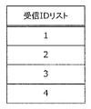
- FIG. 4 is a diagram showing an example of the reception ID list in the present embodiment.
- the reception ID list is a list of message IDs of messages that the gateway 300 receives and processes.
- the ID of the message is stored in each line of the reception ID list.
- the message IDs are “1”, “2”, “3”, and “4”, and the gateway 300 receives messages of these message IDs.
- the gateway 300 stops receiving a message with a message ID that is not included in the reception ID list.
- the ID value and the number of IDs included in the reception ID list are examples for explanation, and the configuration of the reception ID list used in the gateway 300 is not limited to this.
- FIG. 5 is a diagram illustrating an example of a transfer rule in the present embodiment.
- the transfer rule stores a combination of a message transfer source bus and a transfer destination bus, and a transfer target message ID in each row.
- the first line of the transfer rule is a transfer source “bus 200a”, a transfer destination “bus 200b”, and an ID “*”, and the gateway 300 receives a message received from the bus 200a regardless of the ID.
- the rule is that the data is transferred to the bus 200b.
- the second line of the transfer rule is a transfer source “bus 200b”, a transfer destination “bus 200a”, and an ID “3”.
- the gateway 300 may receive a message with an ID “3” from the bus 200b. In this case, the data is transferred to the bus 200a.
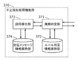
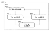
- FIG. 6 is a block diagram illustrating an example of the fraud detection processing function group 370 included in the gateway 300 according to the present embodiment.
- the fraud detection processing function group 370 includes a period determination unit 371, a rule determination information holding unit 372, an arbitration detection unit 373, and a received message information holding unit 374.
- these configurations indicate functions, and a program held in the storage unit in the gateway 300 is read and executed by the processing unit, and predetermined data is held in the storage unit.
- these configurations may be realized by performing transmission / reception of data via the input / output unit instead of recording predetermined data in the storage unit.
- these configurations may be realized by a combination of the above.
- the cycle determination unit 371 determines, for each message having the same ID, whether the cycle (elapsed time) in which the message is received is within a range where it can be determined that the message is normal.
- the cycle determination unit 371 acquires the message ID from the message received from the frame processing unit 350 and acquires information necessary to determine the cycle related to the ID. Specifically, the rule and the previous reception time are acquired from the rule determination information holding unit 372.
- the period determination unit 371 obtains a difference between the time when the current message is received and the previous reception time acquired from the rule determination information holding unit 372, and the difference value (elapsed time) is obtained from the rule determination information holding unit 372. It is determined whether it falls within the range indicated by the acquired rule.
- the cycle determination unit 371 determines that the elapsed time is within the range indicated by the rule, and determines that the elapsed time is out of the range indicated by the rule.
- the rule may be information on the upper limit and the lower limit of the elapsed time since the previous message with the same ID was received.
- the rule may be information on a reference elapsed time value and a range width determined to be OK from the reference time.
- the determination in the period determination unit 371 is to determine whether or not the difference between the message reception time and the previous reception time is within the range indicated by the rule, but is not limited thereto.
- the period determination unit 371 obtains the expected reception time range by adding the elapsed time range indicated by the rule to the previous reception time, and the reception time of the message received this time is the expected reception time range. You may determine whether it is contained in.
- the cycle determination unit 371 inquires of the arbitration detection unit 373 whether arbitration has occurred when a message is received.
- the period determination unit 371 acquires information indicating whether or not arbitration has occurred from the arbitration detection unit 373 and, if arbitration has occurred, acquires the start time of the arbitration that has occurred.
- the period determination unit 371 determines NG and arbitration has occurred, or if the arbitration start time is earlier than the upper limit of the range indicated by the rule, that is, if the value is small, the determination is OK. Change to If no arbitration has occurred, the determination remains NG and is not changed.
- the cycle determination unit 371 may inquire whether or not arbitration has occurred to the arbitration detection unit 373 each time a message is received. Further, the arbitration detection unit 373 may be inquired whether or not arbitration has occurred only when the determination on the rule acquired from the rule determination information holding unit 372 is NG.
- the period determination unit 371 inquires whether the arbitration detection unit 373 has arbitrated only when the determination for the rule acquired from the rule determination information holding unit 372 is NG, the period determination unit 371 receives the message. Each time the message is received, the mediation detection unit 373 is notified of the message reception time or the reception time is stored in the received message information holding unit 374.
- the period determination unit 371 may change the determination to OK when the arbitration detection unit 373 has arbitration, and when the message reception time is smaller than the reference elapsed time value.
- the period determination unit 371 notifies the rule determination information holding unit 372 of the reception time of the message received at that time.
- the rule determination information holding unit 372 holds a rule used by the cycle determination unit 371 and a message reception time for each ID included in the message.
- the rule may be information on the upper limit and the lower limit of the elapsed time since the previous message with the same ID was received. Further, it may be information indicating the width of a range determined to be OK from the reference elapsed time value and the reference elapsed time value.
- the arbitration detection unit 373 detects whether arbitration has occurred when receiving the message in response to an inquiry from the period determination unit 371.
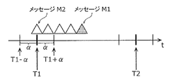
- 7A and 7B are diagrams illustrating message reception patterns when arbitration occurs in the present embodiment. 7A and 7B, a triangular symbol indicates one message, the horizontal axis indicates time, and T1 and T2 indicate times when messages are scheduled to be received. ⁇ indicates the width of a range in which the determination for the rule acquired from the rule determination information holding unit 372 is OK.
- time (T1- ⁇ ) is a lower limit value that the period determination unit 371 determines to be OK at time T1
- time (T1 + ⁇ ) is OK as the period determination unit 371 determines to be OK at time T1. This is the upper limit value to be determined.
- the message M1 and the message M3 are messages that the period determination unit 371 expects to receive at the time T1
- the message M2 and the message M4 are messages for which arbitration has been started.
- the arbitration detection unit 373 notifies the period determination unit 371 of the reception time of the message M2 or the message M4 as the arbitration start time.
- the arbitration detection unit 373 determines that arbitration has occurred when a message is received within a predetermined time interval. For example, in FIG. 7A, since messages are continuously transmitted from message M2 to message M1, it is determined that arbitration has occurred from message M2 to message M1. In FIG. 7B, since the time interval between the message M4 and the message M5 received at the time T1 before the message M4 is wide, it is determined that arbitration has occurred from the message M4.
- the arbitration detection unit 373 receives the message reception time from the period determination unit 371, acquires the reception time of the previous message stored in the received message information holding unit 374, and whether or not arbitration has occurred. Determine. When it is determined that arbitration has occurred, the arbitration detection unit 373 acquires arbitration occurrence state information that is information indicating whether or not arbitration has occurred from the received message information holding unit 374. When the acquired arbitration occurrence state information indicates that no arbitration has occurred, the arbitration detection unit 373 holds the message reception time in the received message information holding unit 374 as the arbitration occurrence start time. Further, the arbitration detection unit 373 holds the reception time of the current message as the reception time of the previous message in the reception message information holding unit 374 and holds the arbitration occurrence state information in the reception message information holding unit 374.
- the arbitration detection unit 373 determines whether arbitration has occurred from the reception time of the message when there is an inquiry from the period determination unit 371 whether arbitration has occurred. If arbitration has occurred, the arbitration occurrence start time is acquired from the received message information holding unit 374 and notified to the cycle determination unit 371 together with the determination result that arbitration has occurred. On the other hand, when the arbitration has not occurred, the arbitration detection unit 373 notifies only the determination result indicating that the arbitration has not occurred.
- the arbitration detection unit 373 notifies only the determination result indicating that no arbitration has occurred when no arbitration has occurred.
- the present invention is not limited to this.
- the mediation detection unit 373 may notify a value indicating the mediation occurrence start time together with the determination result, or may report the mediation occurrence start time when the previous mediation occurred.
- the received message information holding unit 374 holds the reception time of the previous message used by the arbitration detection unit 373, arbitration occurrence state information, and arbitration occurrence start time.
- the fraud detection processing function group 370 has been described as a function group that performs period determination, but is not limited thereto.
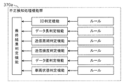
- FIG. 8 is a diagram showing another example of the fraud detection processing function group 370 in the present embodiment, and shows a modification of the fraud detection processing function group 370.
- the fraud detection processing function group 370a includes six types of determination functions. Specifically, as a determination function, an ID determination function that is a function that checks the ID field of a message, a data length determination function that is a function that checks the data length of a message, and a cycle (time interval) at which the message is transmitted is checked.
- a transmission cycle determination function that is a function for performing a transmission, a transmission frequency determination function that is a function for checking a frequency at which a message is transmitted, a data value determination function that is a function for checking a value (data value) of a data field of a message
- the vehicle state determination function is a function for recognizing the state of the vehicle based on the determination result of these determination functions, the transmission cycle, the frequency, the data value, or the amount of change in the data value and checking the vehicle state.
- the fraud detection processing function group 370a includes a comprehensive determination function that comprehensively determines whether or not the received message is an abnormal message from the determination results of these determination functions. The result of the comprehensive determination function becomes the result of fraud detection by the fraud detection processing function group 370a.
- the period determination unit 371, the rule determination information holding unit 372, the arbitration detection unit 373, and the received message information holding unit 374 in the fraud detection processing function group 370 in FIG. 6 are the fraud detection processing function group 370a in FIG.
- the transmission cycle determination function may be incorporated.
- these configurations are functional configurations, and the program stored in the storage unit in the gateway 300 is read and executed by the processing unit, and predetermined data is stored in the storage unit, or data is stored via the input / output unit. This is realized by performing transmission / reception. Alternatively, these configurations may be realized by a combination of the above.
- FIG. 9 is a block diagram showing an example of the ECU 100 included in the in-vehicle network system 10 according to the present embodiment.
- the ECU 100 includes a frame transmission / reception unit 110, a frame interpretation unit 120, a reception ID determination unit 130, a reception ID list holding unit 140, a frame processing unit 150, a data acquisition unit 170, and a frame generation unit 180.
- a frame transmission / reception unit 110 includes a frame transmission / reception unit 110, a frame interpretation unit 120, a reception ID determination unit 130, a reception ID list holding unit 140, a frame processing unit 150, a data acquisition unit 170, and a frame generation unit 180.
- the ECU 100 includes, for example, a processing unit realized by a processor, a storage unit realized by a semiconductor memory, an input / output unit realized by an input / output port, and the like. Provided as a device.
- the configuration showing the above functions is realized by reading and executing a program held in the storage unit by the processing unit, holding predetermined data in the storage unit, or executing data transmission / reception via the input / output unit Is done.
- these configurations may be realized by a combination of the above.
- the frame transmission / reception unit 110 transmits / receives a message according to the CAN protocol to / from the bus 200.
- the frame transmission / reception unit 110 reads the message sent to the bus 200 bit by bit, and transfers the read message to the frame interpretation unit 120.
- the frame transmission / reception unit 110 sends the message received from the frame generation unit 180 to the bus 200.
- the frame interpretation unit 120 receives the message value from the frame transmission / reception unit 110, and interprets the message so as to be mapped to each field in the CAN protocol.
- the frame interpretation unit 120 transfers the series of values interpreted as the ID field to the reception ID determination unit 130.
- the frame interpretation unit 120 transfers the value of the ID field of the message and the data field appearing after the ID field to the frame processing unit 150 or receives the message according to the determination result notified from the reception ID determination unit 130. Decide whether to cancel.
- the frame interpretation unit 120 determines that the received message is a message that does not comply with the CAN protocol, the frame interpretation unit 120 requests the frame generation unit 180 to transmit an error frame.
- the frame interpretation unit 120 determines that an error frame transmitted by another node has been received, the frame interpretation unit 120 discards the message being read.
- the reception ID determination unit 130 receives the value of the ID field from the frame interpretation unit 120. Then, according to the list of message IDs held by the reception ID list holding unit 140, it is determined whether or not the read message is received. The reception ID determination unit 130 notifies the frame interpretation unit 120 of the determination result.
- the reception ID list holding unit 140 holds a reception ID list received by the ECU 100. Since the reception ID list has the same format as in FIG. 4, the description thereof is omitted here.
- the frame processing unit 150 performs processing according to the received message data.
- the content of the process differs for each ECU 100.
- the ECU 100a when the ECU 100a receives a message indicating that the door is open when the speed of the automobile exceeds 30 km, the ECU 100a executes a process for sounding an alarm sound.
- the ECU 100c executes a process for sounding an alarm sound.
- the frame processing unit 150 causes the frame generation unit 180 to generate a frame to be transmitted to execute such processing.
- the data acquisition unit 170 acquires the data indicating the state of the device connected to the ECU 100 or the output data indicating the measurement value by the sensor and transfers the data to the frame generation unit 180.
- the frame generation unit 180 configures an error frame and sends it to the frame transmission / reception unit 110 in accordance with the error frame transmission request from the frame interpretation unit 120.
- the frame generation unit 180 forms a message frame by attaching a predetermined message ID to the data value received from the data acquisition unit 170, and sends the message frame to the frame transmission / reception unit 110.
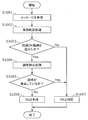
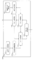
- FIG. 10 is a flowchart illustrating an example of fraud detection processing in the present embodiment.
- the period determination unit 371 of the fraud detection processing function group 370 receives a message from the frame processing unit 350 (step S1001).
- the cycle determination unit 371 determines whether or not the received message is within a range in which the cycle (elapsed time) of receiving the message can be determined to be normal for a message having the same ID (step S1002).
- step S1003 If the received message is not within the range where it can be determined that it is normal (Yes in step S1003), the cycle determination unit 371 proceeds to step S1004. If the received message is within the range in which it can be determined that it is normal (No in step S1003), cycle determination unit 371 proceeds to step S1007.
- step S1003 If it is determined in step S1003 that the message received by the period determination unit 371 is not within the range in which it can be determined to be normal (Yes in step S1003), the arbitration detection unit 373 determines whether arbitration has occurred during message reception. Is detected (step S1004).
- the arbitration detection unit 373 proceeds to step S1007 if arbitration has occurred when receiving a message (Yes in step S1005).
- the arbitration detection unit 373 proceeds to step S1006 when arbitration has not occurred at the time of message reception (No in step S1005).
- step S1005 when the arbitration detection unit 373 detects that arbitration has occurred (No in step S1005), the period determination unit 371 determines that the received message is not a normal message, that is, an abnormal message. It is determined that there is (step S1006). Thereafter, the fraud detection process in the fraud detection processing function group 370 is terminated.
- step S1003 when it is determined that the message received by the period determination unit 371 is within a range where it can be determined to be normal (No in step S1003), or in step S1005, the arbitration detection unit 373 performs arbitration when receiving a message.
- the period determining unit 371 determines that the received message is a normal message (step S1007). Thereafter, the fraud detection process in the fraud detection processing function group 370 is terminated.
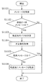
- FIG. 11 is a flowchart illustrating an example of transfer processing according to the present embodiment. Since the transfer process performed by the gateway 300 is substantially the same regardless of the transfer direction, an example will be described in which the gateway 300 transfers a message received from the bus 200a to the bus 200b.
- the frame transmitting / receiving unit 310 reads a message from the bus 200a (step S1101).
- the frame transmission / reception unit 310 notifies the frame interpretation unit 320 of data of each field of the read message.
- the frame interpretation unit 320 determines whether the message is a message to be received and processed from the ID field value (message ID) of the read message in cooperation with the reception ID determination unit 330 ( Step S1102). If the frame interpretation unit 320 determines that the message is not a target message (No in step S1102), the message is not transferred.
- step S1102 If frame interpreter 320 determines in step S1102 that the message is to be received and processed (Yes in step S1102), frame interpreter 320 transfers the value of each field in the message to frame processor 350. . Thereafter, the frame processing unit 350 determines a transfer destination bus according to the transfer rule held in the transfer rule holding unit 360 (step S1103).
- the frame processing unit 350 notifies the fraud detection processing function group 370 of the value of each field in the message received from the frame interpretation unit 320, and requests a determination as to whether or not it is an abnormal message.
- the fraud detection processing function group 370 determines whether the notified message is an abnormal message from the value of each field of the notified message, and notifies the frame processing unit 350 of the result of the determination (step). S1104).
- step S1104 determines in step S1104 that the message is an abnormal message (Yes in step S1105), the message is not transferred.
- step S1104 determines that the message is not an abnormal message but a normal message (No in step S1105)
- the frame processing unit 350 determines the message in step S1103.
- the frame generation unit 380 is requested to transfer to the transfer destination bus.
- the frame generation unit 380 receives the request from the frame processing unit 350, generates a message to be received by the designated transfer destination, and sends the message to the frame transmission / reception unit 310 (step S1106).
- step S1104 After determining the transfer destination of the received message (step S1103), it is determined whether this message is an abnormal message (step S1104), but the present invention is not limited to this. After determining whether the received message is an abnormal message, the transfer destination of this message may be determined. In addition, determination of the transfer destination of the received message and determination of whether it is an abnormal message may be performed in parallel.
- the fraud detection processing function group 370 monitors a message flowing through the network of the in-vehicle network system, and determines whether it has been delayed due to arbitration when the message is received after a predetermined period. Determine whether the message is abnormal.
- a technology that determines that fraud has occurred is normal or abnormal. It is possible to determine whether or not a message is an abnormal message with higher accuracy even for a message that is difficult to determine whether it is a message. As a result, the safety of the in-vehicle network system is improved.
- a fraud detection processing function group 370b is used instead of the fraud detection processing function group 370 of the first embodiment.
- the period determination unit uses the detection result of the arbitration detection unit 373 to determine the reception time of the message notified to the rule determination information holding unit.
- Such a fraud detection processing function group 370b can be included in the gateway 300 in place of the fraud detection processing function group 370 in FIG. 3 described in the first embodiment.
- gateway including the fraud detection processing function group 370b and the in-vehicle network system including the gateway are basically the same as those in the first embodiment, and thus the description of the configuration is omitted.
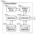
- FIG. 12 is a block diagram showing fraud detection processing function group 370b in the present embodiment. 12, the same components as those in FIG. 6 are denoted by the same reference numerals, and the description thereof is omitted. Further, illustration of a part of the same configuration is omitted.
- the fraud detection processing function group 370b will be described focusing on differences from the fraud detection processing function group 370.
- the fraud detection processing function group 370b includes a periodic start point determination unit 375 and a transmission type determination unit 376 in addition to the configuration of the fraud detection processing function group 370 in the first embodiment.
- the fraud detection processing function group 370b includes a cycle determination unit 371b instead of the cycle determination unit 371.
- the cycle start point determination unit 375 is used as a start point for calculating the elapsed time when the cycle determination unit 371b determines whether the cycle (elapsed time) in which the message is received is within a range where it can be determined to be normal. Determine the value of “Last received time”.
- the period start point determination unit 375 receives an inquiry from the period determination unit 371b, determines a value of “previous reception time” used as a start point for calculating the elapsed time, and notifies the period determination unit 371b.
- the cycle start point determination unit 375 In addition to the message received from the cycle determination unit 371b, the cycle start point determination unit 375 also acquires information on whether arbitration has occurred when the message is received, and determines whether arbitration has occurred. May be determined.
- the transmission type determination unit 376 determines the transmission type from the ID of the received message in response to the inquiry from the periodic start point determination unit 375 and notifies the periodic start point determination unit 375.
- FIG. 13 is a flowchart illustrating an example of fraud detection processing in the present embodiment. Steps common to those in FIG. 10 are indicated by the same reference numerals in FIG.
- the cycle type learning unit 377 determines the cycle type for each ID based on the information received from the cycle determination unit 371c. As a determination method, for example, the period type learning unit 377 records (accumulates) the reception time of a message received for each ID, and receives each ID for each ID at a timing when a certain number of reception times can be accumulated. The difference (elapsed time) from the reception time immediately before the time is obtained.
- the period type learning unit 377 records the reception time of the message received for each ID, and at the timing when a certain number of reception times can be accumulated, the reception time immediately before each reception time for each ID.
- the present invention is not limited to this.
- a predetermined threshold value (for upper limit and lower limit) is used for determining whether or not it is the same as the reference value, but is not limited to this.
- the same value may be used for the lower limit and the upper limit using one threshold value, and two values of the lower limit value and the upper limit value may be used instead of the combination of the reference value and the threshold value.
- the period type learning unit 377 sends the number of determination results ((1) about the same as the reference value, (2) shorter than the reference value, or (3) longer than the reference value) to the period type holding unit 378.
- the notification is made, but the present invention is not limited to this.
- the ratio may be notified, and if there is a value already held in the cycle type holding unit 378, the number obtained by adding the current value to the value may be notified.
- the period start point determination unit 375d sets the current reception time as the “previous reception time” for the first time when arbitration has occurred, and then a predetermined time or a predetermined ratio each time successive arbitrations occur.
- the time close to the scheduled reception time may be notified to the period determination unit 371b as the “previous reception time”.
- the time close to the scheduled reception time from the first time when arbitration has occurred may be notified to the period determination unit 371b as the “previous reception time”.
- the period start point determination unit 375d determines, in advance, how to notify the period determination unit 371b as the “previous reception time” of the time close to the scheduled reception time from the current reception time in advance for each ID, for example, It is calculated using a statistical numerical value such as degree or kurtosis, and the time calculated from the current reception time to the scheduled reception time by the previously calculated value is referred to as “previous reception”. You may notify to the period determination part 371b as time.
- each value may be used individually, or a value calculated from several values may be used. These may be learned by the periodic type learning unit 377.
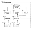
- FIG. 16 is a block diagram illustrating an example of an ECU in a modified example.
- ECU 100e shown in FIG. 16 further includes fraud detection processing function group 370.
- the frame processing unit 150 may request the fraud detection processing function group 370 to determine whether the message is an abnormal message, or the frame interpretation unit 120 may request it.
- FIG. 18 is a block diagram illustrating an example of an ECU in a modified example.
- the ECU 100g illustrated in FIG. 18 may include a transmission data acquisition unit 171 that acquires data to be transmitted to the bus 200 from another connected device or the outside.
- the fraud detection processing function group 370e included in the ECU 100g also determines whether or not the data received from the transmission data acquisition unit 171 is an abnormal message, and only when it is determined that the data is not an abnormal message, the frame generation unit 180. You may request to send a message.
- the configuration of the fraud detection processing function group 370e may be the same as the configuration of any of the fraud detection processing function groups 370, 370a, 370b, 370c, and 370d.
- the gateway or ECU 100 having the above-described fraud detection processing function group performs fraud detection processing while receiving a message, and when it is determined that the message is an abnormal message, the error frame is transmitted to receive from the network. The message may be invalidated.
- the gateway 300 or the ECU 100 having the above-described fraud detection processing function group further notifies the user of the occurrence of fraud or an external server, records the fraud occurrence in a log, or shifts the vehicle to the fail-safe mode. May be executed.
- a message is transmitted in plain text, but it may be encrypted.
- the message may include a message authentication code.
- CAN-FD CAN with Flexible Data Rate
- FlexRay FlexRay
- Ethernet LIN (Local Interconnect Network)
- MOST Media Oriented Systems Transport
- these networks may be combined as sub-networks.
- Each device in the above embodiment is specifically a computer including a microprocessor, a ROM (Read Only Memory), a RAM (Random Access Memory), a hard disk unit, a display unit, a keyboard, a mouse, and the like.
- a computer program is recorded in the RAM or hard disk unit.
- Each device achieves its functions by the microprocessor operating according to the computer program.
- the computer program is configured by combining a plurality of instruction codes indicating instructions for the computer in order to achieve a predetermined function.
- a part or all of the constituent elements of each device in the above embodiment may be configured by one system LSI (Large Scale Integration).
- the system LSI is an ultra-multifunctional LSI manufactured by integrating a plurality of components on a single chip, and specifically, a computer system including a microprocessor, ROM, RAM, and the like. .
- a computer program is recorded in the RAM.
- the system LSI achieves its functions by the microprocessor operating according to the computer program.
- the system LSI is used here, it may be referred to as an IC (Integrated Circuit), LSI, super LSI, or ultra LSI depending on the degree of integration. Further, the method of circuit integration is not limited to LSI's, and implementation using dedicated circuitry or general purpose processors is also possible.
- An FPGA Field Programmable Gate Array
- a reconfigurable processor that can reconfigure the connection or setting of circuit cells inside the LSI may be used.
- the present disclosure may be the method described above. Further, the present invention may be a computer program that realizes these methods by a computer, or may be a digital signal composed of a computer program.
- the present disclosure may transmit a computer program or a digital signal via an electric communication line, a wireless or wired communication line, a network represented by the Internet, data broadcasting, or the like.
- program or digital signal may be recorded on a recording medium and transferred, or the program or digital signal may be transferred via a network or the like, and may be implemented by another independent computer system.
- a technique for determining a message used as a reference for detecting unauthorized communication for the purpose of unauthorized control by an abnormal message is based on the embodiment and its modifications. explained.
- a message used as a reference for detecting unauthorized communication is determined by a gateway or ECU connected to the in-vehicle network system for communication, or a combination of these with a server computer.
- a system including one or more processors and a storage unit that executes such unauthorized communication detection is referred to as an unauthorized communication detection criterion determination system in the present disclosure.
- this technique is executed as a method including a part or all of the steps of processing executed by each component in the above-described embodiments or modifications thereof, or executed by the processor of the unauthorized communication detection criterion determination system. It can also be realized as a program for the unauthorized communication detection standard determination system to execute this method.
- In-vehicle network system 100, 100a, 100b, 100c, 100d, 100e, 100f, 100g ECU DESCRIPTION OF SYMBOLS 101 Engine 102 Brake 103 Door opening / closing sensor 104 Window opening / closing sensor 110 Frame transmission / reception part 120 Frame interpretation part 130 Reception ID determination part 140 Reception ID list holding part 150 Frame processing part 170 Data acquisition part 171 Transmission data acquisition part 180, 380 Frame generation part 200, 200a, 200b Bus 300 Gateway 310 Frame transmission / reception unit 320 Frame interpretation unit 330 Reception ID determination unit 340 Reception ID list holding unit 350 Frame processing unit 360 Transfer rule holding unit 370, 370a, 370b, 370c, 370d, 370e Fraud detection processing Function group 371, 371b, 371c Period determination unit 372 Rule determination information holding unit 373 Arbitration detection unit 374 Received message information holding unit 375, 375c, 37 d period starting point determining unit 376,376c transmission type determination section 377 periodically type learning unit 378 periodically type
Landscapes
- Engineering & Computer Science (AREA)
- Computer Security & Cryptography (AREA)
- Computer Networks & Wireless Communication (AREA)
- Signal Processing (AREA)
- Computing Systems (AREA)
- General Engineering & Computer Science (AREA)
- Computer Hardware Design (AREA)
- Health & Medical Sciences (AREA)
- General Health & Medical Sciences (AREA)
- Medical Informatics (AREA)
- Small-Scale Networks (AREA)
- Data Exchanges In Wide-Area Networks (AREA)
- Mobile Radio Communication Systems (AREA)
Priority Applications (7)
| Application Number | Priority Date | Filing Date | Title |
|---|---|---|---|
| CN201880022000.8A CN110546921B (zh) | 2018-03-29 | 2018-12-04 | 不正当检测方法、不正当检测装置以及程序 |
| EP18910237.9A EP3772200B1 (en) | 2018-03-29 | 2018-12-04 | Illicit act detection method, illicit act detection device, and program |
| EP23191161.1A EP4250648A3 (en) | 2018-03-29 | 2018-12-04 | Illicit act detection method, illicit act detection device, and program |
| JP2019516260A JP6527647B1 (ja) | 2018-03-29 | 2018-12-04 | 不正検知方法、不正検知装置及びプログラム |
| CN202211223548.3A CN115580471A (zh) | 2018-03-29 | 2018-12-04 | 不正当检测方法、不正当检测装置以及存储介质 |
| US16/583,996 US12155677B2 (en) | 2018-03-29 | 2019-09-26 | Fraud detection method, fraud detection device, and recording medium |
| US18/917,154 US20250039212A1 (en) | 2018-03-29 | 2024-10-16 | Fraud detection method, fraud detection device, and recording medium |
Applications Claiming Priority (2)
| Application Number | Priority Date | Filing Date | Title |
|---|---|---|---|
| JP2018-064431 | 2018-03-29 | ||
| JP2018064431 | 2018-03-29 |
Related Child Applications (1)
| Application Number | Title | Priority Date | Filing Date |
|---|---|---|---|
| US16/583,996 Continuation US12155677B2 (en) | 2018-03-29 | 2019-09-26 | Fraud detection method, fraud detection device, and recording medium |
Publications (1)
| Publication Number | Publication Date |
|---|---|
| WO2019187350A1 true WO2019187350A1 (ja) | 2019-10-03 |
Family
ID=68058721
Family Applications (1)
| Application Number | Title | Priority Date | Filing Date |
|---|---|---|---|
| PCT/JP2018/044568 Ceased WO2019187350A1 (ja) | 2018-03-29 | 2018-12-04 | 不正検知方法、不正検知装置及びプログラム |
Country Status (5)
| Country | Link |
|---|---|
| US (1) | US12155677B2 (enExample) |
| EP (2) | EP3772200B1 (enExample) |
| JP (3) | JP7280082B2 (enExample) |
| CN (1) | CN110546921B (enExample) |
| WO (1) | WO2019187350A1 (enExample) |
Cited By (3)
| Publication number | Priority date | Publication date | Assignee | Title |
|---|---|---|---|---|
| WO2021149651A1 (ja) | 2020-01-20 | 2021-07-29 | パナソニック インテレクチュアル プロパティ コーポレーション オブ アメリカ | 攻撃検知方法、攻撃検知システム、及びプログラム |
| JP2024005967A (ja) * | 2022-06-30 | 2024-01-17 | 本田技研工業株式会社 | 不正信号検出装置、車両及び不正信号検出方法 |
| US12413605B2 (en) | 2022-07-01 | 2025-09-09 | Honda Motor Co., Ltd. | Signal detection apparatus, vehicle, and method |
Families Citing this family (10)
| Publication number | Priority date | Publication date | Assignee | Title |
|---|---|---|---|---|
| US11700270B2 (en) * | 2019-02-19 | 2023-07-11 | The Aerospace Corporation | Systems and methods for detecting a communication anomaly |
| DE102019210225A1 (de) * | 2019-07-10 | 2021-01-14 | Robert Bosch Gmbh | Verfahren und Vorrichtung zur Analyse dienste-orientierter Kommunikation |
| US20210133594A1 (en) * | 2019-10-30 | 2021-05-06 | Dell Products L.P. | Augmenting End-to-End Transaction Visibility Using Artificial Intelligence |
| US20220407868A1 (en) * | 2019-12-05 | 2022-12-22 | Sumitomo Electric Industries, Ltd. | Detection device, vehicle, detection method, and detection program |
| EP4084418A4 (en) * | 2019-12-23 | 2023-01-25 | Panasonic Intellectual Property Corporation of America | DETERMINATION PROCESS, DETERMINATION SYSTEM AND PROGRAM |
| EP3979590B1 (en) * | 2020-04-29 | 2025-06-11 | Huawei Technologies Co., Ltd. | Method and device for identifying abnormal message |
| JP7651936B2 (ja) * | 2021-01-14 | 2025-03-27 | 株式会社オートネットワーク技術研究所 | 検知装置、検知方法および検知プログラム |
| JP7273875B2 (ja) | 2021-03-03 | 2023-05-15 | 本田技研工業株式会社 | 判定装置、移動体、判定方法及びプログラム |
| JP7759860B2 (ja) * | 2022-09-05 | 2025-10-24 | 本田技研工業株式会社 | 信号判定装置、移動体、信号判定方法、及びプログラム |
| JP7588121B2 (ja) * | 2022-09-28 | 2024-11-21 | 本田技研工業株式会社 | 車両制御システム、及び車両制御システムの制御方法 |
Citations (5)
| Publication number | Priority date | Publication date | Assignee | Title |
|---|---|---|---|---|
| WO2013094072A1 (ja) * | 2011-12-22 | 2013-06-27 | トヨタ自動車 株式会社 | 通信システム及び通信方法 |
| WO2014115455A1 (ja) | 2013-01-28 | 2014-07-31 | 日立オートモティブシステムズ株式会社 | ネットワーク装置およびデータ送受信システム |
| JP2016134913A (ja) * | 2015-01-20 | 2016-07-25 | パナソニック インテレクチュアル プロパティ コーポレーション オブ アメリカPanasonic Intellectual Property Corporation of America | 不正フレーム対処方法、不正検知電子制御ユニット及び車載ネットワークシステム |
| WO2017154828A1 (ja) * | 2016-03-10 | 2017-09-14 | 本田技研工業株式会社 | 通信システム |
| WO2018051607A1 (ja) * | 2016-09-15 | 2018-03-22 | 住友電気工業株式会社 | 検知装置、ゲートウェイ装置、検知方法および検知プログラム |
Family Cites Families (14)
| Publication number | Priority date | Publication date | Assignee | Title |
|---|---|---|---|---|
| FR2891680B1 (fr) * | 2005-09-30 | 2007-11-02 | Alcatel Sa | Systeme de commutation de paquets pour noeud de reseau de communication |
| JP5057304B2 (ja) * | 2007-06-08 | 2012-10-24 | 国立大学法人名古屋大学 | 車載通信システム及び車載通信方法 |
| JP2009143459A (ja) * | 2007-12-17 | 2009-07-02 | Hitachi Ltd | 車載エレクトロニクス・システム及び自動車 |
| JP4766160B2 (ja) * | 2009-07-29 | 2011-09-07 | 株式会社デンソー | 通信システムおよび通信ノード |
| JP5966957B2 (ja) * | 2013-02-08 | 2016-08-10 | トヨタ自動車株式会社 | ネットワーク監視装置及びネットワーク監視方法 |
| WO2015159520A1 (ja) * | 2014-04-17 | 2015-10-22 | パナソニック インテレクチュアル プロパティ コーポレーション オブ アメリカ | 車載ネットワークシステム、不正検知電子制御ユニット及び不正検知方法 |
| WO2016038816A1 (ja) * | 2014-09-12 | 2016-03-17 | パナソニック インテレクチュアル プロパティ コーポレーション オブ アメリカ | 車両用通信装置、車載ネットワークシステム及び車両用通信方法 |
| JP6306206B2 (ja) | 2014-11-20 | 2018-04-04 | 国立大学法人名古屋大学 | 通信制御装置及び通信システム |
| JP6282216B2 (ja) | 2014-11-20 | 2018-02-21 | 国立大学法人名古屋大学 | 通信システム及び通信装置 |
| CN111934966B (zh) * | 2014-12-01 | 2022-09-20 | 松下电器(美国)知识产权公司 | 不正常检测电子控制单元、车载网络系统以及不正常检测方法 |
| WO2016108963A1 (en) * | 2014-12-30 | 2016-07-07 | Battelle Memorial Institute | Temporal anomaly detection on automotive networks |
| US10798114B2 (en) * | 2015-06-29 | 2020-10-06 | Argus Cyber Security Ltd. | System and method for consistency based anomaly detection in an in-vehicle communication network |
| US10567400B2 (en) * | 2016-09-27 | 2020-02-18 | Fujitsu Limited | Attack detection device, attack detection method, and non-transitory computer-readable recording medium |
| JP7003544B2 (ja) * | 2017-09-29 | 2022-01-20 | 株式会社デンソー | 異常検知装置、異常検知方法、プログラム及び通信システム |
-
2018
- 2018-12-04 EP EP18910237.9A patent/EP3772200B1/en active Active
- 2018-12-04 EP EP23191161.1A patent/EP4250648A3/en not_active Withdrawn
- 2018-12-04 WO PCT/JP2018/044568 patent/WO2019187350A1/ja not_active Ceased
- 2018-12-04 CN CN201880022000.8A patent/CN110546921B/zh active Active
-
2019
- 2019-03-25 JP JP2019057269A patent/JP7280082B2/ja active Active
- 2019-09-26 US US16/583,996 patent/US12155677B2/en active Active
-
2023
- 2023-05-11 JP JP2023078576A patent/JP7512473B2/ja active Active
-
2024
- 2024-06-26 JP JP2024102810A patent/JP7699698B2/ja active Active
Patent Citations (6)
| Publication number | Priority date | Publication date | Assignee | Title |
|---|---|---|---|---|
| WO2013094072A1 (ja) * | 2011-12-22 | 2013-06-27 | トヨタ自動車 株式会社 | 通信システム及び通信方法 |
| WO2014115455A1 (ja) | 2013-01-28 | 2014-07-31 | 日立オートモティブシステムズ株式会社 | ネットワーク装置およびデータ送受信システム |
| JP2014146868A (ja) * | 2013-01-28 | 2014-08-14 | Hitachi Automotive Systems Ltd | ネットワーク装置およびデータ送受信システム |
| JP2016134913A (ja) * | 2015-01-20 | 2016-07-25 | パナソニック インテレクチュアル プロパティ コーポレーション オブ アメリカPanasonic Intellectual Property Corporation of America | 不正フレーム対処方法、不正検知電子制御ユニット及び車載ネットワークシステム |
| WO2017154828A1 (ja) * | 2016-03-10 | 2017-09-14 | 本田技研工業株式会社 | 通信システム |
| WO2018051607A1 (ja) * | 2016-09-15 | 2018-03-22 | 住友電気工業株式会社 | 検知装置、ゲートウェイ装置、検知方法および検知プログラム |
Cited By (5)
| Publication number | Priority date | Publication date | Assignee | Title |
|---|---|---|---|---|
| WO2021149651A1 (ja) | 2020-01-20 | 2021-07-29 | パナソニック インテレクチュアル プロパティ コーポレーション オブ アメリカ | 攻撃検知方法、攻撃検知システム、及びプログラム |
| US12261857B2 (en) | 2020-01-20 | 2025-03-25 | Panasonic Intellectual Property Corporation Of America | Attack detection method, attack detection system, and recording medium |
| JP2024005967A (ja) * | 2022-06-30 | 2024-01-17 | 本田技研工業株式会社 | 不正信号検出装置、車両及び不正信号検出方法 |
| US12418548B2 (en) | 2022-06-30 | 2025-09-16 | Honda Motor Co., Ltd. | Illegal signal detection apparatus, vehicle, and illegal signal detection method |
| US12413605B2 (en) | 2022-07-01 | 2025-09-09 | Honda Motor Co., Ltd. | Signal detection apparatus, vehicle, and method |
Also Published As
| Publication number | Publication date |
|---|---|
| EP3772200A4 (en) | 2021-05-19 |
| JP7699698B2 (ja) | 2025-06-27 |
| EP4250648A2 (en) | 2023-09-27 |
| EP3772200A1 (en) | 2021-02-03 |
| JP2024114822A (ja) | 2024-08-23 |
| EP4250648A3 (en) | 2023-12-06 |
| EP3772200B1 (en) | 2023-09-20 |
| CN110546921A (zh) | 2019-12-06 |
| JP7280082B2 (ja) | 2023-05-23 |
| CN110546921B (zh) | 2022-10-28 |
| JP2019176473A (ja) | 2019-10-10 |
| US20200021611A1 (en) | 2020-01-16 |
| US12155677B2 (en) | 2024-11-26 |
| JP2023090979A (ja) | 2023-06-29 |
| JP7512473B2 (ja) | 2024-07-08 |
Similar Documents
| Publication | Publication Date | Title |
|---|---|---|
| JP7699698B2 (ja) | 不正検知方法、不正検知装置及びプログラム | |
| US11356475B2 (en) | Frame transmission prevention apparatus, frame transmission prevention method, and in-vehicle network system | |
| JP7105279B2 (ja) | セキュリティ装置、攻撃検知方法及びプログラム | |
| US11296965B2 (en) | Abnormality detection in an on-board network system | |
| JP7030046B2 (ja) | 不正通信検知方法、不正通信検知システム及びプログラム | |
| JP7053449B2 (ja) | 不正通信検知基準決定方法、不正通信検知基準決定システム及びプログラム | |
| CN111066001B (zh) | 日志输出方法、日志输出装置以及存储介质 | |
| US11843477B2 (en) | Anomaly determination method, anomaly determination device, and recording medium | |
| JP2017112590A (ja) | 通信装置、通信方法、及び通信プログラム | |
| US20250039212A1 (en) | Fraud detection method, fraud detection device, and recording medium | |
| US12244607B2 (en) | Selection method, selection system, and recording medium | |
| WO2018020833A1 (ja) | フレーム伝送阻止装置、フレーム伝送阻止方法及び車載ネットワークシステム | |
| WO2017104122A1 (ja) | 通信装置、通信方法、及び通信プログラム |
Legal Events
| Date | Code | Title | Description |
|---|---|---|---|
| ENP | Entry into the national phase |
Ref document number: 2019516260 Country of ref document: JP Kind code of ref document: A |
|
| 121 | Ep: the epo has been informed by wipo that ep was designated in this application |
Ref document number: 18910237 Country of ref document: EP Kind code of ref document: A1 |
|
| NENP | Non-entry into the national phase |
Ref country code: DE |
|
| WWE | Wipo information: entry into national phase |
Ref document number: 2018910237 Country of ref document: EP |
|
| ENP | Entry into the national phase |
Ref document number: 2018910237 Country of ref document: EP Effective date: 20201029 |