WO2019182012A1 - ワイヤハーネス及びワイヤハーネスの製造方法 - Google Patents
ワイヤハーネス及びワイヤハーネスの製造方法 Download PDFInfo
- Publication number
- WO2019182012A1 WO2019182012A1 PCT/JP2019/011704 JP2019011704W WO2019182012A1 WO 2019182012 A1 WO2019182012 A1 WO 2019182012A1 JP 2019011704 W JP2019011704 W JP 2019011704W WO 2019182012 A1 WO2019182012 A1 WO 2019182012A1
- Authority
- WO
- WIPO (PCT)
- Prior art keywords
- metal pipe
- outer tube
- wire harness
- peripheral surface
- electric wire
- Prior art date
- Legal status (The legal status is an assumption and is not a legal conclusion. Google has not performed a legal analysis and makes no representation as to the accuracy of the status listed.)
- Ceased
Links
Images


Classifications
-
- B—PERFORMING OPERATIONS; TRANSPORTING
- B60—VEHICLES IN GENERAL
- B60R—VEHICLES, VEHICLE FITTINGS, OR VEHICLE PARTS, NOT OTHERWISE PROVIDED FOR
- B60R16/00—Electric or fluid circuits specially adapted for vehicles and not otherwise provided for; Arrangement of elements of electric or fluid circuits specially adapted for vehicles and not otherwise provided for
- B60R16/02—Electric or fluid circuits specially adapted for vehicles and not otherwise provided for; Arrangement of elements of electric or fluid circuits specially adapted for vehicles and not otherwise provided for electric constitutive elements
-
- H—ELECTRICITY
- H01—ELECTRIC ELEMENTS
- H01B—CABLES; CONDUCTORS; INSULATORS; SELECTION OF MATERIALS FOR THEIR CONDUCTIVE, INSULATING OR DIELECTRIC PROPERTIES
- H01B7/00—Insulated conductors or cables characterised by their form
-
- H—ELECTRICITY
- H01—ELECTRIC ELEMENTS
- H01B—CABLES; CONDUCTORS; INSULATORS; SELECTION OF MATERIALS FOR THEIR CONDUCTIVE, INSULATING OR DIELECTRIC PROPERTIES
- H01B7/00—Insulated conductors or cables characterised by their form
- H01B7/04—Flexible cables, conductors, or cords, e.g. trailing cables
-
- H—ELECTRICITY
- H01—ELECTRIC ELEMENTS
- H01B—CABLES; CONDUCTORS; INSULATORS; SELECTION OF MATERIALS FOR THEIR CONDUCTIVE, INSULATING OR DIELECTRIC PROPERTIES
- H01B7/00—Insulated conductors or cables characterised by their form
- H01B7/17—Protection against damage caused by external factors, e.g. sheaths or armouring
- H01B7/18—Protection against damage caused by wear, mechanical force or pressure; Sheaths; Armouring
- H01B7/20—Metal tubes, e.g. lead sheaths
-
- H—ELECTRICITY
- H02—GENERATION; CONVERSION OR DISTRIBUTION OF ELECTRIC POWER
- H02G—INSTALLATION OF ELECTRIC CABLES OR LINES, OR OF COMBINED OPTICAL AND ELECTRIC CABLES OR LINES
- H02G3/00—Installations of electric cables or lines or protective tubing therefor in or on buildings, equivalent structures or vehicles
- H02G3/02—Details
- H02G3/04—Protective tubing or conduits, e.g. cable ladders or cable troughs
Definitions
- the present invention relates to a wire harness and a manufacturing method thereof.
- a wire harness for a vehicle is provided with a protector for routing an electric wire along a predetermined routing route (see, for example, Patent Document 1).
- the protector of patent document 1 is provided with the protector main body which has a recessed part which can accommodate an electric wire, and the cover member which obstruct
- Both the protector body and the lid member are made of a synthetic resin material.
- the protector of the wire harness of patent document 1 is provided with a protector main body and a cover member, and has many components.
- An object of the present invention is to provide a wire harness capable of regulating a routing route with a simple configuration.
- a wire harness for achieving the above object includes an electric wire, a flexible outer tube through which the electric wire is inserted, and a metal pipe through which the outer tube is inserted.
- the wire harness in which the routing path of the outer tube is regulated portions of the inner peripheral surface of the metal pipe facing each other are in close contact with the outer peripheral surface of the outer tube.
- the wiring route of the electric wire and the outer tube is regulated by the metal pipe.
- the opposing portions of the inner peripheral surface of the metal pipe are in close contact with the outer peripheral surface of the outer tube, the displacement of the outer tube with respect to the metal pipe is suppressed. This eliminates the need for positioning the metal pipe with respect to the outer tube during the routing operation. Therefore, the routing route can be regulated with a simple configuration.
- the said wire harness WHEREIN It is preferable that the said metal pipe is provided in a part of length direction of the said exterior pipe
- an inner peripheral surface of the metal pipe is in close contact with an outer peripheral surface of the outer tube by deforming a partial cross-sectional shape in the length direction of the metal pipe. According to this configuration, it is possible to regulate the displacement of the outer tube with respect to the metal pipe only by deforming a partial cross-sectional shape in the length direction of the metal pipe.
- the metal pipe has a bent portion. According to this configuration, it is possible to change the wiring path of the electric wire and the outer tube according to the bending angle of the bent portion of the metal pipe.
- the said wire harness WHEREIN It is preferable that the inner peripheral surface of the said metal pipe and the outer peripheral surface of the said exterior tube are closely_contact
- the outer tube has a smaller outer diameter at a portion where the metal pipe and the outer tube are in close contact than an outer diameter of a portion located outside the metal pipe.
- a method of manufacturing a wire harness for achieving the above object includes an electric wire, a flexible outer tube through which the electric wire is inserted, and a metal pipe through which the outer tube is inserted, and the metal pipe Is a method of manufacturing a wire harness in which a wiring path of the electric wire and the outer tube is regulated, and includes a first step of inserting the outer tube into the metal pipe, and plastic deformation of the metal pipe A second step of closely contacting portions of the inner peripheral surface of the metal pipe facing each other to the outer peripheral surface of the outer tube.
- the inner peripheral surface of the metal pipe and the outer peripheral surface of the outer tube are brought into close contact with each other by plastically deforming the metal pipe.
- the routing route can be regulated with a simple configuration.
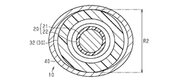
- FIG. 3 is a cross-sectional view taken along line 3-3 in FIG. 2.
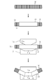
- FIG. 4 is a cross-sectional view taken along line 4-4 of FIG. Explanatory drawing which shows the manufacturing process of the wire harness of the embodiment in order.
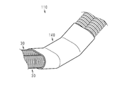
- the perspective view which expands and shows the part centering on the metal pipe in the wire harness of a modification.
- the wire harness 10 is routed in, for example, a hybrid vehicle or an electric vehicle, and electrically connects devices 91 and 92 such as a battery and an inverter, for example.
- the wire harness 10 includes an electric wire 20, a flexible outer tube 30 through which the electric wire 20 is inserted, and a metal pipe 40 through which the outer tube 30 is inserted.
- the wiring path of the electric wire 20 and the outer tube 30 is regulated by the metal pipe 40.
- the electric wire 20 has a core wire 21 and an insulating coating 22 that covers the outer periphery of the core wire 21.
- the core wire 21 is a stranded wire formed by twisting together a plurality of metal strands made of, for example, a copper alloy.
- the insulating coating 22 is made of an electrically insulating synthetic resin material.
- a terminal (not shown) connected to the device 91 (92) is fixed to the end of the core wire 21.
- the outer tube 30 is a cylindrical corrugated tube made of a synthetic resin material, and a small-diameter portion 31 and a large-diameter portion 32 in which both the inner diameter and the outer diameter are larger than the small-diameter portion 31 are the length of the outer tube 30. It has a structure provided alternately in the vertical direction. A portion of the large diameter portion 32 located outside the metal pipe 40 has a constant outer diameter R1 (see FIG. 2).
- the metal pipe 40 is made of, for example, an aluminum alloy and has a cylindrical shape. As shown in FIG. 2, the metal pipe 40 includes three straight portions (a first straight portion 40a, a second straight portion 40b, and a third straight portion 40c), and between the first straight portion 40a and the second straight portion 40b. And a second bent portion 42 positioned between the second straight portion 40b and the third straight portion 40c. The bent portion 41 (42) is located between the straight portions 40a and 40b (40b and 40c) adjacent to each other in the length direction of the metal pipe 40.
- the bending angle of the first bending portion 41 (the angle formed by the axis of the first straight portion 40a and the axis of the second straight portion 40b) and the bending angle of the second bending portion 42 (second straight)
- the angle formed by the axis of the portion 40b and the axis of the third straight portion 40c is equal.
- the cross-sectional shapes of the metal pipe 40 and the outer tube 30 at the opening position of the metal pipe 40 are both circular (substantially circular). Further, the inner diameter R0 of the metal pipe 40 at the opening position is larger than the outer diameter R1 of the large diameter portion 32 of the outer tube 30 at the opening position (R0> R1).
- the central portion (including the positions of the bent portions 41 and 42) of the metal pipe 40 in the length direction is compressed and plastically deformed in the radial direction (vertical direction in FIG. 2) of the metal pipe 40. ing.
- the cross-sectional shapes of the metal pipe 40 and the outer tube 30 in the central portion of the metal pipe 40 are both oval.
- the short-diameter portions (upper and lower portions in FIG. 4) are in close contact with the outer peripheral surface of the outer tube 30 in the central portion.
- the outer diameter R2 of the portion of the outer tube 30 that is in close contact with the inner peripheral surface of the metal pipe 40 is smaller than the outer diameter R1 of the portion of the outer tube 30 that is located outside the metal pipe 40 (R2 ⁇ R1). ).
- the procedure for manufacturing the wire harness 10 of the present embodiment will be described. As shown in FIG. 5, when manufacturing the wire harness 10, first, the outer tube 30 is inserted through the metal pipe 40 (the first step).
- the metal pipe 40 is plastically deformed by the press device 70 so that the mutually opposing portions of the inner peripheral surface of the metal pipe 40 are brought into close contact with the outer peripheral surface of the outer tube 30 (the second step).
- the press device 70 includes a fixed die 71 having a pressure surface 71a, and a movable die 72 having a pressure surface 72a opposite to the pressure surface 71a and provided close to and away from the fixed die 71. Yes.
- the metal pipe 40 through which the outer tube 30 is inserted is placed on the fixed mold 71.
- clamping is performed by moving the movable mold 72 closer to the fixed mold 71.
- the metal pipe 40 is plastically deformed into a shape along the pressing surfaces 71a and 72a.
- the wire harness 10 includes an electric wire 20, a flexible outer tube 30 through which the electric wire 20 is inserted, and a metal pipe 40 through which the outer tube 30 is inserted and which has a plurality of bent portions 41 and 42. Yes.
- the wiring path of the electric wire 20 and the outer tube 30 is regulated by the metal pipe 40. Portions of the inner peripheral surface of the metal pipe 40 facing each other are in close contact with the outer peripheral surface of the outer tube 30.
- the wiring path of the electric wire 20 and the outer tube 30 is regulated by the metal pipe 40 having the bent portions 41 and 42.
- the opposing portions of the inner peripheral surface of the metal pipe 40 are in close contact with the outer peripheral surface of the outer tube 30, the displacement of the outer tube 30 relative to the metal pipe 40 is suppressed.
- the positioning of the metal pipe 40 with respect to the outer tube 30 becomes unnecessary during the routing work. Therefore, the routing route can be regulated with a simple configuration.
- produced with the electricity supply to the electric wire 20 is directly transmitted to the inner peripheral surface of the metal pipe 40 from the outer peripheral surface of the exterior tube 30, and is discharged
- the metal pipe 40 is provided in a part of the length direction of the outer tube 30. According to such a configuration, the metal pipe 40 can be partially provided in a portion where the routing route of the outer tube 30 needs to be regulated. That is, it is possible to bend a portion of the outer tube 30 that is not covered by the metal pipe 40. Therefore, the freedom degree of the wiring work of the wire harness 10 can be raised, and a wiring work becomes easy.
- the inner peripheral surface of the metal pipe 40 is in close contact with the outer peripheral surface of the outer tube 30 by deforming a partial cross-sectional shape in the length direction of the metal pipe 40. According to such a configuration, the displacement of the outer tube 30 relative to the metal pipe 40 can be restricted only by deforming a partial cross-sectional shape in the length direction of the metal pipe 40.
- the manufacturing method of the wire harness 10 includes a first step of inserting the outer tube 30 into the metal pipe 40, a plurality of bent portions 41 and 42 formed by plastic deformation of the metal pipe 40, and the metal pipe 40 A second step of closely contacting the mutually facing portions of the inner peripheral surface with the outer peripheral surface of the outer tube 30.
- the effects (1), (3), and (4) can be achieved.
- the said embodiment can also be changed as follows, for example.
- each bending part 41 and 42 may mutually differ.
- the configuration may be such that the inner peripheral surface of the metal pipe 40 and the outer peripheral surface of the outer tube 30 are in close contact with each other only in the bent portions 41 and 42.
- the number of the bending parts provided in a metal pipe may be one, and may be three or more.
- a wire harness in which a plurality of outer tubes are inserted through one metal pipe may be used.
- the present invention can be embodied as a wire harness 110 in which two outer tubes 30 are inserted into one flat cylindrical metal pipe 140.
- -A metal pipe is not limited to what has a bending part, You may be comprised only by a straight part. It will be apparent to those skilled in the art that the present invention may be embodied in other specific forms without departing from the technical spirit thereof. For example, some of the parts described in the embodiment (or one or more aspects thereof) may be omitted, or some parts may be combined. The scope of the invention should be determined with reference to the appended claims, along with the full scope of equivalents to which such claims are entitled.
Landscapes
- Engineering & Computer Science (AREA)
- Insulated Conductors (AREA)
- Mechanical Engineering (AREA)
- Architecture (AREA)
- Civil Engineering (AREA)
- Structural Engineering (AREA)
- Details Of Indoor Wiring (AREA)
Abstract
ワイヤハーネス(10)は、電線(20)と、電線(20)が挿通された可撓性の外装管(30)と、外装管(30)が挿通された金属パイプ(40)とを備え、金属パイプ(40)により電線(20)及び外装管(30)の配索経路が規制される。金属パイプ(40)の内周面のうち互いに対向する部分が外装管(30)の外周面に密着している。
Description
本発明は、ワイヤハーネス及びその製造方法に関する。
従来、例えば車両用のワイヤハーネスには、所定の配索経路に沿って電線を配索するためのプロテクタが設けられている(例えば、特許文献1参照)。特許文献1のプロテクタは、電線を収容可能な凹部を有するプロテクタ本体と、凹部の開口を閉塞する蓋部材とを備えている。プロテクタ本体及び蓋部材は共に合成樹脂材料により形成されている。所定の配索経路に対応した形状のプロテクタを用いることにより、プロテクタ内に収容された電線の経路が規制される。
ところで、特許文献1に記載のワイヤハーネスのプロテクタは、プロテクタ本体及び蓋部材を備えるものであり、部品点数の多いものとなっている。
本発明の目的は、簡単な構成によって配索経路を規制できるワイヤハーネスを提供することにある。
本発明の目的は、簡単な構成によって配索経路を規制できるワイヤハーネスを提供することにある。
上記目的を達成するためのワイヤハーネスは、電線と、前記電線が挿通された可撓性の外装管と、前記外装管が挿通された金属パイプと、を備え、前記金属パイプにより前記電線及び前記外装管の配索経路が規制されるワイヤハーネスであって、前記金属パイプの内周面のうち互いに対向する部分が前記外装管の外周面に密着している。
同構成によれば、金属パイプにより電線及び外装管の配索経路が規制される。特に、金属パイプの内周面のうち互いに対向する部分が外装管の外周面に密着しているため、金属パイプに対する外装管の変位が抑制される。これにより、配索作業の際に外装管に対する金属パイプの位置決めが不要となる。したがって、簡単な構成によって配索経路を規制することができる。
上記ワイヤハーネスにおいて、前記金属パイプは、前記外装管の長さ方向の一部に設けられていることが好ましい。
同構成によれば、外装管の配索経路を規制する必要のある部分に金属パイプを部分的に設けることができる。すなわち、外装管のうち金属パイプによって覆われない部分を曲げることが可能となる。したがって、ワイヤハーネスの配索作業の自由度を高めることができ、配索作業が簡単となる。
同構成によれば、外装管の配索経路を規制する必要のある部分に金属パイプを部分的に設けることができる。すなわち、外装管のうち金属パイプによって覆われない部分を曲げることが可能となる。したがって、ワイヤハーネスの配索作業の自由度を高めることができ、配索作業が簡単となる。
上記ワイヤハーネスにおいて、前記金属パイプの長さ方向の一部の断面形状が変形されることで前記金属パイプの内周面が前記外装管の外周面に密着していることが好ましい。
同構成によれば、金属パイプの長さ方向の一部の断面形状を変形させるだけで金属パイプに対する外装管の変位を規制することができる。
同構成によれば、金属パイプの長さ方向の一部の断面形状を変形させるだけで金属パイプに対する外装管の変位を規制することができる。
上記ワイヤハーネスにおいて、前記金属パイプは屈曲部を有していることが好ましい。
同構成によれば、金属パイプの屈曲部の屈曲角度に応じて電線及び外装管の配索経路を変更することができる。
同構成によれば、金属パイプの屈曲部の屈曲角度に応じて電線及び外装管の配索経路を変更することができる。
上記ワイヤハーネスにおいて、前記金属パイプの内周面と前記外装管の外周面とが前記屈曲部にて密着していることが好ましい。
同構成によれば、金属パイプを塑性変形させて屈曲部を形成する際に、金属パイプの内周面と外装管の外周面とを密着させることができる。したがって、ワイヤハーネスの製造工程を簡単にすることができる。
同構成によれば、金属パイプを塑性変形させて屈曲部を形成する際に、金属パイプの内周面と外装管の外周面とを密着させることができる。したがって、ワイヤハーネスの製造工程を簡単にすることができる。
上記ワイヤハーネスにおいて、前記外装管は、前記金属パイプの外部に位置する部分の外径よりも前記金属パイプと前記外装管とが密着する部分の外径が小さいことが好ましい。
また、上記目的を達成するためのワイヤハーネスの製造方法は、電線と、前記電線が挿通された可撓性の外装管と、前記外装管が挿通された金属パイプと、を備え、前記金属パイプにより前記電線及び前記外装管の配索経路が規制されるワイヤハーネスを製造する方法であって、前記金属パイプに前記外装管を挿通する第1工程と、前記金属パイプを塑性変形させることにより前記金属パイプの内周面のうち互いに対向する部分を前記外装管の外周面に密着させる第2工程と、を備える。
同方法によれば、金属パイプに外装管を挿通した後に、金属パイプを塑性変形させることにより金属パイプの内周面と外装管の外周面とが密着される。これにより、金属パイプにより電線及び外装管の配索経路が規制されるとともに、金属パイプに対する外装管の変位が抑制される。また、配索作業の際に外装管に対する金属パイプの位置決めが不要となる。
したがって、簡単な構成によって電線及び外装管の経路規制をすることができる。
本発明によれば、簡単な構成によって配索経路を規制することができる。
以下、図1~図5を参照して、ワイヤハーネス10の一実施形態について説明する。
図1に示すように、ワイヤハーネス10は、例えばハイブリッド車や電気自動車に配索されるものであり、例えばバッテリやインバータなどの機器91,92同士を電気的に接続する。
図1に示すように、ワイヤハーネス10は、例えばハイブリッド車や電気自動車に配索されるものであり、例えばバッテリやインバータなどの機器91,92同士を電気的に接続する。
図1~図3に示すように、ワイヤハーネス10は、電線20と、電線20が挿通された可撓性の外装管30と、外装管30が挿通された金属パイプ40とを備えている。金属パイプ40により電線20及び外装管30の配索経路が規制される。
電線20は、芯線21と芯線21の外周を覆う絶縁被覆22とを有している。芯線21は、例えば、銅合金からなる複数本の金属素線を撚り合わせて形成される撚り線である。絶縁被覆22は、電気絶縁性の合成樹脂材料からなる。芯線21の端部には、機器91(92)に接続される端子(図示略)が固定されている。
外装管30は、合成樹脂材料からなる円筒状のコルゲート管であり、小径部31と、小径部31に比べて内径及び外径の双方が拡大された大径部32とが外装管30の長さ方向において交互に設けられた構造を有している。大径部32のうち金属パイプ40の外部に位置する部分は一定の外径R1を有している(図2参照)。
金属パイプ40は、例えばアルミニウム合金からなり、円筒状をなしている。
図2に示すように、金属パイプ40は、3つのストレート部(第1ストレート部40a,第2ストレート部40b,第3ストレート部40c)、第1ストレート部40aと第2ストレート部40bとの間に位置する第1屈曲部41、及び第2ストレート部40bと第3ストレート部40cとの間に位置する第2屈曲部42を有している。屈曲部41(42)は、金属パイプ40の長さ方向において隣り合うストレート部40a,40b(40b,40c)の間に位置している。
図2に示すように、金属パイプ40は、3つのストレート部(第1ストレート部40a,第2ストレート部40b,第3ストレート部40c)、第1ストレート部40aと第2ストレート部40bとの間に位置する第1屈曲部41、及び第2ストレート部40bと第3ストレート部40cとの間に位置する第2屈曲部42を有している。屈曲部41(42)は、金属パイプ40の長さ方向において隣り合うストレート部40a,40b(40b,40c)の間に位置している。
なお、本実施形態では、第1屈曲部41の屈曲角度(第1ストレート部40aの軸線と第2ストレート部40bの軸線とのなす角度)と、第2屈曲部42の屈曲角度(第2ストレート部40bの軸線と第3ストレート部40cの軸線とのなす角度)とが等しい。
図3に示すように、金属パイプ40の開口位置における金属パイプ40及び外装管30の断面形状は共に円形状(略真円形状)をなしている。また、上記開口位置における金属パイプ40の内径R0は、上記開口位置における外装管30の大径部32の外径R1よりも大きい(R0>R1)。
図4に示すように、金属パイプ40の長さ方向の中央部分(屈曲部41,42の位置を含む)は、金属パイプ40の径方向(図2における上下方向)において圧縮されて塑性変形されている。
金属パイプ40の上記中央部分における金属パイプ40及び外装管30の断面形状は共に長円形状をなしている。
上記中央部分において金属パイプ40の内周面のうち短径部分(図4の上部及び下部)が外装管30の外周面に密着している。ここで、外装管30のうち金属パイプ40の内周面に密着する部分の外径R2は、外装管30のうち金属パイプ40の外部に位置する部分の外径R1よりも小さい(R2<R1)。
上記中央部分において金属パイプ40の内周面のうち短径部分(図4の上部及び下部)が外装管30の外周面に密着している。ここで、外装管30のうち金属パイプ40の内周面に密着する部分の外径R2は、外装管30のうち金属パイプ40の外部に位置する部分の外径R1よりも小さい(R2<R1)。
次に、図5を参照して、本実施形態のワイヤハーネス10を製造する手順について説明する。
図5に示すように、ワイヤハーネス10の製造に際しては、まず、金属パイプ40に外装管30を挿通する(以上、第1工程)。
図5に示すように、ワイヤハーネス10の製造に際しては、まず、金属パイプ40に外装管30を挿通する(以上、第1工程)。
続いて、プレス装置70により金属パイプ40を塑性変形させることにより金属パイプ40の内周面のうち互いに対向する部分を外装管30の外周面に密着させる(以上、第2工程)。
プレス装置70は、加圧面71aを有する固定型71と、上記加圧面71aに対向する加圧面72aを有し、固定型71に対して近接及び離間可能に設けられた可動型72とを備えている。
第2工程においては、まず、外装管30が挿通された金属パイプ40を固定型71に載置する。次に、可動型72を固定型71に対して接近させることにより型締めを行う。これにより、金属パイプ40が加圧面71a,72aに沿った形状に塑性変形される。
次に、本実施形態の作用効果について説明する。
(1)ワイヤハーネス10は、電線20と、電線20が挿通された可撓性の外装管30と、外装管30が挿通され、複数の屈曲部41,42を有する金属パイプ40とを備えている。金属パイプ40により電線20及び外装管30の配索経路が規制される。金属パイプ40の内周面のうち互いに対向する部分が外装管30の外周面に密着している。
(1)ワイヤハーネス10は、電線20と、電線20が挿通された可撓性の外装管30と、外装管30が挿通され、複数の屈曲部41,42を有する金属パイプ40とを備えている。金属パイプ40により電線20及び外装管30の配索経路が規制される。金属パイプ40の内周面のうち互いに対向する部分が外装管30の外周面に密着している。
こうした構成によれば、屈曲部41,42を有する金属パイプ40により電線20及び外装管30の配索経路が規制される。特に、金属パイプ40の内周面のうち互いに対向する部分が外装管30の外周面に密着しているため、金属パイプ40に対する外装管30の変位が抑制される。これにより、配索作業の際に外装管30に対する金属パイプ40の位置決めが不要となる。したがって、簡単な構成によって配索経路を規制することができる。
また上記構成によれば、電線20への通電に伴い発生したジュール熱が、外装管30の外周面から金属パイプ40の内周面へ直接伝達され、金属パイプ40から外部に放出されるようになる。したがって、ワイヤハーネス10の放熱性を向上させることができる。
(2)金属パイプ40は、外装管30の長さ方向の一部に設けられている。
こうした構成によれば、外装管30の配索経路を規制する必要のある部分に金属パイプ40を部分的に設けることができる。すなわち、外装管30のうち金属パイプ40によって覆われない部分を曲げることが可能となる。したがって、ワイヤハーネス10の配索作業の自由度を高めることができ、配索作業が簡単となる。
こうした構成によれば、外装管30の配索経路を規制する必要のある部分に金属パイプ40を部分的に設けることができる。すなわち、外装管30のうち金属パイプ40によって覆われない部分を曲げることが可能となる。したがって、ワイヤハーネス10の配索作業の自由度を高めることができ、配索作業が簡単となる。
(3)金属パイプ40の長さ方向の一部の断面形状が変形されることで金属パイプ40の内周面が外装管30の外周面に密着している。
こうした構成によれば、金属パイプ40の長さ方向の一部の断面形状を変形させるだけで金属パイプ40に対する外装管30の変位を規制することができる。
こうした構成によれば、金属パイプ40の長さ方向の一部の断面形状を変形させるだけで金属パイプ40に対する外装管30の変位を規制することができる。
(4)金属パイプ40の内周面と外装管30の外周面とが各屈曲部41,42にて密着している。
こうした構成によれば、金属パイプ40を塑性変形させて各屈曲部41,42を形成する際に、金属パイプ40の内周面と外装管30の外周面とを密着させることができる。したがって、ワイヤハーネス10の製造工程を簡単にすることができる。
こうした構成によれば、金属パイプ40を塑性変形させて各屈曲部41,42を形成する際に、金属パイプ40の内周面と外装管30の外周面とを密着させることができる。したがって、ワイヤハーネス10の製造工程を簡単にすることができる。
(5)ワイヤハーネス10の製造方法は、金属パイプ40に外装管30を挿通する第1工程と、金属パイプ40を塑性変形させることにより複数の屈曲部41,42を形成するとともに金属パイプ40の内周面のうち互いに対向する部分を外装管30の外周面に密着させる第2工程とを備えている。
こうした方法によれば、上記(1)、(3)、(4)の作用効果を奏することができる。
<変形例>
なお、上記実施形態は、例えば以下のように変更することもできる。
<変形例>
なお、上記実施形態は、例えば以下のように変更することもできる。
・各屈曲部41,42の屈曲角度が互いに異なっていてもよい。
・各屈曲部41,42のみにおいて、金属パイプ40の内周面と外装管30の外周面とが密着している構成であってもよい。
・各屈曲部41,42のみにおいて、金属パイプ40の内周面と外装管30の外周面とが密着している構成であってもよい。
・金属パイプに設けられる屈曲部の数は1つでもよいし、3つ以上であってもよい。
・複数本の外装管が1本の金属パイプに挿通されたワイヤハーネスであってもよい。例えば図6に示すように、2本の外装管30が1本の扁平筒状の金属パイプ140に挿通されたワイヤハーネス110として本発明を具体化することもできる。
・複数本の外装管が1本の金属パイプに挿通されたワイヤハーネスであってもよい。例えば図6に示すように、2本の外装管30が1本の扁平筒状の金属パイプ140に挿通されたワイヤハーネス110として本発明を具体化することもできる。
・金属パイプは屈曲部を有するものに限定されず、ストレート部のみによって構成されるものであってもよい。
本発明がその技術的思想から逸脱しない範囲で他の特有の形態で具体化されてもよいということは当業者にとって明らかであろう。例えば、実施形態(あるいはその1つ又は複数の態様)において説明した部品のうちの一部を省略したり、いくつかの部品を組合せてもよい。本発明の範囲は、添付の請求の範囲を参照して、請求の範囲が権利を与えられる均等物の全範囲と共に確定されるべきである。
本発明がその技術的思想から逸脱しない範囲で他の特有の形態で具体化されてもよいということは当業者にとって明らかであろう。例えば、実施形態(あるいはその1つ又は複数の態様)において説明した部品のうちの一部を省略したり、いくつかの部品を組合せてもよい。本発明の範囲は、添付の請求の範囲を参照して、請求の範囲が権利を与えられる均等物の全範囲と共に確定されるべきである。
10,110…ワイヤハーネス、20…電線、21…芯線、22…絶縁被覆、30…外装管、31…小径部、32…大径部、40,140…金属パイプ、40a…第1ストレート部、40b…第2ストレート部、40c…第3ストレート部、41…第1屈曲部、42…第2屈曲部、70…プレス装置、71…固定型、72…可動型、71a,72a…加圧面、91,92…機器
Claims (7)
- 電線と、
前記電線が挿通された可撓性の外装管と、
前記外装管が挿通された金属パイプと、を備え、
前記金属パイプにより前記電線及び前記外装管の配索経路が規制されるワイヤハーネスであって、
前記金属パイプの内周面のうち互いに対向する部分が前記外装管の外周面に密着している、
ワイヤハーネス。 - 前記金属パイプは、前記外装管の長さ方向の一部に設けられている、
請求項1に記載のワイヤハーネス。 - 前記金属パイプの長さ方向の一部の断面形状が変形されることで前記金属パイプの内周面が前記外装管の外周面に密着している、
請求項1または請求項2に記載のワイヤハーネス。 - 前記金属パイプは屈曲部を有している、
請求項1~請求項3のいずれか一項に記載のワイヤハーネス。 - 前記金属パイプの内周面と前記外装管の外周面とが前記屈曲部にて密着している、
請求項4に記載のワイヤハーネス。 - 前記外装管は、前記金属パイプの外部に位置する部分の外径よりも前記金属パイプと前記外装管とが密着する部分の外径が小さい
請求項1~請求項5のいずれか一項に記載のワイヤハーネス。 - 電線と、前記電線が挿通された可撓性の外装管と、前記外装管が挿通された金属パイプと、を備え、前記金属パイプにより前記電線及び前記外装管の配索経路が規制されるワイヤハーネスを製造する方法であって、
前記金属パイプに前記外装管を挿通する第1工程と、
前記金属パイプを塑性変形させることにより前記金属パイプの内周面のうち互いに対向する部分を前記外装管の外周面に密着させる第2工程と、を備える、
ワイヤハーネスの製造方法。
Applications Claiming Priority (2)
| Application Number | Priority Date | Filing Date | Title |
|---|---|---|---|
| JP2018056899A JP2019169380A (ja) | 2018-03-23 | 2018-03-23 | ワイヤハーネス及びワイヤハーネスの製造方法 |
| JP2018-056899 | 2018-03-23 |
Publications (1)
| Publication Number | Publication Date |
|---|---|
| WO2019182012A1 true WO2019182012A1 (ja) | 2019-09-26 |
Family
ID=67986254
Family Applications (1)
| Application Number | Title | Priority Date | Filing Date |
|---|---|---|---|
| PCT/JP2019/011704 Ceased WO2019182012A1 (ja) | 2018-03-23 | 2019-03-20 | ワイヤハーネス及びワイヤハーネスの製造方法 |
Country Status (2)
| Country | Link |
|---|---|
| JP (1) | JP2019169380A (ja) |
| WO (1) | WO2019182012A1 (ja) |
Families Citing this family (1)
| Publication number | Priority date | Publication date | Assignee | Title |
|---|---|---|---|---|
| JP2024046860A (ja) * | 2022-09-26 | 2024-04-05 | 矢崎総業株式会社 | ワイヤハーネスおよびワイヤハーネスの製造方法 |
Citations (2)
| Publication number | Priority date | Publication date | Assignee | Title |
|---|---|---|---|---|
| JPS5953615U (ja) * | 1982-09-30 | 1984-04-09 | 未来工業株式会社 | 可撓性自由端部を有する電線管用ノ−マルベンド |
| JPH07167374A (ja) * | 1993-12-13 | 1995-07-04 | Tokai Rubber Ind Ltd | 曲がりホース用プロテクタ |
-
2018
- 2018-03-23 JP JP2018056899A patent/JP2019169380A/ja active Pending
-
2019
- 2019-03-20 WO PCT/JP2019/011704 patent/WO2019182012A1/ja not_active Ceased
Patent Citations (2)
| Publication number | Priority date | Publication date | Assignee | Title |
|---|---|---|---|---|
| JPS5953615U (ja) * | 1982-09-30 | 1984-04-09 | 未来工業株式会社 | 可撓性自由端部を有する電線管用ノ−マルベンド |
| JPH07167374A (ja) * | 1993-12-13 | 1995-07-04 | Tokai Rubber Ind Ltd | 曲がりホース用プロテクタ |
Also Published As
| Publication number | Publication date |
|---|---|
| JP2019169380A (ja) | 2019-10-03 |
Similar Documents
| Publication | Publication Date | Title |
|---|---|---|
| US8653372B2 (en) | Wire harness | |
| CN102844940B (zh) | 电线连接方法及线束 | |
| JP6607405B2 (ja) | 導電路 | |
| WO2015166894A1 (ja) | ギヤードモータおよびその製造方法、ならびにダンパ装置 | |
| WO2012086687A1 (ja) | シールド導電体 | |
| WO2019182012A1 (ja) | ワイヤハーネス及びワイヤハーネスの製造方法 | |
| JP2009205982A (ja) | 導電体および導電体の製造方法 | |
| JP2018063763A (ja) | 導電路 | |
| US10236097B2 (en) | Wire harness | |
| JP6248989B2 (ja) | 電線の端子取付方法および端子取付構造 | |
| JP5459041B2 (ja) | 車両用導電路 | |
| JP7419996B2 (ja) | 絶縁電線及び多心ケーブル | |
| JP2013106485A (ja) | ワイヤーハーネス及びその経路規制部材 | |
| JP2017216102A (ja) | 導通接続部材 | |
| WO2017175701A1 (ja) | ワイヤハーネス | |
| US10937567B2 (en) | Conduction path and wire harness | |
| JP5223798B2 (ja) | 電線連結構造及びその電線連結構造を有する車両用導電路 | |
| WO2019172018A1 (ja) | ワイヤハーネス | |
| US10905039B2 (en) | Shielded conductive path and shielding pipe | |
| JP2006094619A (ja) | シールド導電路及びシールド導電路の製造方法 | |
| WO2015159667A1 (ja) | 電磁シールド部材及びワイヤーハーネス | |
| JP5445805B2 (ja) | 電線連結構造及びその電線連結構造を有する車両用導電路 | |
| JP2023023525A (ja) | 導体線 | |
| KR101476079B1 (ko) | 쉴드 도전체 | |
| JP7211615B2 (ja) | ヒーター及びそれに適するケーブル保持構造 |
Legal Events
| Date | Code | Title | Description |
|---|---|---|---|
| 121 | Ep: the epo has been informed by wipo that ep was designated in this application |
Ref document number: 19771161 Country of ref document: EP Kind code of ref document: A1 |
|
| NENP | Non-entry into the national phase |
Ref country code: DE |
|
| 122 | Ep: pct application non-entry in european phase |
Ref document number: 19771161 Country of ref document: EP Kind code of ref document: A1 |