WO2019181951A1 - 治療装置 - Google Patents
治療装置 Download PDFInfo
- Publication number
- WO2019181951A1 WO2019181951A1 PCT/JP2019/011487 JP2019011487W WO2019181951A1 WO 2019181951 A1 WO2019181951 A1 WO 2019181951A1 JP 2019011487 W JP2019011487 W JP 2019011487W WO 2019181951 A1 WO2019181951 A1 WO 2019181951A1
- Authority
- WO
- WIPO (PCT)
- Prior art keywords
- treatment
- probe
- unit
- mode
- instruction
- Prior art date
- Legal status (The legal status is an assumption and is not a legal conclusion. Google has not performed a legal analysis and makes no representation as to the accuracy of the status listed.)
- Ceased
Links
Images


Classifications
-
- B—PERFORMING OPERATIONS; TRANSPORTING
- B25—HAND TOOLS; PORTABLE POWER-DRIVEN TOOLS; MANIPULATORS
- B25J—MANIPULATORS; CHAMBERS PROVIDED WITH MANIPULATION DEVICES
- B25J9/00—Program-controlled manipulators
- B25J9/16—Program controls
- B25J9/1628—Program controls characterised by the control loop
- B25J9/1633—Program controls characterised by the control loop compliant, force, torque control, e.g. combined with position control
-
- A—HUMAN NECESSITIES
- A61—MEDICAL OR VETERINARY SCIENCE; HYGIENE
- A61B—DIAGNOSIS; SURGERY; IDENTIFICATION
- A61B34/00—Computer-aided surgery; Manipulators or robots specially adapted for use in surgery
- A61B34/30—Surgical robots
- A61B34/35—Surgical robots for telesurgery
-
- A—HUMAN NECESSITIES
- A61—MEDICAL OR VETERINARY SCIENCE; HYGIENE
- A61B—DIAGNOSIS; SURGERY; IDENTIFICATION
- A61B17/00—Surgical instruments, devices or methods
-
- A—HUMAN NECESSITIES
- A61—MEDICAL OR VETERINARY SCIENCE; HYGIENE
- A61B—DIAGNOSIS; SURGERY; IDENTIFICATION
- A61B17/00—Surgical instruments, devices or methods
- A61B17/22—Implements for squeezing-off ulcers or the like on inner organs of the body; Implements for scraping-out cavities of body organs, e.g. bones; for invasive removal or destruction of calculus using mechanical vibrations; for removing obstructions in blood vessels, not otherwise provided for
- A61B17/225—Implements for squeezing-off ulcers or the like on inner organs of the body; Implements for scraping-out cavities of body organs, e.g. bones; for invasive removal or destruction of calculus using mechanical vibrations; for removing obstructions in blood vessels, not otherwise provided for for extracorporeal shock wave lithotripsy [ESWL], e.g. by using ultrasonic waves
-
- A—HUMAN NECESSITIES
- A61—MEDICAL OR VETERINARY SCIENCE; HYGIENE
- A61B—DIAGNOSIS; SURGERY; IDENTIFICATION
- A61B34/00—Computer-aided surgery; Manipulators or robots specially adapted for use in surgery
- A61B34/30—Surgical robots
-
- A—HUMAN NECESSITIES
- A61—MEDICAL OR VETERINARY SCIENCE; HYGIENE
- A61B—DIAGNOSIS; SURGERY; IDENTIFICATION
- A61B34/00—Computer-aided surgery; Manipulators or robots specially adapted for use in surgery
- A61B34/70—Manipulators specially adapted for use in surgery
- A61B34/77—Manipulators with motion or force scaling
-
- A—HUMAN NECESSITIES
- A61—MEDICAL OR VETERINARY SCIENCE; HYGIENE
- A61B—DIAGNOSIS; SURGERY; IDENTIFICATION
- A61B8/00—Diagnosis using ultrasonic, sonic or infrasonic waves
- A61B8/42—Details of probe positioning or probe attachment to the patient
- A61B8/4209—Details of probe positioning or probe attachment to the patient by using holders, e.g. positioning frames
- A61B8/4218—Details of probe positioning or probe attachment to the patient by using holders, e.g. positioning frames characterised by articulated arms
-
- A—HUMAN NECESSITIES
- A61—MEDICAL OR VETERINARY SCIENCE; HYGIENE
- A61N—ELECTROTHERAPY; MAGNETOTHERAPY; RADIATION THERAPY; ULTRASOUND THERAPY
- A61N7/00—Ultrasound therapy
- A61N7/02—Localised ultrasound hyperthermia
-
- B—PERFORMING OPERATIONS; TRANSPORTING
- B25—HAND TOOLS; PORTABLE POWER-DRIVEN TOOLS; MANIPULATORS
- B25J—MANIPULATORS; CHAMBERS PROVIDED WITH MANIPULATION DEVICES
- B25J13/00—Controls for manipulators
- B25J13/08—Controls for manipulators by means of sensing devices, e.g. viewing or touching devices
- B25J13/085—Force or torque sensors
-
- A—HUMAN NECESSITIES
- A61—MEDICAL OR VETERINARY SCIENCE; HYGIENE
- A61B—DIAGNOSIS; SURGERY; IDENTIFICATION
- A61B90/00—Instruments, implements or accessories specially adapted for surgery or diagnosis and not covered by any of the groups A61B1/00 - A61B50/00, e.g. for luxation treatment or for protecting wound edges
- A61B90/06—Measuring instruments not otherwise provided for
- A61B2090/064—Measuring instruments not otherwise provided for for measuring force, pressure or mechanical tension
-
- A—HUMAN NECESSITIES
- A61—MEDICAL OR VETERINARY SCIENCE; HYGIENE
- A61B—DIAGNOSIS; SURGERY; IDENTIFICATION
- A61B90/00—Instruments, implements or accessories specially adapted for surgery or diagnosis and not covered by any of the groups A61B1/00 - A61B50/00, e.g. for luxation treatment or for protecting wound edges
- A61B90/36—Image-producing devices or illumination devices not otherwise provided for
- A61B90/37—Surgical systems with images on a monitor during operation
- A61B2090/378—Surgical systems with images on a monitor during operation using ultrasound
-
- A—HUMAN NECESSITIES
- A61—MEDICAL OR VETERINARY SCIENCE; HYGIENE
- A61N—ELECTROTHERAPY; MAGNETOTHERAPY; RADIATION THERAPY; ULTRASOUND THERAPY
- A61N7/00—Ultrasound therapy
- A61N2007/0052—Ultrasound therapy using the same transducer for therapy and imaging
-
- A—HUMAN NECESSITIES
- A61—MEDICAL OR VETERINARY SCIENCE; HYGIENE
- A61N—ELECTROTHERAPY; MAGNETOTHERAPY; RADIATION THERAPY; ULTRASOUND THERAPY
- A61N7/00—Ultrasound therapy
- A61N2007/0056—Beam shaping elements
- A61N2007/0065—Concave transducers
Definitions
- the present disclosure relates to a treatment apparatus that performs treatment using a treatment head attached to a robot arm.
- Patent Document 1 describes an ultrasonic treatment apparatus having a treatment head attached to the tip of a robot arm.
- the treatment head includes a diagnostic probe for ultrasonic diagnosis and an irradiation unit for irradiating focused ultrasonic waves (hereinafter, HIFU).
- HIFU is an abbreviation for High Intensity Focused Ultrasound.
- treatment is performed by observing the affected part of a patient using a diagnostic probe, and irradiating the affected part with HIFU using an irradiation part.
- the treatment is performed while moving the treatment head relative to the treatment target so that the focus of the HIFU coincides with the affected part.
- the affected part when observing the affected part, the affected part is observed in a state where the patient is pressed with a diagnostic probe in order to suppress movement of the organ due to respiration.
- the pressing state by the diagnostic probe changes.
- the pressing force decreases, the state of the organ changes, so that the affected part may be lost.
- the pressing force increases, the patient may be painful.
- One aspect of the present disclosure is to provide a technique for facilitating accurate robot operation according to a treatment scene.
- the treatment device includes a robot arm, a treatment head, a control unit, and a probe drive unit.
- the robot arm has 6 degrees of freedom.
- the treatment head is provided at the tip of the robot arm and has an irradiation unit and a diagnostic probe.
- the irradiation unit irradiates convergent ultrasonic waves.
- the diagnostic probe protrudes from the center of the irradiation unit toward the irradiation direction of the convergent ultrasound, and transmits / receives diagnostic ultrasound different from the convergent ultrasound.
- the control unit changes at least one of the position and posture of the treatment head by controlling the operation of the robot arm according to an input from the outside.
- the probe driving unit changes the protruding amount of the diagnostic probe with respect to the irradiation unit.
- the control unit performs at least synchronous control for synchronizing and driving the probe driving unit and the robot arm so that the relative position between the irradiation unit and the tip of the diagnostic probe changes while maintaining the tip position of the diagnostic probe. Execute.
- the position of the irradiation unit can be changed while maintaining the tip position of the diagnostic probe.
- the focused ultrasound can be focused while maintaining the pressing force on the treatment target by the diagnostic probe, and the increase in the pressing force on the treatment target can be suppressed.
- Robot operation can be easily realized.
- a treatment apparatus 1 illustrated in FIGS. 1 and 2 is an apparatus that performs treatment by irradiating a treatment target 101 supported by a treatment table 100 with focused ultrasound (hereinafter, HIFU).
- HIFU is an abbreviation for High Intensity Focused Ultrasound.
- the treatment device 1 includes a robot arm 2, a treatment head 3, an ultrasonic diagnostic device 4, a control unit 5, and a remote operation unit 6.
- the remote operation unit 6 is an example of an instruction input unit.
- the treatment head 3 is a device that irradiates a treatment target 101 such as a patient with a HIFU that is an ultrasound for treatment and a diagnostic ultrasound that is an ultrasound different from the HIFU.
- the treatment head 3 includes an irradiation unit 31, a diagnostic probe 32, a water bag 33, and a probe driving unit 34.
- the irradiation unit 31 has an irradiation surface formed in a concave surface, and irradiates the HIFU toward one point as a focal point.
- the distance from the irradiation unit 31 to the focal point is constant.
- the diagnostic probe 32 is a shaft-like member that protrudes from the center of the irradiation surface of the irradiation unit 31 toward the irradiation direction of the HIFU.
- the diagnostic probe 32 transmits and receives diagnostic ultrasonic waves at its tip.
- the diagnostic probe 32 irradiates diagnostic ultrasound toward a direction in which a central axis (hereinafter referred to as a probe axis) is extended, that is, a preset angle range centering on a protruding direction with respect to the irradiation unit 31, and the reflection thereof. Receive waves.
- the water bag 33 is a watertight bag that covers the irradiation unit 31 and the diagnostic probe 32.
- the water bag 33 is filled with water serving as a HIFU transmission medium in order to suppress attenuation of the HIFU irradiated from the irradiation unit 31. Further, both the diagnosis and treatment for the treatment target 101 are performed in a state where the water bag 33 of the treatment head 3 is in contact with the treatment target 101.
- shaft contacts the treatment object 101.
- the probe driving unit 34 is an actuator that moves the diagnostic probe 32 along the probe axis.
- the protruding amount of the diagnostic probe 32 with respect to the irradiation unit 31 (hereinafter referred to as probe position), and thus the relative position of the diagnostic probe 32 with respect to the irradiation unit 31. Change position.
- the robot arm 2 has a treatment head 3 attached to the tip thereof, and is used to control both the position and posture of the treatment head 3.
- the robot arm 2 includes an articulated arm 21, an arm driving unit 22, a force sensor 23, and a direct operation unit 24.
- the direct operation unit 24 is an example of an instruction input unit.
- the articulated arm 21 has a plurality of links connected by a plurality of joints, and realizes movement with six degrees of freedom.
- the arm drive unit 22 has a plurality of motors installed at each joint of the multi-joint arm 21.
- the arm driving unit 22 changes the shape of the articulated arm 21 in accordance with an instruction from the control unit 5.
- the force sensor 23 is provided at the tip of the articulated arm 21. That is, the treatment head 3 is attached to the tip of the multi-joint arm 21 and thus the tip of the robot arm 2 via the force sensor 23.
- the force sensor 23 detects the magnitude and direction of the force transmitted to the robot arm 2 via the treatment head 3 and notifies the control unit 5 of it.
- the direct operation unit 24 is provided near the tip of the robot arm 2 and is gripped by the operator 102 when the robot arm 2 is manually operated.
- the direct operation unit 24 has a plurality of switches S1 to S4 for inputting instructions to the control unit 5.
- the plurality of switches include an operation changeover switch S1, a control changeover switch S2, an adjustment instruction switch S3, and an evacuation instruction switch S4.
- the operation switch S1 is a switch that is operated when the operation mode of the robot arm 2 is switched between the manual mode and the remote mode.
- the manual mode is set when the robot arm 2 is manually operated.
- the remote mode is set when the robot arm 2 is remotely operated via the remote operation unit 6.
- the control changeover switch S2 is a switch that is operated when the control mode of the robot arm 2 is switched to any one of the free mode, the plane limited mode, and the rotation limited mode.
- the free mode is a control mode in which at least one of the position and posture of the treatment head 3 can be arbitrarily changed.
- the plane limited mode is a control mode in which the movement of the treatment head 3 is limited to movement on a designated plane set to include the base point.
- the rotation limited mode is a control mode in which the movement of the treatment head 3 is limited to a rotation operation around the base point.
- the base point is a point where the tip of the diagnostic probe 32 is located when the control mode is switched to the plane limited mode or the rotation limited mode.
- the adjustment instruction switch S3 is a switch operated to input an adjustment instruction when adjusting the focus of the HIFU.
- the retreat instruction switch S4 is a switch operated to input a retreat instruction when the diagnostic probe 32 is moved to a retreat position where the HIFU is blocked by the diagnostic probe 32.
- the remote operation unit 6 has functions necessary for remote control of the treatment apparatus 1 and is operated by the operator 103. Specifically, the remote operation unit 6 has at least a function of receiving an instruction input equivalent to the plurality of switches S1 to S4 included in the direct operation unit 24 and a function of receiving an instruction input related to the movement of the treatment head 3.
- the remote operation unit 6 may be a dedicated device, or may be, for example, a general-purpose personal computer in which an application necessary for remote control of the treatment device 1 is installed.
- the ultrasonic diagnostic apparatus 4 includes a diagnosis control unit 41 and a monitor 42.
- the diagnosis control unit 41 irradiates diagnostic ultrasound from the diagnostic probe 32 and performs image processing on the reflected wave received by the diagnostic probe 32, thereby expressing the internal state of the treatment target 101. Two-dimensional image data is generated.
- the diagnosis control unit 41 displays a diagnostic image based on the image data on the monitor 42 and supplies the image data to the control unit 5.
- the diagnosis control unit 41 displays a grid G having an interval according to the treatment accuracy by irradiation of the HIFU from the irradiation unit 31 on the diagnosis image so as to be superimposed on the diagnosis image. For example, if 5 mm treatment accuracy is required, a 5 mm square grid G is displayed on the monitor 42.
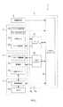
- the control unit 5 includes a microcomputer having a CPU 5a and a semiconductor memory (hereinafter referred to as memory) 5b such as RAM or ROM. Each function of the control unit 5 is realized by the CPU 5a executing a program stored in a non-transitional tangible recording medium.
- the memory 5b corresponds to a non-transitional tangible recording medium that stores a program. Also, by executing this program, a method corresponding to the program is executed.
- the control unit 5 may include one microcomputer or a plurality of microcomputers.
- the control unit 5 includes an arm controller 51, a HIFU controller 52, and a system controller 53 as functional unit blocks.
- the method of realizing the functions of the respective units included in the control unit 5 is not limited to software, and some or all of the functions may be realized using one or a plurality of hardware.
- the function is realized by an electronic circuit that is hardware, the electronic circuit may be realized by a digital circuit, an analog circuit, or a combination thereof.
- the arm controller 51 drives the arm drive unit 22 according to the detection result of the force sensor 23 and the instruction from the system controller 53 to change the shape of the articulated arm 21, so that the position and posture of the treatment head 3 are changed. Control at least one of them. Further, the arm controller 51 notifies the system controller 53 of the state of the robot arm 2 (hereinafter referred to as the arm state).
- the arm controller 51 is provided with an operation mode setting, a control mode setting, an adjustment instruction presence / absence, a retraction instruction presence / absence, and a treatment head 3 movement instruction as instructions from the system controller 53.
- the arm controller 51 executes different driving processes for each control mode. Details thereof will be described later.
- the arm controller 51 detects the magnitude and direction of the acting force that the operator 102 applies to the robot arm 2 by the force sensor 23, and instructs the movement of the treatment head 3 from the detection result. Generate. Then, the arm controller 51 calculates the control amount of each motor belonging to the arm driving unit 22 according to the generated movement instruction, and drives each motor.
- the arm controller 51 receives a treatment head 3 movement instruction input from the remote operation unit 6 and notified via the system controller 53, or a treatment calculated according to a preset program. An instruction to move the head 3 is acquired. Then, the arm controller 51 calculates the control amount of each motor belonging to the arm drive unit 22 according to the acquired movement instruction, and drives each motor.
- indication of the treatment head 3 shows a movement direction and a movement amount using a probe coordinate system.
- the probe coordinate system is a three-dimensional configuration in which the tip of the diagnostic probe 32, that is, the transmission / reception point of diagnostic ultrasound is the origin, the direction along the probe axis is the Z-axis direction, and the plane orthogonal to the Z-axis is the XY plane. Cartesian coordinate system.
- the X axis and the Y axis are set so that an image on the XZ plane is displayed on the monitor 42.
- the X axis of the probe coordinate system is represented by Xp
- the Y axis is represented by Yp
- the Z axis is represented by Zp.
- the HIFU controller 52 controls irradiation of the HIFU by the irradiation unit 31 in accordance with an instruction from the system controller 53. Further, the HIFU controller 52 drives the probe driving unit 34 according to an instruction from the system controller 53 to change the probe position. Further, the HIFU controller 52 notifies the system controller 53 of the probe position.
- the system controller 53 includes an input from the remote operation unit 6 or an input from the switch groups S1 to S4 of the direct operation unit 24, an arm state from the arm controller 51, a probe position from the HIFU controller 52, and a diagnosis control unit 41.
- the operation of the arm controller 51, the HIFU controller 52, and the display of the monitor 42 are controlled in accordance with the image data from.
- the system controller 53 executes at least target display processing, focus display processing, instruction calculation processing, and mode switching processing.
- the target display processing sets the target range T including the affected part to be irradiated with HIFU and notifies the diagnosis control unit 41 so that the target range is displayed on the diagnostic image on the monitor 42. T is displayed in a superimposed manner.
- the target range T may be, for example, an area extracted as an affected area by image processing on image data from the diagnosis control unit 41, or an area set in accordance with an input from the remote operation unit 6 after confirmation on the monitor 42 It may be.
- the focus position F of the HIFU is calculated from the arm state and the probe position and notified to the diagnosis control unit 41 so that the focus position F is superimposed on the diagnostic image of the monitor 42.
- a focus range (not shown) that is a range of focus positions that can be changed by changing the probe position is calculated and displayed on the monitor 42. Also good.
- the instruction calculation processing automatically generates a movement instruction for changing the arm state so that the probe axis passes through the center of the target range when the target range T is set.
- the instruction calculation process is executed when the operation mode is the remote mode and the setting for generating the movement instruction is made without using the input from the remote operation unit 6.
- the diagnostic probe 32 is set to an intermediate position within a range that can be taken by the probe position, for example.
- the position is not limited to this, and may be set at the most protruded position.
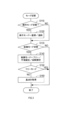
- the system controller 53 determines whether or not the operation mode has been switched via the remote operation unit 6 or the direct operation unit 24. If it is determined that the operation mode has not been switched, the process proceeds to S120. If it is determined that the operation mode has been switched, the process proceeds to S130.
- the system controller 53 sets the operation mode to either the manual mode or the remote mode according to the content of the switching operation that has been performed, and advances the process to S130.
- the system controller 53 determines whether or not the control mode has been switched via the remote operation unit 6 or the direct operation unit 24. If it is determined that the control mode has been switched, the process proceeds to S140. If it is determined that the control mode has not been switched, the process ends.
- the system controller 53 sets the control mode to any one of the free mode, the plane limited mode, and the rotation limited mode according to the contents of the switching operation that has been performed, and advances the process to S150.
- the system controller 53 determines whether or not the control mode set in S140 is the free mode. If it is determined that the set control mode is the free mode, the process ends. If it is determined that the set control mode is not the free mode but the plane limited mode or the rotation limited mode, the process proceeds to S160.
- the system controller 53 acquires the position of the tip of the diagnostic probe 32 as a base point, stores it in the memory 5b, and ends the process.
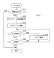
- the arm controller 51 determines whether or not there is an input of a movement instruction for changing at least one of the position and posture of the treatment head 3. If it is determined that there is a movement instruction input, the process proceeds to S220. If it is determined that there is no movement instruction input, the process ends.
- the movement instruction is calculated from the detection result of the force sensor 23 when the operation mode is the manual mode, and is input from the system controller 53 when the operation mode is the remote mode.
- the movement amount input from the system controller 53 may be input from the remote operation unit 6 or may be automatically generated by instruction calculation processing.
- the arm controller 51 calculates the control amount of the robot arm 2, that is, the control amount of each motor belonging to the arm drive unit 22, based on the instruction input and the arm state.
- the arm controller 51 changes at least one of the position and posture of the treatment head 3 by driving the arm driving unit 22 according to the control amount calculated in S220 to change the arm state.
- the arm controller 51 determines whether or not a force equal to or greater than a preset pressure threshold is detected by the force sensor 23.
- the pressure threshold is set to a size that does not cause pain to the treatment target 101 in consideration of the degree of pain that occurs in the treatment target 101 when the treatment head 3 is pressed against the treatment target 101. If it is determined that a force equal to or greater than the pressure threshold is detected, the process proceeds to S250. If it is determined that a force equal to or greater than the pressure threshold is not detected, the process proceeds to S260.
- the arm controller 51 performs synchronous control for driving the probe driving unit 34 via the HIFU controller 52 in synchronization with the arm driving unit 22 (that is, the movement of the robot arm 2). return.
- the probe drive unit 34 is driven so that the tip of the diagnostic probe 32 moves by a predetermined amount in the direction approaching the irradiation unit 31. Thereby, the pressing force to the treatment target 101 by the treatment head 3 is reduced.
- the arm controller 51 determines whether or not the driving of the robot arm 2 based on the processing in S230 is completed. If it is determined that the driving has not ended, the process returns to S240. If it is determined that the driving has been completed, the process ends.
- the probe position is changed by the processes of S240 to S260 until the pressing force is equal to or lower than the pressure threshold value. That is, it is possible to suppress the treatment object 101 from feeling painful with a change in at least one of the position and posture of the treatment head 3.
- a plane that includes the base point P acquired in the previous S160 and is parallel to the support surface 100a that supports the treatment target 101 in the treatment table 100 that supports the treatment target 101 is referred to as a designated plane.
- the arm controller 51 determines whether or not there is an input of a movement instruction for changing at least one of the position and posture of the treatment head 3. This determination is the same as in S110. If it is determined that there is a movement instruction input, the process proceeds to S320, and if it is determined that there is no movement instruction input, the process ends.
- the arm controller 51 determines whether or not the movement direction indicated by the movement instruction is the X-axis direction. If it is determined that the movement direction is the X-axis direction, the process proceeds to S330. If it is determined that the movement direction is not the X-axis direction, the process proceeds to S340.
- the arm controller 51 converts the amount of movement ⁇ Xp in the X-axis direction of the probe coordinate system indicated in the movement instruction into the amount of movement ⁇ Xh in the X-axis direction on the designated plane using equation (1). , The process proceeds to S350.
- ⁇ is the inclination of the designated plane in the X-axis direction with respect to the X-axis of the probe coordinate system.
- the arm controller 51 calculates the control amount of the robot arm 2 using the movement amount ⁇ Xh calculated in S330, and advances the process to S370. Specifically, the control amount of the robot arm 2 is set such that the position of the treatment head 3 is moved by the movement amount ⁇ Xh in the X-axis direction of the designated plane while maintaining the posture of the treatment head 3.
- the arm controller 51 determines whether or not the movement direction indicated by the movement instruction is the Y-axis direction. If it is determined that the moving direction is the Y-axis direction, the process proceeds to S360. If it is determined that the movement direction is not the Y-axis direction, that is, if it is determined that the movement direction is the Z-axis direction, the process proceeds to S380.
- the arm controller 51 uses the movement amount ⁇ Yp in the Y-axis direction of the probe coordinate system indicated in the movement instruction to calculate the control amount of the robot arm 2, and advances the process to S370.
- the control amount of the robot arm 2 is set so as to move the position of the treatment head 3 by ⁇ Yp in the Y-axis direction of the designated plane while maintaining the posture of the treatment head 3.
- the arm controller 51 changes the position of the treatment head 3 by driving the arm drive unit 22 and changing the arm state according to the control amount of the robot arm calculated in S340 or S360, and ends the process. .
- the arm controller 51 determines whether or not an adjustment instruction is input.
- the adjustment instruction is input from either the adjustment instruction switch S3 or the remote operation unit 6. If it is determined that no adjustment instruction has been input, the process is terminated. If it is determined that an adjustment instruction has been input, the process proceeds to S390.
- the arm controller 51 calculates the control amount of the robot arm 2 using the movement amount ⁇ Zp in the Z-axis direction indicated in the movement instruction. Specifically, the control amount of the robot arm 2 is set so as to move the position of the treatment head 3 by the movement amount ⁇ Zp in the Z-axis direction of the probe coordinate system while maintaining the posture of the treatment head 3. Furthermore, the arm controller 51 synchronizes with the movement of the robot arm 2 so that the tip position of the diagnostic probe 32 in the designated plane remains unchanged with respect to the movement of the treatment head 3 along the Z-axis direction. The control amount for changing is calculated.
- the arm controller 51 synchronizes and drives the arm driving unit 22 and the probe driving unit 34 according to the control amount of the robot arm 2 and the control amount of the probe position calculated in S390.
- the focus adjustment control is executed, and the process is terminated.
- the probe position changes while the distal end position of the diagnostic probe 32 is fixed, so that the HIFU focal position F in the treatment target 101 changes along the Z-axis direction as shown in FIG. .
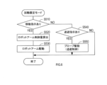
- the arm controller 51 determines whether or not there is an input of a movement instruction for changing at least one of the position and posture of the treatment head 3. If it is determined that there is a movement instruction input, the process proceeds to S520. If it is determined that there is no movement instruction input, the process proceeds to S540.
- the arm controller 51 calculates the control amount of the robot arm 2 according to the movement amounts ⁇ Xp and ⁇ Yp indicated in the movement instruction. Specifically, the control amount of the robot arm 2 is determined by moving the tip of the robot arm 2 to which the treatment head 3 is attached along the spherical surface acquired in S160 and centering on the base point. Is set to change.
- the arm controller 51 changes the posture of the treatment head 3 by driving the arm driving unit 22 according to the control amount calculated in S530, and ends the process.
- the arm controller 51 determines whether there is an input of a retreat instruction.
- the evacuation instruction is input from either the evacuation instruction switch S4 or the remote operation unit 6. If it is determined that no save instruction has been input, the process is terminated. If it is determined that a save instruction has been input, the process proceeds to S550.
- the arm controller 51 executes retreat control for driving the probe drive unit 34 so that the diagnostic probe 32 moves to the retreat position, and ends this processing.
- the retreat position is set to a position moved to the irradiation unit 31 side from the probe position in the initial state.
- the operation mode may be either the manual mode or the remote mode, and the setting of the operation mode may be switched at an arbitrary timing in the following procedure.
- the operator 102 or the operator 103 sets the control mode to the free mode, and causes the diagnostic probe 32 to transmit / receive diagnostic ultrasonic waves to display a diagnostic image on the monitor 42.
- the worker 102 or the operator 103 searches for a rough position of the affected part by arbitrarily changing at least one of the position and posture of the treatment head 3 while checking the diagnostic image.
- the distal end of the treatment head 3, that is, the distal end of the diagnostic probe 32 is brought into contact with the treatment object 101 and a search is performed in a state where a pressing force smaller than the pressure threshold is applied.
- the probe position changes in a direction to decrease the pressing force.
- the operator 102 or the operator 103 switches the control mode from the free mode to the plane limited mode.
- the position of the tip of the treatment head that is in contact with the treatment object 101, that is, the position of the tip of the diagnostic probe 32 is stored as the base point P.
- the movement of the treatment head 3 is limited to the designated plane.
- the Z axis of the probe coordinate system that is, the probe axis coincides with the vertical direction of the ground coordinate system
- the X axis Xh of the designated plane on the monitor 42 coincides with the X axis Xp of the probe coordinate system.
- the X axis Xh of the designated plane on the monitor 42 is the X axis of the probe coordinate system. It is inclined with respect to the direction Xp.
- the movement instruction along the X axis Xp direction of the probe coordinate system is converted into movement of the designated plane in the X axis Xh direction, and the movement amount is also converted to ⁇ Xh.
- the movement amount ⁇ Xh is a movement head after movement when the movement amount ⁇ Xh converted is moved in the Xh direction and when the movement amount ⁇ Xp before X conversion is moved in the Xp direction. 3 are set so that the Z axes coincide with each other. That is, if the movement amount ⁇ Xp is moved in the Xh direction without conversion, the treatment head 3 cannot be moved to a desired position confirmed using the grid on the monitor 42, for example, the front of the affected area. In other words, it is necessary to convert the movement amount in order to compensate for an error in the movement amount caused by moving along the designated plane.
- the treatment head 3 moves in the horizontal direction with respect to the treatment target 101 even when the posture of the treatment head 3 is tilted. Can be prevented from increasing and causing pain to the patient. Conversely, the pressing force on the treatment object 101 decreases as the treatment head 3 moves, and as a result, it is possible to suppress losing sight of the affected part due to movement of the built-in unit.
- the operator 102 or the operator 103 moves the treatment head 3 to the front of the affected area, and then inputs a movement instruction in the Z-axis direction together with the adjustment instruction, thereby adjusting the focal position of the HIFU.
- the monitor 42 is displayed so that the target range T is positioned in front of the treatment head 3, and the focal position F of the HIFU is also displayed.
- the amount of movement in the Z-axis direction can be easily specified so that the positions F overlap.
- treatment is performed by irradiating the irradiation unit 31 with HIFU.
- the control mode is set to the free mode, and the diagnostic probe 32 is caused to transmit / receive diagnostic ultrasound to display a diagnostic image on the monitor 42.
- the operator 102 or the operator 103 searches for an affected part by arbitrarily changing at least one of the position and posture of the treatment head 3 while checking the diagnostic image.
- the operator 102 or the operator 103 When the operator 102 or the operator 103 finds the affected area, the operator 102 or the operator 103 adjusts at least one of the position and posture of the treatment head 3 so that the affected area is located in front of the treatment head 3, and then sets the control mode to the rotation restriction mode. Switch. Before switching the control mode from the free mode to the rotation limited mode, the mode is temporarily switched to the plane limited mode, and after performing at least one of fine adjustment of the position and adjustment of the focal position, the control mode is changed to the rotation limited mode. You may switch. In any case, the position of the tip of the diagnostic probe 32 at the time of switching to the rotation limited mode is stored as the base point.
- the operator 102 or the operator 103 inputs the retraction instruction, and moves only the diagnostic probe 32 to the retraction position while maintaining both the position and the posture of the treatment head 3 as shown in FIG. . Thereby, it is possible to suppress the HIFU passing through the intercostal space from being blocked by the diagnostic probe 32.
- the operator 102 or the operator 103 performs treatment by irradiating the irradiation unit 31 with HIFU while changing the posture of the treatment head 3 around the base point P by inputting a movement instruction.
- the probe position of the diagnostic probe 32 is changed while holding the distal end position of the diagnostic probe 32 so that the pressing force applied to the treatment target 101 by the diagnostic probe 32 is smaller than the pressure threshold. Synchronous control is performed. For this reason, even if an operation that strongly presses the treatment head 3 against the treatment target 101 for some reason is performed, it is possible to prevent the treatment subject 101 from being painful.
- the tip position of the diagnostic probe 32 when the control mode is switched from the free mode to the plane limited mode or the rotation limited mode is used as the base point P.
- the movement of the arm 2 is limited to the movement restrained by the base point P.
- the movement of the treatment head 3 is limited to the movement along the designated plane including the base point P. Therefore, even when the posture of the treatment head 3 is inclined, the movement of the treatment head 3 is accompanied. It is possible to suppress an increase or decrease in the pressing force on the treatment target 101. As a result, it is possible to suppress the pressing force from increasing with the movement of the treatment head 3 and causing pain to the treatment target 101. Conversely, the pressing force decreases with the movement of the treatment head 3, and it is possible to suppress losing sight of the affected part due to the movement of the built-in part.
- the movement of the treatment head 3 is limited to the rotation about the base point P, so that the contact area between the treatment head 3 and the treatment object 101 is held in the intercostal space etc.
- the irradiation direction can be easily changed, and treatment can be performed efficiently.
- the diagnostic probe 32 is moved to the retracted position while holding both the position and the posture of the treatment head 3 by inputting the retract instruction in the rotation limited mode. For this reason, even when HIFU is irradiated from the intercostal space, the HIFU can be efficiently irradiated to the affected part without being blocked by the diagnostic probe 32.
- the monitor 42 is displayed in accordance with the probe coordinate system so that the Z axis coincides with the vertical direction of the screen and the X axis coincides with the horizontal direction of the screen.
- the present disclosure is limited to this. Is not to be done.
- the control mode is the plane limited mode, as shown in FIG. 11, the image may be tilted and displayed on the monitor so that the X axis of the limited coordinate plane matches the horizontal direction of the screen.
- the movement amount in the X-axis direction read from the monitor matches the movement amount in the X-axis direction within the limited coordinate plane, the movement amount can be used as it is without being converted.
- the support surface 100a of the treatment table 100 on which the treatment target 101 is supported coincides with the horizontal plane of the ground coordinate system, but the present disclosure is not limited to this.
- the support surface 100a may coincide with the vertical plane of the ground coordinate system.
- the synchronous control for making the pressing force on the treatment target 101 smaller than the pressure threshold is performed only in the free mode, but may be performed in another control mode.
- a plurality of functions of one constituent element in the above embodiment may be realized by a plurality of constituent elements, or a single function of one constituent element may be realized by a plurality of constituent elements. . Further, a plurality of functions possessed by a plurality of constituent elements may be realized by one constituent element, or one function realized by a plurality of constituent elements may be realized by one constituent element. Moreover, you may abbreviate
Landscapes
- Health & Medical Sciences (AREA)
- Engineering & Computer Science (AREA)
- Life Sciences & Earth Sciences (AREA)
- Surgery (AREA)
- General Health & Medical Sciences (AREA)
- Animal Behavior & Ethology (AREA)
- Veterinary Medicine (AREA)
- Biomedical Technology (AREA)
- Public Health (AREA)
- Nuclear Medicine, Radiotherapy & Molecular Imaging (AREA)
- Medical Informatics (AREA)
- Heart & Thoracic Surgery (AREA)
- Molecular Biology (AREA)
- Robotics (AREA)
- Radiology & Medical Imaging (AREA)
- Mechanical Engineering (AREA)
- Biophysics (AREA)
- Physics & Mathematics (AREA)
- Pathology (AREA)
- Human Computer Interaction (AREA)
- Orthopedic Medicine & Surgery (AREA)
- Vascular Medicine (AREA)
- Surgical Instruments (AREA)
- Ultra Sonic Daignosis Equipment (AREA)
Priority Applications (2)
| Application Number | Priority Date | Filing Date | Title |
|---|---|---|---|
| CN201980020447.6A CN111902095B (zh) | 2018-03-22 | 2019-03-19 | 治疗装置 |
| US17/010,790 US11786326B2 (en) | 2018-03-22 | 2020-09-02 | Treatment apparatus |
Applications Claiming Priority (2)
| Application Number | Priority Date | Filing Date | Title |
|---|---|---|---|
| JP2018054209A JP6859557B2 (ja) | 2018-03-22 | 2018-03-22 | 治療装置 |
| JP2018-054209 | 2018-03-22 |
Related Child Applications (1)
| Application Number | Title | Priority Date | Filing Date |
|---|---|---|---|
| US17/010,790 Continuation US11786326B2 (en) | 2018-03-22 | 2020-09-02 | Treatment apparatus |
Publications (1)
| Publication Number | Publication Date |
|---|---|
| WO2019181951A1 true WO2019181951A1 (ja) | 2019-09-26 |
Family
ID=67986264
Family Applications (1)
| Application Number | Title | Priority Date | Filing Date |
|---|---|---|---|
| PCT/JP2019/011487 Ceased WO2019181951A1 (ja) | 2018-03-22 | 2019-03-19 | 治療装置 |
Country Status (4)
| Country | Link |
|---|---|
| US (1) | US11786326B2 (https=) |
| JP (1) | JP6859557B2 (https=) |
| CN (1) | CN111902095B (https=) |
| WO (1) | WO2019181951A1 (https=) |
Cited By (1)
| Publication number | Priority date | Publication date | Assignee | Title |
|---|---|---|---|---|
| EP4070731A4 (en) * | 2019-12-05 | 2022-11-30 | Fuji Corporation | ULTRASONIC DIAGNOSTIC SYSTEM |
Families Citing this family (6)
| Publication number | Priority date | Publication date | Assignee | Title |
|---|---|---|---|---|
| EP4392838A4 (en) * | 2021-08-24 | 2024-11-27 | RMI Oceania Pty Ltd | DIAGNOSTIC IMAGING SYSTEM |
| US12409550B2 (en) * | 2022-01-12 | 2025-09-09 | Mantis Robotics, Inc. | Robot system with casing elements |
| WO2023181204A1 (ja) * | 2022-03-23 | 2023-09-28 | 株式会社Fuji | ロボット |
| CN115317814B (zh) * | 2022-09-13 | 2025-12-23 | 南京广慈医疗科技有限公司 | 一种带手臂支撑装置的超声理疗仪 |
| WO2024089812A1 (ja) * | 2022-10-26 | 2024-05-02 | 株式会社Fuji | ロボットシステム |
| WO2025052590A1 (ja) * | 2023-09-06 | 2025-03-13 | 株式会社Fuji | ロボットシステム |
Citations (4)
| Publication number | Priority date | Publication date | Assignee | Title |
|---|---|---|---|---|
| JPH0373139A (ja) * | 1989-05-15 | 1991-03-28 | Toshiba Corp | 音波治療装置 |
| JPH0576538A (ja) * | 1991-09-13 | 1993-03-30 | Shimadzu Corp | 超音波治療装置 |
| JPH0884740A (ja) * | 1994-09-16 | 1996-04-02 | Toshiba Corp | 治療装置 |
| JP2007516806A (ja) * | 2003-12-30 | 2007-06-28 | ライポソニックス, インコーポレイテッド | 脂肪組織の破壊のためのシステムおよび方法 |
Family Cites Families (17)
| Publication number | Priority date | Publication date | Assignee | Title |
|---|---|---|---|---|
| JPH0435660A (ja) | 1990-05-31 | 1992-02-06 | Toshiba Corp | 衝撃波治療装置 |
| JPH07213527A (ja) * | 1994-02-03 | 1995-08-15 | Toshiba Corp | 振動波治療装置 |
| JP3699046B2 (ja) * | 2002-01-09 | 2005-09-28 | 株式会社日立メディコ | 超音波治療装置 |
| JP2004000499A (ja) * | 2002-03-27 | 2004-01-08 | Aloka Co Ltd | 超音波医療システム |
| JP2005013283A (ja) * | 2003-06-23 | 2005-01-20 | Takeshi Shiina | 超音波探触子及び超音波診断装置 |
| JP3914199B2 (ja) * | 2003-11-11 | 2007-05-16 | 株式会社東芝 | 超音波治療装置 |
| JP2007330490A (ja) * | 2006-06-15 | 2007-12-27 | Ge Medical Systems Global Technology Co Llc | 超音波プローブ装置および超音波診断装置 |
| FR2924915B1 (fr) * | 2007-12-14 | 2011-01-07 | Technomed Medical Systems | Dispositif d'imagerie echographique et appareil de detection et de destruction de concretions solides incorporant un tel dispositif |
| US10542962B2 (en) * | 2009-07-10 | 2020-01-28 | Elekta, LTD | Adaptive radiotherapy treatment using ultrasound |
| JP5935344B2 (ja) * | 2011-05-13 | 2016-06-15 | ソニー株式会社 | 画像処理装置、画像処理方法、プログラム、記録媒体、および、画像処理システム |
| JP6042132B2 (ja) * | 2012-08-02 | 2016-12-14 | 株式会社日立製作所 | 超音波治療装置 |
| WO2015099849A1 (en) * | 2013-12-23 | 2015-07-02 | U-Systems, Inc. | Medical ultrasound scanning with control over pressure/force exerted by an ultrasound probe and/or a compression/scanning assembly |
| US10687909B2 (en) * | 2014-01-24 | 2020-06-23 | Koninklijke Philips N.V. | Robotic control of imaging devices with optical shape sensing |
| JP5701439B1 (ja) * | 2014-08-20 | 2015-04-15 | 医療法人 駿東育愛会 望星第一クリニック | 皮下診断装置及び血圧測定方法 |
| CN105816155B (zh) * | 2016-05-13 | 2019-01-25 | 福建师范大学 | 一种皮肤创面诊疗一体化探头及其实现方法 |
| CN106344066B (zh) * | 2016-08-26 | 2019-05-31 | 飞依诺科技(苏州)有限公司 | 探头机器人装置 |
| CN110087548B (zh) * | 2016-12-19 | 2023-06-27 | 皇家飞利浦有限公司 | 使用生理信息对解剖图像采集的控制 |
-
2018
- 2018-03-22 JP JP2018054209A patent/JP6859557B2/ja active Active
-
2019
- 2019-03-19 CN CN201980020447.6A patent/CN111902095B/zh active Active
- 2019-03-19 WO PCT/JP2019/011487 patent/WO2019181951A1/ja not_active Ceased
-
2020
- 2020-09-02 US US17/010,790 patent/US11786326B2/en active Active
Patent Citations (4)
| Publication number | Priority date | Publication date | Assignee | Title |
|---|---|---|---|---|
| JPH0373139A (ja) * | 1989-05-15 | 1991-03-28 | Toshiba Corp | 音波治療装置 |
| JPH0576538A (ja) * | 1991-09-13 | 1993-03-30 | Shimadzu Corp | 超音波治療装置 |
| JPH0884740A (ja) * | 1994-09-16 | 1996-04-02 | Toshiba Corp | 治療装置 |
| JP2007516806A (ja) * | 2003-12-30 | 2007-06-28 | ライポソニックス, インコーポレイテッド | 脂肪組織の破壊のためのシステムおよび方法 |
Cited By (1)
| Publication number | Priority date | Publication date | Assignee | Title |
|---|---|---|---|---|
| EP4070731A4 (en) * | 2019-12-05 | 2022-11-30 | Fuji Corporation | ULTRASONIC DIAGNOSTIC SYSTEM |
Also Published As
| Publication number | Publication date |
|---|---|
| JP2019165840A (ja) | 2019-10-03 |
| US20200397519A1 (en) | 2020-12-24 |
| JP6859557B2 (ja) | 2021-04-14 |
| CN111902095A (zh) | 2020-11-06 |
| CN111902095B (zh) | 2023-06-02 |
| US11786326B2 (en) | 2023-10-17 |
Similar Documents
| Publication | Publication Date | Title |
|---|---|---|
| WO2019181951A1 (ja) | 治療装置 | |
| EP2740435B1 (en) | Manipulator for medical use and surgery support device | |
| US20230172675A1 (en) | Controller, endoscope system, and control method | |
| CN103596521B (zh) | 用于引导对象的3d系统和方法 | |
| KR101772200B1 (ko) | Hifu 치료 헤드 및 이를 포함하는 hifu 장치 | |
| CN106999250A (zh) | 用于机器人辅助的医疗处理的系统 | |
| US20150320374A1 (en) | Diagnostic x-ray apparatus and diagnostic ultrasound apparatus | |
| JP7086381B2 (ja) | 治療装置 | |
| JP7337667B2 (ja) | 穿刺支援装置 | |
| CN118987518A (zh) | 超声治疗头的导航移动控制方法及所应用的超声波治疗装置 | |
| JP5117051B2 (ja) | 超音波診断システム及びその方法 | |
| JP2023121441A (ja) | 超音波診断装置、超音波プローブ、及び超音波プローブ用のアタッチメント | |
| Ning et al. | Cable-driven light-weighting and portable system for robotic medical ultrasound imaging | |
| CN107714178A (zh) | 手术导航定位机器人及其控制方法 | |
| CN107898499B (zh) | 骨科三维区域定位系统及方法 | |
| CN209884200U (zh) | 用于运动捕捉和控制机器人工具的系统 | |
| KR101672535B1 (ko) | 3차원 정보를 이용한 hifu 장치와 시스템 및 hifu 장치 제어방법 | |
| CN118354820B (zh) | 用于hifu治疗的显示装置 | |
| CN214857401U (zh) | 一体化系统结构装置 | |
| US20240130801A1 (en) | Robotic assisted imaging | |
| JP7576367B1 (ja) | Hifu照射装置 | |
| CN119367059B (zh) | 手术机器人系统、手术机器人打孔指引方法及装置 | |
| JP7725105B1 (ja) | Hifu照射装置 | |
| KR20250014380A (ko) | 위치조정부를 가지는 고주파암치료장치 | |
| CN121694803A (zh) | 超声波探头的操作辅助系统、记录介质及计算机程序产品 |
Legal Events
| Date | Code | Title | Description |
|---|---|---|---|
| 121 | Ep: the epo has been informed by wipo that ep was designated in this application |
Ref document number: 19771659 Country of ref document: EP Kind code of ref document: A1 |
|
| NENP | Non-entry into the national phase |
Ref country code: DE |
|
| 122 | Ep: pct application non-entry in european phase |
Ref document number: 19771659 Country of ref document: EP Kind code of ref document: A1 |