WO2019181734A1 - フィルタ制御方法、オーディオ処理方法、フィルタ制御装置、プログラムおよびフィルタエレメント - Google Patents
フィルタ制御方法、オーディオ処理方法、フィルタ制御装置、プログラムおよびフィルタエレメント Download PDFInfo
- Publication number
- WO2019181734A1 WO2019181734A1 PCT/JP2019/010577 JP2019010577W WO2019181734A1 WO 2019181734 A1 WO2019181734 A1 WO 2019181734A1 JP 2019010577 W JP2019010577 W JP 2019010577W WO 2019181734 A1 WO2019181734 A1 WO 2019181734A1
- Authority
- WO
- WIPO (PCT)
- Prior art keywords
- filter
- frequency
- parameters
- gain
- response
- Prior art date
- Legal status (The legal status is an assumption and is not a legal conclusion. Google has not performed a legal analysis and makes no representation as to the accuracy of the status listed.)
- Ceased
Links
Images




Classifications
-
- H—ELECTRICITY
- H04—ELECTRIC COMMUNICATION TECHNIQUE
- H04R—LOUDSPEAKERS, MICROPHONES, GRAMOPHONE PICK-UPS OR LIKE ACOUSTIC ELECTROMECHANICAL TRANSDUCERS; ELECTRIC HEARING AIDS; PUBLIC ADDRESS SYSTEMS
- H04R3/00—Circuits for transducers
- H04R3/04—Circuits for transducers for correcting frequency response
-
- H—ELECTRICITY
- H03—ELECTRONIC CIRCUITRY
- H03H—IMPEDANCE NETWORKS, e.g. RESONANT CIRCUITS; RESONATORS
- H03H17/00—Networks using digital techniques
- H03H17/02—Frequency selective networks
Definitions
- the present invention relates to a technique for controlling a filter that processes sound data.
- an acoustic device such as an equalizer is used.
- the equalizer is a filter that adjusts frequency characteristics.
- An example of the equalizer is a parametric equalizer (PEQ).
- the PEQ includes a plurality of filter elements that control the frequency characteristics of the input sound signal.
- the acoustic engineer (user) adjusts the filter coefficient of the equalizer through parameter settings such as the center frequency, bandwidth and gain of the band of each filter element, and the frequency characteristics of the sound radiated in the acoustic space (equalizer, amplifier) ,
- the frequency characteristics of the reproduction system including the speaker and the acoustic space) can be matched with the target characteristics (for example, Patent Document 1: FIG. 16).
- the frequency response of the flat element is the low-frequency side slope (lower slope) and the high-frequency side slope (upper slope), and the center where the gain is constant between both slopes.
- the lower slope part means a frequency response in a section where the gain rises (or falls) from the reference gain (0 decibel) to the specified value as the frequency increases, and the upper slope part increases the frequency. Is a frequency response in a section where the gain falls (or rises) from the specified value toward the reference gain (0 dB).
- Each of the upper inclined portion and the lower inclined portion of the flat element has a cosine curve shape.
- the conventional PEQ filter element group including a flat element including a flat element.
- the frequency characteristic of the reproduction system is inclined in a certain frequency band (for example, the volume level is higher as the frequency is lower)
- the frequency band cannot be controlled to a flat characteristic with one flat element,
- a filter element is required.
- the acoustic adjustment in an acoustic space such as a concert hall
- the conventional flat element cannot correct such inclination.
- the present invention has been made in view of the problems described above, and it is an object of the present invention to provide a technique that allows a user to easily perform the operation of adjusting the frequency characteristics of the reproduction system to the target characteristics in the PEQ. To do.
- a filter control method includes a plurality of parameters that define a frequency response, and a lower slope portion in which a gain changes on a low frequency side within a predetermined band.
- An audio processing method includes a plurality of parameters that define a frequency response, a lower inclined portion whose gain changes on a low frequency side within a predetermined band, and a high frequency band within the predetermined band.
- a plurality of parameters including a specific parameter defining a central slope portion where the gain changes between the upper slope portion where the gain changes on the side, and a response curve representing a frequency response of the filter is represented by the plurality of parameters.
- the filter coefficient of the filter is generated based on the response curve, and the filter coefficient is convolved with the sound data by the filter.
- a filter control apparatus is a filter control apparatus including one or more processors and a memory, and the frequency stored when the one or more processors execute a program stored in the memory.
- a plurality of parameters that define a response, and between a lower slope portion where the gain changes on a low frequency side within a predetermined band and an upper slope portion where the gain changes on a high frequency side within the predetermined band.
- a response curve representing a frequency response of a filter is generated based on the plurality of parameters, the filter including a specific parameter that defines a central slope where the gain changes, and the filter is generated based on the response curve.
- a program according to one aspect of the present invention is a computer that includes a plurality of parameters that define a frequency response, a lower inclined portion whose gain changes on a low frequency side within a predetermined band, and a high frequency within the predetermined band.
- a process of receiving the plurality of parameters including a specific parameter that defines a central slope portion in which the gain changes between the upper slope portion in which the gain changes on the band side, and a response curve representing the frequency response of the filter,
- a process of creating based on a plurality of parameters and a process of generating a filter coefficient of the filter based on the response curve are executed.
- a filter element is a filter element that controls frequency characteristics of a specific band of a sound signal, and the position and width of the specific band are controlled based on first and second parameters. Based on the third and fourth parameters, the slope and gain of the frequency response in the specific band of the filter are controlled.
- FIG. 2 is a diagram illustrating an example of a hardware configuration of an audio processing device 1.
- FIG. 6 is a diagram illustrating an example of a PEQ editing screen displayed on a display unit 141 of the audio processing device 1.
- FIG. It is a flowchart which shows the flow of the filter control process which CPU110 of the audio processing apparatus 1 performs according to a filter control program. It is a figure which shows an example of 6 types of parameters which prescribe
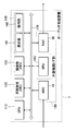
- FIG. 1 is a functional block diagram of an audio processing apparatus 1 according to an embodiment of the present invention.
- the audio processing device 1 is a PEQ for adjusting sound radiated from a speaker to an acoustic space such as a concert hall.
- the audio processing apparatus 1 includes an analog / digital converter 10, a filter 20, a digital / analog converter 30, a filter coefficient calculation unit 40, and a setting unit 50.
- the analog / digital converter 10 is represented as “ADC10”
- the digital / analog converter 30 is represented as “DAC30”.
- a sound source device such as an audio player is connected to the ADC 10, and a speaker (not shown in FIG. 1) installed in the acoustic space is connected to the DAC 30.
- An amplifier may be connected between the sound source device and the ADC 10, and an amplifier may be connected between the DAC 30 and the speaker.
- the ADC 10 performs analog / digital conversion on an analog input sound signal input from a sound source device such as a microphone, a musical instrument, or a recorder, and provides sound data as a conversion result to the filter 20.
- the filter 20 is a FIR (Finite Impulse Response) type filter that convolves a filter coefficient with sound data given from the ADC 10 to control the frequency characteristics of the sound data and outputs the sound data after convolution to the DAC 30.
- the DAC 30 converts the sound data from the filter 20 into an analog output sound signal and outputs it to the speaker.
- the setting unit 50 provides a user interface for allowing the user to set a plurality of types of parameters that define the frequency response of the filter 20.
- the setting unit 50 edits the value of the parameter in accordance with the parameter editing operation by the user, and gives the edited parameter to the filter coefficient calculation unit 40.
- the filter coefficient calculation unit 40 generates a filter coefficient corresponding to the parameter from the setting unit 50 and gives it to the filter 20.
- FIG. 2 is a block diagram illustrating an example of a hardware configuration of the audio processing apparatus 1.
- the audio processing device 1 includes a CPU (Central Processing Unit) 110, a nonvolatile memory 120, a volatile memory 130, a user interface unit 140, an external device interface unit 150, and a filter 20. It has a functioning SPU (Signal Processing Unit) 160 and a bus 170 that mediates data exchange between these components.
- the external device interface unit 150 is abbreviated as “external device I / F unit 150”.
- the nonvolatile memory 120 is a ROM (Read Only Memory), for example, and the volatile memory 130 is a RAM (Random Access Memory), for example.
- the nonvolatile memory 120 stores in advance a filter control program that causes the CPU 110 to execute a filter control method that characterizes the present embodiment.
- the volatile memory 130 is used by the CPU 110 as a work area when executing the filter control program.
- the CPU 110 is composed of one or more processors that execute programs.
- the CPU 110 functions as the filter coefficient calculation unit 40 (see FIG. 1) by executing the filter control program stored in the nonvolatile memory 120.
- the SPU 160 controls the frequency characteristics of the sound data by convolving the filter data of the FIR filter in the time domain with the sound data obtained by subjecting the input sound signal to A / D conversion. Note that the CPU 110 may convolve the filter coefficients instead of the SPU 160. In that case, the SPU 160 may be omitted.
- the SPU 160 may be a type that performs convolution of filter coefficients in the frequency domain.
- the SPU 160 converts the sound data in the time domain into sound data in the frequency domain by, for example, FFT, and multiplies the converted sound data by a filter coefficient.
- the SPU 160 obtains sound data in the time domain by inverse FFT on the sound data resulting from the multiplication.
- the external device I / F unit 150 is a collection of interfaces for connecting an external device such as a sound source device or a speaker to the audio processing device 1 via a signal line such as an audio cable. As shown in FIG. 2, the external device I / F unit 150 includes an ADC 10 and a DAC 30. The external device I / F unit 150 provides sound data that has undergone analog / digital conversion by the ADC 10 to the SPU 160 via the bus 170, receives sound data output from the SPU 160 via the bus 170, and provides it to the DAC 30.
- the external device I / F unit 150 inputs measurement data representing frequency characteristics measured in the reproduction system before adjustment by the audio processing device 1 to the audio processing device 1.
- a recording medium such as a USB memory that stores frequency characteristic measurement data measured in advance by another device is connected to the external device I / F unit 150, and the audio processing apparatus 1 reads reproduction measurement data from the recording medium. Is read.
- the microphone and the speaker installed in the acoustic space are connected to the external device I / F unit 150, and the audio processing device 1 itself radiates test sound (white noise or the like) from the speaker to the acoustic space.
- the sound in the acoustic space may be collected by a microphone, and reproduction measurement data may be generated from the collected sound.
- the user I / F unit 140 includes a display unit 141 such as a liquid crystal display and an operation unit 142 such as a mouse or a keyboard, and functions as the setting unit 50 in FIG.
- the display unit 141 displays an image of a PEQ editing screen (see FIG. 3) that prompts the user to edit a plurality of parameters defining the frequency response of the filter 20 under the control of the CPU 110.
- the user edits the plural types of parameters by operating the operation unit 142 while viewing the PEQ editing screen.
- the operation unit 142 gives operation data indicating the operation to the CPU 110 via the bus 170. Thereby, the editing operation is transmitted to the CPU 110.
- the above is the configuration of the audio processing apparatus 1.
- the CPU 110 reads the filter control program from the nonvolatile memory 120 to the volatile memory 130 and executes the filter control program. Start.
- the CPU 110 operating according to the filter control program receives the measurement data of the frequency characteristics of the reproduction system and causes the PEQ editing screen (see FIG. 3) to be displayed on the display unit 141 of the user I / F unit 140.
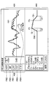
- FIG. 3 is a diagram showing an example of the PEQ editing screen.
- the PEQ editing screen is provided with three areas A01 and A03 and an icon area A02. Regions A01 and A03 each correspond to a two-dimensional plane in which one coordinate axis represents frequency and the other coordinate axis represents gain (or amplitude level).
- a total curve C01 of frequency responses obtained by synthesizing the frequency responses of the plurality of PEQ filter elements is displayed.
- a graph TR of the reproduction system frequency characteristics indicated by the measurement data is drawn so as to overlap the total curve C01.
- the user can grasp from the graph TR drawn in the region A01 the frequency band to be adjusted, such as lowering the gain by PEQ, the amount to be lowered, and the like.
- the area A03 an individual curve C02 of the frequency response of one filter element selected by the user from among the plurality of filter elements is displayed.
- the graph TR may be a graph in which the frequency characteristic of the reproduction system indicated by the measurement data is not vertically inverted (the level is higher toward the upper side of the vertical axis) (see the area A01 in FIG. 3), or a graph (vertical axis on the vertical axis) The level may be smaller as it goes up. Further, whether to draw a graph that is not flipped upside down or to draw a reversed graph may be switched according to a user operation.
- a plurality of icons respectively corresponding to a plurality of filter elements that can be used for adjusting the frequency characteristics of the reproduction system are displayed.
- five types of icons FI01 to FI05 are illustrated.
- Each of the icons FI01 to FI05 is associated with a class for the filter element indicated by each icon in advance.
- Each filter element class includes a plurality of parameters that define the frequency response of the filter element.
- the icon FI01 is an icon indicating a low-pass filter (LPF) element.
- the class corresponding to the icon FI01 includes three types of parameters representing the cutoff frequency Fh, gain Gh, and slope Sh of the LPF.
- the inclination Sh indicates the inclination level of the gain (inclination portion on the high frequency side) in the frequency section where the gain of the LPF element falls from the gain Gh to 0 dB.
- the inclination level is a parameter indicating the degree of inclination according to the width of the frequency section.
- the cut-off frequency Fh, the order Nh, and the quality factor Qh may be used as parameters of the LPF element instead of the cut-off frequency Fh, the gain Gh, and the slope Sh.
- the quality factor Qh is a parameter that represents the slope in the frequency response as a half-value width.
- Icon FI02 is an icon indicating a high-pass filter (HPF) element.
- the class corresponding to the icon FI02 includes three types of parameters representing the cutoff frequency Fl, gain Gl, and slope Sl of the HPF.
- Inclination Sl indicates the inclination level of the gain (inclination portion on the low frequency side) in a frequency section in which the gain of the HPF element rises from 0 decibel to gain Gl.
- the cut-off frequency Fl, the order Nl, and the quality factor Ql may be used instead of the cut-off frequency Fl and the gain Gl or Sl.
- the quality factor Ql is a parameter representing the slope in the frequency response as a half width.
- the icon FI03 is an icon indicating a flat type filter (FTF) element.
- the frequency response of the FTF element is divided into a lower inclined portion, a central flat portion, and an upper inclined portion on the frequency axis.
- the lower inclined portion is located on the low frequency side of the central flat portion.
- the upper inclined portion is located on the high frequency side of the central flat portion.
- the central flat portion is a portion where the gain is kept constant.
- the class corresponding to the icon FI03 includes five types of parameters representing the gain G, the lower frequency Fl, the lower slope Sl, the upper frequency Fh, and the upper slope Sh, respectively.
- the gain G is a gain at the central flat portion of the FTF element.
- the lower frequency Fl is a frequency corresponding to the boundary between the central flat portion and the lower inclined portion.
- the lower slope S1 is a parameter indicating the slope level of the lower slope portion.
- the upper frequency Fh is a frequency corresponding to the boundary between the central flat portion and the upper inclined portion.
- the upper inclination Sh is a parameter indicating the inclination level of the upper inclination portion.
- the icon FI04 is an icon indicating a tilt type filter (TTF: Tilt Type Filter) element.
- TTF tilt Type Filter
- the frequency response of the TTF element is divided into a lower inclined portion, a central inclined portion, and an upper inclined portion on the frequency axis.
- the lower inclined portion is located on the lower band side of the central inclined portion in a predetermined band on the frequency axis (hereinafter referred to as “predetermined band”).
- predetermined band a predetermined band on the frequency axis
- the upper inclined portion is located on the high frequency side of the central inclined portion within the predetermined band.
- the central inclined portion is a portion where the gain increases or decreases linearly as the frequency increases. That is, the TTF element is a filter element in which a central inclined portion is provided instead of the central flat portion in the FTF element.
- the central inclined portion has a substantially constant inclination.
- This TTF element has one of the features of this embodiment.
- the class corresponding to the icon FI04 includes six types of parameters representing the lower frequency Fl, the gain G1, the lower gradient Sl, the upper frequency Fh, the gain Gh, and the upper gradient Sh.
- the lower frequency Fl is a frequency corresponding to the boundary between the central inclined portion and the lower inclined portion.
- the gain Gl is a gain at the lower frequency Fl.
- the lower slope S1 is a parameter indicating the slope level of the lower slope portion.
- the upper frequency Fh is a frequency corresponding to the boundary between the central inclined portion and the upper inclined portion.
- the gain Gh is a gain at the upper frequency Fh.
- the gain Gl and the gain Gh can be different.
- the upper inclination Sh is a parameter indicating the inclination level of the upper inclination portion. In place of the slope Sh or Sl expressed by the frequency width, a quality factor Qh or Ql representing the
- Icon FI05 is an icon indicating a bell filter (BF) element.
- the bell filter is a filter whose frequency response is bell-shaped.
- the class corresponding to the icon F105 includes three parameters representing the center frequency Fc, the center gain Gc, and the quality factor Q of the band of the BF element.
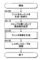
- FIG. 4 is a flowchart showing a filter control process executed by the CPU 110 in accordance with the filter control program when receiving operation data indicating icon drag and drop by the user.
- the operation data includes information indicating the drag and drop start position and end position.
- the CPU 110 receives the operation data, the CPU 110 generates an instance of the filter element based on the class of the filter element corresponding to the dragged and dropped icon, and initializes a parameter defining the frequency response of the filter element (step). SA100). More specifically, the CPU 110 identifies an icon at the start position indicated by the operation data, and newly generates a filter element from the class corresponding to the icon. For example, when the icon FI04 is dragged and dropped, the CP 110 generates an instance of the TTF element (TTF element), and sets six types of parameters that define the frequency response of the TTF element as initial values.
- TTF element TTF element
- step SA110 the CPU 110 sets the upper frequency Fh and the lower frequency Fl corresponding to the end position indicated by the operation data (that is, the icon drop position). For example, the CPU 110 sets a frequency higher by a predetermined frequency from the frequency corresponding to the drop position as the upper frequency Fh, and sets a frequency lower by a predetermined frequency than the frequency corresponding to the drop position as the lower frequency Fl.
- CPU 110 generates filter coefficients of the FIR filter from all parameters included in all types of set filter elements (including the TTF element) (step SA120).
- the CPU 110 draws the total curve C01 representing the frequency response of the FIR filter (PEQ) in the area A01 of the PEQ editing screen, and draws the individual curve C02 representing the frequency response of the TTF element alone in the area A03.
- the display unit 141 is controlled (step SA130). Note that the processing content of the filter coefficient generation processing executed by the CPU 110 in step SA120 will be described in detail later.
- the CPU 110 controls the display unit 141 to display the handle icon in the icon area A02 together with the individual curve C02 of the frequency response of the filter element.
- the handle icon is an operator that allows the user to change the value of a parameter that defines the frequency response. For example, when the user drags and drops the icon FI04 corresponding to the TTF element to the area A01, or when the TTF element portion of the total curve C01 displayed in the area A01 is selected by mouse click, As shown in FIG. 5, the CPU 110 controls the display unit 141 to display the individual curve C02 of the TTF element to which the handle icons H01 and H02 are added in the area A03.
- the handle icon H01 is disposed at a position corresponding to the boundary between the lower inclined portion and the central inclined portion.
- the handle icon H02 is disposed at a position corresponding to the boundary between the upper inclined portion and the central inclined portion.
- the CPU 110 changes a parameter corresponding to the operation among a plurality of parameters defining the frequency response of the TTF element. .
- the CPU 110 changes the lower frequency Fl.
- the CPU 110 changes the upper frequency Fh.
- the CPU 110 changes the lower gain Gl.
- the CPU 110 changes the upper gain Gh.
- FIG. 6 is a flowchart showing the flow of the filter coefficient changing process.
- CPU 110 generates a filter coefficient in accordance with the changed parameter (step SB100).
- CPU 110 updates the response curves (total curve C01 and individual curve C02) drawn on the PEQ editing screen (step SB110).
- the generation process executed by the CPU 110 in step SB100 is basically the same as the generation process in step SA120 described above, and details thereof will be clarified later.
- FIG. 7 is a flowchart showing the flow of the filter coefficient generation process executed in step SA120 of the filter control process or step SB100 of the filter coefficient change process.
- the CPU 110 accepts parameters of one or more filter elements that define the PEQ frequency response (step SC100).
- These filter elements correspond to one or a plurality of filter elements constituting the PEQ, that is, one or a plurality of filter elements sequentially arranged in the area A01 by the user's drag and drop operation.
- the CPU 110 creates response curves (total curve C01 and individual curve C02) representing frequency responses defined by the parameters received in step SC100.
- the response curve is represented by a straight line or a curve on a two-dimensional plane in which one coordinate axis represents frequency and the other coordinate axis represents gain.
- step SC110 CPU 110 first creates a frequency response curve of each filter element defined by the parameters of each filter element among the plurality of parameters received in step SC100, and further synthesizes the created curves. By doing so, the curve of the frequency response of the filter (PEQ) is created. For the filter elements other than the TTF element, the method of creating this curve is well known and will be omitted. On the other hand, the curve of the TTF element is created for each of the three portions of the curve as follows. (Creation process 1) A lower curve that changes from the gain Gl to the reference level (0 dB) in the frequency range (first range) of the width indicated by the lower slope Sl toward the direction in which the frequency decreases from the lower frequency Fl.
- the curve being continuous at the boundary means that both the value of the curve and its differential value are continuously changed across the boundary.
- the adjustment step is required because if the response curve of the filter element is not smooth at any frequency, an undesirable sharp phase change occurs at that frequency, and the negative effects of that phase change are perceived by the listener of the reproduced sound. Because it is done.
- the numerical value “ ⁇ 1” at the lower end of the cosine curve is adjusted to the reference gain at one end of the third range, and the numerical value “1” at the upper end is adjusted to the gain Gh at the other end of the third range.
- the upper curve and the central flat part curve are continuous.
- the TTF element there is no simple method of smoothly connecting the lower curve or the upper curve and the central curve at the boundary.
- the gain at the boundary is matched with the gain at the boundary of the central inclined portion using the cosine curve corresponding to the half wavelength as the lower curve or the upper curve as in the FTF element (simple connection)
- the cosine at the boundary is used.
- the slope (differential value) of the curve does not match the slope of the central slope.
- the gain of the cosine curve does not match the gain Gl or Gh of the central slope.
- the CPU 110 performs a slightly complicated curve adjustment in the adjustment step in order to make the lower inclined portion or the upper inclined portion and the central inclined portion continue in the vicinity of the boundary. For example, following the simple connection described above, the CPU 110 further deletes a predetermined range including the boundary of the connected curves, and performs a fourth-order or higher-order Lagrange interpolation on the curves in the deleted range. Generated by interpolation operation.
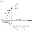
- the CPU 110 may execute the processing illustrated in FIG. 8 following the above-described simple connection. That is, the CPU 110 first causes the provisional lower curve GS (f) and the extended straight line GT (f) to intersect at the intersection point P1 and the intersection point P2.
- the provisional lower curve GS (f) is a cosine curve corresponding to a half wavelength whose upper end is located at the frequency Fl, for example.
- the extended straight line GT (f) is a tangent line of the upper curve or the central curve at the frequency Fh (that is, an extended line of the upper curve or the central curve). As shown in FIG. 8, the lower curve GS (f) and the extended straight line GT (f) intersect at the intersection P2 of the frequency Fl and the intersection P1 of the frequency f0 lower than the frequency Fl.
- the CPU 110 calculates a curve R (f) from the frequency f0 (f0 ⁇ Fl) at the intersection P1 to the frequency Fl at the intersection P2 by the following equation (1).
- the curve R (f) corresponds to a weighted sum of the lower curve GS (f) having the variable x (f) as a weight value and the extended straight line GT (f).
- the variable x (f) continuously decreases from 1 to 0 as the frequency increases from the frequency f0 to the frequency Fl.
- R (f) x (f) ⁇ GS (f) + (1 ⁇ x (f)) ⁇ GT (f) (1)
- two examples are shown, but the present invention is not limited to this, and other methods may be used. It is not essential to use a cosine curve for the lower curve or the upper curve, and other curves may be used.
- step SC120 CPU 110 estimates (generates) a filter coefficient that approximates the frequency response of filter 20 to the curve based on the response curve created in step SC110. Specifically, CPU 110 calculates an impulse response by performing inverse FFT on the response curve created in step SC110. Then, CPU 110 gives the impulse response calculated in step SC120 to SPU 160 as a filter coefficient (step SC130). When the SPU 160 performs convolution in the frequency domain, the CPU 110 may supply the response curve created in step SC110 as it is to the SPU 160 as a filter coefficient.
- the SPU 160 (filter 20) controls the frequency characteristics of the sound data by convolving the filter coefficient supplied from the CPU 110 with the sound data. That is, the SPU 160 processes sound data based on the response curve generated by the CPU 110.
- the slope of the frequency characteristic of the reproduction system can be easily adjusted to the target characteristic in a specific frequency band.
- the number of parameters set is larger than that of the FTF element by one parameter that defines the inclination of the inclined portion.
- the number of filter elements to be used can be reduced, so the number of parameter settings is reduced as a whole, and the adjustment work to the target characteristics in the PEQ is made easier than before. It can be done easily.
- the upper frequency Fh, the upper slope Sh, the upper gain Gh, the lower frequency Fl, the lower slope Sl, and the lower gain Gl are used as six types of parameters that define the frequency response of the TTF element. Although used, it is not necessarily limited to this.
- the frequency response of the TTF element may be defined using the upper frequency Fh, the upper gradient Sh, the lower frequency Fl, the lower gradient Sl, the central gain Gc, and the gradient T.
- the central gain Sc is a gain at a frequency intermediate between the upper frequency Fh and the lower frequency Fl.
- the inclination T is an angle formed by the central curve in the central inclined portion with respect to the coordinate axis (for example, gain axis).
- a first parameter for example, a center frequency of the specific band
- a second parameter that indicates the width of the specific band
- the upper frequency Fh can be calculated by adding the half value of the second parameter to the first parameter
- the lower frequency Fl is calculated by subtracting the half value of the second parameter from the first parameter.
- the upper slope Sh and the lower slope Sl are variable values, and each may be a fixed value determined in advance.
- the TTF element in a preferred aspect of the present invention is a filter in which the position and width of a specific band and the slope and gain of the central slope portion of the frequency response are controlled based on four parameters. The configuration of the parameters is arbitrary within the range.
- the FIR filter function for processing the sound signal according to the filter coefficient and the filter control function for supplying the filter coefficient to the filter according to the parameter set by the operation from the user are provided.
- the audio processing apparatus 1 is illustrated.
- the filter control device having the filter control function and the filter processing device having the filter function may be configured as two devices independent from each other.
- the audio processing device 1 (CPU 110) of the above-described embodiment is a plurality of parameters that define the frequency response, and is between a low-frequency side slope and a high-frequency side slope in a predetermined band.
- a response curve representing the frequency response of the filter is created on the frequency-gain plane based on the plurality of parameters.
- the filter element is a filter element that controls the frequency characteristics of the specific band of the sound signal. First, the position and width of the specific band are controlled based on the first and second parameters. This is a filter element in which the slope and gain of the frequency response in the specific band of the filter element are controlled based on the third and fourth parameters.
- the mode of the gain change in the lower slope part and the upper slope part is as follows. It is not limited to the above illustration. For example, assuming that the gain rises to the specified value Gl at the lower slope and the gain falls from the designated value Gl to the designated value Gh below the reference gain (0 decibel) at the central slope, the gain at the upper slope Increases from the specified value Gh to the reference gain.
- the gain in the section decreases from the specified value Gh to the reference gain. That is, the gain may change in the same direction (increase / decrease) in the lower inclined portion and the upper inclined portion.
- a program for causing a general computer to execute the filter control method of the present invention may be provided.
- a program for causing a general computer or a signal processor to function as the filter element of the present invention may be provided. Any program may be distributed by writing the program on a computer-readable recording medium or by downloading via a telecommunication line such as the Internet.
- the programs exemplified above can be provided in a form stored in a computer-readable recording medium and installed in the computer.
- the recording medium is, for example, a non-transitory recording medium, and an optical recording medium (optical disk) such as a CD-ROM is a good example, but a known arbitrary one such as a semiconductor recording medium or a magnetic recording medium This type of recording medium is also included.
- the non-transitory recording medium includes an arbitrary recording medium excluding a transient propagation signal (transitory, “propagating” signal), and does not exclude a volatile recording medium. Further, in a configuration in which a distribution device distributes a program via a communication network such as the Internet, the storage device that stores the program in the distribution device corresponds to the non-transitory recording medium.
- a filter control method includes a plurality of parameters that define a frequency response, a lower inclined portion whose gain changes on a low frequency side within a predetermined band, A response curve that represents the frequency response of the filter in response to the plurality of parameters including a specific parameter that defines a central slope where the gain changes between the upper slope where the gain changes on the high frequency side in the band;
- the filter coefficient is generated based on the plurality of parameters, and the filter coefficient of the filter is generated based on the response curve.
- the plurality of parameters are parameters of one filter element constituting the filter.
- the response curve in the creation of the response curve, is continuous at the boundary between the low-frequency side inclined portion and the central inclined portion, and the high The response curve is adjusted so that the response curve continues at the boundary between the region-side inclined portion and the central inclined portion.
- the specific parameter defines the inclination and gain of the central inclined portion.
- the specific parameter further defines the position and width of the central inclined portion on the frequency axis.
- An audio processing method is a plurality of parameters that define a frequency response, a lower inclined portion whose gain changes on a low frequency side within a predetermined band, A response curve that represents the frequency response of the filter in response to the plurality of parameters including a specific parameter that defines a central slope where the gain changes between the upper slope where the gain changes on the high frequency side in the band;
- the filter coefficient is generated based on the plurality of parameters, the filter coefficient of the filter is generated based on the response curve, and the filter coefficient is convolved with sound data by the filter.
- a filter control device includes one or more processors and a memory, and the plurality of processors that define a frequency response by the one or more processors executing a program stored in the memory.
- a central slope where the gain changes between a lower slope where the gain changes on the low frequency side within the predetermined band and an upper slope where the gain changes on the high frequency side within the predetermined band.
- a program according to one aspect of the present invention is a computer that includes a plurality of parameters that define a frequency response, a lower inclined portion whose gain changes on a low frequency side within a predetermined band, and a high frequency within the predetermined band.
- a process of receiving the plurality of parameters including a specific parameter that defines a central slope portion in which the gain changes between the upper slope portion in which the gain changes on the band side, and a response curve representing the frequency response of the filter,
- a process of creating based on a plurality of parameters and a process of generating a filter coefficient of the filter based on the response curve are executed.
- a filter element is a filter element that controls frequency characteristics of a specific band of a sound signal, and the position and width of the specific band are controlled based on first and second parameters. Based on the third and fourth parameters, the slope and gain of the frequency response in the specific band of the filter are controlled.
- SYMBOLS 1 Audio processing apparatus, 10 ... Analog / digital converter, 20 ... Filter, 30 ... Digital / analog converter, 40 ... Filter coefficient calculating part, 50 ... Setting part, 110 ... CPU, 120 ... Non-volatile memory, 130 ... Volatility Memory 140... User interface unit 150 150 External device interface unit 160 SPU 170 170 Bus
Landscapes
- Physics & Mathematics (AREA)
- Engineering & Computer Science (AREA)
- Acoustics & Sound (AREA)
- Signal Processing (AREA)
- Computer Hardware Design (AREA)
- Mathematical Physics (AREA)
- Tone Control, Compression And Expansion, Limiting Amplitude (AREA)
- Circuit For Audible Band Transducer (AREA)
- Filters That Use Time-Delay Elements (AREA)
Abstract
音信号の制御に使用されるフィルタエレメントの周波数レスポンスを規定する複数のパラメータであって、低域側の傾斜部と高域側の傾斜部との間の中央傾斜部を規定するパラメータを含む複数のパラメータを受け付け、一方の座標軸が周波数を表し、他方の座標軸が音量レベルを表す2次元平面においてフィルタエレメントの周波数レスポンスを表すレスポンスカーブを、複数のパラメータから作成し、フィルタに対し、その周波数レスポンスをレスポンスカーブに近づけるフィルタ係数を供給するフィルタ制御方法を提供する。
Description
本発明は、音データを処理するフィルタを制御する技術に関する。
コンサートホール等の音響空間へスピーカから放射される音を調整するために、イコライザ等の音響機器が利用される。イコライザは、周波数特性を調整するフィルタである。イコライザの一例としてパラメトリックイコライザ(PEQ)が挙げられる。PEQは、入力音信号の周波数特性を制御する複数のフィルタエレメントを含んでいる。音響技術者(ユーザ)は、各フィルタエレメントの帯域の中心周波数、帯域幅およびゲインといったパラメータの設定を通じて、上記イコライザのフィルタ係数を調整し、音響空間において放射される音の周波数特性(イコライザ、アンプ、スピーカ、および音響空間を含む再生系の周波数特性)を、目標特性に合わせ込むことができる(例えば、特許文献1:図16)。
近年では、目標特性への合わせ込み作業をより簡便に行えるようにするために、PEQのフィルタエレメントとして平坦型エレメントが提案されている。平坦型エレメントの周波数レスポンスは、低域側の傾斜部(下側傾斜部)および高域側の傾斜部(上側傾斜部)と、両傾斜部の間でゲインが一定のユーザ指定値である中央平坦部とを含む。下側傾斜部とは、周波数が上がるに連れて基準ゲイン(0デシベル)からその指定値へゲインが立ち上がる(または立ち下がる)区間の周波数レスポンスのことを言い、上側傾斜部とは、周波数が上がるに連れてその指定値から基準ゲイン(0デシベル)へ向けてゲインが立ち下がる(または立ち上がる)区間の周波数レスポンスのことを言う。平坦型エレメントの上側傾斜部および下側傾斜部は、それぞれ、コサイン曲線の形状を有する。
しかし、再生系の周波数特性によっては、平坦型エレメントを含む従来のPEQのフィルタエレメント群を用いたのでは簡便に合わせ込みできない場合がある。例えば、再生系の周波数特性が、ある周波数帯域で傾いている(例えば周波数が低いほど音量レベルが大きい)と、1つの平坦型エレメントではその周波数帯域を平坦な特性に制御できず、2以上のフィルタエレメントが必要になる。また、コンサートホール等の音響空間における音響調整では、低域から高域までの広い周波数帯域にわたる緩やかな周波数特性の傾き(例えば高域の距離減衰に応じた傾き)を是正したい場合があるが、従来の平坦型エレメントでは、そういった傾きの是正はできない。前者の比較的狭い周波数帯域に関しては、2つの平坦型エレメントを組み合わせて、周波数特性の傾きを平坦にすることは不可能ではないが、2つの平坦型エレメントの各々についてパラメータを個別に設定する必要がある。
本発明は以上に説明した課題に鑑みて為されたものであり、PEQにおいて、再生系の周波数特性を目標特性へ合わせ込む作業を、ユーザが簡便に行えるようにする技術を提供すること目的とする。
上記課題を解決するために、本発明のひとつの態様に係るフィルタ制御方法は、周波数レスポンスを規定する複数のパラメータであって、所定帯域内の低域側においてゲインが変化する下側傾斜部と、当該所定帯域内の高域側においてゲインが変化する上側傾斜部と、の間においてゲインが変化する中央傾斜部を規定する特定のパラメータを含む前記複数のパラメータを受け、周波数-ゲイン平面において、フィルタの周波数レスポンスを表すレスポンスカーブを、前記複数のパラメータに基づいて作成し、前記レスポンスカーブに基づき、前記フィルタのフィルタ係数を生成する。
本発明のひとつの態様に係るオーディオ処理方法は、周波数レスポンスを規定する複数のパラメータであって、所定帯域内の低域側においてゲインが変化する下側傾斜部と、当該所定帯域内の高域側においてゲインが変化する上側傾斜部と、の間においてゲインが変化する中央傾斜部を規定する特定のパラメータを含む前記複数のパラメータを受け、フィルタの周波数レスポンスを表すレスポンスカーブを、前記複数のパラメータに基づいて作成し、前記レスポンスカーブに基づき、前記フィルタのフィルタ係数を生成し、前記フィルタ係数を前記フィルタにより音データに畳み込む。
本発明のひとつの態様に係るフィルタ制御装置は、1以上のプロセッサとメモリとを具備するフィルタ制御装置であって、前記メモリに記憶されたプログラムを前記1以上のプロセッサが実行することにより、周波数レスポンスを規定する複数のパラメータであって、所定帯域内の低域側においてゲインが変化する下側傾斜部と、当該所定帯域内の高域側においてゲインが変化する上側傾斜部と、の間においてゲインが変化する中央傾斜部を規定する特定のパラメータを含む前記複数のパラメータを受け、フィルタの周波数レスポンスを表すレスポンスカーブを、前記複数のパラメータに基づいて作成し、前記レスポンスカーブに基づき、前記フィルタのフィルタ係数を生成する。
本発明のひとつの態様に係るプログラムは、コンピュータに、周波数レスポンスを規定する複数のパラメータであって、所定帯域内の低域側においてゲインが変化する下側傾斜部と、当該所定帯域内の高域側においてゲインが変化する上側傾斜部と、の間においてゲインが変化する中央傾斜部を規定する特定のパラメータを含む前記複数のパラメータを受け取る処理と、フィルタの周波数レスポンスを表すレスポンスカーブを、前記複数のパラメータに基づいて作成する処理と、前記レスポンスカーブに基づき、前記フィルタのフィルタ係数を生成する処理とを実行させる。
本発明のひとつの態様に係るフィルタエレメントは、音信号の特定帯域の周波数特性を制御するフィルタエレメントであって、第1および第2パラメータに基づいて、前記特定帯域の位置と幅とが制御され、第3および第4パラメータに基づいて、当該フィルタの前記特定帯域における周波数レスポンスの傾きとゲインとが制御される。
以下、図面を参照しつつ本発明の実施形態を説明する。
A:実施形態
図1は、本発明の一実施形態によるオーディオ処理装置1の機能ブロック図である。オーディオ処理装置1は、コンサートホール等の音響空間へスピーカから放射される音を調整するためのPEQである。図1に示すように、オーディオ処理装置1は、アナログ/デジタルコンバータ10、フィルタ20、デジタル/アナログコンバータ30、フィルタ係数演算部40、および設定部50を含む。なお、図1では、アナログ/デジタルコンバータ10は「ADC10」と表記されており、デジタル/アナログコンバータ30は「DAC30」と表記されている。
A:実施形態
図1は、本発明の一実施形態によるオーディオ処理装置1の機能ブロック図である。オーディオ処理装置1は、コンサートホール等の音響空間へスピーカから放射される音を調整するためのPEQである。図1に示すように、オーディオ処理装置1は、アナログ/デジタルコンバータ10、フィルタ20、デジタル/アナログコンバータ30、フィルタ係数演算部40、および設定部50を含む。なお、図1では、アナログ/デジタルコンバータ10は「ADC10」と表記されており、デジタル/アナログコンバータ30は「DAC30」と表記されている。
ADC10には、オーディオプレイヤ等の音源機器(図1では図示略)が接続され、DAC30には、上記音響空間内に設置されるスピーカ(図1では図示略)が接続される。なお、音源機器とADC10の間にアンプを接続しても良く、DAC30とスピーカの間にアンプを接続してもよい。ADC10は、マイクロホン、楽器またはレコーダ等の音源機器から入力されるアナログの入力音信号にアナログ/デジタル変換を施し、変換結果である音データをフィルタ20へ与える。フィルタ20は、ADC10から与えられた音データにフィルタ係数を畳み込んで音データの周波数特性を制御し、畳み込み後の音データをDAC30へ出力するFIR(Finite Impulse Response)型のフィルタである。DAC30は、フィルタ20からの音データをアナログの出力音信号に変換して上記スピーカへ出力する。設定部50は、フィルタ20の周波数レスポンスを規定する複数種のパラメータをユーザに設定させるためのユーザインタフェースを提供する。設定部50は、ユーザによるパラメータの編集操作に応じてパラメータの値を編集し、その編集されたパラメータをフィルタ係数演算部40に与える。フィルタ係数演算部40は、設定部50からのパラメータに応じたフィルタ係数を生成し、フィルタ20に与える。
図2は、オーディオ処理装置1のハードウェア構成の一例を示すブロック図である。図2に示すように、オーディオ処理装置1は、CPU(Central Processing Unit)110と、不揮発性メモリ120と、揮発性メモリ130と、ユーザインタフェース部140と、外部機器インタフェース部150と、フィルタ20として機能するSPU(Signal Processing Unit)160と、これら構成要素間のデータ授受を仲介するバス170と、を有する。なお、図2では、外部機器インタフェース部150は「外部機器I/F部150」と略記されている。
不揮発性メモリ120は例えばROM(Read Only Memory)であり、揮発性メモリ130は例えばRAM(Random Access Memory)である。不揮発性メモリ120には、本実施形態の特徴を示すフィルタ制御方法をCPU110に実行させるフィルタ制御プログラムが予め記憶されている。揮発性メモリ130は、フィルタ制御プログラムを実行する際のワークエリアとしてCPU110によって利用される。
CPU110は、プログラムを実行する1以上のプロセッサで構成される。CPU110は、不揮発性メモリ120に記憶されたフィルタ制御プログラムを実行することでフィルタ係数演算部40(図1参照)として機能する。SPU160は、入力音信号にA/D変換を施して得られる音データに対して、時間領域でFIRフィルタのフィルタ係数を畳み込むことで、音データの周波数特性を制御する。なお、SPU160の代わりに、CPU110がフィルタ係数の畳み込みを行ってもよい。その場合、SPU160を省略してよい。また、SPU160は、フィルタ係数の畳み込みを周波数領域で行うタイプであってもよい。その場合、SPU160は、時間領域の音データを例えばFFTにより周波数領域の音データに変換し、変換された音データにフィルタ係数を乗算する。SPU160は、乗算結果の音データに対する逆FFTにより時間領域の音データを得る。
外部機器I/F部150は、オーディオケーブル等の信号線を介して音源機器またはスピーカ等の外部機器をオーディオ処理装置1に接続するためのインタフェースの集合体である。図2に示すように、外部機器I/F部150は、ADC10とDAC30とを含む。外部機器I/F部150は、ADC10によるアナログ/デジタル変換を経た音データをバス170を介してSPU160に与え、SPU160から出力される音データをバス170を介して受け取り、DAC30に与える。
また、外部機器I/F部150は、オーディオ処理装置1による調整前の再生系で計測された周波数特性を表す計測データをオーディオ処理装置1に入力する。例えば、別の機器で予め計測した周波数特性の計測データを記憶したUSBメモリ等の記録媒体が外部機器I/F部150に接続され、オーディオ処理装置1は、当該記録媒体から再生系の計測データを読み出す。また、上記音響空間に設置されるマイクロホンおよびスピーカを外部機器I/F部150に接続し、オーディオ処理装置1が、自ら、そのスピーカから上記音響空間へテスト音(白色ノイズ等)を放射し、上記音響空間の音をマイクロホンにより収音して、当該収音された音から再生系の計測データを生成してもよい。
ユーザI/F部140は、液晶ディスプレイ等の表示部141と、マウスまたはキーボード等の操作部142とを含み、CPU110による制御の下、図1における設定部50として機能する。表示部141は、CPU110による制御の下、フィルタ20の周波数レスポンスを規定する複数種のパラメータの編集操作をユーザに促すPEQ編集画面(図3参照)の画像を表示する。ユーザは、このPEQ編集画面を視認しつつ、操作部142を操作することで上記複数種のパラメータを編集する。操作部142は、ユーザにより編集操作が為されると、その操作を示す操作データをバス170を介してCPU110に与える。これにより、上記編集操作がCPU110に伝達される。
以上がオーディオ処理装置1の構成である。
以上がオーディオ処理装置1の構成である。
次いで、オーディオ処理装置1の動作を説明する。
前述したように、オーディオ処理装置1の電源(図2では図示略)が投入されると、CPU110は、フィルタ制御プログラムを不揮発性メモリ120から揮発性メモリ130に読み出し、当該フィルタ制御プログラムの実行を開始する。フィルタ制御プログラムにしたがって作動しているCPU110は、再生系の周波数特性の計測データを受け取り、PEQ編集画面(図3参照)をユーザI/F部140の表示部141に表示させる。
前述したように、オーディオ処理装置1の電源(図2では図示略)が投入されると、CPU110は、フィルタ制御プログラムを不揮発性メモリ120から揮発性メモリ130に読み出し、当該フィルタ制御プログラムの実行を開始する。フィルタ制御プログラムにしたがって作動しているCPU110は、再生系の周波数特性の計測データを受け取り、PEQ編集画面(図3参照)をユーザI/F部140の表示部141に表示させる。
図3は、PEQ編集画面の一例を示す図である。図3に示すようにPEQ編集画面には、領域A01およびA03とアイコン領域A02の3つの領域が設けられている。領域A01およびA03は、各々、一方の座標軸が周波数を表し、他方の座標軸がゲイン(又は振幅レベル)を表す2次元平面に対応する。領域A01には、PEQの複数のフィルタエレメントの周波数レスポンスを合成した周波数レスポンスのトータルカーブC01が表示される。さらに、領域A01には、計測データが示す再生系の周波数特性のグラフTRが、そのトータルカーブC01に重ねて描画される。ユーザは、領域A01に描画されたグラフTRから、PEQによりゲインを引き下げる等の調整を施すべき周波数帯域およびその引き下げるべき量等を把握できる。領域A03には、それら複数のフィルタエレメントの中からユーザにより選択された1個のフィルタエレメントの周波数レスポンスの個別カーブC02が表示される。
グラフTRは、計測データが示す再生系の周波数特性を上下反転してないグラフ(縦軸の上方ほどレベル大)でも良く(図3の領域A01参照)、または、上下反転したグラフ(縦軸の上方ほどレベル小)であってもよい。また、上下反転しないグラフを描画するのか、反転させたグラフ描画するのかをユーザの操作に応じて切り換えてもよい。
アイコン領域A02には、再生系の周波数特性の調整に使用可能な複数のフィルタエレメントにそれぞれ対応した複数のアイコンが表示される。図3に示す例では、5種類のアイコンFI01~FI05が例示されている。アイコンFI01~FI05の各々には、各アイコンが示すフィルタエレメントについてのクラスが予め対応付けられている。各フィルタエレメントのクラスには、そのフィルタエレメントの周波数レスポンスを規定する複数のパラメータが含まれる。
例えば、アイコンFI01はローパスフィルタ(LPF)エレメントを示すアイコンである。アイコンFI01に対応するクラスには、当該LPFのカットオフ周波数FhとゲインGhと傾斜Shとをそれぞれ表す3種類のパラメータが含まれる。傾斜Shは、LPFエレメントのゲインがゲインGhから0デシベルに立ち下がる周波数区間における当該ゲイン(高域側の傾斜部)の傾斜レベルを示す。傾斜レベルは、その周波数区間の幅によりその傾きの程度を示すパラメータである。なお、LPFエレメントのパラメータとして、カットオフ周波数Fh、ゲインGhおよび傾斜Shの代わりに、カットオフ周波数Fhと次数NhとクォリティファクタQhとを用いてもよい。クォリティファクタQhは、周波数レスポンスにおける傾斜を半値幅で表すパラメータである。
アイコンFI02はハイパスフィルタ(HPF)エレメントを示すアイコンである。アイコンFI02に対応するクラスには、当該HPFのカットオフ周波数FlとゲインGlと傾斜Slとをそれぞれ表す3種類のパラメータが含まれる。傾斜Slは、HPFエレメントのゲインが0デシベルからゲインGlに立ち上がる周波数区間における当該ゲイン(低域側の傾斜部)の傾斜レベルを示す。なお、HPFエレメントのパラメータとして、カットオフ周波数Fl、ゲインGlまたはSlの代わりに、カットオフ周波数Flと次数NlとクォリティファクタQlを用いてもよい。クォリティファクタQlは、周波数レスポンスにおける傾斜を半値幅で表すパラメータである。
アイコンFI03は平坦型フィルタ(FTF:Flat Type Filter)エレメントを示すアイコンである。FTFエレメントの周波数レスポンスは、周波数軸上で下側傾斜部と中央平坦部と上側傾斜部とに区分される。下側傾斜部は、中央平坦部の低域側に位置する。上側傾斜部は、中央平坦部の高域側に位置する。中央平坦部は、ゲインが一定に維持される部分である。アイコンFI03に対応するクラスには、ゲインGと下側周波数Flと下側傾斜Slと上側周波数Fhと上側傾斜Shとをそれぞれ表す5種類のパラメータが含まれる。ゲインGは、FTFエレメントにおける中央平坦部におけるゲインである。下側周波数Flは、中央平坦部と下側傾斜部との境界に対応する周波数である。下側傾斜Slは、当該下側傾斜部の傾斜レベルを示すパラメータである。上側周波数Fhは、中央平坦部と上側傾斜部との境界に対応する周波数である。上側傾斜Shは、当該上側傾斜部の傾斜レベルを示すパラメータである。
アイコンFI04は傾斜型フィルタ(TTF:Tilt Type Filter)エレメントを示すアイコンである。TTFエレメントの周波数レスポンスは、周波数軸上で下側傾斜部と中央傾斜部と上側傾斜部とに区分される。下側傾斜部は、周波数軸上の所定の帯域(以下「所定帯域」という)内における中央傾斜部の低域側に位置する。上側傾斜部は、所定帯域内における中央傾斜部の高域側に位置する。中央傾斜部は、周波数が高くなるに連れてゲインが直線的に増加または減少する部分である。すなわち、TTFエレメントは、FTFエレメントにおける中央平坦部に代えて中央傾斜部を設けたフィルタエレメントである。中央傾斜部はその傾きがほぼ一定である。このTTFエレメントに本実施形態の特徴の1つがある。アイコンFI04に対応するクラスには、下側周波数FlとゲインGlと下側傾斜Slと上側周波数FhとゲインGhと上側傾斜Shとをそれぞれ表す6種類のパラメータが含まれる。下側周波数Flは、中央傾斜部と下側傾斜部との境界に対応する周波数である。ゲインGlは、当該下側周波数Flにおけるゲインである。下側傾斜Slは、当該下側傾斜部の傾斜レベルを示すパラメータである。上側周波数Fhは、中央傾斜部と上側傾斜部との境界に対応する周波数である。ゲインGhは、当該上側周波数Fhにおけるゲインである。ゲインGlとゲインGhとは相違し得る。上側傾斜Shは、当該上側傾斜部の傾斜レベルを示すパラメータである。なお、周波数幅で表現される傾斜ShまたはSlの代わりに、半値幅で傾斜を表すクォリティファクタQhまたはQlを用いてもよい。
アイコンFI05はベルフィルタ(BF)エレメントを示すアイコンである。なお、ベルフィルタは、周波数レスポンスがベル状のフィルタである。アイコンF105に対応するクラスには、当該BFエレメントのバンドの中央周波数Fcと中央ゲインGcとクォリティファクタQとをそれぞれ表す3個のパラメータが含まれる。
ユーザは、アイコン領域A02に表示されている複数のアイコンのうち、再生系の周波数特性の調整に使用する所望のフィルタエレメントに対応するアイコンを、操作部142により選択する。ユーザは、選択したアイコンを、領域A01の周波数軸上において当該フィルタエレメントにより処理される所望の周波数帯域に対応する位置にドラッグ&ドロップする。図4は、ユーザによるアイコンのドラッグ&ドロップを示す操作データを受け取ったとき、CPU110がフィルタ制御プログラムにしたがって実行するフィルタ制御処理を示すフローチャートである。上記操作データには、ドラッグ&ドロップの開始位置および終了位置を表す情報が含まれる。
上記操作データを受け取ったCPU110は、ドラッグ&ドロップされたアイコンに対応するフィルタエレメントのクラスに基づき、そのフィルタエレメントのインスタンスを生成し、当該フィルタエレメントの周波数レスポンスを規定するパラメータを初期化する(ステップSA100)。より詳細に説明すると、CPU110は、操作データが示す開始位置にあるアイコンを特定し、当該アイコンに対応するクラスからフィルタエレメントを新たに生成する。例えば、アイコンFI04がドラッグ&ドロップされた場合には、CP110はTTFエレメントのインスタンス(TTFエレメント)を生成し、TTFエレメントの周波数レスポンスを規定する6種類のパラメータを初期値に設定する。以下、アイコンFI04がドラッグ&ドロップされた場合を例にとってCPU110の動作を説明する。
ステップSA100に後続するステップSA110では、CPU110は、操作データが示す終了位置(すなわち、アイコンのドロップ位置)に対応させて上側周波数Fhおよび下側周波数Flを設定する。例えば、CPU110は、上記ドロップ位置に対応する周波数から所定周波数分だけ高い周波数を上側周波数Fhに設定し、上記ドロップ位置に対応する周波数から所定周波数分だけ低い周波数を下側周波数Flに設定する。次に、CPU110は、設定済の全種類のフィルタエレメント(当該TTFエレメントを含む)に含まれる全部のパラメータからFIRフィルタのフィルタ係数を生成する(ステップSA120)。そして、CPU110は、FIRフィルタ(PEQ)の周波数レスポンスを表すトータルカーブC01を、PEQ編集画面の領域A01に描画するとともに、当該TTFエレメント単体の周波数レスポンスを表す個別カーブC02を領域A03に描画するよう表示部141を制御する(ステップSA130)。なお、ステップSA120においてCPU110が実行するフィルタ係数生成処理の処理内容については後に詳細に説明する。
ステップSA130では、CPU110は、フィルタエレメントの周波数レスポンスの個別カーブC02とともにハンドルアイコンをアイコン領域A02に表示するよう表示部141を制御する。ハンドルアイコンは、周波数レスポンスを規定するパラメータの値をユーザに変更させるための操作子である。例えば、TTFエレメントに対応するアイコンFI04をユーザが領域A01にドラッグ&ドロップした場合、または、領域A01に表示されたトータルカーブC01のうち、TTFエレメントの部分がマウスクリックで選択された場合には、CPU110は、図5に示すように、ハンドルアイコンH01およびH02が付加されたTTFエレメントの個別カーブC02を領域A03に表示するように表示部141を制御する。ハンドルアイコンH01は、下側傾斜部と中央傾斜部との境界に対応する位置に配置される。ハンドルアイコンH02は、上側傾斜部と中央傾斜部との境界に対応する位置に配置される。
ユーザが、ハンドルアイコンH01またはH02をマウス等の操作部142により上下左右に移動(ドラッグ)すると、CPU110は、TTFエレメントの周波数レスポンスを規定する複数のパラメータのうち当該操作に対応するパラメータを変更する。例えば、ユーザがハンドルアイコンH01を左右方向(周波数軸方向)に移動すると、CPU110は下側周波数Flを変更する。ユーザがハンドルアイコンH02を左右方向に移動すると、CPU110は、上側周波数Fhを変更する。また、ユーザがハンドルアイコンH01を上下方向(ゲイン軸方向)に移動するとCPU110は下側ゲインGlを変更し、ユーザがハンドルアイコンH02を上下方向に移動するとCPU110は上側ゲインGhを変更する。なお、ハンドルアイコンH01またはH02の左右方向の移動操作と上下方向の移動操作の各々を回転ノブまたはスライダ等の操作子で行うようにしてもよい。
ユーザが操作部142を用いて、或るフィルタエレメントの或るハンドルアイコンを移動する操作をすると、そのユーザ操作を示す操作データがCPU110に伝達される。CPU110は、当該操作データにしたがって、そのフィルタエレメントのハンドルアイコンに対応するパラメータの値を変更する。そして、CPU110は、何れかのパラメータの値の変更を契機としてフィルタ係数変更処理を実行する。図6は、フィルタ係数変更処理の流れを示すフローチャートである。図6に示すように、CPU110は、変更されたパラメータに応じてフィルタ係数を生成する(ステップSB100)。そして、CPU110は、PEQ編集画面に描画されたレスポンスカーブ(トータルカーブC01および個別カーブC02)を更新する(ステップSB110)。このステップSB100においてCPU110が実行する生成処理は、前述のステップSA120における生成処理と基本的に同一であり、その詳細については後に明らかにする。
図7は、フィルタ制御処理のステップSA120またはフィルタ係数変更処理のステップSB100にて実行されるフィルタ係数生成処理の流れを示すフローチャートである。
このフィルタ係数生成処理では、CPU110は、PEQの周波数レスポンスを規定する1または複数のフィルタエレメントのパラメータを受け付ける(ステップSC100)。これらフィルタエレメントは、PEQを構成する1または複数のフィルタエレメント、すなわち、ユーザのドラッグ&ドロップ操作により領域A01に順次配置された1または複数のフィルタエレメントに対応する。
次のステップSC110では、CPU110は、ステップSC100にて受け付けたパラメータにより規定される周波数レスポンスを表すレスポンスカーブ(トータルカーブC01および個別カーブC02)を作成する。レスポンスカーブは、一方の座標軸が周波数を表し、他方の座標軸がゲインを表す2次元平面における直線または曲線で表現される。
ステップSC110では、CPU110は、まず、ステップSC100にて受け付けた複数のパラメータのうちの各フィルタエレメントのパラメータにより規定される各フィルタエレメントの周波数レスポンスのカーブを作成し、さらに、作成されたカーブを合成することにより、フィルタ(PEQ)の周波数レスポンスのカーブを作成する。TTFエレメント以外のフィルタエレメントについては、このカーブの作成方法は公知であり省略する。一方、TTFエレメントのカーブは、以下のように、カーブの3つの各部分毎に作成される。
(作成処理1)下側周波数Flから周波数が低下する方向に向けて、下側傾斜Slが示す幅の周波数範囲(第1範囲)で、ゲインGlから基準レベル(0dB)に変化する下側カーブを作成する。
(作成処理2)下側周波数Flから上側周波数Fhの周波数範囲(第2範囲)で、ゲインGlからゲインGhに直線的に変化する中央カーブを作成する。なお、ゲインGlからゲインGhへの変化は直線的ではあるが、調整ステップでの調整により曲線となる場合もあるので、ここでは「カーブ」と呼ぶ。
(作成処理3)上側周波数Fhから周波数が上昇する方向に向けて、上側傾斜Shが示す幅の周波数範囲(第3範囲)で、ゲインGhから基準レベル(0dB)に変化する上側カーブを作成する。
これら作成処理1~作成処理3は、何れの順番に行ってもよい。
(作成処理1)下側周波数Flから周波数が低下する方向に向けて、下側傾斜Slが示す幅の周波数範囲(第1範囲)で、ゲインGlから基準レベル(0dB)に変化する下側カーブを作成する。
(作成処理2)下側周波数Flから上側周波数Fhの周波数範囲(第2範囲)で、ゲインGlからゲインGhに直線的に変化する中央カーブを作成する。なお、ゲインGlからゲインGhへの変化は直線的ではあるが、調整ステップでの調整により曲線となる場合もあるので、ここでは「カーブ」と呼ぶ。
(作成処理3)上側周波数Fhから周波数が上昇する方向に向けて、上側傾斜Shが示す幅の周波数範囲(第3範囲)で、ゲインGhから基準レベル(0dB)に変化する上側カーブを作成する。
これら作成処理1~作成処理3は、何れの順番に行ってもよい。
作成処理1~作成処理3の処理には、下側傾斜部または上側傾斜部と中央傾斜部との間の境界においてカーブが連続する(すなわち滑らかにつながる)ように、カーブ形状を調整する調整ステップが含まれる。境界においてカーブが連続するとは、当該境界を挟んでカーブの値とその微分値とが共に連続的に変化していることをいう。調整ステップが必要とされるのは、何れかの周波数においてフィルタエレメントのレスポンスカーブが滑らかでないと、当該周波数において望ましくない鋭い位相変化が発生し、その位相変化による悪影響が再生音の受聴者に知覚されるからである。
従来のFTFエレメントの場合、下側傾斜部または上側傾斜部と中央平坦部との境界において両者を連続させることはあまり難しくない。例えば、「-1」から「1」まで変化する半波長分のコサイン曲線を用意し、その下端の数値「-1」を第1範囲の一端で基準ゲインに合わせ、その上端の数値「1」を第1範囲の他端(境界)でゲインGlに合わせるだけで、下側カーブと中央平坦部のカーブとが連続する。上側傾斜部についても同様に、コサイン曲線の下端の数値「-1」を第3範囲の一端で基準ゲインに合わせ、その上端の数値「1」を第3範囲の他端でゲインGhに合わせるだけで、上側カーブと中央平坦部のカーブとが連続する。
これに対して、TTFエレメントでは、下側カーブまたは上側カーブと中央カーブとを、その境界において滑らかにつなぐ簡易な方法がない。例えば、FTFエレメントと同様に半波長分のコサイン曲線を下側カーブまたは上側カーブとして用いて、その上記境界におけるゲインを中央傾斜部の当該境界におけるゲインに合わせると(単純接続)、当該境界におけるコサイン曲線の傾き(微分値)は中央傾斜部の傾きと一致しない。逆に、コサイン曲線において傾きが中央傾斜部の傾きと一致する部分では、コサイン曲線のゲインが中央傾斜部のゲインGlまたはGhとは一致しない。
そこで、本実施形態では、下側傾斜部または上側傾斜部と中央傾斜部とを境界近傍で連続させるため、CPU110は、調整ステップにおいて、やや複雑なカーブの調整を行う。例えば、CPU110は、前述の単純接続に続けて、さらに、その接続されたカーブのうちその境界を含む所定の範囲を削除し、その削除された範囲内のカーブを4次以上のラグランジェ補間等の補間演算で生成する。
また、CPU110は、前述の単純接続に続けて、図8に例示する処理を実行してもよい。すなわち、CPU110は、まず、暫定的な下側カーブGS(f)と延長直線GT(f)とを、交点P1および交点P2において交差させる。暫定的な下側カーブGS(f)は、例えば周波数Flに上端が位置する半波長分のコサイン曲線である。また、延長直線GT(f)は、周波数Fhにおける上側カーブまたは中央カーブの接線(すなわち、上側カーブまたは中央カーブの延長線)である。図8に示すように、下側カーブGS(f)と延長直線GT(f)とは、周波数Flの交点P2と、当該周波数Flよりも低い周波数f0の交点P1とにおいて交差する。
CPU110は、交点P1の周波数f0(f0<Fl)から交点P2の周波数FlまでのカーブR(f)を、以下の式(1)により算出する。式(1)から理解される通り、カーブR(f)は、変数x(f)を加重値とする下側カーブGS(f)と延長直線GT(f)との加重和に相当する。変数x(f)は、周波数f0から周波数Flにかけて周波数の増加とともに1から0まで連続的に小さくなる。周波数f0から周波数Flまでの範囲内にカーブR(f)を用いることにより、下側カーブと中央カーブとが連続する。上側カーブについても、同様の方法を用いてよい。
R(f)=x(f)×GS(f)+(1-x(f))×GT(f)・・・(1)
なお、本実施形態では2つの例を示したが、これに限らず他の手法を用いてもよい。下側カーブまたは上側カーブにコサイン曲線を用いることも必須ではなく、他の曲線を用いてよい。
R(f)=x(f)×GS(f)+(1-x(f))×GT(f)・・・(1)
なお、本実施形態では2つの例を示したが、これに限らず他の手法を用いてもよい。下側カーブまたは上側カーブにコサイン曲線を用いることも必須ではなく、他の曲線を用いてよい。
ステップSC110に後続するステップSC120では、CPU110は、ステップSC110にて作成したレスポンスカーブに基づいて、フィルタ20の周波数レスポンスをそのカーブに近似させるフィルタ係数を推定(生成)する。具体的には、CPU110は、ステップSC110にて作成したレスポンスカーブに対する逆FFTを実行することで、インパルス応答を算出する。そして、CPU110は、ステップSC120にて算出したインパルス応答をフィルタ係数としてSPU160に与える(ステップSC130)。なお、SPU160が周波数領域で畳み込みを行う場合には、CPU110は、ステップSC110において作成したレスポンスカーブをフィルタ係数としてそのままSPU160に供給すればよい。SPU160(フィルタ20)は、CPU110から供給されたフィルタ係数を音データに畳み込むことで、音データの周波数特性を制御する。すなわち、SPU160は、CPU110が生成したレスポンスカーブに基づいて音データを処理する。
本実施形態のオーディオ処理装置1によれば、再生系の周波数特性の傾きを特定の周波数帯域において簡便に目標特性へ合わせ込むことができる。本実施形態のTTFエレメントでは、傾斜部の傾きを規定する1種類のパラメータの分だけFTFエレメントに比較してパラメータの設定数が多い。しかし、本実施形態のオーディオ処理装置1によれば、1つのTTFエレメントで、再生系の周波数特性の傾きを効果的に是正できる。従来のFTFエレメントを用いて是正する態様に比較して、使用するフィルタエレメントを減らせるので、全体としてパラメータの設定数が減少し、PEQにおける目標特性への合わせ込み作業を、ユーザが従来よりも簡便に行える。
B:変形例
以上、本発明の一実施形態について説明したが、この実施形態に以下の変形を加えてもよい。
以上、本発明の一実施形態について説明したが、この実施形態に以下の変形を加えてもよい。
(1)上記実施形態では、TTFエレメントの周波数レスポンスを規定する6種類のパラメータとして、上側周波数Fh、上側傾斜Sh、上側ゲインGh、下側周波数Fl、下側傾斜Sl、および下側ゲインGlを用いたが、これに限定される訳ではない。例えば、図9に示すように、上側周波数Fh、上側傾斜Sh、下側周波数Fl、下側傾斜Sl、中央ゲインGc、および傾斜Tを用いて、TTFエレメントの周波数レスポンスを規定してもよい。中央ゲインScは、上側周波数Fhと下側周波数Flの中間の周波数におけるゲインである。傾斜Tは、中央傾斜部における中央カーブが座標軸(例えばゲイン軸)に対してなす角度である。
また、上側周波数Fhおよび下側周波数Flに代えて、特定帯域の位置を指定する第1パラメータ(例えば特定帯域の中心周波数)と当該特定帯域の幅を示す第2パラメータとを用いてもよい。第1パラメータに第2パラメータの半分の値を加算することで上側周波数Fhを算出することができ、第1パラメータから第2パラメータの半分の値を減算することで下側周波数Flを算出することができる。また、上側傾斜Shおよび下側傾斜Slを可変値とすることは必須ではなく、それぞれ予め定めた固定値としてもよい。本発明の好適な態様におけるTTFエレメントは、4個のパラメータに基づいて、特定帯域の位置および幅と、周波数レスポンスの中央傾斜部の傾きおよびゲインとが制御されるフィルタであり、それら4種類のパラメータの構成はその範囲で任意である。
(2)前述の実施形態では、フィルタ係数に従って音信号を処理するFIRフィルタ機能と、ユーザからの操作により設定されたパラメータに応じてフィルタ係数をフィルタに供給するフィルタ制御機能とを具備する単体のオーディオ処理装置1を例示した。しかし、フィルタ制御機能を備えるフィルタ制御装置と、フィルタ機能を備えるフィルタ処理装置とを、相互に独立した2台の装置として構成してもよい。
フィルタ制御機能に関し、上記実施形態のオーディオ処理装置1(CPU110)は、周波数レスポンスを規定する複数のパラメータであって、所定帯域における低域側の傾斜部と高域側の傾斜部との間の中央傾斜部を規定する特定のパラメータを含む複数のパラメータを受け、周波数-ゲイン平面において、フィルタの周波数レスポンスを表すレスポンスカーブを、複数のパラメータに基づいて作成する。
なお、上記フィルタエレメントは、音信号の特定帯域の周波数特性を制御するフィルタエレメントであって、まず、第1および第2パラメータに基づいて、特定帯域の位置と幅とが制御され、さらに、第3および第4パラメータに基づいて、当該フィルタエレメントの特定帯域における周波数レスポンスの傾きとゲインとが制御されるフィルタエレメントである。
(3)前述の実施形態では、下側傾斜部と上側傾斜部とでゲインの変化の方向が反対である場合を例示したが、下側傾斜部および上側傾斜部とにおけるゲインの変化の態様は以上の例示に限定されない。例えば、下側傾斜部においてゲインが指定値Glまで上昇し、中央傾斜部においてゲインが指定値Glから基準ゲイン(0デシベル)を下回る指定値Ghまで低下する場合を想定すると、上側傾斜部におけるゲインは、指定値Ghから基準ゲインまで上昇する。同様に、下側傾斜部に置いてゲインが指定値Glまで低下し、中央傾斜部においてゲインが指定値Glから基準ゲイン(0デシベル)を上回る指定値Ghまで上昇する場合を想定すると、上側傾斜部におけるゲインは、指定値Ghから基準ゲインまで低下する。すなわち、下側傾斜部と上側傾斜部とにおいてゲインが同じ方向(上昇/低下)に変化してもよい。
(4)また、一般的なコンピュータに、本発明のフィルタ制御方法を実行させるプログラムを提供してもよい。
同様に、一般的なコンピュータまたは信号処理プロセッサを本発明のフィルタエレメントとして機能させるプログラムを提供してもよい。なお、何れのプログラムについても、コンピュータ読み取り可能な記録媒体にそのプログラムを書き込んで配布し、または、インターネット等の電気通信回線を経由したダウンロードにより配布すればよい。
以上に例示したプログラムは、コンピュータが読取可能な記録媒体に格納された形態で提供されてコンピュータにインストールされ得る。記録媒体は、例えば非一過性(non-transitory)の記録媒体であり、CD-ROM等の光学式記録媒体(光ディスク)が好例であるが、半導体記録媒体または磁気記録媒体等の公知の任意の形式の記録媒体も包含される。なお、非一過性の記録媒体とは、一過性の伝搬信号(transitory, propagating signal)を除く任意の記録媒体を含み、揮発性の記録媒体も除外されない。また、例えばインターネット等の通信網を介して配信装置がプログラムを配信する構成では、当該配信装置においてプログラムを記憶する記憶装置が、前述の非一過性の記録媒体に相当する。
<付記>
本発明のひとつの態様(第1態様)に係るフィルタ制御方法は、周波数レスポンスを規定する複数のパラメータであって、所定帯域内の低域側においてゲインが変化する下側傾斜部と、当該所定帯域内の高域側においてゲインが変化する上側傾斜部と、の間においてゲインが変化する中央傾斜部を規定する特定のパラメータを含む前記複数のパラメータを受け、フィルタの周波数レスポンスを表すレスポンスカーブを、前記複数のパラメータに基づいて作成し、前記レスポンスカーブに基づき、前記フィルタのフィルタ係数を生成する。
本発明のひとつの態様(第1態様)に係るフィルタ制御方法は、周波数レスポンスを規定する複数のパラメータであって、所定帯域内の低域側においてゲインが変化する下側傾斜部と、当該所定帯域内の高域側においてゲインが変化する上側傾斜部と、の間においてゲインが変化する中央傾斜部を規定する特定のパラメータを含む前記複数のパラメータを受け、フィルタの周波数レスポンスを表すレスポンスカーブを、前記複数のパラメータに基づいて作成し、前記レスポンスカーブに基づき、前記フィルタのフィルタ係数を生成する。
第1態様の一例(第2態様)において、前記複数のパラメータは、前記フィルタを構成する1つのフィルタエレメントのパラメータである。
第1態様または第2態様の一例(第3態様)において、前記レスポンスカーブの作成においては、前記低域側の傾斜部と前記中央傾斜部との境界において前記レスポンスカーブが連続し、かつ前記高域側の傾斜部と前記中央傾斜部との境界において前記レスポンスカーブが連続するように、前記レスポンスカーブを調整する。
第1態様から第3態様の何れかの一例(第4態様)において、前記特定のパラメータは、前記中央傾斜部の傾きとゲインとを規定する。
第4態様の一例(第5態様)において、前記特定のパラメータは、さらに、周波数軸における前記中央傾斜部の位置と幅とを規定する。
本発明のひとつの態様(第6態様)に係るオーディオ処理方法は、周波数レスポンスを規定する複数のパラメータであって、所定帯域内の低域側においてゲインが変化する下側傾斜部と、当該所定帯域内の高域側においてゲインが変化する上側傾斜部と、の間においてゲインが変化する中央傾斜部を規定する特定のパラメータを含む前記複数のパラメータを受け、フィルタの周波数レスポンスを表すレスポンスカーブを、前記複数のパラメータに基づいて作成し、前記レスポンスカーブに基づき、前記フィルタのフィルタ係数を生成し、前記フィルタ係数を前記フィルタにより音データに畳み込む。
本発明のひとつの態様に係るフィルタ制御装置は、1以上のプロセッサとメモリとを具備し、前記メモリに記憶されたプログラムを前記1以上のプロセッサが実行することにより、周波数レスポンスを規定する複数のパラメータであって、所定帯域内の低域側においてゲインが変化する下側傾斜部と、当該所定帯域内の高域側においてゲインが変化する上側傾斜部と、の間においてゲインが変化する中央傾斜部を規定する特定のパラメータを含む前記複数のパラメータを受け、フィルタの周波数レスポンスを表すレスポンスカーブを、前記複数のパラメータに基づいて作成し、前記レスポンスカーブに基づき、前記フィルタのフィルタ係数を生成する。
本発明のひとつの態様に係るプログラムは、コンピュータに、周波数レスポンスを規定する複数のパラメータであって、所定帯域内の低域側においてゲインが変化する下側傾斜部と、当該所定帯域内の高域側においてゲインが変化する上側傾斜部と、の間においてゲインが変化する中央傾斜部を規定する特定のパラメータを含む前記複数のパラメータを受け取る処理と、フィルタの周波数レスポンスを表すレスポンスカーブを、前記複数のパラメータに基づいて作成する処理と、前記レスポンスカーブに基づき、前記フィルタのフィルタ係数を生成する処理とを実行させる。
本発明のひとつの態様に係るフィルタエレメントは、音信号の特定帯域の周波数特性を制御するフィルタエレメントであって、第1および第2パラメータに基づいて、前記特定帯域の位置と幅とが制御され、第3および第4パラメータに基づいて、当該フィルタの前記特定帯域における周波数レスポンスの傾きとゲインとが制御される。
1…オーディオ処理装置、10…アナログ/デジタルコンバータ、20…フィルタ、30…デジタル/アナログコンバータ、40…フィルタ係数演算部、50…設定部、110…CPU、120…不揮発性メモリ、130…揮発性メモリ、140…ユーザインタフェース部、150…外部機器インタフェース部、160…SPU、170…バス。
Claims (9)
- 周波数レスポンスを規定する複数のパラメータであって、所定帯域内の低域側においてゲインが変化する下側傾斜部と、当該所定帯域内の高域側においてゲインが変化する上側傾斜部と、の間においてゲインが変化する中央傾斜部を規定する特定のパラメータを含む前記複数のパラメータを受け、
フィルタの周波数レスポンスを表すレスポンスカーブを、前記複数のパラメータに基づいて作成し、
前記レスポンスカーブに基づき、前記フィルタのフィルタ係数を生成する、
コンピュータにより実現されるフィルタ制御方法。 - 前記複数のパラメータは、前記フィルタを構成する1つのフィルタエレメントのパラメータである、
請求項1に記載のフィルタ制御方法。 - 前記レスポンスカーブの作成においては、前記低域側の傾斜部と前記中央傾斜部との境界において前記レスポンスカーブが連続し、かつ前記高域側の傾斜部と前記中央傾斜部との境界において前記レスポンスカーブが連続するように、前記レスポンスカーブを調整する
請求項1または2に記載のフィルタ制御方法。 - 前記特定のパラメータは、前記中央傾斜部の傾きとゲインとを規定する
請求項1~3の何れか1項に記載のフィルタ制御方法。 - 前記特定のパラメータは、さらに、周波数軸における前記中央傾斜部の位置と幅とを規定する
請求項4に記載のフィルタ制御方法。 - 周波数レスポンスを規定する複数のパラメータであって、所定帯域内の低域側においてゲインが変化する下側傾斜部と、当該所定帯域内の高域側においてゲインが変化する上側傾斜部と、の間においてゲインが変化する中央傾斜部を規定する特定のパラメータを含む前記複数のパラメータを受け、
フィルタの周波数レスポンスを表すレスポンスカーブを、前記複数のパラメータに基づいて作成し、
前記レスポンスカーブに基づき、前記フィルタのフィルタ係数を生成し、
前記フィルタ係数を前記フィルタにより音データに畳み込む
オーディオ処理方法。 - 1以上のプロセッサとメモリとを具備するフィルタ制御装置であって、
前記メモリに記憶されたプログラムを前記1以上のプロセッサが実行することにより、
周波数レスポンスを規定する複数のパラメータであって、所定帯域内の低域側においてゲインが変化する下側傾斜部と、当該所定帯域内の高域側においてゲインが変化する上側傾斜部と、の間においてゲインが変化する中央傾斜部を規定する特定のパラメータを含む前記複数のパラメータを受け、
フィルタの周波数レスポンスを表すレスポンスカーブを、前記複数のパラメータに基づいて作成し、
前記レスポンスカーブに基づき、前記フィルタのフィルタ係数を生成する、
フィルタ制御装置。 - コンピュータに、
周波数レスポンスを規定する複数のパラメータであって、所定帯域内の低域側においてゲインが変化する下側傾斜部と、当該所定帯域内の高域側においてゲインが変化する上側傾斜部と、の間においてゲインが変化する中央傾斜部を規定する特定のパラメータを含む前記複数のパラメータを受け取る処理と、
フィルタの周波数レスポンスを表すレスポンスカーブを、前記複数のパラメータに基づいて作成する処理と、
前記レスポンスカーブに基づき、前記フィルタのフィルタ係数を生成する処理と
を実行させるプログラム。 - 音信号の特定帯域の周波数特性を制御するフィルタエレメントであって、
第1および第2パラメータに基づいて、前記特定帯域の位置と幅とが制御され、
第3および第4パラメータに基づいて、当該フィルタの前記特定帯域における周波数レスポンスの傾きとゲインとが制御される
ことを特徴とするフィルタエレメント。
Priority Applications (1)
| Application Number | Priority Date | Filing Date | Title |
|---|---|---|---|
| US17/028,187 US11228836B2 (en) | 2018-03-23 | 2020-09-22 | System for implementing filter control, filter controlling method, and frequency characteristics controlling method |
Applications Claiming Priority (2)
| Application Number | Priority Date | Filing Date | Title |
|---|---|---|---|
| JP2018-056232 | 2018-03-23 | ||
| JP2018056232A JP7017103B2 (ja) | 2018-03-23 | 2018-03-23 | フィルタの制御方法、およびフィルタエレメント |
Related Child Applications (1)
| Application Number | Title | Priority Date | Filing Date |
|---|---|---|---|
| US17/028,187 Continuation US11228836B2 (en) | 2018-03-23 | 2020-09-22 | System for implementing filter control, filter controlling method, and frequency characteristics controlling method |
Publications (1)
| Publication Number | Publication Date |
|---|---|
| WO2019181734A1 true WO2019181734A1 (ja) | 2019-09-26 |
Family
ID=67987267
Family Applications (1)
| Application Number | Title | Priority Date | Filing Date |
|---|---|---|---|
| PCT/JP2019/010577 Ceased WO2019181734A1 (ja) | 2018-03-23 | 2019-03-14 | フィルタ制御方法、オーディオ処理方法、フィルタ制御装置、プログラムおよびフィルタエレメント |
Country Status (3)
| Country | Link |
|---|---|
| US (1) | US11228836B2 (ja) |
| JP (1) | JP7017103B2 (ja) |
| WO (1) | WO2019181734A1 (ja) |
Cited By (1)
| Publication number | Priority date | Publication date | Assignee | Title |
|---|---|---|---|---|
| JP2021057734A (ja) * | 2019-09-30 | 2021-04-08 | ヤマハ株式会社 | 制御方法、制御装置、及びプログラム |
Families Citing this family (4)
| Publication number | Priority date | Publication date | Assignee | Title |
|---|---|---|---|---|
| JP7562971B2 (ja) * | 2020-03-25 | 2024-10-08 | ヤマハ株式会社 | 制御方法、制御装置、及びプログラム |
| JP7497659B2 (ja) * | 2020-09-23 | 2024-06-11 | ヤマハ株式会社 | Firフィルタを制御する方法および装置 |
| JP7655081B2 (ja) | 2021-05-21 | 2025-04-02 | 株式会社デンソー | マイクロフォン |
| US20230179180A1 (en) * | 2021-12-02 | 2023-06-08 | Rohde & Schwarz Gmbh & Co. Kg | Digital filter circuit and electronic device |
Citations (3)
| Publication number | Priority date | Publication date | Assignee | Title |
|---|---|---|---|---|
| JPH1069280A (ja) * | 1996-06-17 | 1998-03-10 | Yamaha Corp | 音場制御ユニットおよび音場制御装置 |
| JP2011517390A (ja) * | 2008-03-11 | 2011-06-02 | オックスフォード デジタル リミテッド | 音声処理 |
| JP2017022537A (ja) * | 2015-07-09 | 2017-01-26 | クラリオン株式会社 | フィルタ特性決定装置およびフィルタ特性決定プログラム |
Family Cites Families (7)
| Publication number | Priority date | Publication date | Assignee | Title |
|---|---|---|---|---|
| JP4257079B2 (ja) * | 2002-07-19 | 2009-04-22 | パイオニア株式会社 | 周波数特性調整装置および周波数特性調整方法 |
| JP2006174078A (ja) * | 2004-12-15 | 2006-06-29 | Sony Corp | オーディオ信号処理方法及び装置 |
| JP6027314B2 (ja) | 2011-11-21 | 2016-11-16 | 富士通テン株式会社 | 音響装置、パラメータ変更方法及びプログラム |
| US9319790B2 (en) * | 2012-12-26 | 2016-04-19 | Dts Llc | Systems and methods of frequency response correction for consumer electronic devices |
| WO2015149115A1 (en) * | 2014-04-02 | 2015-10-08 | Barratt Lachlan Paul | Modified digital filtering with sample zoning |
| JP6665944B2 (ja) * | 2016-09-28 | 2020-03-13 | ヤマハ株式会社 | フィルタの周波数レスポンス設定方法および設定装置 |
| CN113631362B (zh) | 2019-03-27 | 2023-04-14 | 旭化成株式会社 | 蓄电装置用分隔件 |
-
2018
- 2018-03-23 JP JP2018056232A patent/JP7017103B2/ja active Active
-
2019
- 2019-03-14 WO PCT/JP2019/010577 patent/WO2019181734A1/ja not_active Ceased
-
2020
- 2020-09-22 US US17/028,187 patent/US11228836B2/en active Active
Patent Citations (3)
| Publication number | Priority date | Publication date | Assignee | Title |
|---|---|---|---|---|
| JPH1069280A (ja) * | 1996-06-17 | 1998-03-10 | Yamaha Corp | 音場制御ユニットおよび音場制御装置 |
| JP2011517390A (ja) * | 2008-03-11 | 2011-06-02 | オックスフォード デジタル リミテッド | 音声処理 |
| JP2017022537A (ja) * | 2015-07-09 | 2017-01-26 | クラリオン株式会社 | フィルタ特性決定装置およびフィルタ特性決定プログラム |
Cited By (3)
| Publication number | Priority date | Publication date | Assignee | Title |
|---|---|---|---|---|
| JP2021057734A (ja) * | 2019-09-30 | 2021-04-08 | ヤマハ株式会社 | 制御方法、制御装置、及びプログラム |
| WO2021065041A1 (ja) * | 2019-09-30 | 2021-04-08 | ヤマハ株式会社 | 制御方法、制御システム、及び記憶媒体 |
| US12041430B2 (en) | 2019-09-30 | 2024-07-16 | Yamaha Corporation | Control method, control system, and storage medium |
Also Published As
| Publication number | Publication date |
|---|---|
| JP7017103B2 (ja) | 2022-02-08 |
| JP2019169847A (ja) | 2019-10-03 |
| US11228836B2 (en) | 2022-01-18 |
| US20210014609A1 (en) | 2021-01-14 |
Similar Documents
| Publication | Publication Date | Title |
|---|---|---|
| US11228836B2 (en) | System for implementing filter control, filter controlling method, and frequency characteristics controlling method | |
| RU2595896C2 (ru) | Схема контроллера предварительной коррекции аудио с использованием переменного набора поддерживающих громкоговорителей | |
| US9203366B2 (en) | Audio processing | |
| JP4262597B2 (ja) | サウンドシステム | |
| US6798889B1 (en) | Method and apparatus for multi-channel sound system calibration | |
| JP6130931B2 (ja) | 等化フィルタ係数決定器、装置、等化フィルタ係数プロセッサ、システムおよび方法 | |
| US8082051B2 (en) | Audio tuning system | |
| KR101365388B1 (ko) | 효율 최적화된 오디오 시스템 | |
| JP6086188B2 (ja) | 音響効果調整装置および方法、並びにプログラム | |
| US20080253577A1 (en) | Multi-channel sound panner | |
| Rämö et al. | High-precision parallel graphic equalizer | |
| CN104935281B (zh) | 信号处理设备和方法 | |
| US10728663B2 (en) | Method and apparatus for setting filter frequency response | |
| US20230403511A1 (en) | Multistep sound preference determination | |
| WO2017214086A1 (en) | Audio equalization system and method | |
| US9484061B2 (en) | Automatically correcting audio data | |
| Belloch et al. | Efficient target-response interpolation for a graphic equalizer | |
| US11102606B1 (en) | Video component in 3D audio | |
| US12568331B2 (en) | Method, system, and storage medium for controlling loudspeaker group delay | |
| WO2026004568A1 (ja) | 情報処理装置、情報処理方法、およびプログラム | |
| JP7476591B2 (ja) | フィルタ制御方法およびフィルタ制御装置 | |
| Eastty | Accurate IIR Equalization to an Arbitrary Frequency Response, with Low Delay and Low Noise Real-Time Adjustment | |
| JP5593988B2 (ja) | 音場支援装置 | |
| CN120188387A (zh) | 均衡器控制 | |
| JP3290046B2 (ja) | 音質調整方法及び装置 |
Legal Events
| Date | Code | Title | Description |
|---|---|---|---|
| 121 | Ep: the epo has been informed by wipo that ep was designated in this application |
Ref document number: 19770990 Country of ref document: EP Kind code of ref document: A1 |
|
| NENP | Non-entry into the national phase |
Ref country code: DE |
|
| 122 | Ep: pct application non-entry in european phase |
Ref document number: 19770990 Country of ref document: EP Kind code of ref document: A1 |