WO2019177149A1 - 固体燃料のガス化システム - Google Patents
固体燃料のガス化システム Download PDFInfo
- Publication number
- WO2019177149A1 WO2019177149A1 PCT/JP2019/010842 JP2019010842W WO2019177149A1 WO 2019177149 A1 WO2019177149 A1 WO 2019177149A1 JP 2019010842 W JP2019010842 W JP 2019010842W WO 2019177149 A1 WO2019177149 A1 WO 2019177149A1
- Authority
- WO
- WIPO (PCT)
- Prior art keywords
- solid fuel
- gasification
- hopper
- gasification furnace
- char
- Prior art date
- Legal status (The legal status is an assumption and is not a legal conclusion. Google has not performed a legal analysis and makes no representation as to the accuracy of the status listed.)
- Ceased
Links
Images

Classifications
-
- C—CHEMISTRY; METALLURGY
- C10—PETROLEUM, GAS OR COKE INDUSTRIES; TECHNICAL GASES CONTAINING CARBON MONOXIDE; FUELS; LUBRICANTS; PEAT
- C10J—PRODUCTION OF PRODUCER GAS, WATER-GAS, SYNTHESIS GAS FROM SOLID CARBONACEOUS MATERIAL, OR MIXTURES CONTAINING THESE GASES; CARBURETTING AIR OR OTHER GASES
- C10J3/00—Production of combustible gases containing carbon monoxide from solid carbonaceous fuels
- C10J3/46—Gasification of granular or pulverulent flues in suspension
Definitions
- the present invention relates to a gasification system for gasifying solid fuel.
- Coal is one of the important energy sources in the future because it has abundant reserves and is produced all over the world.
- anthracite and bituminous coal with high calorific value per unit weight are mainly used, but it is necessary to promote the use of sub-bituminous and lignite, which accounts for about half of the reserves in the future.
- subbituminous coal and lignite have a high water content and a low calorific value per unit weight on an anhydrous basis.
- lignite has a very high water content of about 30 to 70 wt%, and dried lignite has a characteristic of being easily ignited. For this reason, lignite is used only in the vicinity of the coal-producing area because it costs a lot to transport and store.
- lignite is converted into product gas that can be transported with high added value and used as electricity, chemical raw materials, and fuel for social infrastructure.
- the gasification furnace used in this gasification system often uses a spouted bed system in which the inside of the furnace is heated to melt the coal ash into molten slag and separate the coal ash from the product gas. Since the molten slag flows down the furnace wall surface made of a refractory material, the refractory material on the furnace wall may melt due to erosion of the molten slag. In order to continue the operation of the gasification furnace for a long time, it is indispensable to form a slag coating that continuously adheres molten slag to the furnace wall surface and suppresses the refractory material from being damaged.
- Brown coal has many types of coal with low ash content (for example, several percent or less), and it is known that the ash melting point fluctuates due to changes in ash properties even with the same type of coal.
- a gasification furnace operation method and a gasification system are required to maintain the formation of slag coating in the furnace even if there is a change in the properties of ash, which is a low ash coal type.
- gasification of lignite requires a gasification furnace and a gasification system that can reduce the power of drying lignite in the pretreatment.
- ash content adjusting agents minerals such as limestone and silica sand, powders of oxides such as slag, refractory materials and cement
- ash content is 2 to 19 wt% (desirably 6 to 10 wt%).
- An operation method for maintaining slag coating formation in the furnace is described.
- Patent Document 2 slag powder recovered from the gasification furnace is added to a char supply system for recirculating the char generated in the gasification furnace to the gasification furnace, and the slag coating in the furnace is supplied to the furnace.
- a gasification system that maintains formation is described.
- One of the measures to reduce the power of lignite drying is a gasification system in which the moisture content of the lignite supplied to the gasifier is increased. In this gasification system, it is necessary to pulverize lignite with high water content and transport it to a gasification furnace.
- the moisture contained in the solid fuel between the drying means and the gasifier that is, in the pulverizer or the transport system May evaporate and condense in places where the temperature is low.
- moisture condenses in the pulverizer or transport system solid fuel adheres and accumulates starting from the solid fuel adhering to the condensed water, reducing the amount of solid fuel supplied, or clogging the pulverizer or transport system. May lead to
- Patent Document 1 describes an operation method in which mineral powders such as limestone and silica sand and oxide powders such as slag, refractory material and cement are added to lignite as an ash content adjusting agent. However, there is no mention of a place where an ash content adjusting agent is added and effects other than the ash content adjustment. Since there is no mention of solid fuel adhesion / deposition due to condensation of water evaporated from the solid fuel in the pulverizer or the conveyance system, and prevention of spontaneous ignition, the method of Patent Document 1 is a high moisture solid fuel ( It is not intended for application of lignite.
- Patent Document 2 describes an operation method in which slag powder recovered from a gasification furnace is added to a hopper of a char supply system that recirculates char generated in the gasification furnace to the gasification furnace.
- the method of Patent Document 2 is not intended for application of a high moisture solid fuel.
- Patent Document 1 and Patent Document 2 since the methods of Patent Document 1 and Patent Document 2 do not assume application of a high-moisture solid fuel, there is a concern when applying a high-moisture solid fuel, that is, the amount of water evaporated from the solid fuel. It does not consider clogging due to condensation and deposition of solid fuel due to condensation, and prevention of spontaneous ignition. Therefore, the high moisture solid fuel cannot be applied to the processes described in Patent Document 1 and Patent Document 2.
- the present invention provides a gasification system that can perform stable operation even when a high-moisture solid fuel is applied, the drying power is kept low, and the high-moisture solid fuel is pulverized and transported. Objective.
- the gasification system includes a drying means, a pulverizing means, an air current conveying means, and a gasification furnace.
- the drying means dries the solid fuel, and the crushing means crushes the solid fuel.
- the air current conveying means conveys the solid fuel dried by the drying means and pulverized by the pulverizing means to the gasification furnace.
- the gasification furnace gasifies the solid fuel conveyed by the air current conveying means.
- a powder supply system for supplying a powder containing an inorganic substance and having hygroscopicity to at least one place from the pulverizing means to the gasification furnace.
- a gasification system includes a dust removing unit that separates and recovers char from product gas generated in a gasification furnace, and an air current transport of the char recovered by the dust removing unit to the gasification furnace And a char air flow conveying means.
- the powder containing an inorganic substance and having hygroscopicity is at least one or more from the pulverizing means to the gasification furnace and at least one or more from the char airflow conveying means to the gasification furnace,
- a powder supply system for supplying each is provided.
- the gasification system includes dust removing means for separating and recovering char from the product gas generated in the gasification furnace, and the char recovered by the dust removing means is used as the air current conveying means. It is supplied and transported along with the solid fuel to the gasifier.
- a powder supply system for supplying powder containing an inorganic substance and having hygroscopicity to at least one place from the pulverizing means to the gasification furnace.
- a powder containing an inorganic substance and having hygroscopicity is provided between the pulverizing means and the gasification furnace.
- a powder supply system is provided. By supplying the powder, moisture evaporated from the solid fuel can be dehumidified, and adhesion / deposition of the solid fuel due to moisture condensation can be suppressed.
- the pulverizing means is operated at a temperature higher than normal temperature (for example, about 40 to 70 ° C.), and the operating temperature of the pulverizing means is locally increased due to frictional heat at the time of pulverization, and the attached and deposited solid fuel spontaneously ignites. There is a risk of reaching. Therefore, by configuring the powder supply system so as to supply the powder to the pulverizing means, the solid fuel can be prevented from adhering and accumulating inside the pulverizing means, and the solid fuel can be spontaneously ignited by the pulverizing means. Can be prevented.
- a gasification system is constructed that is capable of stable operation even when high-moisture solid fuel is applied, the drying power in the drying means is kept low, and the high-moisture solid fuel is pulverized and transported. be able to.
- the moisture evaporated from the char is dehumidified to suppress the adhesion / deposition of char due to the condensation of moisture. be able to.
- a fourth aspect of the present invention is the gasification system according to the first to third aspects, in which the airflow conveying means has a fuel hopper.
- the powder supply system individually supplies the powder to each of the pulverizing means and the fuel hopper.
- the fifth aspect of the present invention is the gasification system according to the second aspect, wherein the airflow conveying means has a hopper for fuel, and the char airflow conveying means has a hopper for char.
- the powder supply system individually supplies the powder to each of the pulverizing means, the fuel hopper, and the char hopper.
- the sixth aspect of the present invention is the gasification system according to the fourth or fifth aspect, wherein the drying means has first and second drying means.
- the pulverizing means pulverizes the solid fuel dried by the first drying means.
- the second drying means dries the solid fuel pulverized by the pulverizing means.
- the upper stage burner air current conveying system for supplying the solid fuel pulverized by the pulverizing means to the upper burner and the solid fuel pulverized by the pulverizing means are supplied to the lower gas burner.
- a lower-stage burner airflow conveyance system is provided.
- the fuel hopper includes an upper burner hopper provided in the upper burner airflow conveyance system and a lower burner hopper provided in the lower burner airflow conveyance system.
- the powder supply system individually supplies the powder to the hopper for the upper burner and the hopper for the lower burner.
- moisture evaporated from the solid fuel may condense near the wall surface or the solid fuel entrance / exit when the outside air temperature is lower than the temperature inside the hopper.
- the powder is supplied to the fuel hopper in order to suppress the adhesion and volume of the solid fuel to the fuel hopper.
- the powder By supplying the powder, it is possible to suppress the generation of condensed water inside the hopper, and to prevent a decrease in the amount of solid fuel supplied and a blockage of the solid fuel conveyance system.
- the powder is supplied to the char hopper, blockage of the char transport system can be prevented.
- the gasification system according to any one of the first to sixth aspects, wherein the powder from the powder supply system is based on a predicted value of the amount of water evaporated at the powder supply location.
- a control device for determining the amount of body supply is provided.
- the control device for obtaining the supply amount of the powder from the powder supply system based on the predicted value of the amount of water evaporated at the supply location of the powder is provided, the supply of the powder The amount can be minimized.
- stable operation can be performed even when high moisture solid fuel is applied, drying power is kept low, and high moisture solid fuel is pulverized and transported.
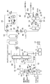
- FIG. 1 is a system diagram schematically showing a high moisture coal gasification system according to a first embodiment of the present invention. It is a systematic diagram which shows typically the high moisture coal gasification system which concerns on 2nd Embodiment of this invention. It is a systematic diagram which shows typically the high moisture coal gasification system which concerns on 3rd Embodiment of this invention. It is a systematic diagram which shows typically the high moisture coal gasification system which concerns on 4th Embodiment of this invention. It is a functional block diagram of the control apparatus provided in the high moisture coal gasification system of FIG.
- FIG. 1 shows a system (powder) for supplying powder containing inorganic substances and having hygroscopicity (hereinafter referred to as hygroscopic powder containing inorganic substances) between the solid fuel 1 pulverizing means and the gasifier.
- hygroscopic powder containing inorganic substances hygroscopic powder containing inorganic substances
- the solid fuel 1 is dried by a drying device (drying means) 2, pulverized by a pulverization device (pulverization means) 3, and then pressurized and stored at a predetermined pressure by a lock hopper 5. 6 is transferred.
- the solid fuel 1 is accompanied by the inert gas 8 and supplied to the gasification furnace 19 through the solid fuel transfer pipe 12 and the solid fuel burner 13.
- the transport path of the solid fuel 1 from the lock hopper 5 through the feed hopper 6 to the gasification furnace 19 flows the solid fuel 1 dried by the drying device 2 and pulverized by the pulverization device 3 into the gasification furnace 19.
- An airflow conveying means for conveying is configured.
- N 2 , CO 2, or the like is suitable for the inert gas 8 used for transferring and transporting the solid fuel 1.
- nitrogen 17 produced by supplying air 14 to the air separator 16 may be used.
- CO 2 in the inert gas 8 CO 2 (hereinafter, recovered CO 2 is referred to as (101)) was recovered in the gasification system preferably used. For example, extracting a portion of the recovered CO 2 (101), and pressurized to a predetermined pressure in the recycled CO 2 compressor 59, is used as the recycled CO 2 (102).
- the flow rate of the reused CO 2 (102) is adjusted by the flow rate adjusting valve 58 of the reused CO 2 .
- a gasification system when CO 2 is used as the inert gas 8 will be described.
- the lock hopper pressure equalizing valve 9 and the feed hopper pressure equalizing valve 10 are opened to equalize the lock hopper 5 and the feed hopper 6. . Further, by introducing an inert gas 8 (CO 2 in this embodiment) into the lock hopper 5, the stagnation of the solid fuel 1 at the outlet of the lock hopper 5 and the transfer valve 7 is prevented.
- the pressure adjustment valve 11 is used for adjusting the pressure of each hopper during transfer.
- CO 2 containing fine solid fuel 1 (dust form) is exhausted.
- the exhausted CO 2 may be reused as the inert gas 8 or may be mixed into the stored CO 2 (103) system.
- mixing into the system of stored CO 2 (103) it is necessary to remove dust in the CO 2 exhausted by the dedusting process.
- the solid fuel 1 transferred to the feed hopper 6 is accompanied by an inert gas 8 (CO 2 in this embodiment), and is supplied to the gasification furnace 19 via the solid fuel transfer pipe 12 and the solid fuel burner 13. .
- the solid fuel 1 charged into the gasification furnace 19 is mixed with the oxygen 18 similarly charged from the solid fuel burner 13 and gasified to generate a high-temperature product gas 20.
- the main components of the product gas 20 are CO and H 2 .
- the oxygen 18 introduced into the gasifier 19 is produced by the air separator 16.
- the air 14 is pressurized by a compressor 15 and supplied to an air separator 16 to be separated into nitrogen 17 and oxygen 18.
- the energy efficiency can be improved by electrolyzing water with electric power generated by natural energy such as sunlight or wind power to produce at least a part of oxygen 18. I do not care.
- the product gas 20 that has reached a high temperature is supplied to the product gas cooling unit 21.
- the spray water 62 whose pressure has been increased to a predetermined pressure is introduced to cool the product gas 20.
- a atomization nozzle is installed at the inlet of the spray water 62 of the product gas cooling unit 21.
- water 46 recovered from the product gas after the shift reaction, which will be described later, or cooling water for molten slag generated in the gasification furnace 19, is used to finish the system with a reduced amount of industrial water. And good.
- the generated gas cooling unit 21 is supplied with the water vapor 60 including the scattered fuel generated in the drying device 2 of the solid fuel 1, and the surplus moisture contained in the solid fuel 1 is also effectively used.
- the drying apparatus 2 is operated at a pressure close to normal pressure, and the generated gas cooling unit 21 is operated under pressure. For this reason, the water vapor 60 including the scattered fuel is pressurized by the compressor 61 and then supplied to the product gas cooling unit 21.
- a system in which the water vapor 60 including the scattered fuel is supplied to the upstream side of the spray water 62 and mixed with the high-temperature product gas 20 is shown. If the temperature of the product gas 20 after being mixed with the steam 60 containing the scattered fuel can be maintained at about 1000 ° C. or more, an aqueous shift reaction (CO + H 2 O ⁇ CO 2) by the steam introduced and CO in the product gas. + H 2 ) proceeds. If the shift reaction can be advanced by the product gas cooling unit 21, the amount of shift reaction catalyst used in the downstream shift reactor can be reduced, and the amount of shift reaction water 39 used can be reduced.
- the spray water 62 is introduced from the upstream side of the water vapor 60 including the scattered fuel.
- a system (not shown) may be used.
- the produced gas 22 after cooling is freed of the char 24 accompanied by the dust removing device (dust removing means) 23, halogenated substances such as chlorine in the washing tower 31, and fine particles that could not be removed by the dust removing device 23.
- the sulfur content is further removed by the desulfurization device 32.
- the char 24 separated from the product gas 22 after cooling is stored in the charlock hopper 25 and appropriately transferred to the char feed hopper 26, and then to the gasification furnace 19 through the char transport pipe 63 and the char burner 64. It is thrown in.
- the transport path of the char 24 from the charlock hopper 25 through the char feed hopper 26 to the gasification furnace 19 constitutes a char air transport means for transporting the char 24 collected by the dust removing device 23 to the gasification furnace 19. .
- An inert gas 8 is used as the carrier gas for the char 24.
- a system in which reused CO 2 (102) is used as the carrier gas in the same manner as the solid fuel 1 will be described.
- the method of transferring and transporting the char 24 is the same as the method of the solid fuel 1 described above.
- the char lock hopper pressure equalizing valve 28 and the char feed hopper pressure equalizing valve 29 are opened to equalize the char lock hopper 25 and the char feed hopper 26, and then the char transfer valve 27 is opened to transfer the char 24.
- Inert gas 8 (CO 2 in this embodiment) is introduced to promote the transfer of the char 24 and to adjust the pressure of the hopper, and the pressure of these hoppers is adjusted by adjusting the opening of the char system pressure regulating valve 30.
- the product gas 33 after desulfurization whose main components are CO, H 2 , CO 2 , H 2 O (water vapor) is about 200-300 ° C. by the product gas heat exchanger 34 and the product gas heater 35. Heated and fed to the first shift reactor 36.
- the heating temperature of the product gas 33 after desulfurization is set according to the characteristics of the shift reaction catalyst charged in the first shift reactor 36.
- the desulfurized product gas 33 is mixed with the shift reaction steam 42, and the shift reaction proceeds. If the shift reaction, which is an exothermic reaction, proceeds excessively, there is a risk that the reaction vessel and the shift reaction catalyst will be damaged by the high-temperature product gas. For this reason, it is preferable to install a plurality of shift reactors and advance the shift reaction step by step while cooling the product gas. In this embodiment, a case where two shift reactors are installed will be described.
- the shift reaction rate is adjusted according to the use of the product gas (H 2 , methane, methanol, DME (dimethyl ether), SNG (synthetic natural gas)), and the CO and H 2 in the product gas 38 after the shift reaction are adjusted. It is necessary to adjust the content ratio to a predetermined ratio. Adjustment of this shift reaction rate may be handled by operating conditions such as the temperature of the shift reactor and the amount of steam added, and by increasing or decreasing the catalyst charge amount. In some cases, a system that bypasses the second shift reactor 37 may be provided.
- the product gas 33 after desulfurization is cooled to a predetermined temperature downstream of the first shift reactor 36 and then supplied to the second shift reactor 37.
- a heat exchanger 41 of the product gas after the first shift reaction and the water for the shift reaction may be used, and the heat of the shift reaction may be used for preheating the steam 42 for the shift reaction.
- the product gas 38 after the shift reaction is about 40 ° C. in the product gas heat exchanger 34, the product gas after the shift reaction and the heat exchanger 40 for water for the shift reaction, and the product gas cooler 44 after the shift reaction. Until cooled.
- the condensed water generated in this cooling process is separated in the knockout drum 45 and recovered as water 46 recovered from the product gas 38 after the shift reaction.
- the water 46 recovered from the product gas 38 after the shift reaction is preferably reused in the gasification system as the spray water 62 or the like.
- the water 46 recovered from the product gas 38 after the shift reaction may be mixed with by-products such as CO remaining in the product gas 38 after the shift reaction and methanol generated from H 2 O (water vapor). .
- the water 46 recovered from the product gas 38 after the shift reaction is sprayed on the product gas cooling unit 21 and evaporated to be decomposed into a by-product such as methanol. Thereby, the processing apparatus of the by-product contained in the water 46 collect
- Product gas 38 after the shift reaction is cooled to about 40 ° C. is removed CO 2 in the CO 2 absorber 47, the product gas 48 after CO 2 absorption.
- the generated gas 48 after absorption of CO 2 is used as fuel, chemical infrastructure, etc. for power generation and social infrastructure.
- CO 2 absorption liquid 53 containing methyldiethanolamine as a main component comes into contact with the product gas 38 after the shift reaction to separate and remove CO 2 .
- CO 2 absorbed CO 2 absorbing liquid 49 is a heater 51 of the CO 2 absorbing solution heat exchanger 50, CO 2 absorbing solution is heated to 100 ° C. or higher is supplied to the CO 2 regeneration tower 52.
- CO 2 contained in the CO 2 absorbent 49 that has absorbed CO 2 is released.
- the CO 2 absorbing liquid 49 that CO 2 absorption reuse becomes possible as the CO 2 absorbing liquid 53.
- the CO 2 absorption liquid 53 is pressurized by a CO 2 absorption liquid booster pump 54, cooled to about 40 ° C. by the CO 2 absorption liquid heat exchanger 50, and supplied to the CO 2 absorption tower 47.
- the water content of the solid fuel 1 at the outlet of the drying device 2 is the conventional general system (about 15 wt%). Below) is set higher.
- the high moisture coal gasification system with high energy efficiency which reduced the motive power for drying the solid fuel 1 with the drying apparatus 2 from the conventional general system. Can be built.
- the solid fuel 1 having a high water content is supplied to the pulverizer 3, and the solid fuel 1 may adhere to the inner wall of the pulverizer 3.
- the pulverizing apparatus 3 is operated at a temperature higher than normal temperature (for example, about 40 to 70 ° C.) and may reach a higher temperature locally due to frictional heat during pulverization. For this reason, moisture remaining in the solid fuel 1 may evaporate inside the pulverizer 3.
- the evaporated water is cooled and condensed by the outside air in the vicinity of the inner wall of the pulverizer 3, and may adhere to and accumulate on the inner wall together with the solid fuel 1.
- the solid fuel 1 adhering / depositing inside the pulverizing apparatus 3 has a risk of impeding the operation of the pulverizing apparatus 3 or causing spontaneous ignition.
- a supply system for the hygroscopic powder 4A containing an inorganic substance is installed in the pulverizer 3.
- the powder 4 ⁇ / b> A supplied into the pulverizing device 3 absorbs moisture evaporated in the pulverizing device 3, is discharged together with the solid fuel 1, and is stored in the lock hopper 5.
- the inert gas 8 is supplied to increase the pressure to a predetermined pressure, and the solid fuel 1 is stored for several tens of minutes at maximum (the storage time varies depending on the hopper capacity and the supply amount of the solid fuel 1). If the solid fuel 1 having a temperature higher than the outside air temperature is stored, the inert gas 8 having a temperature higher than the outside air temperature is supplied at the time of pressurization or transfer, or the outside air temperature decreases during storage, etc. The internal temperature of the lock hopper 5 becomes higher than the external temperature.
- moisture evaporated from the solid fuel 1 may be condensed on the wall surface of the lock hopper 5 where the ambient temperature decreases due to heat radiation to the outside air or in the vicinity of the entrance / exit.
- the entrance / exit of the hopper may be blocked.
- a supply system for the hygroscopic powder 4B containing an inorganic substance is installed in the lock hopper 5.
- the powder 4 ⁇ / b> B supplied into the lock hopper 5 absorbs water evaporated from the solid fuel 1 stored in the lock hopper 5, and is transferred to the feed hopper 6 through the solid fuel transfer valve 7 together with the solid fuel 1. Is done.
- the water evaporated from the solid fuel 1 may be condensed. If the solid fuel 1 adheres and accumulates along with the condensed moisture at the entrance of the hopper, the inner wall, the vicinity of the entrance of the transport pipe 12 and the inside of the transport pipe 12, the flow rate of the solid fuel 1 supplied to the gasification furnace 19 is remarkably increased. May decrease.
- the char 24 having a higher water content is collected and stored in the charlock hopper 25 and transferred to the char feed hopper 26 than when the solid fuel having a low water content is used.
- the gasification furnace 19 is charged via the char burner 64. If the char 24 having a temperature higher than the outside temperature is stored, the inert gas 8 having a temperature higher than the outside temperature is supplied at the time of pressurization or transfer, or the outside temperature falls during the storage, The internal temperature of the charlock hopper 25 becomes higher than the external temperature.
- moisture evaporated from the char 24 may condense on the wall surface of the charlock hopper 25 or the vicinity of the entrance / exit where the ambient temperature decreases due to heat radiation to the outside air. If the char 24 adheres and accumulates with the condensed moisture, the entrance / exit of the charlock hopper 25 may be blocked.
- a supply system of hygroscopic powder 4C containing an inorganic substance is installed in the Charlock hopper 25.
- the powder 4 ⁇ / b> C supplied into the charlock hopper 25 absorbs moisture evaporated from the char 24 stored in the charlock hopper 25, and is transferred to the charfeed hopper 26 through the char transfer valve 27 together with the char 24.
- the hygroscopic powder containing inorganic substances will be described.
- the hygroscopic powder containing inorganic substances include coal ash, waste incineration ash, zeolite (including artificial zeolite made from coal ash, etc.), silica gel, calcium carbonate, and the like.
- the high moisture coal gasification system of the present embodiment when installed in the vicinity of a lignite boiler operating in the vicinity of a differential coal boiler or a lignite coal mine, the coal ash generated in these boilers is hygroscopic including inorganic substances. It is good to use it effectively as a powder.
- waste incineration ash generated in the waste incinerator may be used.
- the organic matter (unburned matter) contained in the coal ash and the waste incineration ash is gasified in the gasification furnace 19, and the inorganic substance is finally melted into slag in the gasification furnace 19.
- Molten slag can suppress the elution of heavy metals and the like in the inundation, which is a concern with coal ash and waste incineration ash, and can be effectively used as roadbed material and aggregate. This can contribute to detoxification of ash generated in boilers and waste incinerators and increased recycling.
- the pulverizer 3, the lock hopper 5, and the charlock hopper 25 are provided with a powder supply system for supplying hygroscopic powders 4 A, 4 B, and 4 C containing inorganic substances.
- 3 may be a powder supply system that supplies powder to any one or two of the lock hopper 5, the charlock hopper 25, and the charlock hopper 25, and in addition to these, powder that supplies hygroscopic powder containing inorganic substances. It may be a body supply system.
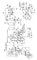
- FIG. 2 shows a system diagram of a high moisture coal gasification system provided with a system for supplying the char 24 collected by the dust removing means to the air current conveying means for the solid fuel.
- a plurality of solid fuel burners 13 and 13A are provided, and the char burner 64 is not provided.
- the char 24 collected by the dust removing device 23 is supplied to the lock hopper 5 and transferred to the feed hopper 6 together with the solid fuel 1.
- the solid fuel 1 supplied at normal pressure from the pulverizer 3 and the char 24 supplied at a pressure almost equal to the operating pressure of the gasifier 19 are supplied to the same lock hopper 5, and the feed hopper 6 is supplied. The operation procedure to transfer to will be described.
- the solid fuel 1 pulverized by the pulverizer 3 is supplied to the lock hopper 5 at substantially normal temperature and normal pressure.
- the hygroscopic powder 4B containing an inorganic substance is supplied to the lock hopper 5 together with the solid fuel 1 during this period when the lock hopper 5 is operated at normal pressure.
- the solid fuel supply valve 65 is closed and the inert gas 8 is introduced to raise the pressure of the lock hopper 5 to the same pressure as the dust removing device 23.
- the char supply valve 66 is opened, and the char 24 accumulated in the dust removing device 23 is supplied to the lock hopper 5.
- measures may be taken such as introducing the inert gas 8 into a pipe connecting the dust removing device 23 and the lock hopper 5 or installing a pressure equalizing pipe.
- the char 24 is operated at the operating temperature of the dedusting device 23. It flows into the lock hopper 5 at a near temperature, that is, a temperature considerably higher than room temperature. For this reason, in the lock hopper 5, the high-temperature char 24 and the high-moisture solid fuel 1 are in direct contact, and the water contained in the solid fuel 1 is evaporated by the sensible heat of the char 24. In order to prevent this moisture condensation, the hygroscopic powder 4B containing an inorganic substance is supplied to the lock hopper 5 and dehumidified.
- the reused CO 2 (102) that is adiabatically compressed by the reused CO 2 compressor 59 and heated to a temperature higher than room temperature is used as the inert gas 8 from the lock hopper 5 to the solid fuel burner 13
- a system that keeps the temperature up to 13A and promotes evaporation of moisture contained in the solid fuel 1 may be used.
- measures for heat insulation for example, installation of heat insulation steam pipes, heaters, heat insulation materials, etc.
- hygroscopic powder containing inorganic substances is reduced due to the reduced risk of condensation of evaporated water due to temperature drop.
- the supply amount of the body 4B can be reduced.
- the solid fuel 1 and the inert gas 8 can be preheated and put into the gasification furnace 19, it leads to prevention of the temperature fall in the gasification furnace 19.
- the char supply valve 66 is closed, the inert gas 8 is introduced, the pressure of the lock hopper 5 is increased, and the same pressure as that of the feed hopper 6 is set.
- the feed hopper pressure equalizing valve 10 is opened, and the pressure adjusting valve 11 equalizes the pressure with the feed hopper 6 continuously supplying the solid fuel 1 to the gasification furnace 19 at a constant pressure. Then, the solid fuel transfer valve 7 is opened, and the solid fuel 1 and the char 24 are transferred from the lock hopper 5 to the feed hopper 6. In order to prevent stagnation of the transfer of powder at the bottom of the lock hopper 5, it may be vibrated by striking or the like, or an inert gas 8 may be introduced.
- the solid fuel 1 and the char 24 transferred to the feed hopper 6 are transported by an inert gas 8 and supplied to the gasifier 19 via the solid fuel transport pipe 12 and the solid fuel burners 13 and 13A.
- a distributor 67 is installed between the feed hopper 6 and the gasification furnace 19.
- the former will be described as an example, but either may be used or both may be combined.
- the hygroscopic powders 4A and 4B containing inorganic substances have been described in the system for supplying the pulverizer 3 and the lock hopper 5.
- the feed hopper 6, the solid fuel transport pipe 12 and the distributor 67 are described.
- it may be supplied from other places from the pulverizing means to the gasification furnace.
- the char 24 having a temperature higher than the normal temperature recovered by the dust removing device 23 is supplied to the transport system of the solid fuel 1 supplied with high moisture, and is brought into direct contact with the solid fuel 1 at the normal temperature to be in contact with the solid fuel. 1 and conveyed to the gasification furnace 19. Even when the moisture contained in the solid fuel 1 evaporates due to the sensible heat of the char 24 when the solid fuel 1 is transported and transported, the moisture absorption including the inorganic substance introduced from the pulverizer 3 to the gasifier 19 as in this embodiment. Water is dehumidified with water-soluble powders 4A and 4B to prevent moisture condensation. Thereby, it is possible to construct a gasification system for a high moisture solid fuel that is excellent in energy efficiency by reducing the drying power of the solid fuel 1 and that is a simple system that does not require the transport system of the char 24.
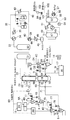
- FIG. 3 shows a system (powder that individually feeds solid fuel and char to a gasification furnace in a plurality of systems, and individually supplies powder containing inorganic substances and having hygroscopic properties to the pulverizer and each hopper of each system.
- a system diagram of a high moisture coal gasification system provided with a body supply system) is shown. In the present embodiment, parts different from FIG. 1 shown in the first embodiment will be mainly described.
- the solid fuel 1 is dried by a drying device (first drying means) 2A, pulverized by a pulverizing device 3, and then the lock hopper 5 for supplying the solid fuel 1 to the upper burner 68, and the solid fuel 1 are further added. It is supplied to a drying device (second drying means) 2B for drying.
- the water content of the solid fuel 1 after being dried by the drying device 2A is selected as a value that satisfies all of the pulverization device 3, the air flow to the gasification furnace 19, and the securing of the temperature in the gasification furnace 19.
- the pulverizing device 3 is supplied with hygroscopic powder 4A containing an inorganic substance and dehumidifies the moisture evaporated inside, thereby preventing moisture condensation inside.
- the solid fuel 1 stored in the lock hopper 5 is transferred to the feed hopper 6, and accompanied by the inert gas 8 to the gasifier 19 through the solid fuel transfer pipe 69 and the upper burner 68 to the upper burner. Is done.
- the lock hopper 5 and the feed hopper 6 are supplied with hygroscopic powders 4B and 4F containing an inorganic substance to dehumidify the moisture evaporated inside the hopper and prevent moisture condensation inside.
- the gasification furnace 19 is provided with a plurality of stages of burners having different heights, and the lower part of the furnace is heated to melt inorganic slag in the solid fuel 1, and the upper part of the furnace is set at a lower temperature than the lower part of the furnace.
- a method of promoting gasification of combustible components (carbon, hydrogen, etc.) in the solid fuel 1 is used.
- CO 2 gasification reaction (C + CO 2 ⁇ 2CO) is promoted by using CO 2 as the inert gas 8
- water vapor gasification reaction C + H 2 O ⁇ CO is promoted by increasing the moisture contained in the solid fuel 1). + H 2 ) is expected.
- the moisture of the solid fuel 1 introduced from the upper burner 68 is set higher than the moisture of the solid fuel 1 introduced from the lower burner 70.
- an operation for preventing moisture condensation is indispensable.
- the water contained in the solid fuel 1 is roughly classified into two types: water adhering to the particle surface and water bonded chemically to the solid content by hydrogen bonding or ionic reaction.
- the sensible heat up to the boiling point (at 100 ° C. at normal pressure) and latent heat of vaporization are required for drying the attached water.
- the latter combined water requires additional thermal energy that breaks the chemical bond and extracts H 2 O. From the viewpoint of improving the energy efficiency of the gasification system, it is desirable that the moisture of the solid fuel 1 after being dried by the drying device 2A is set to a value that dries at least a part of the former adhering water.
- the solid fuel 1 introduced from the lower burner 70 is supplied to the drying device 2B and further dried. Thereafter, the solid fuel 1 is stored in the lower burner system lock hopper 72, transferred to the lower burner system feed hopper 73, and accompanied by the inert gas 8, the lower burner system solid fuel transfer pipe 71, the lower burner.
- the gasification furnace 19 is charged through 70.
- the lower burner-type lock hopper 72 and the lower burner-type feed hopper 73 are supplied with hygroscopic powders 4D and 4G containing inorganic substances to dehumidify the moisture evaporated inside the hopper and prevent moisture condensation inside.
- the char feed hopper 26 is also supplied with hygroscopic powder 4H containing an inorganic substance to dehumidify moisture evaporated inside the hopper and prevent moisture condensation inside.
- the pulverizing device 3 the solid fuel 1 and the hoppers 5 and 72 of the conveying means are respectively provided with inorganic substances. Condensation of moisture is prevented by providing a separate powder supply system having moisture absorption and dehumidifying. In addition, by adjusting the moisture suitable for gasification of the solid fuel 1, it is possible to construct a gasification system for a high-moisture solid fuel excellent in energy efficiency by reducing the drying power of the solid fuel that is the pretreatment.
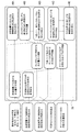
- FIG. 4 shows the moisture content of the solid fuel after drying, and the supply amount of the hygroscopic powder containing an inorganic substance to be introduced into each of the pulverizing means, the air transport means for the solid fuel and char, and the gasification furnace.
- the high moisture coal gasification system which provided the control apparatus which adjusts each is shown.
- parts different from FIG. 3 shown in the third embodiment will be mainly described.
- a system for supplying hygroscopic powder 4E containing an inorganic substance to the gasification furnace 19 is newly provided.
- the inorganic substance (ash) contained in the solid fuel 1 is added with the inorganic substance contained in the hygroscopic powder 4E containing the inorganic substance, and the flow rate of the inorganic substance and the viscosity of the molten slag to be melted into slag in the gasification furnace 19 are adjusted.
- the function of adjusting and maintaining the slag coating formed in the lower part in the gasification furnace 19 is also added.
- a control device 78 incorporating the respective flow rate adjustment functions of the hopper 72 and the gasification furnace 19 is provided. An outline of the flow rate adjustment logic in the control device 78 will be described.
- the total moisture the amount of moisture contained in the solid fuel before drying
- the adhering moisture total moisture-attached moisture is calculated from the combined moisture
- Ash ie, inorganic matter
- ash melting point and ash composition and industrial analysis (composition of organic matter such as C, H, O).
- the water content of the solid fuel 1 to be charged into the gasification furnace 19 and the oxygen content for gasifying the solid fuel 1 are set.
- the target moisture (target moisture content) of the solid fuel after drying in the drying device 2A and the drying device 2B, the predicted value of the amount of water evaporated in the pulverizing device 3 together with the operating temperature of the pulverizing device 3, and after cooling The temperature of the product gas 22 and the content ratio of water vapor are respectively set.
- the predicted value of the amount of water evaporated in the pulverizer 3, the temperature of the product gas 22 after cooling, and the content ratio of water vapor are set in the control device 78.
- the supply temperature of the inert gas 8 and the target temperature of the inner wall of the charlock hopper 25 are determined, and together with the analysis value of the solid fuel 1, the lock hopper 5 and the lower burner for supplying the solid fuel 1 to the upper burner 68.
- the predicted values of the amount of water evaporated by the lock hopper 72 and the charlock hopper 25 of the system are predicted, and the predicted values are set in the control device 78.
- the control device 78 prevents condensation of evaporated water inside the crushing device 3, the lock hopper 5, the lower burner lock hopper 72, and the charlock hopper 25.
- the flow rates of the hygroscopic powders 4A, 4B, 4C, and 4D containing the inorganic substances necessary for the measurement are obtained.
- the gasification furnace 19 is set so that the hygroscopic powder 4E containing the insufficient inorganic substance is charged into the gasification furnace 19.
- the flow rate of the powder 4E to be charged into the powder is obtained, and the powders 4A, 4B are controlled by controlling a control valve or the like provided in the powder supply system so that the powders 4A, 4B, 4C, 4D having the obtained flow rates are supplied. 4C, 4D are supplied.
- it may be incorporated in the control device 78 described above.
- the supply amount of the hygroscopic powders 4G and 4H containing inorganic substances supplied to the lower burner feed hopper 73 and the char feed hopper 26 may also be incorporated into the control device 78 as logic to be set in the same manner as described above.
- the target moisture of the solid fuel 1 after drying is set, and the moisture absorption including the inorganic substance for establishing the pulverization and air flow conveyance of the solid fuel 1 with this target moisture is established.
- a control device 78 having a function of setting the supply amount of the conductive powder and maintaining the slag coating logic formed in the gasification furnace 19, the drying power of the solid fuel 1 is reduced and energy efficiency is reduced.
- An excellent and high moisture solid fuel gasification system capable of stably conveying the high moisture solid fuel 1 to the gasification furnace 19 is constructed.
- this invention is not limited to the above-mentioned embodiment and modification which were demonstrated as an example, If it is the range which does not deviate from the technical idea which concerns on this invention also except the above-mentioned embodiment etc. Various changes can be made according to the design and the like.
- lignite for example, low-grade coal such as subbituminous coal, biomass, waste, etc.
- low-grade coal such as subbituminous coal, biomass, waste, etc.
- SYMBOLS 1 Solid fuel, 2, 2A, 2B ... Drying device, 3 ... Crushing device, 4A, 4B, 4C, 4D, 4E, 4F, 4G, 4H ... Hygroscopic powder containing an inorganic substance, 5 ... Lock hopper, 6 DESCRIPTION OF SYMBOLS ... Feed hopper, 7 ... Solid fuel transfer valve, 8 ... Inert gas, 9 ... Lock hopper pressure equalizing valve, 10 ... Feed hopper pressure equalizing valve, 11 ... Pressure regulating valve, 12 ... Solid fuel conveying pipe, 13, 13A ... Solid fuel burner, 14 ... air, 15 ... compressor, 16 ... air separator, 17 ... nitrogen, 18 ...
- Heat exchanger for product gas after shift reaction and water for shift reaction 41 ... Product gas after first shift reaction and for shift reaction 42 ... Water vapor for shift reaction, 43 ... Heater for water vapor for shift reaction, 44 ... Cooler for product gas after shift reaction, 45 ... Knockout drum, 46 ... Product gas after shift reaction Collected water, 47 ... CO 2 absorption tower, 48 ... CO 2 absorbed product gas, 49 ... CO 2 absorbed CO 2 absorbent, 50 ... CO 2 absorbent heat exchanger, 51 ... CO 2 absorbent Heater, 52 ... CO 2 regeneration tower, 53 ... CO 2 absorbing solution, 54 ... CO 2 absorbing liquid booster pump, 55 ... CO 2 absorbing solution for thermal regeneration, 56 ... CO 2 absorbing solution regeneration heater, 57 ...
Landscapes
- Chemical & Material Sciences (AREA)
- Engineering & Computer Science (AREA)
- Combustion & Propulsion (AREA)
- Oil, Petroleum & Natural Gas (AREA)
- Organic Chemistry (AREA)
- Solid Fuels And Fuel-Associated Substances (AREA)
- Gasification And Melting Of Waste (AREA)
Priority Applications (1)
| Application Number | Priority Date | Filing Date | Title |
|---|---|---|---|
| AU2019235819A AU2019235819C1 (en) | 2018-03-16 | 2019-03-15 | Solid fuel gasification system |
Applications Claiming Priority (2)
| Application Number | Priority Date | Filing Date | Title |
|---|---|---|---|
| JP2018050243A JP6708683B2 (ja) | 2018-03-16 | 2018-03-16 | 固体燃料のガス化システム |
| JP2018-050243 | 2018-03-16 |
Publications (1)
| Publication Number | Publication Date |
|---|---|
| WO2019177149A1 true WO2019177149A1 (ja) | 2019-09-19 |
Family
ID=67906822
Family Applications (1)
| Application Number | Title | Priority Date | Filing Date |
|---|---|---|---|
| PCT/JP2019/010842 Ceased WO2019177149A1 (ja) | 2018-03-16 | 2019-03-15 | 固体燃料のガス化システム |
Country Status (3)
| Country | Link |
|---|---|
| JP (1) | JP6708683B2 (enExample) |
| AU (1) | AU2019235819C1 (enExample) |
| WO (1) | WO2019177149A1 (enExample) |
Cited By (2)
| Publication number | Priority date | Publication date | Assignee | Title |
|---|---|---|---|---|
| WO2024257735A1 (ja) * | 2023-06-13 | 2024-12-19 | 三菱重工業株式会社 | 生成システム |
| WO2024257734A1 (ja) * | 2023-06-13 | 2024-12-19 | 三菱重工業株式会社 | ロックホッパの運転方法、および固体移動装置 |
Families Citing this family (1)
| Publication number | Priority date | Publication date | Assignee | Title |
|---|---|---|---|---|
| JP7140726B2 (ja) | 2019-08-28 | 2022-09-21 | 三菱重工業株式会社 | 炭素系燃料のガス化発電システム |
Citations (4)
| Publication number | Priority date | Publication date | Assignee | Title |
|---|---|---|---|---|
| JP2005126629A (ja) * | 2003-10-27 | 2005-05-19 | Mitsubishi Heavy Ind Ltd | 被溶融物排出設備及び被溶融物排出設備の運転方法 |
| JP2008266038A (ja) * | 2007-04-16 | 2008-11-06 | Central Res Inst Of Electric Power Ind | 組成調整された石炭ガス化スラグの製造方法 |
| JP2013170463A (ja) * | 2012-02-17 | 2013-09-02 | Mitsubishi Heavy Ind Ltd | 湿潤燃料を用いて複合発電を行うプラント及びその燃料乾燥方法 |
| JP2014149197A (ja) * | 2013-01-31 | 2014-08-21 | Mitsubishi Heavy Ind Ltd | 湿潤原料の粒子閉塞検知装置及び方法 |
-
2018
- 2018-03-16 JP JP2018050243A patent/JP6708683B2/ja active Active
-
2019
- 2019-03-15 WO PCT/JP2019/010842 patent/WO2019177149A1/ja not_active Ceased
- 2019-03-15 AU AU2019235819A patent/AU2019235819C1/en active Active
Patent Citations (4)
| Publication number | Priority date | Publication date | Assignee | Title |
|---|---|---|---|---|
| JP2005126629A (ja) * | 2003-10-27 | 2005-05-19 | Mitsubishi Heavy Ind Ltd | 被溶融物排出設備及び被溶融物排出設備の運転方法 |
| JP2008266038A (ja) * | 2007-04-16 | 2008-11-06 | Central Res Inst Of Electric Power Ind | 組成調整された石炭ガス化スラグの製造方法 |
| JP2013170463A (ja) * | 2012-02-17 | 2013-09-02 | Mitsubishi Heavy Ind Ltd | 湿潤燃料を用いて複合発電を行うプラント及びその燃料乾燥方法 |
| JP2014149197A (ja) * | 2013-01-31 | 2014-08-21 | Mitsubishi Heavy Ind Ltd | 湿潤原料の粒子閉塞検知装置及び方法 |
Cited By (3)
| Publication number | Priority date | Publication date | Assignee | Title |
|---|---|---|---|---|
| WO2024257735A1 (ja) * | 2023-06-13 | 2024-12-19 | 三菱重工業株式会社 | 生成システム |
| WO2024257734A1 (ja) * | 2023-06-13 | 2024-12-19 | 三菱重工業株式会社 | ロックホッパの運転方法、および固体移動装置 |
| TWI891396B (zh) * | 2023-06-13 | 2025-07-21 | 日商三菱重工業股份有限公司 | 閉鎖式料斗之運轉方法,以及固體移動裝置 |
Also Published As
| Publication number | Publication date |
|---|---|
| AU2019235819A1 (en) | 2020-11-12 |
| AU2019235819C1 (en) | 2024-08-15 |
| JP2019157094A (ja) | 2019-09-19 |
| AU2019235819B2 (en) | 2024-05-02 |
| JP6708683B2 (ja) | 2020-06-10 |
Similar Documents
| Publication | Publication Date | Title |
|---|---|---|
| CN101278034B (zh) | 用于将煤转化为特定组分的气体的系统 | |
| TWI558807B (zh) | 包含分段漿料添加之氣化系統及方法 | |
| KR101643792B1 (ko) | 2단계 건조 공급 기화 시스템 및 공정 | |
| CN101481631A (zh) | 用于气化器的燃料供给系统及气化系统启动的方法 | |
| WO2007037768A1 (en) | Solid waste gasification | |
| JP5848014B2 (ja) | 流動層乾燥装置 | |
| WO2019177149A1 (ja) | 固体燃料のガス化システム | |
| US20180051877A1 (en) | Ash sintering gasifier | |
| KR950011827B1 (ko) | 석탄과 석고의 가치있는 생성물로의 전환방법 | |
| JP4660874B2 (ja) | 廃棄物の二段ガス化システムの運転制御方法 | |
| JP2013108700A (ja) | 流動層乾燥装置 | |
| JP5693493B2 (ja) | 流動層乾燥装置及び石炭を用いたガス化複合発電システム | |
| AU2012248415A1 (en) | Fluidized bed drying apparatus and integrated coal gasification combined cycle system | |
| JP5851884B2 (ja) | 流動層乾燥装置、ガス化複合発電設備および乾燥方法 | |
| JP5713801B2 (ja) | 流動層乾燥装置 | |
| JP2016118346A (ja) | 微粉燃料製造装置 | |
| KR101100135B1 (ko) | 석탄 촤 재순환을 위한 석탄 가스화 장치 | |
| JP2014173790A (ja) | 低品位炭乾燥設備及びガス化複合発電システム | |
| WO2012133549A1 (ja) | 湿潤原料供給設備及び湿潤原料を用いたガス化複合発電システム | |
| JP5922338B2 (ja) | 流動層乾燥設備及び流動層乾燥設備を用いたガス化複合発電システム | |
| JP6231842B2 (ja) | ガス化炉を備えたガス化システム | |
| JP2012207840A (ja) | 流動層乾燥装置 | |
| JP2013167418A (ja) | 熱処理物の冷却装置 | |
| JP2013167378A (ja) | 流動層乾燥設備及び石炭を用いたガス化複合発電システム | |
| JP2012241988A (ja) | 流動層乾燥装置 |
Legal Events
| Date | Code | Title | Description |
|---|---|---|---|
| 121 | Ep: the epo has been informed by wipo that ep was designated in this application |
Ref document number: 19767916 Country of ref document: EP Kind code of ref document: A1 |
|
| NENP | Non-entry into the national phase |
Ref country code: DE |
|
| ENP | Entry into the national phase |
Ref document number: 2019235819 Country of ref document: AU Date of ref document: 20190315 Kind code of ref document: A |
|
| 122 | Ep: pct application non-entry in european phase |
Ref document number: 19767916 Country of ref document: EP Kind code of ref document: A1 |