WO2019176600A1 - 放電灯を含む光源装置、照射装置、および放電灯の判定方法 - Google Patents
放電灯を含む光源装置、照射装置、および放電灯の判定方法 Download PDFInfo
- Publication number
- WO2019176600A1 WO2019176600A1 PCT/JP2019/008241 JP2019008241W WO2019176600A1 WO 2019176600 A1 WO2019176600 A1 WO 2019176600A1 JP 2019008241 W JP2019008241 W JP 2019008241W WO 2019176600 A1 WO2019176600 A1 WO 2019176600A1
- Authority
- WO
- WIPO (PCT)
- Prior art keywords
- discharge lamp
- light source
- ultraviolet light
- switch
- turned
- Prior art date
- Legal status (The legal status is an assumption and is not a legal conclusion. Google has not performed a legal analysis and makes no representation as to the accuracy of the status listed.)
- Ceased
Links
Images



Classifications
-
- G—PHYSICS
- G01—MEASURING; TESTING
- G01R—MEASURING ELECTRIC VARIABLES; MEASURING MAGNETIC VARIABLES
- G01R31/00—Arrangements for testing electric properties; Arrangements for locating electric faults; Arrangements for electrical testing characterised by what is being tested not provided for elsewhere
- G01R31/24—Testing of discharge tubes
- G01R31/245—Testing of gas discharge tubes
-
- H—ELECTRICITY
- H01—ELECTRIC ELEMENTS
- H01J—ELECTRIC DISCHARGE TUBES OR DISCHARGE LAMPS
- H01J61/00—Gas-discharge or vapour-discharge lamps
- H01J61/82—Lamps with high-pressure unconstricted discharge having a cold pressure > 400 Torr
- H01J61/822—High-pressure mercury lamps
-
- G—PHYSICS
- G03—PHOTOGRAPHY; CINEMATOGRAPHY; ANALOGOUS TECHNIQUES USING WAVES OTHER THAN OPTICAL WAVES; ELECTROGRAPHY; HOLOGRAPHY
- G03F—PHOTOMECHANICAL PRODUCTION OF TEXTURED OR PATTERNED SURFACES, e.g. FOR PRINTING, FOR PROCESSING OF SEMICONDUCTOR DEVICES; MATERIALS THEREFOR; ORIGINALS THEREFOR; APPARATUS SPECIALLY ADAPTED THEREFOR
- G03F7/00—Photomechanical, e.g. photolithographic, production of textured or patterned surfaces, e.g. printing surfaces; Materials therefor, e.g. comprising photoresists; Apparatus specially adapted therefor
- G03F7/20—Exposure; Apparatus therefor
- G03F7/2002—Exposure; Apparatus therefor with visible light or UV light, through an original having an opaque pattern on a transparent support, e.g. film printing, projection printing; by reflection of visible or UV light from an original such as a printed image
- G03F7/2004—Exposure; Apparatus therefor with visible light or UV light, through an original having an opaque pattern on a transparent support, e.g. film printing, projection printing; by reflection of visible or UV light from an original such as a printed image characterised by the use of a particular light source, e.g. fluorescent lamps or deep UV light
-
- G—PHYSICS
- G03—PHOTOGRAPHY; CINEMATOGRAPHY; ANALOGOUS TECHNIQUES USING WAVES OTHER THAN OPTICAL WAVES; ELECTROGRAPHY; HOLOGRAPHY
- G03F—PHOTOMECHANICAL PRODUCTION OF TEXTURED OR PATTERNED SURFACES, e.g. FOR PRINTING, FOR PROCESSING OF SEMICONDUCTOR DEVICES; MATERIALS THEREFOR; ORIGINALS THEREFOR; APPARATUS SPECIALLY ADAPTED THEREFOR
- G03F7/00—Photomechanical, e.g. photolithographic, production of textured or patterned surfaces, e.g. printing surfaces; Materials therefor, e.g. comprising photoresists; Apparatus specially adapted therefor
- G03F7/20—Exposure; Apparatus therefor
- G03F7/2002—Exposure; Apparatus therefor with visible light or UV light, through an original having an opaque pattern on a transparent support, e.g. film printing, projection printing; by reflection of visible or UV light from an original such as a printed image
- G03F7/2008—Exposure; Apparatus therefor with visible light or UV light, through an original having an opaque pattern on a transparent support, e.g. film printing, projection printing; by reflection of visible or UV light from an original such as a printed image characterised by the reflectors, diffusers, light or heat filtering means or anti-reflective means used
-
- H—ELECTRICITY
- H01—ELECTRIC ELEMENTS
- H01J—ELECTRIC DISCHARGE TUBES OR DISCHARGE LAMPS
- H01J61/00—Gas-discharge or vapour-discharge lamps
- H01J61/02—Details
- H01J61/54—Igniting arrangements, e.g. promoting ionisation for starting
- H01J61/548—Igniting arrangements, e.g. promoting ionisation for starting using radioactive means to promote ionisation
-
- H—ELECTRICITY
- H05—ELECTRIC TECHNIQUES NOT OTHERWISE PROVIDED FOR
- H05B—ELECTRIC HEATING; ELECTRIC LIGHT SOURCES NOT OTHERWISE PROVIDED FOR; CIRCUIT ARRANGEMENTS FOR ELECTRIC LIGHT SOURCES, IN GENERAL
- H05B35/00—Electric light sources using a combination of different types of light generation
-
- H—ELECTRICITY
- H05—ELECTRIC TECHNIQUES NOT OTHERWISE PROVIDED FOR
- H05K—PRINTED CIRCUITS; CASINGS OR CONSTRUCTIONAL DETAILS OF ELECTRIC APPARATUS; MANUFACTURE OF ASSEMBLAGES OF ELECTRICAL COMPONENTS
- H05K3/00—Apparatus or processes for manufacturing printed circuits
- H05K3/02—Apparatus or processes for manufacturing printed circuits in which the conductive material is applied to the surface of the insulating support and is thereafter removed from such areas of the surface which are not intended for current conducting or shielding
- H05K3/027—Apparatus or processes for manufacturing printed circuits in which the conductive material is applied to the surface of the insulating support and is thereafter removed from such areas of the surface which are not intended for current conducting or shielding the conductive material being removed by irradiation, e.g. by photons, alpha or beta particles
-
- H—ELECTRICITY
- H05—ELECTRIC TECHNIQUES NOT OTHERWISE PROVIDED FOR
- H05B—ELECTRIC HEATING; ELECTRIC LIGHT SOURCES NOT OTHERWISE PROVIDED FOR; CIRCUIT ARRANGEMENTS FOR ELECTRIC LIGHT SOURCES, IN GENERAL
- H05B41/00—Circuit arrangements or apparatus for igniting or operating discharge lamps
- H05B41/02—Details
- H05B41/04—Starting switches
-
- H—ELECTRICITY
- H05—ELECTRIC TECHNIQUES NOT OTHERWISE PROVIDED FOR
- H05B—ELECTRIC HEATING; ELECTRIC LIGHT SOURCES NOT OTHERWISE PROVIDED FOR; CIRCUIT ARRANGEMENTS FOR ELECTRIC LIGHT SOURCES, IN GENERAL
- H05B45/00—Circuit arrangements for operating light-emitting diodes [LED]
Definitions
- the present invention relates to a light source device including a discharge lamp that emits light used for exposure of a printed wiring board or the like, an irradiation device, and a method for determining whether or not the discharge lamp is a genuine product.
- a printed wiring board in which a wiring pattern is formed of a metal such as copper on a substrate made of resin or glass epoxy material has been used to mount components on an electronic device.
- Photo-etching technology is used to form wiring patterns on these printed wiring boards. Photo-etching is performed by applying a photoresist, which is a photosensitive chemical, to the entire surface of the substrate on which the metal layer that will be the wiring is formed, and irradiating light from the exposure device through the same photomask as the wiring pattern.
- photoresists There are two types of photoresists: a negative type photoresist whose solubility is reduced by irradiation light and a positive type photoresist whose solubility is increased by irradiation light.
- the photoresist portion whose solubility has been relatively increased by irradiation light is removed by chemical treatment, and when the exposed metal layer is removed by etching, only the metal layer under the portion where the photoresist remains is left, and the photoresist is removed.
- a wiring pattern is formed on the substrate.
- a discharge lamp with a large light emission amount per lamp is used as a light source in order to ensure a uniform exposure amount over the entire irradiation surface. ing.
- a discharge lamp generates an arc discharge between a pair of electrodes that are spaced apart from each other in an airtight inner space of an arc tube, thereby exciting mercury enclosed in the inner space to emit ultraviolet light. Is made to emit light.
- a glow discharge is started between a pair of electrodes, and then the arc discharge is started.
- a vacuum environment is used. Therefore, it is necessary to cause dielectric breakdown between electrodes that are physically separated. In order to cause this dielectric breakdown, it is necessary to apply a high-frequency high voltage between the electrodes.
- a power supply device that applies such a high voltage is very expensive, and the generated high-frequency voltage is around the surroundings. The possibility of inducing machine malfunctions has also been pointed out. For this reason, various ideas have been proposed in order to start discharge at a low voltage or low frequency, that is, to improve the startability of the discharge lamp.
- Patent Document 1 describes a technique for improving startability by enclosing a startability promoting substance such as krypton 85 in the inner space of the arc tube.
- the present invention has been made in view of the above-mentioned problems, and its purpose is to obtain good startability without enclosing a startability promoting substance in the inner space of the arc tube in the discharge lamp, and Another object of the present invention is to provide a light source device, an irradiating device, and a method for determining whether or not the discharge lamp is a genuine product.
- a discharge lamp as a light source An irradiation apparatus is provided that includes an ultraviolet light source that irradiates the discharge lamp with ultraviolet light in order to detect whether the discharge lamp is a genuine product when the discharge lamp is started.
- the irradiation device includes a plurality of the discharge lamps, and the ultraviolet light source irradiates the plurality of discharge lamps with the ultraviolet light.
- the ultraviolet light source is attached in the vicinity of the discharge lamp, and one ultraviolet light source irradiates the ultraviolet light to one discharge lamp.
- the ultraviolet light source is an LED.
- the irradiation device comprises: A discharge lamp power supply for supplying lighting power to the discharge lamp; A power source for an ultraviolet light source that supplies power for lighting to the ultraviolet light source; A discharge lamp switch for turning on and off the power from the discharge lamp power supply; An ultraviolet light source switch for turning on and off the power from the ultraviolet light source; The discharge lamp switch and the ultraviolet light source switch have a function of turning on and off. The first time, the discharge lamp switch is turned on while the ultraviolet light source switch is turned off.
- the power for turning on the discharge lamp supplied from the power supply for the discharge lamp is turned off with the switch for turning on and off the power for turning on the ultraviolet light source supplied from the power supply for the ultraviolet light source turned off.
- Second time with the ultraviolet light source switch turned on, turn on the discharge lamp switch,
- the discharge lamp switch is turned on the second time. Only when the discharge lamp is lit, it is determined that the discharge lamp is a genuine product.
- FIG. 10 is a cross-sectional view illustrating an example of a light source device 100 according to Modification 3.
- FIG. 1 shows an exposure apparatus 10 according to a first embodiment to which the present invention is applied.
- the exposure machine 10 is generally composed of an irradiation device 50, an integrator 12, a concave mirror 14, and an irradiation surface 16.
- the irradiation device 50 emits light including a wavelength suitable for exposure of the exposure object X.
- the details of the irradiation apparatus 50 will be described after the configuration of the exposure apparatus 10 is described.
- the concave mirror 14 has a reflective concave surface 22 inside thereof.
- the concave mirror 14 reflects the light emitted from the integrator 12 by the reflecting concave surface 22 to make parallel light.
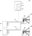
- FIG. 2 is a diagram showing an irradiation apparatus 50 according to the first embodiment to which the present invention is applied.
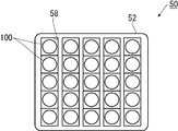
- FIG. 3 is a plan view of the irradiation device 50.
- the irradiation device 50 includes a plurality of light source devices 100, an ultraviolet light source 200, a frame 52, a discharge lamp switch 53, a discharge lamp power source 54, an ultraviolet light source switch 55, and an ultraviolet light source power source 56.
- Device 57 is a plurality of light source devices 100, an ultraviolet light source 200, a frame 52, a discharge lamp switch 53, a discharge lamp power source 54, an ultraviolet light source switch 55, and an ultraviolet light source power source 56.
- the ultraviolet light source 200 is an LED that emits ultraviolet light, and is incorporated in each light source device 100. Therefore, the description of the ultraviolet light source 200 in this embodiment will be made together with the description of the light source device 100.
- the ultraviolet light source 200 is not limited to an LED, and a high-pressure mercury lamp, a metal halide lamp, or the like may be used as long as it can emit ultraviolet light.
- a high-pressure mercury lamp, a metal halide lamp, or the like may be used as long as it can emit ultraviolet light.
- Modification 1 described later when irradiating a plurality of discharge lamps 110 with ultraviolet light, it is preferable to select a lamp with a large amount of light emission per unit.
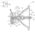
- the discharge lamp 110 has an arc tube portion 112 and a pair of seal portions 114 extending from the arc tube portion 112.
- the arc tube portion 112 and the pair of seal portions 114 are integrally formed of quartz glass. Furthermore, an inner space 116 sealed by a seal portion 114 is formed in the arc tube portion 112.
- each seal portion 114 of the discharge lamp 110 an embedded molybdenum foil 118 and one end made of tungsten having one end connected to one end of the foil 118 and the other end disposed in the internal space 116.
- a pair of electrodes 120 and a pair of lead rods 122 each having one end connected to the other end of the foil 118 and the other end extending from the seal portion 114 to the outside are provided.
- the internal space 116 is filled with a predetermined amount of mercury 124 and halogen (for example, bromine).
- one seal portion 114 is inserted into the seal portion insertion hole 156 of the reflector 150.
- the discharge lamp 110 may be for AC lighting or DC lighting.
- the reflector 150 has a bowl-shaped reflecting surface 152 on its inner surface.
- the reflecting surface 152 reflects a part of the light from the discharge lamp 110 arranged so that the arc tube portion 112 is located inside the reflector 150.
- the reflecting surface 152 is defined by a rotating paraboloid.
- the light emitting point generally, the center position of the arc formed between the pair of electrodes 120 in the internal space 116 in the discharge lamp 110 coincides with the focal point of the rotating paraboloid. Thereby, the light emitted from the light emitting point of the discharge lamp 110 and reflected by the reflecting surface 152 and then exiting the opening 154 of the reflector 150 becomes substantially parallel light.
- the shape of the reflecting surface 152 is not limited to this, and may be a spheroidal surface, another rotating surface, or a shape other than the rotating surface. Further, it is not essential to make the light emitting point coincide with the focal point, and the light emitting point may be shifted from the focal point as necessary.
- the light emitted from the discharge lamp 110 has a predetermined angle (opening angle) centered on the light traveling along the central axis CL of the reflecting surface 152. It will come ahead of the reflector 150 in the range with.
- the insulating base 170 is formed of an electrical insulator such as ceramic, and one seal portion in the discharge lamp 110 inserted in the bottom neck portion 155 and the seal portion insertion hole 156 of the reflector 150.
- a reflector insertion hole 172 into which 114 is inserted is formed.
- the insulating base 170 is formed with an inner space 174 communicating with the reflector insertion hole 172 described above, and further, a power cable insertion hole through which the power cable A is inserted by communicating the inner space 174 with the outer side. 176 is formed.
- the insulating base 170 and the discharge lamp 110 are fixed to each other by an inorganic adhesive C having electrical insulation and high thermal conductivity. More specifically, the end of the bottom neck portion 155 of the reflector 150 and one seal portion 114 of the discharge lamp 110 are inserted into the reflector insertion hole 172 of the insulating base 170, and the inner space 174 of the insulating base 170 is further inserted. In the state where the ultraviolet light source 200 and the power cable A are arranged, the inner space 174 is filled with the inorganic adhesive C.
- the ultraviolet light source 200 is attached in the vicinity of the discharge lamp 110, and more specifically, the end surface of the seal portion 114 on the side where the ultraviolet light from the ultraviolet light source 200 is inserted into the reflector insertion hole 172 in the discharge lamp 110. It is preferable to provide it at a position where it is emitted toward
- the frame 52 is a substantially rectangular parallelepiped member having a plurality of recesses 58 in which the plurality of light source devices 100 are mounted.
- the discharge lamp power supply 54 supplies necessary electric power (direct current or alternating current) to the discharge lamp 110 of each light source device 100 attached to the frame 52.
- the ultraviolet light source power source 56 is a power source that supplies a direct current to the ultraviolet light source 200 incorporated in each light source device 100, and the ultraviolet light source switch 55 turns on a constant DC current supplied to the ultraviolet light source 200. Turn off.
- the direct current supplied by the ultraviolet light source power supply 56 flows in the forward direction of the LEDs constituting the ultraviolet light source 200.
- the control unit 60 operates the discharge lamp switch 53 and the ultraviolet light source switch 55 to turn on / off the current supplied from the discharge lamp power supply 54 to the discharge lamp 110 and from the ultraviolet light source power supply 56 to the ultraviolet light source.
- 200 has a function of turning on and off the current supplied to the circuit 200.
- the control unit 60 basically performs two operations. That is, the control unit 60 turns on the discharge lamp switch 53 with the ultraviolet light source switch 55 turned off for the first time, and turns on the ultraviolet light source switch 55 for the second time. 53 is turned on.
- the determination unit 66 determines whether or not the discharge lamp 110 is lit in the first and second operations, and determines whether or not the discharge lamp 110 is a genuine product based on the determination result as described above. judge.
- the control unit 60 After the genuine product determination in the first light source device 100 is completed, the control unit 60 starts supplying current to the discharge lamp 110 in the other light source device 100. Thereafter, the genuine product determination is performed in the same manner as in the case of the first light source device 100 described above, and the same is performed until the determination of all the light source devices 100 is completed or the inspection of the light source devices 100 in a predetermined range is completed. Repeat the determination.
- the determination device 57 was able to determine whether or not the discharge lamp 110 was a genuine product. Thereby, it is possible to avoid erroneous use of the non-genuine discharge lamp 110 that is used for a long period of time and has a risk of explosion.
- the ultraviolet light source (LED) 200 is attached to each of the plurality of discharge lamps 110.
- the discharge lamp 110 in the plurality of light source devices 100 attached to the frame 52 is provided.
- One ultraviolet light source 200 may be arranged so that ultraviolet light can be irradiated toward the surface.
- the ultraviolet light from the ultraviolet light source 200 directly irradiates the arc tube portion 112 of the discharge lamp 110 through the opening 154 of each reflector 150 in the light source device 100.
- the number of ultraviolet light sources 200 to be arranged may be plural.
- the method for determining whether or not the discharge lamp 110 is a genuine product is the same as in the first embodiment.
- the discharge lamp switch 53 that supplies power to the discharge lamp 110 to be determined is turned on and the discharge lamp 110 lights up. Check whether or not.
- the discharge lamp switch 53 is turned on to check whether the discharge lamp 110 is lit.
- the discharge lamp 110 is turned on when both the discharge lamp switch 53 is turned on as a result of the first operation and the second operation, it is determined that the discharge lamp 110 is not a genuine product. If the discharge lamp 110 is turned on only when the discharge lamp switch 53 is turned on for the second time (that is, when the ultraviolet light source switch 55 is turned on), it is determined that the discharge lamp 110 is a genuine product. To do.
- the ultraviolet light source 200 of the light source device 100 in the above-described embodiment is composed of only LEDs, as shown in FIG. 8, the ultraviolet light source 200 is connected to the LED 202 and the incandescent lamp connected in series to the LED 202. 204, and may be provided in the light source device 100 (more precisely, in the inner space 174 of the insulating base 170 as in the first embodiment). Note that a fuse may be attached in series with the LED 202 or the incandescent lamp 204 for circuit protection or the like.
- the genuine product determination of the light source device 100 can be combined with the method using the ultraviolet light source 200 and the method using the incandescent lamp 204 as in the first embodiment described above. Both methods may be performed simultaneously, or either one may be performed.
- the both-ends voltage of the ultraviolet light source 200 is measured by a measurement unit (not shown; the same applies hereinafter) of the determination device 57 (first time).
- the measurement unit again measures the voltage across the ultraviolet light source 200 (second time).
- the measured voltage values at both ends are sent to the determination unit 66 of the determination device 57.
- the constant current flowing through the ultraviolet light source 200 is a direct current corresponding to the forward current of the LED 202.
- the determination unit 66 that has received the two voltage values at both ends checks whether or not the difference between the two voltage values at the two times is within a predetermined voltage range, and the difference between the two voltage values is within the predetermined voltage range. In this case, the determination unit 66 determines that the discharge lamp 110 to be inspected is a genuine product. Conversely, when the difference between the voltage values at both ends is not within the predetermined voltage range, the determination unit 66 determines that the discharge lamp 110 to be inspected is not a genuine product.
- the incandescent lamp 204 tends to increase in resistance value for a while (ten seconds) due to the characteristics of the filament contained therein. For this reason, the voltage value (for example, 8.5 V) of the ultraviolet light source 200 measured for the second time is larger than the value (for example, 2.0 V) of the same voltage measured for the first time. As a result, if the difference between the voltage values at both ends of the two measurements described above is within a predetermined voltage range (for example, between 6 and 7 V), it is determined that the discharge lamp 110 is a genuine product including the incandescent lamp 204. can do.
- a predetermined voltage range for example, between 6 and 7 V
- the ultraviolet light source 200 does not include the incandescent lamp 204. Therefore, the difference between the first measured value and the second measured value in the voltage value across the ultraviolet light source 200 is as follows. Nearly zero. Therefore, when the difference between the voltage values at both ends is not within the predetermined voltage range, the determination unit 66 determines that the discharge lamp 110 to be inspected is not a genuine product.
- the ultraviolet light source 200 that irradiates the ultraviolet light toward the discharge lamp 110 in the plurality of light source devices 100 attached to the frame 52 as in the first modification described above, not the LED 202 as shown in FIG. Only the incandescent lamp 204 may be provided in the light source device 100.
- the incandescent lamp 204 may be disposed in any of the insulating bases 170, or may be attached to the reflector container 151 by being disposed on the outer surface of the insulating base 170, the outer surface of the reflector 150, or the like. Also, a fuse may be attached in series with the incandescent lamp 204 for circuit protection or the like.
- the genuine product determination of the light source device 100 can combine the method using the ultraviolet light source 200 and the method using the incandescent lamp 204 as in the first modification. Both methods may be performed simultaneously, in sequence, or either one may be performed.
- the controller 60 continues to supply a constant current (either AC or DC) to the incandescent lamp 204 from the ultraviolet light source 56 or another power source (not shown). In this state, the measurement is performed by measuring the voltage across the pair of power cables A connected to the incandescent lamp 204 twice with a predetermined time (for example, 10 seconds).
- the voltage at both ends of the incandescent lamp 204 is measured by a measuring unit (not shown; the same applies hereinafter) of the determination device 57 (first time).
- the measurement unit again measures the voltage across the incandescent lamp 204 (second time). The measured voltage values at both ends are sent to the determination unit 66 of the determination device 57.
- the determination unit 66 that has received the two voltage values at both ends checks whether or not the difference between the two voltage values at the two times is within a predetermined voltage range, and the difference between the two voltage values is within the predetermined voltage range. In this case, the determination unit 66 determines that the discharge lamp 110 to be inspected is a genuine product. Conversely, when the difference between the voltage values at both ends is not within the predetermined voltage range, the determination unit 66 determines that the discharge lamp 110 to be inspected is not a genuine product.
- the discharge lamp 110 is a genuine product provided with the incandescent lamp 204
- the voltage value at the both ends of the incandescent lamp 204 is larger at the second measured value than at the first measured value.
- the reason for this is the same as that described in the second modification, and is omitted here.
- the discharge lamp 110 is a genuine product including the incandescent lamp 204. Can be determined.
- the determination unit 66 determines that the discharge lamp 110 to be inspected is not a genuine product.
Landscapes
- Physics & Mathematics (AREA)
- General Physics & Mathematics (AREA)
- Engineering & Computer Science (AREA)
- Manufacturing & Machinery (AREA)
- Microelectronics & Electronic Packaging (AREA)
- Exposure And Positioning Against Photoresist Photosensitive Materials (AREA)
- Non-Portable Lighting Devices Or Systems Thereof (AREA)
- Photometry And Measurement Of Optical Pulse Characteristics (AREA)
- Circuit Arrangements For Discharge Lamps (AREA)
Priority Applications (3)
| Application Number | Priority Date | Filing Date | Title |
|---|---|---|---|
| JP2020506403A JP7274761B2 (ja) | 2018-03-13 | 2019-03-01 | 放電灯を含む光源装置、照射装置、および放電灯の判定方法 |
| US16/978,331 US11913985B2 (en) | 2018-03-13 | 2019-03-01 | Light source device including discharge lamp, irradiation device and distinguishing method for discharge lamp |
| CN201980016097.6A CN111819496B (zh) | 2018-03-13 | 2019-03-01 | 包括放电灯的光源装置、照射装置以及放电灯的判定方法 |
Applications Claiming Priority (2)
| Application Number | Priority Date | Filing Date | Title |
|---|---|---|---|
| JP2018046077 | 2018-03-13 | ||
| JP2018-046077 | 2018-03-13 |
Publications (1)
| Publication Number | Publication Date |
|---|---|
| WO2019176600A1 true WO2019176600A1 (ja) | 2019-09-19 |
Family
ID=67907669
Family Applications (1)
| Application Number | Title | Priority Date | Filing Date |
|---|---|---|---|
| PCT/JP2019/008241 Ceased WO2019176600A1 (ja) | 2018-03-13 | 2019-03-01 | 放電灯を含む光源装置、照射装置、および放電灯の判定方法 |
Country Status (5)
| Country | Link |
|---|---|
| US (1) | US11913985B2 (https=) |
| JP (1) | JP7274761B2 (https=) |
| CN (1) | CN111819496B (https=) |
| TW (1) | TWI808136B (https=) |
| WO (1) | WO2019176600A1 (https=) |
Families Citing this family (1)
| Publication number | Priority date | Publication date | Assignee | Title |
|---|---|---|---|---|
| CN115167081A (zh) * | 2022-08-12 | 2022-10-11 | 无锡旭电科技有限公司 | 一种uvled大功率线路制程平行光源系统 |
Citations (5)
| Publication number | Priority date | Publication date | Assignee | Title |
|---|---|---|---|---|
| JP2007317529A (ja) * | 2006-05-26 | 2007-12-06 | Mitsubishi Electric Corp | 高圧放電ランプ |
| JP3137962U (ja) * | 2007-10-03 | 2007-12-13 | 岩崎電気株式会社 | 光源装置 |
| JP2009212041A (ja) * | 2008-03-06 | 2009-09-17 | Phoenix Denki Kk | 補助光源およびその補助光源を備える光源装置 |
| JP2011014247A (ja) * | 2009-06-30 | 2011-01-20 | Iwasaki Electric Co Ltd | 光源装置 |
| JP2016200751A (ja) * | 2015-04-13 | 2016-12-01 | フェニックス電機株式会社 | 光源装置及び露光装置とその検査方法 |
Family Cites Families (6)
| Publication number | Priority date | Publication date | Assignee | Title |
|---|---|---|---|---|
| JP4826446B2 (ja) * | 2006-11-27 | 2011-11-30 | ウシオ電機株式会社 | 光源装置 |
| JP3137961U (ja) * | 2007-10-03 | 2007-12-13 | 岩崎電気株式会社 | 光源装置 |
| DE102008058819A1 (de) * | 2007-11-28 | 2009-06-25 | Toshiba Lighting & Technology Corp. | Entladungslampenzündvorrichtung |
| JP4788719B2 (ja) | 2008-02-01 | 2011-10-05 | パナソニック株式会社 | 高圧放電ランプシステム、およびそれを用いたプロジェクタ |
| CA2761526A1 (en) * | 2009-05-14 | 2010-11-18 | Iwasaki Electric Co., Ltd. | Light source device |
| JP4995342B1 (ja) * | 2011-11-21 | 2012-08-08 | フェニックス電機株式会社 | 露光用光源およびこれを用いた露光装置 |
-
2019
- 2019-03-01 CN CN201980016097.6A patent/CN111819496B/zh active Active
- 2019-03-01 US US16/978,331 patent/US11913985B2/en active Active
- 2019-03-01 WO PCT/JP2019/008241 patent/WO2019176600A1/ja not_active Ceased
- 2019-03-01 JP JP2020506403A patent/JP7274761B2/ja active Active
- 2019-03-11 TW TW108107961A patent/TWI808136B/zh active
Patent Citations (5)
| Publication number | Priority date | Publication date | Assignee | Title |
|---|---|---|---|---|
| JP2007317529A (ja) * | 2006-05-26 | 2007-12-06 | Mitsubishi Electric Corp | 高圧放電ランプ |
| JP3137962U (ja) * | 2007-10-03 | 2007-12-13 | 岩崎電気株式会社 | 光源装置 |
| JP2009212041A (ja) * | 2008-03-06 | 2009-09-17 | Phoenix Denki Kk | 補助光源およびその補助光源を備える光源装置 |
| JP2011014247A (ja) * | 2009-06-30 | 2011-01-20 | Iwasaki Electric Co Ltd | 光源装置 |
| JP2016200751A (ja) * | 2015-04-13 | 2016-12-01 | フェニックス電機株式会社 | 光源装置及び露光装置とその検査方法 |
Also Published As
| Publication number | Publication date |
|---|---|
| JP7274761B2 (ja) | 2023-05-17 |
| TW201945858A (zh) | 2019-12-01 |
| TWI808136B (zh) | 2023-07-11 |
| CN111819496A (zh) | 2020-10-23 |
| US11913985B2 (en) | 2024-02-27 |
| JPWO2019176600A1 (ja) | 2021-03-11 |
| US20210003627A1 (en) | 2021-01-07 |
| CN111819496B (zh) | 2023-10-03 |
Similar Documents
| Publication | Publication Date | Title |
|---|---|---|
| CN106061077B (zh) | 曝光装置及其检查方法 | |
| JP7274761B2 (ja) | 放電灯を含む光源装置、照射装置、および放電灯の判定方法 | |
| JP5524931B2 (ja) | 補助ランプ付き高圧放電ランプ | |
| CN111066376B (zh) | 光源装置、曝光装置以及光源装置的判定方法 | |
| CN111033385B (zh) | 光源装置、曝光装置以及光源装置的判定方法 | |
| TWI794352B (zh) | 燈之點亮方法 | |
| KR102538972B1 (ko) | 광원 장치, 그것을 구비하는 조사 장치, 및 광원 장치의 점등 방법 |
Legal Events
| Date | Code | Title | Description |
|---|---|---|---|
| 121 | Ep: the epo has been informed by wipo that ep was designated in this application |
Ref document number: 19767306 Country of ref document: EP Kind code of ref document: A1 |
|
| ENP | Entry into the national phase |
Ref document number: 2020506403 Country of ref document: JP Kind code of ref document: A |
|
| NENP | Non-entry into the national phase |
Ref country code: DE |
|
| 122 | Ep: pct application non-entry in european phase |
Ref document number: 19767306 Country of ref document: EP Kind code of ref document: A1 |