WO2019172004A1 - スプリングシートおよびサスペンション取付構造 - Google Patents
スプリングシートおよびサスペンション取付構造 Download PDFInfo
- Publication number
- WO2019172004A1 WO2019172004A1 PCT/JP2019/007115 JP2019007115W WO2019172004A1 WO 2019172004 A1 WO2019172004 A1 WO 2019172004A1 JP 2019007115 W JP2019007115 W JP 2019007115W WO 2019172004 A1 WO2019172004 A1 WO 2019172004A1
- Authority
- WO
- WIPO (PCT)
- Prior art keywords
- spring seat
- flange
- upper mount
- spring
- mount
- Prior art date
- Legal status (The legal status is an assumption and is not a legal conclusion. Google has not performed a legal analysis and makes no representation as to the accuracy of the status listed.)
- Ceased
Links
Images



Classifications
-
- B—PERFORMING OPERATIONS; TRANSPORTING
- B60—VEHICLES IN GENERAL
- B60G—VEHICLE SUSPENSION ARRANGEMENTS
- B60G11/00—Resilient suspensions characterised by arrangement, location or kind of springs
- B60G11/14—Resilient suspensions characterised by arrangement, location or kind of springs having helical, spiral or coil springs only
- B60G11/16—Resilient suspensions characterised by arrangement, location or kind of springs having helical, spiral or coil springs only characterised by means specially adapted for attaching the spring to axle or sprung part of the vehicle
-
- B—PERFORMING OPERATIONS; TRANSPORTING
- B60—VEHICLES IN GENERAL
- B60G—VEHICLE SUSPENSION ARRANGEMENTS
- B60G15/00—Resilient suspensions characterised by arrangement, location or type of combined spring and vibration damper, e.g. telescopic type
- B60G15/02—Resilient suspensions characterised by arrangement, location or type of combined spring and vibration damper, e.g. telescopic type having mechanical spring
- B60G15/06—Resilient suspensions characterised by arrangement, location or type of combined spring and vibration damper, e.g. telescopic type having mechanical spring and fluid damper
-
- F—MECHANICAL ENGINEERING; LIGHTING; HEATING; WEAPONS; BLASTING
- F16—ENGINEERING ELEMENTS AND UNITS; GENERAL MEASURES FOR PRODUCING AND MAINTAINING EFFECTIVE FUNCTIONING OF MACHINES OR INSTALLATIONS; THERMAL INSULATION IN GENERAL
- F16F—SPRINGS; SHOCK-ABSORBERS; MEANS FOR DAMPING VIBRATION
- F16F9/00—Springs, vibration-dampers, shock-absorbers, or similarly-constructed movement-dampers using a fluid or the equivalent as damping medium
- F16F9/32—Details
-
- F—MECHANICAL ENGINEERING; LIGHTING; HEATING; WEAPONS; BLASTING
- F16—ENGINEERING ELEMENTS AND UNITS; GENERAL MEASURES FOR PRODUCING AND MAINTAINING EFFECTIVE FUNCTIONING OF MACHINES OR INSTALLATIONS; THERMAL INSULATION IN GENERAL
- F16F—SPRINGS; SHOCK-ABSORBERS; MEANS FOR DAMPING VIBRATION
- F16F9/00—Springs, vibration-dampers, shock-absorbers, or similarly-constructed movement-dampers using a fluid or the equivalent as damping medium
- F16F9/32—Details
- F16F9/54—Arrangements for attachment
Definitions
- Patent Document 1 discloses a vehicle suspension structure that can protect components such as bearings from muddy water.
- the vehicle suspension structure includes a shock absorber having a piston rod, a coil spring that rotates relative to the piston rod by a steering operation, a spring seat (upper seat) that supports the upper end of the coil spring, and a piston.
- An upper mount (upper support) for attaching the rod to the vehicle body and a bearing disposed between the spring seat and the upper mount and allowing relative rotation of both are provided.
- the vehicle suspension structure supports the load while allowing relative rotation between the piston rod and the coil spring.
- the spring seat is generally a metal annular plate, and a folded portion that protrudes from the lower surface and forms an annular groove on the upper surface is formed so as to surround the shock absorber in order to increase the strength. And the drain hole is formed in the bottom part of this annular groove.
- the amount of drainage from the drain hole of the annular groove is less than the amount of high-pressure water entering the annular groove, water overflows from the annular groove and enters the bearing, reducing the sliding performance of the bearing. .
- the drain hole of the annular groove is enlarged in order to improve the drainage of the water accumulated in the annular groove, the strength required for the spring seat may not be obtained.
- a spring seat disposed in a thrust direction with a bearing in a thrust direction with a bearing is made of synthetic resin, and the upper end of the coil spring is formed on the lower surface.
- a flange that protrudes radially outward from the outer edge portion of the upper mount is provided on the outer peripheral surface of the annular spring seat body in which the support surface for supporting the upper portion is formed and the upper surface side of the outer peripheral surface is surrounded by the outer edge portion of the upper mount It was.
- the flange is a tire in which an angle ⁇ formed by a line segment passing through the outer edge of the upper surface of the flange and the lower edge of the outer edge of the upper mount and a perpendicular is injected from the nozzle during car washing using a high-pressure car wash machine. It is preferable to set the outer diameter of the flange so as to be larger than the angle ⁇ formed between the assumed injection direction of the high-pressure water entering the house and the perpendicular.
- the spring seat of the present invention is A spring seat made of a synthetic resin that is rotatably arranged relative to an upper mount for attaching the piston rod of the suspension to the vehicle body by a bearing, and supports the upper end of the coil spring of the suspension,
- the upper surface is arranged with a gap in the thrust direction with respect to the upper mount, the upper surface side of the outer peripheral surface is surrounded by the outer edge portion of the upper mount, and a support surface for supporting the upper end portion of the coil spring is formed on the lower surface
- the suspension mounting structure of the present invention is A suspension mounting structure for mounting a suspension having a piston rod and a coil spring that rotates relative to the piston rod by a steering operation to a vehicle body, A cylindrical upper mount for attaching the piston rod to the vehicle body;
- the above-described spring seat that supports the upper end of the coil spring;
- the upper mount is A cover portion formed at a lower end portion of the upper mount and provided with a gap in a thrust direction with respect to the upper surface of the spring seat body so as to cover the upper surface of the spring seat body of the spring seat.
- the outer edge of the cover part is The outer edge portion of the upper mount surrounds the upper surface side of the outer peripheral surface of the spring seat body.
- the corrosion resistance can be improved as compared with the metal spring sheet.
- a support surface for supporting the upper end of the coil spring is formed on the lower surface, and the upper surface side of the outer peripheral surface is surrounded by the outer edge portion of the upper mount on the outer peripheral surface of the annular spring seat body, more radially than the outer edge portion of the upper mount.
- the flange that protrudes outward is provided, so that when high pressure car wash is used, high pressure water that is injected from the nozzle into the tire house and goes to the gap between the upper mount and the spring seat is blocked by this flange. Can do.
- the high pressure water that has entered the tire house upward from near the ground changes the direction in which it travels against the ceiling of the tire house, changing the upper Even when the gap between the outer edge of the mount and the flange of the spring seat is reached, this high-pressure water can be blocked by the outer peripheral surface of the spring seat body.
- the present invention is excellent in corrosion resistance and can prevent high pressure water from entering a bearing disposed between the upper mount and the spring seat during car washing using a high pressure car wash machine. it can.
- FIG. 1 is a schematic cross-sectional view of a suspension mounting structure 1 according to an embodiment of the present invention.
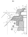
- FIG. 2 is an enlarged view of a portion A of the suspension mounting structure 1 shown in FIG.
- the suspension mounting structure 1 is disposed so as to surround a shock absorber 51 having a piston rod 50, a coil spring 52 disposed so as to surround the shock absorber 51, and the shock absorber 51.
- a vehicle strut suspension 5 having a bump stopper 53 is attached to the vehicle body 6.
- the spring seat 2 that supports the upper end 520 of the coil spring 52 and the piston rod 50 are attached to the vehicle body 6.
- An upper mount 3 for mounting and a bearing 4 disposed between the spring seat 2 and the upper mount 3 and allowing relative rotation of both are provided.
- FIG. 3 (A) and 3 (B) are a plan view and a bottom view of the spring seat 2
- FIG. 3 (C) is a BB cross-sectional view of the spring seat 2 shown in FIG. 3 (A). .
- the spring sheet 2 is formed of a high-strength synthetic resin such as polyamide resin, polypropylene resin, polyacetal resin, polybutylene terephthalate resin reinforced with glass fiber, glass powder, carbon fiber, etc.
- the sheet main body 20, a cylindrical accommodating portion 21, and a flange portion 22 are included.
- the spring seat main body 20 has an upper surface 200 on which an annular mounting surface 201 for mounting the bearing 4 is formed, and a lower surface 202 on which a support surface 203 for supporting the upper end portion 520 of the coil spring 52 is formed.
- a plurality of guide grooves 206 along the axis O are formed at equal intervals in the circumferential direction on the inner peripheral surface 205 of the mounting hole 204.
- a rotation stopper 414 (see FIG. 5), which will be described later, of the bearing 4 is inserted into the guide groove 206.
- FIG. 3 only some of the guide grooves 206 are denoted by reference numerals.
- the accommodating portion 21 is formed on the lower surface 202 of the spring seat body 20, and accommodates the upper end portion 530 of the bump stopper 53 of the strut suspension 5 (see FIG. 1).
- a plurality of protrusions 211 projecting inward are formed on the inner peripheral surface 210 of the housing portion 21 at equal intervals in the circumferential direction.
- the protrusion 211 presses and fixes the upper end 530 of the bump stopper 53 accommodated in the accommodating portion 21 inward in the radial direction.
- only some of the protrusions 211 are denoted by reference numerals.
- the flange portion 22 is formed on the outer peripheral surface 207 of the spring seat main body 20, and protrudes radially outward from an outer edge portion 310 of a cover portion 31 described later of the upper mount 3 (see FIG. 1).
- the upper surface 220 of the flange portion 22 is inclined toward the lower surface 202 of the spring seat body 20 as it goes outward in the radial direction.
- the lower surface 221 of the flange portion 22 is located on the upper surface 200 side of the spring seat main body 20 with respect to the support surface 203 of the spring seat main body 20, whereby a step surface 222 is formed between the lower surface 221 and the support surface 203.
- Line segment passing through the outer edge 223 of the vehicle, that is, high-pressure water P which is injected from the nozzle of the high-pressure car wash machine and enters the tire house of the vehicle at the time of car washing using the high-pressure car wash machine of the vehicle employing the suspension mounting structure 1 Is set to be larger than an angle ⁇ formed by the assumed injection direction and the perpendicular V.
- the angle ⁇ formed varies depending on the type and size of the vehicle that employs the suspension mounting structure 1, but falls within a range of 30 to 60 degrees in the case of a normal automobile.
- the outer diameter r of the flange portion 22 is set so that the formed angle ⁇ is at least 30 degrees, preferably 45 degrees or more, more preferably 60 degrees or more.
- an insertion hole 302 for inserting the piston rod 50 through the upper surface 300 and the lower surface 301 is formed so that the cover portion 31 and the shaft center O coincide with each other.
- An accommodation portion 303 that accommodates the bearing 4 is formed on the lower surface 301 of the upper mount body 30.
- the cover portion 31 is formed on the lower surface 301 of the upper mount body 30 so as to surround the accommodating portion 303 of the upper mount body 30, and covers the upper surface 200 of the spring seat body 20 of the spring seat 2.
- a clearance d is provided in the thrust direction with respect to the upper surface 200 of 20.
- the outer edge portion 310 of the cover portion 31 is formed in a cylindrical shape and surrounds the upper surface 200 side of the outer peripheral surface 207 of the spring seat body 200 (see FIG. 1).
- the bearing 4 is a sliding bearing, and as shown in the drawing, a cylindrical lower case 41 into which an annular upper case 40 and a piston rod 50 of a shock absorber 51 are inserted and which is rotatably combined with the upper case 40. And an annular center plate 42 and a metal washer 43 disposed between the upper case 40 and the lower case 41.
- the upper case 40 is formed of a high-strength synthetic resin such as a polyamide resin or a polypropylene resin reinforced with glass fibers, and an upper surface 400 has a mounting surface 401 that contacts the inner surface 304 of the housing portion 303 of the upper mount 3. Is formed.
- the bearing 4 is accommodated in the accommodating portion 303 of the upper mount 3 by bringing the mounting surface 401 of the upper case 40 into contact with the inner surface 304 of the accommodating portion 303 of the upper mount 3, so that the bearing 4 is accommodated in the accommodating portion 303 of the upper mount 3. Fixed to.
- a mounting hole 403 for mounting the metal washer 43 is formed through the upper surface 401 in the lower surface 402 of the upper case 40, and the upper surface 430 of the metal washer 43 is formed around the mounting hole 403 in the lower surface 402.
- An annular lower surface 404 is formed in contact with.
- the outer peripheral surface 412 of the lower case 41 is formed with a flange portion 413 that comes into contact with the mounting surface 201 of the spring seat body 20 of the spring seat 2 when the bearing 4 is mounted on the spring seat 2. Further, when the bearing 4 is mounted on the spring seat 2, the outer peripheral surface 412 is inserted into a guide groove 206 formed in the inner peripheral surface 205 of the mounting hole 204 of the spring seat body 20 of the spring seat 2.
- a plurality of stops 414 are formed at equal intervals in the circumferential direction. In FIG. 5, only some of the rotation stoppers 414 are denoted by reference numerals.
- the center plate 42 is formed of a thermoplastic elastomer having excellent sliding characteristics such as polyethylene and thermoplastic polyester elastomer, and is disposed between the annular lower surface 404 of the upper case 40 and the annular upper surface 411 of the lower case 41. As a result, the upper case 40 and the lower case 41 rotate relatively via the center plate 42.
- the metal washer 43 is disposed between the annular lower surface 404 of the upper case 40 and the upper surface 420 of the center plate 42, and the piston rod 50 of the shock absorber 51 is inserted therein.
- the metal washer 43 is formed of a steel plate such as steel or stainless steel, or a non-ferrous alloy plate such as copper alloy or titanium alloy, and a cylindrical boss portion 431 mounted on the mounting hole 403 of the upper case 40 on the upper surface 430 thereof. Is formed.
- the spring seat 2 that supports the coil spring 52 and the lower case 41 of the bearing 4 are also coil spring 52. At the same time, it rotates in the circumferential direction R.
- the upper case 40 of the bearing 4 is placed on the nut 7 screwed into the screw portion 500 of the piston rod 50 and a step surface (not shown) of the piston rod 50 formed at the root portion of the screw portion 500. The bearing 4 is held by the upper washer 3 so as not to rotate in the circumferential direction R with respect to the piston rod 50.
- the suspension mounting structure 1 allows the spring 4 to be attached to the strut suspension 5 via the coil spring 52 while allowing the bearing 4 to rotate the coil spring 52 in the circumferential direction R with respect to the upper mount 3. Support the applied load.
- the spring seat 2 has the upper surface 200 side of the outer peripheral surface 207 of the spring seat body 20 surrounded by the outer edge portion 310 of the cover portion 31 of the upper mount 3. For this reason, when a vehicle employing the suspension mounting structure 1 is washed with a high-pressure car wash machine, as shown in FIG. 2, the high-pressure water P ′ injected into the tire house from the nozzle of the high-pressure car wash machine is Even when the direction of traveling toward the (ceiling of the tire house) is changed and the clearance between the outer edge portion 310 of the cover portion 31 of the upper mount 3 and the flange portion 22 of the spring seat 2 is reached, this high-pressure water P ′ is used as the spring seat. It can be blocked by the outer peripheral surface 207 of the body 2.
- the corrosion resistance is high, and high-pressure water enters the bearing 4 disposed between the upper mount 3 and the spring seat 2 when washing with a high-pressure car wash machine. Can be prevented.
- the outer diameter r of the flange portion 22 of the spring seat 2 is a line segment passing through the outer edge end 223 of the upper surface 220 of the flange portion 22 and the lower end 311 of the outer edge portion 310 of the cover portion 31 of the upper mount 3.
- the angle ⁇ formed by L and the perpendicular V is high-pressure water P that is injected from the nozzle of the high-pressure car wash machine and enters the tire house when the vehicle employing the suspension mounting structure 1 is washed by the high-pressure car wash machine. It is set to be larger than an angle ⁇ formed by the injection direction and the perpendicular V (in the case of a normal automobile, a range of 30 to 60 degrees).
- the flange portion 22 of the spring seat 2 is such that the lower surface 221 of the flange portion 22 is located on the upper surface 200 side of the spring seat body 20 with respect to the support surface 203 of the spring seat body 20.
- the coil spring 52 contracts.
- the second coil from the upper end 520 of the coil spring 52 is more radial than the first coil. Since it bulges outward, the second coil may come into contact with the lower surface 221 of the flange portion 22.
- the thickness of the flange portion 22 is greater than the thickness of the spring seat body 20. getting thin. For this reason, when the second coil from the upper end 520 of the coil spring 52 comes into contact with the lower surface 221 of the flange 22, the flange 22 may be damaged by the pressure of the coil spring 52.
- the lower surface 221 of the flange portion 22 is located on the upper surface 200 side of the spring seat body 20 with respect to the support surface 203 of the spring seat body 20, and therefore the upper end portion 520 of the coil spring 52. The second coil can be prevented from coming into contact with the lower surface 221 of the flange portion 22, thereby preventing the flange portion 22 from being damaged by the pressure of the coil spring 52.
- the flange portion 22 of the spring seat 2 is inclined toward the lower surface 202 side of the spring seat body 20 as the upper surface 220 of the flange portion 22 goes radially outward. For this reason, when a vehicle employing the suspension mounting structure 1 is washed with a high-pressure car wash machine, as shown in FIG. 2, the high-pressure water P ′ injected into the tire house from the nozzle of the high-pressure car wash machine is Even when the direction of traveling toward the (ceiling of the tire house) is changed and the upper surface 220 of the flange portion 22 of the spring seat 2 is reached, the high-pressure water P ′ flows down from the upper surface 220 of the flange portion 22 radially outward. be able to.
- the spring seat 2 is formed on the upper surface 220 of the spring seat body 20 and has a placement surface 201 on which the bearing 4 is placed. Projecting from the upper surface 200 of the spring seat body 20 located around the placement surface 201, a step surface 208 is formed between the upper surface 200 of the spring seat body 20 located around the placement surface 201. Yes. For this reason, when a vehicle employing the suspension mounting structure 1 is washed with a high-pressure car wash machine, as shown in FIG.
- the high-pressure water P ′ injected into the tire house from the nozzle of the high-pressure car wash machine is The direction of traveling toward the ceiling of the tire house is changed to reach the gap between the outer edge portion 310 of the cover portion 31 of the upper mount 3 and the flange portion 22 of the spring seat 2 and exceed the outer peripheral surface 207 of the spring seat body 2. Even when it enters the inside, it can be blocked by the step surface 208 of the spring seat body 2, so that high-pressure water can be more reliably prevented from entering the bearing 4.
- a plurality of guide grooves 206 are formed at equal intervals in the circumferential direction on the inner peripheral surface 205 of the mounting hole 204 of the spring seat main body 20, and in accordance with this, a bearing is formed.
- a plurality of rotation stoppers 414 are formed at equal intervals in the circumferential direction.
- the present invention is not limited to this. It is sufficient that at least one guide groove 206 is formed on one of the inner peripheral surface 205 of the mounting hole 204 of the spring seat body 20 and the outer peripheral surface 412 of the lower case 41 of the bearing 4.
- the lower case 41 is prevented from rotating with respect to the mounting surface 201 of the spring seat body 20, and the lower case 41 and the spring seat body 20 are prevented from being worn by sliding between them. Can do.
- the upper end portion 520 of the coil spring 52 is directly in contact with the support surface 203 of the spring seat main body 20, but the lower surface 202 of the spring seat main body 20 or the spring seat main body.
- a cushioning material made of rubber, elastomer, or the like is provided to cover the lower surface 202 of 20 and the outer peripheral surface 212 of the accommodating portion 21, and the upper end portion 520 of the coil spring 52 is brought into contact with the support surface 203 of the spring seat body 20 through this cushioning material. May be.
- the cushioning material may be integrated with the spring seat body 20 or may be separate.
- the present invention is not limited to the strut suspension 5 and can be widely applied to suspension mounting structures for mounting a suspension having a shock absorber and a coil spring to the vehicle body 6.
Landscapes
- Engineering & Computer Science (AREA)
- Mechanical Engineering (AREA)
- General Engineering & Computer Science (AREA)
- Vehicle Body Suspensions (AREA)
- Fluid-Damping Devices (AREA)
Abstract
Description
ベアリングにより、サスペンションのピストンロッドを車体に取り付けるためのアッパーマウントに対して相対的に回動可能に配置され、当該サスペンションのコイルスプリングの上端部を支持する合成樹脂製のスプリングシートであって、
上面が前記アッパーマウントに対してスラスト方向に隙間を設けて配置され、外周面の前記上面側が前記アッパーマウントの外縁部により囲まれ、そして下面に前記コイルスプリングの上端部を支持する支持面が形成された環状のスプリングシート本体と、
前記スプリングシート本体の前記外周面に形成され、前記アッパーマウントの前記外縁部よりも径方向外方に突出したフランジと、を備えている。
ピストンロッドと、ステアリング操作によって前記ピストンロッドに対して相対的に回動するコイルスプリングと、を有するサスペンションを車体へ取り付けるためのサスペンション取付構造であって、
前記ピストンロッドを前記車体に取り付けるための円筒状のアッパーマウントと、
前記コイルスプリングの上端部を支持する上述のスプリングシートと、
前記アッパーマウントと前記スプリングシートとの間に配置されて両者の相対的な回動を許容するベアリングと、を備え、
前記アッパーマウントは、
当該アッパーマウントの下端部に形成され、前記スプリングシートの前記スプリングシート本体の前記上面を覆うように、当該スプリングシート本体の前記上面に対してスラスト方向に隙間を設けて配置されたカバー部を有し、
前記カバー部の外縁部は、
前記アッパーマウントの前記外縁部として、前記スプリングシート本体の前記外周面の前記上面側を囲んでいる。
Claims (7)
- ベアリングにより、サスペンションのピストンロッドを車体に取り付けるためのアッパーマウントに対して相対的に回動可能に配置され、当該サスペンションのコイルスプリングの上端部を支持する合成樹脂製のスプリングシートであって、
上面が前記アッパーマウントに対してスラスト方向に隙間を設けて配置され、外周面の前記上面側が前記アッパーマウントの外縁部により囲まれ、そして下面に前記コイルスプリングの上端部を支持する支持面が形成された環状のスプリングシート本体と、
前記スプリングシート本体の前記外周面に形成され、前記アッパーマウントの前記外縁部よりも径方向外方に突出したフランジと、を備えている
ことを特徴とするスプリングシート。 - 請求項1に記載のスプリングシートであって、
前記フランジの外径は、
当該フランジの上面の外縁端および前記アッパーマウントの前記外縁部の下端を通る線分と垂線とのなす角αが、前記車体のフェンダーの縁部および当該フランジの上面の外縁端を通る線分と垂線とのなす角βより大きくなるように設定されている
ことを特徴とするスプリングシート。 - 請求項2に記載のスプリングシートであって、
前記フランジの外径は、
前記なす角αが30度より大きくなるように設定されている
ことを特徴とするスプリングシート。 - 請求項1ないし3のいずれか一項に記載のスプリングシートであって、
前記フランジは、
当該フランジの下面が前記スプリングシート本体の前記支持面よりも前記スプリングシート本体の前記上面側に位置している
ことを特徴とするスプリングシート。 - 請求項1ないし4のいずれか一項に記載のスプリングシートであって、
前記フランジは、
当該フランジの上面が径方向外方に向かうにしたがい前記スプリングシート本体の前記下面側に傾斜している
ことを特徴とするスプリングシート。 - 請求項1ないし5のいずれか一項に記載のスプリングシートであって、
前記スプリングシート本体の前記上面に形成され、前記ベアリングを載置するための載置面をさらに備え、
前記載置面は、
当該載置面の周囲に位置する前記スプリングシート本体の前記上面から突出している
ことを特徴とするスプリングシート。 - ピストンロッドと、ステアリング操作によって前記ピストンロッドに対して相対的に回動するコイルスプリングと、を有するサスペンションを車体へ取り付けるためのサスペンション取付構造であって、
前記ピストンロッドを前記車体に取り付けるための円筒状のアッパーマウントと、
前記コイルスプリングの上端部を支持する請求項1ないし6のいずれか一項に記載のスプリングシートと、
前記アッパーマウントと前記スプリングシートとの間に配置されて両者の相対的な回動を許容するベアリングと、を備え、
前記アッパーマウントは、
当該アッパーマウントの下端部に形成され、前記スプリングシートの前記スプリングシート本体の前記上面を覆うように、当該スプリングシート本体の前記上面に対してスラスト方向に隙間を設けて配置されたカバー部を有し、
前記カバー部の外縁部は、
前記アッパーマウントの前記外縁部として、前記スプリングシート本体の前記外周面の前記上面側を囲んでいる
ことを特徴とするサスペンション取付構造。
Priority Applications (2)
| Application Number | Priority Date | Filing Date | Title |
|---|---|---|---|
| BR112020018069-6A BR112020018069A2 (pt) | 2018-03-06 | 2019-02-25 | Assento de mola e estrutura de montagem de suspensão |
| CN201980013793.1A CN111788407B (zh) | 2018-03-06 | 2019-02-25 | 弹簧座和悬架安装结构 |
Applications Claiming Priority (2)
| Application Number | Priority Date | Filing Date | Title |
|---|---|---|---|
| JP2018039996A JP7002366B2 (ja) | 2018-03-06 | 2018-03-06 | サスペンション取付構造 |
| JP2018-039996 | 2018-03-06 |
Publications (1)
| Publication Number | Publication Date |
|---|---|
| WO2019172004A1 true WO2019172004A1 (ja) | 2019-09-12 |
Family
ID=67846633
Family Applications (1)
| Application Number | Title | Priority Date | Filing Date |
|---|---|---|---|
| PCT/JP2019/007115 Ceased WO2019172004A1 (ja) | 2018-03-06 | 2019-02-25 | スプリングシートおよびサスペンション取付構造 |
Country Status (4)
| Country | Link |
|---|---|
| JP (1) | JP7002366B2 (ja) |
| CN (1) | CN111788407B (ja) |
| BR (1) | BR112020018069A2 (ja) |
| WO (1) | WO2019172004A1 (ja) |
Cited By (1)
| Publication number | Priority date | Publication date | Assignee | Title |
|---|---|---|---|---|
| DE102023207154A1 (de) * | 2023-07-27 | 2025-01-30 | Zf Friedrichshafen Ag | Stützlagerbaugruppe für einen Stoßdämpfer von einem Fahrzeug, Verfahren zur Herstellung der Stützlagerbaugruppe sowie Stoßdämpfer mit der Stützlagerbaugruppe |
Families Citing this family (2)
| Publication number | Priority date | Publication date | Assignee | Title |
|---|---|---|---|---|
| DE102018217666A1 (de) * | 2018-10-16 | 2020-04-16 | Aktiebolaget Skf | Aufhängungsaxiallagervorrichtung |
| JP2024079156A (ja) * | 2022-11-30 | 2024-06-11 | 住友理工株式会社 | 防振装置 |
Citations (5)
| Publication number | Priority date | Publication date | Assignee | Title |
|---|---|---|---|---|
| JP2005265155A (ja) * | 2004-03-22 | 2005-09-29 | Kayaba Ind Co Ltd | 車両用懸架装置 |
| JP2007308137A (ja) * | 2006-05-16 | 2007-11-29 | Snr Roulements | 強化シールを備える車両サスペンション停止体 |
| JP2013224137A (ja) * | 2012-04-23 | 2013-10-31 | Ab Skf | 懸架軸受装置、及び当該懸架軸受装置を装着したストラット |
| WO2014125792A1 (ja) * | 2013-02-15 | 2014-08-21 | オイレス工業株式会社 | 合成樹脂製の滑り軸受 |
| WO2018016500A1 (ja) * | 2016-07-19 | 2018-01-25 | オイレス工業株式会社 | 滑り軸受 |
Family Cites Families (6)
| Publication number | Priority date | Publication date | Assignee | Title |
|---|---|---|---|---|
| CN100497989C (zh) * | 2006-02-21 | 2009-06-10 | 东海橡胶工业株式会社 | 机动车悬架的弹簧座 |
| FR2909929B1 (fr) * | 2006-12-18 | 2009-02-20 | Snr Roulements Sa | Dispositif de butee de suspension de vehicule a etancheite renforcee |
| JP4371429B2 (ja) * | 2007-05-29 | 2009-11-25 | Ntn株式会社 | 車輪用軸受装置 |
| FR2973291B1 (fr) * | 2011-03-30 | 2016-01-08 | Ntn Snr Roulements | Butee de suspension a etancheite renforcee |
| JP5910000B2 (ja) * | 2011-11-02 | 2016-04-27 | オイレス工業株式会社 | 合成樹脂製の滑り軸受 |
| CN204003952U (zh) * | 2014-08-11 | 2014-12-10 | 温州人本汽车轴承股份有限公司 | 一种悬架减震器支柱轴承 |
-
2018
- 2018-03-06 JP JP2018039996A patent/JP7002366B2/ja active Active
-
2019
- 2019-02-25 BR BR112020018069-6A patent/BR112020018069A2/pt active Search and Examination
- 2019-02-25 CN CN201980013793.1A patent/CN111788407B/zh active Active
- 2019-02-25 WO PCT/JP2019/007115 patent/WO2019172004A1/ja not_active Ceased
Patent Citations (5)
| Publication number | Priority date | Publication date | Assignee | Title |
|---|---|---|---|---|
| JP2005265155A (ja) * | 2004-03-22 | 2005-09-29 | Kayaba Ind Co Ltd | 車両用懸架装置 |
| JP2007308137A (ja) * | 2006-05-16 | 2007-11-29 | Snr Roulements | 強化シールを備える車両サスペンション停止体 |
| JP2013224137A (ja) * | 2012-04-23 | 2013-10-31 | Ab Skf | 懸架軸受装置、及び当該懸架軸受装置を装着したストラット |
| WO2014125792A1 (ja) * | 2013-02-15 | 2014-08-21 | オイレス工業株式会社 | 合成樹脂製の滑り軸受 |
| WO2018016500A1 (ja) * | 2016-07-19 | 2018-01-25 | オイレス工業株式会社 | 滑り軸受 |
Cited By (1)
| Publication number | Priority date | Publication date | Assignee | Title |
|---|---|---|---|---|
| DE102023207154A1 (de) * | 2023-07-27 | 2025-01-30 | Zf Friedrichshafen Ag | Stützlagerbaugruppe für einen Stoßdämpfer von einem Fahrzeug, Verfahren zur Herstellung der Stützlagerbaugruppe sowie Stoßdämpfer mit der Stützlagerbaugruppe |
Also Published As
| Publication number | Publication date |
|---|---|
| JP2019152315A (ja) | 2019-09-12 |
| JP7002366B2 (ja) | 2022-01-20 |
| CN111788407A (zh) | 2020-10-16 |
| BR112020018069A2 (pt) | 2020-12-22 |
| CN111788407B (zh) | 2023-01-10 |
Similar Documents
| Publication | Publication Date | Title |
|---|---|---|
| US9400015B2 (en) | Synthetic resin-made sliding bearing | |
| US8894295B2 (en) | Suspension strut bearing | |
| US8474846B2 (en) | Thrust bearing and suspension for vehicle | |
| RU2428595C2 (ru) | Упорный подшипник скольжения и комбинированное устройство из упорного подшипника скольжения и поршневого штока с цилиндрической пружиной | |
| WO2019172004A1 (ja) | スプリングシートおよびサスペンション取付構造 | |
| US20140199007A1 (en) | Synthetic resin-made thrust sliding bearing | |
| JP7381887B2 (ja) | ストラットベアリング、及び車両のストラット式サスペンション | |
| WO2010034734A1 (en) | Bump stop and associated macpherson strut | |
| US10344799B2 (en) | Sliding bearing | |
| CN102791501A (zh) | 用于车辆的止推轴承和悬挂 | |
| KR101819143B1 (ko) | 베어링이 구비된 일체형 더스트 커버 | |
| WO2019013142A1 (ja) | スプリングシートおよび軸受装置 | |
| JP2007016972A (ja) | スラスト軸受及び車両用サスペンション | |
| CN100423961C (zh) | 车辆的悬架结构 | |
| US20180236837A1 (en) | Suspension Strut Bearing | |
| WO2019013132A1 (ja) | スプリングシートおよび軸受装置 | |
| KR102663539B1 (ko) | 차량용 스테빌라이저의 부시 장치 | |
| JP2019018628A (ja) | スプリングシートおよび軸受装置 | |
| US12618434B2 (en) | Strut bearing device and vehicle strut suspension | |
| KR20170078993A (ko) | 차량용 서스펜션 장치 | |
| US20250116297A1 (en) | Strut bearing device and vehicle strut suspension | |
| JPH01199028A (ja) | ブッシュ組立体 | |
| US20240075782A1 (en) | Suspension stop and suspension strut | |
| WO2011026759A1 (en) | Bump stop device and macpherson strut | |
| EP3282140A1 (en) | Thrust bearing for vehicles |
Legal Events
| Date | Code | Title | Description |
|---|---|---|---|
| 121 | Ep: the epo has been informed by wipo that ep was designated in this application |
Ref document number: 19764910 Country of ref document: EP Kind code of ref document: A1 |
|
| NENP | Non-entry into the national phase |
Ref country code: DE |
|
| REG | Reference to national code |
Ref country code: BR Ref legal event code: B01A Ref document number: 112020018069 Country of ref document: BR |
|
| ENP | Entry into the national phase |
Ref document number: 112020018069 Country of ref document: BR Kind code of ref document: A2 Effective date: 20200903 |
|
| 122 | Ep: pct application non-entry in european phase |
Ref document number: 19764910 Country of ref document: EP Kind code of ref document: A1 |