WO2019167653A1 - 把持装置及び産業用ロボット - Google Patents
把持装置及び産業用ロボット Download PDFInfo
- Publication number
- WO2019167653A1 WO2019167653A1 PCT/JP2019/005382 JP2019005382W WO2019167653A1 WO 2019167653 A1 WO2019167653 A1 WO 2019167653A1 JP 2019005382 W JP2019005382 W JP 2019005382W WO 2019167653 A1 WO2019167653 A1 WO 2019167653A1
- Authority
- WO
- WIPO (PCT)
- Prior art keywords
- palm
- finger
- gripping device
- gripping
- strength
- Prior art date
- Legal status (The legal status is an assumption and is not a legal conclusion. Google has not performed a legal analysis and makes no representation as to the accuracy of the status listed.)
- Ceased
Links
Images






Classifications
-
- B—PERFORMING OPERATIONS; TRANSPORTING
- B25—HAND TOOLS; PORTABLE POWER-DRIVEN TOOLS; MANIPULATORS
- B25J—MANIPULATORS; CHAMBERS PROVIDED WITH MANIPULATION DEVICES
- B25J15/00—Gripping heads and other end effectors
- B25J15/08—Gripping heads and other end effectors having finger members
Definitions
- the present invention relates to a gripping device and an industrial robot.
- a gripping device for gripping a workpiece, a palm part, a plurality of finger parts provided to protrude around the palm part and falling toward the palm part by deforming the palm part in the thickness direction
- a gripping device including a bag-shaped gripping body having a granular material housed in the gripping body (Patent Document 1).
- Patent Document 1 a gripping device
- the palm is deformed elastically so that the palm is deformed in the thickness direction and the finger is tilted toward the palm. Since this gripping device has a plurality of finger parts, it can grip a workpiece of different sizes and shapes for general use, and it can be gripped simply by reducing the pressure inside the gripping body. Since it is not necessary to press strongly against the workpiece, a flexible workpiece such as food can be gripped without being damaged.
- the gripping device of Patent Document 1 has a problem that when the grip body is ruptured due to deterioration or breakage, the granular material filled in the grip body is scattered to contaminate the workpiece. Since the granular material deteriorates due to the density change accompanying the Jamming transition, there is a problem that it cannot be used stably.
- An object of the present invention is to provide a gripping device and an industrial robot that can grip a workpiece more reliably without using a granular material.
- a gripping device is provided with a palm, a plurality of fingers that protrude around the palm, and are tilted toward the palm by deforming the palm in the thickness direction, and the finger Formed at a position surrounding the outer edge of the palm part on the opposite side of the side where the part is formed, and connected to a case, provided between the palm part and the connecting part, and provided at the outer edge of the palm part
- a high-strength portion that has a predetermined length in the thickness direction of the palm portion and is less likely to deform than the palm portion, and a function holding portion provided at a position that covers the palm portion and the finger portion.
- the industrial robot according to the present invention is provided with the gripping device.
- the high strength portion prevents the outer periphery of the palm portion from contracting, and the palm portion deforms in the thickness direction, thereby deforming the finger portion toward the palm portion and gripping the work. Therefore, the workpiece can be gripped more reliably without using powder.
- the gripping device can add another function in addition to the function of gripping the workpiece.
- a gripping device is provided with a palm, a plurality of fingers that protrude around the palm, and are tilted toward the palm by deforming the palm in the thickness direction, and the finger Formed at a position surrounding the outer edge of the palm part on the opposite side of the side where the part is formed, and connected to a case, provided between the palm part and the connecting part, and provided at the outer edge of the palm part
- a high-strength portion that has a predetermined length in the thickness direction of the palm portion and is less likely to deform than the palm portion, and a function holding portion provided at a position that covers the palm portion and the finger portion.
- the high-strength part is harder to deform than the palm part, when the inner surface side of the palm part is depressurized, the palm part deforms in the thickness direction without contracting the outer periphery. Therefore, the gripping main body is elastically deformed so that the finger part falls down toward the palm part, so that the workpiece can be gripped more reliably without using the powdery body.
- the high-strength part is formed to have higher mechanical strength than the palm part.
- the high-strength portion includes a case where it is separate from the palm portion, the finger portion, and the connection portion, and a case where it is integral.
- the high-strength part When the high-strength part is integrated with the palm part, the finger part, and the connection part, the high-strength part may be provided uniformly around the palm part or may be provided partially. Specifically, the high-strength part may be thicker than the palm part. In this case, the thickness of the high-strength portion is not limited to being uniform, and may be partially thick. The case of being partially thick includes the case of being partially in the circumferential direction of the palm part and the case of being partially in a direction parallel to the thickness direction of the palm part.
- the high strength portion may be formed of a material having higher mechanical strength than the palm portion.
- the material having high mechanical strength includes a material having the same quality as the palm but having high hardness, a material different from the palm, a case of containing an additive such as a filler, and a case of a composite material thereof.
- the high-strength portion contacts a part of the case at the proximal end.
- the high-strength portion includes a case where the base end is in surface contact with the case and a case where the base portion is in line contact.
- the proximal end preferably has a contact surface that contacts the case. When the case includes an upper case and a lower case, the upper case may contact the contact surface, or the lower case may contact the contact surface.
- the high-strength portion is a certain region from the proximal end to the distal end connected to the palm portion.
- the tip is the boundary between the high-strength part and the palm part, but is not limited to the case where it can be clearly visually recognized.
- the tip is preferably a fulcrum when the palm is deformed in the thickness direction.
- the function holding part includes a form covering a functional part provided on at least a part of the surface of the palm part and the finger part.
- the functional part includes a dynamic part that shows a reaction by an external action and a static part that maintains a state regardless of an external action.
- the function holding part includes the case where it is formed integrally with the gripping body.
- the function holding part may have a form to which a function is given by surface treatment.
- the surface treatment includes a case where another member is fixed to the surface when the surface property of the function holding portion is modified.
- FIG. 1 shows a configuration of an industrial robot 12 to which the gripping device 10A according to the present embodiment is applied.
- the industrial robot 12 is an orthogonal robot, and includes a rail 14, a moving body 16 that moves along the rail 14, and an air cylinder 18 that is fixed to the moving body 16.
- the rail 14 is provided so as to be movable in the Y-axis direction in the drawing.
- the air cylinder 18 has a cylinder tube 19 and a piston rod 20 provided so as to be able to advance and retract with respect to the cylinder tube 19.
- the cylinder tube 19 is provided with pipes 21 and 22. By supplying and exhausting gas through the pipes 21 and 22, the piston rod 20 can advance and retreat with respect to the cylinder tube 19.
- a gripping device 10 ⁇ / b> A is provided at the tip of the piston rod 20 via an adapter plate 23.
- the adapter plate 23 is fixed to the tip of the piston rod 20 by a bolt (not shown).
- the industrial robot 12 can grip the workpiece W placed on the horizontal base 26 with the gripping device 10A and move in the X-axis, Y-axis, and Z-axis directions.
- the gripping device 10 ⁇ / b> A includes a grip body 28 ⁇ / b> A connected to the piston rod 20 and a function holding portion 71 ⁇ / b> A.
- the grip body 28A can be formed of a material having airtightness and elasticity, for example, natural rubber or synthetic rubber.
- the hardness measured according to the JIS K6253 durometer hardness test (type A) of the gripping body 28A is preferably about 60 to 90.
- the gripping main body 28 ⁇ / b> A has a palm portion 30 and a plurality of finger portions 32 provided so as to protrude around the palm portion 30.
- the palm 30 has a substantially disk shape.
- the finger portions 32 are formed integrally with the palm portion 30, and five finger portions 32 are provided radially so as to surround the palm portion 30. A predetermined interval is formed between the finger portions 32.
- the finger portion 32 has an inner surface 31 formed integrally with the palm portion 30.
- the external shape of the finger part 32 can be selected as appropriate, and may be, for example, a cylinder, a cone, a truncated cone, a triangular prism, a quadrangular prism, a triangular pyramid, a quadrangular pyramid, a quadrangular pyramid, a rectangular parallelepiped, or the like.
- the finger part 32 is comprised by the same shape. Note that the plurality of finger portions 32 need not all have the same shape, and may have different shapes.
- a connection portion 38 is integrally formed at a position surrounding the outer edge of the palm portion 30 on the side opposite to the side where the finger portion 32 is formed.
- the connecting portion 38 has a cylindrical shape, and in the case of this figure, has a circular opening at the upper end.
- the gripping main body 28 ⁇ / b> A has an outer peripheral surface 34 curved in a direction protruding outward from the palm portion 30 toward the connection portion 38.
- the finger part 32 is solid.
- the material of the finger part 32 may be the same material as the other parts (the palm part 30 or the connection part 38) or a different material, and need not be even more uniform. Additives such as composite materials and fillers combining different materials May be included.
- the opening of the gripping main body 28 ⁇ / b> A is sealed by a case 36 inserted into the connection portion 38.
- the case 36 is detachably connected to the detachable portion 64.
- the detachable part 64 is a one-touch joint, and one end is connected to the adapter plate 23 provided at the tip of the piston rod 20 and the other end is connected to the joint 62 of the case 36.
- the detachable portion 64 is connected when the joint 62 is inserted in the insertion direction, and the connection is released when the release portion is pushed in the insertion direction.
- the detachable part 64 is not limited to a one-touch joint, and may be a joint connected to the joint 62 by a screw.
- the grip body 28A includes a high-strength portion 42 that is less likely to deform in the thickness direction than the palm portion 30 between the connection portion 38 and the palm portion 30.
- the high-strength portion 42 is disposed in the internal space of the palm portion 30 of the grip body 28A.
- the high-strength portion 42 holds the grip body 28A so that the outer periphery of the palm portion 30 other than the palm portion 30, that is, the outer periphery of the palm portion 30 does not contract.
- the material of the high-strength portion 42 is sufficient if it does not deform under the reduced pressure of the grip body 28A, and for example, a hard resin or metal can be used.
- the material of the high-strength portion 42 is not necessarily uniform, and may be a composite material in which different materials are combined.
- the high-strength portion 42 shown in this figure is a frame-like member having a guide hole 47 that receives the deformed palm portion 30 and a curved portion 46 outside the tip of the guide hole 47 in the axial direction on the finger portion 32 side.
- the high-strength portion 42 is a cylindrical member and is tapered toward the tip as a whole.
- a bending portion 46 is provided on the finger portion 32 side of the high strength portion 42.
- the curved portion 46 has a convex shape toward the outside.
- the guide hole 47 is preferably the center of the high-strength portion 42 corresponding to the palm portion 30 and has an inner diameter that is substantially the same as that of the palm portion 30.
- the ratio of the outer diameter D to the guide hole 47 inner diameter d is preferably 1.0: 0.98 to 1.0: 0.6.
- the outer diameter D of the high-strength portion 42 is 80 mm and the inner diameter d is in the range of 48 to 78 mm, the finger 32 is elastically deformed more reliably toward the center of the palm 30.
- the finger-side tip of the high-strength portion 42 is located on the outer side in the radial direction from the center position of the base end of the finger portion 32 in plan view. That is, when the length of the finger portion 32 in the radial direction is L, the tip on the finger portion side of the high strength portion 42 is the finger portion 32 at a position where the distance T from the inside of the finger portion 32 is L / 2 or more. It is preferable to contact the proximal end.
- the function holding unit 71A includes a thin-skinned cover unit 68A that covers the palm unit 30 and the finger unit 32, and a display unit 70 as a functional unit provided between the cover unit 68A and the surface of the gripping main body 28A.
- the material of the cover portion 68A can be the same material as the palm portion 30 or the finger portion 32, a different material, or an elastic material such as resin, and does not need to be uniform, such as a composite material combining different materials, a filler, etc. Additives may be included.
- the cover portion 68A according to the present embodiment is a transparent material or a material having a transparency that allows the display unit 70 to be visually recognized from the outside. For example, silicone can be used.
- the cover portion 68A covers the entire outer periphery of the grip main body 28A, and is fixed to the case 36 by a band 65 wound around the outer periphery of the connection portion 38 together with the grip main body 28A.
- the display unit 70 is provided on the surface of the gripping main body 28A.
- the display unit 70 is provided in at least one of the palm unit 30 and the finger unit 32. In the case of this figure, the display unit 70 is provided on the finger unit 32.
- the display unit 70 includes characters, symbols, scales, symbols, and the like formed by printing such as ink jet or stamping.
- the cover unit 68A covers the display unit 70.
- the display unit 70 is applied with a company name, a product name, a product number, a logo, and the like. For example, by providing a scale as the display unit 70 on the finger unit 32, the positional relationship with the workpiece W can be easily confirmed visually.
- the desorption part 64 is provided with an air supply / exhaust port 24 on its peripheral surface.
- the air supply / exhaust port 24 is connected to one end of the pipe.
- the other end of the pipe is connected to a vacuum pump via a three-way valve, for example.
- the three-way valve has a vacuum port, a supply / exhaust port, and an atmosphere release port, and the vacuum port is connected to the vacuum pump, the supply / exhaust port is connected to the gripping device 10A, and the atmosphere release port is connected to the outside.
- gas flows from the inside of the gripping main body 28A to the outside and from the outside of the gripping main body 28A.
- the detachable portion 64 is fixed to the adapter plate 23 by screwing a bolt into the adapter plate 23 through a mounting hole (not shown) provided on the top surface.
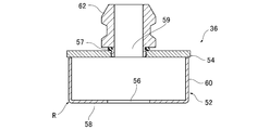
- the case 36 is preferably made of a metal such as stainless steel or a hard resin such as plastic, and has a lower case 52 and an upper case 54.
- the lower case 52 includes a bottom portion 58 having a through hole 56 at the center, and a cylindrical portion 60 formed integrally with the outer edge of the bottom portion 58.
- the outer edge R of the bottom surface which is the tip surface of the lower case 52, is chamfered.
- the chamfering can be applied by cutting the outer edge of the bottom surface into a square surface or a round surface.
- the size of the chamfering process is preferably small in order to prevent the connecting portion 38 from being locally deformed in the thickness direction.
- the upper case 54 is a disk-shaped member, and has a through hole 59 provided so as to penetrate in the thickness direction and a joint 62 communicated with the through hole 59.
- the joint 62 is screwed to the upper case 54 via a seal material 57.
- the joint 62 is connected to the detachable portion 64 by one touch.
- the lower case 52 and the upper case 54 are integrated at the upper end of the cylindrical portion 60 via a seal material (not shown).
- a method of manufacturing the gripping device 10A will be described with reference to FIG.
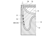
- a mold 72 including a lower mold 73 having a concave portion having the shape of the finger portion 32 and a nest 74 having a convex portion having a shape of the internal space is used.
- a grip body 28A formed in advance with a predetermined resin material is disposed at a predetermined position.
- a display unit 70 is formed in advance on the surface of the gripping main body 28A.
- the insert 74 is attached to the lower mold 73.
- a resin material forming the cover portion 68A is filled into a space 77 surrounded by the lower die 73 and the gripping main body 28A from the injection hole 76 provided in the upper die 75.
- the mold 72 is removed to obtain the gripping device 10A in which the cover portion 68A is provided on the surface of the gripping main body 28A.
- the operation and effect of the industrial robot 12 provided with the gripping device 10A configured as described above will be described.
- the conditions shown below are an example.
- the industrial robot 12 has the origin when the piston rod 20 is retracted into the cylinder tube 19 and the air cylinder 18 is contracted.
- the pressure in the gripping main body 28A is atmospheric pressure in the initial state. That is, the three-way valve is in a state where the vacuum port is shut off and the supply / exhaust port is connected to the atmosphere release port.
- the industrial robot 12 positions the gripping device 10A on the vertical line of the workpiece W placed on the base 26 as the moving body 16 moves along the rail 14 (FIG. 1). Next, the industrial robot 12 extends the air cylinder 18 until the finger portion 32 reaches the side surface of the workpiece W by the piston rod 20 advancing from the cylinder tube 19.
- the three-way valve is switched to a state where the air release port is shut off and the air supply / exhaust port is connected to the vacuum port.
- the gripping device 10A sucks the gas in the gripping main body 28A through the pipe, and reduces the pressure in the gripping main body 28A to, for example, ⁇ 0.03 MPa or less.
- the grip body 28A maintains a state in which the shape of the outer peripheral surface 34 of the palm 30 is held by the high-strength portion 42. Then, the palm part 30 is deformed in the thickness direction so as to be sucked into the guide hole 47 of the high-strength part 42 (FIG. 5). As the palm portion 30 is deformed in the thickness direction, the inner surface 31 of the finger portion 32 is pulled toward the center of the palm portion 30. Then, the finger part 32 is elastically deformed so as to fall toward the palm part 30. Thereby, as for the finger
- the gripping device 10A grips the workpiece W by reducing the pressure inside the gripping main body 28A.
- the gripping device 10A exhibits a gripping force according to the pressure in the gripping body 28A. That is, the gripping force of the gripping device 10A increases as the pressure in the gripping main body 28A decreases.
- the industrial robot 12 can lift the workpiece W from the base 26 by retracting the piston rod 20 into the cylinder tube 19 and contracting the air cylinder 18. Furthermore, the industrial robot 12 can move the workpiece W freely in the horizontal direction by moving the moving body 16 along the rail 14 or moving the rail 14 in the Y-axis direction.
- the industrial robot 12 After moving to a desired location, the industrial robot 12 extends the air cylinder 18 until the workpiece W comes into contact with the base 26 by the piston rod 20 advancing from the cylinder tube 19.
- the three-way valve is switched to a state in which the vacuum port is shut off and the supply / exhaust port is connected to the atmosphere release port.
- the gas flows into the grip body 28A from the atmosphere release port through the pipe.
- the palm 30 As the pressure in the gripping main body 28A returns to atmospheric pressure, the palm 30 is pushed out of the guide hole 47 and returns to its original state.
- the finger part 32 opens and the work W is released.
- the industrial robot 12 separates the gripping device 10 ⁇ / b> A from the workpiece W by retracting the piston rod 20 into the cylinder tube 19 and contracting the air cylinder 18. As described above, the industrial robot 12 can move to a desired position by gripping the workpiece W placed on the base 26 with the gripping device 10A.
- the grip body 28A has the finger portion 32 and the high-strength portion 42, so that the workpiece W can be gripped more reliably without using powder. Since the gripping device 10A does not use powder, even if the gripping main body 28A ruptures, the workpiece W is not contaminated.
- the shape of the finger part 32 is maintained not only when the tip of the finger part 32 is downward, but also when the finger part 32 is laterally or upward. Therefore, the gripping device 10A can not only lift the workpiece W on the base 26 but also grip the workpiece W suspended on a vertical wall surface or ceiling. Since the finger portion 32 has higher rigidity than the powder after the jamming transition, the finger W can be gripped more reliably.
- the gripping device 10A can grip the workpiece W by depressurizing the gripping main body 28A and reliably deforming the palm portion 30 in the thickness direction, so there is no need to press the gripping main body 28A against the workpiece W. Accordingly, the gripping device 10A can grip a soft work W such as food without being crushed, and thus can prevent the work W from being damaged.
- the grip body 28A can change the deformation amount and grip force of the finger portion 32 depending on the degree to which the inside is depressurized. Accordingly, the gripping device 10A can change the gripping force in accordance with the size and hardness of the workpiece W, so that versatility can be improved. Since the palm portion 30 is deformed in the thickness direction so as to be sucked into the guide hole 47, the finger portion 32 is deformed to an acute angle toward the palm portion 30. Therefore, the gripping device 10A can grip a smaller workpiece W.
- the finger portion 32 Since the finger portion 32 is deformed in the thickness direction while the palm portion 30 is in contact with the bending portion 46 because the bending portion 46 is formed in the high-strength portion 42, the finger portion 32 is continuous and loose. Transforms into Therefore, the gripping device 10A can grip the workpiece W softly. Incidentally, in the gripping device in which the bending portion is not formed in the high strength portion, the finger portion is deformed so as to buckle.
- the gripping apparatus 10A includes the function holding unit 71A, so that in addition to the function of gripping the workpiece W, another function, in the case of this embodiment, a display function by the display unit 70 can be added.
- the display unit 70 provided on the surface of the gripping main body 28A can be seen from the outside through the cover unit 68A.
- the gripping device 10 ⁇ / b> A can prevent the workpiece W from being contaminated due to the display unit 70 by including the cover unit 68 ⁇ / b> A.
- the display unit 70 is covered with the cover unit 68 ⁇ / b> A, thereby preventing wear. Accordingly, the gripping device 10A can maintain the display unit 70 for a long period of time.
- the function holding unit 71B of the gripping device 10B shown in FIG. 6 detects breakage of the gripping main body 28A.
- the function holding part 71 ⁇ / b> B includes an electric wire 78 as a functional part provided on the surface of the finger part 32 and a cover part 68 ⁇ / b> B that covers the electric wire 78.
- an insulator such as vinyl chloride is coated on a strand made of a copper alloy or the like.
- the electric wire 78 is wound around the finger portion 32 in a spiral shape.
- a voltage is applied to the electric wire 78, and a current flowing through the electric wire is detected by a detector (not shown).
- the cover portion 68B according to this modification need not be made of a transparent material or a material having such a transparency that the electric wires 78 can be visually recognized from the outside.
- breakage such as a crack occurs due to the impact from the outside on the gripping main body 28A
- the electric wire 78 at the breakage point is also broken.
- no current flows through the electric wire 78.
- the gripping device 10 ⁇ / b> B can monitor the breakage of the finger portion 32 by detecting the current flowing through the electric wire 78. Since the gripping device 10B includes the function holding unit 71B, it is possible to obtain the same effect as in the above embodiment.
- the function unit may apply a load sensor or a temperature sensor.
- a load sensor for example, a pressure sensitive sensor disclosed in JP-A-2017-72472 can be used.
- the temperature sensor a commercially available sensor such as a thermocouple can be used.
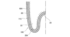
- the function holding unit 71C of the gripping device 10C shown in FIG. 7 detects changes in temperature, pressure, ultraviolet irradiation amount, and the like.
- the function holding unit 71 ⁇ / b> C includes a sensitive layer 80 as a functional unit formed of a material whose color changes depending on changes in temperature, pressure, ultraviolet irradiation amount, and the like, and a cover portion 68 ⁇ / b> A that covers the sensitive layer 80.
- the sensitive layer 80 is provided on at least a part of the palm part 30 and the finger part 32.
- the sensitive layer 80 is more preferably provided so as to cover the entire palm portion 30 and the finger portion 32. Since the gripping device 10C includes the function holding unit 71C, it is possible to obtain the same effect as in the above embodiment.
- the gripping device 10 ⁇ / b> C can visually recognize the color of the sensitive layer 80 that changes due to changes in temperature, pressure, ultraviolet irradiation amount, and the like from the outside.
- the gripping device 10C can visualize changes in temperature, pressure, ultraviolet irradiation amount, and the like.
- the function holding portion 71D shown in the figure is a layered portion including a certain region in the thickness direction of the surface of the gripping main body 28A.
- the function holding unit 71D is formed by performing a predetermined surface treatment on the surface of the gripping main body 28A.
- the surface treatment is applied to at least one of the inner surface side 82 of the palm portion 30 and the finger portion 32 and the outer surface side 84 of the finger portion 32.
- the surface treatment includes a case where the inner surface side 82 and the outer surface side 84 are the same and different cases.
- the main purpose of the surface treatment applied to the inner surface side 82 is to improve the adhesion between the finger portion 32 and the workpiece W.
- the main purpose of the surface treatment applied to the outer surface side 84 is to improve the cleanability.
- the surface treatment includes, for example, a mirror finish treatment, a matte finish treatment, a treatment for forming a fine uneven pattern having a height of about several millimeters (so-called basis weight pattern), a plasma treatment, and the like.
- the basis weight pattern can be formed by transferring the basis weight to the surface of the grip body 28A using a canvas or a mold when the grip body 28A is formed.
- the uneven pattern may be formed by embossing on the surface of the produced gripping body 28A.
- the uneven pattern for example, in a plan view, including a case of a circle, an ellipse, a triangle, a quadrangle, and an indeterminate shape, a protrusion, a recess, and a frame shape having the above shape Including protrusions and combinations thereof.
- the concavo-convex pattern may be a shape partitioned in accordance with the deformation of the palm and the finger.
- the uneven pattern may be, for example, an elliptical protrusion having elasticity and formed of a polyvinyl chloride foam.
- the function holding portion 71D may be formed by adhering a non-slip member to the surface of the gripping main body.
- a sheet-like member or a carbon nanotube may be used as the anti-slip member.
- the surface of the gripping main body 28A can be brought into a state with a high chemical bonding force, and adhesion to a work such as resin, metal, glass, etc. can be improved.
- a fluorine-based gas By performing plasma treatment using a fluorine-based gas, water repellency can be imparted to the surface of the gripping main body 28A.
- a porous fine structure similar to the surface of a lotus leaf may be formed on the surface of the grip body 28A.
- the lotus effect includes, for example, self-cleaning and water repellency.
- the function holding unit 71D is not limited to the case of directly forming the gripping main body 28A on the surface thereof, and the surface of the cover unit shown in the embodiment may be surface-treated.
- the function holding portion 71E of the gripping device 10E shown in FIG. As for the groove
- FIG. The function holding unit 71E can increase the frictional force in the width direction (lateral direction in the drawing) of the workpiece W and the finger unit 32.
- the function holding portion 71E can efficiently remove the liquid from between the finger portion 32 and the workpiece W even when the inner surface 31 is wetted by the liquid flowing into the groove 85. Therefore, the gripping device 10E can grip the workpiece W more reliably even when the inner surface 31 of the finger 32 is wetted by the liquid.
- a vertical groove (not shown) for connecting the grooves 85 may be formed.
- the function holding portion 71F of the gripping device 10F shown in FIG. 10 includes a holding portion main body 83 protruding from the tip of the finger portion 32 in the axial direction of the finger portion 32, and a plurality of protrusions 86 provided on the surface of the holding portion main body 83. Is provided.
- the projections 86 shown in the figure are annular so as to surround the periphery of the finger part 32, and a plurality of (four in the case of this figure) are provided at predetermined intervals in the axial direction of the holding part main body 83. It has been.
- the distal end of the finger part 32 is located at the proximal end of the holding part main body 83.
- the protrusion 86 is not limited to an annular shape, and may be a columnar shape, a prismatic shape, a conical shape, or the like.
- a gripping apparatus is different from the first embodiment in that the high-strength portion includes a grip body that is integral with the palm portion, the finger portion, and the connection portion.
- the same components as those in the first embodiment are denoted by the same reference numerals, and description thereof is omitted.
- a gripping main body 28 ⁇ / b> C shown in FIG. 11 includes a palm portion 30 and a plurality of finger portions 32 provided to protrude around the palm portion 30.
- the grip body 28 ⁇ / b> C includes a high-strength portion 94 that is less likely to deform in the thickness direction than the palm portion 30 between the connection portion 38 and the palm portion 30.
- the high strength portion 94 is formed integrally with the palm portion 30 and the connection portion 38.
- the high-strength portion 94 has a proximal end 96 that contacts the lower case 52, and a distal end 97 that is separated from the proximal end 96 toward the finger portion 32 and connected to the palm portion 30.
- the high-strength portion 94 is harder to deform than the palm portion 30, but is not a perfect rigid body and is microscopically deformed with the base end 96 as a fulcrum toward the center of the palm portion 30.
- the base end 96 is provided at a position away from the outer edge of the palm 30 in the thickness direction of the palm 30, that is, at a position away from the palm 30 to the upper opening side of the connecting portion 38.
- the base end 96 has a contact surface that contacts the outer peripheral portion of the bottom surface of the case 36.
- the high-strength portion 94 has an inner peripheral surface 95 in contact with the guide space 40 on the center side of the palm portion 30 continuous with the contact surface.
- the inner side of the palm portion 30 has a substantially flat inner surface 48 and a curved surface 50 that is provided around the inner surface 48 and protrudes outward.
- the inner peripheral surface 95 and the inner surface 48 of the palm 30 are connected by a curved surface 50.
- the tip 97 of the high strength portion 94 is disposed between the inner peripheral surface 95 and the curved surface 50.
- the tip 97 serves as a fulcrum when the palm 30 is deformed in the thickness direction.
- the high-strength portion 94 is formed in accordance with the shape of the connection portion 38 so as to surround the palm portion 30.
- the contact surface is the upper surface of the high-strength portion 94.
- the outer peripheral portion of the bottom surface of the case 36 contacts the contact surface of the high strength portion 94.
- the gripping device 10G can obtain the same effects as those of the first embodiment by including the function holding unit 71A.
- the high-strength portion 94 is formed integrally with the palm portion 30 and the finger portion 32, and deforms microscopically in accordance with the deformation of the palm portion 30 in the thickness direction. Thereby, the finger part 32 is continuously and gently deformed by the deformation of the palm part 30. Therefore, the gripping device 10G can grip the workpiece W softly. Incidentally, in the gripping main body that does not have the high strength portion 94, the finger portion is deformed so as to buckle.
- the grip body 28C is formed with the palm portion 30, the finger portion 32, the high-strength portion 94, and the connection portion 38 as one body, so that the number of parts and the number of manufacturing steps can be reduced. Since the palm portion 30 and the high-strength portion 94 to which more load is applied during decompression are integrally formed, the gripping main body 28C can be prevented from being damaged and the durability can be improved.
- the high-strength portion may be a plurality of strips provided at positions corresponding to the finger portions.
- the high-strength portion is evenly arranged at a position around the palm portion and corresponding to the base end of the finger portion.
- the high-strength portion has a contact surface on the upper surface and an inner peripheral surface on the inner surface on the palm portion side.
- the tip of the high strength part is disposed between the inner peripheral surface and the curved surface.
- the high-strength portion may be a plurality of annular convex portions arranged at predetermined intervals in parallel with the thickness direction of the palm portion.
- the upper surface of the convex portion that is located farthest from the palm is the contact surface.
- the inner surface on the palm side of the convex portion is the inner peripheral surface.
- the high-strength portion may be a plurality of ridges whose longitudinal direction is the thickness direction of the palm portion.
- the ridges are arranged around the palm portion with a predetermined interval.
- the upper surface of the ridge is the contact surface, and the inner surface on the palm side is the inner peripheral surface.
- the high-strength part may be formed of a material having higher mechanical strength than the palm part.
- the high-strength part can be obtained by integrally molding the finger part and the palm part by insert molding.
- the present invention is not limited to this.
- the number of finger portions may be two or three.
- an example of an orthogonal robot is shown as the industrial robot 12, but the present invention is not limited to this, and can be applied to a SCARA robot, a vertical articulated robot, and the like.
- the gripping device can grip the workpiece W and maintain the gripped state even when the industrial robot rotates about the X axis, the Y axis, and the Z axis.
- the gripping device may be provided in the hydraulic cylinder.
- the gripping device may be provided with a nail portion on the finger portion.
- a plate-shaped member made of synthetic resin, a conical member, or a sac-shaped member can be used for the claw portion.
- the case may be provided with a camera for photographing the workpiece W, a weigh scale for measuring the weight of the gripped workpiece W, a proximity sensor for measuring the distance between the workpiece W and the gripping main body, and the like.
- the camera or the like may be fixed to a bracket fixed between the piston rod 20 and the adapter plate 23.
- the adapter plate 23 may have a shape having a bracket.
- the grip body may be rectangular in plan view.
- two pairs of finger portions are provided along the long side of the palm portion, and a plurality of pairs are provided on both sides of the palm portion.
- the palm is deformed in the thickness direction, the inner surface of the finger is pulled toward the center of the palm.
- the finger part is elastically deformed so as to fall down toward the palm part.
- the finger part is elastically deformed so as to fall toward the opposing long side. Therefore, the gripping device including the gripping body can easily grip a long member such as a cylindrical shape or a prismatic shape.
- the finger part may have an elastic part inside.
- the elastic part is filled in the finger part and has the shape of the finger part. As long as the shape of the elastic portion is inserted into the finger portion of the gripping body and can maintain a certain shape, there may be a slight gap between the inner surface of the finger portion.
- the material of the elastic part is preferably resin or rubber.
- the material of the elastic part is not necessarily uniform, and may be a composite material combining different materials.
- the elastic portion may include an additive such as a filler.
- the elastic part is preferably arranged so that there is no gap between the inner surface of the finger part.
Landscapes
- Engineering & Computer Science (AREA)
- Robotics (AREA)
- Mechanical Engineering (AREA)
- Manipulator (AREA)
Abstract
粉粒体を用いず、より確実にワークを把持することができる把持装置及び産業用ロボットを提供する。掌部30と、前記掌部30の周囲に突出して設けられ、前記掌部30を厚さ方向に変形させることにより前記掌部30に向かって倒れる複数の指部32と、前記指部32が形成された側と反対側の、前記掌部30の外縁を囲む位置に形成され、ケース36に接続される接続部38と、前記掌部30と前記接続部38の間に設けられ、前記掌部30の外縁から当該掌部30の厚さ方向に所定の長さを有し、前記掌部30より変形しにくい高強度部42と、前記掌部30及び前記指部32を覆う位置に設けられた機能保持部71Aとを備える。
Description
本発明は、把持装置及び産業用ロボットに関する。
ワークを把持することを目的とした把持装置として、掌部と、掌部の周囲に突出して設けられ、前記掌部を厚さ方向に変形させることにより掌部に向かって倒れる複数の指部と、把持本体内に収容された粉粒体とを有する袋状の把持本体を備えた把持装置が開示されている(特許文献1)。当該把持装置は、把持本体内を減圧することにより、掌部が、厚さ方向に変形し、指部が掌部へ向かって倒れるように弾性変形する。この把持装置は、複数の指部を有するため、サイズや形状が異なるワークを汎用的に把持することができ、把持本体内を減圧するのみで把持できるので制御が単純であり、また把持本体をワークに強く押し付ける必要もないため、食品のような柔軟なワークを傷めずに把持することができる。
しかしながら、上記特許文献1の把持装置は、把持本体が劣化や破損などによって破裂した場合、把持本体内に充填された粉粒体が飛散し、ワークを汚染してしまう、という問題がある。粉粒体は、Jamming転移に伴う密度変化によって劣化するので、安定的に使用することができないという問題がある。
本発明は、粉粒体を用いず、より確実にワークを把持することができる把持装置及び産業用ロボットを提供することを目的とする。
本発明に係る把持装置は、掌部と、前記掌部の周囲に突出して設けられ、前記掌部を厚さ方向に変形させることにより前記掌部に向かって倒れる複数の指部と、前記指部が形成された側と反対側の、前記掌部の外縁を囲む位置に形成され、ケースに接続される接続部と、前記掌部と前記接続部の間に設けられ、前記掌部の外縁から当該掌部の厚さ方向に所定の長さを有し、前記掌部より変形しにくい高強度部と、前記掌部及び前記指部を覆う位置に設けられた機能保持部とを備える。
本発明に係る産業用ロボットは、上記把持装置が設けられている。
本発明によれば、高強度部が掌部の外周が収縮するのを防ぐことで、掌部が厚さ方向に変形することにより、指部を掌部に向かって変形させてワークを把持することができるので、粉体を用いず、より確実にワークを把持することができる。把持装置は、機能保持部を備えることによって、ワークを把持するという機能に加え、別の機能を追加することができる。
本発明に係る把持装置は、掌部と、前記掌部の周囲に突出して設けられ、前記掌部を厚さ方向に変形させることにより前記掌部に向かって倒れる複数の指部と、前記指部が形成された側と反対側の、前記掌部の外縁を囲む位置に形成され、ケースに接続される接続部と、前記掌部と前記接続部の間に設けられ、前記掌部の外縁から当該掌部の厚さ方向に所定の長さを有し、前記掌部より変形しにくい高強度部と、前記掌部及び前記指部を覆う位置に設けられた機能保持部とを備える。
高強度部が掌部より変形しにくいので、掌部の内面側を減圧した場合、掌部は、外周が収縮せず厚さ方向に変形する。したがって把持本体は、指部が掌部に向かって倒れるように弾性変形するので、粉粒体を用いず、より確実にワークを把持することができる。
高強度部は、掌部に比べ、機械的強度が高くなるように形成されている。高強度部は、掌部、指部、及び接続部と別体である場合と、一体である場合を含む。
高強度部が、掌部、指部、及び接続部と一体である場合は、掌部の周囲において一様に設けられていてもよいし、部分的に設けられていてもよい。具体的には、高強度部は、掌部に比べて厚肉としてもよい。この場合、高強度部の厚さは、一様である場合に限らず、部分的に厚肉としてもよい。部分的に厚肉である場合とは、掌部の周方向に部分的である場合と、掌部の厚さ方向に平行な方向に部分的である場合とを含む。高強度部は、掌部に比べて機械的強度の高い材料で形成してもよい。機械的強度の高い材料は、掌部と同質であるが硬度が高い材料の場合、掌部と異種材料の場合、フィラーなどの添加物を含む場合、それらの複合材の場合を含む。高強度部は、基端においてケースの一部と接触する。高強度部は、基端においてケースと面接触する場合、及び線接触する場合を含む。基端は、ケースと接触する接触面を有するのが好ましい。ケースは、上ケースと下ケースとを備える場合、上ケースが接触面と接触してもよく、下ケースが接触面と接触してもよい。高強度部は、基端から、掌部と接続される先端までの一定の領域である。先端は、高強度部と掌部の境界であるが、明確に視認できる場合に限られない。先端は、掌部が厚さ方向へ変形する場合の支点になるのが好ましい。
機能保持部は、前記掌部及び前記指部の少なくとも一部の表面に設けられた機能部を覆っている形態を含む。機能部は、外部からの働きかけによって反応を示す動的なものと、外部からの作用によらず状態が維持される静的なものとを含む。
機能保持部は、把持本体に一体に形成されている場合を含む。機能保持部は、表面処理によって機能が付与されている形態でもよい。表面処理は、機能保持部の表面性状を改質する場合、他の部材が表面に固定される場合を含む。
1.第1実施形態
以下、図面を参照して本発明の実施形態について詳細に説明する。
(全体構成)
図1に、本実施形態に係る把持装置10Aを適用した産業用ロボット12の構成を示す。産業用ロボット12は、直交ロボットであって、レール14と、レール14に沿って移動する移動体16と、移動体16に固定されたエアシリンダー18とを備える。レール14は、図中Y軸方向に移動可能に設けられている。
以下、図面を参照して本発明の実施形態について詳細に説明する。
(全体構成)
図1に、本実施形態に係る把持装置10Aを適用した産業用ロボット12の構成を示す。産業用ロボット12は、直交ロボットであって、レール14と、レール14に沿って移動する移動体16と、移動体16に固定されたエアシリンダー18とを備える。レール14は、図中Y軸方向に移動可能に設けられている。
エアシリンダー18は、シリンダーチューブ19と、シリンダーチューブ19に対し進退可能に設けられたピストンロッド20とを有する。シリンダーチューブ19には、配管21,22が設けられている。当該配管21,22を通じて、気体が給排気されることにより、ピストンロッド20がシリンダーチューブ19に対し進退可能となっている。ピストンロッド20の先端には、アダプタプレート23を介して把持装置10Aが設けられている。アダプタプレート23は、図示しないボルトによってピストンロッド20の先端に固定されている。
産業用ロボット12は、水平な基台26上に置かれたワークWを、把持装置10Aで把持すると共に、X軸、Y軸、及びZ軸方向に移動することができる。
図2に示すように、把持装置10Aは、ピストンロッド20に連結された把持本体28Aと、機能保持部71Aとを備える。把持本体28Aは、気密性と弾性とを有する材料、例えば、天然ゴムや、合成ゴムなどで形成することができる。把持本体28AのJIS K6253のデュロメータ硬さ試験(タイプA)に準じて測定した硬度は、60~90程度であるのが好ましい。
図2に示すように把持本体28Aは、掌部30と、掌部30の周囲に突出して設けられた複数の指部32とを有する。掌部30は略円盤状をなしている。指部32は、掌部30と一体に形成されており、掌部30を囲むように放射状に5個設けられている。指部32同士の間には、所定の間隔が形成されている。指部32は、内面31が掌部30と一体に形成されている。指部32の外形形状は、適宜選択することができ、例えば、円柱、円錐、円錐台、三角柱、四角柱、三角錐、四角錐、四角錐台、直方体などでもよい。本実施形態の場合、指部32は、同一形状で構成されている。なお複数の指部32は、全て同一形状である必要はなく、形状が異なっていてもよい。
把持本体28Aは、指部32が形成された側と反対側の、掌部30の外縁を囲む位置に接続部38が一体に形成されている。接続部38は筒状であって、本図の場合、上端に円形の開口を有する。把持本体28Aは、掌部30から接続部38に向かって外側に突出する向きに湾曲した外周面34を有する。指部32は、中実である。指部32の材質は、その他の部分(掌部30や接続部38)と同じ材質、または異なる材質でもよく、さらに均一である必要はなく、異種材料を組み合わせた複合材、フィラーなどの添加物を含んでもよい。把持本体28Aの開口は、接続部38に挿入されたケース36によって密閉されている。ケース36は、脱着部64に着脱自在に連結される。脱着部64は、ワンタッチ継手であり、一端がピストンロッド20の先端に設けられたアダプタプレート23に接続され、他端がケース36の継手62に接続される。脱着部64は、継手62が差し込み方向に差し込まれると接続され、リリース部が差し込み方向に押されることによって接続が解除される。脱着部64は、ワンタッチ継手に限らず、ねじによって継手62と接続される継手でもよい。
把持本体28Aは、接続部38と掌部30の間に、掌部30より厚さ方向に変形しにくい高強度部42を備える。高強度部42は、把持本体28Aの掌部30の内部空間に配置されている。高強度部42は、掌部30以外、すなわち掌部30の外周が収縮しないように、把持本体28Aを保持する。高強度部42の材質は、把持本体28Aの減圧下において変形しなければ足り、例えば硬質樹脂や金属を用いることができる。高強度部42の材質は、必ずしも均一である必要はなく、異種材料を組み合わせた複合材でもよい。
本図に示す高強度部42は、変形した掌部30を受け入れるガイド穴47と、ガイド穴47の軸方向の指部32側先端の外側に湾曲部46とを有する枠状部材である。本実施形態の場合、高強度部42は、円筒状部材であって、全体として先端に向かって先細になっている。高強度部42の指部32側に湾曲部46が設けられている。湾曲部46は、外側に向かって凸形状である。ガイド穴47は、掌部30に対応した高強度部42の中央であって、内径が掌部30と略同じ大きさであるのが好ましい。
高強度部42は、外径Dと前記ガイド穴47内径dの比が1.0:0.98~1.0:0.6であるのが好ましい。例えば、高強度部42の外径Dが80mmの場合、内径dが48~78mmの範囲であれば、指部32は掌部30の中心に向かってより確実に弾性変形する。
さらに平面視における指部32の基端の中心位置よりも半径方向の外側に、高強度部42の指部側先端が位置するのが好ましい。すなわち、指部32の半径方向の長さをLとした場合、当該指部32の内側からの距離TがL/2以上である位置で高強度部42の指部側先端が指部32の基端に接触するのが好ましい。高強度部42の指部側先端が、指部32の中心位置よりも半径方向の内側で指部32の基端に接触した場合(TがL/2より小さい場合)、指部32は、掌部30の中心に向かって弾性変形しにくくなる。
機能保持部71Aは、掌部30及び指部32を覆う薄皮状のカバー部68Aと、当該カバー部68Aと把持本体28A表面の間に設けられた機能部としての表示部70とを有する。カバー部68Aの材質は、掌部30や指部32と同じ材質、異なる材質、又は樹脂などの弾性材料が適用でき、さらに均一である必要はなく、異種材料を組み合わせた複合材、フィラーなどの添加物を含んでもよい。本実施形態に係るカバー部68Aは、透明な材質または表示部70が外部から視認できる程度の透過性を有する材質であり、例えばシリコーンを用いることができる。カバー部68Aは、把持本体28Aの外周全体を覆っており、把持本体28Aとともに、接続部38の外周に巻かれたバンド65によってケース36と固定されている。
本実施形態に係る表示部70は、把持本体28A表面に設けられている。表示部70は、掌部30、指部32の、少なくとも一か所に設けられている。本図の場合、表示部70は、指部32に設けられている。表示部70は、インクジェットなどの印刷や刻印などによって形成された、文字、符号、目盛、記号などを含む。カバー部68Aは、表示部70を覆っている。表示部70は、社名、商品名、品番、ロゴなどが適用される。例えば、指部32に表示部70として目盛を設けることによって、ワークWとの位置関係を目視で容易に確認することができる。
脱着部64には、周面に給排気口24が設けられている。当該給排気口24は、図示しないが、配管の一端に接続される。配管の他端は、例えば三方弁を介して真空ポンプに接続されている。三方弁は、真空ポート、給排気ポート、大気解放ポートを有し、真空ポートが真空ポンプに、給排気ポートが把持装置10Aに、大気解放ポートが外部にそれぞれ接続される。当該配管を通じて、気体が、把持本体28Aの内から外へ、及び把持本体28Aの外から内へ、流通する。脱着部64は、天面に設けられた図示しない取り付け穴を通じてボルトをアダプタプレート23にねじ込むことによって、アダプタプレート23に固定される。
図3に示すように、ケース36は、ステンレスなどの金属製、又はプラスチックなどの硬質の樹脂製であるのが好ましく、下ケース52と、上ケース54とを有する。下ケース52は、中央に貫通穴56を有する底部58と、当該底部58の外縁に一体に形成された筒状部60とを有する。下ケース52の先端面である底面の外縁Rは、面取り加工が施されている。面取り加工は、底面の外縁を削り、角面や丸面とする加工が適用できる。面取り加工の大きさは、接続部38が局所的に厚さ方向に変形するのを防ぐうえで、小さいほうが好ましい。
上ケース54は、円盤状の部材であり、厚さ方向に貫通して設けられた貫通穴59と、当該貫通穴59に連通した継手62とを有する。継手62は、シール材57を介して上ケース54にねじ止めされている。当該継手62は、脱着部64とワンタッチで連結される。下ケース52と上ケース54は、筒状部60の上端において、図示しないシール材を介して一体化されている。
把持装置10Aの製造方法について図4を参照して説明する。指部32の形状を有する凹部を備えた下型73と、内部空間の形状を有する凸部を備えた入れ子74とからなる金型72を用いる。予め所定の樹脂材料で形成した把持本体28Aを所定の位置に配置する。把持本体28Aの表面には、予め表示部70が形成されている。下型73に入れ子74を装着する。上型75に設けられた注入穴76から、カバー部68Aを形成する樹脂材料を下型73と把持本体28Aで囲まれた空間77内に充填する。当該樹脂が固化した段階で、金型72を取り外すことにより、把持本体28A表面にカバー部68Aが設けられた把持装置10Aが得られる。
(動作及び効果)
上記のように構成された把持装置10Aが設けられた産業用ロボット12の動作及び効果について説明する。なお、以下に示す条件は、一例である。産業用ロボット12は、ピストンロッド20がシリンダーチューブ19内に退避し、エアシリンダー18が収縮した状態を原点とする。また把持装置10Aは、初期状態において把持本体28A内の圧力が大気圧である。すなわち三方弁は、真空ポートが遮断され、給排気ポートが大気解放ポートと繋がっている状態である。
上記のように構成された把持装置10Aが設けられた産業用ロボット12の動作及び効果について説明する。なお、以下に示す条件は、一例である。産業用ロボット12は、ピストンロッド20がシリンダーチューブ19内に退避し、エアシリンダー18が収縮した状態を原点とする。また把持装置10Aは、初期状態において把持本体28A内の圧力が大気圧である。すなわち三方弁は、真空ポートが遮断され、給排気ポートが大気解放ポートと繋がっている状態である。
産業用ロボット12は、移動体16がレール14に沿って移動することで、基台26上に置かれたワークWの鉛直線上に把持装置10Aを位置決めする(図1)。次いで、産業用ロボット12は、ピストンロッド20がシリンダーチューブ19から進出することにより、指部32がワークWの側面に到達するまで、エアシリンダー18を伸長させる。
次いで三方弁は、大気解放ポートが遮断され、給排気ポートが真空ポートと繋がった状態に切り替えられる。これにより把持装置10Aは、配管を通じて、把持本体28A内の気体を吸引し、把持本体28A内の圧力を例えば-0.03MPa以下に減圧する。
把持本体28Aは、高強度部42により掌部30の外周面34の形状が保持された状態を維持する。そうすると掌部30が、高強度部42のガイド穴47に吸い込まれるようにして厚さ方向に変形する(図5)。掌部30が厚さ方向へ変形するのに伴い、指部32の内面31が掌部30の中心へ引っ張られる。そうすると指部32は、掌部30へ向かって倒れるように弾性変形する。これにより指部32は、主に内面31がワークW表面に接触する。本図に示す立方体のワークWの場合、指部32はワークWの側面に接触する。上記のように把持装置10Aは、把持本体28A内を減圧することにより、ワークWを把持する。把持装置10Aは、把持本体28A内の圧力に応じた把持力を発揮する。すなわち、把持装置10Aの把持力は、把持本体28A内の圧力が低い程、大きくなる。
次いで産業用ロボット12は、ピストンロッド20をシリンダーチューブ19内に退避させてエアシリンダー18を収縮することにより、ワークWを基台26から持ち上げることができる。さらに産業用ロボット12は、移動体16がレール14に沿って移動したり、レール14がY軸方向に移動したりすることにより、水平方向へワークWを自在に移動することができる。
所望の場所へ移動した後、産業用ロボット12は、ピストンロッド20がシリンダーチューブ19から進出することにより、ワークWが基台26に接触するまでエアシリンダー18を伸長させる。次いで、三方弁は、真空ポートが遮断され、給排気ポートが大気解放ポートと繋がっている状態に切り替えられる。そうすると把持本体28A内へ大気解放ポートから配管を通じて気体が流入する。把持本体28A内の圧力が大気圧に戻るのに伴い、掌部30がガイド穴47から押し出され元の状態に戻る。掌部30が元の状態に戻るのに伴い、指部32が開き、ワークWを手放す。
次いで、産業用ロボット12は、ピストンロッド20をシリンダーチューブ19内に退避させてエアシリンダー18を収縮することにより、把持装置10AをワークWから切り離す。以上のようにして産業用ロボット12は、基台26上に置かれたワークWを、把持装置10Aで把持することにより、所望の位置へ移動することができる。
把持本体28Aは、指部32と、高強度部42を有することにより、粉体を用いず、より確実にワークWを把持することができる。把持装置10Aは、粉体を用いていないので、万一、把持本体28Aが破裂しても、ワークWを汚染することがない。
指部32は、指部32の先端が下向きの状態だけでなく、横向きや上向きの状態であっても、形状が保持される。したがって把持装置10Aは、基台26上のワークWを持ち上げるだけでなく、垂直な壁面や、天井に吊り下げられたワークWを把持することができる。指部32は、Jamming転移後の粉体に比べ剛性が高いので、より確実にワークWを把持することができる。
把持装置10Aは、把持本体28Aを減圧して掌部30を確実に厚さ方向に変形させることにより、ワークWを把持することができるので、把持本体28AをワークWに押し付ける必要がない。したがって把持装置10Aは、食品などの柔らかいワークWを押し潰さずに把持できるので、ワークWの損傷を防止することができる。
把持本体28Aは、内部が減圧される程度によって指部32の変形量、及び把持力を変えることができる。したがって把持装置10Aは、ワークWの大きさや硬さに合わせて、把持力を変えることができるので、汎用性を向上することができる。掌部30がガイド穴47に吸い込まれるようにして厚さ方向に変形するので、指部32は掌部30へ向かってより鋭角に変形する。したがって把持装置10Aはより小さいワークWも把持することができる。
指部32は、高強度部42に湾曲部46が形成されていることにより、掌部30が湾曲部46に接触しながら厚さ方向に変形するので、指部32が連続的、かつ、ゆるやかに変形する。したがって把持装置10Aは、柔らかくワークWを把持することができる。因みに高強度部に湾曲部が形成されていない把持装置では、指部は座屈するように変形する。
把持装置10Aは、機能保持部71Aを備えることによって、ワークWを把持するという機能に加え、別の機能、本実施形態の場合、表示部70による表示機能を追加することができる。把持本体28A表面に設けられた表示部70は、カバー部68Aを透過して、外部から視認することができる。
カバー部68Aが表示部70を覆っていることによって、ワークWとの接触や、洗浄などによって表示部70が脱落したり、表示部70の凹凸部分に異物が溜まったりすることを防ぐことができる。したがって把持装置10Aは、カバー部68Aを備えることによって、表示部70に起因してワークWを汚染することを防止できる。
表示部70は、カバー部68Aで覆われていることによって、摩耗が防止される。したがって把持装置10Aは、長期間にわたって表示部70を維持することができる。
(変形例)
上記実施形態の場合、機能部が表示部70である場合について説明した、本発明はこれに限定されない。図6に示す把持装置10Bの機能保持部71Bは、把持本体28Aの破損を検知する。機能保持部71Bは、指部32の表面に設けられた機能部としての電線78と、当該電線78を覆うカバー部68Bとを備える。電線78は、銅合金などからなる素線に塩化ビニールなどの絶縁体が被複されている。電線78は、指部32に螺旋状に巻き付けられている。当該電線78には電圧が印加され、図示しない検出器で当該電線に流れる電流が検出されている。本変形例に係るカバー部68Bは、透明な材質または電線78が外部から視認できる程度の透過性を有する材質である必要はない。把持本体28Aが外部からの衝撃を受けることによって亀裂などの破損が生じた場合、破損箇所における電線78も破断する。そうすると電線78に電流が流れなくなる。把持装置10Bは、電線78に流れる電流を検知することで、指部32の破損を監視することができる。把持装置10Bは、機能保持部71Bを備えるので、上記実施形態と同様の効果を得ることができる。
上記実施形態の場合、機能部が表示部70である場合について説明した、本発明はこれに限定されない。図6に示す把持装置10Bの機能保持部71Bは、把持本体28Aの破損を検知する。機能保持部71Bは、指部32の表面に設けられた機能部としての電線78と、当該電線78を覆うカバー部68Bとを備える。電線78は、銅合金などからなる素線に塩化ビニールなどの絶縁体が被複されている。電線78は、指部32に螺旋状に巻き付けられている。当該電線78には電圧が印加され、図示しない検出器で当該電線に流れる電流が検出されている。本変形例に係るカバー部68Bは、透明な材質または電線78が外部から視認できる程度の透過性を有する材質である必要はない。把持本体28Aが外部からの衝撃を受けることによって亀裂などの破損が生じた場合、破損箇所における電線78も破断する。そうすると電線78に電流が流れなくなる。把持装置10Bは、電線78に流れる電流を検知することで、指部32の破損を監視することができる。把持装置10Bは、機能保持部71Bを備えるので、上記実施形態と同様の効果を得ることができる。
機能部は、荷重センサや温度センサを適用してもよい。荷重センサは、例えば、特開2017-72472号公報に開示された感圧センサを用いることができる。温度センサは、熱電対など、市販のセンサを用いることができる。
図7に示す把持装置10Cの機能保持部71Cは、温度、圧力、紫外線の照射量などの変化を検知する。機能保持部71Cは、温度、圧力、紫外線の照射量などの変化によって色が変わる性質の材料で形成された機能部としての感応層80と、当該感応層80を覆うカバー部68Aとを備える。感応層80は、掌部30及び指部32の少なくとも一部に設けられている。感応層80は、掌部30及び指部32の全体を覆うように設けられるのがより好ましい。把持装置10Cは、機能保持部71Cを備えるので、上記実施形態と同様の効果を得ることができる。把持装置10Cは、温度、圧力、紫外線の照射量などの変化によって変化する感応層80の色を、外部から視認することができる。把持装置10Cは、温度、圧力、紫外線の照射量などの変化を、視覚化することができる。
図8に示す把持装置10Dの機能保持部71Dは、把持本体28Aの表面に一体に形成されている。本図に示す機能保持部71Dは、把持本体28Aの表面の厚さ方向に一定の領域を含む層状の部分である。機能保持部71Dは、把持本体28Aの表面に対し所定の表面処理を施すことによって形成される。表面処理は、掌部30と指部32の内面側82、及び、指部32の外面側84の少なくとも一方に施されている。表面処理は、内面側82及び外面側84において、同じである場合と、異なる場合とを含む。内面側82に施される表面処理は、指部32とワークWとの密着性を向上することを主な目的とする。外面側84に施される表面処理は、洗浄性を向上することを主な目的とする。
表面処理は、例えば、鏡面仕上げ処理、マット仕上げ処理、高さが数mm程度の微細な凹凸形状のパターン(いわゆる目付形状のパターン)を形成する処理、プラズマ処理などを含む。
把持本体28Aの表面を鏡面に仕上げることによって、液体や汚れを容易にふき取ることができ、把持装置10D表面を容易に洗浄することができる。把持本体28Aの表面をマット仕上げすることによって、ワークWとの間に適度な摩擦力を得ることができる。把持本体28Aの表面に、微細な凹凸形状のパターンを形成することによって、ワークWとの間の摩擦力をより大きくすることができる。目付形状のパターンは、把持本体28Aを形成する際に、帆布や型を用いて目付を把持本体28Aの表面に転写して形成することができる。凹凸形状のパターンは、作製された把持本体28Aの表面に型押しすることで形成してもよい。凹凸形状のパターンは、種々の形状及び大きさが適用され、例えば、平面視において、円形、楕円形、三角形、四角形、及び不定形である場合を含み、突起、凹部、上記形状を有する枠状突部、及びこれらの組み合わせを含む。凹凸形状のパターンは、掌部及び指部の変形に合わせて区画された形状でもよい。凹凸形状のパターンは、例えば、ポリ塩化ビニールの発泡体で形成された弾力性を有する楕円形状の突起でもよい。
機能保持部71Dは、把持本体の表面に滑り止め用の部材を接着して形成してもよい。滑り止め用の部材とは、例えば、シート状部材や、カーボンナノチューブを用いてもよい。カーボンナノチューブは、ブラシのように高密度で把持本体28Aの表面に並べることによって、表面積が増えることで摩擦力が大きくなることが期待できる。
表面処理として把持本体28Aの表面にプラズマ処理をすることによって、把持本体28Aの表面を化学的結合力の高い状態とし、樹脂、金属、ガラスなどのワークとの接着性を向上することができる。フッ素系のガスを用いてプラズマ処理をすることによって、把持本体28Aの表面に撥水性を付与することができる。
表面処理として、把持本体28Aの表面にハスの葉の表面に似た多孔性の微細構造を形成してもよい。上記微細構造を備えることによって把持装置は、ロータス効果が得られる。ロータス効果には、例えば、自浄性や撥水性が含まれる。
機能保持部71Dは、把持本体28Aを表面処理することによって当該表面に直接形成する場合に限らず、上記実施形態に示すカバー部表面を表面処理してもよい。
図9に示す把持装置10Eの機能保持部71Eは、指部32の内面31に形成された複数の溝85を備える。溝85は、指部32の両側から中心に向かうにしたがって、先端が指部32の先端に向かって(本図における下方向へ)傾斜している。機能保持部71Eは、ワークWと指部32の幅方向(本図における横方向)に対する摩擦力を大きくすることができる。機能保持部71Eは、溝85に液体が流れ込むことによって、内面31が液体で濡れた場合でも、指部32とワークWの間から液体を効率的に除去することができる。したがって把持装置10Eは、指部32の内面31が液体によって濡れた場合でも、ワークWをより確実に把持することができる。さらに上記溝85同士を連結する縦溝(図示しない)を形成してもよい。
図10に示す把持装置10Fの機能保持部71Fは、指部32の先端から指部32の軸方向に突出した保持部本体83と、保持部本体83の表面に設けられた複数の突起86とを備える。本図に示す突起86は、指部32の周囲を囲むように配置された環状であって、保持部本体83の軸方向に所定の間隔をあけて、複数(本図の場合4個)設けられている。指部32の先端は、保持部本体83の基端に位置する。把持装置10Fは、突起86に引っ掛けるようにしてワークWを把持できるので、汎用性を向上することができる。突起86は、環状である場合に限らず、円柱状、角柱状、円錐状などでもよい。
2.第2実施形態
第2実施形態に係る把持装置は、高強度部が、掌部、指部、及び接続部と一体である把持本体を備える点が、上記第1実施形態と異なる。上記第1実施形態と同様の構成については同様の符号を付し、説明を省略する。図11に示す把持本体28Cは、掌部30と、掌部30の周囲に突出して設けられた複数の指部32とを有する。把持本体28Cは、接続部38と掌部30の間に、掌部30より厚さ方向に変形しにくい高強度部94を備える。
第2実施形態に係る把持装置は、高強度部が、掌部、指部、及び接続部と一体である把持本体を備える点が、上記第1実施形態と異なる。上記第1実施形態と同様の構成については同様の符号を付し、説明を省略する。図11に示す把持本体28Cは、掌部30と、掌部30の周囲に突出して設けられた複数の指部32とを有する。把持本体28Cは、接続部38と掌部30の間に、掌部30より厚さ方向に変形しにくい高強度部94を備える。
高強度部94は、掌部30や接続部38と一体に形成されている。高強度部94は、下ケース52と接触する基端96、及び、基端96から前記指部32側に離れており前記掌部30に接続される先端97を有する。高強度部94は、掌部30に比べ変形しにくいが、完全な剛体ではなく、掌部30の中心へ向かって基端96を支点にして微視的に変形する。
基端96は、掌部30の外縁から掌部30の厚さ方向に離れた位置、すなわち掌部30から接続部38の上部開口側へ離れた位置に設けられている。本実施形態の場合、基端96は、ケース36の底面の外周部に接触する接触面を有する。高強度部94は、接触面に連続した掌部30の中心側に、ガイド空間40に接する内周面95を有する。掌部30の内側は、略平坦な内面48と、当該内面48の周囲に設けられた外側に凸となる曲面50とを有する。内周面95と、掌部30の内面48は、曲面50で接続されている。
高強度部94の先端97は、内周面95と曲面50の間に配置されている。先端97は、掌部30が厚さ方向へ変形する場合の支点となる。
高強度部94は、図12に示すように、掌部30の周囲を囲むように接続部38の形状に合わせて形成されており、本図の場合、環状である。接触面は、高強度部94の上面である。ケース36の底面の外周部が、高強度部94の接触面に接触する。
把持装置10Gは、機能保持部71Aを備えることによって、上記第1実施形態と同様の効果を得ることができる。
高強度部94は、掌部30及び指部32と一体に形成されており、掌部30の厚さ方向の変形に合わせ微視的に変形する。これにより、指部32が、掌部30の変形によって連続的、かつ、ゆるやかに変形する。したがって把持装置10Gは、柔らかくワークWを把持することができる。因みに高強度部94を有しない把持本体では、指部は座屈するように変形する。
把持本体28Cは、掌部30、指部32、高強度部94、接続部38が一体で形成されていることにより、部品点数及び製造工数を削減することができる。減圧時により多くの負荷がかかる掌部30と高強度部94が一体に形成されていることにより、把持本体28Cの破損を防止し、耐久性を向上することができる。
高強度部は、指部に対応した位置に設けられた複数の帯状体でもよい。高強度部は、掌部の周囲であって指部の基端にあたる位置に、均等に配置される。高強度部は、上面に接触面、掌部側の内面に内周面を有する。高強度部の先端は、内周面と曲面の間に配置されている。高強度部は、帯状体とすることによって、環状に形成する場合に比べ、材料を削減することができるので、その分、軽量化を図ることができる。
高強度部は、掌部の厚さ方向に平行に、所定の間隔をあけて配置された、複数の環状の凸部でもよい。掌部から最も離れた位置にある凸部の上面が接触面である。凸部の掌部側の内面が内周面である。
高強度部は、掌部の厚さ方向を長手方向とする複数の凸条でもよい。凸条は、掌部の周囲に、所定の間隔をあけて配置される。凸条の上面が接触面であり、掌部側の内面が内周面である。
高強度部は、掌部より機械的強度が高い材質で形成してもよい。高強度部は、インサート成形によって、指部及び掌部と一体成形することで得られる。
3.変形例
上記実施形態の場合、指部32は、掌部30を囲むように放射状に5個設けられている場合について説明したが、本発明はこれに限らない。例えば、指部は、2個、3個でもよい。
上記実施形態の場合、指部32は、掌部30を囲むように放射状に5個設けられている場合について説明したが、本発明はこれに限らない。例えば、指部は、2個、3個でもよい。
上記実施形態では、産業用ロボット12として直交ロボットの例を示したが、本発明はこれに限らず、スカラロボット、垂直多関節ロボットなどに適用することができる。すなわち把持装置は、産業用ロボットによってX軸、Y軸、Z軸を中心に回転しても、ワークWを把持すると共に、把持した状態を維持することができる。把持装置はエアシリンダーに設ける場合について説明したが、油圧シリンダーに設けてもよい。
把持装置は、指部に爪部を設けることとしてもよい。爪部は、合成樹脂製の板状部材や、円錐状部材、サック状の部材を用いることができる。
ケースには、ワークWを撮影するカメラ、把持したワークWの重量を測定する重量計、ワークWと把持本体との距離を測定する近接センサなどを設けてもよい。上記カメラなどは、ピストンロッド20とアダプタプレート23との間に挟んで固定されたブラケットに固定してもよい。アダプタプレート23がブラケットを有する形状であっても良い。
把持本体は、平面視において長方形状でもよい。この場合、指部は、掌部の長辺に沿って2個を一組として、掌部を挟んで両側に複数組設けるのが好ましい。掌部が厚さ方向へ変形するのに伴い、指部の内面が掌部の中心へ引っ張られる。そうすると指部は、掌部へ向かって倒れるように弾性変形する。この場合、指部は、対向する長辺に向かって倒れるように弾性変形する。したがって当該把持本体を備えた把持装置は、円筒形状や角柱形状など、長尺部材を容易に把持することができる。
指部は、弾性部を内部に有することとしてもよい。弾性部は、指部内に充填され、当該指部の形を有する。弾性部の形は、把持本体の指部内に挿入され一定の形を保持できれば、指部の内面との間に多少隙間が生じていてもよい。弾性部の材質は、樹脂またはゴムであるのが好ましい。弾性部の材質は、必ずしも均一である必要はなく、異種材料を組み合わせた複合材でもよい。弾性部は、フィラーなどの添加物を含んでもよい。弾性部は、指部の内面との間に、隙間がないように配置されるのが好ましい。
10A~10F 把持装置
12 産業用ロボット
28A~C 把持本体
30 掌部
31 内面
32 指部
34 外周面
36 ケース
38 接続部
42、94 高強度部
46 湾曲部
47 ガイド穴
68A、68B カバー部
70 表示部(機能部)
71A~71F 機能保持部
78 電線(機能部)
80 感応層(機能部)
85 溝
86 突起
12 産業用ロボット
28A~C 把持本体
30 掌部
31 内面
32 指部
34 外周面
36 ケース
38 接続部
42、94 高強度部
46 湾曲部
47 ガイド穴
68A、68B カバー部
70 表示部(機能部)
71A~71F 機能保持部
78 電線(機能部)
80 感応層(機能部)
85 溝
86 突起
Claims (7)
- 掌部と、
前記掌部の周囲に突出して設けられ、前記掌部を厚さ方向に変形させることにより前記掌部に向かって倒れる複数の指部と、
前記指部が形成された側と反対側の、前記掌部の外縁を囲む位置に形成され、ケースに接続される接続部と、
前記掌部と前記接続部の間に設けられ、前記掌部の外縁から当該掌部の厚さ方向に所定の長さを有し、前記掌部より変形しにくい高強度部と、
前記掌部及び前記指部を覆う位置に設けられた機能保持部と
を備える把持装置。 - 前記機能保持部は、前記掌部及び前記指部の少なくとも一部の表面に設けられた機能部と、当該機能部を覆うカバー部とを有する請求項1記載の把持装置。
- 前記機能保持部は、所定の表面処理が施されている請求項1記載の把持装置。
- 前記高強度部は、
前記掌部、前記指部、及び前記接続部と別体であって、
変形した前記掌部を受け入れるガイド穴と、
前記ガイド穴の軸方向の、前記指部側先端の外側に湾曲部と
を有する請求項1~3のいずれか1項記載の把持装置。 - 前記掌部、前記指部、前記接続部、及び前記高強度部は、一体に形成されている請求項1~3のいずれか1項記載の把持装置。
- 前記掌部と前記接続部の間が外側に突出する向きに湾曲した外周面を有する請求項1~5のいずれか1項記載の把持装置。
- 請求項1~6のいずれか1項記載の把持装置を設けた産業用ロボット。
Applications Claiming Priority (2)
| Application Number | Priority Date | Filing Date | Title |
|---|---|---|---|
| JP2018-035610 | 2018-02-28 | ||
| JP2018035610A JP7112211B2 (ja) | 2018-02-28 | 2018-02-28 | 把持装置及び産業用ロボット |
Publications (1)
| Publication Number | Publication Date |
|---|---|
| WO2019167653A1 true WO2019167653A1 (ja) | 2019-09-06 |
Family
ID=67805368
Family Applications (1)
| Application Number | Title | Priority Date | Filing Date |
|---|---|---|---|
| PCT/JP2019/005382 Ceased WO2019167653A1 (ja) | 2018-02-28 | 2019-02-14 | 把持装置及び産業用ロボット |
Country Status (3)
| Country | Link |
|---|---|
| JP (1) | JP7112211B2 (ja) |
| TW (1) | TW201940300A (ja) |
| WO (1) | WO2019167653A1 (ja) |
Cited By (1)
| Publication number | Priority date | Publication date | Assignee | Title |
|---|---|---|---|---|
| CN111113464A (zh) * | 2020-01-21 | 2020-05-08 | 苏州迪天机器人自动化有限公司 | 一种抓取装置 |
Families Citing this family (3)
| Publication number | Priority date | Publication date | Assignee | Title |
|---|---|---|---|---|
| JP7701833B2 (ja) * | 2021-08-16 | 2025-07-02 | ニッタ株式会社 | 把持装置及び産業用ロボット |
| JP2023090572A (ja) * | 2021-12-17 | 2023-06-29 | 株式会社ブリヂストン | 流体圧アクチュエータおよびロボットハンド |
| CN115070809B (zh) * | 2022-07-07 | 2025-08-15 | 苏州柔触机器人科技有限公司 | 一种负压柔性夹具及检测是否夹持物体的方法 |
Citations (9)
| Publication number | Priority date | Publication date | Assignee | Title |
|---|---|---|---|---|
| DE4240814A1 (de) * | 1992-12-04 | 1994-06-09 | Bosch Gmbh Robert | Druckmittelbetätigte Greifvorrichtung |
| JP2002105721A (ja) * | 2000-10-02 | 2002-04-10 | Sumitomo Rubber Ind Ltd | 手袋とその製造方法 |
| US7012491B1 (en) * | 2002-09-10 | 2006-03-14 | Zyvex Corporation | Storing mechanical potential in a MEMS device using a mechanically multi-stable mechanism |
| US20060059603A1 (en) * | 2004-09-21 | 2006-03-23 | Shuo Peng | Gloves with a visual indicator to remind change |
| US20090139007A1 (en) * | 2007-11-30 | 2009-06-04 | Nike, Inc. | Glove with Gripping Surface |
| JP2011115930A (ja) * | 2009-10-26 | 2011-06-16 | Yaskawa Electric Corp | ロボット装置及びワーク取り出しシステム並びにワーク取り出し方法 |
| JP2012000903A (ja) * | 2010-06-18 | 2012-01-05 | Mitsuboshi Belting Ltd | マーク付き伝動ベルト、及びその製造方法 |
| DE102012001326A1 (de) * | 2012-01-25 | 2013-07-25 | Weber Maschinenbau Gmbh Breidenbach | Vorrichtung zum Aufnehmen eines Produktes |
| JP2015217439A (ja) * | 2014-05-13 | 2015-12-07 | 日本精工株式会社 | ロボットハンド |
Family Cites Families (6)
| Publication number | Priority date | Publication date | Assignee | Title |
|---|---|---|---|---|
| JPH0645351Y2 (ja) * | 1990-07-03 | 1994-11-24 | 工業技術院長 | 指マニピュレータ |
| JPH07136956A (ja) * | 1994-05-27 | 1995-05-30 | Daum Gmbh | 弾性ロボット肢体、その遠隔制御方法およびロボット制御包囲素子 |
| JPH08323676A (ja) * | 1995-05-30 | 1996-12-10 | Kubota Corp | ロボットハンド |
| US20130263355A1 (en) * | 2012-04-10 | 2013-10-10 | Mary M. Mavraganes | Method of making short measurements in health care and other environments |
| AU2014329788B2 (en) * | 2013-10-01 | 2020-02-06 | President And Fellows Of Harvard College | Manufacturing soft devices out of sheet materials |
| CN104738839A (zh) * | 2013-12-29 | 2015-07-01 | 张莉 | 发热手套 |
-
2018
- 2018-02-28 JP JP2018035610A patent/JP7112211B2/ja active Active
-
2019
- 2019-02-14 WO PCT/JP2019/005382 patent/WO2019167653A1/ja not_active Ceased
- 2019-02-20 TW TW108105571A patent/TW201940300A/zh unknown
Patent Citations (9)
| Publication number | Priority date | Publication date | Assignee | Title |
|---|---|---|---|---|
| DE4240814A1 (de) * | 1992-12-04 | 1994-06-09 | Bosch Gmbh Robert | Druckmittelbetätigte Greifvorrichtung |
| JP2002105721A (ja) * | 2000-10-02 | 2002-04-10 | Sumitomo Rubber Ind Ltd | 手袋とその製造方法 |
| US7012491B1 (en) * | 2002-09-10 | 2006-03-14 | Zyvex Corporation | Storing mechanical potential in a MEMS device using a mechanically multi-stable mechanism |
| US20060059603A1 (en) * | 2004-09-21 | 2006-03-23 | Shuo Peng | Gloves with a visual indicator to remind change |
| US20090139007A1 (en) * | 2007-11-30 | 2009-06-04 | Nike, Inc. | Glove with Gripping Surface |
| JP2011115930A (ja) * | 2009-10-26 | 2011-06-16 | Yaskawa Electric Corp | ロボット装置及びワーク取り出しシステム並びにワーク取り出し方法 |
| JP2012000903A (ja) * | 2010-06-18 | 2012-01-05 | Mitsuboshi Belting Ltd | マーク付き伝動ベルト、及びその製造方法 |
| DE102012001326A1 (de) * | 2012-01-25 | 2013-07-25 | Weber Maschinenbau Gmbh Breidenbach | Vorrichtung zum Aufnehmen eines Produktes |
| JP2015217439A (ja) * | 2014-05-13 | 2015-12-07 | 日本精工株式会社 | ロボットハンド |
Cited By (1)
| Publication number | Priority date | Publication date | Assignee | Title |
|---|---|---|---|---|
| CN111113464A (zh) * | 2020-01-21 | 2020-05-08 | 苏州迪天机器人自动化有限公司 | 一种抓取装置 |
Also Published As
| Publication number | Publication date |
|---|---|
| JP7112211B2 (ja) | 2022-08-03 |
| TW201940300A (zh) | 2019-10-16 |
| JP2019150892A (ja) | 2019-09-12 |
Similar Documents
| Publication | Publication Date | Title |
|---|---|---|
| JP6784659B2 (ja) | グリッパ、把持装置及び産業用ロボット | |
| WO2019167653A1 (ja) | 把持装置及び産業用ロボット | |
| KR102154943B1 (ko) | 파지 장치 및 산업용 로봇 | |
| WO2019167652A1 (ja) | 把持装置及び産業用ロボット | |
| JP7096832B2 (ja) | 把持装置及び産業用ロボット | |
| KR20200123220A (ko) | 파지 장치 및 산업용 로봇 | |
| JP6353152B2 (ja) | 把持装置及び産業用ロボット | |
| JP7049429B2 (ja) | グリッパ、把持装置及び産業用ロボット | |
| TWI608189B (zh) | Gas purification device and gas purification method | |
| WO2018092914A1 (ja) | 把持装置及び産業用ロボット | |
| CN202642310U (zh) | 便于放置薄型细小零件的零件盒 | |
| JP2023026941A (ja) | 把持装置及び産業用ロボット |
Legal Events
| Date | Code | Title | Description |
|---|---|---|---|
| 121 | Ep: the epo has been informed by wipo that ep was designated in this application |
Ref document number: 19761407 Country of ref document: EP Kind code of ref document: A1 |
|
| NENP | Non-entry into the national phase |
Ref country code: DE |
|
| 122 | Ep: pct application non-entry in european phase |
Ref document number: 19761407 Country of ref document: EP Kind code of ref document: A1 |