WO2019167626A1 - 視機能検出装置、視機能検出方法及びプログラム - Google Patents
視機能検出装置、視機能検出方法及びプログラム Download PDFInfo
- Publication number
- WO2019167626A1 WO2019167626A1 PCT/JP2019/005155 JP2019005155W WO2019167626A1 WO 2019167626 A1 WO2019167626 A1 WO 2019167626A1 JP 2019005155 W JP2019005155 W JP 2019005155W WO 2019167626 A1 WO2019167626 A1 WO 2019167626A1
- Authority
- WO
- WIPO (PCT)
- Prior art keywords
- image
- visual function
- determination
- display
- determination image
- Prior art date
- Legal status (The legal status is an assumption and is not a legal conclusion. Google has not performed a legal analysis and makes no representation as to the accuracy of the status listed.)
- Ceased
Links
Images


Classifications
-
- A—HUMAN NECESSITIES
- A61—MEDICAL OR VETERINARY SCIENCE; HYGIENE
- A61B—DIAGNOSIS; SURGERY; IDENTIFICATION
- A61B3/00—Apparatus for testing the eyes; Instruments for examining the eyes
- A61B3/10—Objective types, i.e. instruments for examining the eyes independent of the patients' perceptions or reactions
- A61B3/113—Objective types, i.e. instruments for examining the eyes independent of the patients' perceptions or reactions for determining or recording eye movement
-
- A—HUMAN NECESSITIES
- A61—MEDICAL OR VETERINARY SCIENCE; HYGIENE
- A61B—DIAGNOSIS; SURGERY; IDENTIFICATION
- A61B3/00—Apparatus for testing the eyes; Instruments for examining the eyes
- A61B3/02—Subjective types, i.e. testing apparatus requiring the active assistance of the patient
-
- A—HUMAN NECESSITIES
- A61—MEDICAL OR VETERINARY SCIENCE; HYGIENE
- A61B—DIAGNOSIS; SURGERY; IDENTIFICATION
- A61B3/00—Apparatus for testing the eyes; Instruments for examining the eyes
- A61B3/0016—Operational features thereof
- A61B3/0041—Operational features thereof characterised by display arrangements
-
- A—HUMAN NECESSITIES
- A61—MEDICAL OR VETERINARY SCIENCE; HYGIENE
- A61B—DIAGNOSIS; SURGERY; IDENTIFICATION
- A61B3/00—Apparatus for testing the eyes; Instruments for examining the eyes
- A61B3/10—Objective types, i.e. instruments for examining the eyes independent of the patients' perceptions or reactions
- A61B3/103—Objective types, i.e. instruments for examining the eyes independent of the patients' perceptions or reactions for determining refraction, e.g. refractometers, skiascopes
-
- G—PHYSICS
- G06—COMPUTING OR CALCULATING; COUNTING
- G06F—ELECTRIC DIGITAL DATA PROCESSING
- G06F3/00—Input arrangements for transferring data to be processed into a form capable of being handled by the computer; Output arrangements for transferring data from processing unit to output unit, e.g. interface arrangements
- G06F3/01—Input arrangements or combined input and output arrangements for interaction between user and computer
- G06F3/011—Arrangements for interaction with the human body, e.g. for user immersion in virtual reality
- G06F3/013—Eye tracking input arrangements
-
- G—PHYSICS
- G06—COMPUTING OR CALCULATING; COUNTING
- G06F—ELECTRIC DIGITAL DATA PROCESSING
- G06F3/00—Input arrangements for transferring data to be processed into a form capable of being handled by the computer; Output arrangements for transferring data from processing unit to output unit, e.g. interface arrangements
- G06F3/01—Input arrangements or combined input and output arrangements for interaction between user and computer
- G06F3/017—Gesture based interaction, e.g. based on a set of recognized hand gestures
Definitions
- the present invention relates to a visual function detection device, a visual function detection method, and a program.
- Patent Document 1 discloses a method of using a visual acuity test by displaying a Landolt ring on a screen.
- Patent Document 2 discloses a method of performing a visual acuity test by displaying a striped image on a screen and determining whether the examinee is viewing the image.
- JP 2007-143665 A Japanese Patent No. 4683280
- an object of the present invention is to provide a visual function detection device, a visual function detection method, and a program capable of appropriately examining the visual function of a subject.
- the visual function detection device displays a determination image in a display area on a display screen of a display unit, and moves the determination image within the display area; and the display Based on the relationship information, a gazing point detection unit that detects the position of the gazing point of the subject observing the screen, a relationship detection unit that detects relationship information between the movement direction of the determination image and the movement direction of the gazing point, and And a visual function detector that detects the visual function of the subject.
- the visual function detection device displays a determination image in a display area on a display screen of a display unit, and moves the determination image within the display area; and the display Based on the relationship information, a detection unit that detects the movement of the eyeball of the subject observing the screen, a relationship detection unit that detects relationship information between the moving direction of the determination image and the direction of movement of the eyeball, A visual function detection unit that detects the visual function.
- the visual function detection method includes a display control step of displaying a determination image in a display area on a display screen of a display unit, and moving the determination image within the display area; A gazing point detecting step for detecting the position of the gazing point of the subject observing the screen, a relationship information detecting step for detecting relationship information between the moving direction of the judgment image and the moving direction of the gazing point, and the relationship information And a visual function detecting step for detecting the visual function of the subject.
- the visual function detection method includes a display control step of displaying a determination image in a display area on a display screen of a display unit, and moving the determination image within the display area; Based on the relationship information, a detection step for detecting the movement of the eyeball of the subject observing the screen, a relationship information detection step for detecting relationship information between the moving direction of the judgment image and the direction of movement of the eyeball, and the subject And a visual function detecting step for detecting the visual function.
- a program includes a display control step of displaying a determination image in a display area on a display screen of a display unit, and moving the determination image within the display area, and observing the display screen Based on the relationship information, the gazing point detection step for detecting the position of the gazing point of the subject, the relationship information detection step for detecting the relationship information between the movement direction of the judgment image and the movement direction of the gazing point, And causing the computer to execute a visual function detection step of detecting the visual function of the subject.
- a program includes a display control step of displaying a determination image in a display area on a display screen of a display unit, and moving the determination image within the display area, and observing the display screen
- a detection step for detecting the movement of the eyeball of the subject a relation information detection step for detecting relation information between the moving direction of the judgment image and the movement direction of the eyeball, and the visual function of the subject based on the relation information
- a visual function detecting step for detecting the visual function.
- the visual function of the subject can be appropriately examined.
- FIG. 1 is a perspective view schematically showing an example of a visual function detection device according to the present embodiment.
- FIG. 2 is a diagram illustrating an example of a hardware configuration of the visual function detection device according to the present embodiment.
- FIG. 3 is a functional block diagram illustrating an example of a visual function detection device according to the present embodiment.
- FIG. 4 is a schematic diagram for explaining a method for calculating the position data of the corneal curvature center according to the present embodiment.
- FIG. 5 is a schematic diagram for explaining the calculation method of the position data of the corneal curvature center according to the present embodiment.
- FIG. 6 is a schematic diagram for explaining an example of calibration processing according to the present embodiment.
- FIG. 7 is a schematic diagram for explaining an example of a gazing point detection process according to the present embodiment.
- FIG. 8 is a diagram showing a determination image according to the present embodiment.
- FIG. 9 is a diagram illustrating how the determination image moves.
- FIG. 10 is a diagram illustrating determination images with different patterns.
- FIG. 11 is a diagram illustrating determination images having different patterns.
- FIG. 12 is a diagram illustrating determination images with different patterns.
- FIG. 13 is a flowchart illustrating a flow for detecting a visual function.
- FIG. 14 is a diagram for explaining an example of the position of the gazing point.
- FIG. 15 is a diagram for explaining an example of the position of a gazing point.
- FIG. 16 is a graph illustrating an example of the change in the coordinates of the gazing point over time.
- FIG. 17 is a graph illustrating an example of the change in the coordinates of the gazing point over time.
- FIG. 18 is a flowchart showing a method for detecting the visual function in stages.
- FIG. 19 is a diagram illustrating an example of determination images having different contrasts.
- FIG. 20 is a diagram illustrating an example of determination images having different contrasts.
- FIG. 21 is a diagram illustrating another example of the determination image.
- FIG. 22 is a diagram illustrating another example of the determination image.
- FIG. 23 is a diagram illustrating another example of the determination image.
- the direction parallel to the first axis of the predetermined surface is the X-axis direction
- the direction parallel to the second axis of the predetermined surface orthogonal to the first axis is the Y-axis direction
- a direction parallel to the third axis is taken as a Z-axis direction.
- the predetermined plane includes an XY plane.
- FIG. 1 is a perspective view schematically showing an example of a visual function detection device according to the present embodiment.
- the visual function detection device 100 is also used as an evaluation device for evaluating the subject H.
- the visual function detection device 100 includes a display device 101, a stereo camera device 102, and an illumination device 103.
- the display device 101 as a display unit includes a flat panel display such as a liquid crystal display (LCD) or an organic EL display (OLED).
- the display device 101 has a display screen 101S.
- the display screen 101S displays an image.
- the display screen 101S is substantially parallel to the XY plane.
- the X-axis direction is the left-right direction of the display screen 101S
- the Y-axis direction is the up-down direction of the display screen 101S
- the Z-axis direction is the depth direction orthogonal to the display screen 101S.
- the stereo camera device 102 includes a first camera 102A and a second camera 102B.
- the stereo camera device 102 is disposed below the display screen 101S of the display device 101.
- the first camera 102A and the second camera 102B are arranged in the X-axis direction.
- the first camera 102A is arranged in the ⁇ X direction with respect to the second camera 102B.
- Each of the first camera 102A and the second camera 102B includes an infrared camera, and includes, for example, an optical system that can transmit near-infrared light having a wavelength of 850 [nm], and an imaging device that can receive the near-infrared light. .
- the illumination device 103 includes a first light source 103A and a second light source 103B.
- the illumination device 103 is arranged below the display screen 101S of the display device 101.
- the first light source 103A and the second light source 103B are arranged in the X-axis direction.
- the first light source 103A is arranged in the ⁇ X direction with respect to the first camera 102A.
- the second light source 103B is arranged in the + X direction with respect to the second camera 102B.
- Each of the first light source 103A and the second light source 103B includes an LED (light emitting diode) light source, and can emit, for example, near-infrared light having a wavelength of 850 [nm]. Note that the first light source 103A and the second light source 103B may be disposed between the first camera 102A and the second camera 102B.
- the illumination device 103 emits near-infrared light that is detection light to illuminate the eyeball 111 of the subject H.
- the stereo camera device 102 captures the eyeball 111 with the second camera 102B when the detection light emitted from the first light source 103A is applied to the eyeball 111, and the detection light emitted from the second light source 103B is applied to the eyeball 111.
- the eyeball 111 is photographed by the first camera 102A.
- a frame synchronization signal is output from at least one of the first camera 102A and the second camera 102B.
- the first light source 103A and the second light source 103B emit detection light based on the frame synchronization signal.
- the first camera 102A acquires image data of the eyeball 111 when the detection light emitted from the second light source 103B is irradiated to the eyeball 111.
- the second camera 102B acquires image data of the eyeball 111 when the detection light emitted from the first light source 103A is irradiated on the eyeball 111.
- the eyeball 111 When the eyeball 111 is irradiated with detection light, a part of the detection light is reflected by the pupil 112, and light from the pupil 112 enters the stereo camera device 102.
- a cornea reflection image 113 that is a virtual image of the cornea is formed on the eyeball 111, and light from the cornea reflection image 113 enters the stereo camera device 102.
- the intensity of light incident on the stereo camera device 102 from the pupil 112 is reduced, and the cornea The intensity of light incident on the stereo camera device 102 from the reflected image 113 is increased. That is, the image of the pupil 112 acquired by the stereo camera device 102 has low brightness, and the image of the cornea reflection image 113 has high brightness.
- the stereo camera device 102 can detect the position of the pupil 112 and the position of the cornea reflection image 113 based on the luminance of the acquired image.
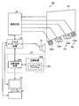
- FIG. 2 is a diagram illustrating an example of a hardware configuration of the visual function detection device 100 according to the present embodiment.
- the visual function detection device 100 includes a display device 101, a stereo camera device 102, a lighting device 103, a computer system 20, an input / output interface device 30, a drive circuit 40, and an output device 50. And an input device 60.
- the computer system 20, the drive circuit 40, the output device 50, and the input device 60 perform data communication via the input / output interface device 30.
- the computer system 20 includes an arithmetic processing device 20A and a storage device 20B.
- the arithmetic processing unit 20A includes a microprocessor such as a CPU (central processing unit).
- the storage device 20B includes a memory or storage such as a ROM (read only memory) and a RAM (random access memory).
- the arithmetic processing device 20A performs arithmetic processing according to the computer program 20C stored in the storage device 20B.
- the arithmetic processing unit 20A executes the computer program 20C stored in the storage device 20B to execute the line-of-sight detection process, and thus can be said to be the line-of-sight detection device according to the present embodiment.
- the drive circuit 40 generates a drive signal and outputs it to the display device 101, the stereo camera device 102, and the illumination device 103. Further, the drive circuit 40 supplies the image data of the eyeball 111 acquired by the stereo camera device 102 to the computer system 20 via the input / output interface device 30.
- the output device 50 includes a display device such as a flat panel display.
- the output device 50 may include a printing device.
- the input device 60 generates input data when operated.
- the input device 60 includes a keyboard or mouse for a computer system.
- the input device 60 may include a touch sensor provided on the display screen of the output device 50 that is a display device.
- the display device 101 and the computer system 20 are separate devices. Note that the display device 101 and the computer system 20 may be integrated.
- the visual function detection device 100 includes a tablet personal computer
- the computer system 20, the input / output interface device 30, the drive circuit 40, and the display device 101 may be mounted on the tablet personal computer.
- FIG. 3 is a functional block diagram showing an example of the visual function detection device 100 according to the present embodiment.
- the input / output interface device 30 includes an input / output unit 302.
- the drive circuit 40 generates a drive signal for driving the display device 101 and outputs the drive signal to the display device 101, and generates a drive signal for driving the first camera 102A to generate the first camera.
- a first camera input / output unit 404A that outputs to the second camera 102B
- a second camera input / output unit 404B that generates a drive signal for driving the second camera 102B and outputs it to the second camera 102B, the first light source 103A and the second light source 103A.
- a light source drive unit 406 that generates a drive signal for driving the two light sources 103B and outputs the drive signals to the first light source 103A and the second light source 103B.
- the first camera input / output unit 404A supplies the image data of the eyeball 111 acquired by the first camera 102A to the computer system 20 via the input / output unit 302.
- the second camera input / output unit 404B supplies the image data of the eyeball 111 acquired by the second camera 102B to the computer system 20 via the input / output unit 302.
- the computer system 20 controls the visual function detection device 100.
- the computer system 20 includes a light source control unit 204, an image data acquisition unit 206, an input data acquisition unit 208, a position detection unit 210, a curvature center calculation unit 212, a gaze point detection unit 214, and a display control unit 216. , A relationship detection unit 218, a visual function detection unit 220, and a storage unit 222.
- the functions of the computer system 20 are exhibited by the arithmetic processing device 20A and the storage device 20B.
- the light source control unit 204 controls the operation state of the first light source 103A and the second light source 103B by controlling the light source driving unit 406.
- the light source control unit 204 controls the first light source 103A and the second light source 103B so that the first light source 103A and the second light source 103B emit detection light at different timings.
- the image data acquisition unit 206 acquires the image data of the eyeball 111 of the subject acquired by the stereo camera device 102 including the first camera 102A and the second camera 102B from the stereo camera device 102 via the input / output unit 302.
- the input data acquisition unit 208 acquires input data generated by operating the input device 60 from the input device 60 via the input / output unit 302.
- the position detection unit 210 detects the position data of the pupil center based on the image data of the eyeball 111 acquired by the image data acquisition unit 206. Further, the position detection unit 210 detects position data of the corneal reflection center based on the image data of the eyeball 111 acquired by the image data acquisition unit 206.
- the pupil center is the center of the pupil 112.
- the cornea reflection center is the center of the cornea reflection image 113.
- the position detection unit 210 detects the position data of the pupil center and the position data of the corneal reflection center for the left and right eyeballs 111 of the subject.
- the curvature center calculation unit 212 calculates position data of the corneal curvature center of the eyeball 111 based on the image data of the eyeball 111 acquired by the image data acquisition unit 206.
- the gaze point detection unit 214 detects the position data of the gaze point of the subject based on the image data of the eyeball 111 acquired by the image data acquisition unit 206.
- the position data of the gazing point refers to position data of the intersection point between the subject's line-of-sight vector defined by the three-dimensional global coordinate system and the display screen 101S of the display device 101.
- the gazing point detection unit 214 detects the eye gaze vectors of the left and right eyeballs 111 of the subject based on the pupil center position data and the corneal curvature center position data acquired from the image data of the eyeball 111. After the gaze vector is detected, the gaze point detection unit 214 detects position data of the gaze point indicating the intersection of the gaze vector and the display screen 101S.
- the display control unit 216 outputs data to at least one of the display device 101 and the output device 50.
- the display control unit 216 outputs data for displaying the determination image 231 on the display device 101 to the display device 101, and displays the determination image 231 on the display screen 101 ⁇ / b> S of the display device 101.
- the determination image 231 displayed by the display control unit 216 will be described later.
- the display control unit 216 may cause the display screen 101 ⁇ / b> S or the output device 50 to display the positions of the gazing points of the left and right eyeballs 111 of the subject H.
- the relationship detection unit 218 detects relationship information that is information indicating a relationship between the moving direction of the determination image 231 on the display screen 101S and the moving direction of the gazing point detected by the gazing point detection unit 214. A method for detecting the relationship information will be described later.
- the visual function detection unit 220 detects the visual function of the subject H based on the relationship information detected by the relationship detection unit 218.
- the visual function detection unit 220 detects the visual function by deriving information serving as a reference for determining whether the determination image 231 is visible to the subject H based on the relationship information.
- detecting the visual function here means deriving information serving as a criterion for determining whether the determination image 231 is visible.
- the visual function detection unit 220 may derive information serving as a reference for determining the visual acuity of the subject based on the determination of whether the determination image 231 is visible to the subject H, for example, whether the image is a cataract. You may derive
- the storage unit 222 stores the image data of the eyeball 111 of the subject H acquired by the image data acquisition unit 206, the position data of the gazing point detected by the gazing point detection unit 214, and the image to be displayed on the display screen 101S (for example, the determination image 231).
- Image data, relationship information detected by the relationship detection unit 218, data of a visual function detection result by the visual function detection unit 220, and the like are stored.
- the storage unit 222 includes a process for displaying an image on the display screen 101S, a process for detecting the position of the gazing point of the subject H who observes the display screen 101S, and the moving direction of the determination image 231 and the moving direction of the gazing point.
- a program for causing a computer to execute processing for detecting related information and processing for detecting a visual function based on the information is stored.
- the curvature center calculation unit 212 calculates position data of the corneal curvature center of the eyeball 111 based on the image data of the eyeball 111.
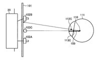
- 4 and 5 are schematic diagrams for explaining a method of calculating position data of the corneal curvature center 110 according to the present embodiment.
- FIG. 4 shows an example in which the eyeball 111 is illuminated by one light source 103C.
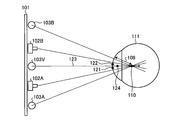
- FIG. 5 shows an example in which the eyeball 111 is illuminated by the first light source 103A and the second light source 103B.
- the light source 103C is disposed between the first camera 102A and the second camera 102B.
- Pupil center 112 ⁇ / b> C is the center of pupil 112.
- the cornea reflection center 113 ⁇ / b> C is the center of the cornea reflection image 113.
- the pupil center 112C indicates the pupil center when the eyeball 111 is illuminated by one light source 103C.
- the corneal reflection center 113C indicates the corneal reflection center when the eyeball 111 is illuminated by one light source 103C.
- the corneal reflection center 113 ⁇ / b> C exists on a straight line connecting the light source 103 ⁇ / b> C and the corneal curvature center 110.
- the corneal reflection center 113C is positioned at the midpoint between the corneal surface and the corneal curvature center 110.
- the corneal curvature radius 109 is the distance between the corneal surface and the corneal curvature center 110.
- the position data of the corneal reflection center 113C is detected by the stereo camera device 102.
- the corneal curvature center 110 exists on a straight line connecting the light source 103C and the corneal reflection center 113C.
- the curvature center calculation unit 212 calculates, as position data of the corneal curvature center 110, position data that has a predetermined distance from the corneal reflection center 113C on the straight line.
- the predetermined value is a value determined in advance from, for example, a general radius of curvature of the cornea, and is stored in the storage unit 222.
- the first camera 102A and the second light source 103B, and the second camera 102B and the first light source 103A are symmetrical with respect to a straight line passing through an intermediate position between the first camera 102A and the second camera 102B. It is arranged at the position. It can be considered that the virtual light source 103V exists at an intermediate position between the first camera 102A and the second camera 102B.
- a corneal reflection center 121 indicates a corneal reflection center in an image obtained by photographing the eyeball 111 with the second camera 102B.
- a corneal reflection center 122 indicates a corneal reflection center in an image obtained by photographing the eyeball 111 with the first camera 102A.
- a corneal reflection center 124 indicates a corneal reflection center corresponding to the virtual light source 103V.
- the position data of the cornea reflection center 124 is calculated based on the position data of the cornea reflection center 121 and the position data of the cornea reflection center 122 acquired by the stereo camera device 102.
- the stereo camera device 102 detects position data of the corneal reflection center 121 and position data of the corneal reflection center 122 in the three-dimensional local coordinate system defined by the stereo camera device 102.
- camera calibration is performed in advance by a stereo calibration method, and conversion parameters for converting the three-dimensional local coordinate system of the stereo camera device 102 into a three-dimensional global coordinate system are calculated.
- the conversion parameter is stored in the storage unit 222.
- the curvature center calculation unit 212 converts the position data of the corneal reflection center 121 and the position data of the corneal reflection center 122 acquired by the stereo camera device 102 into position data in a three-dimensional global coordinate system using the conversion parameters.
- the curvature center calculation unit 212 calculates position data of the corneal reflection center 124 in the three-dimensional global coordinate system based on the position data of the corneal reflection center 121 and the position data of the corneal reflection center 122 defined in the three-dimensional global coordinate system. To do.
- the corneal curvature center 110 exists on a straight line 123 connecting the virtual light source 103 ⁇ / b> V and the corneal reflection center 124.
- the curvature center calculation unit 212 calculates position data on the straight line 123 where the distance from the corneal reflection center 124 is a predetermined value as position data of the corneal curvature center 110.
- the predetermined value is a value determined in advance from, for example, a general radius of curvature of the cornea, and is stored in the storage unit 222.
- the corneal curvature center 110 is calculated by the same method as that used when there is one light source.
- the corneal curvature radius 109 is the distance between the corneal surface and the corneal curvature center 110. Accordingly, the corneal curvature radius 109 is calculated by calculating the position data of the corneal surface and the position data of the corneal curvature center 110.
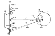
- FIG. 6 is a schematic diagram for explaining an example of calibration processing according to the present embodiment.
- the target position 130 is set in order to make the subject gaze.
- the target position 130 is defined in a three-dimensional global coordinate system.
- the target position 130 is set to the center position of the display screen 101S of the display device 101, for example.
- the target position 130 may be set to the end position of the display screen 101S.
- the output control unit 226 displays the target image at the set target position 130.
- a straight line 131 is a straight line connecting the virtual light source 103V and the corneal reflection center 113C.
- a straight line 132 is a straight line connecting the target position 130 and the pupil center 112C.
- the corneal curvature center 110 is an intersection of the straight line 131 and the straight line 132.
- the curvature center calculation unit 212 is based on the position data of the virtual light source 103V, the position data of the target position 130, the position data of the pupil center 112C, and the position data of the corneal reflection center 113C, and the position data of the corneal curvature center 110. Can be calculated.
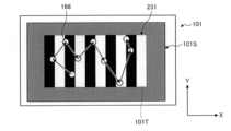
- FIG. 7 is a schematic diagram for explaining an example of a gazing point detection process according to the present embodiment.
- a gazing point 165 indicates a gazing point obtained from the corneal curvature center calculated using a general curvature radius value.
- the gazing point 166 indicates a gazing point obtained from the corneal curvature center calculated using the distance 126 obtained in the calibration process.
- the pupil center 112C indicates the pupil center calculated in the calibration process
- the corneal reflection center 113C indicates the corneal reflection center calculated in the calibration process.
- a straight line 173 is a straight line connecting the virtual light source 103V and the corneal reflection center 113C.
- the corneal curvature center 110 is the position of the corneal curvature center calculated from a general curvature radius value.
- the distance 126 is a distance between the pupil center 112C and the corneal curvature center 110 calculated by the calibration process.
- the corneal curvature center 110H indicates the position of the corrected corneal curvature center obtained by correcting the corneal curvature center 110 using the distance 126.
- the corneal curvature center 110H is obtained from the fact that the corneal curvature center 110 exists on the straight line 173 and the distance between the pupil center 112C and the corneal curvature center 110 is the distance 126.
- the line of sight 177 calculated when a general radius of curvature value is used is corrected to the line of sight 178.
- the gazing point on the display screen 101S of the display device 101 is corrected from the gazing point 165 to the gazing point 166.
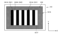
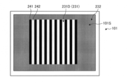
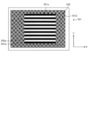
- FIG. 8 is a diagram showing a determination image according to the present embodiment.
- the display control unit 216 When performing the visual function detection, the display control unit 216 outputs data for displaying the image 230 on the display device 101 to the display device 101 to display the image 230 on the display screen 101S of the display device 101.
- the image 230 includes a determination image 231 and a background image 232. That is, the display control unit 216 outputs data for displaying the determination image 231 on the display device 101 and data for displaying the background image 232 on the display screen 101S of the display device 101. It can be said that the determination image 231 and the background image 232 are displayed.
- the image 230 is an image that occupies the entire area of the display screen 101S, but may be an image that occupies a part of the display screen 101S.
- the determination image 231 is displayed in the display area 101T in the area where the image 230 is displayed (here, the display screen 101S). That is, the determination image 231 is displayed so as to occupy the entire display area 101T of the display screen 101S.
- the display area 101T is a partial area of the display screen 101S.
- the display area 101T may occupy the entire display screen 101S.
- the image 230 does not have the background image 232 but only the determination image 231.
- the determination image 231 has a size that is less than or equal to one time the display screen 101S. In this way, the subject H can appropriately visually recognize the determination image 231.
- the judgment image 231 is an image that displays a pattern.
- the determination image 231 includes a first image 241 and a second image 242.
- the display area 101T is divided into a first area where the first image 241 is displayed and a first area where the second image 242 is displayed.
- the first image 241 can be rephrased as the first region where the first image 241 is displayed
- the second image 242 can be rephrased as the second region where the second image 242 is displayed. it can.
- the first image 241 and the second image 242 are images having different brightness from each other.
- the first image 241 is an image having lower luminance than the second image 242.
- the first image 241 and the second image 242 are achromatic images. Accordingly, the first image 241 has a stronger black component than the second image 242, and the second image 242 has a stronger white component than the first image 241.
- the first image 241 and the second image 242 may be colored images as long as they have different luminance.
- the determination image 231 includes a plurality of first images 241 and second images 242, and the first images 241 and the second images 242 are alternately arranged in a stripe shape. Arranged. That is, the first image 241 and the second image 242 have the same length along the Y-axis direction as the length along the Y-axis direction of the display area 101T, and the display area 101T along the Y-axis direction. Extends from the top to the bottom. The first image 241 and the second image 242 have a length (width) along the X-axis direction that is shorter than a length along the X-axis direction of the display region 101T.
- the first image 241 and the second image 242 are alternately arranged along the X-axis direction in the display area 101T.
- the first images 241 that are separated from the end surface along the X-axis direction of the display region 101T have the same area.
- the areas of the second images 242 that are separated from the end surface along the X-axis direction of the display region 101T are also equal.
- the first image 241 and the second image 242 separated from the end surface along the X-axis direction of the display area 101T have the same area.
- the number of first images 241 and the number of second images 242 are also the same. However, the areas and shapes of the first images 241 may be different from each other, and the areas and shapes of the second images 242 may be different from each other.
- the number of first images 241 and the number of second images 242 may be different.
- the background image 232 is an image displayed in an area other than the display area 101T where the determination image 231 is displayed in the area where the image 230 is displayed (here, the display screen 101S). is there. That is, the background image 232 is an image displayed so as to surround the display area 101T (determination image 231). The background image 232 is displayed so as to occupy the entire area other than the display area 101T in the area where the image 230 is displayed. However, the background image 232 may occupy a part of the area other than the display area 101T as long as it surrounds the display area 101T.
- the judgment image 231 is a uniform image without a pattern.
- the background image 232 is an image having a constant luminance throughout the entire area, and more specifically, is the same color as the determination image 231, that is, an achromatic image. Therefore, the background image 232 has a higher luminance and a higher white component than the first image 241. The background image 232 has a lower luminance and a higher black component than the second image 242.
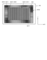
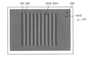
- FIG. 9 is a diagram showing how the judgment image moves.
- the display control unit 216 moves the determination image 231 in the X-axis direction within the display area 101T.
- the display control unit 216 moves the determination image 231 in the X-axis direction within the display area 101T while fixing the position of the display area 101T. That is, it can be said that the determination image 231 is a moving image displayed in the display area 101T.
- the direction in which the determination image 231 is moved is not limited to the X-axis direction, and is arbitrary and may be a predetermined direction that is a predetermined direction.
- the predetermined direction is preferably a direction in which the first image 241 and the second image 242 are arranged as in the present embodiment, but is not limited thereto.
- the display control unit 231 may move the determination image 231 in any direction without being limited to a predetermined direction. That is, the display control unit 231 only needs to move the determination image 231 in the display area 101T. In addition, it is preferable that the display control unit 216 does not switch the direction in which the determination image 231 is moved halfway. Further, the display control unit 216 may move the position of the display area 101T.
- the display control unit 216 scrolls the determination image 231, that is, the first image 241 and the second image 242 along the X-axis direction.
- the display control unit 216 prepares a plurality of determination images 231 in advance.
- These determination images 231 are images in which the display positions of the first image 241 and the second image 242 are shifted from each other along the X-axis direction (for example, images in the states S1 to S4 in FIG. 9). Then, the display control unit 216 displays these determination images 231 in order for each frame.
- the determination image 231 is visually recognized as a moving image scrolled along the X-axis direction between the first image 241 and the second image 242.
- the first image 241 and the second image 242 move in the X-axis direction in the display area 101T as time passes, and the area gradually increases when reaching the end of the display area 101T on the X-axis direction side. It becomes smaller and disappears from the display area 101T. Then, the first image 241 and the second image 242 appear sequentially from the end opposite to the X-axis direction, and move in the X-axis direction when reaching a predetermined area.
- the second image 242S moves in the X-axis direction in the display area 101T as time passes, and reaches the end of the second image 242S in the X-axis direction (the right end in the example of FIG. 9) (FIG. 9). State S1). Thereafter, the area of the second image 242S gradually decreases at the end portion in the X-axis direction (state S2 in FIG. 9), and disappears from the display area 101T after a further time (state S3 in FIG. 9).
- the display control unit 216 moves the determination image 231 for each frame at a predetermined speed.
- the moving speed is about 100 pixels / second or more and 400 pixels / second or less, but is not limited thereto and can be arbitrarily set.
- FIG. 10 to FIG. 12 are diagrams illustrating judgment images having different patterns.
- the display control unit 216 may display different patterns of determination images 231 for visual function detection inspection.
- the display control unit 216 selects any pattern determination image 231 and moves the selected pattern determination image 231 as described above.
- the judgment image 231A shown in FIG. 10, the judgment image 231B shown in FIG. 11, and the judgment image 231C shown in FIG. 12 are different from each other in the size (area) of the first image 241 and the second image 242.
- the numbers of the first image 241 and the second image 242 are also different from each other. That is, the determination images 231A, 231B, and 231C have different density distributions of the first image 241 and the second image 242.
- the determination image 231A, the determination image 231B, and the determination image 231C have the same overall size, that is, the size of the display area 101T, but may be different from each other.
- the first image 241B and the second image 242B of the determination image 231B are smaller in area than the first image 241A and the second image 242A of the determination image 231A. Furthermore, the length along the direction X between the first image 241B and the second image 242B is shorter than the length along the direction X between the first image 241A and the second image 242A.
- the determination image 231B has more first images 241B and second images 242B than the first image 241A and second image 242A of the determination image 231A.
- the areas of the first image 241C and the second image 242C of the determination image 231C are smaller than those of the first image 241B and the second image 242B of the determination image 231B.
- the determination image 231C has more first images 241C and second images 242C than the first image 241B and second image 242B of the determination image 231B.
- the determination image 231B shown in FIG. 11 is less visible to the subject than the determination image 231A because the first image 241 and the second image 242 are smaller than the determination image 231A shown in FIG.
- the determination image 231C illustrated in FIG. 11 is less visible to the subject than the determination image 231B. Therefore, the display control unit 216 can detect the degree of visual function (for example, visual acuity) of the subject H in a stepwise manner by displaying the determination images 231 having different patterns in this way.
- the degree of visual function for example, visual acuity
- the display control unit 216 When performing the visual function detection, the display control unit 216 displays the determination image 231 and the background image 232 on the display screen 101S of the display device 101 in this way.
- the subject H observes the display screen 101S when detecting the visual function, and the gaze point detection unit 214 detects the gaze point 166 of the subject H at that time.
- the relationship detection unit 218 detects relationship information indicating the relationship between the movement direction of the determination image 231 on the display screen 101S and the movement direction of the gazing point detected by the gazing point detection unit 214, and the visual function detection unit 220
- the visual function of the subject H is detected based on the related information.
- the flow for detecting the visual function will be described.
- FIG. 13 is a flowchart for explaining a flow for detecting a visual function.
- FIG. 14 is a diagram for explaining an example of the position of the gazing point.
- the gazing point detection unit 214 performs the gazing point detection process described above (step S10), and the gazing point 166 of the subject H positioned in front of the display screen 101S. The position of is detected.
- the image data of the eyeball 111 of the subject is acquired every predetermined time by the image data acquisition unit 206 imaging. Therefore, the gazing point detection unit 214 detects the position of the gazing point 166 every predetermined time. Since the predetermined time is, for example, about 1/60 seconds, the gazing point 166 is detected about 60 times per second. However, the length of the predetermined time is arbitrary.
- the gaze point detection unit 214 continues to detect the position of the gaze point 166 during a period in which a determination image 231 described later is displayed.
- the visual function detection apparatus 100 causes the display control unit 216 to display the determination image 231 in the display area 101T and scroll (move) the determination image 231 in the display area 101T (step S12). That is, the display control unit 216 continues to display the determination image 231 while scrolling within the display area 101T. And the visual function detection apparatus 100 resets detection time and a calculation result (step S14), and acquires the position detection result of the gaze point 166 (step S16).
- the detection time is a predetermined time, and is a period in which the determination image 231 is displayed and gazing point detection is performed.
- the detection time is, for example, about 20 seconds, but the time is arbitrary.
- the visual function detection device 100 resets the detection time, starts displaying the determination image 231 and starts gazing point detection, and starts counting time from the start timing.
- the calculation result is a calculation result such as a total movement distance described later. That is, resetting the calculation result means that the accumulated total movement distance value is set to zero, and the visual function detection device 100 starts calculating the total movement distance from this timing.
- the visual function detection device 100 detects the position of the gazing point 166 while the determination image 231 is displayed in the display area 101T by the gazing point detection unit 214, and each time the gazing point 166 is detected, The position detection result of the gazing point 166 is acquired.
- FIG. 14 is a diagram for explaining the movement of the gazing point.
- calculation of the movement distance of the gazing point 166B will be described as an example.
- a gazing point 166A in FIG. 14 is a gazing point detected immediately before the gazing point 166B.
- the relationship detection unit 218 calculates the distance between the gazing point 166B and the gazing point 166A as the movement distance.
- the relationship detection unit 218 determines the distance X between the gazing point 166B and the gazing point 166A along the X-axis direction, and the gazing point 166B and the gazing point 166A along the Y-axis direction.
- the distance Y which is the distance of is calculated.
- the relationship detection unit 218 calculates the distance X and the distance Y using the length between the detected gazing point 166 and the gazing point 166 detected immediately before as the movement distance.
- the distance X is a vector component along the moving direction of the determination image 231 between the gazing point 166B and the gazing point 166A
- the distance Y is between the gazing point 166B and the gazing point 166A.
- the distance is a vector component in a direction orthogonal to the moving direction of the determination image 231.
- the distance X calculated here is not necessarily limited to the X-axis direction, and may be an arbitrary direction. That is, the distance X is a vector component along an arbitrary direction (first direction) of the distance between the gazing point 166B and the gazing point 166A (the moving distance of the gazing point for each detection), and the distance Y is The vector component along the direction orthogonal to the arbitrary direction (first direction) of the distance between the gazing point 166B and the gazing point 166A may be used.
- the visual function detection device 100 calculates the total movement distance of the gazing point 166 by the relationship detection unit 218 (step S20).
- the relationship detection unit 218 adds up all the movement distances calculated so far to calculate the total movement distance. Therefore, the relationship detection unit 218 calculates the total movement distance by adding the movement distance detected at the current timing to the total movement distance calculated at the immediately preceding timing.
- the component relationship detection unit 218 detects this total movement distance as relationship information. Specifically, the relationship detection unit 218 calculates the total movement distance in the X-axis direction and the total movement distance in the Y-axis direction using the following formulas (1) and (2).
- XSUM is the total movement distance in the X-axis direction
- XSUM ( ⁇ 1) is the total movement distance calculated at the previous timing
- Y SUM is the total movement distance in the Y-axis direction
- Y SUM ( ⁇ 1) is the total movement distance calculated at the previous timing.
- the visual function detection device 100 determines whether the detection time has elapsed (step S22). If the detection time has not elapsed (step S22; No), the process returns to step S16, and thereafter Repeat the process. That is, the visual function detection device 100 acquires the position information of the gazing point 166 detected at the next timing, and updates the total movement distance. The visual function detection device 100 repeats the update of the total movement distance until the detection time elapses.
- the visual function detection device 100 calculates the differential movement distance by the visual function detection unit 220 (step S24), and determines whether the differential movement distance is greater than the threshold value (step S24). Step S26).
- the visual function detection unit 220 calculates a difference between the total movement distance XSUM in the X-axis direction and the total movement distance YSUM in the Y-axis direction as a difference movement distance, and based on the difference movement distance, an inspection standard is calculated. Judge whether to meet. More specifically, the visual function detection unit 220 calculates a value obtained by subtracting the total movement distance YSUM from the total movement distance XSUM as the difference movement distance.
- the visual function detection unit 220 determines whether or not the differential movement distance is greater than a predetermined threshold value. If the difference movement distance is greater than the threshold value (step S26; Yes), the visual function of the subject H satisfies the inspection standard. (Step S28). On the other hand, the visual function detection unit 220 determines that the visual function of the subject H does not satisfy the inspection standard when the differential moving distance is not greater than the threshold (step S26; No), that is, when the difference is equal to or less than the threshold (step) S29). This process ends by this step S28 or S29. The visual function detection unit 220 derives a determination result as to whether or not the inspection standard is satisfied as information serving as a reference for detecting the visual function, and stores the information in the storage unit 222, for example.
- FIG. 15 is a diagram for explaining an example of the position of the gazing point.
- FIG. 14 is an example when the subject H can visually recognize the determination image 231
- FIG. 15 is an example when the subject H cannot visually recognize the determination image 231.
- the determination image 231 is a moving image that moves in a predetermined direction (here, the X-axis direction) within the display area 101T. Therefore, the image for determination 231 exhibits a function like an OKN (Optokinetic Nystagmus) and when the subject H can visually recognize the subject H,
- the eyeball 111 is reciprocated along the moving direction of the determination image 231 (here, the X-axis direction).
- the gazing point 166 has a trajectory that reciprocates along the X-axis direction in accordance with the movement of the determination image 231 as illustrated in FIG. 14. Become.
- the gazing point 166 does not correspond to the movement of the determination image 231 as illustrated in FIG. 15, and the trajectory reciprocates along the X-axis direction. There is a tendency not to become.
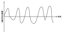
- FIG. 16 and 17 are graphs showing an example of changes in the coordinates of the gazing point over time.
- FIG. 16 illustrates an example of changes in coordinates in the X-axis direction of the gazing point 166 when the subject H can visually recognize the determination image 231
- FIG. 17 illustrates that the subject H visually recognizes the determination image 231.
- the example of the change of the coordinate of the Y-axis direction of the gaze point 166 in the case of being made is shown.
- the gaze point 166 tends to change coordinates as shown in FIGS.
- the visual function detection unit 220 calculates the difference movement distance by subtracting the total movement distance YSUM from the total movement distance XSUM , and makes a determination based on the difference movement distance, so It is appropriately detected whether the viewpoint 166 has a tendency as shown in FIGS. Therefore, according to the visual function detection device 100, the visual function of the subject can be appropriately inspected.
- the relationship detection unit 218 may collectively calculate the total movement distance after the detection period has elapsed.
- the determination by the visual function detection unit 220 is not limited to the determination based on the difference movement distance.
- the following method can also be used for determination. That is, when the relationship detection unit 218 acquires the position detection result of the gazing point 166 in step S16, the relationship detection unit 218 substitutes the position detection result into the array each time. That is, the relationship detection unit 218 stores the position information of the gazing point 166 of the gazing point 166 for each timing. Then, when the detection time has elapsed, the relationship detection unit 218 calculates a moving average value in the X-axis direction and a moving average value in the Y-axis direction of the gazing point 166.
- the moving average value is a value obtained by averaging certain data with the latest data.
- the coordinate value of the gazing point 166 at a certain timing is summed with the coordinate value of the gazing point 166 at the latest timing (for example, the immediately preceding timing and the immediately following timing), and divided by the total number of gazing points 166.
- the moving average is calculated. That is, the relationship detection unit 218 adds up the X-axis direction coordinates of the gazing point 166 and the X-axis direction coordinates of the gazing point 166 detected at the most recent timing of the gazing point 166, and adds up the total gazing point 166.
- the moving average value in the X-axis direction is calculated by dividing by the number of.
- the relationship detection unit 218 adds the coordinates of the gazing point 166 in the Y-axis direction and the coordinates of the gazing point 166 detected at the most recent timing of the gazing point 166 in the Y-axis direction.
- the moving average value in the Y-axis direction is calculated by dividing by the number of.
- the relationship detection unit 218 calculates the moving average value in the X-axis direction and the moving average value in the Y-axis direction for all the gazing points 166.
- the relationship detecting unit 218 arranges the moving average value in the X-axis direction and the moving average value in the Y-axis direction for each gazing point 166 in time series, and extracts the number of times the moving direction is reversed.
- the coordinate has moved to the plus side with the passage of time, while the coordinate has moved to the minus side at the next timing, and the coordinate has moved to the minus side with the passage of time. On the other hand, it may move to the plus side at the next timing.
- the relationship detection unit 218 detects the number of times the movement direction is reversed in the X-axis direction and the number of times the movement direction is reversed along the Y-axis direction as relationship information.
- the visual function detection unit 220 calculates the difference between the number of times the movement direction in the X-axis direction is reversed and the number of times the movement direction in the Y-axis direction is reversed as a difference number, and based on the difference number, the inspection standard is calculated. Judge whether to meet. More specifically, the visual function detection unit 220 calculates, as the number of differences, a value obtained by subtracting the number of times the moving direction in the Y-axis direction is reversed from the number of times the moving direction in the X-axis direction is reversed. The visual function detection unit 220 determines whether or not the difference moving distance is greater than a predetermined threshold. If the difference moving distance is greater than the threshold, the visual function detection unit 220 determines that the inspection standard is satisfied. Judge.
- the determination by the visual function detection unit 220 is not limited to that based on the difference moving distance or the moving average value. Based on the vector component along the moving direction of the determination image 231 and the vector component along the direction orthogonal to the moving direction in the moving direction of the gazing point 166, the visual function detecting unit 220 What is necessary is just to detect a function.
- the visual function detection unit 220 determines that the subject H determines the determination image 231 when the vector component along the movement direction of the determination image 231 is higher than the vector component along the direction orthogonal to the movement direction.
- the determination result that the possibility of being visible is high is derived.
- the determination result may be derived by another method.
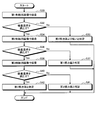
- FIG. 18 is a flowchart showing a method for detecting the visual function in stages.
- FIG. 18 is a flowchart illustrating an example of detecting the visual acuity of a subject.
- the visual function detection device 100 first performs an inspection using the first determination image (step S30).
- the first determination image is an image in which the areas of the first image 241 and the second image 242 are large among the determination images 231 of a plurality of patterns. In the example of this embodiment, the determination image shown in FIG. 231A.
- step S30 the visual function detection device 100 uses the first determination image (determination image 231A) to perform the inspection shown in FIG. That is, in this case, the visual function detection device 100 determines whether the inspection standard is satisfied by displaying the first determination image (determination image 231A).
- the visual function detection device 100 determines that the visual acuity of the subject H is lower than the first visual acuity value (Ste S33), the process is terminated.
- the first visual acuity value is visual acuity when it is determined that the inspection standard of the first determination image is satisfied, and is, for example, 0.3.
- the value of the first visual acuity value is determined by the shape of the first determination image, that is, the size of the first image 241 and the second image 242.
- the visual function detection device 100 performs the inspection with the second determination image (step S34).
- the second determination image is an image in which the areas of the first image 241 and the second image 242 are smaller than those of the first determination image.
- the second determination image is the determination image 231B illustrated in FIG.
- the visual function detection device 100 uses the second determination image (determination image 231 ⁇ / b> B) to perform the inspection illustrated in FIG. 13 and determine whether the inspection standard is satisfied.
- the visual function detection device 100 determines that the visual acuity of the subject H is the first visual acuity value (Ste S37), the process is terminated.
- the visual function detection device 100 performs the inspection with the third determination image (step S38).
- the third determination image is an image in which the areas of the first image 241 and the second image 242 are smaller than those of the second determination image.
- the third determination image is the determination image 231C illustrated in FIG.
- the visual function detection device 100 uses the third determination image (determination image 231 ⁇ / b> C) to perform the inspection illustrated in FIG. 13 and determine whether the inspection standard is satisfied.
- the visual function detection device 100 determines that the visual acuity of the subject H is the second visual acuity value (Ste S41), the process ends.
- the second visual acuity value is visual acuity when it is determined that the inspection standard of the second determination image is satisfied, and is higher than the first visual acuity value.
- the second visual acuity value is, for example, 0.5.
- the value of the second visual acuity value is determined by the shape of the second determination image, that is, the size of the first image 241 and the second image 242.
- the visual function detection device 100 determines that the visual acuity of the subject H is the third visual acuity value (step) S42), this process is terminated.
- the third visual acuity value is visual acuity when it is determined that the inspection standard of the third determination image is satisfied, and is higher than the second visual acuity value.
- the third visual acuity value is, for example, 1.0.
- the value of the third visual acuity value is determined by the shape of the third determination image, that is, the size of the first image 241 and the second image 242.
- the visual function detection unit 220 uses information determined as the visual acuity values (first visual acuity value, second visual acuity value, and third visual acuity value) determined in this way as information for detecting visual acuity as a visual function. And is stored in the storage unit 222, for example.
- the visual function detection device 100 stops the display of the determination image 231 and starts the inspection with the next determination image 231 when the inspection with one determination image 231 ends. doing.
- the visual function detection apparatus 100 may continuously perform the inspection with the plurality of determination images 231.
- the visual function detection device 100 returns to step S12 to display another determination image 231 from the next frame, and similarly in the display area 101T. You may inspect while scrolling. For example, if the visual function detection device 100 displays the determination image 231A for the detection time, the visual inspection may be continued from the next frame to, for example, the determination image 231B.
- the visual function detection device 100 can display the determination image 231B for the detection time and then switch from the next frame to the determination image 231A, for example, when an image with a certain visual acuity is not visible. It is possible to return to the examination with an image for low vision.
- the determination image 231 serving as a higher inspection standard include an image in which the first image 241 and the second image 242 are smaller than the third determination image.
- the determination image 231 serving as a higher inspection standard may be the determination image 231 having a smaller contrast than the third determination image.
- the contrast is the degree of difference in luminance between the maximum luminance and the minimum luminance in the determination image 231.
- the contrast is the luminance of the pixel having the maximum luminance among the pixels in the determination image 231, that is, the maximum luminance, and the luminance of the pixel having the minimum luminance among the pixels in the determination image 231, that is, the minimum luminance. It is the value divided.
- the determination image 231D shown in FIG. 19 and the determination image 231E shown in FIG. 20 are equal in size to the first image 241 and the second image 242.
- the determination image 231E shown in FIG. 20 has a smaller contrast than the determination image 231D shown in FIG. That is, the determination image 231E has a smaller degree of difference in luminance between the maximum luminance and the minimum luminance than the determination image 231D. Therefore, the determination image 231E is less visible to the subject H than the determination image 231D.
- the second image 242 has the maximum luminance
- the first image 241 has the minimum luminance. If the contrast is reduced, the luminance difference between the first image 241 and the second image 242 is reduced, so that the subject is difficult to visually recognize.
- stepwise inspection can also be performed by changing the contrast of the judgment image 231.
- the visual function detection apparatus 100 may perform inspection using only the determination image 231 having a different size between the first image 241 and the second image 242 or use only the determination image 231 having a different contrast. May be used, or both of them may be used or combined.
- the visual function detection device 100 includes the display control unit 216, the gaze point detection unit 214, the relationship detection unit 218, and the visual function detection unit 220.
- the display control unit 216 displays the determination image 231 in the display area 101T on the display screen 101S of the display unit (display device 101), and moves the determination image 231 within the display area 101T.
- the gaze point detection unit 214 detects the position on the display screen 101S of the gaze point of the subject H who observes the display screen 101S.
- the relationship detection unit 218 detects relationship information between the moving direction of the determination image 231 and the moving direction of the gazing point 166.
- the visual function detection unit 220 detects the visual function of the subject H based on the relationship information.
- the visual function detection device 100 displays the determination image 231 that draws the attention of the subject H, and guides the visual line of the subject H to the determination image 231 when the determination image 231 is visible. Furthermore, the visual function detection device 100 displays the determination image 231 so that the determination image 231 moves in the display area 101T. Therefore, when the determination image 231 is visible, the subject's line of sight moves more in the direction along the moving direction of the determination image 231.
- the visual function detection device 100 detects the gaze of the subject as a gazing point, determines whether the subject H can visually recognize the determination image 231 based on the moving direction of the gazing point, and determines the visual function of the subject H. Detected.
- the visual function detection device 100 self-reporting as to whether or not the visual recognition is possible is not required, the gazing point can be appropriately detected, and whether or not the subject H can visually recognize the determination image 231 based on the gazing point appropriately. I can judge. Therefore, according to the visual function detection device 100, the visual function of the subject H can be appropriately inspected.
- the visual function is detected based on the moving direction of the gazing point 166.
- the visual function detection device 100 may detect the visual function based on the moving direction of the eyeball 111 of the subject H without detecting the gazing point 166. That is, the visual function detection device 100 includes a display control unit 216, a detection unit that detects the movement of the eyeball 111 of the subject H who observes the display screen 101S, and the movement direction of the determination image 231 and the movement direction of the eyeball 111. You may have the relationship detection part 218 which detects relationship information, and the visual function detection part 220 which detects the test subject's H visual function based on relationship information.
- the determination image 231 When the determination image 231 is visible, the subject H moves the eyeball 111 more greatly in the direction along the moving direction of the determination image 231. Therefore, if the eyeball 111 is larger in the movement direction or more moved in the movement direction than the direction orthogonal to the movement direction, the visual function detection unit 220 displays the disconnection image 231 in the same manner as when the gaze point 166 is detected. It is possible to derive information that serves as a criterion for determining that the user can visually recognize.
- the detection unit detects the movement of the eyeball 111 based on the image data of the eyeball 111 acquired by the image data acquisition unit 206.
- the detection unit may be the position detection unit 210, for example.
- the relationship detection unit 218 can detect the relationship information using the position data of the pupil center detected by the position detection unit 210 in the same manner as the gazing point 166.
- the detection unit is not limited to the position detection unit 210 as long as it can detect the movement of the eyeball 111 based on the image data of the eyeball 111.
- the display control unit 216 displays the determination image 231 over the entire display area 101T, and the determination image 231 includes a first image 241 and a second image 242 having different luminances.
- the visual function detection device 100 displays the determination image 231 over the entire display area 101T, and then displays the first image 241 and the second image 242 having different luminances as the determination image 231.
- H is visible, it is possible to appropriately inspect the visual function by guiding the line of sight appropriately.
- the display control unit 216 scrolls the first image 241 and the second image 242 in a predetermined direction within the display area 101T.
- the visual function detection device 100 scrolls the first image 241 and the second image 242 to appropriately inspect the visual function by appropriately guiding the line of sight when the subject H can visually recognize the visual function. Can do.
- the display control unit 216 displays a plurality of first images 241 and a plurality of second images 242 in the display area 101T.
- the display control unit 216 displays the first image 241 and the second image 241 so that the area gradually increases at the end of the display region 101T opposite to the predetermined direction (X-axis direction in the present embodiment).
- the predetermined direction X-axis direction in the present embodiment.
- the visual function detection device 100 appropriately scrolls the first image 241 and the second image 242 in this way, so that when the subject H can visually recognize, the visual function is appropriately guided and the visual function is appropriately adjusted. Can be inspected.
- the display control unit 216 moves the first image 241 and the second image 242 when the first image 241 and the second image 242 move to the end of the display area 101T in a predetermined direction (X-axis direction in the present embodiment). After gradually reducing the area, the display of the first image 241 and the second image 242 at the end in the predetermined direction is terminated.
- the visual function detection device 100 appropriately scrolls the first image 241 and the second image 242 in this way, so that when the subject H can visually recognize, the visual function is appropriately guided and the visual function is appropriately adjusted. Can be inspected.
- the display control unit 216 displays a plurality of first images 241 and a plurality of second images 242 in the display area 101T, and a plurality of types of sizes of the first image 241 and the second image 242 are different from each other.
- the determination image 231 is displayed at different timings.
- the visual function detection unit 220 detects the visual function of the subject H based on the relationship information for each of the plurality of types of determination images 231.
- the visual function detection device 100 can evaluate the visual function in stages by performing an inspection for each of the plurality of types of determination images 231.
- the display control unit 216 displays a plurality of types of determination images 231 having different contrasts at different timings, and the visual function detection unit 220 displays the visual field of the subject H based on the relationship information for each of the plurality of types of determination images 231. Detect function. Since the visual function detection apparatus 100 performs inspection for each determination image 231 having a different contrast, the visual function can be evaluated in stages.
- the visual function detecting unit 220 Based on the vector component along the arbitrary first direction and the vector component along the direction orthogonal to the first direction in the moving direction of the gazing point 166, the visual function detecting unit 220 Detect visual function.
- the visual function detection unit 220 performs evaluation by decomposing the moving direction of the gazing point 166 into a vector component along the moving direction of the determination image 231 and a vector component along a direction orthogonal to the moving direction. Therefore, the visual function detection apparatus 100 can appropriately evaluate the visual function by appropriately detecting the movement of the gazing point 166 along the moving direction of the determination image 231.
- FIG. 21 to FIG. 23 are diagrams showing other examples of determination images.
- the determination image 231 of the present embodiment has a stripe shape in which the first image 241 and the second image 242 are alternately arranged along the X-axis direction, but the display of the determination image 231 is not limited thereto.
- the first image 241a and the second image 242a may have a stripe shape alternately arranged along the Y-axis direction.
- the moving direction of the determination image 231 is preferably the Y-axis direction.
- the visual function detection device 100 detects both the reaction to the movement in the X-axis direction and the reaction to the movement in the Y-axis direction by performing inspection by switching between the determination image 231 and the determination image 231a. can do.
- the moving direction of the determination image 231 is not limited to the X-axis direction and the Y-axis direction, and may be, for example, a direction that intersects both the X-axis direction and the Y-axis direction, that is, an oblique direction.
- the first image 241b and the second image 242b may be a checkered pattern alternately arranged along the X-axis direction and the Y-axis direction.
- the first image 241c and the second image 242c may be images having different luminance and shape.
- the first image 241c and the second image 242c are fruits, but not limited thereto.
- DESCRIPTION OF SYMBOLS 20 ... Computer system, control part, 20A ... Arithmetic processing device, 20B ... Storage device, 20C ... Computer program, 30 ... Input / output interface device, 40 ... Drive circuit, 50 ... Output device, 60 ... Input device, 100 ... Visual function Detection device, 101 ... display device, 101S ... display screen, 101T ... display area, 102 ... stereo camera device, 102A ... first camera, 102B ... second camera, 103 ... illumination device, 103A ... first light source, 103B ... first Two light sources, 103C ... light source, 103V ... virtual light source, 109 ... corneal curvature radius, 110, 110H ...
- corneal curvature center 111 ... eyeball, eye, 112 ... pupil, 112C ... pupil center, 113 ... corneal reflection image, 113C, 121 122, 124 ... corneal reflection center, 123, 131, 132, 173 ... straight line, 126 ... distance, 30 ... target position, 166 ... gazing point, 177, 178 ... gaze, 204 ... light source control unit, 206 ... image data acquisition unit, 208 ... input data acquisition unit, 210 ... position detection unit, 212 ... curvature center calculation unit, 214 Reference point detection unit, 216 ... Display control unit, 218 ... Relationship detection unit, 220 ... Visual function detection unit, 222 ... Storage unit, 231 ... Judgment image, 232 ... Background image, 241 ... First image, 242 ... Second image.
Landscapes
- Engineering & Computer Science (AREA)
- Health & Medical Sciences (AREA)
- Life Sciences & Earth Sciences (AREA)
- Physics & Mathematics (AREA)
- Theoretical Computer Science (AREA)
- General Engineering & Computer Science (AREA)
- Surgery (AREA)
- Public Health (AREA)
- Medical Informatics (AREA)
- Molecular Biology (AREA)
- Biomedical Technology (AREA)
- Animal Behavior & Ethology (AREA)
- General Health & Medical Sciences (AREA)
- Heart & Thoracic Surgery (AREA)
- Veterinary Medicine (AREA)
- Biophysics (AREA)
- Ophthalmology & Optometry (AREA)
- Human Computer Interaction (AREA)
- General Physics & Mathematics (AREA)
- Eye Examination Apparatus (AREA)
Priority Applications (2)
| Application Number | Priority Date | Filing Date | Title |
|---|---|---|---|
| EP19761585.9A EP3744229B1 (en) | 2018-03-01 | 2019-02-13 | Visual function detection device, visual function detection method, and program |
| US16/997,988 US11883102B2 (en) | 2018-03-01 | 2020-08-20 | Visual function detection apparatus, method of detecting visual function, and program |
Applications Claiming Priority (2)
| Application Number | Priority Date | Filing Date | Title |
|---|---|---|---|
| JP2018-036570 | 2018-03-01 | ||
| JP2018036570A JP6950582B2 (ja) | 2018-03-01 | 2018-03-01 | 視機能検出装置、視機能検出方法及びプログラム |
Related Child Applications (1)
| Application Number | Title | Priority Date | Filing Date |
|---|---|---|---|
| US16/997,988 Continuation US11883102B2 (en) | 2018-03-01 | 2020-08-20 | Visual function detection apparatus, method of detecting visual function, and program |
Publications (1)
| Publication Number | Publication Date |
|---|---|
| WO2019167626A1 true WO2019167626A1 (ja) | 2019-09-06 |
Family
ID=67805251
Family Applications (1)
| Application Number | Title | Priority Date | Filing Date |
|---|---|---|---|
| PCT/JP2019/005155 Ceased WO2019167626A1 (ja) | 2018-03-01 | 2019-02-13 | 視機能検出装置、視機能検出方法及びプログラム |
Country Status (4)
| Country | Link |
|---|---|
| US (1) | US11883102B2 (enExample) |
| EP (1) | EP3744229B1 (enExample) |
| JP (1) | JP6950582B2 (enExample) |
| WO (1) | WO2019167626A1 (enExample) |
Families Citing this family (4)
| Publication number | Priority date | Publication date | Assignee | Title |
|---|---|---|---|---|
| US11789259B2 (en) * | 2020-12-28 | 2023-10-17 | Passion Light Inc. | Vision inspection and correction method, together with the system apparatus thereof |
| US20220338729A1 (en) * | 2021-04-27 | 2022-10-27 | Johnson & Johnson Vision Care, Inc. | System and method for identifying presbyopia |
| JP7693397B2 (ja) * | 2021-05-31 | 2025-06-17 | キヤノン株式会社 | 視線情報取得装置、撮像装置、視線情報取得方法、プログラム、及び、記憶媒体 |
| US20240029227A1 (en) * | 2022-07-19 | 2024-01-25 | Qualcomm Incorporated | Screen defect and contamination detection for mobile devices |
Citations (4)
| Publication number | Priority date | Publication date | Assignee | Title |
|---|---|---|---|---|
| JPH11225964A (ja) * | 1998-02-16 | 1999-08-24 | Canon Inc | 眼科検査装置 |
| JP2007143665A (ja) | 2005-11-24 | 2007-06-14 | Funai Electric Co Ltd | 視力検査機能付きテレビジョン装置および映像表示装置 |
| JP4683280B2 (ja) | 2005-07-29 | 2011-05-18 | 株式会社ニデック | 視力検査装置 |
| JP2018019978A (ja) * | 2016-08-04 | 2018-02-08 | 国立大学法人岩手大学 | 視機能検査システム |
Family Cites Families (7)
| Publication number | Priority date | Publication date | Assignee | Title |
|---|---|---|---|---|
| CN101489467B (zh) * | 2006-07-14 | 2011-05-04 | 松下电器产业株式会社 | 视线方向检测装置和视线方向检测方法 |
| US9179833B2 (en) * | 2013-02-28 | 2015-11-10 | Carl Zeiss Meditec, Inc. | Systems and methods for improved ease and accuracy of gaze tracking |
| WO2016132804A1 (ja) * | 2015-02-17 | 2016-08-25 | ローム株式会社 | 視力検査装置および視力検査システム |
| JP6553418B2 (ja) * | 2015-06-12 | 2019-07-31 | パナソニック インテレクチュアル プロパティ コーポレーション オブ アメリカPanasonic Intellectual Property Corporation of America | 表示制御方法、表示制御装置及び制御プログラム |
| EP3493728B1 (en) * | 2016-08-02 | 2025-11-05 | New York University | Methods and kits for assessing neurological function and localizing neurological lesions |
| JP7070003B2 (ja) * | 2018-04-13 | 2022-05-18 | 京セラドキュメントソリューションズ株式会社 | 表示装置及び画像形成装置 |
| KR102719638B1 (ko) * | 2018-12-18 | 2024-10-21 | 현대자동차주식회사 | 차량의 주행 정보 제공 방법, 장치 및 기록매체 |
-
2018
- 2018-03-01 JP JP2018036570A patent/JP6950582B2/ja active Active
-
2019
- 2019-02-13 EP EP19761585.9A patent/EP3744229B1/en active Active
- 2019-02-13 WO PCT/JP2019/005155 patent/WO2019167626A1/ja not_active Ceased
-
2020
- 2020-08-20 US US16/997,988 patent/US11883102B2/en active Active
Patent Citations (4)
| Publication number | Priority date | Publication date | Assignee | Title |
|---|---|---|---|---|
| JPH11225964A (ja) * | 1998-02-16 | 1999-08-24 | Canon Inc | 眼科検査装置 |
| JP4683280B2 (ja) | 2005-07-29 | 2011-05-18 | 株式会社ニデック | 視力検査装置 |
| JP2007143665A (ja) | 2005-11-24 | 2007-06-14 | Funai Electric Co Ltd | 視力検査機能付きテレビジョン装置および映像表示装置 |
| JP2018019978A (ja) * | 2016-08-04 | 2018-02-08 | 国立大学法人岩手大学 | 視機能検査システム |
Non-Patent Citations (2)
| Title |
|---|
| MASAKO MORITA: "visual acuity measurement by optokinetic nystagmus suppression using varied contrasts macular diseases and functional amblyopia", JOURNAL OF THE EYE, vol. 23, no. 12, 1 January 2006 (2006-01-01), pages 1628 - 1630, XP009522814, ISSN: 0910-1810 * |
| See also references of EP3744229A4 |
Also Published As
| Publication number | Publication date |
|---|---|
| US11883102B2 (en) | 2024-01-30 |
| US20200375454A1 (en) | 2020-12-03 |
| JP2019150250A (ja) | 2019-09-12 |
| EP3744229A4 (en) | 2021-03-17 |
| EP3744229A1 (en) | 2020-12-02 |
| JP6950582B2 (ja) | 2021-10-13 |
| EP3744229B1 (en) | 2022-06-01 |
Similar Documents
| Publication | Publication Date | Title |
|---|---|---|
| US11883102B2 (en) | Visual function detection apparatus, method of detecting visual function, and program | |
| US20210303066A1 (en) | Display device, display method, and computer-readable storage medium | |
| US11957411B2 (en) | Visual function detection apparatus, method of detecting visual function, and program | |
| JP6996343B2 (ja) | 評価装置、評価方法、及び評価プログラム | |
| EP3878373B1 (en) | Evaluation device, evaluation method, and evaluation program | |
| JP6958507B2 (ja) | 視線検出装置、視線検出方法及び視線検出プログラム | |
| JP7556213B2 (ja) | 視線検出装置、視線検出方法、及び視線検出プログラム | |
| JP7043889B2 (ja) | 視機能検出装置、視機能検出方法及びプログラム | |
| JP7043890B2 (ja) | 視機能検出装置、視機能検出方法及びプログラム | |
| US11653831B2 (en) | Visual performance examination device, visual performance examination method, and computer program | |
| WO2019181272A1 (ja) | 評価装置、評価方法、及び評価プログラム | |
| JP7027958B2 (ja) | 評価装置、評価方法、及び評価プログラム | |
| JP7722016B2 (ja) | 視線検出装置、視線検出方法及び視線検出プログラム | |
| US12507888B2 (en) | Eye-gaze detecting device, eye-gaze detecting method, and computer-readable storage medium | |
| JP7725918B2 (ja) | 視線検出装置、視線検出方法及び視線検出プログラム | |
| WO2023008023A1 (ja) | 視線検出装置、視線検出方法及び視線検出プログラム | |
| JP2022036452A (ja) | 視線検出装置、視線検出方法及び視線検出プログラム | |
| WO2021131335A1 (ja) | 角膜反射検出装置、視線検出装置、角膜反射検出方法、及び角膜反射検出プログラム |
Legal Events
| Date | Code | Title | Description |
|---|---|---|---|
| 121 | Ep: the epo has been informed by wipo that ep was designated in this application |
Ref document number: 19761585 Country of ref document: EP Kind code of ref document: A1 |
|
| NENP | Non-entry into the national phase |
Ref country code: DE |
|
| ENP | Entry into the national phase |
Ref document number: 2019761585 Country of ref document: EP Effective date: 20200828 |