WO2019167528A1 - Instrument d'observation médicale - Google Patents
Instrument d'observation médicale Download PDFInfo
- Publication number
- WO2019167528A1 WO2019167528A1 PCT/JP2019/003206 JP2019003206W WO2019167528A1 WO 2019167528 A1 WO2019167528 A1 WO 2019167528A1 JP 2019003206 W JP2019003206 W JP 2019003206W WO 2019167528 A1 WO2019167528 A1 WO 2019167528A1
- Authority
- WO
- WIPO (PCT)
- Prior art keywords
- axis
- arm
- medical observation
- imaging device
- observation apparatus
- Prior art date
Links
Images


Classifications
-
- A—HUMAN NECESSITIES
- A61—MEDICAL OR VETERINARY SCIENCE; HYGIENE
- A61B—DIAGNOSIS; SURGERY; IDENTIFICATION
- A61B90/00—Instruments, implements or accessories specially adapted for surgery or diagnosis and not covered by any of the groups A61B1/00 - A61B50/00, e.g. for luxation treatment or for protecting wound edges
- A61B90/20—Surgical microscopes characterised by non-optical aspects
- A61B90/25—Supports therefor
-
- A—HUMAN NECESSITIES
- A61—MEDICAL OR VETERINARY SCIENCE; HYGIENE
- A61B—DIAGNOSIS; SURGERY; IDENTIFICATION
- A61B34/00—Computer-aided surgery; Manipulators or robots specially adapted for use in surgery
- A61B34/30—Surgical robots
-
- A—HUMAN NECESSITIES
- A61—MEDICAL OR VETERINARY SCIENCE; HYGIENE
- A61B—DIAGNOSIS; SURGERY; IDENTIFICATION
- A61B90/00—Instruments, implements or accessories specially adapted for surgery or diagnosis and not covered by any of the groups A61B1/00 - A61B50/00, e.g. for luxation treatment or for protecting wound edges
- A61B90/36—Image-producing devices or illumination devices not otherwise provided for
- A61B90/361—Image-producing devices, e.g. surgical cameras
-
- G—PHYSICS
- G02—OPTICS
- G02B—OPTICAL ELEMENTS, SYSTEMS OR APPARATUS
- G02B7/00—Mountings, adjusting means, or light-tight connections, for optical elements
- G02B7/001—Counterbalanced structures, e.g. surgical microscopes
-
- G—PHYSICS
- G03—PHOTOGRAPHY; CINEMATOGRAPHY; ANALOGOUS TECHNIQUES USING WAVES OTHER THAN OPTICAL WAVES; ELECTROGRAPHY; HOLOGRAPHY
- G03B—APPARATUS OR ARRANGEMENTS FOR TAKING PHOTOGRAPHS OR FOR PROJECTING OR VIEWING THEM; APPARATUS OR ARRANGEMENTS EMPLOYING ANALOGOUS TECHNIQUES USING WAVES OTHER THAN OPTICAL WAVES; ACCESSORIES THEREFOR
- G03B15/00—Special procedures for taking photographs; Apparatus therefor
- G03B15/14—Special procedures for taking photographs; Apparatus therefor for taking photographs during medical operations
-
- G—PHYSICS
- G03—PHOTOGRAPHY; CINEMATOGRAPHY; ANALOGOUS TECHNIQUES USING WAVES OTHER THAN OPTICAL WAVES; ELECTROGRAPHY; HOLOGRAPHY
- G03B—APPARATUS OR ARRANGEMENTS FOR TAKING PHOTOGRAPHS OR FOR PROJECTING OR VIEWING THEM; APPARATUS OR ARRANGEMENTS EMPLOYING ANALOGOUS TECHNIQUES USING WAVES OTHER THAN OPTICAL WAVES; ACCESSORIES THEREFOR
- G03B17/00—Details of cameras or camera bodies; Accessories therefor
- G03B17/56—Accessories
- G03B17/561—Support related camera accessories
-
- H—ELECTRICITY
- H04—ELECTRIC COMMUNICATION TECHNIQUE
- H04N—PICTORIAL COMMUNICATION, e.g. TELEVISION
- H04N23/00—Cameras or camera modules comprising electronic image sensors; Control thereof
- H04N23/50—Constructional details
- H04N23/54—Mounting of pick-up tubes, electronic image sensors, deviation or focusing coils
-
- H—ELECTRICITY
- H04—ELECTRIC COMMUNICATION TECHNIQUE
- H04N—PICTORIAL COMMUNICATION, e.g. TELEVISION
- H04N23/00—Cameras or camera modules comprising electronic image sensors; Control thereof
- H04N23/60—Control of cameras or camera modules
- H04N23/695—Control of camera direction for changing a field of view, e.g. pan, tilt or based on tracking of objects
-
- H—ELECTRICITY
- H10—SEMICONDUCTOR DEVICES; ELECTRIC SOLID-STATE DEVICES NOT OTHERWISE PROVIDED FOR
- H10B—ELECTRONIC MEMORY DEVICES
- H10B41/00—Electrically erasable-and-programmable ROM [EEPROM] devices comprising floating gates
- H10B41/10—Electrically erasable-and-programmable ROM [EEPROM] devices comprising floating gates characterised by the top-view layout
-
- H—ELECTRICITY
- H10—SEMICONDUCTOR DEVICES; ELECTRIC SOLID-STATE DEVICES NOT OTHERWISE PROVIDED FOR
- H10B—ELECTRONIC MEMORY DEVICES
- H10B41/00—Electrically erasable-and-programmable ROM [EEPROM] devices comprising floating gates
- H10B41/20—Electrically erasable-and-programmable ROM [EEPROM] devices comprising floating gates characterised by three-dimensional arrangements, e.g. with cells on different height levels
-
- H—ELECTRICITY
- H10—SEMICONDUCTOR DEVICES; ELECTRIC SOLID-STATE DEVICES NOT OTHERWISE PROVIDED FOR
- H10B—ELECTRONIC MEMORY DEVICES
- H10B41/00—Electrically erasable-and-programmable ROM [EEPROM] devices comprising floating gates
- H10B41/30—Electrically erasable-and-programmable ROM [EEPROM] devices comprising floating gates characterised by the memory core region
- H10B41/35—Electrically erasable-and-programmable ROM [EEPROM] devices comprising floating gates characterised by the memory core region with a cell select transistor, e.g. NAND
-
- H—ELECTRICITY
- H10—SEMICONDUCTOR DEVICES; ELECTRIC SOLID-STATE DEVICES NOT OTHERWISE PROVIDED FOR
- H10B—ELECTRONIC MEMORY DEVICES
- H10B43/00—EEPROM devices comprising charge-trapping gate insulators
- H10B43/10—EEPROM devices comprising charge-trapping gate insulators characterised by the top-view layout
-
- H—ELECTRICITY
- H10—SEMICONDUCTOR DEVICES; ELECTRIC SOLID-STATE DEVICES NOT OTHERWISE PROVIDED FOR
- H10B—ELECTRONIC MEMORY DEVICES
- H10B43/00—EEPROM devices comprising charge-trapping gate insulators
- H10B43/20—EEPROM devices comprising charge-trapping gate insulators characterised by three-dimensional arrangements, e.g. with cells on different height levels
-
- H—ELECTRICITY
- H10—SEMICONDUCTOR DEVICES; ELECTRIC SOLID-STATE DEVICES NOT OTHERWISE PROVIDED FOR
- H10B—ELECTRONIC MEMORY DEVICES
- H10B43/00—EEPROM devices comprising charge-trapping gate insulators
- H10B43/30—EEPROM devices comprising charge-trapping gate insulators characterised by the memory core region
- H10B43/35—EEPROM devices comprising charge-trapping gate insulators characterised by the memory core region with cell select transistors, e.g. NAND
-
- A—HUMAN NECESSITIES
- A61—MEDICAL OR VETERINARY SCIENCE; HYGIENE
- A61B—DIAGNOSIS; SURGERY; IDENTIFICATION
- A61B17/00—Surgical instruments, devices or methods, e.g. tourniquets
- A61B2017/00017—Electrical control of surgical instruments
-
- A—HUMAN NECESSITIES
- A61—MEDICAL OR VETERINARY SCIENCE; HYGIENE
- A61B—DIAGNOSIS; SURGERY; IDENTIFICATION
- A61B17/00—Surgical instruments, devices or methods, e.g. tourniquets
- A61B2017/00973—Surgical instruments, devices or methods, e.g. tourniquets pedal-operated
-
- A—HUMAN NECESSITIES
- A61—MEDICAL OR VETERINARY SCIENCE; HYGIENE
- A61B—DIAGNOSIS; SURGERY; IDENTIFICATION
- A61B34/00—Computer-aided surgery; Manipulators or robots specially adapted for use in surgery
- A61B34/20—Surgical navigation systems; Devices for tracking or guiding surgical instruments, e.g. for frameless stereotaxis
- A61B2034/2046—Tracking techniques
- A61B2034/2059—Mechanical position encoders
-
- A—HUMAN NECESSITIES
- A61—MEDICAL OR VETERINARY SCIENCE; HYGIENE
- A61B—DIAGNOSIS; SURGERY; IDENTIFICATION
- A61B90/00—Instruments, implements or accessories specially adapted for surgery or diagnosis and not covered by any of the groups A61B1/00 - A61B50/00, e.g. for luxation treatment or for protecting wound edges
- A61B90/30—Devices for illuminating a surgical field, the devices having an interrelation with other surgical devices or with a surgical procedure
- A61B2090/304—Devices for illuminating a surgical field, the devices having an interrelation with other surgical devices or with a surgical procedure using chemi-luminescent materials
-
- A—HUMAN NECESSITIES
- A61—MEDICAL OR VETERINARY SCIENCE; HYGIENE
- A61B—DIAGNOSIS; SURGERY; IDENTIFICATION
- A61B90/00—Instruments, implements or accessories specially adapted for surgery or diagnosis and not covered by any of the groups A61B1/00 - A61B50/00, e.g. for luxation treatment or for protecting wound edges
- A61B90/36—Image-producing devices or illumination devices not otherwise provided for
- A61B90/37—Surgical systems with images on a monitor during operation
- A61B2090/371—Surgical systems with images on a monitor during operation with simultaneous use of two cameras
-
- A—HUMAN NECESSITIES
- A61—MEDICAL OR VETERINARY SCIENCE; HYGIENE
- A61B—DIAGNOSIS; SURGERY; IDENTIFICATION
- A61B90/00—Instruments, implements or accessories specially adapted for surgery or diagnosis and not covered by any of the groups A61B1/00 - A61B50/00, e.g. for luxation treatment or for protecting wound edges
- A61B90/50—Supports for surgical instruments, e.g. articulated arms
- A61B2090/5025—Supports for surgical instruments, e.g. articulated arms with a counter-balancing mechanism
- A61B2090/504—Supports for surgical instruments, e.g. articulated arms with a counter-balancing mechanism with a counterweight
-
- A—HUMAN NECESSITIES
- A61—MEDICAL OR VETERINARY SCIENCE; HYGIENE
- A61B—DIAGNOSIS; SURGERY; IDENTIFICATION
- A61B90/00—Instruments, implements or accessories specially adapted for surgery or diagnosis and not covered by any of the groups A61B1/00 - A61B50/00, e.g. for luxation treatment or for protecting wound edges
- A61B90/50—Supports for surgical instruments, e.g. articulated arms
- A61B2090/506—Supports for surgical instruments, e.g. articulated arms using a parallelogram linkage, e.g. panthograph
-
- A—HUMAN NECESSITIES
- A61—MEDICAL OR VETERINARY SCIENCE; HYGIENE
- A61B—DIAGNOSIS; SURGERY; IDENTIFICATION
- A61B90/00—Instruments, implements or accessories specially adapted for surgery or diagnosis and not covered by any of the groups A61B1/00 - A61B50/00, e.g. for luxation treatment or for protecting wound edges
- A61B90/50—Supports for surgical instruments, e.g. articulated arms
- A61B2090/508—Supports for surgical instruments, e.g. articulated arms with releasable brake mechanisms
-
- A—HUMAN NECESSITIES
- A61—MEDICAL OR VETERINARY SCIENCE; HYGIENE
- A61B—DIAGNOSIS; SURGERY; IDENTIFICATION
- A61B90/00—Instruments, implements or accessories specially adapted for surgery or diagnosis and not covered by any of the groups A61B1/00 - A61B50/00, e.g. for luxation treatment or for protecting wound edges
- A61B90/36—Image-producing devices or illumination devices not otherwise provided for
- A61B90/37—Surgical systems with images on a monitor during operation
Definitions
- the present disclosure relates to a medical observation apparatus.
- an observation device capable of magnifying and observing an observation target such as an affected part in order to support microsurgery such as neurosurgery or to perform endoscopic surgery.
- An observation device may be used.
- the medical observation apparatus include a medical observation apparatus including an optical microscope and a medical observation apparatus including an imaging device that functions as an electronic imaging microscope.
- the medical observation apparatus including the optical microscope is referred to as an “optical medical observation apparatus”.
- a medical observation apparatus including the imaging device may be referred to as an “electronic imaging type medical observation apparatus” or simply “medical observation apparatus”.
- a captured image (moving image or still image) obtained by capturing an observation target with an imaging device included in the medical observation apparatus is referred to as a “medical captured image”.
- Electronic imaging medical observation devices have image quality equivalent to or higher than that of optical medical observation devices as image quality of imaging devices and image quality of display devices that display captured images are increased. It is supposed to be.
- the imaging device is supported by, for example, an arm having a predetermined degree of freedom, and the position of the imaging device can be moved.
- a user who uses an electronic imaging medical observation apparatus (for example, a medical worker such as an operator or an assistant of an operator, which may be simply referred to as “user” hereinafter) is an optical medical device. Since it is not necessary to look into the eyepiece lens that constitutes the optical microscope as in the case of using the observation apparatus for an image, the position of the imaging device can be moved more freely. Therefore, by using an electronic imaging medical observation apparatus, there is an advantage that surgery can be supported more flexibly by moving the position of the imaging device, and an electronic imaging medical observation apparatus in a medical field The use of is progressing.
- the user of the electronic imaging medical observation apparatus can freely move the position of the imaging device, the user changes the imaging range by moving the position of the imaging device. It is possible. However, depending on the posture of the arm that supports the imaging device, the degree of freedom of the arm decreases. Therefore, if the user does not manually change the posture of the arm, the imaging device is moved so that the desired imaging range is imaged. May occur ". Moreover, when the above situations arise, the convenience of the user who uses a medical observation apparatus may fall.
- This disclosure proposes a new and improved medical observation apparatus capable of improving the convenience of the user who uses the medical observation apparatus.
- a plurality of links are configured to be connected to each other by a joint portion, and have an arm having at least three degrees of freedom by a rotation operation on a rotation shaft, an imaging device supported by the arm, An arm control unit that controls the operation, wherein the arm control unit is in a predetermined state, and the second rotation shaft is counted from the side on which the imaging device is supported in the arm. And a predetermined input is detected that moves the arm around a rotation axis that is orthogonal to the third axis that is the third rotation axis counted from the side on which the imaging device is supported on the arm.
- a medical observation device is provided that rotates a link corresponding to the third axis around the third axis.
- the medical observation apparatus according to the present embodiment performs processing related to the control method according to the present embodiment, that is, a case where the medical observation apparatus according to the present embodiment functions as a medical control apparatus will be described.
- the device that functions as the medical control device is not limited to the medical observation device according to the present embodiment.
- any device capable of performing processing related to the control method according to the present embodiment such as a medical controller, can function as a medical control device.
- FIG. 1 is an explanatory diagram showing an example of the configuration of the medical observation system 1000 according to the present embodiment.
- the medical observation system 1000 includes, for example, a medical observation device 100 and a display device 200.
- the medical observation system may further include a medical control device (not shown) that controls various operations in the medical observation device 100.
- a medical control device (not shown) that controls various operations in the medical observation device 100.
- the medical observation apparatus 100 includes a control unit (described later) that performs processing according to the control method according to the present embodiment. Shows an example having a function of a medical control device (not shown).
- Examples of the medical control device include any device capable of performing the process according to the control method according to the present embodiment, such as “medical controller” and “computer such as a server”. It is done.
- the medical control device may be, for example, an IC (Integrated Circuit) that can be incorporated into the above devices.
- the medical observation system according to the present embodiment may have a configuration including a plurality of medical observation devices 100 and display devices 200.
- each of the medical observation apparatuses 100 performs a process related to a control method in the medical observation apparatus 100 described later.
- the medical observation system according to the present embodiment has a plurality of medical observation devices 100 and display devices 200, the medical observation device 100 and the display device 200 are associated one-to-one.
- a plurality of medical observation devices 100 may be associated with one display device 200.
- a plurality of medical observation devices 100 are associated with one display device 200, on the display device 200, for example, a medical captured image captured by any medical observation device 100 by performing a switching operation or the like. Is displayed on the display screen.
- FIG. 2 is an explanatory diagram showing an example of a use case in which the medical observation system 1000 according to the present embodiment is used.
- the patient PA to be observed (patient subject to medical treatment) is imaged by an imaging device (described later) provided in the medical observation apparatus 100.
- a captured image obtained by capturing the patient to be medically treated corresponds to an example of a medical captured image.
- the medical image captured by the medical observation device 100 is displayed on the display screen of the display device 200.
- an operator OP an example of a user of the medical observation apparatus 100. The same shall apply hereinafter
- Medical practice is performed on the patient PA while viewing the captured image.
- surgeon OP operates the operation device external to the medical observation apparatus 100 such as a foot switch FS or an operation device (described later) provided in the medical observation apparatus 100, whereby the medical observation apparatus 100 is operated.
- An arm to be described later
- an imaging device to be described later
- the like provided are operated to bring the medical observation apparatus 100 into a desired state.
- the display device 200 is a display unit in the medical observation system 1000 and corresponds to an external display device as viewed from the medical observation device 100.
- the display device 200 displays various images such as a medical captured image (moving image or still image) captured by the medical observation device 100 and an image related to a UI (User Interface) on the display screen. To do. Further, the display device 200 may have a configuration capable of 3D display by an arbitrary method.
- the display on the display device 200 is controlled by, for example, the medical observation device 100 or a medical control device (not shown).
- the display device 200 is installed at an arbitrary place that can be visually recognized by an operator such as an operator in the operating room, such as a wall surface, a ceiling, or a floor surface of the operating room.
- Examples of the display device 200 include a liquid crystal display, an organic EL (Electro-Luminescence) display, and a CRT (Cathode Ray Tube) display.
- the display device 200 is not limited to the example described above.
- the display device 200 may be an arbitrary wearable device that is used by a surgeon or the like such as a head mounted display or an eyewear type device.
- the display device 200 is driven by, for example, power supplied from an internal power source such as a battery provided in the display device 200 or power supplied from a connected external power source.
- the medical observation apparatus 100 is an electronic imaging medical observation apparatus. For example, when the medical observation apparatus 100 is used at the time of surgery, an operator (an example of a user of the medical observation apparatus 100) is imaged by the medical observation apparatus 100 and displayed on the display screen of the display device 200. The surgical site (affected site) is observed with reference to the captured image, and various procedures such as a procedure according to the surgical procedure are performed on the surgical site.
- the medical observation apparatus 100 includes, for example, a base 102, an arm 104, and an imaging device 106.
- the medical observation apparatus 100 includes, for example, one or two or more processors (not shown) configured by an arithmetic circuit such as an MPU (Micro Processing Unit) and a ROM (Read Only Memory (not shown), RAM (Random Access Memory, not shown), a recording medium (not shown), and a communication device (not shown) may be provided.
- the medical observation apparatus 100 is driven by, for example, power supplied from an internal power source such as a battery provided in the medical observation apparatus 100 or power supplied from a connected external power source.
- the processor functions as a control unit (described later) in the medical observation apparatus 100.
- a ROM (not shown) stores control data such as programs and calculation parameters used by a processor (not shown).
- a RAM (not shown) temporarily stores a program executed by a processor (not shown).
- the recording medium (not shown) functions as a storage unit (not shown) in the medical observation apparatus 100.
- Various data such as data related to the control method according to the present embodiment and various applications are stored in a recording medium (not shown).
- examples of the recording medium (not shown) include a magnetic recording medium such as a hard disk and a non-volatile memory such as a flash memory.
- the recording medium (not shown) may be detachable from the medical observation apparatus 100.
- the communication device is a communication means provided in the medical observation apparatus 100 and serves to communicate with an external apparatus such as the display apparatus 200 wirelessly or by wire.
- examples of the communication device include an IEEE 802.15.1 port and a transmission / reception circuit (wireless communication), an IEEE 802.11 port and a transmission / reception circuit (wireless communication), a communication antenna, and an RF circuit (wireless communication). ), Or a LAN terminal and a transmission / reception circuit (wired communication).
- Base 102 is a base of the medical observation apparatus 100, and one end of the arm 104 is connected to support the arm 104 and the imaging device 106.
- a caster is provided on the base 102, and the medical observation apparatus 100 is grounded to the floor surface via the caster.
- the medical observation apparatus 100 can be easily moved on the floor surface by the casters.
- the arm 104 is configured by connecting a plurality of links to each other by joint portions.
- the arm 104 has at least three degrees of freedom by a rotation operation on a rotation shaft described later.
- the three or more degrees of freedom that the arm 104 has include degrees of freedom that are realized by rotational operations on the first axis O1, the second axis O2, and the third axis O3, which will be described later.
- the example shown in FIG. 1 is an example of a configuration having six degrees of freedom as will be described later.
- the arm 104 supports the imaging device 106.
- the imaging device 106 supported by the arm 104 can move three-dimensionally, and the position and posture of the imaging device 106 after the movement are held by the arm 104.
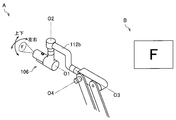
- the arm 104 is, for example, a plurality of links 112a coupled by a plurality of joint portions 110a, 110b, 110c, 110d, 110e, and 110f and joint portions 110a, 110b, 110c, 110d, 110e, and 110f. , 112b, 112c, 112d, 112e, 112f, and 112g.
- the rotatable ranges of the joint portions 110a, 110b, 110c, 110d, 110e, and 110f are arbitrarily set in the design stage, the manufacturing stage, and the like so that the desired movement of the arm 104 is realized.
- first axis O1 and second axis O2 corresponding to the six joint portions 110a, 110b, 110c, 110d, 110e, and 110f that constitute the arm 104.
- the third axis O3, the fourth axis O4, the fifth axis O5, and the sixth axis O6) provide six degrees of freedom for the movement of the imaging device 106. More specifically, in the medical observation apparatus 100 shown in FIG. 1, a motion with 6 degrees of freedom of 3 translational degrees of freedom and 3 degrees of freedom of rotation is realized.
- the first axis O1 is the first rotation axis counted from the side where the imaging device 106 is supported in the arm 104.
- the second axis O2 is the second rotation axis counted from the side where the imaging device 106 is supported on the arm 104.
- the third axis O3 is the third rotation axis counted from the side where the imaging device 106 is supported on the arm 104.
- the fourth axis O4 is the fourth rotation axis counted from the side where the imaging device 106 is supported on the arm 104.
- the fifth axis O5 is the fifth rotation axis counted from the side where the imaging device 106 is supported on the arm 104.
- the sixth axis O6 is the sixth rotation axis as counted from the side where the imaging device 106 is supported on the arm 104.
- each of the joint portions 110a, 110b, 110c, 110d, 110e, and 110f is provided with an actuator (not shown), and each of the joint portions 110a, 110b, 110c, 110d, 110e, and 110f is an actuator (not shown).
- Driving of an actuator (not shown) is controlled by, for example, a processor that functions as a control unit described later, or an external medical control device (not shown).
- an actuator may be provided only in a part of the joint portions 110a, 110b, 110c, 110d, 110e, and 110f.
- An example of a configuration in which an actuator (not shown) is provided only in a part is as follows: “Actuators (not shown) are provided in the joint portions 110a, 110b, and 110c, and actuators (not shown) are provided in the joint portions 110d, 110e, and 110f. A configuration in which a not-shown) is not provided.
- each of the joint portions 110a, 110b, 110c, 110d, 110e, and 110f may be provided with angle sensors (not shown) that can detect the rotation angles of the six rotation axes.
- angle sensors for example, an arbitrary sensor that can obtain rotation angles on each of the six rotation axes, such as a rotary encoder and an angular velocity sensor, can be cited.
- an angle sensor may be provided only in a part of the joint portions 110a, 110b, 110c, 110d, 110e, and 110f.
- An example of a configuration in which an angle sensor (not shown) is provided only in a part is as follows: “An angle sensor (not shown) is provided in the joint portions 110a, 110b, and 110c, and the joint portions 110d, 110e, and 110f include “A configuration in which an angle sensor (not shown) is not provided” may be mentioned.
- the senor provided in the arm 104 is not limited to the angle sensor.
- the arm 104 may be provided with a sensor that detects an external force applied to the arm 104.
- a sensor that detects an external force applied to the arm 104 serves to detect a predetermined input (described later) to the arm 104.
- Examples of the sensor that detects the external force applied to the arm 104 include an arbitrary sensor that can detect a force such as a load cell.
- a sensor that detects an external force applied to the arm 104 in the medical observation apparatus 100 can function as a sensor for detecting the moving direction of the imaging device 106, for example.
- the sensor for detecting the external force applied to the arm 104 is disposed, for example, between the joint portion 110a corresponding to the first axis O1 and the joint portion 110b corresponding to the second axis O2, that is, in the link 112a portion.
- positioning of the sensor which detects the external force added to the arm 104 is not restricted to the example shown above.
- a sensor that detects an external force applied to the arm 104 may be disposed in the link 112b portion.
- each of the joint portions 110a, 110b, 110c, 110d, 110e, and 110f is rotated by a corresponding rotation shaft by driving an actuator (not shown), for example, the arm 104 is extended or contracted (folded).
- Various arm 104 movements are realized.
- various movements of the arm 104 such as extending and contracting (folding) the arm 104 are performed by the joint portions 110a, 110b, 110c, 110d, 110e, and 110f rotating on the corresponding rotation shafts by the operation by the user. It may be realized by doing so.
- the joint portion 110a has a substantially cylindrical shape, and the imaging device 106 (the upper end portion of the imaging device 106 in FIG. 1) is connected to the central axis of the imaging device 106 at the distal end portion (lower end portion in FIG. 1) of the joint portion 110a. It supports so that it can rotate around a parallel rotating shaft (1st axis
- the medical observation apparatus 100 shown in FIG. 1 is configured such that the first axis O1 coincides with the optical axis of the imaging device 106.
- the first axis O1 is coaxial with the optical axis of the imaging device 106. That is, by rotating the imaging device 106 around the first axis O1 illustrated in FIG.
- the medical captured image captured by the imaging device 106 is an image that is changed so that the field of view rotates.
- the configuration of the medical observation apparatus 100 is not limited to the configuration in which the first axis O1 is coaxial with the optical axis of the imaging device 106.
- the link 112a is a substantially rod-like member and fixedly supports the joint portion 110a.
- the link 112a extends in a direction orthogonal to the first axis O1 and is connected to the joint portion 110b.
- the joint portion 110b has a substantially cylindrical shape, and supports the link 112a so as to be rotatable around a rotation axis (second axis O2) orthogonal to the first axis O1. Further, the link 112b is fixedly connected to the joint portion 110b.
- the link 112b is a substantially L-shaped member whose one side extends in a direction orthogonal to the second axis O2, and the joint portion 110b and the joint portion 110c are connected to the link 112b, respectively.
- the joint portion 110c has a substantially cylindrical shape, and supports the link 112b so as to be rotatable at least about a rotation axis (third axis O3) orthogonal to the second axis O2. Further, one end of the link 112c is fixedly connected to the joint portion 110c.
- the position of the imaging device 106 in the horizontal plane is changed by rotating the distal end side (the side on which the imaging device 106 is provided) of the arm 104 about the second axis O2 and the third axis O3.
- the imaging device 106 can be moved. That is, in the medical observation apparatus 100, the visual field of the medical captured image can be moved in a plane by controlling the rotation around the second axis O2 and the third axis O3.
- the link 112c is connected to the link 112b via the joint part 110c, and is connected to the link 112d via the joint part 110d.
- the link 112c is connected to the link 112e.
- the joint portion 110d supports the link 112c so as to be rotatable around a rotation axis (fourth axis O4) orthogonal to the third axis O3.
- a link 112d is connected to the joint portion 110d.
- the link 112d is connected to the link 112c via the joint portion 110d, and is connected to the link 112g via the joint portion 110e.
- the link 112d is connected to the link 112f.
- the link 112e is connected to each of the link 112c and the link 112f.
- the link 112f is connected to each of the link 112d and the link 112e.
- a counterweight 114 is provided at one end of the link 112f.
- the counterweight 114 has a rotational moment generated around the fourth axis O4 and a circumference around the fifth axis O5 due to the mass of each component provided on the tip side of the arm 104 (the side where the imaging device 106 is provided) from the counterweight 114.
- the mass and the arrangement position are adjusted so that the rotational moment generated in the can be offset.
- the joint portion 110e supports one end of the link 112d so as to be rotatable around a rotation axis (fifth axis O5) parallel to the fourth axis O4.
- One end of a link 112g is connected to the joint part 110e.
- the fourth axis O4 and the fifth axis O5 are rotation axes capable of moving the imaging device 106 in the vertical direction.
- the position of the imaging device 106 in the vertical direction changes as the distal end side (side on which the imaging device 106 is provided) of the arm 104 rotates around the fourth axis O4 and the fifth axis O5. Therefore, the distal end side of the arm 104 (the side on which the imaging device 106 is provided) rotates around the fourth axis O4 and the fifth axis O5, whereby the distance between the imaging device 106 and an observation target such as a surgical site of the patient. Can be changed.
- the link 112g extends vertically downward from a first member having a substantially L shape in which one side extends in the vertical direction and the other side extends in the horizontal direction, and a portion extending in the horizontal direction of the first member.
- the rod-shaped second member is a member configured in combination.
- the joint portion 110e is fixedly connected to a portion of the link 112g that extends in the vertical direction of the first member.
- the joint portion 110f is connected to the second member of the link 112g.
- the link 112f and the base 102 are connected to the joint part 110f.
- the joint part 110f supports the link 112g so as to be rotatable around a rotation axis (sixth axis O6) parallel to the vertical direction.
- the medical observation apparatus 100 realizes six degrees of freedom with respect to the movement of the imaging device 106.
- the configuration of the arm 104 is not limited to the example shown above.
- FIG. 1 shows a configuration in which the counterweight 114 is provided in the arm 104, that is, a configuration in which the arm 104 is a balance arm, but the arm 104 may have a configuration in which the counterweight 114 is not provided.
- each of the joint portions 110a, 110b, 110c, 110d, 110e, and 110f of the arm 104 may be provided with a brake that restricts the rotation of each of the joint portions 110a, 110b, 110c, 110d, 110e, and 110f.
- a brake that restricts the rotation of each of the joint portions 110a, 110b, 110c, 110d, 110e, and 110f.
- Examples of the brake according to the present embodiment include an arbitrary brake such as a mechanically driven brake and an electrically driven electromagnetic brake.
- the driving of the brake is controlled by, for example, a processor that functions as a control unit, which will be described later, or an external medical control device (not shown).
- the operation mode of the arm 104 is set. Examples of the operation mode of the arm 104 include a fully fixed mode, a partially fixed mode, and a free mode.
- the all-fixed mode is an operation mode in which, for example, the position and orientation of the imaging device 106 are fixed by restricting rotation of each rotation shaft provided in the arm 104 by a brake. .
- the operation state of the medical observation apparatus 100 becomes a fixed state in which the position and posture of the imaging device 106 are fixed.
- the partially fixed mode is, for example, that the position and orientation of the imaging device 106 are partially fixed by restricting rotation on a part of the rotation shaft provided in the arm 104 by a brake. It is an operation mode.
- the rotation operation on the second axis O2 and the third axis O3 is possible, and the rotation operation on the other axes is limited.
- the example of restriction when the partially fixed mode is set is not limited to the example described above.
- the free mode according to the present embodiment is an operation mode in which each rotation shaft provided in the arm 104 can freely rotate when the brake is released.
- the position and posture of the imaging device 106 can be adjusted by a direct operation by an operator.
- the direct operation according to the present embodiment means, for example, an operation in which the surgeon holds the imaging device 106 by hand and directly moves the imaging device 106.
- Imaging Device 106 The imaging device 106 is supported by the arm 104 and images an observation target such as a surgical site of a patient. Imaging in the imaging device 106 is controlled by, for example, a processor that functions as a control unit, which will be described later, or an external medical control device (not shown).
- the imaging device 106 has a configuration corresponding to, for example, an electronic imaging microscope.
- FIG. 3 is an explanatory diagram for explaining an example of the configuration of the imaging device 106 provided in the medical observation apparatus 100 according to the present embodiment.
- FIG. 3 shows a case where the first axis O1 and the optical axis of the imaging device 106 are coaxial, and the optical axis of the imaging device 106 faces downward in the vertical direction.
- 3 includes, for example, an imaging member 120 and a cylindrical member 122 having a substantially cylindrical shape, and the imaging member 120 is provided in the cylindrical member 122.
- the cover glass (not shown) for protecting the imaging member 120 is provided in the opening surface of the lower end (lower end in FIG. 3) of the cylindrical member 122, for example.
- a light source (not shown) is provided inside the cylindrical member 122, and illumination light is emitted from the light source to the subject through the cover glass during imaging. Reflected light (observation light) from a subject irradiated with illumination light enters the imaging member 120 through a cover glass (not shown), whereby an image signal (medical imaging image) indicating the subject by the imaging member 120 is obtained. Is obtained).
- the imaging member 120 it is possible to apply a configuration used in various known electronic imaging microscope units.
- the imaging member 120 includes, for example, an optical system 120a and an image sensor 120b including an imaging element that captures an image to be observed with light that has passed through the optical system 120a.
- the optical system 120a includes, for example, one or more lenses such as an objective lens, a zoom lens, and a focus lens, and an optical element such as a mirror.
- Examples of the image sensor 120b include an image sensor using a plurality of imaging elements such as a CMOS (Complementary Metal Oxide Semiconductor) and a CCD (Charge Coupled Device).
- CMOS Complementary Metal Oxide Semiconductor
- CCD Charge Coupled Device
- the imaging member 120 functions as a so-called stereo camera by having two or more imaging devices including the optical system 120a and the image sensor 120b.
- the imaging device constituting the imaging member 120 is generally provided in an electronic imaging microscope unit such as a zoom function (one or both of an optical zoom function and an electronic zoom function) and an AF (Auto Focus) function. Or two or more functions are installed.
- an electronic imaging microscope unit such as a zoom function (one or both of an optical zoom function and an electronic zoom function) and an AF (Auto Focus) function. Or two or more functions are installed.
- the imaging member 120 may have a configuration capable of imaging at a so-called high resolution such as 4K or 8K. Since the imaging member 120 is configured to be capable of imaging at a high resolution, a display device 200 having a large display screen of, for example, 50 inches or more while ensuring a predetermined resolution (for example, Full HD image quality). Since the image can be displayed on the screen, the visibility of the operator who views the display screen is improved. In addition, since the imaging member 120 is configured to be capable of imaging at a high resolution, even if the captured image is enlarged by the electronic zoom function and displayed on the display screen of the display device 200, a predetermined resolution is ensured. Is possible.
- the performance of the optical zoom function in the imaging device 106 can be suppressed, so that the optical system of the imaging device 106 can be simplified.
- the imaging device 106 can be configured more compactly.
- the imaging device 106 is provided with various operation devices for controlling the operation of the imaging device 106, for example.
- the zoom switch 124, the focus switch 126, and the operation mode setting switch 128 are provided in the imaging device 106.
- the position and shape of the zoom switch 124, the focus switch 126, and the operation mode setting switch 128 are not limited to the example shown in FIG.
- the zoom switch 124 and the focus switch 126 are examples of operation devices for adjusting the imaging conditions in the imaging device 106.
- the zoom switch 124 includes, for example, a zoom-in switch 124a that increases the zoom magnification (enlargement ratio) and a zoom-out switch 124b that decreases the zoom magnification. By operating the zoom switch 124, the zoom magnification is adjusted and the zoom is adjusted.
- the focus switch 126 includes, for example, a distant focus switch 126a that increases the focal distance to the observation target (subject) and a foreground focus switch 126b that decreases the focal distance to the observation target. By operating the focus switch 126, the focal length is adjusted and the focus is adjusted.
- the operation mode setting switch 128 is an example of an operation device for setting the operation mode of the arm 104 in the imaging device 106. By operating the operation mode setting switch 128, the operation mode of the arm 104 is changed. Examples of the operation mode that is changed by performing an operation on the operation mode setting switch 128 include a fully fixed mode and a free mode. That is, the operation mode setting switch 128 is an example of an operation device (first operation device) that can perform an operation for limiting all the degrees of freedom of the arm 104.
- An example of an operation on the operation mode setting switch 128 is an operation of pressing the operation mode setting switch 128.
- the operation mode of the arm 104 is the free mode, and when the surgeon is not pressing the operation mode setting switch 128, the operation mode of the arm 104 is all fixed. It becomes a mode.
- the imaging device 106 is provided with, for example, a non-slip member 130 and a protruding member 132 in order to further improve operability and convenience when an operator who performs operations on various operation devices performs the operation. .
- the anti-slip member 130 is a member provided to prevent the operating body from slipping when the operator operates the cylindrical member 122 with an operating body such as a hand.
- the anti-slip member 130 is formed of, for example, a material having a large friction coefficient, and has a structure that is more difficult to slip, such as unevenness.
- the protruding member 132 may block the visual field of the optical system 120a or be operated with the operating body.
- the cover glass (not shown) is a member provided to prevent the cover glass from becoming dirty when the operating body touches the cover glass.
- the position and shape of the anti-slip member 130 and the protruding member 132 are not limited to the example shown in FIG. Further, the imaging device 106 may not be provided with one or both of the anti-slip member 130 and the protruding member 132.
- the image signal (image data) generated by imaging in the imaging device 106 is subjected to image processing, for example, in a processor that functions as a control unit described later.
- image processing for example, one or more processes among various processes such as gamma correction, white balance adjustment, image enlargement or reduction, or inter-pixel correction related to the electronic zoom function. Is mentioned.
- the medical observation system according to the present embodiment includes a medical control device (not shown) that controls various operations in the medical observation device 100
- the image processing according to the present embodiment is performed by the medical treatment device. It may be performed in a control device (not shown).
- the medical observation apparatus 100 transmits, for example, a display control signal and an image signal subjected to the image processing as described above to the display apparatus 200.
- a medical captured image (for example, a captured image in which the surgical site is captured) is captured on the display screen of the display device 200.
- the image is enlarged or reduced to a desired magnification by one or both of the optical zoom function and the electronic zoom function.
- the configuration of the imaging device 106 is not limited to the example shown in FIG.
- FIG. 4 is an explanatory diagram for explaining another example of the configuration of the imaging device 106 provided in the medical observation apparatus 100 according to the present embodiment.
- FIG. 4 shows a case where the first axis O1 and the optical axis of the imaging device 106 are coaxial, and the optical axis of the imaging device 106 is directed downward in the vertical direction.
- the imaging device 106 shown in FIG. 4 has basically the same configuration as the imaging device 106 shown in FIG. The difference between the imaging device 106 shown in FIG. 4 and the imaging device 106 shown in FIG. 3 is that the imaging device 106 shown in FIG. 4 further includes operation mode setting switches 134 and 136.
- the operation mode setting switches 134 and 136 are other examples of the operation device for setting the operation mode of the arm 104 in the imaging device 106. By operating both the operation mode setting switches 134 and 136, the operation mode of the arm 104 is set to the partially fixed mode. That is, the operation mode setting switches 134 and 136 are an example of an operation device (second operation device) that can perform an operation for limiting the degree of freedom of a part of the arm 104.
- two switches operation mode setting switches 134 and 136, are shown as operation devices that can perform an operation for limiting the degree of freedom of a part of the arm 104.
- One switch may be sufficient as the operation device which can perform operation which restrict
- An example of an operation on the operation mode setting switches 134 and 136 is an operation of pressing the operation mode setting switches 134 and 136.
- the operation mode of the arm 104 is a partially fixed mode.
- the rotation operation on the second axis O2 and the third axis O3 is possible, and the rotation operation on the other axes is limited.
- the operation mode of the arm 104 depends on the state of operation on the operation mode setting switch 128.
- the operation mode of the arm 104 is a free mode.
- the operation mode of the arm 104 may be a partially fixed mode.
- the operation mode setting switch 128 (an example of a first operation device; hereinafter the same) and the operation mode setting switches 134 and 136 (an example of a second operation device) are imaged.
- the device 106 is arranged so that it is arranged up and down when the optical axis of the device 106 is directed downward in the vertical direction. Specifically, when the optical axis of the imaging device 106 is directed downward in the vertical direction, the operation mode setting switches 134 and 136 are disposed below the operation mode setting switch 128.
- the operation mode setting switch 128 and the operation mode setting switches 134 and 136 are arranged as shown in FIG. 4, the following is realized by the operation of the surgeon.
- the surgeon holds the imaging device 106 so that both the operation mode setting switch 128 and the operation mode setting switches 134 and 136 are pressed. Since the operation mode of the arm 104 is a free mode, the operator moves the imaging device 106 so that a desired imaging range is imaged. The surgeon loosens the index finger and stops the operation on the operation mode setting switch 128.
- the operation mode of the arm 104 is a partially fixed mode, and the movement of the arm 104 in the focus direction is restricted.
- the surgeon performs fine adjustment of the imaging range in a state where movement of the arm 104 in the focus direction is restricted, and releases the hand from the imaging device 106 when the fine adjustment is completed. Since the operation mode of the arm 104 is the all-fixed mode, the imaging range of the imaging device 106 is fixed.
- the focus does not shift, so the surgeon does not need to hold the imaging device 106 firmly. Therefore, the operator can finely adjust the imaging range using a hand having a medical instrument such as forceps. Therefore, the medical observation apparatus 100 including the imaging device 106 illustrated in FIG. 4 can improve convenience for a user such as an operator.
- the medical observation apparatus 100 has a hardware configuration shown with reference to, for example, FIGS.
- the hardware configuration of the medical observation apparatus according to the present embodiment is not limited to the configuration shown with reference to FIGS. 1, 3, and 4.
- the medical observation apparatus according to the present embodiment may have a configuration in which the arm 104 is directly attached to a ceiling or a wall surface of an operating room or the like without including the base 102.
- the medical observation apparatus according to the present embodiment has a configuration in which the arm 104 is suspended from the ceiling.
- FIG. 1 shows an example in which the arm 104 is configured to realize six degrees of freedom regarding the driving of the imaging device 106, but the configuration of the arm 104 is a degree of freedom regarding the driving of the imaging device 106. Is not limited to a configuration with 6 degrees of freedom.
- the arm 104 only needs to have three or more degrees of freedom including the degrees of freedom realized by the rotation operation on the first axis O1, the second axis O2, and the third axis O3.
- the number and arrangement of the joints and links, the direction of the drive shaft of the joints, and the like can be set as appropriate so that the arm 104 has three or more degrees of freedom.
- FIGS. 1, 3, and 4 illustrate examples in which various operation devices for controlling the operation of the imaging device 106 are provided in the imaging device 106
- FIGS. 1, 3, and 4 illustrate the example. Some or all of the operation devices shown may not be provided in the imaging device 106.
- various operation devices for controlling the operation of the imaging device 106 may be provided in a part other than the imaging device 106 constituting the medical observation apparatus according to the present embodiment.
- the various operation devices for controlling the operation of the imaging device 106 may be any external operation device such as a foot switch or a hand switch such as a remote controller.
- the imaging device 106 may be configured to be able to switch between a plurality of observation modes.
- an observation mode for example, an observation mode in which imaging is performed with natural light, an observation mode in which imaging is performed with special light, and an observation mode in which imaging is performed using an image enhancement observation technique such as NBI (Narrow Band Imaging).
- the special light according to this embodiment is, for example, light in a specific wavelength band such as light in the near-infrared wavelength band or light in the fluorescence wavelength band of fluorescence observation using 5-ALA (5-Aminolevulinic Acid). is there.
- the imaging device 106 capable of switching a plurality of observation modes, for example, “a filter that transmits light in a specific wavelength band and does not transmit light in other wavelength bands, and the filter on the optical path” And a moving mechanism that is selectively disposed on the device.
- a near-infrared wavelength band for example, a wavelength band of about 0.7 [micrometer] to 2.5 [micrometer]
- 5- Fluorescence wavelength band by fluorescence observation using ALA for example, wavelength band of about 0.6 [micrometer] to 0.65 [micrometer]
- ICG Indocyanine Green fluorescence wavelength band
- the imaging device 106 may be provided with a plurality of filters having different wavelength bands to be transmitted. Further, in the above description, an example in which imaging is performed with light of a specific wavelength band by arranging a filter on the optical path has been described, but the configuration of the imaging device 106 for imaging with light of a specific wavelength band However, it goes without saying that the present invention is not limited to the example described above.
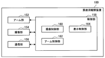
- FIG. 5 is a functional block diagram showing an example of the configuration of the medical observation apparatus 100 according to the present embodiment.
- the medical observation apparatus 100 includes, for example, an arm unit 152, an imaging unit 154, a communication unit 156, and a control unit 158.
- the arm unit 152 includes the arm 104 and supports the imaging device 106 that configures the imaging unit 154.
- the imaging unit 154 includes the imaging device 106 and images an observation target. Imaging in the imaging unit 154 is controlled by the control unit 158, for example.
- the communication unit 156 is a communication unit included in the medical observation apparatus 100 and serves to communicate with an external apparatus such as the display apparatus 200 wirelessly or by wire.
- the communication unit 156 includes, for example, the communication device (not shown) described above. Communication in the communication unit 156 is controlled by the control unit 158, for example.
- the control unit 158 includes, for example, the above-described processor (not shown), and serves to control the entire medical observation apparatus 100.
- the control unit 158 plays a role of performing a process related to a control method to be described later. Note that the processing related to the control method in the control unit 158 may be performed in a distributed manner by a plurality of processing circuits (for example, a plurality of processors).
- control unit 158 includes, for example, an imaging control unit 160, an arm control unit 162, and a display control unit 164.
- the imaging control unit 160 controls the imaging device 106 that constitutes the imaging unit 154.
- the control of the imaging device 106 for example, one or two or more functions that are generally provided in a microscope section of an electronic imaging type, such as control of an AF function including at least a zoom function (optical zoom function and electronic zoom function). Control is mentioned.
- the arm control unit 162 controls driving of the arm 104 constituting the arm unit 152.
- a control signal for controlling the drive is applied to an actuator (not shown) corresponding to each of the joint portions 110a, 110b, 110c, 110d, 110e, and 110f. "".
- the arm control unit 162 serves to perform processing related to a control method described later. An example of processing related to the control method according to the present embodiment will be described later.
- the display control unit 164 transmits the display control signal and the image signal to a communication device (not shown) that configures the communication unit 156, and causes the display device 200 to transmit the display control signal and the image signal.
- a communication device not shown
- communication control in the communication unit 156 may be performed by a communication control unit (not shown) constituting the control unit 158.
- the display control unit 164 can also serve to perform a process related to the control method according to the present embodiment.
- the control unit 158 has, for example, the arm control unit 162, and plays a role of leading the processing related to the control method according to the present embodiment.
- the control unit 158 has, for example, the imaging control unit 160, the arm control unit 162, and the display control unit 164, thereby serving to control the entire medical observation apparatus 100.
- control unit 158 is not limited to the example shown in FIG.
- control unit 158 can have an arbitrary configuration according to how the functions of the medical observation apparatus 100 are divided, such as a configuration according to a method of dividing a process according to the control method according to the present embodiment. is there.
- the medical observation apparatus 100 performs a process related to a control method according to the present embodiment, which will be described later, with the configuration illustrated in FIG.
- the medical observation apparatus includes a part or all of the imaging control unit 160, the arm control unit 162, and the display control unit 164 illustrated in FIG. 5 separately from the control unit 158 ( For example, it can be realized by another processing circuit).
- the functional configuration for realizing the processing according to the control method according to the present embodiment in the medical observation apparatus according to the present embodiment is not limited to the configuration illustrated in FIG. 5, for example, the medical observation according to the present embodiment.
- the apparatus can have a functional configuration corresponding to a process classification according to the control method according to the present embodiment.
- the medical observation apparatus when communication with an external device is performed via an external communication device having the same function and configuration as the communication unit 156, the medical observation apparatus according to the present embodiment does not include the communication unit 156. May be.
- the medical observation system according to the present embodiment has a configuration having a medical control device (not shown), and the medical observation device according to the present embodiment is controlled by the medical control device (not shown).
- the medical observation apparatus according to this embodiment may not include the control unit 158.
- the medical control device includes, for example, a control unit having the same function and configuration as the control unit 158, thereby performing processing related to the control method according to the present embodiment described later.
- the operation of each component such as the arm unit 152 and the imaging unit 154 included in the medical observation apparatus according to this embodiment is controlled.
- the medical control apparatus (not shown) communicates with the medical observation apparatus according to the present embodiment via a communication device that is provided or an external communication device that is connected.
- movement in each component with which the medical observation apparatus which concerns on is equipped is controlled.
- the medical observation system according to the present embodiment has a configuration having a medical control device (not shown), and the medical observation device according to the present embodiment is controlled by the medical control device (not shown).
- the medical observation apparatus according to the present embodiment can have a configuration that does not have some functions of the control unit 158.
- FIG. 6 is an explanatory diagram for explaining the outline of the control method according to the present embodiment.
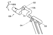
- FIG. 6A shows a first example of the posture of the arm 104.
- 6B shows a second example of the posture of the arm 104, and
- FIG. 6C shows a third example of the posture of the arm 104.
- the first axis O1, the second axis O2, and the third axis O3 are in an orthogonal state.
- the medical observation image is rotated by the rotation operation on the first axis O1
- the imaging range of the imaging device 106 is moved in the vertical direction (vertical direction; hereinafter the same applies) by the rotation operation on the second axis O2.
- the imaging range of the imaging device 106 moves in the left-right direction (a direction perpendicular to the vertical direction; the same shall apply hereinafter) by the rotation operation on the third axis O3.
- the degree of freedom does not decrease and the degree of freedom is not insufficient.
- the posture according to the second example shown in B of FIG. 6 is a posture in which the second axis O2 is rotated by 90 [°] from the posture according to the first example shown in A of FIG.
- the medical observation image is rotated by the rotation operation on the first axis O1 and the rotation operation on the third axis O3.
- the imaging range of the imaging device 106 moves in the vertical direction by the rotation operation on the second axis O2
- the imaging range of the imaging device 106 is moved in the horizontal direction in the posture according to the second example illustrated in FIG.
- the posture according to the third example shown in C of FIG. 6 is a posture in which the first axis O1 and the third axis O3 are rotated by 90 [°] from the posture according to the second example shown in B of FIG.
- the medical observation image is rotated by the rotation operation on the first axis O1 and the rotation operation on the third axis O3.
- the imaging range of the imaging device 106 moves in the left-right direction by the rotation operation on the second axis O2
- the imaging range of the imaging device 106 is moved in the vertical direction in the posture according to the third example illustrated in FIG.
- a user such as a surgeon manually moves the link 112b to the third axis. If the rotation is performed around O3, a desired degree of freedom of rotation can be obtained by the relative rotation of the second axis O2. However, when the link 112b is manually rotated around the third axis O3, the user may need to perform an operation using both hands, and the user may feel annoyed.
- the medical observation apparatus 100 has some degrees of freedom depending on the posture of the arm 104, such as the posture according to the second example shown in B of FIG. 6 and the posture according to the third example shown in C of FIG. Even in the case where the loss is lost, the degree of freedom is automatically secured by controlling the operation of the arm 104. More specifically, the medical observation apparatus 100 controls the operation of the arm 104 and detects the existing one when the input to move the arm 104 to the degree of freedom determined to be lost is detected. The degree of freedom is automatically secured by actively controlling the degree of freedom.
- the medical observation apparatus 100 can improve the convenience of the user who uses the medical observation apparatus 100.
- the medical observation apparatus 100 controls the operation of the arm 104 to control the existing free movement when an input to move the arm 104 to the degree of freedom determined to be lost is detected. Actively control the degree.
- the medical observation apparatus 100 specifies the posture of the arm 104 (or estimates the posture of the arm 104 based on the rotation angle of each rotation axis in the medical observation device 100. The same applies hereinafter. ) Is possible.
- the method for specifying the posture of the arm 104 is not limited to the example described above, and the medical observation apparatus 100 can use any method that can specify the posture of the arm 104.
- the posture of the arm 104 may be specified.
- an input to move the arm 104 to the degree of freedom determined to be lost means “the posture of the arm 104 is in a predetermined state and the second axis O2 and the third axis This is an input for moving the arm 104 around a rotation axis orthogonal to O3.
- the posture of the arm 104 according to the present embodiment is in a predetermined state, for example, the posture according to the second example shown in B of FIG. 6 and the posture according to the third example shown in C of FIG. “The first axis O1 is on a plane defined by the second axis O2 and the third axis O3” or “the first axis O1 is the second axis O2 and the third axis O3” It is in a state that exists on a plane parallel to the plane defined by.
- the medical observation apparatus 100 determines whether or not the posture of the arm 104 is in a predetermined state by checking the relationship between the first axis O1, the second axis O2, and the third axis O3 in the posture of the specified arm 104. Determine.
- the method for determining whether the posture of the arm 104 is in a predetermined state is not limited to the example described above.
- the medical observation apparatus 100 determines that the posture of the arm 104 is in a predetermined state when an input for moving the arm 104 around a rotation axis orthogonal to the second axis O2 and the third axis O3 is detected. May be.
- the predetermined state is determined as described above, for example, when the imaging device 106 is to be moved in a direction in which the surgeon is difficult to move, the medical observation apparatus 100 moves the imaging device 106 by the surgeon. Can assist. Further, the movement of the imaging device 106 is assisted by the medical observation apparatus 100, so that the surgeon can move the imaging device 106 with a smaller force.
- Examples of the input according to the present embodiment include “an external force detected by a sensor that detects an external force applied to the arm 104 such as a load cell” and “an operation signal corresponding to an operation on an external operation device such as a foot switch FS”. Or both.
- an external force detected by a sensor that detects an external force applied to the arm 104 such as a load cell
- an operation signal corresponding to an operation on an external operation device such as a foot switch FS”.
- the case where the “input for moving the arm 104 around the rotation axis orthogonal to the second axis O2 and the third axis O3” is indicated as “predetermined input”. There is.
- the predetermined input includes “an input for moving the arm 104 so as to move the imaging range of the imaging device 106 in the left-right direction”. Further, taking the posture according to the third example shown in FIG. 6C as an example, the predetermined input is “an input for moving the arm 104 so as to move the imaging range of the imaging device 106 in the vertical direction”. It is done.
- the medical observation apparatus 100 rotates the link corresponding to the third axis O3 around the third axis O3 when a predetermined input is detected in the specified posture.
- the link corresponding to the third axis O3 according to the present embodiment is a link that moves directly by the rotation operation on the third axis O3, and corresponds to the link 112b in the arm 104 having the configuration shown in FIG. .
- the medical observation apparatus 100 rotates the link 112b (an example of a link corresponding to the third axis O3; hereinafter the same), or rotates the link 112b counterclockwise.
- the medical observation apparatus 100 may rotate the link 112b in a preset rotation direction, or may rotate the link 112b in a rotation direction determined according to a predetermined rule such as random. .
- the medical observation apparatus 100 may rotate the link 112b in a rotation direction in which the distance from the object is further increased after the link 112b is rotated.
- the medical observation apparatus 100 rotates the link 112b at a rotation speed set in advance, or rotates the link 112b at a rotation speed corresponding to a predetermined input size.
- the medical observation apparatus 100 is, for example, “a table (or database) in which the magnitude of the external force is associated with the rotation speed” (a predetermined input is an external force detected by a sensor that detects the external force applied to the arm 104. Or a “table (or database) in which the operation amount indicated by the operation signal is associated with the rotation speed”.
- the rotation speed corresponding to the magnitude of the predetermined input is specified using (when the predetermined input is an operation signal corresponding to an operation on an external operation device).
- Data indicating the rotation speed set in advance and each of the above tables are stored in, for example, a recording medium functioning as a storage unit (not shown).
- the medical observation apparatus 100 may specify the rotation speed corresponding to the predetermined input size by performing an arithmetic operation using an arbitrary algorithm that can obtain the rotation speed from the predetermined input size. Good.
- FIG. 7 and 8 are explanatory diagrams illustrating an example of processing related to the control method according to the present embodiment.
- the posture of the arm 104 shown in FIG. 7A is the same as the posture according to the third example shown in C of FIG. 7 shows an example of a medical captured image displayed on the display screen of the display device 200.
- the posture of the arm 104 shown in FIG. 8 is the same as the posture according to the second example shown in B of FIG.
- the first axis O1 is on a plane defined by the second axis O2 and the third axis O3
- the posture of the arm 104 is in a predetermined state
- the medical observation apparatus 100 rotates the third axis O3.
- An actuator (not shown) to be driven is driven to rotate the link 112b.
- the medical observation is performed.
- the apparatus 100 drives an actuator (not shown) that rotates the third axis O3 to rotate the link 112b.
- the posture of the arm 104 is as shown in FIG.
- the imaging range of the imaging device 106 is moved in the vertical direction by the rotation operation on the second axis O2. be able to. Therefore, when the medical observation apparatus 100 rotates the link 112b as shown with reference to FIGS. 7 and 8, for example, the operator can manually change the posture of the arm 104 without changing the posture of the arm 104.
- the imaging device 106 can be moved.
- the medical observation apparatus 100 performs, for example, a process according to the first example shown in (1) below and a process related to the second example shown in (2) below as processes related to the control method according to the present embodiment. One or both of the above may be performed.
- 9 and 10 are explanatory diagrams for explaining an example of processing related to the control method according to the present embodiment.
- 9A and 10A show a medical observation apparatus 100 having a configuration similar to that in FIG. 1, and a foot switch FS is also shown as an example of an external operation device.
- 9B, FIG. 10B, and FIG. 10C illustrate an example of a medical captured image displayed on the display screen of the display device 200.
- the imaging device 106 When the posture of the arm 104 is changed from the posture shown in FIG. 9A to the posture shown in FIG. 10A by rotating the link 112b, the imaging device 106 also rotates indirectly with the rotation of the link 112b. As a result, the medical captured image displayed on the display screen is an image obtained by rotating the medical captured image shown in FIG. 9B as shown in FIG. 10B.
- the medical observation apparatus 100 rotates the link 112b corresponding to the third axis O3 around the third axis O3, the direction of the medical captured image before the rotation around the third axis O3, and the third axis O3.
- the operation of the arm 104 is controlled so that the orientation of the medical captured image after rotation around does not change. More specifically, the medical observation apparatus 100 rotates the first axis O1 so as to cancel the rotation of the medical captured image due to the rotation of the third axis O3.
- the medical captured image displayed on the display screen is shown in FIG.
- the image is the same as the medical captured image shown in FIG. 9B. Therefore, even if the link 112b is rotated, the appearance of the medical captured image does not change, so the possibility that the surgeon feels uncomfortable is reduced.
- the medical observation apparatus 100 may perform image processing that cancels the rotation of the medical captured image due to the rotation of the third axis O3.
- Examples of the image processing include “a process of rotating a medical captured image in the direction opposite to the rotation direction of the third axis O3 with the same rotation amount as the rotation amount of the third axis O3”.
- the image processing is performed by, for example, the display control unit 164.
- the medical observation apparatus 100 rotates the link 112b corresponding to the third axis O3 about the third axis O3, the visual field position shift of the imaging device 106 caused by the rotation of the link 112b corresponding to the third axis O3. Is controlled so as to be corrected.
- the medical observation apparatus 100 is, for example, a part of the axes other than the first axis O1, the second axis O2, and the third axis O3, that is, the fourth axis O4, the fifth axis O5, and the sixth axis O6. Alternatively, all the axes are rotated, and the positional deviation of the field of view of the imaging device 106 caused by the offset shown in FIG. 9 is corrected.
- the medical observation apparatus 100 corrects the vertical position shift by one or both of the rotation of the fourth axis O4 and the rotation of the fifth axis O5. To do.
- the medical observation apparatus 100 corrects the positional deviation in the left-right direction by rotating the sixth axis O6.
- the center position of the imaging range of the imaging device 106 (the center of the observation visual field) does not move even if the link 112b is rotated by correcting the positional deviation of the visual field of the imaging device 106. Is less likely to feel uncomfortable.
- the medical observation apparatus 100 may have a configuration in which the offset shown in FIG. 9 is sufficiently small, for example.
- Making the offset shown in FIG. 9 sufficiently small includes that there is no offset shown in FIG. 9 and that the offset is so small that the field of view of the imaging device 106 does not make the operator feel uncomfortable. It is.
- FIG. 11 is an explanatory diagram illustrating an example of the configuration of the medical observation apparatus 100 according to the present embodiment, and illustrates an example of a configuration in which the offset illustrated in FIG. 9 is sufficiently small.
- a foot switch FS is also shown as an example of an external operation device, as in FIGS.
- the first axis O1 and the third axis O3 are coaxial with each other due to the shape of the link 112b, for example, and the offset shown in FIG. 9 does not exist. Therefore, in the medical observation apparatus 100 having the configuration shown in FIG. 11, even if the link 112b is rotated, the center position of the imaging range of the imaging device 106 (the center of the observation visual field) does not move, so the operator feels uncomfortable. The possibility is reduced.
- the surgeon can move the imaging device 106 with a smaller amount of force.
- the surgeon can move the imaging device 106 to a desired position while holding the treatment tool in his hand, for example.
- the program is executed by a processor or the like in the computer system, so that the convenience of the user using the medical observation apparatus can be improved.
- the computer system according to the present embodiment includes a single computer or a plurality of computers.
- a series of processing related to the control method according to the present embodiment is performed by the computer system according to the present embodiment.
- the above-described embodiment is implemented by causing a computer system to execute a program for causing a computer system to function as the medical observation apparatus according to the present embodiment (or the control apparatus according to the present embodiment).
- the effect exhibited by the display realized by the process according to the control method according to the embodiment can be achieved.
- a program for causing a computer system to function as the medical observation apparatus according to the present embodiment is provided.
- the present embodiment further stores the program. Recording media can also be provided.
- the arm control unit includes a second axis that is a second rotation axis when counted from the side where the imaging device is supported in the arm, and the imaging in the arm.
- a link corresponding to the third axis when a predetermined input is detected that moves the arm around a rotation axis that is orthogonal to the third axis that is the third rotation axis counted from the side on which the device is supported.
- a medical observation apparatus that rotates the lens around the third axis.
- the predetermined state is: The first axis, which is the first rotation axis counted from the side on which the imaging device is supported in the arm, is on a plane defined by the second axis and the third axis, or , The medical observation apparatus according to (1), wherein the first axis is on a plane parallel to a plane defined by the second axis and the third axis. (3) The medical observation apparatus according to (1) or (2), wherein the predetermined input is the external force detected by a sensor that detects an external force applied to the arm. (4) The sensor is disposed between a joint corresponding to the first axis that is the first rotation axis counted from the side on which the imaging device is supported in the arm and a joint corresponding to the second axis.
- the medical observation apparatus according to (3).
- the medical observation apparatus according to any one of (1) to (4), wherein the predetermined input is an operation signal corresponding to an operation on an external operation device.
- the arm control unit is configured to detect a direction of a medical captured image captured by the imaging device before rotation about the third axis and a medical captured image captured by the imaging device after rotation about the third axis.
- the medical observation apparatus according to any one of (1) to (5), wherein the operation of the arm is controlled so that the orientation does not change.
- the arm control unit rotates the first axis, which is the first rotation axis counted from the side where the imaging device is supported in the arm, so as to cancel the rotation of the medical imaging image due to the rotation of the third axis.
- the medical observation apparatus according to (6).
- the arm control unit controls the operation of the arm so that the displacement of the field of view of the imaging device caused by the rotation of the link corresponding to the third axis is corrected. Any one of (1) to (7) The medical observation apparatus as described in any one.
- the medical observation apparatus as described in one.
- the first axis which is the first rotation axis counted from the side on which the imaging device is supported in the arm, is coaxial with the optical axis of the imaging device, and is any one of (1) to (9)
- the arm rotates the second axis so that the first axis, which is the first rotation axis counted from the side on which the imaging device is supported in the arm, and the third axis are coaxial.
- the medical observation apparatus according to any one of (1) to (7), (9), and (10). (12)
- a first operating device capable of operating to limit all the degrees of freedom of the arm;
- a second operating device capable of operating to limit the degree of freedom of a part of the arm; Is provided,
- the first operation device and the second operation device are arranged so as to be arranged one above the other when the optical axis of the imaging device is directed downward in the vertical direction.
- the medical observation apparatus according to any one of 11).
Landscapes
- Health & Medical Sciences (AREA)
- Life Sciences & Earth Sciences (AREA)
- Surgery (AREA)
- Engineering & Computer Science (AREA)
- Heart & Thoracic Surgery (AREA)
- Public Health (AREA)
- Nuclear Medicine, Radiotherapy & Molecular Imaging (AREA)
- Biomedical Technology (AREA)
- Veterinary Medicine (AREA)
- Medical Informatics (AREA)
- Molecular Biology (AREA)
- Animal Behavior & Ethology (AREA)
- General Health & Medical Sciences (AREA)
- Physics & Mathematics (AREA)
- Oral & Maxillofacial Surgery (AREA)
- Pathology (AREA)
- General Physics & Mathematics (AREA)
- Signal Processing (AREA)
- Multimedia (AREA)
- Optics & Photonics (AREA)
- Robotics (AREA)
- Endoscopes (AREA)
- Microscoopes, Condenser (AREA)
- Non-Volatile Memory (AREA)
- Semiconductor Memories (AREA)
Abstract
Le problème décrit par la présente invention est de fournir un instrument d'observation médicale capable d'améliorer la commodité d'emploi pour un utilisateur lors de l'utilisation de l'instrument d'observation médicale. La solution selon l'invention porte sur un instrument d'observation médicale comportant : un bras qui est formé par couplage d'une pluralité de segments l'un à l'autre par l'intermédiaire d'articulations, et qui présente au moins trois degrés de liberté permis par des mouvements de rotation autour d'axes de rotation ; un dispositif d'imagerie supporté par le bras ; et une unité de commande de bras qui commande le mouvement du bras. Lorsque le bras est dans une position prédéterminée et qu'est détectée une entrée prédéterminée visant à amener le bras à se déplacer autour d'un axe de rotation orthogonal à un deuxième axe, qui est le deuxième axe de rotation depuis le côté du bras où le dispositif d'imagerie est supporté, et à un troisième axe, qui est le troisième axe de rotation depuis le côté du bras où le dispositif d'imagerie est supporté, l'unité de commande de bras amène un segment correspondant au troisième axe à tourner autour du troisième axe.
Priority Applications (5)
| Application Number | Priority Date | Filing Date | Title |
|---|---|---|---|
| US16/970,951 US11510751B2 (en) | 2018-02-27 | 2019-01-30 | Medical observation apparatus |
| JP2020502880A JP7208972B2 (ja) | 2018-02-27 | 2019-01-30 | 医療用観察装置 |
| CN201980014378.8A CN111757713A (zh) | 2018-02-27 | 2019-01-30 | 医疗观察设备 |
| EP19759965.7A EP3735934A4 (fr) | 2018-02-27 | 2019-01-30 | Instrument d'observation médicale |
| US17/324,413 US20210280598A1 (en) | 2018-02-27 | 2021-05-19 | Memory device |
Applications Claiming Priority (2)
| Application Number | Priority Date | Filing Date | Title |
|---|---|---|---|
| JP2018032865 | 2018-02-27 | ||
| JP2018-032865 | 2018-02-27 |
Related Child Applications (1)
| Application Number | Title | Priority Date | Filing Date |
|---|---|---|---|
| US17/324,413 Continuation US20210280598A1 (en) | 2018-02-27 | 2021-05-19 | Memory device |
Publications (1)
| Publication Number | Publication Date |
|---|---|
| WO2019167528A1 true WO2019167528A1 (fr) | 2019-09-06 |
Family
ID=67805744
Family Applications (1)
| Application Number | Title | Priority Date | Filing Date |
|---|---|---|---|
| PCT/JP2019/003206 WO2019167528A1 (fr) | 2018-02-27 | 2019-01-30 | Instrument d'observation médicale |
Country Status (5)
| Country | Link |
|---|---|
| US (2) | US11510751B2 (fr) |
| EP (1) | EP3735934A4 (fr) |
| JP (1) | JP7208972B2 (fr) |
| CN (1) | CN111757713A (fr) |
| WO (1) | WO2019167528A1 (fr) |
Cited By (3)
| Publication number | Priority date | Publication date | Assignee | Title |
|---|---|---|---|---|
| CN112530970A (zh) * | 2019-09-17 | 2021-03-19 | 铠侠股份有限公司 | 半导体存储装置 |
| CN113497048A (zh) * | 2020-03-19 | 2021-10-12 | 铠侠股份有限公司 | 半导体存储装置 |
| EP3991685A1 (fr) * | 2020-11-03 | 2022-05-04 | Leica Instruments (Singapore) Pte. Ltd. | Système de microscope chirurgical |
Families Citing this family (4)
| Publication number | Priority date | Publication date | Assignee | Title |
|---|---|---|---|---|
| CN114981967A (zh) * | 2020-01-17 | 2022-08-30 | 株式会社半导体能源研究所 | 半导体装置、半导体装置的驱动方法及电子设备 |
| US20220113487A1 (en) * | 2020-10-09 | 2022-04-14 | Nikon Corporation | Balanced active stabilizers |
| US11527637B2 (en) * | 2021-03-01 | 2022-12-13 | Applied Materials, Inc. | Ion implantation to control formation of MOSFET trench-bottom oxide |
| US11647637B2 (en) * | 2021-08-20 | 2023-05-09 | Taiwan Semiconductor Manufacturing Company, Ltd. | Semiconductor memory devices and methods of manufacturing thereof |
Citations (3)
| Publication number | Priority date | Publication date | Assignee | Title |
|---|---|---|---|---|
| JPH06226667A (ja) | 1993-02-01 | 1994-08-16 | Yaskawa Electric Corp | 7軸マニピュレータの制御方法 |
| JP2011206312A (ja) * | 2010-03-30 | 2011-10-20 | Terumo Corp | 医療用ロボットシステム |
| JP2016179168A (ja) * | 2015-03-23 | 2016-10-13 | ソニー株式会社 | 医療用支持アーム装置、医療用支持アーム装置の制御方法及び医療用観察装置 |
Family Cites Families (7)
| Publication number | Priority date | Publication date | Assignee | Title |
|---|---|---|---|---|
| JP5350675B2 (ja) | 2008-05-15 | 2013-11-27 | オリンパスメディカルシステムズ株式会社 | 医療用保持装置 |
| JP5002628B2 (ja) * | 2009-08-25 | 2012-08-15 | 株式会社東芝 | 電力用半導体素子 |
| US20150249010A1 (en) * | 2014-02-28 | 2015-09-03 | Kabushiki Kaisha Toshiba | Semiconductor device and method of manufacturing same |
| US10782501B2 (en) | 2014-08-01 | 2020-09-22 | Sony Olympus Medical Solutions Inc. | Medical observation device |
| WO2016152046A1 (fr) * | 2015-03-23 | 2016-09-29 | Sony Corporation | Dispositif de bras de support médical et procédé de commande d'un dispositif de bras de support médical |
| JP2017163044A (ja) * | 2016-03-10 | 2017-09-14 | 東芝メモリ株式会社 | 半導体装置およびその製造方法 |
| TW202028091A (zh) * | 2019-01-22 | 2020-08-01 | 緯創資通股份有限公司 | 平衡機構與具有該平衡機構的移動醫療裝置 |
-
2019
- 2019-01-30 JP JP2020502880A patent/JP7208972B2/ja active Active
- 2019-01-30 US US16/970,951 patent/US11510751B2/en active Active
- 2019-01-30 WO PCT/JP2019/003206 patent/WO2019167528A1/fr unknown
- 2019-01-30 EP EP19759965.7A patent/EP3735934A4/fr active Pending
- 2019-01-30 CN CN201980014378.8A patent/CN111757713A/zh active Pending
-
2021
- 2021-05-19 US US17/324,413 patent/US20210280598A1/en active Pending
Patent Citations (3)
| Publication number | Priority date | Publication date | Assignee | Title |
|---|---|---|---|---|
| JPH06226667A (ja) | 1993-02-01 | 1994-08-16 | Yaskawa Electric Corp | 7軸マニピュレータの制御方法 |
| JP2011206312A (ja) * | 2010-03-30 | 2011-10-20 | Terumo Corp | 医療用ロボットシステム |
| JP2016179168A (ja) * | 2015-03-23 | 2016-10-13 | ソニー株式会社 | 医療用支持アーム装置、医療用支持アーム装置の制御方法及び医療用観察装置 |
Non-Patent Citations (1)
| Title |
|---|
| See also references of EP3735934A4 |
Cited By (6)
| Publication number | Priority date | Publication date | Assignee | Title |
|---|---|---|---|---|
| CN112530970A (zh) * | 2019-09-17 | 2021-03-19 | 铠侠股份有限公司 | 半导体存储装置 |
| CN112530970B (zh) * | 2019-09-17 | 2024-03-12 | 铠侠股份有限公司 | 半导体存储装置 |
| CN113497048A (zh) * | 2020-03-19 | 2021-10-12 | 铠侠股份有限公司 | 半导体存储装置 |
| CN113497048B (zh) * | 2020-03-19 | 2023-08-08 | 铠侠股份有限公司 | 半导体存储装置 |
| EP3991685A1 (fr) * | 2020-11-03 | 2022-05-04 | Leica Instruments (Singapore) Pte. Ltd. | Système de microscope chirurgical |
| WO2022096439A1 (fr) * | 2020-11-03 | 2022-05-12 | Leica Instruments (Singapore) Pte. Ltd. | Système de microscope chirurgical |
Also Published As
| Publication number | Publication date |
|---|---|
| JP7208972B2 (ja) | 2023-01-19 |
| US20210280598A1 (en) | 2021-09-09 |
| US11510751B2 (en) | 2022-11-29 |
| EP3735934A4 (fr) | 2021-03-24 |
| CN111757713A (zh) | 2020-10-09 |
| EP3735934A1 (fr) | 2020-11-11 |
| JPWO2019167528A1 (ja) | 2021-05-13 |
| US20200390514A1 (en) | 2020-12-17 |
Similar Documents
| Publication | Publication Date | Title |
|---|---|---|
| WO2019167528A1 (fr) | Instrument d'observation médicale | |
| JP6976720B2 (ja) | 医療用観察装置、およびズーム制御方法 | |
| WO2017169650A1 (fr) | Dispositif d'observation médicale, procédé de correction de mouvement d'images, et système d'observation médicale | |
| WO2018216302A1 (fr) | Appareil d'observation médicale, procédé de traitement, et système d'observation médicale | |
| JP2023095970A (ja) | 医療用観察システム | |
| WO2018179681A1 (fr) | Appareil d'observation médicale et procédé de correction de champ d'observation | |
| US11638000B2 (en) | Medical observation apparatus | |
| WO2018139156A1 (fr) | Dispositif d'observation médicale et procédé de commande | |
| JP7109936B2 (ja) | 医療用制御装置、および制御方法 | |
| US10849484B2 (en) | Medical observation apparatus | |
| JP2019154883A (ja) | 医療用画像処理装置、医療用観察装置、および画像処理方法 | |
| US11648082B2 (en) | Medical holding device, and medical observation device | |
| JP6957605B2 (ja) | 医療用観察システム、および制御方法 | |
| JP6904762B2 (ja) | 医療用滅菌カバー、および医療用観察装置 | |
| JP6935409B2 (ja) | 医療用観察装置及び医療用観察システム | |
| WO2019181239A1 (fr) | Appareil de support médical | |
| JP6656237B2 (ja) | 手術用顕微鏡装置及び手術用顕微鏡システム | |
| JP7134656B2 (ja) | 医療用表示制御装置、および表示制御方法 | |
| WO2019111473A1 (fr) | Dispositif de commande médical et système d'observation médicale | |
| JP2019154680A (ja) | 医療用調光制御装置、および調光制御方法 | |
| JP2019154734A (ja) | 医療用画像処理装置、医療用観察装置、および画像処理方法 | |
| JP6858593B2 (ja) | 医療用観察装置、および制御方法 |
Legal Events
| Date | Code | Title | Description |
|---|---|---|---|
| 121 | Ep: the epo has been informed by wipo that ep was designated in this application |
Ref document number: 19759965 Country of ref document: EP Kind code of ref document: A1 |
|
| ENP | Entry into the national phase |
Ref document number: 2020502880 Country of ref document: JP Kind code of ref document: A |
|
| ENP | Entry into the national phase |
Ref document number: 2019759965 Country of ref document: EP Effective date: 20200806 |
|
| NENP | Non-entry into the national phase |
Ref country code: DE |