WO2019160000A1 - 細胞培養装置 - Google Patents
細胞培養装置 Download PDFInfo
- Publication number
- WO2019160000A1 WO2019160000A1 PCT/JP2019/005203 JP2019005203W WO2019160000A1 WO 2019160000 A1 WO2019160000 A1 WO 2019160000A1 JP 2019005203 W JP2019005203 W JP 2019005203W WO 2019160000 A1 WO2019160000 A1 WO 2019160000A1
- Authority
- WO
- WIPO (PCT)
- Prior art keywords
- cell culture
- dish
- cells
- culture container
- container
- Prior art date
Links
Images


Classifications
-
- C—CHEMISTRY; METALLURGY
- C12—BIOCHEMISTRY; BEER; SPIRITS; WINE; VINEGAR; MICROBIOLOGY; ENZYMOLOGY; MUTATION OR GENETIC ENGINEERING
- C12M—APPARATUS FOR ENZYMOLOGY OR MICROBIOLOGY; APPARATUS FOR CULTURING MICROORGANISMS FOR PRODUCING BIOMASS, FOR GROWING CELLS OR FOR OBTAINING FERMENTATION OR METABOLIC PRODUCTS, i.e. BIOREACTORS OR FERMENTERS
- C12M25/00—Means for supporting, enclosing or fixing the microorganisms, e.g. immunocoatings
- C12M25/14—Scaffolds; Matrices
-
- C—CHEMISTRY; METALLURGY
- C12—BIOCHEMISTRY; BEER; SPIRITS; WINE; VINEGAR; MICROBIOLOGY; ENZYMOLOGY; MUTATION OR GENETIC ENGINEERING
- C12M—APPARATUS FOR ENZYMOLOGY OR MICROBIOLOGY; APPARATUS FOR CULTURING MICROORGANISMS FOR PRODUCING BIOMASS, FOR GROWING CELLS OR FOR OBTAINING FERMENTATION OR METABOLIC PRODUCTS, i.e. BIOREACTORS OR FERMENTERS
- C12M1/00—Apparatus for enzymology or microbiology
- C12M1/02—Apparatus for enzymology or microbiology with agitation means; with heat exchange means
-
- C—CHEMISTRY; METALLURGY
- C12—BIOCHEMISTRY; BEER; SPIRITS; WINE; VINEGAR; MICROBIOLOGY; ENZYMOLOGY; MUTATION OR GENETIC ENGINEERING
- C12M—APPARATUS FOR ENZYMOLOGY OR MICROBIOLOGY; APPARATUS FOR CULTURING MICROORGANISMS FOR PRODUCING BIOMASS, FOR GROWING CELLS OR FOR OBTAINING FERMENTATION OR METABOLIC PRODUCTS, i.e. BIOREACTORS OR FERMENTERS
- C12M1/00—Apparatus for enzymology or microbiology
- C12M1/42—Apparatus for the treatment of microorganisms or enzymes with electrical or wave energy, e.g. magnetism, sonic waves
-
- C—CHEMISTRY; METALLURGY
- C12—BIOCHEMISTRY; BEER; SPIRITS; WINE; VINEGAR; MICROBIOLOGY; ENZYMOLOGY; MUTATION OR GENETIC ENGINEERING
- C12M—APPARATUS FOR ENZYMOLOGY OR MICROBIOLOGY; APPARATUS FOR CULTURING MICROORGANISMS FOR PRODUCING BIOMASS, FOR GROWING CELLS OR FOR OBTAINING FERMENTATION OR METABOLIC PRODUCTS, i.e. BIOREACTORS OR FERMENTERS
- C12M27/00—Means for mixing, agitating or circulating fluids in the vessel
- C12M27/16—Vibrating; Shaking; Tilting
-
- C—CHEMISTRY; METALLURGY
- C12—BIOCHEMISTRY; BEER; SPIRITS; WINE; VINEGAR; MICROBIOLOGY; ENZYMOLOGY; MUTATION OR GENETIC ENGINEERING
- C12M—APPARATUS FOR ENZYMOLOGY OR MICROBIOLOGY; APPARATUS FOR CULTURING MICROORGANISMS FOR PRODUCING BIOMASS, FOR GROWING CELLS OR FOR OBTAINING FERMENTATION OR METABOLIC PRODUCTS, i.e. BIOREACTORS OR FERMENTERS
- C12M27/00—Means for mixing, agitating or circulating fluids in the vessel
- C12M27/18—Flow directing inserts
- C12M27/22—Perforated plates, discs or walls
-
- C—CHEMISTRY; METALLURGY
- C12—BIOCHEMISTRY; BEER; SPIRITS; WINE; VINEGAR; MICROBIOLOGY; ENZYMOLOGY; MUTATION OR GENETIC ENGINEERING
- C12M—APPARATUS FOR ENZYMOLOGY OR MICROBIOLOGY; APPARATUS FOR CULTURING MICROORGANISMS FOR PRODUCING BIOMASS, FOR GROWING CELLS OR FOR OBTAINING FERMENTATION OR METABOLIC PRODUCTS, i.e. BIOREACTORS OR FERMENTERS
- C12M3/00—Tissue, human, animal or plant cell, or virus culture apparatus
-
- C—CHEMISTRY; METALLURGY
- C12—BIOCHEMISTRY; BEER; SPIRITS; WINE; VINEGAR; MICROBIOLOGY; ENZYMOLOGY; MUTATION OR GENETIC ENGINEERING
- C12N—MICROORGANISMS OR ENZYMES; COMPOSITIONS THEREOF; PROPAGATING, PRESERVING, OR MAINTAINING MICROORGANISMS; MUTATION OR GENETIC ENGINEERING; CULTURE MEDIA
- C12N5/00—Undifferentiated human, animal or plant cells, e.g. cell lines; Tissues; Cultivation or maintenance thereof; Culture media therefor
- C12N5/06—Animal cells or tissues; Human cells or tissues
- C12N5/0602—Vertebrate cells
- C12N5/0652—Cells of skeletal and connective tissues; Mesenchyme
- C12N5/0662—Stem cells
- C12N5/0663—Bone marrow mesenchymal stem cells (BM-MSC)
-
- C—CHEMISTRY; METALLURGY
- C12—BIOCHEMISTRY; BEER; SPIRITS; WINE; VINEGAR; MICROBIOLOGY; ENZYMOLOGY; MUTATION OR GENETIC ENGINEERING
- C12N—MICROORGANISMS OR ENZYMES; COMPOSITIONS THEREOF; PROPAGATING, PRESERVING, OR MAINTAINING MICROORGANISMS; MUTATION OR GENETIC ENGINEERING; CULTURE MEDIA
- C12N5/00—Undifferentiated human, animal or plant cells, e.g. cell lines; Tissues; Cultivation or maintenance thereof; Culture media therefor
- C12N5/06—Animal cells or tissues; Human cells or tissues
- C12N5/0602—Vertebrate cells
- C12N5/0652—Cells of skeletal and connective tissues; Mesenchyme
- C12N5/0662—Stem cells
- C12N5/0667—Adipose-derived stem cells [ADSC]; Adipose stromal stem cells
-
- C—CHEMISTRY; METALLURGY
- C12—BIOCHEMISTRY; BEER; SPIRITS; WINE; VINEGAR; MICROBIOLOGY; ENZYMOLOGY; MUTATION OR GENETIC ENGINEERING
- C12N—MICROORGANISMS OR ENZYMES; COMPOSITIONS THEREOF; PROPAGATING, PRESERVING, OR MAINTAINING MICROORGANISMS; MUTATION OR GENETIC ENGINEERING; CULTURE MEDIA
- C12N5/00—Undifferentiated human, animal or plant cells, e.g. cell lines; Tissues; Cultivation or maintenance thereof; Culture media therefor
- C12N5/06—Animal cells or tissues; Human cells or tissues
- C12N5/0602—Vertebrate cells
- C12N5/0652—Cells of skeletal and connective tissues; Mesenchyme
- C12N5/0662—Stem cells
- C12N5/0668—Mesenchymal stem cells from other natural sources
Definitions
- the present invention relates to a cell culture apparatus that enables agitation of a medium, supply of nutrients to cells and oxygenation with a simple operation, and enables large-scale cell culture.
- Pluripotent stem cells are recognized as an important cell source for regenerative medicine because of their infinite proliferation ability and pluripotency.
- stem cells for example, liver cirrhosis, blood diseases, treatment of myocardial infarction, construction of blood vessels, regeneration of bones and corneas, securing of skin for transplantation, and the like are considered.
- target cells and organs are grown from stem cells or the like in a culture dish and transplanted into a person. Recently, angiogenesis from bone marrow-derived stem cells has been successfully performed to treat angina pectoris, myocardial infarction, and the like.
- FIG. 11 illustrates a conventional cell culture apparatus.
- the conventional cell culture device includes a first chamber 810, a porous scaffold 820, and a second chamber 830.
- the second chamber 830 has a bellows shape that can be compressed and decompressed.
- the second chamber 830 has an uncompressed shape and is in a state where the second chamber is filled with the culture solution, and the scaffold 820 is indirectly exposed to the gas environment, and the cells undergo oxygenation.
- the second chamber 830 has a compressed shape, so that the culture solution is pushed upward and moves into the first chamber 810, and the scaffold 820 is immersed in the culture solution and the cells receive nutrient supply. .
- the second chamber 830 becomes an uncompressed shape, so that the culture solution moves downward and the second chamber 830 is filled with the culture solution.
- the second chamber 830 has a bellows shape, so that the cells that have moved to the second chamber 830 enter the convex portion outward of the bellows shape, and thereafter the second chamber 830 There is a risk that oxygenation is difficult due to the difficulty of being affected by the vertical movement of the culture solution due to compression and non-compression. Further, even if the second chamber 830, particularly the central portion, is in a compressed bellows shape, the culture solution cannot be completely returned to the first chamber 810 from the structure. Therefore, in order to seed cells on the porous scaffold 820, the cell suspension is placed in the first chamber 810 and left to stand, or the cells are adhered while the bellows shape is compressed and uncompressed. Due to space and dead volume, there are cell suspensions that cannot be attached, which is inefficient.
- the present invention has been made in view of such a problem, and provides a cell culture apparatus capable of sufficient nutrient supply and oxygenation to cells and capable of culturing stem cells in large quantities while having a simple structure. For the purpose.
- a cell culture device comprises a cell culture container that is a substantially cylindrical body having a flat bottom at the lower end and a hollow space filled with a medium for culturing cells, and a magnet or a ferromagnetic material.
- a plurality of magnetized bodies are provided at equal intervals around the periphery, and are arranged horizontally in the hollow space of the cell culture container, and have a substantially disc shape with a diameter smaller than the diameter of the substantially cylindrical body of the cell culture container.
- a plurality of magnetized bodies each comprising a magnet corresponding to each of the magnetized bodies of the dish-like body so as to attract the dished body and each of the magnetized bodies of the dished body by a magnetic force;
- the cell culture container is positioned inside the ring and moved upward, and the dish-like body is moved upward in conjunction with the magnetic force by moving upwards in the hollow space of the cell culture container By pushing up the filled medium from below and moving it downward
- a substantially ring-shaped annular body that moves in the vertical direction, moving the dish-like body downward in conjunction with force, and dropping the medium filled in the hollow space of the cell culture container by gravity. It is characterized by that.
- the present invention although it has a simple structure, sufficient nutrient supply to cells and oxygenation are possible, and a large amount of stem cells can be cultured.
- FIG. It is a figure which shows the sugar consumption (mg / dL / day) of the cell for every culture
- (A) is a photomicrograph before collection from the cell culture vessel on the 6th culture day
- (B) is a photomicrograph after collection from the cell culture vessel on the 6th culture day.
- FIG. It is a figure which shows the sugar consumption (mg / dL / day) of the cell for every culture
- FIG. It is a photographic diagram showing that cells cultured in large quantities using the cell culture device of the present invention can be multi-differentiated, of which (A) is a diagram showing differentiation into chondrocytes, (B) is a fat cell (C) is a diagram showing differentiation into bone cells. It is a figure explaining the conventional cell culture apparatus whose bellows-shaped chamber is an uncompressed shape. It is a figure explaining the conventional cell culture apparatus whose bellows-shaped chamber is a compression shape.
- the cell culture apparatus 900 includes a cell culture container 100 that is a substantially cylindrical body, a substantially disc-shaped dish 200, and a substantially ring-shaped annular body 300.
- the substantially cylindrical body is a column whose cross section in the horizontal plane includes not only a circle but also an ellipse, an oval shape, and the like.
- the substantially disc shape is a shape that includes not only a circle but also an ellipse, an oval shape, and the like in plan view.
- the substantially ring shape is a shape including not only an annular body but also an elliptical annular body or an oval annular body in plan view.
- the cell culture container 100 has an opening (not shown) at the upper end and a flat bottom 120 at the lower end.
- the cell culture container 100 includes a hollow space 130 that is filled with a scaffold for culturing cells. From the opening at the upper end of the cell culture vessel 100, a scaffold, a medium, and cells to be cultured can be put.
- the cells to be cultured are not particularly limited, and any of cells that are less susceptible to cell damage and cells that are more susceptible to cell damage are possible, preferably cells that are more susceptible to cell damage, more preferably And human embryonic stem (ES) cells, iPS cells, somatic stem cells and the like.
- ES human embryonic stem
- iPS iPS cells
- somatic stem cells for example, mesenchymal stem cells derived from fat or bone marrow are preferable.
- the culture medium used is a liquid culture medium, for example, glucose etc. are included.
- the dimensions of the cell culture vessel 100 are not particularly limited.
- the volume is 250 ml (bore 100 mm, height 50 mm, bottom 100 mm), 500 ml (bore 100 mm, height 100 mm, bottom 100 mm) or 1000 ml. (Diameter 100 mm, height 200 mm, bottom 100 mm), etc.
- the cell culture container 100 is a cell non-adhesive container in which cells do not easily adhere to the inner wall of the container.
- the cell culture container 100 is made of a plastic having low adhesion such as polyethylene terephthalate, polypropylene, polyethylene, polycarbonate, polystyrene, or made of fluorine or silicon. It is a plastic or glass container that has been subjected to such hydrophobic surface processing.
- the cells cultured in the cell culture vessel 100 are subjected to vertical vibration by the vibration unit 710 of the vibration device 700.
- the vibration device 700 is not particularly limited, but is, for example, a vortex.
- the scaffold filled in the space 130 of the cell culture container 100 is, for example, a three-dimensional porous scaffold.
- the three-dimensional porous scaffold has, for example, an average porosity of 50 to 90%, preferably 80 to 90%, and an average pore size of 10 to 800 ⁇ m, preferably 200 to 400 ⁇ m.
- the scaffold is a single scaffold or a scaffold composed of a collection of a plurality of cell support pieces.
- the culture area of the scaffold is not particularly limited, but is, for example, 800 to 900,000 cm 2 , and preferably 800 to 45000 cm 2 .
- the scaffold is a scaffold composed of an aggregate of a plurality of cell-supporting small pieces
- it may be a fiber aggregate (nonwoven fabric, woven fabric, knitted fabric, etc.) composed of fibers made of thermoplastic resin, or a thermoplastic resin is kneaded in advance. Then, it may be an assembly of sheets formed by molding.
- the dish-like body 200 includes a plurality of magnetized bodies 210 at equal intervals around the periphery.
- the dish 200 has a thickness of 15 mm, an outer diameter of 95 mm, and an inner diameter of 68 mm, for example.
- the magnetized body 210 is made of a magnet or a ferromagnetic material.
- the magnet is a permanent magnet or an electromagnet, and the ferromagnetic material is a metal whose main component is, for example, iron, cobalt, or nickel.
- the shape of the magnetized body 210 is not particularly limited, but can be a cylindrical body having a diameter of 10 mm and a height of 10 mm, for example.
- six magnetically attached bodies 210 are provided at equal intervals of 60 degrees around the periphery of the substantially disk-shaped dish-like body 200.
- the magnetic force of the magnetized body 210 is, for example, 4500 to 4800 gauss for a permanent magnet, and 0 gauss for iron.
- the dish-shaped body 200 is horizontally disposed in the hollow space of the cell culture container 100.
- the substantially disc-shaped dish 200 has a diameter smaller than the diameter of the substantially cylindrical body of the cell culture container 100. Specifically, when the inner diameter of the substantially cylindrical body of the cell culture vessel 100 and D 1, the diameter D 2 of the substantially disk-shaped dish-like body 200, may be a 0.90D 1 ⁇ 0.998D 1.
- the substantially disc-shaped dish 200 does not contact the inner surface of the cell culture container 100.
- the substantially ring-shaped annular body 300 is positioned outside the cell culture container 100 and the cell culture container 100 is positioned inside the ring.
- the thickness of the annular body 300 is, for example, the same as that of the dish-like body 200 and is 15 mm.
- the substantially ring-shaped annular body 300 includes a plurality of magnetized bodies 310 made of magnets so as to correspond to the respective magnetized bodies 210 of the dish-shaped body 200.
- the shape of the magnetized body 310 is not particularly limited, but can be a cylindrical body having a diameter of 10 mm and a height of 10 mm, for example, like the magnetized body 210.
- the magnetic force of the magnetized body 310 is, for example, 4500 to 4800 gauss for a permanent magnet.
- Each magnetized body 210 of the dish-shaped body 200 is a magnet, and each magnet is arranged on the dish-shaped body 200 with one pole facing the outer side of the container, and each magnet is a magnet of each of the annular bodies 300.
- the attached body 310 can be disposed on the annular body 300 so that the other pole faces the inside of the container so as to correspond to the magnet of the dish-shaped body 200.
- the dish-like body 200 includes six permanent magnets with the south pole facing the outer side of the container
- the annular body 300 has the north pole facing the inner side of the container so as to correspond to each of these six permanent magnets. With six permanent magnets.
- the permanent magnet 310 may be either an N pole or an S pole with respect to the inner side of the container. Between one end (for example, the S pole of the magnet) side of the magnetic body 210 of the dish-shaped body 200 and the other end (for example, the N pole of the magnet) side of the magnetic body 310 of the annular body 300.
- the distance is, for example, 0.1 mm to 10.0 mm. Since each magnetized body 310 of the annular body 300 and each magnetized body 210 of the dish-shaped body 200 correspond to each other, the height of the annular body 300 (that is, the position in the vertical direction) and the height of the dish-shaped body 200 Match.
- a plurality of through holes 220 are provided in the center of the dish-like body 200.
- the diameter of the through hole 220 is not particularly limited, but can be set to 1 mm to 5 mm, for example.
- the annular body 300 is supported by the lifting device 320 and moves up and down. Since the annular body 300 moves up and down, the dish-like body 200 interlocked with the annular body 300 also moves up and down by magnetic force. This makes it possible to agitate the medium and oxygenate and supply nutrients to the cells.
- the up-and-down movement of the annular body 300 is, for example, a single vibration movement or a substantially single vibration movement.
- the cycle of the vertical movement of the annular body 300 can be set, for example, to 0.5 times / hour to 12.0 times / hour.
- the substantially simple vibration motion is, for example, a repetitive motion of moving from below to above and stopping for a certain time, then moving from above to below, stopping for a certain time, and moving again from below to above.
- the stroke length of the vertical movement of the annular body 300 is smaller than the height of the cell culture vessel 100, and can be set to 20 mm to 120 mm, for example.
- the moving speed in the upward or downward direction of the annular body 300 can be set to, for example, 0.5 mm / second to 10.0 mm / second.
- the cell culture container 100 has a bottom convex portion 125 whose inside protrudes upward at the center of the bottom portion 120.
- the cell culture container 100 has a bottom concave portion 126 having a shape corresponding to the bottom convex portion 125 at the center of the bottom portion 120.
- the diameter of the bottom 120 of the cell culture container 100 is 100 mm
- the depth of the bottom recess 126 is 8 mm
- the inside diameter of the bottom recess 126 is 60 mm.
- the vibration unit 710 of the vibration device 700 is fitted into the bottom recess 126 without a gap.
- the dish-like body 200 is provided with a dish concave portion 230 into which the bottom convex portion 125 of the cell culture container 100 is fitted at the center of the lower surface thereof.
- a gap is described between the bottom convex portion 125 of the cell culture container 100 and the dish concave portion 230 of the dish-like body 200, but the bottom convex portion 125 is fitted into the dish concave portion 230 without a gap. It may be.
- the dish-like body 200 arranged in the hollow space 130 of the cell culture container 100 is positioned near the lower part of the cell culture container 100.
- the annular body 300 is also located near the lower portion of the cell culture container 100.
- a scaffold, a medium, and cells to be cultured are put into the space 130 of the cell culture container 100 from an opening (not shown) at the upper end of the cell culture container 100.
- the annular body 300 located near the lower part of the cell culture vessel 100 is moved upward.
- Each magnetized body 310 of the annular body 300 and each magnetized body 210 of the dish-shaped body 200 correspond to each other, and the annular body 300 and the dish-shaped body 200 are interlocked with each other by a magnetic force.
- the dish-shaped body 200 moves upward, the scaffold filled in the hollow space 130 of the cell culture container 100 and the cells attached to the scaffold are pushed up from below by the dish-shaped body 200 and moved upward.
- a plurality of through holes 220 are provided in the center of the dish-shaped body 200, so that the medium in the space 130 of the cell culture vessel 100 is not pushed upward and penetrates. Passing through the holes 220, the medium is agitated.
- the annular body 300 stops moving by positioning the dish 200 in the vicinity of the upper part of the cell culture container 100.
- the height of the cell culture container 100 is L (the height L is the distance from the opening at the top of the cell culture container 100 to the bottom 120). .))
- the dish-like body 200 is spaced from the upper end of the cell culture vessel 100 downward by a distance of 0.3 L to 0.7 L, for example.
- the dish-shaped body 200 is located near the upper part of the cell culture container 100, the medium is not pushed upward, and thus, for example, the cells can be oxygenated.
- the annular body 300 is moved downward.
- the annular body 300 and the dish-shaped body 200 are interlocked by the magnetic force, and the dish-shaped body 200 is also moved downward.
- the dish-shaped body 200 moves downward, the scaffold and the cells attached to the scaffold drop by gravity and are immersed in the culture medium to receive nutrient supply.
- the annular body 300 stops moving by positioning the dish 200 near the lower part of the cell culture vessel 100.
- the dish-like body 200 When the dish-like body 200 is located in the vicinity of the lower part of the cell culture container 100, it means that the dish-like recess 230 of the dish-like body 200 is inserted into the bottom convex part 125 of the cell culture container 100 without any gap from the cell culture container 100. For example, up to a position spaced apart from the bottom 120 by a distance of, for example, 0.01 L to 0.2 L.
- the dish recess 230 of the dish-like body 200 is fitted into the bottom convex part 125 of the cell culture container 100 without a gap, and the vibration part 710 of the vibration device 700 is fitted into the bottom concave part 126 of the cell culture container 100 without a gap.
- the vibration device 700 is operated to transmit, for example, vertical vibration from the vibration unit 710 to the cultured cells in the cell culture container 100. This facilitates the collection of cultured cells buried deep in the three-dimensional porous scaffold.
- Example 1 The dish-like body arranged in the hollow space of the cell culture container was positioned near the lower part of the cell culture container. From the opening at the upper end of the cell culture container, the scaffold, the medium, and the cells to be cultured were put into the space of the cell culture container. The cells were 5.0 ⁇ 10 7 adipose-derived mesenchymal stem cells (ADSC).
- the scaffold used 5,000 pieces of CESCO BioNOC II matrix (3D culture).
- the stroke length of the vertical movement of the annular body was 60 mm, and the moving speed in the upward or downward direction of the annular body was 1.0 mm / second.
- the cycle of the vertical movement of the annular body was 1.0 times / hour.
- the culture period was 8 days.
- FIG. 4 is a diagram showing the sugar consumption (mg / dL / day) of the cells for each culture day.
- the sugar consumption of the cells was measured using a GlucCell handy glucose monitor (CESCO).
- CESCO GlucCell handy glucose monitor
- FIG. 5 (A) is a photomicrograph before collection from the cell culture container on the 8th culture day
- FIG. 5 (B) is a photomicrograph after collection from the cell culture container on the 8th culture day. It can be understood from FIG. 5 that a large amount of cultured cells could be recovered appropriately by using the cell culture apparatus according to this example.
- a comparative example 5.0 ⁇ 10 7 ADSCs were seeded in a cell culture petri dish (2D culture) manufactured by Sumitomo Bakelite Co., Ltd., and cultured for 8 days.
- Table 1 shows the properties of cultured cells using the cell culture apparatus (3D culture) according to the present example and the properties of cultured cells using the culture dish (2D culture) according to the comparative example. As shown in Table 1, the cells cultured using the cell culture apparatus according to this example had the same properties as the cells cultured in the conventional culture dish.
- Example 2 In Example 1, the cells were ADSC, but in Example 2, culture of bone marrow-derived mesenchymal stem cells (BMSC) was attempted.
- BMSC bone marrow-derived mesenchymal stem cells
- the dish-like body arranged in the hollow space of the cell culture container was positioned near the lower part of the cell culture container. From the opening at the upper end of the cell culture container, the scaffold, the medium, and the cells to be cultured were put into the space of the cell culture container. The cells were 3.0 ⁇ 10 7 BMSCs.
- the scaffold used 2,000 pieces of CESCO BioNOC II matrix (3D culture).
- the stroke length of the vertical movement of the annular body was 40 mm, and the moving speed in the upward or downward direction of the annular body was 1.0 mm / second.
- the cycle of the vertical movement of the annular body was 1.0 times / hour.
- the culture period was 6 days.
- FIG. 6 is a graph showing the sugar consumption (mg / dL / day) of the cells for each culture day.
- the sugar consumption of the cells was measured using a GlucCell handy glucose monitor (CESCO).
- CESCO GlucCell handy glucose monitor
- FIG. 7A is a photomicrograph before collection from the cell culture container on the 6th culture day
- FIG. 7B is a photomicrograph after collection from the cell culture container on the 6th culture day. It can be understood from FIG. 7 that a large amount of cultured cells could be appropriately recovered by using the cell culture apparatus according to this example.
- BMSCs As a comparative example, 3.0 ⁇ 10 7 BMSCs were seeded in a cell culture petri dish (2D culture) manufactured by Sumitomo Bakelite Co., Ltd., and cultured for 6 days.
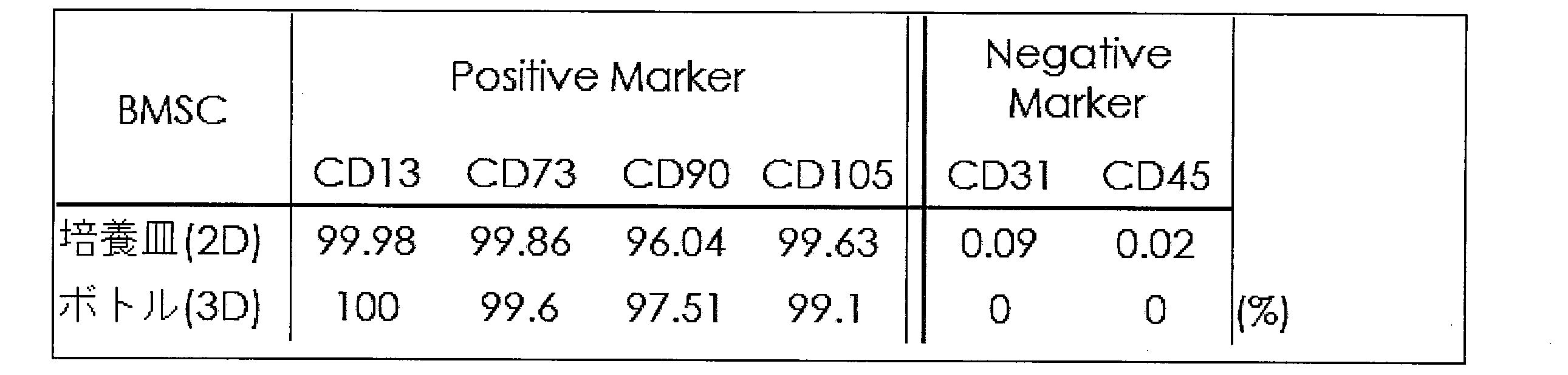
- Table 2 shows the properties of the cultured cells using the cell culture apparatus (3D culture) according to the present example and the properties of the cultured cells using the culture dish (2D culture) according to the comparative example. As shown in Table 2, the cells cultured using the cell culture apparatus according to this example had the same properties as the cells cultured on the conventional culture dish.
- Example 3 Synovial mesenchymal stem cells have a very high ability to differentiate and proliferate cartilage and are useful for regeneration of cartilage and meniscus.
- Example 3 attempts to culture synovial mesenchymal stem cells.
- the dish-like body arranged in the hollow space of the cell culture container was positioned near the lower part of the cell culture container. From the opening at the upper end of the cell culture container, the scaffold, the medium, and the cells to be cultured were put into the space of the cell culture container. The cells were 1.5 ⁇ 10 7 synovial-derived mesenchymal stem cells.
- the scaffold used 3,000 pieces of CESCO BioNOC II matrix (3D culture).
- the stroke length of the vertical movement of the annular body was 45 mm, and the moving speed in the upward or downward direction of the annular body was 1.0 mm / second.
- the cycle of the vertical movement of the annular body was 1.0 times / hour.
- the culture period was 7 days.
- FIG. 8 is a graph showing the sugar consumption (mg / dL / day) of the cells for each culture day.
- the sugar consumption of the cells was measured using a GlucCell handy glucose monitor (CESCO). As shown in FIG. 8, it was shown that the cells were appropriately cultured by using the cell culture apparatus according to this example.
- CESCO GlucCell handy glucose monitor
- FIG. 9 (A) is a photomicrograph before collection from the cell culture container on the 7th culture day
- FIG. 9 (B) is a photomicrograph after collection from the cell culture container on the 7th culture day. From FIG. 9, it can be understood that a large amount of cultured cells could be appropriately recovered by using the cell culture apparatus according to this example.
- Example 4 In order to confirm the retention and pluripotency of stem cell properties in synovial cell-derived mesenchymal stem cells after mass culture, using the synovial cell-derived mesenchymal stem cells after mass culture and recovery according to Example 3, fat cells, cartilage Differentiation into cells and bone cells was performed.
- Human Mesenchymal Stem Cell Functional Identification Kit of R & D System was used for differentiation induction. After 10 4 cells were attached to each 24-well culture plate, differentiation induction into adipocytes was performed for 14 days using a differentiation medium in which Adipogenic Supplement and ITS Supplement included in the kit were added to 50 ml of DMEM basal medium. Culture was performed.
- differentiation induction into chondrocytes culture was performed for 21 days using a differentiation medium supplemented with 50 ml of DMEM basal medium with Chondrogenic Supplement and ITS Supplement included in the kit.
- differentiation medium for induction of differentiation into bone cells, cultivation was performed for 21 days using a differentiation medium in which Osteogenic Supplement and ITS Supplement included in the kit were added to 50 ml of DMEM basal medium.
- OilRed-O, Alcian Blue, and Alizarin Red staining were performed after fixation with 4% paraformaldehyde.
- FIG. 10 is a photographic diagram showing that cells cultured in large quantities using the cell culture apparatus of the present invention can be multi-differentiated, of which (A) is a diagram showing differentiation into chondrocytes, (B ) Is a diagram showing differentiation into fat cells, and (C) is a diagram showing differentiation into bone cells. (A) is staining with Alcian Blue, (B) is staining with Oil Red O, and (C) is staining with Alizarin Red. As shown in FIG. 10, the synovial stem cells after mass culture maintained stem cell properties and pluripotency, and differentiated into adipocytes, chondrocytes, and bone cells.
Landscapes
- Health & Medical Sciences (AREA)
- Life Sciences & Earth Sciences (AREA)
- Engineering & Computer Science (AREA)
- Chemical & Material Sciences (AREA)
- Bioinformatics & Cheminformatics (AREA)
- Organic Chemistry (AREA)
- Wood Science & Technology (AREA)
- Zoology (AREA)
- Biomedical Technology (AREA)
- Biotechnology (AREA)
- Genetics & Genomics (AREA)
- General Health & Medical Sciences (AREA)
- Microbiology (AREA)
- Biochemistry (AREA)
- General Engineering & Computer Science (AREA)
- Developmental Biology & Embryology (AREA)
- Sustainable Development (AREA)
- Cell Biology (AREA)
- Rheumatology (AREA)
- Immunology (AREA)
- Medicinal Chemistry (AREA)
- Hematology (AREA)
- Virology (AREA)
- Apparatus Associated With Microorganisms And Enzymes (AREA)
- Micro-Organisms Or Cultivation Processes Thereof (AREA)
Abstract
Description
細胞培養容器の中空な空間部内に配置された皿状体を、細胞培養容器の下部近傍に位置させた。細胞培養容器の上端の開口部から、細胞培養容器の空間部へ足場、培地、及び、培養対象である細胞を入れた。細胞は5.0×10⁷個の脂肪由来間葉系幹細胞(ADSC)であった。足場はCESCO社のBioNOC IIマトリックスを5,000枚使用した(3D培養)。環状体の上下移動のストローク長さは60mm、環状体の上方向又は下方向への移動速度は1.0mm/秒とした。環状体の上下移動の周期は1.0回/時間とした。培養日数は8日であった。

実施例1では細胞はADSCであったが、実施例2では骨髄由来間葉系幹細胞(BMSC)の培養を試みる。
滑膜由来間葉系幹細胞は非常に高い軟骨分化能及び増殖能を有するため、軟骨や半月板の再生に有用である。実施例3では滑膜由来間葉系幹細胞の培養を試みる。
大量培養後の滑膜由来間葉系幹細胞における幹細胞性質の保持及び多分化能を確認するため、実施例3による大量培養及び回収後の滑膜由来間葉系幹細胞を用いて、脂肪細胞、軟骨細胞、骨細胞への分化誘導を実施した。分化誘導にはR&D System社のHuman Mesenchymal Stem Cell Functional Identification Kitを用いた。24ウエル培養プレートにそれぞれ104個の細胞を接着させた後、脂肪細胞への分化誘導には、キット付属のAdipogenic SupplementとITS SupplementをDMEM基礎培地50mlに添加した分化培地を用いて14日間の培養を行った。軟骨細胞への分化誘導には、キット付属のChondrogenic SupplementとITS SupplementをDMEM基礎培地50mlに添加した分化培地を用いて21日間の培養を行った。骨細胞への分化誘導には、キット付属のOsteogenic SupplementとITS SupplementをDMEM基礎培地50mlに添加した分化培地を用いて21日間の培養を行った。分化誘導後の脂肪細胞、軟骨細胞、骨細胞を同定するため、4%パラフォルムアルデヒド固定後にOilRed-O、Alcian Blue、Alizarin Red染色を実施した。図10は、本発明の細胞培養装置を使用して大量培養した細胞が多分化可能であることを示す写真図であり、そのうち(A)は軟骨細胞への分化を示す図であり、(B)は脂肪細胞への分化を示す図であり、(C)は骨細胞への分化を示す図である。(A)はAlcian Blueによる染色であり、(B)はOil Red Oによる染色であり、(C)はAlizarin Redによる染色である。図10の通り、大量培養後の滑膜由来間葉系幹細胞は、幹細胞性質及び多分化能を保持しており、脂肪細胞、軟骨細胞、骨細胞へと分化した。
120:底部
125:底部凸部
126:底部凹部
130:空間部
200:皿状体
220:貫通孔
230:皿凹部
210:磁着体
300:環状体
310:磁着体
320:昇降装置
700:振動装置
710:振動部
900:細胞培養装置
Claims (5)
- 下端に平坦な底部を有し、細胞を培養するための足場が充填される中空な空間部を備える略円柱体である細胞培養容器と、
磁石又は強磁性体からなる複数の磁着体を周辺部に等間隔で備え、前記細胞培養容器の中空な空間部内に前記細胞培養容器の内壁と非接触状態で水平に配置される、前記細胞培養容器の略円柱体の直径よりも微小な直径の略円盤状の皿状体と、
前記皿状体の各々の磁着体を磁力により引き付けるように、前記皿状体の各々の磁着体と対応する磁石からなる複数の磁着体を備え、前記細胞培養容器の外側に位置して環内部に前記細胞培養容器を位置させ、上方向に移動することで磁力により連動して前記皿状体を上方向に移動させて前記細胞培養容器の中空な空間部内に充填された足場を下方から押し上げ、下方向に移動することで磁力により連動して前記皿状体を下方向に移動させ、前記細胞培養容器の中空な空間部内に充填された足場を重力落下させる、上下方向に移動する略リング状の環状体と、を有することを特徴とする細胞培養装置。 - 前記皿状体の各々の磁着体は磁石であり、各々の磁石は一方の極を容器外側方向へ向けて前記皿状体に配置されており、
前記環状体の各々の磁石は前記皿状体の磁石と対応するように、他方の極を容器内側方向へ向けて前記環状体に配置されている、ことを特徴とする請求項1に記載の細胞培養装置。 - 前記細胞培養容器は、その底部の中央部に上方へ突出する内部が空間部である底部凸部を有するとともに、培養された細胞に上下方向の振動を加える振動装置の振動部がはめ込まれる前記底部凸部に対応する形状の底部凹部を前記底部の中央部に有し、
前記皿状体は、前記細胞培養容器の底部凸部がはめ込まれる皿凹部をその下面の中央部に備える、ことを特徴とする請求項1又は2に記載の細胞培養装置。 - 前記細胞培養容器内に充填される足場は、複数の細胞支持小片の集合体である、ことを特徴とする請求項1乃至3の何れか1項に記載の細胞培養装置。
- 前記培養される細胞は間葉系幹細胞である、ことを特徴とする請求項1乃至4の何れか1項に記載の細胞培養装置。
Priority Applications (5)
| Application Number | Priority Date | Filing Date | Title |
|---|---|---|---|
| JP2020500536A JP7249669B2 (ja) | 2018-02-15 | 2019-02-14 | 細胞培養装置 |
| CN201980003535.5A CN110914402B (zh) | 2018-02-15 | 2019-02-14 | 细胞培养装置 |
| US16/632,765 US11661575B2 (en) | 2018-02-15 | 2019-02-14 | Cell culture device |
| KR1020207001247A KR102355018B1 (ko) | 2018-02-15 | 2019-02-14 | 세포배양장치 |
| EP19754244.2A EP3647407B1 (en) | 2018-02-15 | 2019-02-14 | Cell culture device |
Applications Claiming Priority (2)
| Application Number | Priority Date | Filing Date | Title |
|---|---|---|---|
| JP2018024689 | 2018-02-15 | ||
| JP2018-024689 | 2018-02-15 |
Publications (1)
| Publication Number | Publication Date |
|---|---|
| WO2019160000A1 true WO2019160000A1 (ja) | 2019-08-22 |
Family
ID=67619019
Family Applications (1)
| Application Number | Title | Priority Date | Filing Date |
|---|---|---|---|
| PCT/JP2019/005203 WO2019160000A1 (ja) | 2018-02-15 | 2019-02-14 | 細胞培養装置 |
Country Status (6)
| Country | Link |
|---|---|
| US (1) | US11661575B2 (ja) |
| EP (1) | EP3647407B1 (ja) |
| JP (1) | JP7249669B2 (ja) |
| KR (1) | KR102355018B1 (ja) |
| CN (1) | CN110914402B (ja) |
| WO (1) | WO2019160000A1 (ja) |
Cited By (4)
| Publication number | Priority date | Publication date | Assignee | Title |
|---|---|---|---|---|
| JP2021122205A (ja) * | 2020-02-03 | 2021-08-30 | 株式会社フルステム | エクソソーム回収方法 |
| JP2021136932A (ja) * | 2020-03-05 | 2021-09-16 | 株式会社フルステム | 細胞培養装置 |
| WO2022259527A1 (ja) * | 2021-06-11 | 2022-12-15 | 株式会社フルステム | 細胞培養装置 |
| WO2022259525A1 (ja) * | 2021-06-11 | 2022-12-15 | 株式会社フルステム | エクソソーム回収方法 |
Families Citing this family (5)
| Publication number | Priority date | Publication date | Assignee | Title |
|---|---|---|---|---|
| WO2022115033A1 (en) * | 2020-11-24 | 2022-06-02 | Turtletree Labs Pte. Ltd. | Bioreactor systems and methods for culturing cells |
| CN112553073A (zh) * | 2020-12-11 | 2021-03-26 | 刘金桥 | 一种用于多细胞培养的复合培养罐 |
| CN112608846A (zh) * | 2021-01-15 | 2021-04-06 | 吉林大学中日联谊医院 | 用于改善卵巢早衰的干细胞外泌体的多功能细胞培养装置 |
| CN113637585A (zh) * | 2021-08-11 | 2021-11-12 | 四川大学 | 一种高效细胞培养反应器及其搅拌系统 |
| CN114480121B (zh) * | 2022-01-13 | 2022-12-09 | 山东水发生命科学研究有限公司 | 适用于细胞生长的反应装置 |
Citations (4)
| Publication number | Priority date | Publication date | Assignee | Title |
|---|---|---|---|---|
| JP2004313008A (ja) * | 2003-04-10 | 2004-11-11 | Pentax Corp | 細胞培養方法および細胞培養装置 |
| JP2006034200A (ja) * | 2004-07-28 | 2006-02-09 | Pentax Corp | 細胞培養担体、細胞培養担体の製造方法および細胞培養方法 |
| JP2007535902A (ja) * | 2003-07-17 | 2007-12-13 | グローバル セル ソリューションズ エルエルシー. | 自動細胞培養システムおよび方法 |
| JP4430317B2 (ja) | 2002-01-31 | 2010-03-10 | セスコ バイオエンジニアリング、インコーポレイテッド | 細胞培養装置 |
Family Cites Families (11)
| Publication number | Priority date | Publication date | Assignee | Title |
|---|---|---|---|---|
| JPH0677517B2 (ja) * | 1988-08-22 | 1994-10-05 | 株式会社ニッショー | 浮遊細胞培養装置 |
| US6884357B2 (en) * | 1995-02-21 | 2005-04-26 | Iqbal Waheed Siddiqi | Apparatus and method for processing magnetic particles |
| WO2000005942A1 (fr) | 1998-07-28 | 2000-02-10 | Institute Of Genetics, Chinese Academy Of Sciences | Recipient de culture et procede d'utilisation et de production de microtubercules de pommes de terre |
| JP2007203244A (ja) | 2006-02-03 | 2007-08-16 | Michio Shibatani | 破砕攪拌方法 |
| JP2009529888A (ja) * | 2006-03-14 | 2009-08-27 | ユニバーシティ オブ ロチェスター | 超薄多孔質メンブレンを有する細胞培養装置およびその使用 |
| BRPI0803630B1 (pt) | 2008-06-05 | 2018-11-06 | Fundacao Univ Federal De Sao Carlos Ufscar | biorreator de escoamento em vórtices de taylor para cultivo celular |
| US20130260364A1 (en) * | 2012-03-30 | 2013-10-03 | Yongxin Zhang | Multifunctional Bioreactor system and methods for cell sorting and culturing |
| ITFI20130220A1 (it) * | 2013-09-20 | 2015-03-21 | Azienda Ospedaliero Universitaria P Isana | Apparato e processo per la preparazione di una protesi tissutale biomimetica della membrana timpanica |
| DE102014011941B3 (de) * | 2014-08-14 | 2015-08-20 | Ika-Werke Gmbh & Co. Kg | Einlegeboden und Inkubator |
| CN104762206B (zh) * | 2015-04-22 | 2017-01-25 | 中山大学附属第一医院 | 细胞体外培养装置及培养方法 |
| CN205188309U (zh) * | 2015-10-22 | 2016-04-27 | 深圳华毓造血干细胞研究有限公司 | 贴壁性细胞的三维培养装置 |
-
2019
- 2019-02-14 CN CN201980003535.5A patent/CN110914402B/zh active Active
- 2019-02-14 EP EP19754244.2A patent/EP3647407B1/en active Active
- 2019-02-14 WO PCT/JP2019/005203 patent/WO2019160000A1/ja unknown
- 2019-02-14 JP JP2020500536A patent/JP7249669B2/ja active Active
- 2019-02-14 KR KR1020207001247A patent/KR102355018B1/ko active IP Right Grant
- 2019-02-14 US US16/632,765 patent/US11661575B2/en active Active
Patent Citations (4)
| Publication number | Priority date | Publication date | Assignee | Title |
|---|---|---|---|---|
| JP4430317B2 (ja) | 2002-01-31 | 2010-03-10 | セスコ バイオエンジニアリング、インコーポレイテッド | 細胞培養装置 |
| JP2004313008A (ja) * | 2003-04-10 | 2004-11-11 | Pentax Corp | 細胞培養方法および細胞培養装置 |
| JP2007535902A (ja) * | 2003-07-17 | 2007-12-13 | グローバル セル ソリューションズ エルエルシー. | 自動細胞培養システムおよび方法 |
| JP2006034200A (ja) * | 2004-07-28 | 2006-02-09 | Pentax Corp | 細胞培養担体、細胞培養担体の製造方法および細胞培養方法 |
Non-Patent Citations (1)
| Title |
|---|
| See also references of EP3647407A4 |
Cited By (6)
| Publication number | Priority date | Publication date | Assignee | Title |
|---|---|---|---|---|
| JP2021122205A (ja) * | 2020-02-03 | 2021-08-30 | 株式会社フルステム | エクソソーム回収方法 |
| JP2021136932A (ja) * | 2020-03-05 | 2021-09-16 | 株式会社フルステム | 細胞培養装置 |
| JP7132640B2 (ja) | 2020-03-05 | 2022-09-07 | 株式会社フルステム | 細胞培養装置 |
| WO2022259527A1 (ja) * | 2021-06-11 | 2022-12-15 | 株式会社フルステム | 細胞培養装置 |
| WO2022259525A1 (ja) * | 2021-06-11 | 2022-12-15 | 株式会社フルステム | エクソソーム回収方法 |
| US11613734B2 (en) | 2021-06-11 | 2023-03-28 | Fullstem Co., Ltd. | Method of collecting for exosome |
Also Published As
| Publication number | Publication date |
|---|---|
| KR20200018650A (ko) | 2020-02-19 |
| CN110914402A (zh) | 2020-03-24 |
| EP3647407A1 (en) | 2020-05-06 |
| US20210155887A1 (en) | 2021-05-27 |
| EP3647407B1 (en) | 2023-06-07 |
| KR102355018B1 (ko) | 2022-02-08 |
| US11661575B2 (en) | 2023-05-30 |
| JP7249669B2 (ja) | 2023-03-31 |
| EP3647407A4 (en) | 2020-08-05 |
| JPWO2019160000A1 (ja) | 2021-02-04 |
| CN110914402B (zh) | 2023-04-25 |
Similar Documents
| Publication | Publication Date | Title |
|---|---|---|
| WO2019160000A1 (ja) | 細胞培養装置 | |
| KR101678796B1 (ko) | 세포 배양 장치 및 방법 | |
| JP2021129590A (ja) | 培養方法 | |
| KR101910685B1 (ko) | 세포 수집 방법 및 시스템 | |
| US11932868B2 (en) | Microplates for magnetic 3D culture | |
| CN106222134A (zh) | 高效获取脂肪间充质干细胞的培养方法 | |
| KR102193271B1 (ko) | 3차원 다공성 지지체로부터의 배양세포 회수 방법 | |
| CN108728356A (zh) | 用于不同三维细胞团配对的装置及共培养方法 | |
| JP7132640B2 (ja) | 細胞培養装置 | |
| KR20220111250A (ko) | 현탁 세포를 위한 자동화된 배지 교환 전략 | |
| CN112522183B (zh) | 干细胞体外扩增方法 | |
| Zhang et al. | Application of bioreactor in stem cell culture | |
| EP4321605A1 (en) | Cell culture device | |
| US11299699B2 (en) | Culture container | |
| CN102174381A (zh) | 含有微球面阵列的培养皿及其运用 | |
| EP3098304A1 (en) | Hybrid cell detachment-free cell expansion system for adherent cell culturing and related proceeding protocol | |
| US20220356434A1 (en) | Magnetic cell carrier combined with a powerless bioreactor system to cell amplification kit | |
| EP3819374A1 (en) | Method for producing cell structure, carrier, and method for producing carrier | |
| CN115645439A (zh) | 细胞保存液在制备免疫抑制剂中的用途 | |
| Chin et al. | Magnetically Seeded Bioreactor for Three-Dimensional Cell Culture |
Legal Events
| Date | Code | Title | Description |
|---|---|---|---|
| 121 | Ep: the epo has been informed by wipo that ep was designated in this application |
Ref document number: 19754244 Country of ref document: EP Kind code of ref document: A1 |
|
| ENP | Entry into the national phase |
Ref document number: 2020500536 Country of ref document: JP Kind code of ref document: A |
|
| ENP | Entry into the national phase |
Ref document number: 20207001247 Country of ref document: KR Kind code of ref document: A |
|
| ENP | Entry into the national phase |
Ref document number: 2019754244 Country of ref document: EP Effective date: 20200120 |
|
| NENP | Non-entry into the national phase |
Ref country code: DE |