WO2019159754A1 - アクチュエータ装置 - Google Patents
アクチュエータ装置 Download PDFInfo
- Publication number
- WO2019159754A1 WO2019159754A1 PCT/JP2019/004019 JP2019004019W WO2019159754A1 WO 2019159754 A1 WO2019159754 A1 WO 2019159754A1 JP 2019004019 W JP2019004019 W JP 2019004019W WO 2019159754 A1 WO2019159754 A1 WO 2019159754A1
- Authority
- WO
- WIPO (PCT)
- Prior art keywords
- actuator
- actuator member
- support member
- energy
- actuator device
- Prior art date
- Legal status (The legal status is an assumption and is not a legal conclusion. Google has not performed a legal analysis and makes no representation as to the accuracy of the status listed.)
- Ceased
Links
Images






Classifications
-
- F—MECHANICAL ENGINEERING; LIGHTING; HEATING; WEAPONS; BLASTING
- F03—MACHINES OR ENGINES FOR LIQUIDS; WIND, SPRING, OR WEIGHT MOTORS; PRODUCING MECHANICAL POWER OR A REACTIVE PROPULSIVE THRUST, NOT OTHERWISE PROVIDED FOR
- F03G—SPRING, WEIGHT, INERTIA OR LIKE MOTORS; MECHANICAL-POWER PRODUCING DEVICES OR MECHANISMS, NOT OTHERWISE PROVIDED FOR OR USING ENERGY SOURCES NOT OTHERWISE PROVIDED FOR
- F03G7/00—Mechanical-power-producing mechanisms, not otherwise provided for or using energy sources not otherwise provided for
- F03G7/06—Mechanical-power-producing mechanisms, not otherwise provided for or using energy sources not otherwise provided for using expansion or contraction of bodies due to heating, cooling, moistening, drying or the like
- F03G7/061—Mechanical-power-producing mechanisms, not otherwise provided for or using energy sources not otherwise provided for using expansion or contraction of bodies due to heating, cooling, moistening, drying or the like characterised by the actuating element
- F03G7/0614—Mechanical-power-producing mechanisms, not otherwise provided for or using energy sources not otherwise provided for using expansion or contraction of bodies due to heating, cooling, moistening, drying or the like characterised by the actuating element using shape memory elements
- F03G7/06143—Wires
-
- F—MECHANICAL ENGINEERING; LIGHTING; HEATING; WEAPONS; BLASTING
- F03—MACHINES OR ENGINES FOR LIQUIDS; WIND, SPRING, OR WEIGHT MOTORS; PRODUCING MECHANICAL POWER OR A REACTIVE PROPULSIVE THRUST, NOT OTHERWISE PROVIDED FOR
- F03G—SPRING, WEIGHT, INERTIA OR LIKE MOTORS; MECHANICAL-POWER PRODUCING DEVICES OR MECHANISMS, NOT OTHERWISE PROVIDED FOR OR USING ENERGY SOURCES NOT OTHERWISE PROVIDED FOR
- F03G7/00—Mechanical-power-producing mechanisms, not otherwise provided for or using energy sources not otherwise provided for
- F03G7/06—Mechanical-power-producing mechanisms, not otherwise provided for or using energy sources not otherwise provided for using expansion or contraction of bodies due to heating, cooling, moistening, drying or the like
- F03G7/061—Mechanical-power-producing mechanisms, not otherwise provided for or using energy sources not otherwise provided for using expansion or contraction of bodies due to heating, cooling, moistening, drying or the like characterised by the actuating element
- F03G7/06114—Mechanical-power-producing mechanisms, not otherwise provided for or using energy sources not otherwise provided for using expansion or contraction of bodies due to heating, cooling, moistening, drying or the like characterised by the actuating element using the thermal expansion or contraction of solid materials
-
- F—MECHANICAL ENGINEERING; LIGHTING; HEATING; WEAPONS; BLASTING
- F03—MACHINES OR ENGINES FOR LIQUIDS; WIND, SPRING, OR WEIGHT MOTORS; PRODUCING MECHANICAL POWER OR A REACTIVE PROPULSIVE THRUST, NOT OTHERWISE PROVIDED FOR
- F03G—SPRING, WEIGHT, INERTIA OR LIKE MOTORS; MECHANICAL-POWER PRODUCING DEVICES OR MECHANISMS, NOT OTHERWISE PROVIDED FOR OR USING ENERGY SOURCES NOT OTHERWISE PROVIDED FOR
- F03G7/00—Mechanical-power-producing mechanisms, not otherwise provided for or using energy sources not otherwise provided for
- F03G7/06—Mechanical-power-producing mechanisms, not otherwise provided for or using energy sources not otherwise provided for using expansion or contraction of bodies due to heating, cooling, moistening, drying or the like
- F03G7/062—Mechanical-power-producing mechanisms, not otherwise provided for or using energy sources not otherwise provided for using expansion or contraction of bodies due to heating, cooling, moistening, drying or the like characterised by the activation arrangement
-
- F—MECHANICAL ENGINEERING; LIGHTING; HEATING; WEAPONS; BLASTING
- F03—MACHINES OR ENGINES FOR LIQUIDS; WIND, SPRING, OR WEIGHT MOTORS; PRODUCING MECHANICAL POWER OR A REACTIVE PROPULSIVE THRUST, NOT OTHERWISE PROVIDED FOR
- F03G—SPRING, WEIGHT, INERTIA OR LIKE MOTORS; MECHANICAL-POWER PRODUCING DEVICES OR MECHANISMS, NOT OTHERWISE PROVIDED FOR OR USING ENERGY SOURCES NOT OTHERWISE PROVIDED FOR
- F03G7/00—Mechanical-power-producing mechanisms, not otherwise provided for or using energy sources not otherwise provided for
- F03G7/06—Mechanical-power-producing mechanisms, not otherwise provided for or using energy sources not otherwise provided for using expansion or contraction of bodies due to heating, cooling, moistening, drying or the like
- F03G7/063—Mechanical-power-producing mechanisms, not otherwise provided for or using energy sources not otherwise provided for using expansion or contraction of bodies due to heating, cooling, moistening, drying or the like characterised by the mechanic interaction
- F03G7/06324—Mechanical-power-producing mechanisms, not otherwise provided for or using energy sources not otherwise provided for using expansion or contraction of bodies due to heating, cooling, moistening, drying or the like characterised by the mechanic interaction increasing or decreasing in volume
-
- F—MECHANICAL ENGINEERING; LIGHTING; HEATING; WEAPONS; BLASTING
- F03—MACHINES OR ENGINES FOR LIQUIDS; WIND, SPRING, OR WEIGHT MOTORS; PRODUCING MECHANICAL POWER OR A REACTIVE PROPULSIVE THRUST, NOT OTHERWISE PROVIDED FOR
- F03G—SPRING, WEIGHT, INERTIA OR LIKE MOTORS; MECHANICAL-POWER PRODUCING DEVICES OR MECHANISMS, NOT OTHERWISE PROVIDED FOR OR USING ENERGY SOURCES NOT OTHERWISE PROVIDED FOR
- F03G7/00—Mechanical-power-producing mechanisms, not otherwise provided for or using energy sources not otherwise provided for
- F03G7/06—Mechanical-power-producing mechanisms, not otherwise provided for or using energy sources not otherwise provided for using expansion or contraction of bodies due to heating, cooling, moistening, drying or the like
- F03G7/066—Actuator control or monitoring
-
- H—ELECTRICITY
- H02—GENERATION; CONVERSION OR DISTRIBUTION OF ELECTRIC POWER
- H02N—ELECTRIC MACHINES NOT OTHERWISE PROVIDED FOR
- H02N10/00—Electric motors using thermal effects
-
- H—ELECTRICITY
- H02—GENERATION; CONVERSION OR DISTRIBUTION OF ELECTRIC POWER
- H02N—ELECTRIC MACHINES NOT OTHERWISE PROVIDED FOR
- H02N11/00—Generators or motors not provided for elsewhere; Alleged perpetua mobilia obtained by electric or magnetic means
Definitions
- the present disclosure relates to an actuator device using an actuator member that deforms based on changes in electrical, photonic, chemical, thermal, and other energy states.
- an actuator member described in Patent Document 1 is known as this type of actuator member.
- the actuator member described in Patent Document 1 has a structure in which a single polymer fiber is pre-twisted or a structure in which a plurality of polymer fibers are pre-twisted, and has a characteristic of being deformed by a temperature change based on electric heating or white heating. doing.
- the actuator member described in Patent Document 1 When the actuator member described in Patent Document 1 is once heated and then naturally cooled, the actuator member is deformed in a direction opposite to the deformation direction during heating. That is, the actuator member is deformed based on a change in the state of thermal energy. If torque can be applied to an arbitrary operated part using the deformation of the actuator member, the operated part can be rotationally displaced.
- An object of the present disclosure is to provide an actuator device that can apply torque to an actuated portion by using an actuator member that deforms based on a change in energy state.
- the actuator device includes an actuator member, a support member, an actuated portion, and an energy adjustment portion.
- the actuator member is formed in a fiber shape and is deformed in a direction along the central axis based on a change in energy state.
- the support member is formed in a rod shape around a predetermined axis.
- the actuated portion is supported by the support member so as to be rotatable in a circumferential direction around a predetermined axis.
- the energy adjusting unit adjusts the energy state of the actuator member.
- the actuator member is spirally wound around the support member, and is deformed in a direction along the central axis to apply a circumferential torque centered on a predetermined axis to the operated portion.
- the actuator member when the energy state of the actuator member is changed by adjusting the energy state of the actuator member by the energy adjusting unit, the actuator member is deformed in the direction along the central axis. At this time, since the actuator member is spirally wound around the support member, the entire actuator member is deformed in a spiral direction around a predetermined axis. By utilizing the deformation of the actuator member in the spiral direction, a torque in the circumferential direction around a predetermined axis can be applied to the operated part.
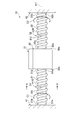
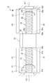
- FIG. 1 is a diagram schematically showing the structure of the actuator device according to the first embodiment.
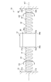
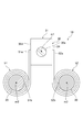
- FIG. 2 is a cross-sectional view showing a cross-sectional structure taken along line II-II in FIG.
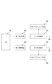
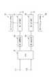
- FIG. 3 is a block diagram illustrating an electrical configuration of the actuator device according to the first embodiment.
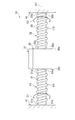
- FIG. 4 is a diagram schematically illustrating the structure of a first modification of the actuator device according to the first embodiment.
- FIG. 5 is a diagram schematically illustrating the structure of a second modification of the actuator device according to the first embodiment.
- FIG. 6 is a block diagram illustrating an electrical configuration of the actuator device according to the second embodiment.
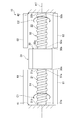
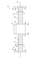
- FIG. 7 is a diagram schematically showing the structure of the actuator device according to the third embodiment.
- FIG. 1 is a diagram schematically showing the structure of the actuator device according to the first embodiment.
- FIG. 2 is a cross-sectional view showing a cross-sectional structure taken along line II-II in FIG.
- FIG. 3 is a block diagram illustrating
- FIG. 8 is a cross-sectional view showing a cross-sectional structure taken along line VIII-VIII in FIG.
- FIG. 9 is a diagram schematically showing the structure of the actuator device of the fourth embodiment.
- FIG. 10 is a diagram schematically illustrating the structure of an actuator device according to a first modification of the fourth embodiment.
- FIG. 11 is a diagram schematically illustrating the structure of an actuator device according to a second modification of the fourth embodiment.
- FIG. 12 is a diagram schematically illustrating the structure of the actuator device according to the fifth embodiment.
- FIG. 13 is a block diagram illustrating an electrical configuration of the actuator device according to the fifth embodiment.
- FIG. 14 is a diagram schematically illustrating the structure of an actuator device according to another embodiment.
- FIG. 15 is a diagram schematically illustrating the structure of an actuator device according to another embodiment.
- FIG. 16 is a diagram schematically illustrating the structure of an actuator device according to another embodiment.
- the actuator device 10 of this embodiment includes support members 21 and 22, an actuated portion 30, holding members 41 and 42, and actuator members 51 and 52.
- Support members 21 and 22 are rod-shaped members formed in a columnar shape around a predetermined axis m1.
- the support members 21 and 22 are made of an elastic material. Elastomer is adopted as the material of the support members 21 and 22 of the present embodiment. In addition, as a material of the support members 21 and 22, nylon, rubber, or the like can be adopted.
- the one end portion 21a of the first support member 21 is fixed to one side surface 30a of the operated portion 30 formed in a cubic shape or a rectangular parallelepiped shape.
- the other end 21b of the first support member 21 is fixed to a first holding member 41 assembled to a housing or the like (not shown).
- One end portion 22 a of the second support member 22 is fixed to the other side surface 30 b of the operated portion 30.
- the other side surface 30 b is a side surface opposite to the one side surface 30 a to which the one end portion 21 a of the first support member 21 is fixed in the operated portion 30.
- the other end 22b of the second support member 22 is fixed to a second holding member 42 assembled to a housing or the like (not shown).
- the support members 21 and 22 support the operated part 30.
- the actuated portion 30 can be rotated by elastically twisting and deforming the support members 21 and 22 in the circumferential direction about the axis m1. That is, the support members 21 and 22 support the actuated portion 30 so as to be rotatable in the circumferential direction about the axis m1.
- a sensor device 31 is fixedly provided on the operated part 30.
- the sensor device 31 is a device that detects a predetermined physical quantity such as an infrared sensor.
- the first actuator member 51 is made of a fibrous elongated member that is spirally wound around the outer peripheral surface of the first support member 21.
- the 1st actuator member 51 consists of a non-twisted member which is not twisted in the peripheral direction centering on the central axis m10.
- One end 51 a of the first actuator member 51 is fixed to the outer peripheral surface of the one end 21 a of the first support member 21.
- the other end 51 b of the first actuator member 51 is fixed to the outer peripheral surface of the other end 21 b of the first support member 21.
- an intermediate portion from one end 51 a to the other end 51 b may be fixed to the outer peripheral surface of the first support member 21.
- the second actuator member 52 is formed of an elongated fiber member that is spirally wound around the outer peripheral surface of the second support member 22.
- the second actuator member 52 is also composed of a non-twisted member that is not twisted in the circumferential direction around the central axis m20.
- One end 52 a of the second actuator member 52 is fixed to the outer peripheral surface of the one end 22 a of the second support member 22.
- the other end 52 b of the second actuator member 52 is fixed to the outer peripheral surface of the other end 22 b of the second support member 22.
- the second actuator member 52 may also be fixed to the first support member 21 at an intermediate portion from one end 52a to the other end 52b.
- the actuator members 51 and 52 are made of a material that deforms in the direction along the central axes m10 and m20 based on the change in the energy state. Specifically, the actuator members 51 and 52 are formed of polymer fibers such as polyamide that are deformed based on a change in the state of thermal energy.
- the first actuator member 51 When the first actuator member 51 is heated to transition from the low temperature state to the high temperature state, the first actuator member 51 contracts in the direction along the central axis m10, that is, in the spiral direction, as compared with the case of the low temperature state. Due to the contraction deformation in the spiral direction of the first actuator member 51, the torque in the circumferential direction C1 about the axis m1 is applied to the first support member 21 to which the first actuator member 51 is fixed. The member 21 is elastically twisted and deformed in the circumferential direction C1. Thereby, since the torque in the circumferential direction C1 is applied to the operated portion 30 fixed to the one end portion 21a of the first support member 21, the operated portion 30 and the sensor device 31 are separated from the reference position shown in FIG.
- the second actuator member 52 is elastically torsionally deformed in the circumferential direction C1 following the actuated portion 30 to allow rotation of the actuated portion 30 in the circumferential direction C1.
- the actuated part 30 and the sensor device 31 rotate to a first set position P1 indicated by a two-dot chain line that is shifted from the reference position P0 indicated by a solid line in FIG. 2 by a predetermined angle ⁇ 1 in the circumferential direction C1. .
- the first actuator member 51 transitions from the high temperature state to the low temperature state due to natural cooling or the like, the first actuator member 51 expands in the direction along the central axis m10 and returns to the original state. That is, since the torque applied to the first support member 21 from the first actuator member 51 is lost, the first support member 21 is elastically deformed and returns to the original state. Thereby, the actuated part 30 and the sensor device 31 are returned to the reference position P0.
- the second actuator member 52 transitions from the low temperature state to the high temperature state, the second actuator member 52 contracts in the spiral direction along the central axis m20. Due to the contraction deformation of the second actuator member 52 in the spiral direction, the second support member 22 to which the second actuator member 52 is fixed is given a torque in the circumferential direction C2 centered on the axis m1, so that the second The support member 22 is elastically twisted and deformed in the circumferential direction C2.
- the circumferential direction C ⁇ b> 2 is a direction opposite to the direction of torque applied from the first actuator member 51 to the first support member 21.
- the second support member 22 Since the second support member 22 is torsionally deformed in the circumferential direction C2, torque in the circumferential direction C2 is applied to the operated part 30 fixed to the one end 22a of the second support member 22, and thus the operated part 30 and The sensor device 31 rotates in the circumferential direction C2 from the reference position shown in FIG. As a result, the actuated part 30 and the sensor device 31 rotate to a second set position P2 indicated by a two-dot chain line that is shifted from the reference position P0 indicated by a solid line in FIG. 2 by a predetermined angle ⁇ 2 in the circumferential direction C2. . Further, when the second actuator member 52 expands due to the transition of the second actuator member 52 from the high temperature state to the low temperature state due to natural cooling or the like, the second support member 22 returns to the original state. The sensor device 31 returns to the reference position P0.
- the actuator device 10 includes a first heating device 61, a second heating device 62, and an ECU (Electronic Control Unit) 70.
- ECU Electronic Control Unit
- the heating devices 61 and 62 are devices for heating the actuator members 51 and 52, respectively.
- the heating devices 61 and 62 include, for example, coils arranged so as to cover the periphery of the actuator members 51 and 52, respectively, and heat the actuator members 51 and 52 by generating heat based on energization of the coils.
- the heating devices 61 and 62 correspond to an energy adjusting unit that adjusts the state of thermal energy of the actuator members 51 and 52.
- the ECU 70 is mainly configured by a microcomputer having a CPU, a ROM, a RAM, and the like.
- the ECU 70 executes position control for changing the position of the sensor device 31 by executing a program stored in advance in the ROM and driving the heating devices 61 and 62. Specifically, when changing the position of the sensor device 31 in the circumferential direction C1, the ECU 70 transmits a control signal to the first heating device 61 to drive the first heating device 61, thereby driving the first actuator member. 51 is heated. At this time, the ECU 70 controls the heating amount of the first actuator member 51 by including the instruction value of the heating amount of the first actuator member 51 in the control signal.
- the ECU 70 naturally cools the first actuator member 51 by stopping the first heating device 61 when returning the sensor device 31 to the reference position P0.
- the ECU 70 displaces the sensor device 31 to an arbitrary position within the range from the reference position P0 to the first set position P1 shown in FIG. 2 through such thermal energy control of the first actuator member 51.
- the ECU 70 performs the same thermal energy control on the second actuator member 52 through the second heating device 62, thereby moving the sensor device 31 from the reference position P0 to the second set position P2 shown in FIG. Displace to any position in the range.
- the actuator device 10 of the present embodiment described above the operations and effects shown in the following (1) and (2) can be obtained.
- the actuator members 51 and 52 When the state of thermal energy of the actuator members 51 and 52 is changed by the heating devices 61 and 62 and the actuator members 51 and 52 are deformed in the direction along the central axes m10 and m20, the actuator members 51 and 52 as a whole are axes. Deforms in a spiral direction around m1.
- the support members 21 and 22 are elastically torsionally deformed in the circumferential directions C1 and C2 by the force applied to the support members 21 and 22 based on the deformation of the actuator members 51 and 52, so that the operated part 30 is in the circumferential directions C1 and C2. Rotate to. That is, by using the deformation of the actuator members 51 and 52 in the spiral direction, the torque in the circumferential directions C1 and C2 can be applied to the operated part 30.
- the orientation angles ⁇ 1 and ⁇ 2 of the actuator members 51 and 52 are acute angles formed by the center axes m10 and m20 of the actuator member with respect to the center axis m1 of the spiral, and are equal to the so-called spiral angle. Since the actuator member described in Patent Document 1 has a structure in which polymer fibers are twisted in advance, if the actuator member is further deformed in a spiral shape so as to increase the orientation angle, the actuator member may be damaged.
- the actuator member described in Patent Document 1 since the actuator members 51 and 52 of the present embodiment are made of a non-twisted member that is not twisted in the circumferential direction around the central axes m10 and m20, the orientation angles ⁇ 1 and ⁇ 2 of the actuator members 51 and 52 are as follows. Can be increased. Therefore, the torque applied to the actuated part 30 can be increased. If the orientation angles ⁇ 1 and ⁇ 2 can be increased, the amount of torque generated by the actuator members 51 and 52 per unit length in the direction along the central axis m1 can be increased. Therefore, since the overall length of the actuator device 10 in the direction along the central axis m1 can be shortened, it is possible to reduce the dead space that needs to be secured when the actuator device 10 is mounted on the subassembly.
- the torque in the circumferential direction C2 can be applied to the operated part 30 by heating the actuator member 52 by the heating device 62.
- the torque of the circumferential direction C1 can be provided to the to-be-actuated part 30 by stopping the heating apparatus 62 and cooling the actuator member 52 naturally. Therefore, an action and effect similar to the actuator device 10 of the first embodiment can be obtained.
- the first support member 21 and the second support member 22 are made of a conductive elastic material capable of generating heat when energized.
- a conductive elastomer can be used as the conductive elastic material.
- the actuator device 10 includes a first energization device 63 for energizing the first support member 21 and a second energization device 64 for energizing the second support member 22. .
- the first support member 21 When the first support member 21 is energized by the first energization device 63, the first support member 21 generates heat.
- the first actuator member 51 contracts and deforms, and torque in the circumferential direction C ⁇ b> 1 is applied to the actuated unit 30 and the sensor device 31. .
- the second support member 22 when the second support member 22 is energized by the second energization device 64, the second support member 22 generates heat. When the heat of the second support member 22 is transmitted to the second actuator member 52, the second actuator member 52 contracts and deforms, and torque in the circumferential direction C2 is applied to the operated portion 30 and the sensor device 31. .
- the energization devices 63 and 64 correspond to an energy adjustment unit that indirectly adjusts the state of thermal energy of the actuator members 51 and 52 by supplying electric energy to the support members 21 and 22.
- the ECU 70 controls the energization amount of the first actuator member 51 by transmitting a control signal including an instruction value of the energization amount of the first support member 21 to the first energization device 63.
- the ECU 70 controls the energization amount of the second actuator member 52 by transmitting a control signal including an instruction value of the energization amount of the second support member 22 to the second energization device 64.
- the ECU 70 displaces the sensor device 31 to any position within the range from the first setting position P1 to the second setting position P2 shown in FIG. 2 through such energization control.
- the operation and effect shown in the following (3) can be further obtained.
- (3) The state of the thermal energy of the actuator members 51 and 52 is indirectly adjusted by the electric energy applied to the support members 21 and 22 from the energization devices 63 and 64.
- the state of the thermal energy of the actuator members 51, 52 changes and the actuator members 51, 52 are deformed in the direction along the central axes m10, m20, the entire actuator members 51, 52 are deformed in a spiral direction centered on the axis m1. To do.
- the support members 21 and 22 are elastically torsionally deformed in the circumferential directions C1 and C2 by the force applied to the support members 21 and 22 based on the deformation of the actuator members 51 and 52, so that the operated part 30 is in the circumferential directions C1 and C2. Rotate to. That is, by using the deformation of the actuator members 51 and 52 in the spiral direction, the torque in the circumferential directions C1 and C2 can be applied to the operated part 30.
- the actuator device 10 of this embodiment includes a support member 24 instead of the support members 21 and 22 of the first embodiment.
- the support member 24 is formed in a columnar shape around the axis m1.
- the actuated portion 30 is formed with an insertion hole 30 c that penetrates from one side surface 30 a to the other side surface 30 b.
- the support member 24 is inserted through the insertion hole 30c.
- Bearings 32 and 33 are provided between the inner peripheral surface of the operated part 30 and the outer peripheral surface of the support member 24. By these bearings 32 and 33, the actuated portion 30 is supported so as to be rotatable in the circumferential directions C 1 and C 2 with respect to the support member 24.
- the support member 24 is formed of a material capable of reducing the frictional force generated between the actuator members 51 and 52. Metal is adopted as the material of the support members 21 and 22 of the present embodiment. As a result, the actuator members 51 and 52 can be contracted and stretched while sliding on the outer peripheral surfaces of the support members 21 and 22.
- one end 51 a of the first actuator member 51 is fixed to one side 30 a of the actuated portion 30.
- the other end 21 b of the first actuator member 51 is fixed to the first holding member 41.
- one end portion 52 a of the second actuator member 52 is fixed to the other side surface 30 b of the operated portion 30.
- the other end 52 b of the second actuator member 52 is fixed to the second holding member 42.
- the holding members 41 and 42 correspond to members different from the operated part 30.
- the circumferential direction is provided on the one side surface 30 a of the actuated portion 30. C1 torque is directly applied. Due to this torque, the actuated part 30 and the sensor device 31 rotate in the circumferential direction C1. Further, when the heating of the first actuator member 51 by the first heating device 61 is stopped and the first actuator member 51 is cooled by natural cooling or the like, the first actuator member 51 expands in the spiral direction. The unit 30 and the sensor device 31 return to the reference position P0.
- the second actuator member 52 contracts in the spiral direction by the second actuator member 52 being heated by the second heating device 62
- the torque in the circumferential direction C2 is directly applied to the other side surface 30b of the operated part 30. To be granted. Due to this torque, the actuated part 30 and the sensor device 31 rotate in the circumferential direction C2. Further, when the heating of the second actuator member 52 by the second heating device 62 is stopped and the first actuator member 51 is cooled by natural cooling or the like, the second actuator member 52 expands in the spiral direction.
- the unit 30 and the sensor device 31 return to the reference position P0.
- the operation and effect shown in the following (4) can be obtained.
- the state of the thermal energy of the actuator members 51 and 52 is changed by the heating devices 61 and 62 and the actuator members 51 and 52 are deformed in the direction along the central axes m10 and m20, the actuator members 51 and 52 as a whole are axes. Deforms in a spiral direction around m1. Based on the deformation of the actuator members 51 and 52, the operated part 30 rotates in the circumferential directions C1 and C2.
- the torque in the circumferential directions C1 and C2 can be applied to the operated part 30. Further, torque can be directly applied from the actuator members 51 and 52 to the operated part 30. Therefore, compared with the case where the torque is indirectly applied from the actuator members 51 and 52 to the actuated portion 30 via the support members 21 and 22 as in the actuator device 10 of the first embodiment, a larger torque is actuated. It can be given to the part.
- a fourth embodiment of the actuator device 10 will be described.
- the description will focus on the differences from the actuator device 10 of the first embodiment.
- the first actuator member 51 is heated by the heat generated from the first support member 21 as in the actuator device 10 of the second embodiment, the first actuator member 51 is contracted and deformed by heating.
- the inner peripheral surface of the actuator member 51 is pressed against the outer peripheral surface of the first support member 21.
- the contact area between the first actuator member 51 and the first support member 21 increases, and as a result, the heat transfer area of the first actuator member 51 relative to the first support member 21 increases.
- the contraction deformation of the first actuator member 51 may be promoted. This is a factor that lowers the control accuracy of the deformation amount of the first actuator member 51, and thus the control accuracy of the rotational position of the actuated portion 30 may be deteriorated. Such a problem may occur in the second actuator member 52 as well.
- the actuator device 10 of the present embodiment by adopting a configuration in which the actuator members 51 and 52 are heated from the outer peripheral portion, the inner peripheral portions of the actuator members 51 and 52 are hardly pressed against the support members 21 and 22. I have to.
- the first heating device 61 that heats the first actuator member 51 from the outer peripheral side
- the second actuator member 52 that heats the second actuator member 52 from the outer peripheral side.
- the second heating device 62 is provided. The first heating device 61 and the second heating device 62 are controlled by the ECU 70 as shown in FIG.
- the first heating device 61 heats the outer peripheral portion of the first actuator member 51. According to such a configuration, the temperature of the outer peripheral portion of the first actuator member 51 heated by the first heating device 61 is likely to rise. On the other hand, since the inner peripheral portion of the first actuator member 51 is in contact with the first support member 21, the heat of the inner peripheral portion of the first actuator member 51 is radiated to the first support member 21. As a result, the temperature of the first actuator member 51 becomes higher than the temperature of the first support member 21 when the first actuator member 51 is deformed.
- the amount of contraction deformation of the inner peripheral part becomes smaller than the amount of contraction deformation of the outer peripheral part. Therefore, since the inner peripheral surface of the first actuator member 51 is hardly pressed against the outer peripheral surface of the first support member 21, an increase in the heat transfer area of the first actuator member 51 relative to the first support member 21 can be suppressed. . That is, since the amount of heat input from the first support member 21 to the first actuator member 51 is unlikely to change, the deformation amount of the first actuator member 51 can be accurately controlled. Similar actions and effects can be obtained with respect to the second actuator member 52.
- the heat radiation of the first support member 21 can be promoted by the heat radiating fins 101.
- the amount of contraction deformation of the inner peripheral portion of the first actuator member 51 can be further reduced.
- the amount of heat input from the first support member 21 to the first actuator member 51 is less likely to change, so that the deformation amount of the first actuator member 51 can be controlled with higher accuracy.
- the other end 21 b of the first support member 21 is in contact with the first cooling part 121 provided on the first holding member 41.
- the first cooling unit 121 cools the first holding member 41.
- the Peltier device which cools the 1st holding member 41 by energization, for example, and the cooling water circulation mechanism which cools the 1st holding member 41 with the cooling water which flows through the inside can be used.
- the other end 22 b of the second support member 22 is in contact with the second cooling part 122 provided on the second holding member 42.
- the heat dissipation of the first support member 21 can be further promoted, and as a result, the amount of contraction deformation of the inner peripheral portion of the first actuator member 51 can be further reduced. Accordingly, the amount of heat input from the first support member 21 to the first actuator member 51 is less likely to change, so that the deformation amount of the first actuator member 51 can be controlled with higher accuracy.
- the actuator device 10 of the present embodiment includes a first temperature sensor 111 provided on the first actuator member 51 and a second temperature sensor 112 provided on the second actuator member 52. .
- the first temperature sensor 111 detects the temperature of the first actuator member 51 and outputs a signal corresponding to the detected temperature.
- the second temperature sensor 112 detects the temperature of the second actuator member 52 and outputs a signal corresponding to the detected temperature.
- the first temperature sensor 111 and the second temperature sensor 112 correspond to a temperature detection unit.
- the output signals of the first temperature sensor 111 and the second temperature sensor 112 are taken into the ECU 70.
- the ECU 70 acquires information on the temperature of the first actuator member 51 based on the output signal of the first temperature sensor 111, and from the first energization device 63 to the first support member based on the acquired temperature of the first actuator member 51.
- the amount of energization to 21, specifically, the magnitude of the voltage applied to the first support member 21 is controlled. For example, this energization control is performed as follows.
- the torsional deformation amount of the first support member 21 has a correlation with the contraction deformation amount of the first actuator member 51, that is, the temperature of the first actuator member 51. Therefore, the rotation angle ⁇ ⁇ b> 1 of the sensor device 31 has a correlation with the temperature of the first actuator member 51.
- these relationships are obtained in advance through experiments or the like, and based on the experimental results, the target rotation angle ⁇ * of the sensor device 31 and the target temperature T * of the first actuator member 51 A first map showing the above relationship is created in advance, and the first map is stored in the storage device of the ECU 70.
- the temperature of the first actuator member 51 has a correlation with the amount of power supplied from the first power supply device 63 to the first support member 21.
- these relationships are obtained in advance through experiments or the like, and based on the experimental results, the target temperature T * of the first actuator member 51 and the energization amount instruction value of the first energization device 63.
- a second map indicating the relationship with P * is created in advance, and the second map is stored in the storage device of the ECU 70.
- the ECU 70 sets the energization amount instruction value P * of the first energization device 63 according to the target rotation angle ⁇ * of the sensor device 31 based on the first map and the second map. That is, the ECU 70 sets the target temperature T * of the first actuator member 51 from the target rotation angle ⁇ * of the sensor device 31 based on the first map. Further, the ECU 70 sets the energization amount instruction value P * of the first energization device 63 based on the second map from the target temperature T * of the first actuator member 51.
- the ECU 70 calculates a difference value ⁇ (T * ⁇ T) between the temperature T of the first actuator member 51 acquired by the first temperature sensor 111 and the target temperature T *, and the difference value ⁇ (T * ⁇ T).
- the energization amount correction value ⁇ P according to T) is calculated by an arithmetic expression or the like.
- the energization amount correction value ⁇ P is set so as to have a positive correlation with the difference value ⁇ (T * ⁇ T).
- the ECU 70 controls the energization amount from the first energization device 63 to the first support member 21 using a value “P * + ⁇ P” obtained by correcting the energization amount instruction value P * by the energization amount correction value ⁇ P.
- the ECU 70 acquires information on the temperature of the second actuator member 52 based on the output signal of the second temperature sensor 112, and outputs the information from the second energization device 64 based on the acquired temperature of the second actuator member 52.
- the amount of current supplied to the support member 22 is controlled. According to the actuator device 10 of the present embodiment described above, the operation and effect shown in the following (6) can be further obtained.
- the first actuator member 51 When the first actuator member 51 is heated by the heat generated from the first support member 21, the first actuator member 51 contracts and the inner peripheral surface of the first actuator member 51 becomes the first support member 21. When pressed, the heat transfer area of the first actuator member 51 with respect to the first support member 21 increases, so that the temperature of the first actuator member 51 easily rises as described above. In addition, as described above, this becomes a factor that reduces the control accuracy of the deformation amount of the first actuator member 51. In this regard, according to the actuator device 10 of the present embodiment, the temperature of the first actuator member 51 has risen above the target temperature T * by increasing the heat transfer area of the first actuator member 51 with respect to the first support member 21.
- the energization amount from the second energization device 64 to the second support member 22 is corrected so that the temperature increase is canceled out.
- the temperature of the first actuator member 51 can be accurately controlled to the target temperature T *, so that the deformation amount of the first actuator member 51 can be accurately controlled. Similar actions and effects can be obtained with respect to the second actuator member 52.
- each embodiment can also be implemented with the following forms.
- the first actuator member 51 contracts, the first support member 21 is torsionally deformed by a frictional force that acts between the first actuator member 51 and the first support member 21. If possible, the first actuator member 51 may not be fixed to the first support member 21. Similarly, the second actuator member 52 may not be fixed to the second support member 22.
- a heat diffusion layer 24 c for increasing the heat transfer efficiency of the actuator members 51 and 52 may be provided on the outer peripheral surface of the support member 24 of the third embodiment.
- a thermal diffusion layer may be provided on each outer peripheral surface of the support members 21 and 22 of the first embodiment and the second embodiment.
- a gap may be formed between the support member 24 and the first actuator member 51 and between the support member 24 and the second actuator member 52.
- the actuator members 51 and 52 may be disposed inside the support member 24. Specifically, as shown in FIG. 15, a spiral hole 24d into which the first actuator member 51 is inserted and a spiral hole 24e into which the second actuator member 52 is inserted inside the support member 24. And may be formed.
- the actuator members 51 and 52 are not limited to a spiral structure, and may have a spiral structure.
- the first actuator member 51 is spirally disposed on the outer periphery of the first support member 25, and the second actuator member 52 is spirally disposed on the outer periphery of the second support member 26.
- the first support member 25 is formed in a cylindrical shape around an axis m2 parallel to the axis m1.
- the first support member 25 is formed in a columnar shape around an axis m3 parallel to the axis m1.
- One end portion 51 a of the first actuator member 51 is fixed to one side surface 30 d of the operated portion, and the other end portion 51 b of the first actuator member 51 is fixed to the first support member 25.
- one end portion 52 a of the second actuator member 52 is fixed to one side surface 30 e of the operated portion, and the other end portion 52 b of the second actuator member 52 is fixed to the second support member 26. Even with such a configuration, the actuated portion 30 can be rotated about the axis m ⁇ b> 1 by contraction deformation of the first actuator member 51 and the second actuator member 52.
- the material of the actuator members 51 and 52 is not limited to the polymer fiber, and an appropriate material that deforms based on changes in electrical, optical, chemical, thermal, and other energy states may be used. it can. Examples of such materials include shape memory alloys, dielectric elastomers, magnetic gels, and conductive polymers.
- an appropriate energy adjustment unit other than the heating devices 61 and 62 and the energization devices 63 and 64 may be used according to the material of the actuator members 51 and 52.
Landscapes
- Engineering & Computer Science (AREA)
- Chemical & Material Sciences (AREA)
- Combustion & Propulsion (AREA)
- Mechanical Engineering (AREA)
- General Engineering & Computer Science (AREA)
- Micromachines (AREA)
Abstract
アクチュエータ装置(10)は、アクチュエータ部材(51,52)と、支持部材(21,22)と、エネルギ調整部と、を備える。アクチュエータ部材は、繊維状に細長く形成され、エネルギ状態の変化に基づき中心軸に沿った方向に変形する。支持部材は、所定の軸線を中心に棒状に形成される。エネルギ調整部は、アクチュエータ部材のエネルギ状態を調整する。アクチュエータ部材は、支持部材に螺旋状に巻かれるとともに、中心軸に沿った方向に変形することにより所定の軸線を中心とする周方向のトルクを被作動部に付与する。
Description
本出願は、2018年2月19日に出願された日本国特許出願2018-027074号と、2018年7月2日に出願された日本国特許出願2018-126336号と、に基づくものであって、その優先権の利益を主張するものであり、その特許出願の全ての内容が、参照により本明細書に組み込まれる。
本開示は、電気的、光子的、化学的、熱的、及びその他のエネルギ的な状態の変化に基づいて変形するアクチュエータ部材を用いたアクチュエータ装置に関する。
従来、この種のアクチュエータ部材としては、特許文献1に記載のアクチュエータ部材が知られている。特許文献1に記載のアクチュエータ部材は、単数のポリマ繊維を予め撚った構造、あるいは複数のポリマ繊維を予め撚り合わせた構造からなり、電気加熱や白色加熱に基づく温度変化により変形する特性を有している。
特許文献1に記載のアクチュエータ部材を一旦加熱した後に自然冷却させた場合、このアクチュエータ部材は加熱時の変形方向とは逆方向に変形する。すなわち、アクチュエータ部材は、その熱エネルギの状態の変化に基づき変形する。このアクチュエータ部材の変形を利用して任意の被作動部にトルクを付与することができれば、被作動部を回転変位させることが可能である。
本開示の目的は、エネルギ状態の変化に基づき変形するアクチュエータ部材を利用することにより被作動部にトルクを付与することの可能なアクチュエータ装置を提供することにある。
本開示の一態様によるアクチュエータ装置は、アクチュエータ部材と、支持部材と、被作動部と、エネルギ調整部と、を備える。アクチュエータ部材は、繊維状に細長く形成され、エネルギ状態の変化に基づき中心軸に沿った方向に変形する。支持部材は、所定の軸線を中心に棒状に形成される。被作動部は、支持部材により所定の軸線を中心とする周方向に回転可能に支持される。エネルギ調整部は、アクチュエータ部材のエネルギ状態を調整する。アクチュエータ部材は、支持部材に螺旋状に巻かれるとともに、中心軸に沿った方向に変形することにより所定の軸線を中心とする周方向のトルクを被作動部に付与する。
この構成によれば、エネルギ調整部によってアクチュエータ部材のエネルギ状態が調整されることでアクチュエータ部材のエネルギ状態が変化すると、アクチュエータ部材が中心軸に沿った方向に変形する。このとき、アクチュエータ部材が支持部材に螺旋状に巻き付けられているため、アクチュエータ部材全体としては所定の軸線を中心とする螺旋方向に変形することになる。このアクチュエータ部材の螺旋方向の変形を利用することにより、所定の軸線を中心とする周方向のトルクを被作動部に付与することができる。
以下、アクチュエータ装置の一実施形態について図面を参照しながら説明する。説明の理解を容易にするため、各図面において同一の構成要素に対しては可能な限り同一の符号を付して、重複する説明は省略する。
<第1実施形態>
はじめに、アクチュエータ装置の第1実施形態について説明する。図1に示されるように、本実施形態のアクチュエータ装置10は、支持部材21,22と、被作動部30と、保持部材41,42と、アクチュエータ部材51,52とを備えている。
<第1実施形態>
はじめに、アクチュエータ装置の第1実施形態について説明する。図1に示されるように、本実施形態のアクチュエータ装置10は、支持部材21,22と、被作動部30と、保持部材41,42と、アクチュエータ部材51,52とを備えている。
支持部材21,22は、所定の軸線m1を中心に円柱状に形成された棒状の部材からなる。支持部材21,22は弾性体材料からなる。本実施形態の支持部材21,22の材質としては、エラストマが採用されている。なお、支持部材21,22の材質としては、ナイロンやゴム等を採用することも可能である。
第1支持部材21の一端部21aは、立方体状又は直方体状に形成された被作動部30の一側面30aに固定されている。第1支持部材21の他端部21bは、図示しない筐体等に組み付けられた第1保持部材41に固定されている。第2支持部材22の一端部22aは、被作動部30の他側面30bに固定されている。他側面30bは、被作動部30において第1支持部材21の一端部21aが固定される一側面30aとは反対側の側面である。第2支持部材22の他端部22bは、図示しない筐体等に組み付けられた第2保持部材42に固定されている。支持部材21,22は、被作動部30を支持している。また、軸線m1を中心とする周方向に支持部材21,22が弾性的に捩り変形することにより被作動部30を回転させることができる。すなわち、支持部材21,22は、被作動部30を、軸線m1を中心とする周方向に回転可能に支持している。
被作動部30には、センサ装置31が固定して設けられている。センサ装置31は、赤外線センサ等の所定の物理量を検出する装置である。
第1アクチュエータ部材51は、第1支持部材21の外周面に螺旋状に巻き付けられる繊維状の細長い部材からなる。第1アクチュエータ部材51は、その中心軸m10を中心とする周方向に撚られていない無撚状の部材からなる。第1アクチュエータ部材51の一端部51aは、第1支持部材21の一端部21aの外周面に固定されている。第1アクチュエータ部材51の他端部51bは、第1支持部材21の他端部21bの外周面に固定されている。なお、第1アクチュエータ部材51に関しては、その一端部51aから他端部51bまでの中間部分が第1支持部材21の外周面に固定されていてもよい。
第1アクチュエータ部材51は、第1支持部材21の外周面に螺旋状に巻き付けられる繊維状の細長い部材からなる。第1アクチュエータ部材51は、その中心軸m10を中心とする周方向に撚られていない無撚状の部材からなる。第1アクチュエータ部材51の一端部51aは、第1支持部材21の一端部21aの外周面に固定されている。第1アクチュエータ部材51の他端部51bは、第1支持部材21の他端部21bの外周面に固定されている。なお、第1アクチュエータ部材51に関しては、その一端部51aから他端部51bまでの中間部分が第1支持部材21の外周面に固定されていてもよい。
第2アクチュエータ部材52は、第2支持部材22の外周面に螺旋状に巻き付けられる細長い繊維状の部材からなる。第2アクチュエータ部材52も、その中心軸m20を中心とする周方向に撚られていない無撚状の部材からなる。第2アクチュエータ部材52の一端部52aは、第2支持部材22の一端部22aの外周面に固定されている。第2アクチュエータ部材52の他端部52bは、第2支持部材22の他端部22bの外周面に固定されている。なお、第2アクチュエータ部材52に関しても、その一端部52aから他端部52bまでの中間部分が第1支持部材21に固定されていてもよい。
アクチュエータ部材51,52は、エネルギ状態の変化に基づき中心軸m10,m20に沿った方向に変形する材料により形成されている。具体的には、アクチュエータ部材51,52は、その熱エネルギの状態の変化に基づいて変形するポリアミド等のポリマ繊維により形成されている。
第1アクチュエータ部材51は、加熱されることにより低温状態から高温状態に遷移すると、低温状態である場合と比較して、その中心軸m10に沿った方向、すなわち螺旋方向に収縮する。この第1アクチュエータ部材51の螺旋方向の収縮変形により、第1アクチュエータ部材51が固定された第1支持部材21には軸線m1を中心とする周方向C1のトルクが付与されるため、第1支持部材21が周方向C1に弾性的に捩り変形する。これにより、第1支持部材21の一端部21aに固定された被作動部30に周方向C1のトルクが付与されるため、被作動部30及びセンサ装置31は、図1に示される基準位置から周方向C1に回転する。なお、この際、第2アクチュエータ部材52が被作動部30に追従して周方向C1に弾性的に捩り変形することにより、被作動部30の周方向C1の回転が許容される。結果的に、被作動部30及びセンサ装置31は、図2に実線で示される基準位置P0から周方向C1に所定角度θ1だけずれた、二点鎖線で示される第1設定位置P1まで回転する。
また、自然冷却等により第1アクチュエータ部材51が高温状態から低温状態に遷移すると、第1アクチュエータ部材51は、その中心軸m10に沿った方向に伸張して元の状態に戻る。すなわち、第1アクチュエータ部材51から第1支持部材21に付与されているトルクがなくなるため、第1支持部材21が弾性変形して元の状態に戻る。これにより、被作動部30及びセンサ装置31は基準位置P0に復帰する。
同様に、第2アクチュエータ部材52も、低温状態から高温状態に遷移すると、その中心軸m20に沿った螺旋方向に収縮する。この第2アクチュエータ部材52の螺旋方向の収縮変形により、第2アクチュエータ部材52が固定された第2支持部材22には、軸線m1を中心とする周方向C2のトルクが付与されるため、第2支持部材22が周方向C2に弾性的に捩り変形する。周方向C2は、第1アクチュエータ部材51から第1支持部材21に付与されるトルクの方向とは反対の方向である。第2支持部材22が周方向C2に捩り変形することにより、第2支持部材22の一端部22aに固定された被作動部30に周方向C2のトルクが付与されるため、被作動部30及びセンサ装置31は、図1に示される基準位置から周方向C2に回転する。結果的に、被作動部30及びセンサ装置31は、図2に実線で示される基準位置P0から周方向C2に所定角度θ2だけずれた、二点鎖線で示される第2設定位置P2まで回転する。また、自然冷却等により第2アクチュエータ部材52が高温状態から低温状態に遷移することにより、第2アクチュエータ部材52が伸張すると、第2支持部材22が元の状態に戻るため、被作動部30及びセンサ装置31は基準位置P0に復帰する。
次に、アクチュエータ装置10の電気的な構成について説明する。
図3に示されるように、アクチュエータ装置10は、第1加熱装置61と、第2加熱装置62と、ECU(Electronic Control Unit)70とを備えている。
図3に示されるように、アクチュエータ装置10は、第1加熱装置61と、第2加熱装置62と、ECU(Electronic Control Unit)70とを備えている。
加熱装置61,62は、アクチュエータ部材51,52をそれぞれ加熱するための装置である。加熱装置61,62は、例えばアクチュエータ部材51,52のそれぞれの周囲を覆うように配置されるコイルを備えており、コイルの通電に基づき発熱することによりアクチュエータ部材51,52をそれぞれ加熱する。本実施形態では、加熱装置61,62が、アクチュエータ部材51,52の熱エネルギの状態を調整するエネルギ調整部に相当する。
ECU70は、CPUやROM、RAM等を有するマイクロコンピュータを中心に構成されている。ECU70は、ROMに予め記憶されたプログラムを実行して加熱装置61,62を駆動させることにより、センサ装置31の位置を変化させる位置制御を実行する。
具体的には、ECU70は、センサ装置31の位置を周方向C1に変化させる場合には、制御信号を第1加熱装置61に送信して第1加熱装置61を駆動させることにより第1アクチュエータ部材51を加熱する。この際、ECU70は、第1アクチュエータ部材51の加熱量の指示値を制御信号に含めることにより、第1アクチュエータ部材51の加熱量を制御する。また、ECU70は、センサ装置31を基準位置P0に戻す場合には、第1加熱装置61を停止させることにより第1アクチュエータ部材51を自然冷却させる。ECU70は、このような第1アクチュエータ部材51の熱エネルギ制御を通じて、センサ装置31を、図2に示される基準位置P0から第1設定位置P1までの範囲の任意の位置に変位させる。
具体的には、ECU70は、センサ装置31の位置を周方向C1に変化させる場合には、制御信号を第1加熱装置61に送信して第1加熱装置61を駆動させることにより第1アクチュエータ部材51を加熱する。この際、ECU70は、第1アクチュエータ部材51の加熱量の指示値を制御信号に含めることにより、第1アクチュエータ部材51の加熱量を制御する。また、ECU70は、センサ装置31を基準位置P0に戻す場合には、第1加熱装置61を停止させることにより第1アクチュエータ部材51を自然冷却させる。ECU70は、このような第1アクチュエータ部材51の熱エネルギ制御を通じて、センサ装置31を、図2に示される基準位置P0から第1設定位置P1までの範囲の任意の位置に変位させる。
また、ECU70は、第2加熱装置62を通じて第2アクチュエータ部材52に対して同様の熱エネルギ制御を行うことにより、センサ装置31を、図2に示される基準位置P0から第2設定位置P2までの範囲の任意の位置に変位させる。
以上説明した本実施形態のアクチュエータ装置10によれば、以下の(1)及び(2)に示される作用及び効果を得ることができる。
以上説明した本実施形態のアクチュエータ装置10によれば、以下の(1)及び(2)に示される作用及び効果を得ることができる。
(1)加熱装置61,62によりアクチュエータ部材51,52の熱エネルギの状態が変化してアクチュエータ部材51,52が中心軸m10,m20に沿った方向に変形すると、アクチュエータ部材51,52全体が軸線m1を中心とする螺旋方向に変形する。このアクチュエータ部材51,52の変形に基づき支持部材21,22に加わる力によって支持部材21,22が周方向C1,C2に弾性的に捩り変形することで、被作動部30が周方向C1,C2に回転する。すなわち、アクチュエータ部材51,52の螺旋方向の変形を利用することにより、周方向C1,C2のトルクを被作動部30に付与することができる。
(2)より大きなトルクを被作動部30に付与するためには、図1に示される螺旋の中心軸m1に対するアクチュエータ部材51,52の配向角度φ1,φ2を大きくする必要がある。配向角度φ1,φ2は、図1に示されるように、螺旋の中心軸m1に対してアクチュエータ部材の中心軸m10,m20がなす鋭角の角度であって、いわゆる螺旋角度に等しい。特許文献1に記載のアクチュエータ部材は、予めポリマ繊維を撚った構造からなるため、配向角度が大きくなるようにアクチュエータ部材を螺旋状に更に変形させると、アクチュエータ部材の損傷を招くおそれがある。すなわち、特許文献1に記載のアクチュエータ部材は強度の観点から配向角度を大きくすることが難しく、結果として被作動部に十分なトルクを付与することが困難である。この点、本実施形態のアクチュエータ部材51,52は、中心軸m10,m20を中心とする周方向に撚られていない無撚状の部材からなるため、アクチュエータ部材51,52の配向角度φ1,φ2を大きくすることができる。よって、被作動部30に付与されるトルクを大きくすることができる。また、配向角度φ1,φ2を大きくすることができれば、中心軸m1に沿った方向における単位長さ当たりのアクチュエータ部材51,52のトルク発生量を大きくすることができる。よって、中心軸m1に沿った方向におけるアクチュエータ装置10の全長を短くすることができるため、アクチュエータ装置10をサブアッセンブリに搭載する際に確保する必要のあるデットスペースを縮小することが可能である。
(第1変形例)
次に、第1実施形態のアクチュエータ装置10の第1変形例について説明する。
図4に示されるように、本変形例の被作動部30の一側面30aには、第1支持部材21及び第1アクチュエータ部材51に代えて、金属等からなる軸部材23の一端部23aが固定されている。軸部材23の他端部23bは、第1保持部材41に設けられた軸受け80により回転可能に支持されている。したがって、本変形例のアクチュエータ装置10では、被作動部30の一側面30bに固定された支持部材22にのみアクチュエータ部材52が巻き付けられている。
次に、第1実施形態のアクチュエータ装置10の第1変形例について説明する。
図4に示されるように、本変形例の被作動部30の一側面30aには、第1支持部材21及び第1アクチュエータ部材51に代えて、金属等からなる軸部材23の一端部23aが固定されている。軸部材23の他端部23bは、第1保持部材41に設けられた軸受け80により回転可能に支持されている。したがって、本変形例のアクチュエータ装置10では、被作動部30の一側面30bに固定された支持部材22にのみアクチュエータ部材52が巻き付けられている。
本変形例のアクチュエータ装置10によれば、加熱装置62によりアクチュエータ部材52を加熱することにより被作動部30に周方向C2のトルクを付与することができる。また、加熱装置62を停止させてアクチュエータ部材52を自然冷却させることにより被作動部30に周方向C1のトルクを付与することができる。よって、第1実施形態のアクチュエータ装置10に類似の作用及び効果を得ることができる。
(第2変形例)
次に、第1実施形態のアクチュエータ装置10の第2変形例について説明する。
図5に示されるように、本変形例のアクチュエータ装置10では、第1支持部材21に対する第1アクチュエータ部材51の巻き付け方向が第1実施形態の巻き付け方向と逆方向になっている。したがって、第1加熱装置61により第1アクチュエータ部材51が加熱されて第1アクチュエータ部材51が収縮変形すると、被作動部30及びセンサ装置31には周方向C2のトルクが付与される。すなわち、本変形例のアクチュエータ装置10では、第1アクチュエータ部材51の収縮変形により被作動部30及びセンサ装置31に加わるトルクの方向と、第2アクチュエータ部材52の収縮変形により被作動部30及びセンサ装置31に加わるトルクの方向とが同一の方向となっている。
次に、第1実施形態のアクチュエータ装置10の第2変形例について説明する。
図5に示されるように、本変形例のアクチュエータ装置10では、第1支持部材21に対する第1アクチュエータ部材51の巻き付け方向が第1実施形態の巻き付け方向と逆方向になっている。したがって、第1加熱装置61により第1アクチュエータ部材51が加熱されて第1アクチュエータ部材51が収縮変形すると、被作動部30及びセンサ装置31には周方向C2のトルクが付与される。すなわち、本変形例のアクチュエータ装置10では、第1アクチュエータ部材51の収縮変形により被作動部30及びセンサ装置31に加わるトルクの方向と、第2アクチュエータ部材52の収縮変形により被作動部30及びセンサ装置31に加わるトルクの方向とが同一の方向となっている。
このような構成によれば、第1アクチュエータ部材51及び第2アクチュエータ部材52のいずれか一方が何らかの理由により損傷した場合でも、損傷の無い他方のアクチュエータ部材を用いて被作動部30及びセンサ装置31にトルクを付与することができる。すなわち、被作動部30及びセンサ装置31を変位させる手段の冗長設計が可能となる。
<第2実施形態>
次に、アクチュエータ装置10の第2実施形態について説明する。以下、第1実施形態のアクチュエータ装置10との相違点を中心に説明する。
本実施形態のアクチュエータ装置10では、第1支持部材21及び第2支持部材22が、通電により発熱することの可能な導電性の弾性体材料からなる。導電性の弾性体材料としては、例えば導電性エラストマを用いることができる。
次に、アクチュエータ装置10の第2実施形態について説明する。以下、第1実施形態のアクチュエータ装置10との相違点を中心に説明する。
本実施形態のアクチュエータ装置10では、第1支持部材21及び第2支持部材22が、通電により発熱することの可能な導電性の弾性体材料からなる。導電性の弾性体材料としては、例えば導電性エラストマを用いることができる。
図6に示されるように、アクチュエータ装置10は、第1支持部材21を通電するための第1通電装置63と、第2支持部材22を通電するための第2通電装置64とを備えている。第1通電装置63により第1支持部材21が通電されると、第1支持部材21が発熱する。この第1支持部材21の熱が第1アクチュエータ部材51に伝達されることにより、第1アクチュエータ部材51が収縮変形して、被作動部30及びセンサ装置31に周方向C1のトルクが付与される。
同様に、第2通電装置64により第2支持部材22が通電されると、第2支持部材22が発熱する。この第2支持部材22の熱が第2アクチュエータ部材52に伝達されることにより、第2アクチュエータ部材52が収縮変形して、被作動部30及びセンサ装置31に周方向C2のトルクが付与される。
このように、本実施形態では、通電装置63,64が、支持部材21,22に電気エネルギを供給することによりアクチュエータ部材51,52の熱エネルギの状態を間接的に調整するエネルギ調整部に相当する。
ECU70は、第1支持部材21の通電量の指示値を含む制御信号を第1通電装置63に送信することにより、第1アクチュエータ部材51の通電量を制御する。同様に、ECU70は、第2支持部材22の通電量の指示値を含む制御信号を第2通電装置64に送信することにより、第2アクチュエータ部材52の通電量を制御する。ECU70は、このような通電制御を通じて、センサ装置31を、図2に示される第1設定位置P1から第2設定位置P2までの範囲の任意の位置に変位させる。
ECU70は、第1支持部材21の通電量の指示値を含む制御信号を第1通電装置63に送信することにより、第1アクチュエータ部材51の通電量を制御する。同様に、ECU70は、第2支持部材22の通電量の指示値を含む制御信号を第2通電装置64に送信することにより、第2アクチュエータ部材52の通電量を制御する。ECU70は、このような通電制御を通じて、センサ装置31を、図2に示される第1設定位置P1から第2設定位置P2までの範囲の任意の位置に変位させる。
以上説明した本実施形態のアクチュエータ装置10によれば、上記の(2)に示される作用及び効果に加え、以下の(3)に示される作用及び効果を更に得ることができる。
(3)通電装置63,64から支持部材21,22に付与される電気エネルギにより、アクチュエータ部材51,52の熱エネルギの状態が間接的に調整される。アクチュエータ部材51,52の熱エネルギの状態が変化してアクチュエータ部材51,52が中心軸m10,m20に沿った方向に変形すると、アクチュエータ部材51,52全体が軸線m1を中心とする螺旋方向に変形する。このアクチュエータ部材51,52の変形に基づき支持部材21,22に加わる力によって支持部材21,22が周方向C1,C2に弾性的に捩り変形することで、被作動部30が周方向C1,C2に回転する。すなわち、アクチュエータ部材51,52の螺旋方向の変形を利用することにより、周方向C1,C2のトルクを被作動部30に付与することができる。
(3)通電装置63,64から支持部材21,22に付与される電気エネルギにより、アクチュエータ部材51,52の熱エネルギの状態が間接的に調整される。アクチュエータ部材51,52の熱エネルギの状態が変化してアクチュエータ部材51,52が中心軸m10,m20に沿った方向に変形すると、アクチュエータ部材51,52全体が軸線m1を中心とする螺旋方向に変形する。このアクチュエータ部材51,52の変形に基づき支持部材21,22に加わる力によって支持部材21,22が周方向C1,C2に弾性的に捩り変形することで、被作動部30が周方向C1,C2に回転する。すなわち、アクチュエータ部材51,52の螺旋方向の変形を利用することにより、周方向C1,C2のトルクを被作動部30に付与することができる。
<第3実施形態>
次に、アクチュエータ装置10の第3実施形態について説明する。以下、第1実施形態のアクチュエータ装置10との相違点を中心に説明する。
図7に示されるように、本実施形態のアクチュエータ装置10は、第1実施形態の支持部材21,22に代えて、支持部材24を備えている。支持部材24は、軸線m1を中心に円柱状に形成されている。図8に示されるように、被作動部30には、その一側面30aから他側面30bに貫通する挿通孔30cが形成されている。挿通孔30cには、支持部材24が挿通されている。被作動部30の内周面と支持部材24の外周面との間には、軸受け32,33が設けられている。これらの軸受け32,33により、被作動部30は、支持部材24に対して周方向C1,C2に回転可能に支持されている。
次に、アクチュエータ装置10の第3実施形態について説明する。以下、第1実施形態のアクチュエータ装置10との相違点を中心に説明する。
図7に示されるように、本実施形態のアクチュエータ装置10は、第1実施形態の支持部材21,22に代えて、支持部材24を備えている。支持部材24は、軸線m1を中心に円柱状に形成されている。図8に示されるように、被作動部30には、その一側面30aから他側面30bに貫通する挿通孔30cが形成されている。挿通孔30cには、支持部材24が挿通されている。被作動部30の内周面と支持部材24の外周面との間には、軸受け32,33が設けられている。これらの軸受け32,33により、被作動部30は、支持部材24に対して周方向C1,C2に回転可能に支持されている。
支持部材24は、アクチュエータ部材51,52との間に発生する摩擦力を小さくすることの可能な材料により形成されている。本実施形態の支持部材21,22の材質としては、金属が採用されている。これにより、アクチュエータ部材51,52は、支持部材21,22の外周面を滑りながら収縮変形及び伸張変形することが可能である。
図7に示されるように、第1アクチュエータ部材51の一端部51aは、被作動部30の一側面30aに固定されている。また、第1アクチュエータ部材51の他端部21bは、第1保持部材41に固定されている。同様に、第2アクチュエータ部材52の一端部52aは、被作動部30の他側面30bに固定されている。また、第2アクチュエータ部材52の他端部52bは、第2保持部材42に固定されている。本実施形態では、保持部材41,42が、被作動部30とは異なる部材に相当する。
本実施形態のアクチュエータ装置10では、第1加熱装置61によって第1アクチュエータ部材51が加熱されることで第1アクチュエータ部材51が螺旋方向に収縮すると、被作動部30の一側面30aには周方向C1のトルクが直接的に付与される。このトルクにより、被作動部30及びセンサ装置31が周方向C1に回転する。また、第1加熱装置61による第1アクチュエータ部材51の加熱が停止して、自然冷却等により第1アクチュエータ部材51が冷却されると、第1アクチュエータ部材51が螺旋方向に伸張するため、被作動部30及びセンサ装置31が基準位置P0に復帰する。
同様に、第2加熱装置62によって第2アクチュエータ部材52が加熱されることで第2アクチュエータ部材52が螺旋方向に収縮すると、被作動部30の他側面30bには周方向C2のトルクが直接的に付与される。このトルクにより、被作動部30及びセンサ装置31が周方向C2に回転する。また、第2加熱装置62による第2アクチュエータ部材52の加熱が停止して、自然冷却等により第1アクチュエータ部材51が冷却されると、第2アクチュエータ部材52が螺旋方向に伸張するため、被作動部30及びセンサ装置31が基準位置P0に復帰する。
以上説明した本実施形態のアクチュエータ装置10によれば、上記の(2)に示される作用及び効果に加え、以下の(4)に示される作用及び効果を得ることができる。
(4)加熱装置61,62によりアクチュエータ部材51,52の熱エネルギの状態が変化してアクチュエータ部材51,52が中心軸m10,m20に沿った方向に変形すると、アクチュエータ部材51,52全体が軸線m1を中心とする螺旋方向に変形する。このアクチュエータ部材51,52の変形に基づき、被作動部30が周方向C1,C2に回転する。すなわち、アクチュエータ部材51,52の螺旋方向の変形を利用することにより、周方向C1,C2のトルクを被作動部30に付与することができる。また、アクチュエータ部材51,52から被作動部30にトルクを直接的に付与することができる。そのため、第1実施形態のアクチュエータ装置10のようにアクチュエータ部材51,52から支持部材21,22を介して被作動部30にトルクを間接的に付与する場合と比較すると、より大きなトルクを被作動部に付与することが可能となる。
(4)加熱装置61,62によりアクチュエータ部材51,52の熱エネルギの状態が変化してアクチュエータ部材51,52が中心軸m10,m20に沿った方向に変形すると、アクチュエータ部材51,52全体が軸線m1を中心とする螺旋方向に変形する。このアクチュエータ部材51,52の変形に基づき、被作動部30が周方向C1,C2に回転する。すなわち、アクチュエータ部材51,52の螺旋方向の変形を利用することにより、周方向C1,C2のトルクを被作動部30に付与することができる。また、アクチュエータ部材51,52から被作動部30にトルクを直接的に付与することができる。そのため、第1実施形態のアクチュエータ装置10のようにアクチュエータ部材51,52から支持部材21,22を介して被作動部30にトルクを間接的に付与する場合と比較すると、より大きなトルクを被作動部に付与することが可能となる。
<第4実施形態>
次に、アクチュエータ装置10の第4実施形態について説明する。以下、第1実施形態のアクチュエータ装置10との相違点を中心に説明する。
第2実施形態のアクチュエータ装置10のように、第1支持部材21から発せられる熱により第1アクチュエータ部材51を加熱するような構成の場合、加熱により第1アクチュエータ部材51が収縮変形すると、第1アクチュエータ部材51の内周面が第1支持部材21の外周面に押し付けられることになる。これにより、第1アクチュエータ部材51と第1支持部材21との接触面積が増加するため、結果的に第1支持部材21に対する第1アクチュエータ部材51の伝熱面積が増加することになる。よって、第1支持部材21に対する第1アクチュエータ部材51の入熱量が増加するため、第1アクチュエータ部材51の収縮変形が促進される可能性がある。これは、第1アクチュエータ部材51の変形量の制御精度を低下させる要因となるため、被作動部30の回転位置の制御精度が悪化するおそれがある。このような課題は、第2アクチュエータ部材52にも同様に生じ得る。
次に、アクチュエータ装置10の第4実施形態について説明する。以下、第1実施形態のアクチュエータ装置10との相違点を中心に説明する。
第2実施形態のアクチュエータ装置10のように、第1支持部材21から発せられる熱により第1アクチュエータ部材51を加熱するような構成の場合、加熱により第1アクチュエータ部材51が収縮変形すると、第1アクチュエータ部材51の内周面が第1支持部材21の外周面に押し付けられることになる。これにより、第1アクチュエータ部材51と第1支持部材21との接触面積が増加するため、結果的に第1支持部材21に対する第1アクチュエータ部材51の伝熱面積が増加することになる。よって、第1支持部材21に対する第1アクチュエータ部材51の入熱量が増加するため、第1アクチュエータ部材51の収縮変形が促進される可能性がある。これは、第1アクチュエータ部材51の変形量の制御精度を低下させる要因となるため、被作動部30の回転位置の制御精度が悪化するおそれがある。このような課題は、第2アクチュエータ部材52にも同様に生じ得る。
そこで、本実施形態のアクチュエータ装置10では、アクチュエータ部材51,52を外周部分から加熱する構成を採用することにより、アクチュエータ部材51,52の内周部分が支持部材21,22に押し付けられ難くなるようにしている。
具体的には、図9に示されるように、本実施形態のアクチュエータ装置10では、第1アクチュエータ部材51を外周側から加熱する第1加熱装置61、及び第2アクチュエータ部材52を外周側から加熱する第2加熱装置62を備えている。第1加熱装置61及び第2加熱装置62は、図3に示されるようにECU70により制御される。
具体的には、図9に示されるように、本実施形態のアクチュエータ装置10では、第1アクチュエータ部材51を外周側から加熱する第1加熱装置61、及び第2アクチュエータ部材52を外周側から加熱する第2加熱装置62を備えている。第1加熱装置61及び第2加熱装置62は、図3に示されるようにECU70により制御される。
以上説明した本実施形態のアクチュエータ装置10によれば、以下の(5)に示される作用及び効果を更に得ることができる。
(5)第1加熱装置61は、第1アクチュエータ部材51の外周部分を加熱する。このような構成によれば、第1加熱装置61により加熱される第1アクチュエータ部材51の外周部分は温度上昇し易くなる。これに対し、第1アクチュエータ部材51の内周部分は第1支持部材21に接触しているため、第1アクチュエータ部材51の内周部分の熱は第1支持部材21に放熱される。結果的に、第1アクチュエータ部材51の変形時に、第1アクチュエータ部材51の温度が第1支持部材21の温度よりも高くなる。これにより、第1アクチュエータ部材51では、その外周部分の収縮変形量よりも、その内周部分の収縮変形量の方が小さくなる。よって、第1アクチュエータ部材51の内周面が第1支持部材21の外周面に押し付けられ難くなるため、第1支持部材21に対する第1アクチュエータ部材51の伝熱面積の増加を抑制することができる。すなわち、第1支持部材21から第1アクチュエータ部材51への入熱量が変化し難くなるため、第1アクチュエータ部材51の変形量を精度良く制御することが可能となる。第2アクチュエータ部材52に関しても同様の作用及び効果を得ることができる。
(5)第1加熱装置61は、第1アクチュエータ部材51の外周部分を加熱する。このような構成によれば、第1加熱装置61により加熱される第1アクチュエータ部材51の外周部分は温度上昇し易くなる。これに対し、第1アクチュエータ部材51の内周部分は第1支持部材21に接触しているため、第1アクチュエータ部材51の内周部分の熱は第1支持部材21に放熱される。結果的に、第1アクチュエータ部材51の変形時に、第1アクチュエータ部材51の温度が第1支持部材21の温度よりも高くなる。これにより、第1アクチュエータ部材51では、その外周部分の収縮変形量よりも、その内周部分の収縮変形量の方が小さくなる。よって、第1アクチュエータ部材51の内周面が第1支持部材21の外周面に押し付けられ難くなるため、第1支持部材21に対する第1アクチュエータ部材51の伝熱面積の増加を抑制することができる。すなわち、第1支持部材21から第1アクチュエータ部材51への入熱量が変化し難くなるため、第1アクチュエータ部材51の変形量を精度良く制御することが可能となる。第2アクチュエータ部材52に関しても同様の作用及び効果を得ることができる。
(第1変形例)
次に、第4実施形態のアクチュエータ装置10の第1変形例について説明する。
図10に示されるように、本変形例のアクチュエータ装置10では、第1支持部材21の他端部21bの外周部分に複数の放熱フィン101が形成されている。また、第2支持部材22の他端部22bの外周部分にも複数の放熱フィン102が形成されている。
次に、第4実施形態のアクチュエータ装置10の第1変形例について説明する。
図10に示されるように、本変形例のアクチュエータ装置10では、第1支持部材21の他端部21bの外周部分に複数の放熱フィン101が形成されている。また、第2支持部材22の他端部22bの外周部分にも複数の放熱フィン102が形成されている。
このような構成によれば、放熱フィン101により第1支持部材21の放熱を促進させることができるため、結果的に第1アクチュエータ部材51の内周部分の収縮変形量を更に小さくすることができる。これにより、第1支持部材21から第1アクチュエータ部材51への入熱量が更に変化し難くなるため、第1アクチュエータ部材51の変形量を更に精度良く制御することが可能となる。
また、放熱フィン102により第2支持部材22の放熱を促進させることができるため、第2アクチュエータ部材52に関しても同様の作用及び効果を得ることができる。
(第2変形例)
次に、第4実施形態のアクチュエータ装置10の第2変形例について説明する。
(第2変形例)
次に、第4実施形態のアクチュエータ装置10の第2変形例について説明する。
図11に示されるように、本変形例のアクチュエータ装置10では、第1支持部材21の他端部21bが、第1保持部材41に設けられた第1冷却部121に接触している。第1冷却部121は、第1保持部材41を冷却する。第1冷却部121としては、例えば通電により第1保持部材41を冷却するペルチェ素子や、内部を流れる冷却水により第1保持部材41を冷却する冷却水循環機構を用いることができる。また、第2支持部材22の他端部22bは、同様に、第2保持部材42に設けられた第2冷却部122に接触している。
このような構成によれば、第1支持部材21の放熱を更に促進させることができるため、結果的に第1アクチュエータ部材51の内周部分の収縮変形量を更に小さくすることができる。これにより、第1支持部材21から第1アクチュエータ部材51への入熱量が更に変化し難くなるため、第1アクチュエータ部材51の変形量を更に精度良く制御することが可能となる。
また、第2冷却部122により第2支持部材22の放熱を促進させることができるため、第2アクチュエータ部材52に関しても同様の作用及び効果を得ることができる。
<第5実施形態>
次に、アクチュエータ装置10の第5実施形態について説明する。以下、第2実施形態のアクチュエータ装置10との相違点を中心に説明する。
<第5実施形態>
次に、アクチュエータ装置10の第5実施形態について説明する。以下、第2実施形態のアクチュエータ装置10との相違点を中心に説明する。
図12に示されるように、本実施形態のアクチュエータ装置10は、第1アクチュエータ部材51に設けられる第1温度センサ111と、第2アクチュエータ部材52に設けられる第2温度センサ112とを備えている。第1温度センサ111は、第1アクチュエータ部材51の温度を検出するとともに、検出した温度に応じた信号を出力する。第2温度センサ112は、第2アクチュエータ部材52の温度を検出するとともに、検出した温度に応じた信号を出力する。本実施形態では、第1温度センサ111及び第2温度センサ112が温度検出部に相当する。
図13に示されるように、第1温度センサ111及び第2温度センサ112のそれぞれの出力信号は、ECU70に取り込まれている。ECU70は、第1温度センサ111の出力信号に基づいて第1アクチュエータ部材51の温度の情報を取得するとともに、取得した第1アクチュエータ部材51の温度に基づいて第1通電装置63から第1支持部材21への通電量、具体的には第1支持部材21に印加されている電圧の大きさを制御する。例えば、この通電制御は次のように行われる。
図2に示されるセンサ装置31の回転角度θ1は、第1支持部材21の捩り変形量と相関関係がある。また、第1支持部材21の捩り変形量は、第1アクチュエータ部材51の収縮変形量、すなわち第1アクチュエータ部材51の温度と相関関係がある。したがって、センサ装置31の回転角度θ1は第1アクチュエータ部材51の温度と相関関係がある。本実施形態のアクチュエータ装置10では、それらの関係が予め実験等により求められており、その実験結果に基づいて、センサ装置31の目標回転角度θ*と第1アクチュエータ部材51の目標温度T*との関係を示す第1マップが予め作成されるとともに、その第1マップがECU70の記憶装置に記憶されている。
また、第1アクチュエータ部材51の温度は、第1通電装置63から第1支持部材21への通電量と相関関係がある。本実施形態のアクチュエータ装置10では、それらの関係が予め実験等により求められており、その実験結果に基づいて、第1アクチュエータ部材51の目標温度T*と第1通電装置63の通電量指示値P*との関係を示す第2マップが予め作成されるとともに、その第2マップがECU70の記憶装置に記憶されている。
ECU70は、上記の第1マップ及び第2マップに基づいて、センサ装置31の目標回転角度θ*に応じた第1通電装置63の通電量指示値P*を設定する。すなわち、ECU70は、センサ装置31の目標回転角度θ*から第1マップに基づいて第1アクチュエータ部材51の目標温度T*を設定する。また、ECU70は、第1アクチュエータ部材51の目標温度T*から第2マップに基づいて第1通電装置63の通電量指示値P*を設定する。
一方、ECU70は、第1温度センサ111により取得した第1アクチュエータ部材51の温度Tと目標温度T*との差分値Δ(T*-T)を演算するとともに、その差分値Δ(T*-T)に応じた通電量補正値ΔPを演算式等により演算する。なお、通電量補正値ΔPは、差分値Δ(T*-T)と正の相関関係をなすように設定される。ECU70は、この通電量補正値ΔPにより通電量指示値P*を補正した値「P*+ΔP」を用いて、第1通電装置63から第1支持部材21への通電量を制御する。
同様に、ECU70は、第2温度センサ112の出力信号に基づいて第2アクチュエータ部材52の温度の情報を取得するとともに、取得した第2アクチュエータ部材52の温度に基づいて第2通電装置64から第2支持部材22への通電量を制御する。
以上説明した本実施形態のアクチュエータ装置10によれば、以下の(6)に示される作用及び効果を更に得ることができる。
以上説明した本実施形態のアクチュエータ装置10によれば、以下の(6)に示される作用及び効果を更に得ることができる。
(6)第1支持部材21から発せられる熱により第1アクチュエータ部材51が加熱されることにより第1アクチュエータ部材51が収縮変形し、第1アクチュエータ部材51の内周面が第1支持部材21に押し付けられた場合、第1支持部材21に対する第1アクチュエータ部材51の伝熱面積が増加するため、第1アクチュエータ部材51の温度が上昇し易くなることは上述の通りである。また、これが、第1アクチュエータ部材51の変形量の制御精度を低下させる要因になることも上述の通りである。この点、本実施形態のアクチュエータ装置10によれば、第1支持部材21に対する第1アクチュエータ部材51の伝熱面積が増加することにより第1アクチュエータ部材51の温度が目標温度T*よりも上昇した場合、その温度上昇分が打ち消されるように、第2通電装置64から第2支持部材22への通電量が補正される。結果的に、第1アクチュエータ部材51の温度を目標温度T*に精度良く制御することができるため、第1アクチュエータ部材51の変形量を精度良く制御することが可能となる。第2アクチュエータ部材52に関しても同様の作用及び効果を得ることができる。
<他の実施形態>
なお、各実施形態は、以下の形態にて実施することもできる。
・第1実施形態のアクチュエータ装置10では、第1アクチュエータ部材51が収縮する際に第1アクチュエータ部材51と第1支持部材21との間に作用する摩擦力により第1支持部材21を捩り変形させることが可能であれば、第1アクチュエータ部材51が第1支持部材21に固定されていなくてもよい。同様に、第2アクチュエータ部材52が第2支持部材22に固定されていなくてもよい。
なお、各実施形態は、以下の形態にて実施することもできる。
・第1実施形態のアクチュエータ装置10では、第1アクチュエータ部材51が収縮する際に第1アクチュエータ部材51と第1支持部材21との間に作用する摩擦力により第1支持部材21を捩り変形させることが可能であれば、第1アクチュエータ部材51が第1支持部材21に固定されていなくてもよい。同様に、第2アクチュエータ部材52が第2支持部材22に固定されていなくてもよい。
・第3実施形態のアクチュエータ装置10では、アクチュエータ部材51,52を加熱するための構成として、第2実施形態のアクチュエータ装置10の構成を採用してもよい。
・図14に示されるように、第3実施形態の支持部材24の外周面には、アクチュエータ部材51,52の熱伝達効率を高めるための熱拡散層24cが設けられていてもよい。同様に、第1実施形態及び第2実施形態の支持部材21,22のそれぞれの外周面にも、熱拡散層が設けられていてもよい。
・図14に示されるように、第3実施形態の支持部材24の外周面には、アクチュエータ部材51,52の熱伝達効率を高めるための熱拡散層24cが設けられていてもよい。同様に、第1実施形態及び第2実施形態の支持部材21,22のそれぞれの外周面にも、熱拡散層が設けられていてもよい。
・第3実施形態のアクチュエータ装置10では、支持部材24と第1アクチュエータ部材51との間、並びに支持部材24と第2アクチュエータ部材52との間に隙間が形成されていてもよい。
・第3実施形態のアクチュエータ装置10では、支持部材24の内部にアクチュエータ部材51,52が配置されていてもよい。具体的には、図15に示されるように、支持部材24の内部に、第1アクチュエータ部材51が挿入される螺旋状の穴24dと、第2アクチュエータ部材52が挿入される螺旋状の穴24eとが形成されていてもよい。
・第3実施形態のアクチュエータ装置10では、支持部材24の内部にアクチュエータ部材51,52が配置されていてもよい。具体的には、図15に示されるように、支持部材24の内部に、第1アクチュエータ部材51が挿入される螺旋状の穴24dと、第2アクチュエータ部材52が挿入される螺旋状の穴24eとが形成されていてもよい。
・アクチュエータ部材51,52は、螺旋状の構造に限らず、渦巻き状の構造を有していてもよい。例えば、図16に示されるように、第1支持部材25の外周に第1アクチュエータ部材51を渦巻き状に配置するとともに、第2支持部材26の外周に第2アクチュエータ部材52を渦巻き状に配置する。第1支持部材25は、軸線m1に平行な軸線m2を中心に円柱状に形成されている。第1支持部材25は、軸線m1に平行な軸線m3を中心に円柱状に形成されている。第1アクチュエータ部材51の一端部51aは被作動部の一側面30dに固定されるとともに、第1アクチュエータ部材51の他端部51bは第1支持部材25に固定されている。また、第2アクチュエータ部材52の一端部52aは被作動部の一側面30eに固定されるとともに、第2アクチュエータ部材52の他端部52bは第2支持部材26に固定されている。このような構成であっても、第1アクチュエータ部材51及び第2アクチュエータ部材52の収縮変形により、軸線m1を中心に被作動部30を回転させることが可能である。
・アクチュエータ部材51,52の材質としては、ポリマ繊維に限らず、電気的、光学的、化学的、熱的、及びその他のエネルギ的な状態の変化に基づいて変形する適宜の材料を用いることができる。このような材料には、例えば形状記憶合金や誘電エラストマ、磁性ゲル、導電性高分子等がある。また、アクチュエータ部材51,52の材質に合わせて、加熱装置61,62や通電装置63,64以外の適宜のエネルギ調整部を用いてもよい。
・本開示は上記の具体例に限定されるものではない。上記の具体例に、当業者が適宜設計変更を加えたものも、本開示の特徴を備えている限り、本開示の範囲に包含される。前述した各具体例が備える各要素、及びその配置、条件、形状等は、例示したものに限定されるわけではなく適宜変更することができる。前述した各具体例が備える各要素は、技術的な矛盾が生じない限り、適宜組み合わせを変えることができる。
Claims (13)
- 繊維状に細長く形成され、エネルギ状態の変化に基づき中心軸に沿った方向に変形するアクチュエータ部材(51,52)と、
所定の軸線を中心に棒状に形成される支持部材(21,22,24)と、
前記所定の軸線を中心とする周方向に回転可能に支持される被作動部(30)と、
前記アクチュエータ部材のエネルギ状態を調整するエネルギ調整部(61,62,63,64)と、を備え、
前記アクチュエータ部材は、前記支持部材に螺旋状又は渦巻き状に巻かれるとともに、前記中心軸に沿った方向に変形することにより前記所定の軸線を中心とする周方向のトルクを前記被作動部に付与する
アクチュエータ装置。 - 前記支持部材(21,22)は、前記アクチュエータ部材の変形に基づき前記所定の軸線を中心とする周方向に弾性的に捩り変形する弾性体材料からなり、
前記アクチュエータ部材は、前記支持部材を捩り変形させることにより前記所定の軸線を中心とする周方向のトルクを前記被作動部に付与する
請求項1に記載のアクチュエータ装置。 - 前記アクチュエータ部材の一端部は、前記被作動部に固定され、
前記アクチュエータ部材の他端部は、前記被作動部とは異なる部材に固定されている
請求項1に記載のアクチュエータ装置。 - 前記アクチュエータ部材は、熱エネルギの状態の変化に基づき変形するものであり、
前記エネルギ調整部(61,62)は、前記アクチュエータ部材の熱エネルギを調整するものである
請求項1~3のいずれか一項に記載のアクチュエータ装置。 - 前記エネルギ調整部は、前記アクチュエータ部材の外周部分を加熱する加熱装置からなる
請求項4に記載のアクチュエータ装置。 - 前記中心軸に沿った方向における前記アクチュエータ部材の変形時に、前記アクチュエータ部材の温度が前記支持部材の温度よりも高い
請求項5に記載のアクチュエータ装置。 - 前記支持部材には、放熱用のフィンが形成されている
請求項5又は6に記載のアクチュエータ装置。 - 前記支持部材を冷却する冷却部を更に備える
請求項5~7のいずれか一項に記載のアクチュエータ装置。 - 前記アクチュエータ部材は、熱エネルギの状態の変化に基づき変形するものであり、
前記支持部材は、電気エネルギの供給に基づき熱を発生する導電性材料からなり、
前記エネルギ調整部(63,64)は、前記支持部材に電気エネルギを供給することにより前記アクチュエータ部材の熱エネルギの状態を間接的に調整する
請求項1に記載のアクチュエータ装置。 - 前記支持部材は、前記アクチュエータ部材の変形に基づき前記所定の軸線を中心とする周方向に弾性的に捩り変形するとともに、電気エネルギの供給に基づき熱を発生する導電性の弾性体材料からなる
請求項9に記載のアクチュエータ装置。 - 前記アクチュエータ部材の温度を検出する温度検出部と、
前記温度検出部により検出される前記アクチュエータ部材の温度に基づいて前記エネルギ調整部を制御する制御部と、を更に備える
請求項9又は10に記載のアクチュエータ装置。 - 前記支持部材の外周面には、熱拡散層(24c)が設けられている
請求項4~11のいずれか一項に記載のアクチュエータ装置。 - 前記アクチュエータ部材は、その中心軸を中心とする周方向に撚られていない無撚状の部材からなる
請求項1~12のいずれか一項に記載のアクチュエータ装置。
Applications Claiming Priority (4)
| Application Number | Priority Date | Filing Date | Title |
|---|---|---|---|
| JP2018027074 | 2018-02-19 | ||
| JP2018-027074 | 2018-02-19 | ||
| JP2018-126336 | 2018-07-02 | ||
| JP2018126336A JP7091888B2 (ja) | 2018-02-19 | 2018-07-02 | アクチュエータ装置 |
Publications (1)
| Publication Number | Publication Date |
|---|---|
| WO2019159754A1 true WO2019159754A1 (ja) | 2019-08-22 |
Family
ID=67619861
Family Applications (1)
| Application Number | Title | Priority Date | Filing Date |
|---|---|---|---|
| PCT/JP2019/004019 Ceased WO2019159754A1 (ja) | 2018-02-19 | 2019-02-05 | アクチュエータ装置 |
Country Status (1)
| Country | Link |
|---|---|
| WO (1) | WO2019159754A1 (ja) |
Cited By (2)
| Publication number | Priority date | Publication date | Assignee | Title |
|---|---|---|---|---|
| CN113534395A (zh) * | 2021-06-23 | 2021-10-22 | 广东海德亚科技有限公司 | Sma致动结构控制方法、电子设备及存储介质 |
| US12282244B2 (en) | 2021-06-23 | 2025-04-22 | Henan Hozel Electron Inc. | SMA wire driving device, closed-loop control method thereof and electronic device |
Citations (7)
| Publication number | Priority date | Publication date | Assignee | Title |
|---|---|---|---|---|
| JPS60179059U (ja) * | 1984-05-07 | 1985-11-28 | 横河電機株式会社 | セラミツクアクチユエ−タ |
| JP2001123937A (ja) * | 1999-10-21 | 2001-05-08 | Mitsubishi Cable Ind Ltd | 形状記憶マイクロコイルバネ |
| JP2002111089A (ja) * | 2000-07-24 | 2002-04-12 | Omron Corp | アクチュエータおよび歪み素子の製造方法 |
| JP2007143307A (ja) * | 2005-11-18 | 2007-06-07 | Sony Corp | アクチュエータ、並びにブレーキ装置、流体制御装置、レンズ位置調整装置 |
| WO2017022146A1 (ja) * | 2015-08-04 | 2017-02-09 | パナソニックIpマネジメント株式会社 | アクチュエータ |
| JP2017118811A (ja) * | 2015-12-18 | 2017-06-29 | パナソニックIpマネジメント株式会社 | アクチュエータ、アクチュエータセットおよび収縮ベルト |
| JP2018159353A (ja) * | 2017-03-23 | 2018-10-11 | 株式会社デンソー | 可動装置 |
-
2019
- 2019-02-05 WO PCT/JP2019/004019 patent/WO2019159754A1/ja not_active Ceased
Patent Citations (7)
| Publication number | Priority date | Publication date | Assignee | Title |
|---|---|---|---|---|
| JPS60179059U (ja) * | 1984-05-07 | 1985-11-28 | 横河電機株式会社 | セラミツクアクチユエ−タ |
| JP2001123937A (ja) * | 1999-10-21 | 2001-05-08 | Mitsubishi Cable Ind Ltd | 形状記憶マイクロコイルバネ |
| JP2002111089A (ja) * | 2000-07-24 | 2002-04-12 | Omron Corp | アクチュエータおよび歪み素子の製造方法 |
| JP2007143307A (ja) * | 2005-11-18 | 2007-06-07 | Sony Corp | アクチュエータ、並びにブレーキ装置、流体制御装置、レンズ位置調整装置 |
| WO2017022146A1 (ja) * | 2015-08-04 | 2017-02-09 | パナソニックIpマネジメント株式会社 | アクチュエータ |
| JP2017118811A (ja) * | 2015-12-18 | 2017-06-29 | パナソニックIpマネジメント株式会社 | アクチュエータ、アクチュエータセットおよび収縮ベルト |
| JP2018159353A (ja) * | 2017-03-23 | 2018-10-11 | 株式会社デンソー | 可動装置 |
Cited By (3)
| Publication number | Priority date | Publication date | Assignee | Title |
|---|---|---|---|---|
| CN113534395A (zh) * | 2021-06-23 | 2021-10-22 | 广东海德亚科技有限公司 | Sma致动结构控制方法、电子设备及存储介质 |
| CN113534395B (zh) * | 2021-06-23 | 2022-07-15 | 广东海德亚科技有限公司 | Sma致动结构控制方法、电子设备及存储介质 |
| US12282244B2 (en) | 2021-06-23 | 2025-04-22 | Henan Hozel Electron Inc. | SMA wire driving device, closed-loop control method thereof and electronic device |
Similar Documents
| Publication | Publication Date | Title |
|---|---|---|
| JP6714858B2 (ja) | アクチュエータ装置 | |
| US11025178B2 (en) | Actuator device | |
| JP4832373B2 (ja) | 形状記憶合金アクチュエータ | |
| US7703281B2 (en) | Motor, motor device, and lens drive mechanism using the same | |
| WO2018055972A1 (ja) | アクチュエータ装置 | |
| WO2019159754A1 (ja) | アクチュエータ装置 | |
| WO2018020795A1 (ja) | アクチュエータ及びセンサ装置 | |
| CN109996482B (zh) | 刚度可变装置 | |
| JP6568951B2 (ja) | 硬度可変アクチュエータ | |
| JP2019146466A (ja) | アクチュエータ装置 | |
| CN110462209B (zh) | 可动装置 | |
| JP6784206B2 (ja) | 可動装置 | |
| CN110462208A (zh) | 可动装置 | |
| CN110462210A (zh) | 可动装置 | |
| CN110431304A (zh) | 可动装置、可动装置的制造方法及可动装置的控制方法 | |
| JP6519509B2 (ja) | 加熱装置 | |
| JP2010203312A (ja) | 駆動装置 | |
| JP2011027004A (ja) | 形状記憶合金アクチュエータ装置 | |
| JP2010025079A (ja) | 形状記憶合金アクチュエータ | |
| JP2011027003A (ja) | 形状記憶合金アクチュエータ装置 | |
| JP2020188578A (ja) | アクチュエータ装置 | |
| WO2012029550A1 (ja) | 形状記憶合金ワイヤアクチュエータの制御方法及び制御装置 | |
| WO2019082420A1 (ja) | 可動装置 |
Legal Events
| Date | Code | Title | Description |
|---|---|---|---|
| 121 | Ep: the epo has been informed by wipo that ep was designated in this application |
Ref document number: 19754321 Country of ref document: EP Kind code of ref document: A1 |
|
| NENP | Non-entry into the national phase |
Ref country code: DE |
|
| 122 | Ep: pct application non-entry in european phase |
Ref document number: 19754321 Country of ref document: EP Kind code of ref document: A1 |