WO2019159751A1 - 無線通信システム、無線通信方法、および無線端末 - Google Patents
無線通信システム、無線通信方法、および無線端末 Download PDFInfo
- Publication number
- WO2019159751A1 WO2019159751A1 PCT/JP2019/003993 JP2019003993W WO2019159751A1 WO 2019159751 A1 WO2019159751 A1 WO 2019159751A1 JP 2019003993 W JP2019003993 W JP 2019003993W WO 2019159751 A1 WO2019159751 A1 WO 2019159751A1
- Authority
- WO
- WIPO (PCT)
- Prior art keywords
- wireless terminal
- voice data
- wireless
- communication
- processing unit
- Prior art date
- Legal status (The legal status is an assumption and is not a legal conclusion. Google has not performed a legal analysis and makes no representation as to the accuracy of the status listed.)
- Ceased
Links
Images

Classifications
-
- H—ELECTRICITY
- H04—ELECTRIC COMMUNICATION TECHNIQUE
- H04M—TELEPHONIC COMMUNICATION
- H04M1/00—Substation equipment, e.g. for use by subscribers
-
- H—ELECTRICITY
- H04—ELECTRIC COMMUNICATION TECHNIQUE
- H04W—WIRELESS COMMUNICATION NETWORKS
- H04W28/00—Network traffic management; Network resource management
- H04W28/02—Traffic management, e.g. flow control or congestion control
- H04W28/04—Error control
-
- H—ELECTRICITY
- H04—ELECTRIC COMMUNICATION TECHNIQUE
- H04W—WIRELESS COMMUNICATION NETWORKS
- H04W80/00—Wireless network protocols or protocol adaptations to wireless operation
- H04W80/08—Upper layer protocols
- H04W80/10—Upper layer protocols adapted for application session management, e.g. SIP [Session Initiation Protocol]
Definitions
- This disclosure relates to VoIP (Voice over Internet Protocol) communication technology.
- VoIP is attracting attention as one of the technologies for realizing VoIP.
- Skype registered trademark
- LINE registered trademark
- Wi-Fi registered trademark
- VoIP including VoLTE is introduced by a self-operated wireless communication system.
- a wireless communication system is a wireless communication system having a first wireless terminal and a second wireless terminal that perform wireless communication, and the first wireless terminal and the second wireless terminal communicate with each other by voice data.
- the second wireless terminal requests the first wireless terminal to store voice data, and the first wireless terminal that has received the storage request performs the second wireless terminal.
- the second radio terminal requests the second radio terminal to retransmit the audio data, and the second radio terminal that has received the retransmission request
- the audio data is retransmitted to the first radio terminal, and the second radio terminal requests the first radio terminal to end the accumulation.
- FIG. 5 is a sequence diagram during a call in the wireless communication system according to the present embodiment. It is the figure which showed an example of the structure of the packet header of RTP. It is the figure which showed another example of the structure of the packet header of RTP.
- UDP User Datagram Protocol
- IP Internet Protocol
- RTP Real-Time Transport Protocol
- the voice data is non-confirmed communication
- the wireless communication path is weak electric field or the like and the communication quality is poor
- the voice data is lost, the voice is interrupted and it is difficult to hear.
- the wireless propagation path is easily affected by wireless interference with other wireless local networks, and the same phenomenon is noticeable when the communication quality is poor due to such factors. Occurs.
- the present disclosure relates to a wireless communication system, a wireless communication method, and a wireless communication system capable of maintaining a communication service so that voice can be heard when communication quality such as a call state that is difficult to hear is deteriorated in real-time communication such as voice call. And a wireless terminal.
- FIG. 1 is a configuration diagram of a radio communication system according to the present embodiment.
- the wireless communication system illustrated in FIG. 1 includes a wireless terminal 10 and a network 8.
- wireless terminals 10 are simply referred to as wireless terminals 10, and when the wireless terminals 10 are described with distinction, they are described as wireless terminals 10 ⁇ / b> A and 10 ⁇ / b> B.
- the wireless communication system may be for public safety or for the public. Communication between the wireless terminal 10 and the network 8 may be performed by a wireless local area network (WLAN).
- WLAN wireless local area network
- the WLAN may be compatible with WiFi (registered trademark).
- the wireless communication system may communicate directly between the wireless terminal 10A and the wireless terminal 10B without using the network 8.
- Direct communication between the wireless terminal 10A and the wireless terminal 10B includes D2D (Device-to-Device) by LTE.
- the communication between the wireless terminal 10 and the network 8 may be performed by a wireless wide area network (WWAN), for example, the WWAN may be compatible with LTE.
- WWAN wireless wide area network
- the wireless terminal 10 is, for example, a smartphone, a tablet, or a mobile phone.
- the wireless terminal 10 may be a wireless communication device such as a communication module.
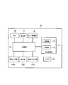
- FIG. 2 is a block diagram of the wireless terminal according to the present embodiment.
- the wireless terminal 10 includes a wireless communication unit 11, a card drive unit 14, an operation input unit 15A, a display unit 15B, a voice input / output unit 15C, a control unit 16, a processing unit 17, a memory 18, and a battery 19.
- the wireless terminal 10 is described as a configuration such as a smartphone or a mobile phone, but is not particularly limited to such a configuration.
- the wireless terminal 10 may be a wireless communication device such as a communication module.
- the block of the wireless terminal 10 shown in FIG. 2 simply shows the actual product.
- Various electronic components such as a module that implements GPS communication, wireless LAN, short-range communication, sensor communication, or an acceleration sensor may be mounted, but is omitted in this embodiment.
- the wireless communication unit 11 performs wireless communication corresponding to WWAN or WLAN.
- the wireless communication unit 11 is compatible with LTE and WiFi (registered trademark).
- a wireless communication unit for the second-generation or fifth-generation WWAN may be mounted on the wireless terminal 10.
- the radio communication unit 11 includes a transmission unit 12 and a reception unit 13, and transmits and receives radio signals to and from an antenna (not shown in FIG. 2) for communicating with the base station 4.
- the wireless communication unit 11 detects the network of the communication carrier via the base station of the network of the communication carrier.
- the transmission unit 12 encodes and modulates the data output from the control unit 16, and transmits the modulated data to the base station 4 as a radio signal.
- the receiving unit 13 When receiving a radio signal from the base station 4, the receiving unit 13 outputs a demodulated and decoded signal to the control unit 16 as data.
- the operation input unit 15A includes a touch screen, buttons, and the like, and inputs a command operated by the user.
- the display unit 15B is a display such as a touch screen.
- the voice input / output unit 15 ⁇ / b> C is a microphone that collects voice mainly required for a call and a speaker that outputs voice.
- the control unit 16 is a controller that controls electronic components mounted on the wireless terminal 10.
- a CPU Central Processing Unit
- ROM Read Only Memory
- RAM Random Access Memory
- RAM Backup RAM
- I / O Input / Output
- the processing unit 17 includes an OS (Operating System) that is software that implements the basic functions of a computer, and the software is executed by the control unit 16.
- the processing unit 17 executes functions for basic management and control of electronic components mounted on the wireless terminal 10 and a lot of software in common, and executes software for managing the entire system.
- the processing unit 17 controls the wireless communication unit 11 to execute processing necessary for connection with the base station and various services.
- the processing unit 17 processes protocols such as SIP (Session Initiation Protocol), RTP (Real-time Transport Protocol), and UDP / IP described below.
- the memory 18 stores programs and information necessary for controlling the wireless terminal 10.
- the memory 18 is configured by a nonvolatile memory, a flash memory, an EEPROM (ElectronicallyrasErasable and ProgrammablemRead Only Memory), or the like.
- the memory 18 is simply illustrated as one block, but may be configured by a plurality of storage media as described above.
- the memory 18 stores setting information necessary for wireless communication.
- the setting information includes information for connecting to a base station corresponding to the communication carrier.
- the memory 18 may store various setting information such as information for registering location information and information regarding a telephone number in order to receive a telephone or data communication service.
- the wireless communication unit 11 performs wireless communication based on setting information stored in the memory 18.
- the wireless communication unit 11 performs processing for receiving a service such as telephone or data communication by connecting to a base station.
- the battery 19 is a rechargeable battery, for example, and supplies power to each electronic component mounted on the wireless terminal 10.
- the card drive unit 14 drives an IC card called an SIM card (or UIM card), that is, an information card.
- SIM card or UIM card
- the card drive unit 14 can take in and take out the SIM card.
- the card driving unit 14 reads the setting information recorded on the SIM card and writes it to the SIM card.
- the SIM card has user identification information (for example, IMSI) for identifying a subscriber, carrier identification information for identifying a subscribed communication carrier (own communication carrier: home communication carrier), and This is an IC card in which information related to available services subscribed to by the subscriber is recorded.
- IMSI user identification information
- carrier identification information for identifying a subscribed communication carrier
- This is an IC card in which information related to available services subscribed to by the subscriber is recorded.
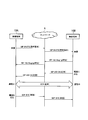
- FIG. 3 is a sequence diagram of the radio communication system according to the present embodiment.
- FIG. 5 is a sequence diagram of SIP when a user of the wireless terminal 10A transmits to a user of the wireless terminal 10B.
- the wireless terminal 10B sounds or vibrates a predetermined sound to notify the user.
- the state of the wireless terminal 10A and the wireless terminal 10B becomes busy.
- voice data and the like are transmitted and received by the radio terminal 10A and the radio terminal 10B by RTP.
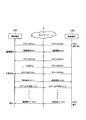
- FIG. 4 is a sequence diagram during a call in the wireless communication system according to the present embodiment.
- voice data communicated by the user of the wireless terminal 10A is transmitted to the wireless terminal 10B by RTP over UDP (step S1).
- step S2 if the communication quality of the wireless communication path between the wireless terminal 10B and the network 8 is poor, the sound is interrupted, so the user of the wireless terminal 10B presses the button on the operation input unit 15A of the wireless terminal 10B, Press and hold (step S2).
- wireless local area network wireless LAN
- D2D direct communication
- the processing unit 17 of the wireless terminal 10B transmits an accumulation request for allowing the wireless terminal 10A to accumulate RTP voice data transmitted from the wireless terminal 10B to the wireless terminal 10A (steps S3 and S4).
- the processing unit 17 of the wireless terminal 10A starts to accumulate RTP audio data transmitted from the wireless terminal 10B in the memory 18 of the wireless terminal 10A.
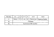
- FIG. 5 is a diagram showing an example of the configuration of the RTP packet header.
- the transmission side displays an order by a sequence number (Sequence number). Further, it is defined that the voice codec (codec) and the like are displayed according to the value of Payload type.
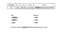
- FIG. 6 is a diagram showing another example of the configuration of the RTP packet header.
- the bit Bit 32 offset 32 data of this header is defined as shown in FIG. .
- the storage request described above is set to start with Type set to 1, and set Req / Res to 1.
- step S5 the voice data that the user of the wireless terminal 10B talks is transmitted to the wireless terminal 10A by RTP over UDP.
- step S7 when the voice data communicated by the user of the wireless terminal 10B is transmitted to the wireless terminal 10A by RTP over UDP (step S7), the communication quality of the wireless communication path with the wireless terminal 10BA network 8 is high. If it is bad, audio data by RTP is lost (step S8).
- the voice data with which the user of the wireless terminal 10B talks is transmitted to the wireless terminal 10A by RTP over UDP (steps S9 and S10).
- the processing unit 17 of the wireless terminal 10A recognizes that the audio data is missing because the sequence numbers of the audio data by RTP are not consecutive.
- the wireless terminal 10A has received the voice data of 100th.
- the sequence number of the voice data by RTP in step S8 is 101, but since the voice data has been lost, the wireless terminal 10A has not received the 101th voice data. Therefore, if the sequence number of the voice data by RTP in step S10 is 102, the wireless terminal 10A has received the 102nd voice data. Since the wireless terminal 10A receives the 102nd audio data after the 100th audio data, the wireless terminal 10A recognizes that the 101st audio data is missing.
- the processing unit 17 of the wireless terminal 10A When the processing unit 17 of the wireless terminal 10A recognizes that the voice data is missing, the processing unit 17 transmits a retransmission request to the wireless terminal 10B to retransmit the missing voice data to the wireless terminal 10B (steps S10 and S12). . Next, when receiving the retransmission request, the processing unit 17 of the wireless terminal 10B retransmits the missing voice data to the wireless terminal 10A (steps S13 and S14).
- Sequence number sequence number to be retransmitted
- the number 101 of the missing audio data becomes SequenceSnumber.
- the button 17 is released and the processing unit 17 of the wireless terminal 10B Is transmitted to the wireless terminal 10A to end the storage of the voice data by the wireless terminal 10A (steps S15 and S16).
- the payload type shown in FIG. 5 is an undefined value (here, the value is Z as an example), and the payload type is Z, the accumulation end described above starts accumulation with Type set to 2, A request is made with Req / Res set to 1.
- step S16 when the processing unit 17 of the wireless terminal 10A receives the end of accumulation, the user of the wireless terminal 10A can hear the reproduced sound by reproducing the accumulated audio data.
- the transmission and reception are like a transceiver, and a call (conversation) is established by repeating this operation.
- the wireless communication system in the real-time communication such as a voice call, when the communication quality such as a call state that is difficult to hear is deteriorated, the lost voice data is transferred to the partner wireless terminal 10B. Since the audio data is accumulated after being retransmitted, the audio can be heard. Therefore, when the communication quality such as a call state that is difficult to hear decreases, it is possible to avoid the communication service from being disabled and maintain the communication service.
- the determination when the communication quality is degraded is made by the user pressing the button on the operation input unit 15A when the sound is severely interrupted and difficult to hear.
- the communication quality has deteriorated when it is detected that more than a certain amount of audio data has been lost in a certain time or that more than a certain amount of continuous audio data has been lost.
- the processing unit 17 may determine (automatic communication deterioration detection).
- the processing unit 17 of the wireless terminal 10 may output a display indicating whether or not the voice data is stored to the display unit 15B.
- the processing unit 17 of the wireless terminal 10 may output the fact that it is in the accumulation state by voice through the voice input / output unit 15C. Further, both of the wireless terminals 10A and 10B may be in an accumulation state.
- the stored data may be reproduced when the storage capacity limit is reached. This is also a measure to prevent the silent time on the receiving side from becoming too long. Furthermore, if the receiving side wireless terminal 10 does not mute in the accumulated state and outputs a specific sound or a melody, it can be recognized that the receiving side person is in a silent state.
- in-network equipment is not required to be changed and can be handled with existing equipment.
- the voice data of the RTP packet is transparently delivered to the partner terminal by the network.
- the audio data described in the present embodiment may be replaced with video data and both.
Landscapes
- Engineering & Computer Science (AREA)
- Signal Processing (AREA)
- Computer Networks & Wireless Communication (AREA)
- Telephone Function (AREA)
- Mobile Radio Communication Systems (AREA)
Abstract
ネットワーク8を介して無線通信を行う無線端末10Aおよび無線端末10Bを有する無線通信システムにおいて、無線端末10Aおよび無線端末10Bがネットワーク8を介して音声データによる通信を行っている際に、無線端末10Bは、無線端末10Aに音声データの蓄積の要求を行い、蓄積の要求を受けた無線端末10Aは、無線端末10Bから送信された音声データを蓄積すると共に、音声データが欠落した場合、無線端末10Bに音声データの再送の要求を行い、再送の要求を受けた無線端末10Bは、欠落した音声データを無線端末10Aに再送し、無線端末10Bは、無線端末10Aに蓄積の終了の要求を行う。
Description
本開示は、VoIP(Voice over Internet Protocol)の通信技術に関する。
無線端末間でリアルタイム通信のアプリケーションであるVoIPによる通話がなされる技術が知られている(例えば特許文献1)。近年、3GPP(3rd Generation Partnership Project)の規格であるLTE(Long Term Evolution)が普及しており、ユーザが通話する際には、LTEを使用したVoLTE(Voice over LTE)という技術が使用されることもある。
VoLTEは、VoIPを実現する技術の1つとして注目されている。また、LTEの代わりに、無線ローカルネットワーク、例えばWi-Fi(登録商標)経由でも使用可能なVoIPを利用するSkype(登録商標)またはLINE(登録商標)は、ユーザによく使用されている。
一方で、天災や消防時に人命救助などで導入されるパブリックセーフティの整備が急務となっており、VoLTEを含むVoIPは、自営による無線通信システムで導入される構想もある。
本開示の無線通信システムは、無線通信を行う第1の無線端末および第2の無線端末を有する無線通信システムであって、前記第1の無線端末および前記第2の無線端末が音声データによる通信を行っている際に、前記第2の無線端末は、前記第1の無線端末に音声データの蓄積の要求を行い、前記蓄積の要求を受けた第1の無線端末は、前記第2の無線端末から送信された音声データを蓄積すると共に、音声データが欠落した場合、前記第2の無線端末に音声データの再送の要求を行い、前記再送の要求を受けた第2の無線端末は、欠落した音声データを前記第1の無線端末に再送し、前記第2の無線端末は、前記第1の無線端末に前記蓄積の終了の要求を行う。
VoIPの詳細については、音声データのプロトコルとして、IP(Internet Protocol)上のUDP(User Datagram Protocol)が用いられる。UDP/RTP(Real-Time Transport Protocol)は、通信相手にデータが送達されたか否かを確認する動作である送達確認は行われない。
音声データが非確認型の通信であるため、無線通信路が弱電界などで通信品質が悪いときに、音声データが欠落すると音声が途切れ聞き取りにくい現象が発生する。また、無線ローカルネットワーク経由で通信している場合には、他の無線ローカルネットワークとの無線干渉などで無線伝搬経路が影響を受け易く、そのような要因で通信品質が悪いときには同様の現象が顕著に発生する。
VoLTEの場合、LTE無線区間の必要な音声帯域を確保する仕組みがあるので、その様な事象は発生しにくいが、無線劣化が著しい場合には帯域確保できなくなり、同様の現象が発生する。
特に、パブリックセーフティの無線通信システムでは、災害時に通信品質が悪い状況が発生することで、音声が途切れ聞き取りにくい現象が多発することが想定される。
本開示は、音声通話などのリアルタイム通信において、聞き取りにくい通話状態などの通信品質が低下したときに、音声を聞き取ることができるよう、通信サービスを維持することができる無線通信システム、無線通信方法、および無線端末を提供するものである。
以下、本実施の形態について、図面を参照して説明する。
図1は、本実施の形態に係る無線通信システムの構成図である。図1に示した無線通信システムは、無線端末10およびネットワーク8を有している。以降、無線端末10を区別せず説明するときには、単に無線端末10と記載し、無線端末10を区別して説明するときには、無線端末10A、10Bと記載する。
無線通信システムは、パブリックセーフティのためのものでもよいし、公衆のためでもよい。また、無線端末10とネットワーク8との間の通信は、無線ローカルエリアネットワーク(WLAN:Wireless Local Area Network)でなされてもよい。WLANは、WiFi(登録商標)に対応したものでもよい。
さらに、無線通信システムは、ネットワーク8を用いずに、無線端末10Aと無線端末10Bとの間で直接に通信するようにしてもよい。無線端末10Aと無線端末10Bとの間の直接通信は、LTEによるD2D(Device to Device)などがある。また、無線端末10とネットワーク8との間の通信は、無線広域エリアネットワーク(WWAN:Wireless Wide Area Network)でなされてもよいし、例えば、WWANは、LTEに対応したものでもよい。
無線端末10は、例えば、スマートフォン、タブレット、または携帯電話機等である。無線端末10は、通信モジュールのような無線通信機器でもよい。
図2は、本実施例に係る無線端末のブロック図である。無線端末10は、無線通信部11、カード駆動部14、操作入力部15A、表示部15B、音声入出力部15C、制御部16、処理部17、メモリ18、およびバッテリ19を有している。本実施の形態では、無線端末10をスマートフォンまたは携帯電話機のような構成として説明しているが、特にそのようなものに限定することはない。無線端末10は、通信モジュールのような無線通信機器でもよい。
図2で示した無線端末10のブロックは、実製品を簡易的に示したものである。GPS通信、無線LAN、近距離通信、センサ通信等を実現するモジュール、または加速度センサなど多種多様な電子部品も実装される場合もあるが、本実施例では省略している。
無線通信部11は、WWANまたはWLANに対応した無線通信を行う。例えば、無線通信部11は、LTEやWiFi(登録商標)に対応したものである。ここでは図示をしていないが、さらに第2世代または第5世代のWWANのための無線通信部を無線端末10に搭載してもよい。
無線通信部11は、送信部12および受信部13によって構成され、基地局4と通信するためのアンテナ(図2では図示していない)と無線信号を送受信する。無線通信部11は、通信事業者のネットワークの基地局を介して通信事業者のネットワークを検出する。
送信部12は、制御部16から出力されたデータを符号化・変調し、変調されたものを無線信号として基地局4に送信する。受信部13は、基地局4から無線信号を受信した場合、その信号を復調・復号したものをデータとして制御部16に出力する。
操作入力部15Aは、タッチスクリーンやボタンなどから構成され、ユーザによって操作された命令を入力する。表示部15Bは、タッチスクリーンなどのディスプレイである。音声入出力部15Cは、主に通話で必要となる音声を収音するマイクロフォンおよび音声を出力するスピーカである。
制御部16は、無線端末10に実装される電子部品を制御するコントローラであり、例えばプログラムを実行するCPU(Central Processing Unit)、ROM(Read Only Memory)、RAM(Random Access Memory)、バックアップRAM、I/O(Input / Output)等よりなるマイクロコンピュータを主体として構成される。
処理部17は、コンピュータの基本的な機能などを実装したソフトウェアであるOS(Operating System)を含み、そのソフトウェアは、制御部16によって実行される。処理部17は、無線端末10に実装される電子部品の基本的な管理や制御のための機能、および、多くのソフトウェアが共通して利用でき、システム全体を管理するソフトウェアを実行する。
また、本実施の形態では、処理部17は、無線通信部11を制御することで、基地局との接続、および、種々のサービスに必要な処理を実行する。例えば、処理部17は、以降で説明するSIP(Session Initiation Protocol)、RTP(Real-time Transport Protocol)、UDP/IPなどのプロトコルを処理する。
メモリ18は、無線端末10を制御する上で必要なプログラムおよび情報を記憶している。例えば、メモリ18は、不揮発性メモリ、フラッシュメモリ、EEPROM(Electronically Erasable and Programmable Read Only Memory)などによって構成される。メモリ18は、簡易的に1つのブロックで図示しているが、上述のような複数の記憶媒体によって構成されてもよい。
メモリ18には、無線通信を行う上で必要な設定情報が記憶されている。例えば、設定情報には、通信事業者に対応した基地局と接続を行うための情報がある。また、メモリ18には、電話またはデータ通信のサービスを受けるため、位置情報を登録する際の情報、電話番号に関する情報など様々な設定情報が記憶されていてもよい。例えば、無線通信部11は、メモリ18に記憶されている設定情報に基づいて無線通信を行う。例えば、無線通信部11は、基地局と接続を行い、電話またはデータ通信などのサービスを受ける処理を実行する。
バッテリ19は、例えば充電池であり、無線端末10に実装される各電子部品に電力を供給するものである。
カード駆動部14は、SIMカード(またはUIMカード)と呼ばれるICカード、すなわち情報カードを駆動する。カード駆動部14は、SIMカードを取り込み、取り出しができる。カード駆動部14は、処理部17から設定情報の読み出しや書き込みを受けた場合、SIMカードに記録された設定情報の読み出し、SIMカードへの書き込みを行う。
SIMカードは、加入者を特定するためのユーザ識別情報(例えば、IMSIなど)、加入している通信事業者(自通信事業者:ホーム通信事業者)を特定するための事業者特定情報、および加入者が契約している利用可能なサービスに関する情報などが記録されたICカードである。
図3は、本実施の形態に係る無線通信システムのシーケンス図である。
無線端末10Aのユーザが、無線端末10Bのユーザに発信したときのSIPのシーケンス図である。無線端末10Bは、着信があると所定音を鳴動または振動してユーザに知らせる。
無線端末10Bのユーザが電話に出ると、無線端末10Aおよび無線端末10Bの状態が通話中となる。通話中の間は、ユーザが通話すると、RTPにて音声データなどが互いに無線端末10Aおよび無線端末10Bによって送受信される。
また、無線端末10Aのユーザが電話を切ると、無線端末10Aおよび無線端末10Bの通話は終了する。
図4は、本実施の形態に係る無線通信システムの通話中のシーケンス図である。
まず、無線端末10Aのユーザが通話した音声データが、UDP上のRTPにて無線端末10Bに送信される(ステップS1)。
その際、無線端末10Bとネットワーク8との間の無線通信路の通信品質が悪いと、音が途切れたりするため、無線端末10Bのユーザは、無線端末10Bの操作入力部15Aのボタンを押し、押したままにする(ステップS2)。ここでは、無線ローカルエリアネットワーク(無線LAN)や直接通信(D2D)等で、一般的に音途切れが発生したら相手にも発生している前提として、無線端末10Bのユーザが操作入力部15Aのボタンを押すことにしている。
無線端末10Bの処理部17は、無線端末10Bから送信されるRTPによる音声データを無線端末10Aに蓄積してもらうための蓄積要求を無線端末10Aに送信する(ステップS3、S4)。無線端末10Aの処理部17は、蓄積要求を受信すると、無線端末10Bから送信されるRTPの音声データを、無線端末10Aのメモリ18への蓄積を開始する。
図5は、RTPのパケットヘッダの構成の一例を示した図である。
図5に示すように、送信側は、シーケンス番号(Sequence number)によって順序を表示することが定義されている。さらに、Payload typeの値によって、パケットのボディ部がどのような音声コーデック(codec)に従っているか等を表示することが定義されている。
図6は、RTPのパケットヘッダの構成の別例を示した図である。
図5に示したpayload typeを未定義の値(ここでは一例として値をZとする)を使用し、payload typeがZだった場合、このヘッダのBit offset32のデータを図6のように定義する。上述した蓄積要求は、Typeを1として蓄積開始、Req/Resを1として要求とする。
次に、無線端末10Bのユーザが通話した音声データは、UDP上のRTPにて無線端末10Aに送信される(ステップS5、S6)。ここで、無線端末10Bのユーザが通話した音声データは、UDP上のRTPにて無線端末10Aに送信されたとき(ステップS7)、無線端末10BAネットワーク8との間の無線通信路の通信品質が悪いと、RTPによる音声データが欠落する(ステップS8)。
次に、無線端末10Bのユーザが通話した音声データは、UDP上のRTPにて無線端末10Aに送信される(ステップS9、S10)。無線端末10Aの処理部17は、RTPによる音声データのシーケンス番号が連続したものではないため、音声データが欠落することを認識する。
例えば、ステップS6でのRTPによる音声データのシーケンス番号が100番だとすると、無線端末10Aは、100番の音声データを受け取っている。ステップS8でのRTPによる音声データのシーケンス番号が101番であるが、その音声データは欠落したため、無線端末10Aは、101番の音声データを受け取っていない。そこで、ステップS10でのRTPによる音声データのシーケンス番号が102番だとすると、無線端末10Aは、102番の音声データを受け取っている。無線端末10Aは、100番の音声データの次に102番の音声データを受け取っているため、101番の音声データが欠落することを認識する。
無線端末10Aの処理部17は、音声データが欠落することを認識したとき、欠落した音声データを無線端末10Bに再送してもらうための再送要求を無線端末10Bに送信する(ステップS10、S12)。次に、無線端末10Bの処理部17は、再送要求を受信したとき、欠落した音声データを無線端末10Aに再送する(ステップS13、S14)。
例えば、図5に示したpayload typeを未定義の値(ここでは一例として値をZとする)を使用し、payload typeがZだった場合、上述した再送要求は、Typeを3として蓄積開始、Req/Resを1として要求とする。この場合、図6のSequence number(再送要求の対象となるシーケンス番号)は、欠落した音声データのシーケンス番号となる。上述した例では、欠落した音声データの101番がSequence numberになる。
その後、無線端末10Bとネットワーク8との間の無線通信路の通信品質が改善されたと無線端末10Bのユーザが感じたとき、押したままのボタンを離し、無線端末10Bの処理部17は、RTPによる音声データの蓄積を無線端末10Aに終了させるための蓄積終了を無線端末10Aに送信する(ステップS15、S16)。
例えば、図5に示したpayload typeを未定義の値(ここでは一例として値をZとする)を使用し、payload typeがZだった場合、上述した蓄積終了は、Typeを2として蓄積開始、Req/Resを1として要求とする。
ステップS16にて、無線端末10Aの処理部17は蓄積終了を受信すると、蓄積した音声データを再生することにより、無線端末10Aのユーザは再生された音声を聞くことができる。このように、操作入力部15Aのボタンを押したり離したりすることで、送話および受話はトランシーバのようであり、この繰り返しで通話(会話)が成立する。
以上説明したように、本実施の形態に係る無線通信システムでは、音声通話などのリアルタイム通信において、聞き取りにくい通話状態などの通信品質が低下したときに、欠落した音声データを相手の無線端末10Bに再送してもらい、音声データを蓄積するため、音声を聞き取ることができる。以って、聞き取りにくい通話状態などの通信品質が低下したときに、通信サービスが不能に陥ることを避けて、通信サービスを維持することができる。
(通信劣化の判定)
本実施の形態では、通話が劣化するなど通信品質が低下した場合の判断については、音途切れが激しくて聞き取りにくい際にユーザが操作入力部15Aのボタンを押すことでなされていた。しかしながら、ユーザの主観的な判断とは別に、一定時間に一定以上の音声データが欠落したこと、または、連続した一定以上の音声データが欠落したことを検出したときに、通信品質が低下したと処理部17が判断してもよい(自動通信劣化検出)。
本実施の形態では、通話が劣化するなど通信品質が低下した場合の判断については、音途切れが激しくて聞き取りにくい際にユーザが操作入力部15Aのボタンを押すことでなされていた。しかしながら、ユーザの主観的な判断とは別に、一定時間に一定以上の音声データが欠落したこと、または、連続した一定以上の音声データが欠落したことを検出したときに、通信品質が低下したと処理部17が判断してもよい(自動通信劣化検出)。
(蓄積への切換)
本実施の形態では、ユーザがボタンを押すことにより送話の音声データの蓄積が開始されたが、上記の自動通信劣化検出の場合は、無線端末10は、通信劣化を検出し、かつ、送話の音声データがある場合、相手端末に蓄積を要求する。なお、無線端末10は、送話の音声データが無くなったら相手端末に蓄積終了を要求してもよい。
本実施の形態では、ユーザがボタンを押すことにより送話の音声データの蓄積が開始されたが、上記の自動通信劣化検出の場合は、無線端末10は、通信劣化を検出し、かつ、送話の音声データがある場合、相手端末に蓄積を要求する。なお、無線端末10は、送話の音声データが無くなったら相手端末に蓄積終了を要求してもよい。
無線端末10の処理部17は、音声データを蓄積している蓄積状態になっているか否かを示す表示を表示部15Bに出力してもよい。また、無線端末10の処理部17は、蓄積状態になっていることを音声入出力部15Cによって音声で出力してもよい。また、無線端末10A、10Bの双方が、蓄積状態になっていてもよい。
(蓄積データの再生)
受話側の無線端末10では、蓄積容量の制限に達したら蓄積データを再生させてもよい。これは受話側の無音時間が長くなりすぎることを防止する対策でもある。さらに、蓄積状態において受話側の無線端末10が無音にせず、特定の音またはメロディ等を出力させれば、受話側の人が無音状態であることを認識できる。
受話側の無線端末10では、蓄積容量の制限に達したら蓄積データを再生させてもよい。これは受話側の無音時間が長くなりすぎることを防止する対策でもある。さらに、蓄積状態において受話側の無線端末10が無音にせず、特定の音またはメロディ等を出力させれば、受話側の人が無音状態であることを認識できる。
(その他の実施形態)
本実施の形態に係る無線通信システムでは、網内設備は変更不要で既存のもので対応可能である。RTP パケットの音声データは、網によって透過的に相手端末に送達される。以上本実施の形態で説明した音声データは、映像データおよびこれらの双方に替えてもよい。
本実施の形態に係る無線通信システムでは、網内設備は変更不要で既存のもので対応可能である。RTP パケットの音声データは、網によって透過的に相手端末に送達される。以上本実施の形態で説明した音声データは、映像データおよびこれらの双方に替えてもよい。
以上、図面を参照して実施形態について詳しく説明したが、具体的な構成は上述のものに限られることはなく、要旨を逸脱しない範囲内において様々な設計変更等をすることが可能である。
なお、本願は日本国特許出願第2018-022860号(2018年2月13日出願)の優先権を主張し、その内容の全てが本願明細書に組み込まれている。
Claims (10)
- 無線通信を行う第1の無線端末および第2の無線端末を有する無線通信システムであって、
前記第1の無線端末および前記第2の無線端末が音声データによる通信を行っている際に、前記第2の無線端末は、前記第1の無線端末に音声データの蓄積の要求を行い、
前記蓄積の要求を受けた前記第1の無線端末は、前記第2の無線端末から送信された音声データを蓄積すると共に、音声データが欠落した場合、前記第2の無線端末に音声データの再送の要求を行い、
前記再送の要求を受けた前記第2の無線端末は、欠落した音声データを前記第1の無線端末に再送し、
前記第2の無線端末は、前記第1の無線端末に前記蓄積の終了の要求を行う無線通信システム。 - 無線通信を行う第1の無線端末および第2の無線端末を有する無線通信システムの無線通信方法であって、
前記第1の無線端末および前記第2の無線端末が音声データによる通信を行っている際に、前記第2の無線端末は、前記第1の無線端末に音声データの蓄積の要求を行うステップと、
前記蓄積の要求を受けた前記第1の無線端末は、前記第2の無線端末から送信された音声データを蓄積すると共に、音声データが欠落した場合、前記第2の無線端末に音声データの再送の要求を行うステップと、
前記再送の要求を受けた前記第2の無線端末は、欠落した音声データを前記第1の無線端末に再送するステップと、
前記第2の無線端末は、前記第1の無線端末に前記蓄積の終了の要求を行うステップとを有する無線通信方法。 - 第1の無線端末と無線通信を行う無線通信部と、
前記第1の無線端末と音声データによる通信を行っている際に、前記第1の無線端末に音声データの蓄積の要求を行う処理部とを備え、
前記蓄積の要求を受けた前記第1の無線端末が、音声データが欠落し、音声データの再送の要求を行ったとき、前記処理部は、欠落した音声データを前記第1の無線端末に再送する第2の無線端末。 - ユーザの操作が入力される操作入力部を備え、
前記処理部は、前記操作に応じて前記第1の無線端末に音声データの蓄積の要求を行う請求項3に記載の第2の無線端末。 - 前記処理部は、前記操作に応じて前記第1の無線端末に前記蓄積の終了の要求を行う請求項4に記載の第2の無線端末。
- 前記処理部は、前記第1の無線端末との通信の通信品質が低下した場合、前記第1の無線端末に音声データの蓄積の要求を行う請求項3に記載の第2の無線端末。
- 前記処理部は、前記第1の無線端末との通信の通信品質が改善した場合、前記第1の無線端末に音声データの蓄積の終了の要求を行う請求項6に記載の第2の無線端末。
- 第2の無線端末と無線通信を行う無線通信部と、
前記第2の無線端末と音声データによる通信を行っている際に、前記第2の無線端末から音声データの蓄積の要求がなされたとき、前記第2の無線端末から送信された音声データを蓄積すると共に、音声データが欠落した場合、前記第2の無線端末に音声データの再送の要求を行う処理部とを備え、
前記第2の無線端末が欠落した音声データを再送したとき、前記処理部は、再送した音声データを蓄積する第1の無線端末。 - 前記第2の無線端末から前記蓄積の終了の要求がなされたとき、前記処理部は、蓄積された音声データを再生する請求項8に記載の第1の無線端末。
- 表示部を備え、
前記処理部は、音声データを蓄積している蓄積状態になっているか否かを示す表示を前記表示部に出力する請求項8に記載の第1の無線端末。
Applications Claiming Priority (2)
| Application Number | Priority Date | Filing Date | Title |
|---|---|---|---|
| JP2018-022860 | 2018-02-13 | ||
| JP2018022860 | 2018-02-13 |
Publications (1)
| Publication Number | Publication Date |
|---|---|
| WO2019159751A1 true WO2019159751A1 (ja) | 2019-08-22 |
Family
ID=67619376
Family Applications (1)
| Application Number | Title | Priority Date | Filing Date |
|---|---|---|---|
| PCT/JP2019/003993 Ceased WO2019159751A1 (ja) | 2018-02-13 | 2019-02-05 | 無線通信システム、無線通信方法、および無線端末 |
Country Status (1)
| Country | Link |
|---|---|
| WO (1) | WO2019159751A1 (ja) |
Citations (1)
| Publication number | Priority date | Publication date | Assignee | Title |
|---|---|---|---|---|
| JP2016525841A (ja) * | 2013-07-23 | 2016-08-25 | ココ・コミュニケーションズ・コーポレーション | ボイスオーバー・インターネットプロトコル・ネットワーク上でのプッシュ・ツー・トーク音声通信のためのシステムおよび方法 |
-
2019
- 2019-02-05 WO PCT/JP2019/003993 patent/WO2019159751A1/ja not_active Ceased
Patent Citations (1)
| Publication number | Priority date | Publication date | Assignee | Title |
|---|---|---|---|---|
| JP2016525841A (ja) * | 2013-07-23 | 2016-08-25 | ココ・コミュニケーションズ・コーポレーション | ボイスオーバー・インターネットプロトコル・ネットワーク上でのプッシュ・ツー・トーク音声通信のためのシステムおよび方法 |
Similar Documents
| Publication | Publication Date | Title |
|---|---|---|
| CN103314624B (zh) | 多sim ue响应于接收到呼叫而发送繁忙状态消息的方法和装置 | |
| US8878889B1 (en) | Method and system for originating and receiving emergency push-to-talk calls | |
| US8103240B2 (en) | Communication system and mobile wireless communication device | |
| CN113395785A (zh) | 一种辅助链路补偿通话的系统、装置及芯片 | |
| EP2536117A1 (en) | Method and apparatus for establishing circuit switched link of wifi handheld equipment | |
| JP5853789B2 (ja) | 通信装置、通信システム、および通信方法 | |
| US7725136B2 (en) | Information processing apparatus | |
| JP2005117141A (ja) | 半二重無線通信装置、システムおよび方法 | |
| CN101180876B (zh) | 用于通信系统的电子设备 | |
| JP2008516512A (ja) | 無線通信ゲートウェイ及び無線通信端末 | |
| CN104038258A (zh) | 电话连接方法、电子终端以及系统 | |
| US8515458B2 (en) | Wireless telephone system, relay device, and wireless telephone device | |
| JP4224359B2 (ja) | 移動局 | |
| EP3843370B1 (en) | Relay device and voice communication recording method | |
| JP6012090B1 (ja) | 無線通信中継装置、無線通信中継装置における自動応答方法および自動応答プログラム | |
| WO2019159751A1 (ja) | 無線通信システム、無線通信方法、および無線端末 | |
| JP4877952B2 (ja) | 無線lanを利用した音声通話システム、無線端末及び中継装置 | |
| JP5769909B2 (ja) | 無線通信装置およびサーバ装置 | |
| JP4941789B2 (ja) | ホームゲートウェイ装置および番号ポータビリティ制御方法 | |
| JP2001045453A (ja) | 画像伝送装置 | |
| KR20010081872A (ko) | 무선 단말기의 음성 통화방법 및 이를 제공하는 방법 | |
| JP4276251B2 (ja) | 移動通信端末および移動通信端末の制御方法。 | |
| WO2021100258A1 (ja) | 音声通信システム、音声通信方法、および、音声通信プログラム | |
| JP5000355B2 (ja) | 無線通信端末、制御方法 | |
| JP4769686B2 (ja) | 移動無線端末装置 |
Legal Events
| Date | Code | Title | Description |
|---|---|---|---|
| 121 | Ep: the epo has been informed by wipo that ep was designated in this application |
Ref document number: 19753896 Country of ref document: EP Kind code of ref document: A1 |
|
| NENP | Non-entry into the national phase |
Ref country code: DE |
|
| 122 | Ep: pct application non-entry in european phase |
Ref document number: 19753896 Country of ref document: EP Kind code of ref document: A1 |
|
| NENP | Non-entry into the national phase |
Ref country code: JP |