WO2019159307A1 - インクジェット印刷装置 - Google Patents
インクジェット印刷装置 Download PDFInfo
- Publication number
- WO2019159307A1 WO2019159307A1 PCT/JP2018/005383 JP2018005383W WO2019159307A1 WO 2019159307 A1 WO2019159307 A1 WO 2019159307A1 JP 2018005383 W JP2018005383 W JP 2018005383W WO 2019159307 A1 WO2019159307 A1 WO 2019159307A1
- Authority
- WO
- WIPO (PCT)
- Prior art keywords
- maintenance
- inkjet head
- unit
- head
- slide mechanism
- Prior art date
- Legal status (The legal status is an assumption and is not a legal conclusion. Google has not performed a legal analysis and makes no representation as to the accuracy of the status listed.)
- Ceased
Links
Images









Classifications
-
- B—PERFORMING OPERATIONS; TRANSPORTING
- B41—PRINTING; LINING MACHINES; TYPEWRITERS; STAMPS
- B41J—TYPEWRITERS; SELECTIVE PRINTING MECHANISMS, i.e. MECHANISMS PRINTING OTHERWISE THAN FROM A FORME; CORRECTION OF TYPOGRAPHICAL ERRORS
- B41J2/00—Typewriters or selective printing mechanisms characterised by the printing or marking process for which they are designed
- B41J2/005—Typewriters or selective printing mechanisms characterised by the printing or marking process for which they are designed characterised by bringing liquid or particles selectively into contact with a printing material
- B41J2/01—Ink jet
-
- B—PERFORMING OPERATIONS; TRANSPORTING
- B41—PRINTING; LINING MACHINES; TYPEWRITERS; STAMPS
- B41J—TYPEWRITERS; SELECTIVE PRINTING MECHANISMS, i.e. MECHANISMS PRINTING OTHERWISE THAN FROM A FORME; CORRECTION OF TYPOGRAPHICAL ERRORS
- B41J2/00—Typewriters or selective printing mechanisms characterised by the printing or marking process for which they are designed
- B41J2/005—Typewriters or selective printing mechanisms characterised by the printing or marking process for which they are designed characterised by bringing liquid or particles selectively into contact with a printing material
- B41J2/01—Ink jet
- B41J2/135—Nozzles
- B41J2/165—Prevention or detection of nozzle clogging, e.g. cleaning, capping or moistening for nozzles
Definitions
- the present disclosure relates to an inkjet printing apparatus.
- Patent Document 1 the technique described in Patent Document 1 below is an ink jet recording apparatus, in which a nozzle forming surface provided with a nozzle for discharging an ink composition containing an inorganic pigment is provided, and a liquid repellent provided on the nozzle forming surface.
- a recording head provided with a film, a maintenance means for maintaining the recording head, and the nozzle forming surface and the maintenance means are arranged at opposing positions so that the nozzle forming surface and the maintenance means are relatively
- a moving section that moves the cleaning means, and the maintenance means includes a cleaning liquid applying means for applying a cleaning liquid to the nozzle forming surface, an absorbing member for absorbing deposits adhering to the nozzle forming surface, and the absorbing member.
- a pressing mechanism that presses the recording head with a load of 8 gf / cm or more and 150 gf / cm or less, and the absorbing member is compatible with the nozzle formation surface.
- a wiping unit having a driving mechanism for wiping the deposit of the nozzle forming surface to move.
- the present disclosure has been made in view of the above-described points, and even if the number of maintenance units that perform maintenance of the inkjet head is increased, the moving distance of the inkjet head that is necessary when performing maintenance of the inkjet head is increased. It is an object to provide a constant inkjet printing apparatus.
- an inkjet head provided so as to be movable along a first guide between a discharge position for discharging resin or ink used in three-dimensional additive manufacturing and a maintenance position where maintenance is performed;
- a maintenance unit that is movable along a second guide that intersects with the guide and that performs maintenance of the inkjet head, and a maintenance unit that is one of the plurality of maintenance units and is a maintenance target.
- An ink jet printing apparatus including a control unit that moves the printer to a maintenance position is disclosed.
- the moving distance of the ink jet head necessary for performing maintenance of the ink jet head is constant.
- FIG. 1 It is a figure which shows a circuit formation apparatus. It is a block diagram which shows the control apparatus of a circuit formation apparatus. It is a block diagram which shows the control apparatus of a circuit formation apparatus. It is a figure which shows each operation
- FIG. 1 shows a circuit forming device 10.
- the circuit forming apparatus 10 includes a transport device 20, a first modeling unit 22, a second modeling unit 24, and a control device (see FIG. 2) 26.
- the conveying device 20, the first modeling unit 22, and the second modeling unit 24 are disposed on the base 28 of the circuit forming device 10.
- the base 28 has a generally rectangular shape.
- the longitudinal direction of the base 28 is orthogonal to the X-axis direction
- the short direction of the base 28 is orthogonal to both the Y-axis direction, the X-axis direction, and the Y-axis direction.
- the direction will be described as the Z-axis direction.
- the transport device 20 includes an X-axis slide mechanism 30 and a Y-axis slide mechanism 32.
- the X-axis slide mechanism 30 has an X-axis slide rail 34 and an X-axis slider 36.
- the X-axis slide rail 34 is disposed on the base 28 so as to extend in the X-axis direction.
- the X-axis slider 36 is held by an X-axis slide rail 34 so as to be slidable in the X-axis direction.
- the X-axis slide mechanism 30 has an electromagnetic motor (see FIG. 2) 38, and the X-axis slider 36 moves to an arbitrary position in the X-axis direction by driving the electromagnetic motor 38.
- the Y axis slide mechanism 32 includes a Y axis slide rail 50 and a stage 52.
- the Y-axis slide rail 50 is disposed on the base 28 so as to extend in the Y-axis direction.
- One end of the Y-axis slide rail 50 is connected to the X-axis slider 36.
- the Y-axis slide rail 50 is movable in the X-axis direction.
- a stage 52 is held on the Y-axis slide rail 50 so as to be slidable in the Y-axis direction.
- the Y-axis slide mechanism 32 has an electromagnetic motor (see FIG. 2) 56, and the stage 52 moves to an arbitrary position in the Y-axis direction by driving the electromagnetic motor 56.
- the stage 52 moves to an arbitrary position on the base 28 by driving the X-axis slide mechanism 30 and the Y-axis slide mechanism 32.
- the stage 52 has a base 60, a holding device 62, and a lifting device 64.
- the base 60 is formed in a flat plate shape, and a substrate is placed on the upper surface.
- the holding device 62 is provided on both sides of the base 60 in the X-axis direction. The both edges in the X-axis direction of the substrate placed on the base 60 are sandwiched between the holding devices 62, so that the substrate is fixedly held.
- the raising / lowering device 64 is arrange
- the first modeling unit 22 is a unit that models a wiring on a substrate placed on the base 60 of the stage 52, and includes a first printing unit 72 and a firing unit 74.
- the first printing unit 72 has an inkjet head (see FIG. 2) 76, and ejects metal ink in a linear form on a substrate placed on the base 60.
- the metal ink is obtained by dispersing metal fine particles in a solvent.
- the inkjet head 76 discharges a conductive material from a plurality of nozzles by, for example, a piezo method using a piezoelectric element.
- the firing unit 74 has a laser irradiation device (see FIG. 2) 78.
- the laser irradiation device 78 is a device that irradiates a metal ink ejected on a substrate with a laser, and the metal ink irradiated with the laser is baked to form a wiring.
- the firing of the metal ink is a phenomenon in which, by applying energy, the solvent is vaporized, the metal fine particle protective film is decomposed, etc., and the metal fine particles are contacted or fused to increase the conductivity. is there.
- metal wiring is formed by baking metal ink.
- the second modeling unit 24 is a unit that models a resin layer on the substrate placed on the base 60 of the stage 52, and includes a second printing unit 84 and a curing unit 86.
- the second printing unit 84 has an inkjet head (see FIG. 2) 88 and discharges an ultraviolet curable resin onto the substrate placed on the base 60.
- the ink jet head 88 may be, for example, a piezo method using a piezoelectric element, or a thermal method in which a resin is heated to generate bubbles and ejected from a nozzle.
- the curing unit 86 includes a flattening device (see FIG. 2) 90 and an irradiation device (see FIG. 2) 92.
- the flattening device 90 is for flattening the upper surface of the ultraviolet curable resin discharged onto the substrate by the ink jet head 88.
- the leveling device 90 is configured to smooth the surface of the ultraviolet curable resin while removing excess resin from the roller or blade. The thickness of the UV curable resin is made uniform by scraping.
- the irradiation device 92 includes a mercury lamp or an LED as a light source, and irradiates the ultraviolet curable resin discharged on the substrate with ultraviolet rays. Thereby, the ultraviolet curable resin discharged on the board
- the control device 26 includes a controller 120 and a plurality of drive circuits 122 as shown in FIG.
- the plurality of drive circuits 122 are connected to the electromagnetic motors 38 and 56, the holding device 62, the lifting device 64, the inkjet head 76, the laser irradiation device 78, the inkjet head 88, the flattening device 90, and the irradiation device 92.
- the controller 120 includes a CPU, a ROM, a RAM, and the like, is mainly a computer, and is connected to a plurality of drive circuits 122. Thereby, the operation of the transport device 20, the first modeling unit 22, and the second modeling unit 24 is controlled by the controller 120.
- a circuit pattern is formed on a substrate by the above-described configuration. Specifically, the substrate is set on the base 60 of the stage 52, and the stage 52 is moved below the second modeling unit 24. And in the 2nd printing part 84, a resin laminated body is formed on a board
- the stage 52 is moved below the first modeling unit 22.
- the inkjet head 76 discharges a metal ink on the upper surface of a resin laminated body linearly according to a circuit pattern.
- the circuit pattern is stored in the controller 120 as wiring formation data for forming a wiring, and the ink-jet head 76 is controlled based on the wiring formation data, so that the metal ink corresponds to the circuit pattern. Discharged.
- the laser irradiation device 78 irradiates the metal ink with a laser. Thereby, the metal ink is baked, and wiring is formed on the resin laminate.
- the resin laminate is formed with the ultraviolet curable resin, and the wiring is formed with the metal ions, whereby the circuit pattern is formed on the substrate.
- the first printing unit 72 includes a head slide mechanism 130 and a maintenance slide mechanism 132 for maintaining the inkjet head 76 (hereinafter referred to as “maintenance”). ing.
- the head slide mechanism 130 has an electromagnetic motor 134.
- the maintenance slide mechanism 132 has an electromagnetic motor 136.
- the controller 120 of the control device 26 is connected to the electromagnetic motor 134 of the head slide mechanism 130 and the electromagnetic motor 136 of the maintenance slide mechanism 132 via two drive circuits 122. Thereby, each operation of the head slide mechanism 130 and the maintenance slide mechanism 132 is controlled by the controller 120.
- the operations of the head slide mechanism 130 and the maintenance slide mechanism 132 in the first printing unit 72 will be described later.
- the second printing unit 84 includes a head slide mechanism 138 and a maintenance slide mechanism 140 for maintaining the inkjet head 88.
- the head slide mechanism 138 has an electromagnetic motor 142.
- the maintenance slide mechanism 140 has an electromagnetic motor 144.
- the controller 120 of the control device 26 is connected to the electromagnetic motor 142 of the head slide mechanism 138 and the electromagnetic motor 144 of the maintenance slide mechanism 140 via two drive circuits 122. Thereby, each operation of the head slide mechanism 138 and the maintenance slide mechanism 140 is controlled by the controller 120. Since the operations of the head slide mechanism 138 and the maintenance slide mechanism 140 are the same as the operations of the head slide mechanism 130 and the maintenance slide mechanism 132 in the first printing unit 72, the description thereof is omitted.
- the head slide mechanism 130 has a first guide rail 150.
- the ink jet head 76 is movable along the first guide rail 150 by driving the electromagnetic motor 134. Thereby, the inkjet head 76 moves between the discharge position EL (see FIG. 9) and the maintenance position ML (FIG. 4).
- the ejection position EL refers to the position of the inkjet head 76 when the inkjet head 76 ejects metal ink onto the substrate placed on the base 60 in the first printing unit 72. 4 to 8 is at the ejection position EL.
- the maintenance position ML refers to the position of the inkjet head 76 when the inkjet head 76 is maintained in the first printing unit 72.
- the ink jet head 76 shown in FIG. 9 is at the maintenance position ML.
- the maintenance slide mechanism 132 has a second guide rail 152.
- the second guide rail 152 is disposed below the first guide rail 150. Further, the second guide rail 152 is orthogonal to the first guide rail 150 in a state of three-dimensionally intersecting the first guide rail 150.
- the maintenance slide mechanism 132 includes a wiping unit 160, a capping unit 162, a flushing unit 164, and a purge unit 166 as maintenance units (hereinafter referred to as maintenance units) for maintaining the inkjet head 76.
- maintenance units maintenance units
- the wiping unit 160, the capping unit 162, the flushing unit 164, and the purge unit 166 are collectively referred to as maintenance units 160, 162, 164, and 166 when they are described without distinction.
- the wiping unit 160 performs maintenance (that is, wiping maintenance) for wiping the surface of the nozzle from which the metal ink is discharged (hereinafter referred to as the nozzle surface of the inkjet head 76) with a wiper (not shown) such as a waste cloth.
- the nozzle surface of the inkjet head 76 is covered with a lid, and maintenance for preventing the metal ink from drying (that is, capping maintenance) is performed.
- the flushing unit 164 for example, when the discharge of the metal ink becomes unstable due to drying, the maintenance that discharges the metal ink from the nozzles of the inkjet head 76 (that is, the metal ink is discarded and the maintenance of the flushing) is performed. Is done.
- the purge unit 166 forcibly discharges the metal ink from the nozzles of the inkjet head 76 by, for example, raising the internal pressure of the inkjet head 76 from the normal time when the discharge of the metal ink becomes impossible due to drying.
- Maintenance to be performed that is, purge maintenance
- the structure for performing these maintenance is a well-known technique, the detailed description is abbreviate
- the maintenance units 160, 162, 164, and 166 are provided adjacent to each other in the second guide rail 152, and are movable along the second guide rail 152 by driving the electromagnetic motor 136. Yes. As a result, the maintenance units 160, 162, 164, and 166 can move to the maintenance position ML.
- the wiping unit 160 is located at the maintenance position ML.
- the capping unit 162 is located at the maintenance position ML.
- the flushing unit 164 is located at the maintenance position ML.
- the purge unit 166 is located at the maintenance position ML.
- the maintenance units 160, 162, 164, 166 are located below the inkjet head 76.
- the control program shown in the flowchart of FIG. 10 is stored in the ROM of the controller 120, and is executed by the CPU of the controller 120 when the inkjet head 76 is maintained.
- the controller 120 first performs a maintenance unit movement process in step (hereinafter referred to as S) 10.
- a maintenance unit movement process in step (hereinafter referred to as S) 10.
- any one of the maintenance units 160, 162, 164, and 166 which is a maintenance target (hereinafter referred to as a maintenance target), is moved to the maintenance position ML.
- the controller 120 performs the first movement process of the inkjet head.
- the inkjet head 76 is moved from the discharge position EL to the maintenance position ML.
- the maintenance position ML the inkjet head 76 is positioned above the unit to be maintained.
- the unit to be maintained is the capping unit 162
- the inkjet head 76 is positioned above the capping unit 162 as shown in FIG.
- the controller 120 performs a maintenance process.
- maintenance by the maintenance target unit is performed on the inkjet head 76 at the maintenance position ML.
- the controller 120 determines whether or not the capping unit 162 is at the maintenance position ML. If the capping unit 162 is at the maintenance position ML (S16: YES), the controller 120 ends the control program shown in the flowchart of FIG. Thereby, at the maintenance position ML, the capping unit 162 continues the maintenance in which the nozzle surface of the inkjet head 76 is covered with the lid.
- the controller 120 performs the second movement process of the inkjet head in S18. In this process, after the maintenance in the maintenance process of S14 is completed, the inkjet head 76 is moved from the maintenance position ML to the discharge position EL. Thereafter, the controller 120 ends the control program shown in the flowchart of FIG.
- each maintenance of the inkjet head 76 is performed at the maintenance position ML. Therefore, the moving distance of the ink jet head 76 necessary for performing maintenance of the ink jet head 76 is constant without changing depending on the distance from the discharge position EL to the maintenance position ML. Therefore, in the circuit forming apparatus 10 of the present embodiment, even if the number of maintenance units that perform maintenance of the inkjet head 76 increases, if the maintenance unit corresponding to the increase is disposed on the second guide rail 152, the inkjet head It is possible to make the moving distance of the ink-jet head 76 necessary for performing the maintenance of 76 constant.
- the circuit forming apparatus 10 is an example of the inkjet printing apparatus of the present disclosure.
- the control device 26 is an example of a control unit of the present disclosure.
- the first guide rail 150 is an example of the first guide of the present disclosure.
- the second guide rail 152 is an example of the second guide of the present disclosure.
- Each maintenance unit of the wiping unit 160, the capping unit 162, the flushing unit 164, and the purge unit 166 is an example of a plurality of maintenance units of the present disclosure.
- the two inkjet heads 76 are distinguished by attaching an English letter A or B to the reference numeral 76.
- the two first guide rails 150 are distinguished by attaching an English letter A or B to the reference numeral 150.
- the two capping units 162 are distinguished by attaching an English letter A or B to the reference numeral 162.
- the two discharge positions EL are distinguished by attaching the numeral 1 or 2 to the EL of the reference numeral.
- the two maintenance positions ML are distinguished by attaching the number 1 or 2 to the ML of the sign.
- the present disclosure can be applied even when a plurality of inkjet heads 76 are integrated and movable along the first guide rail 150. However, in such a case, as many capping units 162 as the number of inkjet heads 76 are arranged on the second guide rail 152.
- the inkjet head 76A and the inkjet head 76B are connected.
- the ink jet head 76 ⁇ / b> A and the ink jet head 76 ⁇ / b> B are integrally movable along the first guide rail 150. Therefore, in the first modification, when the inkjet head 76A is at the ejection position EL1 (see FIG. 13), the inkjet head 76B is at the ejection position EL2 (see FIG. 13).
- the metal ink may be dried in the inkjet head 76B unless the inkjet head 76B at the maintenance position ML2 is also subjected to capping maintenance. .
- the inkjet head 76B has undergone capping maintenance at the maintenance position ML2
- the metal ink may dry in the inkjet head 76A. There is.
- the capping unit 162 ⁇ / b> A and the capping unit 162 ⁇ / b> B are provided so as to be adjacent to each other in the second guide rail 152. Therefore, in S10, when the controller 120 moves the capping unit 162A to the maintenance position ML1, the capping unit 162B moves to the maintenance position ML2. Alternatively, in S10, when the controller 120 moves the capping unit 162B to the maintenance position ML2, the capping unit 162A moves to the maintenance position ML1. Thereby, in the first modified example, as shown in FIG. 13, the inkjet head 76A can be maintained by the capping unit 162A, and at the same time, the inkjet head 76B can be maintained by the capping unit 162B.
- the wiping unit 160 is in the maintenance position ML1
- the capping unit 162A is in the maintenance position ML2.
- the present disclosure can be applied even when a plurality of inkjet heads 76 can be individually moved along the first guide rail 150.
- the first guide rails 150 corresponding to the number of inkjet heads 76 are provided in a state of being aligned with each other, and the capping units 162 corresponding to the number of inkjet heads 76 are disposed on the second guide rail 152. Is done.
- the inkjet head 76A is movable along the first guide rail 150A, and the inkjet head 76B is movable along the first guide rail 150B.
- the inkjet head 76A is at the ejection position EL1 (see FIG. 16) or the maintenance position ML1 (see FIG. 14)
- the inkjet head 76B is not ejected from the ejection position EL2 (see FIG. 16) or maintenance. It is possible to move to the position ML2 (see FIG. 14).
- the ink jet head 76A is discharged from the discharge position EL1 (see FIG. 16) or the maintenance position ML1 (see FIG. 14). It is possible to move on. That is, the inkjet head 76A and the inkjet head 76B can move individually.
- the first guide rail 150A and the first guide rail 150B are provided adjacent to each other (that is, arranged side by side), and the movement of the inkjet head 76A and the movement of the inkjet head 76B are performed in parallel. Accordingly, the interval L1 (see FIG. 14) between the maintenance position ML1 and the maintenance position ML2 is also the interval between the ejection position EL1 and the ejection position EL2, and is also the interval between the inkjet head 76A and the inkjet head 76B.
- the inkjet head 76A and the inkjet head 76B can move individually, for example, when the inkjet head 76A is undergoing capping maintenance at the maintenance position ML1, the inkjet head 76B is capped at the maintenance position ML2. There are times when you want to receive maintenance. Similarly, when the inkjet head 76B is undergoing capping maintenance at the maintenance position ML2, the inkjet head 76A may wish to undergo capping maintenance at the maintenance position ML1.
- the capping unit 162A and the capping unit 162B are provided in the second guide rail 152 through the wiping unit 160, and further, the maintenance position ML1 and the maintenance position ML2 are provided. And the same distance L2 as the distance L1 (see FIG. 14). Therefore, in S10, when the controller 120 moves the capping unit 162A to the maintenance position ML1, the capping unit 162B moves to the maintenance position ML2. Alternatively, in S10, when the controller 120 moves the capping unit 162B to the maintenance position ML2, the capping unit 162A moves to the maintenance position ML1. Thereby, in the second modified example, as shown in FIG. 16, when the inkjet head 76A is under maintenance by the capping unit 162A, the inkjet head 76B can be under maintenance by the capping unit 162B.
- the controller 120 when the maintenance of the inkjet head 76A or the inkjet head 76B is performed (except when the maintenance of the capping is simultaneously performed on the inkjet head 76A and the inkjet head 76B), the controller 120 is used. Performs the following processing in S10 and S12.
- the controller 120 determines that the maintenance target unit is one of the maintenance units 160, 162A, 162B, 164, and 166 at the maintenance position in S10. Move to ML1.
- the controller 120 moves the capping unit 162A or the capping unit 162B to the maintenance position ML1.
- the capping unit 162B is at the maintenance position ML1.
- the controller 120 moves the inkjet head 76A that is a maintenance target to the maintenance position ML1.
- the maintenance of the inkjet head 76A is performed at the maintenance position ML1 (S14). This is the same even when maintenance of the inkjet head 76B is performed at the maintenance position ML2.
- the present disclosure is different from the second modified example in that the capping units 162 corresponding to the number of the ink jet heads 76 are not disposed on the second guide rail 152, but a plurality of ink jet heads 76 are provided in the first guide.
- the present invention can be applied even when it is disposed at a position where it can move along the rail 150.
- the capping unit 162A is disposed at a position where the inkjet head 76A can move along the first guide rail 150A and is different from the maintenance position ML1.
- the capping unit 162B is disposed at a position where the inkjet head 76B can move along the first guide rail 150B and is different from the maintenance position ML2.
- the wiping unit 160, the flushing unit 164, and the purge unit 166 which are not the capping unit 162A and the capping unit 162B among the maintenance units, are provided in a state of being adjacent to each other.
- the controller 120 when capping maintenance is performed on the inkjet head 76A and the inkjet head 76B at the same time, the controller 120 performs the process of S12 without performing the process of S10. In step S12, the controller 120 moves the inkjet head 76A to the capping unit 162A (above), and further moves the inkjet head 76B to the capping unit 162B (above). As a result, in the third modified example, when the inkjet head 76A is under maintenance by the capping unit 162A, the inkjet head 76B can be under maintenance by the capping unit 162B.
- the inkjet head 76A has moved to (above) the capping unit 162A, and the inkjet head 76B has moved to (above) the wiping unit 160 at the maintenance position ML2. That is, the inkjet head 76A receives capping maintenance by the capping unit 162A, and the inkjet head 76B receives wiping maintenance by the wiping unit 160.
- the inkjet head 76A when the inkjet head 76A is under maintenance of the capping unit 162A, the inkjet head 76B receives maintenance of the wiping unit 160, the flushing unit 164, or the purge unit 166 at the maintenance position ML2. It is possible. Similarly, when the inkjet head 76B is under maintenance of the capping unit 162B, the inkjet head 76A can receive maintenance of the wiping unit 160, the flushing unit 164, or the purge unit 166 at the maintenance position ML1. is there.
- the third modified example can also be applied to the configuration shown in FIG.
- the first guide rail 150 ⁇ / b> A and the first guide rail 150 ⁇ / b> B are provided in a state of being separated and arranged, so that the inkjet head 76 ⁇ / b> A and the inkjet head 76 ⁇ / b> B are arranged to face each other.
- the third modified example can be applied to the configuration shown in FIG. In the configuration shown in FIG. 20, the first guide rail 150A and the first guide rail 150B are provided in a state of being spaced apart from each other, so that the inkjet head 76A and the inkjet head 76B are replaced by the first guide rail 150A and the first guide rail 150B. Are arranged in the same direction.
- the present disclosure is applied to the inkjet head 76 of the first printing unit 72, but the inkjet head 88 of the second printing unit 84 is used. Similarly, the present disclosure can be applied.
- the second guide rail 152 is not limited to a linear one, and may be, for example, an annular one. This also applies to the above-described first modification example, second modification example, and three modification examples.
- first guide rail 150 and the second guide rail 152 may be in a state of being three-dimensionally crossed at an angle other than a right angle. This also applies to the above-described first modification example, second modification example, and three modification examples.
- the maintenance unit may perform maintenance other than wiping, capping, flushing, and purging.
Landscapes
- Coating Apparatus (AREA)
- Ink Jet (AREA)
Abstract
3次元積層造形で使用される樹脂又はインクを吐出する吐出位置と保守が行われる保守位置との間を第1ガイドに沿って移動可能に設けられたインクジェットヘッドと、第1ガイドと立体交差する第2ガイドに沿って移動可能であり、インクジェットヘッドの保守を行う複数の保守ユニットと、複数の保守ユニットのいずれか一つの保守ユニットであって、保守の対象である保守ユニットを、保守位置に移動させる制御部とを備えるインクジェット印刷装置。
Description
本開示は、インクジェット印刷装置に関するものである。
近年、インクジェット印刷装置に関して、複数の保守ユニットのいずれか一つの保守ユニットを使用してインクジェットヘッドの保守を行う技術が、種々提案されている。
例えば、下記特許文献1に記載の技術は、インクジェット記録装置であって、無機顔料を含有するインク組成物を吐出するノズルが設けられたノズル形成面と、該ノズル形成面に設けられた撥液膜と、を備える記録ヘッドと、前記記録ヘッドを保守するためのメンテナンス手段と、前記ノズル形成面と前記メンテナンス手段とを対向する位置に配置して、前記ノズル形成面と前記メンテナンス手段とを相対的に移動させる移動部と、を有し、前記メンテナンス手段は、前記ノズル形成面に洗浄液を付与する洗浄液付与手段と、前記ノズル形成面に付着した付着物を吸収する吸収部材と、前記吸収部材と前記記録ヘッドとを8gf/cm以上150gf/cm以下の荷重で押し当てる押圧機構と、前記吸収部材を前記ノズル形成面に対して相対的に移動させて前記ノズル形成面の付着物を払拭する駆動機構と、を有する払拭手段と、を有している。
上記特許文献1に記載の技術では、ノズル形成面とメンテナンス手段とが相対的に移動するが、その移動方向において、メンテナンス手段を構成する洗浄液付与手段、吸収部材、押圧機構、及び駆動機構が配置されている。そのため、メンテナンス手段の数が増加するに連れて、ノズル形成面とメンテナンス手段とが相対的に移動する最長距離も増加する。
そこで、本開示は、上述した点を鑑みてなされたものであり、インクジェットヘッドの保守を行う保守ユニットの数が増加しても、インクジェットヘッドの保守を行う際に必要なインクジェットヘッドの移動距離が一定であるインクジェット印刷装置を提供することを課題とする。
本明細書は、3次元積層造形で使用される樹脂又はインクを吐出する吐出位置と保守が行われる保守位置との間を第1ガイドに沿って移動可能に設けられたインクジェットヘッドと、第1ガイドと立体交差する第2ガイドに沿って移動可能であり、インクジェットヘッドの保守を行う複数の保守ユニットと、複数の保守ユニットのいずれか一つの保守ユニットであって、保守の対象である保守ユニットを、保守位置に移動させる制御部とを備えるインクジェット印刷装置を開示する。
本開示によれば、インクジェット印刷装置では、インクジェットヘッドの保守を行う保守ユニットの数が増えても、インクジェットヘッドの保守を行う際に必要なインクジェットヘッドの移動距離が一定である。
以下、本開示の好適な実施形態を、図面を参照しつつ詳細に説明する。
(A)回路形成装置の構成
図1に回路形成装置10を示す。回路形成装置10は、搬送装置20と、第1造形ユニット22と、第2造形ユニット24と、制御装置(図2参照)26とを備える。それら搬送装置20と第1造形ユニット22と第2造形ユニット24とは、回路形成装置10のベース28の上に配置されている。ベース28は、概して長方形状をなしており、以下の説明では、ベース28の長手方向をX軸方向、ベース28の短手方向をY軸方向、X軸方向及びY軸方向の両方に直交する方向をZ軸方向と称して説明する。
図1に回路形成装置10を示す。回路形成装置10は、搬送装置20と、第1造形ユニット22と、第2造形ユニット24と、制御装置(図2参照)26とを備える。それら搬送装置20と第1造形ユニット22と第2造形ユニット24とは、回路形成装置10のベース28の上に配置されている。ベース28は、概して長方形状をなしており、以下の説明では、ベース28の長手方向をX軸方向、ベース28の短手方向をY軸方向、X軸方向及びY軸方向の両方に直交する方向をZ軸方向と称して説明する。
搬送装置20は、X軸スライド機構30と、Y軸スライド機構32とを備えている。そのX軸スライド機構30は、X軸スライドレール34とX軸スライダ36とを有している。X軸スライドレール34は、X軸方向に延びるように、ベース28の上に配設されている。X軸スライダ36は、X軸スライドレール34によって、X軸方向にスライド可能に保持されている。さらに、X軸スライド機構30は、電磁モータ(図2参照)38を有しており、電磁モータ38の駆動により、X軸スライダ36がX軸方向の任意の位置に移動する。また、Y軸スライド機構32は、Y軸スライドレール50とステージ52とを有している。Y軸スライドレール50は、Y軸方向に延びるように、ベース28の上に配設されている。Y軸スライドレール50の一端部が、X軸スライダ36に連結されている。そのため、Y軸スライドレール50は、X軸方向に移動可能とされている。そして、そのY軸スライドレール50には、ステージ52が、Y軸方向にスライド可能に保持されている。さらに、Y軸スライド機構32は、電磁モータ(図2参照)56を有しており、電磁モータ56の駆動により、ステージ52がY軸方向の任意の位置に移動する。これにより、ステージ52は、X軸スライド機構30及びY軸スライド機構32の駆動により、ベース28上の任意の位置に移動する。
ステージ52は、基台60と、保持装置62と、昇降装置64とを有している。基台60は、平板状に形成され、上面に基板が載置される。保持装置62は、基台60のX軸方向の両側部に設けられている。そして、基台60に載置された基板のX軸方向の両縁部が、保持装置62によって挟まれることで、基板が固定的に保持される。また、昇降装置64は、基台60の下方に配設されており、基台60をZ軸方向で昇降させる。
第1造形ユニット22は、ステージ52の基台60に載置された基板の上に配線を造形するユニットであり、第1印刷部72と、焼成部74とを有している。第1印刷部72は、インクジェットヘッド(図2参照)76を有しており、基台60に載置された基板の上に、金属インクを線状に吐出する。金属インクは、金属の微粒子が溶剤中に分散されたものである。なお、インクジェットヘッド76は、例えば、圧電素子を用いたピエゾ方式によって複数のノズルから導電性材料を吐出する。
焼成部74は、レーザ照射装置(図2参照)78を有している。レーザ照射装置78は、基板の上に吐出された金属インクにレーザを照射する装置であり、レーザが照射された金属インクは焼成し、配線が形成される。なお、金属インクの焼成とは、エネルギーを付与することによって、溶剤の気化や金属微粒子保護膜の分解等が行われ、金属微粒子が接触または融着をすることで、導電率が高くなる現象である。そして、金属インクが焼成することで、金属製の配線が形成される。
また、第2造形ユニット24は、ステージ52の基台60に載置された基板の上に樹脂層を造形するユニットであり、第2印刷部84と、硬化部86とを有している。第2印刷部84は、インクジェットヘッド(図2参照)88を有しており、基台60に載置された基板の上に紫外線硬化樹脂を吐出する。なお、インクジェットヘッド88は、例えば、圧電素子を用いたピエゾ方式でもよく、樹脂を加熱して気泡を発生させノズルから吐出するサーマル方式でもよい。
硬化部86は、平坦化装置(図2参照)90と照射装置(図2参照)92とを有している。平坦化装置90は、インクジェットヘッド88によって基板の上に吐出された紫外線硬化樹脂の上面を平坦化するものであり、例えば、紫外線硬化樹脂の表面を均しながら余剰分の樹脂を、ローラもしくはブレードによって掻き取ることで、紫外線硬化樹脂の厚みを均一させる。また、照射装置92は、光源として水銀ランプもしくはLEDを備えており、基板の上に吐出された紫外線硬化樹脂に紫外線を照射する。これにより、基板の上に吐出された紫外線硬化樹脂が硬化し、樹脂層が造形される。
また、制御装置26は、図2に示すように、コントローラ120と、複数の駆動回路122とを備えている。複数の駆動回路122は、上記電磁モータ38,56、保持装置62、昇降装置64、インクジェットヘッド76、レーザ照射装置78、インクジェットヘッド88、平坦化装置90、照射装置92に接続されている。コントローラ120は、CPU,ROM,RAM等を備え、コンピュータを主体とするものであり、複数の駆動回路122に接続されている。これにより、搬送装置20、第1造形ユニット22、第2造形ユニット24の作動が、コントローラ120によって制御される。
(B)3次元積層造形による回路パターンの形成
回路形成装置10では、上述した構成によって、基板の上に回路パターンが形成される。具体的には、ステージ52の基台60に基板がセットされ、そのステージ52が、第2造形ユニット24の下方に移動される。そして、第2印刷部84において、基板の上に樹脂積層体が形成される。樹脂積層体は、インクジェットヘッド88からの紫外線硬化樹脂の吐出と、吐出された紫外線硬化樹脂への照射装置92による紫外線の照射とが繰り返されることにより形成される。
回路形成装置10では、上述した構成によって、基板の上に回路パターンが形成される。具体的には、ステージ52の基台60に基板がセットされ、そのステージ52が、第2造形ユニット24の下方に移動される。そして、第2印刷部84において、基板の上に樹脂積層体が形成される。樹脂積層体は、インクジェットヘッド88からの紫外線硬化樹脂の吐出と、吐出された紫外線硬化樹脂への照射装置92による紫外線の照射とが繰り返されることにより形成される。
そして、樹脂積層体が形成されると、ステージ52が第1造形ユニット22の下方に移動される。そして、第1印刷部72において、インクジェットヘッド76が、樹脂積層体の上面に金属インクを、回路パターンに応じて線状に吐出する。なお、回路パターンは、配線を形成するための配線形成データとしてコントローラ120に記憶されており、その配線形成データに基づいて、インクジェットヘッド76が制御されることで、金属インクが回路パターンに応じて吐出される。
次に、第1造形ユニット22の焼成部74において、レーザ照射装置78が、金属インクにレーザを照射する。これにより、金属インクが焼成し、樹脂積層体の上に配線が形成される。このように、回路形成装置10では、紫外線硬化樹脂によって樹脂積層体が形成され、金属イオンによって配線が形成されることで、基板の上に回路パターンが形成される。
(C)インクジェットヘッドのメンテナンス
さらに、図3に示すように、第1印刷部72は、インクジェットヘッド76を保守(以下、メンテナンスという)するため、ヘッドスライド機構130と保守スライド機構132とを有している。ヘッドスライド機構130は、電磁モータ134を有している。保守スライド機構132は、電磁モータ136を有している。制御装置26のコントローラ120は、2つの駆動回路122を介して、ヘッドスライド機構130の電磁モータ134と、保守スライド機構132の電磁モータ136とに接続されている。これにより、ヘッドスライド機構130と保守スライド機構132の各作動が、コントローラ120によって制御される。なお、第1印刷部72におけるヘッドスライド機構130と保守スライド機構132の各作動については、後述する。
さらに、図3に示すように、第1印刷部72は、インクジェットヘッド76を保守(以下、メンテナンスという)するため、ヘッドスライド機構130と保守スライド機構132とを有している。ヘッドスライド機構130は、電磁モータ134を有している。保守スライド機構132は、電磁モータ136を有している。制御装置26のコントローラ120は、2つの駆動回路122を介して、ヘッドスライド機構130の電磁モータ134と、保守スライド機構132の電磁モータ136とに接続されている。これにより、ヘッドスライド機構130と保守スライド機構132の各作動が、コントローラ120によって制御される。なお、第1印刷部72におけるヘッドスライド機構130と保守スライド機構132の各作動については、後述する。
また、第2印刷部84は、インクジェットヘッド88をメンテナンスするため、ヘッドスライド機構138と保守スライド機構140とを有している。ヘッドスライド機構138は、電磁モータ142を有している。保守スライド機構140は、電磁モータ144を有している。制御装置26のコントローラ120は、2つの駆動回路122を介して、ヘッドスライド機構138の電磁モータ142と、保守スライド機構140の電磁モータ144とに接続されている。これにより、ヘッドスライド機構138と保守スライド機構140の各作動が、コントローラ120によって制御される。なお、ヘッドスライド機構138と保守スライド機構140の各作動については、上記第1印刷部72におけるヘッドスライド機構130と保守スライド機構132の各作動と同様のため、その説明を省略する。
次に、第1印刷部72におけるヘッドスライド機構130と保守スライド機構132の各作動について、図4乃至図10を参照して詳細に説明する。
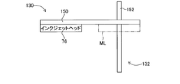
図4乃至図9に示すように、ヘッドスライド機構130は、第1ガイドレール150を有している。第1ガイドレール150においては、上記電磁モータ134の駆動により、インクジェットヘッド76が第1ガイドレール150に沿って移動可能とされている。これにより、インクジェットヘッド76は、吐出位置EL(図9参照)と保守位置ML(図4)との間を移動する。
吐出位置ELとは、第1印刷部72において、インクジェットヘッド76が基台60に載置された基板の上に金属インクを吐出する際の、インクジェットヘッド76の位置をいう。なお、図4乃至図8に示されたインクジェットヘッド76は、吐出位置ELにある。保守位置MLとは、第1印刷部72において、インクジェットヘッド76のメンテナンスが行われる際の、インクジェットヘッド76の位置をいう。なお、図9に示されたインクジェットヘッド76は、保守位置MLにある。
保守スライド機構132は、第2ガイドレール152を有している。第2ガイドレール152は、上記第1ガイドレール150の下方に配設されている。さらに、第2ガイドレール152は、第1ガイドレール150と立体交差した状態で、第1ガイドレール150と直交している。
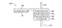
さらに、保守スライド機構132は、インクジェットヘッド76をメンテナンスするための保守ユニット(以下、メンテナンスユニットという)として、ワイピングユニット160、キャッピングユニット162、フラッシングユニット164、及びパージユニット166を有している。なお、以下の説明において、ワイピングユニット160、キャッピングユニット162、フラッシングユニット164、及びパージユニット166を区別せずに総称して説明する場合には、メンテナンスユニット160,162,164,166と表記する。
ワイピングユニット160では、金属インクが吐出するノズルの面(以下、インクジェットヘッド76のノズル面という)をウエス等のワイパー(図示省略)で拭き取るメンテナンス(つまり、ワイピングのメンテナンス)が行われる。キャッピングユニット162では、インクジェットヘッド76のノズル面を蓋で覆うことによって、金属インクの乾燥を防ぐメンテナンス(つまり、キャッピングのメンテナンス)が行われる。フラッシングユニット164では、例えば、乾燥によって金属インクの吐出が不安定になったときに、インクジェットヘッド76のノズルから金属インクを吐出させるメンテナンス(つまり、金属インクの捨て打ちであって、フラッシングのメンテナンス)が行われる。パージユニット166では、例えば、乾燥によって金属インクの吐出が不可能になったときに、インクジェットヘッド76の内圧を通常時よりも上昇させることによって、インクジェットヘッド76のノズルから金属インクを強制的に吐出させるメンテナンス(つまり、パージのメンテナンス)が行われる。なお、これらのメンテナンスを行うための構成は、公知技術のため、その詳細な説明は省略する。
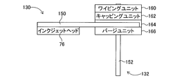
メンテナンスユニット160,162,164,166は、第2ガイドレール152において隣り合った状態で連ねて設けられており、上記電磁モータ136の駆動により、第2ガイドレール152に沿って移動可能とされている。これにより、メンテナンスユニット160,162,164,166は、保守位置MLに移動することが可能である。図5では、ワイピングユニット160が、保守位置MLに位置している。図6では、キャッピングユニット162が、保守位置MLに位置している。図7では、フラッシングユニット164が、保守位置MLに位置している。図8では、パージユニット166が、保守位置MLに位置している。
なお、保守位置MLにおいては、メンテナンスユニット160,162,164,166は、インクジェットヘッド76の下方に位置する。
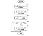
次に、第1印刷部72におけるヘッドスライド機構130と保守スライド機構132の各作動の流れについて、図10に示すフローチャートを参照して説明する。図10のフローチャートで示された制御プログラムは、コントローラ120のROMに記憶されており、インクジェットヘッド76のメンテナンスが行われる際に、コントローラ120のCPUによって実行される。
コントローラ120は、先ず、ステップ(以下、Sと表記する)10において、メンテナンスユニットの移動処理を行う。この処理では、メンテナンスユニット160,162,164,166のいずれか一つのユニットであって、保守対象(以下、メンテナンス対象という)のユニットが保守位置MLに移動される。
S12では、コントローラ120は、インクジェットヘッドの第1移動処理を行う。この処理では、インクジェットヘッド76が吐出位置ELから保守位置MLに移動される。これにより、保守位置MLでは、インクジェットヘッド76が、メンテナンス対象のユニットの上方に位置する。例えば、上記メンテナンス対象のユニットがキャッピングユニット162である場合には、図9に示すように、インクジェットヘッド76がキャッピングユニット162の上方に位置する。
S14では、コントローラ120は、メンテナンス処理を行う。この処理では、保守位置MLにおいて、メンテナンス対象のユニットによるメンテナンスが、インクジェットヘッド76に対して行われる。
S16では、コントローラ120は、キャッピングユニット162が保守位置MLにあるか否かが判別される。キャッピングユニット162が保守位置MLにある場合(S16:YES)には、コントローラ120は、図10のフローチャートで示された制御プログラムを終了する。これにより、保守位置MLでは、キャッピングユニット162によって、インクジェットヘッド76のノズル面が蓋で覆われるメンテナンスが継続される。
これに対して、キャッピングユニット162が保守位置MLにない場合(S16:NO)には、コントローラ120は、S18において、インクジェットヘッドの第2移動処理を行う。この処理では、上記S14のメンテナンス処理におけるメンテナンスが終了した後で、インクジェットヘッド76が保守位置MLから吐出位置ELに移動される。その後、コントローラ120は、図10のフローチャートで示された制御プログラムを終了する。
なお、第2印刷部84のインクジェットヘッド88についても、上記インクジェットヘッド76と同様にして、メンテナンスが行われる。
(D)まとめ
以上より、本実施形態の回路形成装置10では、インクジェットヘッド76の各メンテナンスが保守位置MLで行われる。従って、インクジェットヘッド76のメンテナンスを行う際に必要なインクジェットヘッド76の移動距離は、吐出位置ELから保守位置MLまでの距離で変わらず一定である。そのため、本実施形態の回路形成装置10では、インクジェットヘッド76のメンテナンスを行うメンテナンスユニットの数が増加しても、その増加分のメンテナンスユニットを第2ガイドレール152上に配設すれば、インクジェットヘッド76のメンテナンスを行う際に必要なインクジェットヘッド76の移動距離を一定にすることが可能である。
以上より、本実施形態の回路形成装置10では、インクジェットヘッド76の各メンテナンスが保守位置MLで行われる。従って、インクジェットヘッド76のメンテナンスを行う際に必要なインクジェットヘッド76の移動距離は、吐出位置ELから保守位置MLまでの距離で変わらず一定である。そのため、本実施形態の回路形成装置10では、インクジェットヘッド76のメンテナンスを行うメンテナンスユニットの数が増加しても、その増加分のメンテナンスユニットを第2ガイドレール152上に配設すれば、インクジェットヘッド76のメンテナンスを行う際に必要なインクジェットヘッド76の移動距離を一定にすることが可能である。
この点は、第2印刷部84のインクジェットヘッド88についても、同様である。
ちなみに、本実施形態において、回路形成装置10は、本開示のインクジェット印刷装置の一例である。制御装置26は、本開示の制御部の一例である。第1ガイドレール150は、本開示の第1ガイドの一例である。第2ガイドレール152は、本開示の第2ガイドの一例である。ワイピングユニット160、キャッピングユニット162、フラッシングユニット164、及びパージユニット166の各メンテナンスユニットは、本開示の複数の保守ユニットの一例である。
(E)変更例
なお、本開示は、上記実施形態に限定されるものでなく、その趣旨を逸脱しない範囲で様々な変更が可能である。
なお、本開示は、上記実施形態に限定されるものでなく、その趣旨を逸脱しない範囲で様々な変更が可能である。
以下では、上記実施形態の変更例を説明するが、上記実施形態と実質的に共通する部分には同一の符号を付することによって、詳しい説明を省略する。また、インクジェットヘッド76が2つある場合には、その符号の76に英文字のA又はBを添付することによって、2つのインクジェットヘッド76を区別する。第1ガイドレール150が2つある場合には、その符号の150に英文字のA又はBを添付することによって、2つの第1ガイドレール150を区別する。キャッピングユニット162が2つある場合には、その符号の162に英文字のA又はBを添付することによって、2つのキャッピングユニット162を区別する。吐出位置ELが2つある場合には、その符号のELに数字の1又は2を添付することによって、2つの吐出位置ELを区別する。保守位置MLが2つある場合には、その符号のMLに数字の1又は2を添付することによって、2つの保守位置MLを区別する。
先ず、本開示は、インクジェットヘッド76の複数が一体となって第1ガイドレール150に沿って移動可能とされる場合でも、適用することが可能である。但し、そのような場合には、インクジェットヘッド76の個数分のキャッピングユニット162が、第2ガイドレール152に配設される。
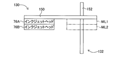
そのような場合の具体例としては、例えば、図11乃至図13に示す第1変更例がある。第1変更例では、インクジェットヘッド76A及びインクジェットヘッド76Bが連結されている。これにより、インクジェットヘッド76A及びインクジェットヘッド76Bは、一体となって、第1ガイドレール150に沿って移動可能である。よって、第1変更例では、インクジェットヘッド76Aが吐出位置EL1(図13参照)にあると、インクジェットヘッド76Bが吐出位置EL2(図13参照)にある。
従って、インクジェットヘッド76Aが保守位置ML1でキャッピングのメンテナンスを受けているときは、保守位置ML2にあるインクジェットヘッド76Bもキャッピングのメンテナンスを受けていなければ、インクジェットヘッド76Bにおいて金属インクが乾燥する虞がある。同様にして、インクジェットヘッド76Bが保守位置ML2でキャッピングのメンテナンスを受けているときは、保守位置ML1にあるインクジェットヘッド76Aもキャッピングのメンテナンスを受けていなければ、インクジェットヘッド76Aにおいて金属インクが乾燥する虞がある。
そこで、第1変更例では、図12に示すように、キャッピングユニット162A及びキャッピングユニット162Bが、第2ガイドレール152において隣り合った状態で連ねて設けられている。そのため、上記S10において、コントローラ120がキャッピングユニット162Aを保守位置ML1に移動させると、キャッピングユニット162Bが保守位置ML2に移動する。あるいは、上記S10において、コントローラ120がキャッピングユニット162Bを保守位置ML2に移動させると、キャッピングユニット162Aが保守位置ML1に移動する。これにより、第1変更例では、図13に示すように、インクジェットヘッド76Aがキャッピングユニット162Aでメンテナンスを受けると同時に、インクジェットヘッド76Bがキャッピングユニット162Bでメンテナンスを受けることが可能である。
なお、図12では、ワイピングユニット160が保守位置ML1にあり、キャッピングユニット162Aが保守位置ML2にある。
また、本開示は、インクジェットヘッド76の複数が個別に第1ガイドレール150に沿って移動可能とされる場合でも、適用することが可能である。但し、そのような場合には、インクジェットヘッド76の個数分の第1ガイドレール150が互いに並んだ状態で設けられ、インクジェットヘッド76の個数分のキャッピングユニット162が、第2ガイドレール152に配設される。
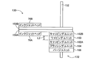
そのような場合の具体例としては、例えば、図14乃至図16に示す第2変更例がある。第2変更例では、インクジェットヘッド76Aが第1ガイドレール150Aに沿って移動可能とされ、インクジェットヘッド76Bが第1ガイドレール150Bに沿って移動可能とされる。そのような第2変更例では、インクジェットヘッド76Aが吐出位置EL1(図16参照)又は保守位置ML1(図14参照)にあっても、インクジェットヘッド76Bは、吐出位置EL2(図16参照)又は保守位置ML2(図14参照)に移動することが可能である。また、インクジェットヘッド76Bが吐出位置EL2(図16参照)又は保守位置ML2(図14参照)にあっても、インクジェットヘッド76Aは、吐出位置EL1(図16参照)又は保守位置ML1(図14参照)に移動することが可能である。つまり、インクジェットヘッド76Aとインクジェットヘッド76Bは個別に移動することが可能である。
また、第1ガイドレール150A及び第1ガイドレール150Bが隣り合った状態(つまり、並んだ状態)で設けられており、インクジェットヘッド76Aの移動とインクジェットヘッド76Bの移動が並行して行われる。従って、保守位置ML1と保守位置ML2の間隔L1(図14参照)は、吐出位置EL1と吐出位置EL2の間隔でもあり、インクジェットヘッド76Aとインクジェットヘッド76Bの間隔でもある。
もっとも、インクジェットヘッド76Aとインクジェットヘッド76Bが個別に移動することが可能な場合でも、例えば、インクジェットヘッド76Aが保守位置ML1でキャッピングのメンテナンスを受けている際に、インクジェットヘッド76Bが保守位置ML2でキャッピングのメンテナンスを受けたいときがある。同様にして、インクジェットヘッド76Bが保守位置ML2でキャッピングのメンテナンスを受けている際に、インクジェットヘッド76Aが保守位置ML1でキャッピングのメンテナンスを受けたいときがある。
そこで、第2変更例では、図15に示すように、キャッピングユニット162A及びキャッピングユニット162Bが、第2ガイドレール152においてワイピングユニット160を介して連ねて設けられ、さらに、保守位置ML1と保守位置ML2との間隔L1(図14参照)と同一の距離L2を置いて設けられる。そのため、上記S10において、コントローラ120がキャッピングユニット162Aを保守位置ML1に移動させると、キャッピングユニット162Bが保守位置ML2に移動する。あるいは、上記S10において、コントローラ120がキャッピングユニット162Bを保守位置ML2に移動させると、キャッピングユニット162Aが保守位置ML1に移動する。これにより、第2変更例では、図16に示すように、インクジェットヘッド76Aがキャッピングユニット162Aでメンテナンスを受けているときに、インクジェットヘッド76Bがキャッピングユニット162Bでメンテナンスを受けることが可能である。
なお、第2変更例において、インクジェットヘッド76A又はインクジェットヘッド76Bのメンテナンスが行われる場合(但し、インクジェットヘッド76A及びインクジェットヘッド76Bに対してキャッピングのメンテナンスが同時に行われる場合を除く)には、コントローラ120は、上記S10と上記S12において、以下の処理を行う。
例えば、メンテナンス対象がインクジェットヘッド76Aである場合には、コントローラ120は、上記S10において、メンテナンスユニット160,162A,162B,164,166のいずれか一つのユニットであって、メンテナンス対象のユニットを保守位置ML1に移動させる。なお、インクジェットヘッド76Aに対して行われるメンテナンスがキャッピングであるときは、コントローラ120は、キャッピングユニット162A又はキャッピングユニット162Bを保守位置ML1に移動させる。図15では、キャッピングユニット162Bが保守位置ML1にある。続いて、コントローラ120は、上記S12において、メンテナンス対象であるインクジェットヘッド76Aを保守位置ML1に移動させる。
このようにして、インクジェットヘッド76Aのメンテナンスが保守位置ML1において行われる(S14)。この点は、インクジェットヘッド76Bのメンテナンスが保守位置ML2において行われる場合でも、同様である。
また、本開示は、上記第2変更例とは異なり、インクジェットヘッド76の個数分のキャッピングユニット162が、第2ガイドレール152に配設されるのではなく、複数のインクジェットヘッド76が第1ガイドレール150に沿って移動可能とされる位置に配設される場合でも、適用することが可能である。
そのような場合の具体例としては、例えば、図17及び図18に示す第3変更例がある。以下では、第3変更例について、上記第2変更例と異なる点を説明する。第3変更例では、キャッピングユニット162Aは、インクジェットヘッド76Aが第1ガイドレール150Aに沿って移動可能とされる位置であって、保守位置ML1とは異なる位置に配設される。また、キャッピングユニット162Bは、インクジェットヘッド76Bが第1ガイドレール150Bに沿って移動可能とされる位置であって、保守位置ML2とは異なる位置に配設される。さらに、第2ガイドレール152においては、メンテナンスユニットのうち、キャッピングユニット162A及びキャッピングユニット162Bを除く、ワイピングユニット160、フラッシングユニット164、及びパージユニット166が、隣り合った状態で連ねて設けられる。
第3変更例において、キャッピングのメンテナンスがインクジェットヘッド76A及びインクジェットヘッド76Bに対して同時に行われる場合には、コントローラ120は、上記S10の処理を行うことなく、上記S12の処理を行う。コントローラ120は、上記S12において、インクジェットヘッド76Aをキャッピングユニット162A(の上方)に移動させ、さらに、インクジェットヘッド76Bをキャッピングユニット162B(の上方)に移動させる。これにより、第3変更例では、インクジェットヘッド76Aがキャッピングユニット162Aでメンテナンスを受けているときに、インクジェットヘッド76Bがキャッピングユニット162Bでメンテナンスを受けることが可能である。
なお、図18では、キャッピングユニット162A(の上方)にインクジェットヘッド76Aが移動しており、また、保守位置ML2にあるワイピングユニット160(の上方)にインクジェットヘッド76Bが移動している。つまり、インクジェットヘッド76Aがキャッピングユニット162Aでキャッピングのメンテナンスを受けると同時に、インクジェットヘッド76Bがワイピングユニット160でワイピングのメンテナンスを受ける。
従って、第3変更例では、インクジェットヘッド76Aがキャッピングユニット162Aのメンテナンスを受けているときに、インクジェットヘッド76Bは、保守位置ML2において、ワイピングユニット160、フラッシングユニット164、又はパージユニット166のメンテナンスを受けることが可能である。同様にして、インクジェットヘッド76Bがキャッピングユニット162Bのメンテナンスを受けているときに、インクジェットヘッド76Aは、保守位置ML1において、ワイピングユニット160、フラッシングユニット164、又はパージユニット166のメンテナンスを受けることが可能である。
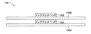
なお、第3変更例は、図19に示す構成に対しても適用することが可能である。図19に示す構成では、第1ガイドレール150A及び第1ガイドレール150Bが離間して並んだ状態で設けられることによって、インクジェットヘッド76Aとインクジェットヘッド76Bとが向かい合うように配置される。
また、第3変更例は、図20に示す構成に対しても適用することが可能である。図20に示す構成では、第1ガイドレール150A及び第1ガイドレール150Bが離間して並んだ状態で設けられることによって、インクジェットヘッド76A及びインクジェットヘッド76Bが第1ガイドレール150A及び第1ガイドレール150Bに対して同一方向に配置される。
また、上述した第1変更例、第2変更例、及び3変更例では、第1印刷部72のインクジェットヘッド76について、本開示を適用しているが、第2印刷部84のインクジェットヘッド88についても、同様にして、本開示を適用することが可能である。
また、第2ガイドレール152は、直線状のものに限定されず、例えば、環状のものであってもよい。この点は、上述した第1変更例、第2変更例、及び3変更例においても、同様である。
また、第1ガイドレール150と第2ガイドレール152は、直角以外の角度で立体交差した状態にあってもよい。この点は、上述した第1変更例、第2変更例、及び3変更例においても、同様である。
また、第2ガイドレール152には、少なくとも2つ以上のメンテナンスユニットが設けられていればよい。さらに、メンテナンスユニットは、ワイピング、キャッピング、フラッシング、及びパージ以外のメンテナンスを行うものでもよい。これらの点は、上述した第1変更例、第2変更例、及び3変更例においても、同様である。
10 回路形成装置
26 制御装置
76 インクジェットヘッド
88 インクジェットヘッド
150 第1ガイドレール
152 第2ガイドレール
160 ワイピングユニット
162 キャッピングユニット
164 フラッシングユニット
166 パージユニット
EL 吐出位置
ML 保守位置
26 制御装置
76 インクジェットヘッド
88 インクジェットヘッド
150 第1ガイドレール
152 第2ガイドレール
160 ワイピングユニット
162 キャッピングユニット
164 フラッシングユニット
166 パージユニット
EL 吐出位置
ML 保守位置
Claims (4)
- 3次元積層造形で使用される樹脂又はインクを吐出する吐出位置と保守が行われる保守位置との間を第1ガイドに沿って移動可能に設けられたインクジェットヘッドと、
前記第1ガイドと立体交差する第2ガイドに沿って移動可能であり、前記インクジェットヘッドの保守を行う複数の保守ユニットと、
前記複数の保守ユニットのいずれか一つの保守ユニットであって、前記保守の対象である前記保守ユニットを、前記保守位置に移動させる制御部とを備えるインクジェット印刷装置。 - 前記インクジェットヘッドを備えた前記第1ガイドが複数並んだ状態で設けられ、
前記制御部は、前記保守の対象である前記保守ユニットを、前記複数のインクジェットヘッドのうち前記保守の対象であるインクジェットヘッドの前記保守位置に移動させる請求項1に記載のインクジェット印刷装置。 - 前記保守位置とは異なる位置であって、前記複数のインクジェットヘッドの各々が互いの前記第1ガイドに沿って移動可能な位置毎に設けられ、前記インクジェットヘッドを覆うことにより前記インクジェットヘッドを保守するキャッピングユニットを複数備え、
前記制御部は、前記複数のインクジェットの全部又は一部を、前記複数のキャッピングユニットの全部又は一部に移動させる請求項2に記載のインクジェット印刷装置。 - 前記制御部は、前記保守に先立ち、前記保守の対象である前記保守ユニットを前記保守位置に移動させる請求項1乃至請求項3のいずれか一つに記載のインクジェット印刷装置。
Priority Applications (2)
| Application Number | Priority Date | Filing Date | Title |
|---|---|---|---|
| PCT/JP2018/005383 WO2019159307A1 (ja) | 2018-02-16 | 2018-02-16 | インクジェット印刷装置 |
| JP2019571902A JP6871435B2 (ja) | 2018-02-16 | 2018-02-16 | インクジェット印刷装置 |
Applications Claiming Priority (1)
| Application Number | Priority Date | Filing Date | Title |
|---|---|---|---|
| PCT/JP2018/005383 WO2019159307A1 (ja) | 2018-02-16 | 2018-02-16 | インクジェット印刷装置 |
Publications (1)
| Publication Number | Publication Date |
|---|---|
| WO2019159307A1 true WO2019159307A1 (ja) | 2019-08-22 |
Family
ID=67619219
Family Applications (1)
| Application Number | Title | Priority Date | Filing Date |
|---|---|---|---|
| PCT/JP2018/005383 Ceased WO2019159307A1 (ja) | 2018-02-16 | 2018-02-16 | インクジェット印刷装置 |
Country Status (2)
| Country | Link |
|---|---|
| JP (1) | JP6871435B2 (ja) |
| WO (1) | WO2019159307A1 (ja) |
Cited By (1)
| Publication number | Priority date | Publication date | Assignee | Title |
|---|---|---|---|---|
| JP2022019121A (ja) * | 2020-07-17 | 2022-01-27 | 株式会社Fuji | キャッピング装置及びそれを備える3次元造形物製造装置 |
Families Citing this family (1)
| Publication number | Priority date | Publication date | Assignee | Title |
|---|---|---|---|---|
| JP2023160025A (ja) * | 2022-04-21 | 2023-11-02 | 株式会社Fuji | メンテナンス方法、および回路作製装置 |
Citations (5)
| Publication number | Priority date | Publication date | Assignee | Title |
|---|---|---|---|---|
| JP2006341543A (ja) * | 2005-06-10 | 2006-12-21 | Konica Minolta Holdings Inc | インクジェットプリンタ |
| US20070146415A1 (en) * | 2005-12-28 | 2007-06-28 | Samsung Electronics Co., Ltd. | Inkjet image forming apparatus having a wiping unit |
| JP2008229892A (ja) * | 2007-03-16 | 2008-10-02 | Seiko Epson Corp | ワイピング装置、並びに同ワイピング装置を備えたメンテナンスユニット及び流体噴射装置 |
| JP2012153128A (ja) * | 2011-01-28 | 2012-08-16 | Brother Industries Ltd | 液体噴射装置 |
| JP2016147426A (ja) * | 2015-02-12 | 2016-08-18 | キヤノン株式会社 | 記録装置およびその制御方法 |
Family Cites Families (1)
| Publication number | Priority date | Publication date | Assignee | Title |
|---|---|---|---|---|
| JP2011136270A (ja) * | 2009-12-28 | 2011-07-14 | Seiko Epson Corp | 記録方法 |
-
2018
- 2018-02-16 JP JP2019571902A patent/JP6871435B2/ja active Active
- 2018-02-16 WO PCT/JP2018/005383 patent/WO2019159307A1/ja not_active Ceased
Patent Citations (5)
| Publication number | Priority date | Publication date | Assignee | Title |
|---|---|---|---|---|
| JP2006341543A (ja) * | 2005-06-10 | 2006-12-21 | Konica Minolta Holdings Inc | インクジェットプリンタ |
| US20070146415A1 (en) * | 2005-12-28 | 2007-06-28 | Samsung Electronics Co., Ltd. | Inkjet image forming apparatus having a wiping unit |
| JP2008229892A (ja) * | 2007-03-16 | 2008-10-02 | Seiko Epson Corp | ワイピング装置、並びに同ワイピング装置を備えたメンテナンスユニット及び流体噴射装置 |
| JP2012153128A (ja) * | 2011-01-28 | 2012-08-16 | Brother Industries Ltd | 液体噴射装置 |
| JP2016147426A (ja) * | 2015-02-12 | 2016-08-18 | キヤノン株式会社 | 記録装置およびその制御方法 |
Cited By (2)
| Publication number | Priority date | Publication date | Assignee | Title |
|---|---|---|---|---|
| JP2022019121A (ja) * | 2020-07-17 | 2022-01-27 | 株式会社Fuji | キャッピング装置及びそれを備える3次元造形物製造装置 |
| JP7495836B2 (ja) | 2020-07-17 | 2024-06-05 | 株式会社Fuji | キャッピング装置及びそれを備える3次元造形物製造装置 |
Also Published As
| Publication number | Publication date |
|---|---|
| JPWO2019159307A1 (ja) | 2020-12-03 |
| JP6871435B2 (ja) | 2021-05-12 |
Similar Documents
| Publication | Publication Date | Title |
|---|---|---|
| KR20140108352A (ko) | 액체 토출 장치, 나노임프린트 시스템 및 액체 토출 방법 | |
| WO2011108750A1 (en) | Pattern transfer method and apparatus | |
| CN109315066B (zh) | 电路形成方法 | |
| WO2019058515A1 (ja) | 半硬化層の形成方法及び半硬化層形成装置 | |
| JP6871435B2 (ja) | インクジェット印刷装置 | |
| US8740340B2 (en) | Printing device | |
| WO2017212567A1 (ja) | 回路形成方法 | |
| JP6926078B2 (ja) | 回路形成方法、および回路形成装置 | |
| JP6714109B2 (ja) | 回路形成方法、および回路形成装置 | |
| WO2016189577A1 (ja) | 配線形成方法 | |
| JP7428470B2 (ja) | 回路形成方法 | |
| JP5281989B2 (ja) | パターン転写装置及びパターン形成方法 | |
| JPWO2017006412A1 (ja) | 造形装置および造形方法 | |
| JP6949751B2 (ja) | 3次元積層造形のビア形成方法 | |
| JP6816283B2 (ja) | 配線形成方法、および配線形成装置 | |
| JP6663516B2 (ja) | 回路形成方法、および回路形成装置 | |
| KR102559882B1 (ko) | 액적 토출 방법 및 장치 | |
| JP6818154B2 (ja) | 配線形成方法、および配線形成装置 | |
| JP7495836B2 (ja) | キャッピング装置及びそれを備える3次元造形物製造装置 | |
| WO2016199242A1 (ja) | 回路パターン形成装置 | |
| JP7171941B2 (ja) | 吐出装置 | |
| JP2023131281A (ja) | 電気回路形成方法、および制御プログラム | |
| JP6808050B2 (ja) | 配線形成方法、および配線形成装置 | |
| JP6866198B2 (ja) | 回路形成装置 | |
| WO2017017726A1 (ja) | 3次元造形物造形装置 |
Legal Events
| Date | Code | Title | Description |
|---|---|---|---|
| 121 | Ep: the epo has been informed by wipo that ep was designated in this application |
Ref document number: 18906193 Country of ref document: EP Kind code of ref document: A1 |
|
| ENP | Entry into the national phase |
Ref document number: 2019571902 Country of ref document: JP Kind code of ref document: A |
|
| NENP | Non-entry into the national phase |
Ref country code: DE |
|
| 122 | Ep: pct application non-entry in european phase |
Ref document number: 18906193 Country of ref document: EP Kind code of ref document: A1 |