WO2019159271A1 - 空気調和機 - Google Patents
空気調和機 Download PDFInfo
- Publication number
- WO2019159271A1 WO2019159271A1 PCT/JP2018/005186 JP2018005186W WO2019159271A1 WO 2019159271 A1 WO2019159271 A1 WO 2019159271A1 JP 2018005186 W JP2018005186 W JP 2018005186W WO 2019159271 A1 WO2019159271 A1 WO 2019159271A1
- Authority
- WO
- WIPO (PCT)
- Prior art keywords
- air conditioner
- radiation temperature
- temperature
- air
- detection device
- Prior art date
- Legal status (The legal status is an assumption and is not a legal conclusion. Google has not performed a legal analysis and makes no representation as to the accuracy of the status listed.)
- Ceased
Links
Images





Classifications
-
- F—MECHANICAL ENGINEERING; LIGHTING; HEATING; WEAPONS; BLASTING
- F24—HEATING; RANGES; VENTILATING
- F24F—AIR-CONDITIONING; AIR-HUMIDIFICATION; VENTILATION; USE OF AIR CURRENTS FOR SCREENING
- F24F11/00—Control or safety arrangements
- F24F11/62—Control or safety arrangements characterised by the type of control or by internal processing, e.g. using fuzzy logic, adaptive control or estimation of values
-
- F—MECHANICAL ENGINEERING; LIGHTING; HEATING; WEAPONS; BLASTING
- F24—HEATING; RANGES; VENTILATING
- F24F—AIR-CONDITIONING; AIR-HUMIDIFICATION; VENTILATION; USE OF AIR CURRENTS FOR SCREENING
- F24F11/00—Control or safety arrangements
- F24F11/70—Control systems characterised by their outputs; Constructional details thereof
- F24F11/72—Control systems characterised by their outputs; Constructional details thereof for controlling the supply of treated air, e.g. its pressure
- F24F11/79—Control systems characterised by their outputs; Constructional details thereof for controlling the supply of treated air, e.g. its pressure for controlling the direction of the supplied air
-
- F—MECHANICAL ENGINEERING; LIGHTING; HEATING; WEAPONS; BLASTING
- F24—HEATING; RANGES; VENTILATING
- F24F—AIR-CONDITIONING; AIR-HUMIDIFICATION; VENTILATION; USE OF AIR CURRENTS FOR SCREENING
- F24F11/00—Control or safety arrangements
- F24F11/88—Electrical aspects, e.g. circuits
-
- F—MECHANICAL ENGINEERING; LIGHTING; HEATING; WEAPONS; BLASTING
- F24—HEATING; RANGES; VENTILATING
- F24F—AIR-CONDITIONING; AIR-HUMIDIFICATION; VENTILATION; USE OF AIR CURRENTS FOR SCREENING
- F24F11/00—Control or safety arrangements
- F24F11/89—Arrangement or mounting of control or safety devices
Definitions
- the present invention relates to an air conditioner, and more particularly, to an indoor unit of an air conditioner having a plurality of air outlets and a louver for controlling the air direction at each air outlet.
- a human sensor As an indoor unit of an air conditioner, in order to improve energy saving and comfort, a human sensor is installed, and the presence / absence of a person in the air-conditioned room is determined. Some control the wind direction to change automatically. In order to perform these controls more effectively, it is necessary to estimate the temperature felt by a person.
- the human detection sensor which detects the presence or absence of the person in an air-conditioning room
- the temperature sensor which detects the temperature of the upper part and the lower part in an air conditioned room
- the louver corresponding to the blowing area where the absence of a person is detected when the absence of a person in each blowing area is detected and the temperature difference between the upper part and the lower part in the air conditioning room is equal to or greater than a predetermined temperature difference. It describes that the wind direction angle of (wind direction change blade) is set downward. Further, it is described that when the human detection sensor detects the presence of a person in each of the blowing areas, the louver wind direction angle corresponding to the blowing area where the presence of the person is detected is set to horizontal blowing. .
- the temperature direction unevenness is improved by changing the louver wind direction angle according to the presence or absence of a person. In order to improve comfort, it is possible to suppress the discomfort caused by the drafts of people present in each blowing area.
- the floor surface temperature is calculated, and when this floor surface temperature is separated from the set room temperature by a predetermined value or more, It describes that the set rotational speed of the indoor fan is corrected so that the surface temperature approaches the set room temperature.
- correcting the set room temperature or changing the angle of the wind direction louver also eliminates overcooling during cooling. Has been.
- the radiation temperature sensor is used to estimate the temperature felt by a person, and the radiation temperature emitted from the floor or desk is measured. If there is a person in the room, the radiation temperature sensor will also measure the body temperature of the person, so the more people in the detection area, the more difficult it is to measure the radiation temperature near the floor surface more accurately. There is.
- the radiation temperature sensor measures not only the floor surface temperature but also the temperature of the person, so the radiation temperature sensor is more than the actual floor surface temperature. A high temperature value is output as a detection value. For this reason, there is a problem that control for reducing the excessive cooling cannot be started even if the actual floor surface temperature is low and the cooling is excessive.
- An object of the present invention is to provide an air conditioner that can start over-cooling mitigation control at an appropriate timing even when there are many people in the detection area of the radiation temperature sensor when the floor surface temperature becomes low. There is to get a chance.
- the present invention provides a predetermined condition in an air conditioner including a plurality of air outlets and a plurality of louvers that are provided in the air outlets and configured to be capable of adjusting the air outlet direction.
- a control device that executes overcooling reduction control and a human detection device that detects a person in the room, and the control device detects the overcooling reduction control when the human detection device detects a person.
- the start condition is corrected so as to make it easier to start the over-cooling reduction control.
- the air conditioning that can start the overcooling mitigation control at an appropriate timing there is an effect that can get a machine.
- Example 1 of the air conditioner of this invention It is a longitudinal cross-sectional view of the indoor unit shown in FIG.
- FIG. 3 is a cross-sectional view of one main part of the air outlet shown in FIGS. 1 and 2. It is explanatory drawing explaining the indoor floor surface temperature which a radiation temperature sensor detects. It is explanatory drawing explaining the indoor floor surface temperature which a radiation temperature sensor detects. It is explanatory drawing explaining the indoor floor surface temperature which a radiation temperature sensor detects. It is explanatory drawing explaining the indoor floor surface temperature which a radiation temperature sensor detects. It is a flowchart explaining control of Example 1 of the air conditioner of this invention. It is a flowchart explaining control of Example 2 of the air conditioner of this invention. It is a flowchart explaining control of Example 3 of the air conditioner of this invention. It is a flowchart explaining control of Example 4 of the air conditioner of this invention.
- FIG. 1 is a perspective view illustrating the air conditioner of the first embodiment.
- an air conditioner (hereinafter also referred to as an indoor unit) 1 is connected to an outdoor unit (not shown) by a refrigerant pipe to form a refrigerant circuit, and a refrigerant is circulated to constitute a refrigeration cycle.
- This indoor unit 1 is a so-called ceiling cassette type, and includes a housing 2 embedded in an indoor ceiling and the like, a decorative panel 3 provided so as to close a lower surface opening of the housing 2, and the like.
- a suction port 4 which is provided in the center and sucks room air and four air outlets 5 which are provided so as to surround the suction port 4.
- the suction port 4 is provided with a suction grill 6, and each of the outlets 5 is rotatably provided with a louver 7 for adjusting the direction of air blown from the outlet 5.
- the louver 7 shown in FIG. 1 shows a state where the indoor unit 1 is stopped and fully closed, that is, a state where the louver angle is a fully closed angle (0 degree).
- the fully closed state includes not only a state in which the air outlet 5 is completely closed, but also a state in which the opening area is minimized so that the louver substantially closes the air outlet.
- a radiation temperature sensor (radiation temperature detection device) 18 and a human sensor (human detection device) 19 are provided at the corner of the decorative panel 3.
- the radiation temperature sensor 18 detects the radiation temperature from the floor surface in the room (air-conditioned room) in which the indoor unit 1 is installed (hereinafter also referred to as the room) and calculates the floor temperature.
- the human sensor 19 is used to detect the presence and distribution of people in the room, and the amount of activity of people in each area of the room.
- the human sensor 19 includes a plurality of infrared sensors and the like, and irradiates infrared rays in a plurality of directions in the room (for example, areas in four directions corresponding to the blowing direction of the indoor unit 1). This is to detect the presence of people in the area and the amount of activity of the people in each area.
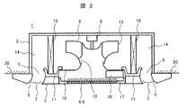
- FIG. 2 is a longitudinal sectional view of the indoor unit 1 shown in FIG.
- a motor 8 and a centrifugal fan 9 connected to the rotating shaft of the motor 8 are installed in the center of the housing 2.
- the motor 8 is fixed to the center of the top plate of the housing 2.
- a square-shaped heat exchanger 10 is installed around the centrifugal fan 9 so as to surround the centrifugal fan 9 in a plan view.
- the heat exchanger 10 is a cross fin type fin-and-tube heat exchanger.
- a drain pan 11 for receiving dew condensation water generated in the heat exchanger 10 is installed at the lower part of the heat exchanger 10.
- a heat insulating material made of styrene foam is generally used, a water receiving groove is formed along the lower end of the heat exchanger 10, and the lower end portion of the heat exchanger 10 enters the water receiving groove.
- the air outlet 5 is formed of a heat insulating material that is integral with or separate from the heat insulating material that constitutes the drain pan 11.
- the 20 is an indoor ceiling, and the indoor unit 1 is installed with the casing 2 embedded in the ceiling 20.
- the decorative panel 3 is formed in a square shape that is slightly larger than the casing 2, is disposed along the ceiling 20 so as to cover the lower surface of the casing 2, and is exposed to the indoor space.
- the louver 7 provided at the air outlet 5 of the decorative panel 3 is in a fully closed position (louver angle is 0 degree) in FIG. 2, and shows a state in which the operation of the indoor unit 1 is stopped. .
- the louver 7 is rotated so as to open the air outlet 5, and is fixed at a predetermined angle set by the user from a remote controller (not shown), such as bottom blowing or side blowing. Is done.
- a remote controller not shown
- the louver 7 performs the auto swing operation in the range from the minimum angle to the maximum angle.
- louver 7 performs the auto swing operation in the range from the minimum angle to the maximum angle, so that the conditioned air is vertical from the direction close to the horizontal according to the movement of the louver 7. It is blown out to the direction near.
- 15 is a bell mouth that is arranged below the centrifugal fan 9 and has an opening that rises toward the suction portion 12 of the centrifugal fan 9 while gradually reducing the diameter at the center.
- the bell mouth 15 is for guiding the air sucked from the suction port 4 to the centrifugal fan 9.
- Reference numeral 17 denotes a suction filter installed on the upper side of the suction grill 6.
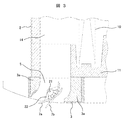
- FIG. 3 is an enlarged cross-sectional view of a main part in the vicinity of one outlet shown in FIGS. 1 and 2 show the louver in a fully closed state, but FIG. 3 shows the minimum angle (first angle) and the maximum angle (second angle) of the louver during operation of the indoor unit. .
- FIG. 3 shows the operating range of the louver 7 when the indoor unit 1 is in operation
- the louver 7a indicated by a solid line is the minimum angle of the louver 7 that can be set by the user with a remote controller (not shown).
- a louver 7b that indicates (first angle) and is indicated by a one-dot chain line indicates the maximum angle (second angle) of the louver 7 that can be set by the user with the remote controller.
- the louver 7 When the louver 7 is set to the position 7a of the minimum angle (first angle), the conditioned air blown from the blowout port 5 is a side blowing operation in which it is blown out in a substantially horizontal direction. On the other hand, when the louver 7 is set to the position 7b of the maximum angle (second angle), the conditioned air blown from the blowout port 5 is in a downward blowing operation in which it is blown out in a substantially vertical direction.
- the minimum angle (first angle) is, for example, 28 degrees
- the maximum angle (second angle) For example, 64 degrees.
- the minimum angle (first angle) may be arbitrarily set within a range of about 27 to 30 degrees, for example.
- the maximum angle (second angle) may be arbitrarily set within a range of about 60 to 70 degrees, for example.
- the angle of the louver 7 during the operation of the indoor unit 1 can be set from the remote controller to the aforementioned minimum angle and maximum angle, as well as from the remote controller in several steps in steps of several degrees between the aforementioned minimum angle and maximum angle. It is configured to be configurable. For example, the minimum angle is the first step and the maximum angle is the seventh step, and the five steps (second to sixth steps) can be set between the first and seventh steps. . Note that the angle of the louver 7 is not limited to seven steps, and may be larger or smaller. Moreover, you may comprise so that a louver angle can be set to arbitrary angles without a step.
- the louver 7 When the operation of the louver 7 is set to auto swing from the remote controller, the louver 7 has an angle at the start of auto swing setting, for example, the first angle, which is the minimum angle, and the second, third,... The reciprocating operation is repeated until the 7th stage is increased, and then, in the reverse direction, the 6th stage, the 5th stage,...
- the auto swing is not limited to the reciprocating operation between the first stage to the seventh stage, and may be configured to perform the reciprocating operation of the third stage to the seventh stage, for example.
- the louver angle can be configured to change smoothly and continuously.
- reference numeral 3 a denotes a heat insulating material such as a polystyrene foam that forms the air outlet 5.
- the louver 7 is formed in an elongated plate shape or wing shape extending from one end to the other end in the longitudinal direction of the air outlet 5, and the louver 7 extends in the longitudinal direction. It is fixed to the central shaft 21 via an attachment member 22.
- the central shaft 18 is rotatably supported by support members (not shown) disposed at both ends thereof, and its rotation is controlled by a stepping motor or the like.
- the radiation temperature sensor 18 shown in FIG. 1 is used to measure the radiation temperature emitted from the floor, desk, etc., and the measured radiation temperature is higher than the set temperature of the indoor unit 1 (the set temperature of the room set from the remote controller or the like).
- the overcool reduction control is performed when the temperature is small (or the temperature difference between them is equal to or higher than a predetermined temperature).
- control is performed so as not to overcool by adding a correction value to the set temperature of the indoor unit 1 or changing the louver angle or the air volume.
- the over-cooling reduction control is performed.
- a correction value for example, 2 ° C.
- the louver angle is reduced to blow out horizontally, or the air volume is reduced to control overcooling.
- FIG. 4 is an explanatory diagram for explaining the floor temperature in the room (inside the room) detected by the radiation temperature sensor 18.
- the radiation temperature A detected by the radiation temperature sensor 18 is the floor surface temperature B, and when the detected radiation temperature A becomes lower than the set temperature of the indoor unit 1 (or measurement). If the temperature of the radiated temperature and the set temperature is greater than the predetermined temperature), it is determined that the indoor space to be air-conditioned is too cold, and the overcooling reduction control is started.
- the floor surface temperature B is 24 ° C.
- the radiation temperature A detected by the radiation temperature sensor 18 is approximately 24 ° C.
- the set temperature of the indoor unit 1 is 26 ° C., for example, the radiation temperature A detected by the radiation temperature sensor 18 is lower than the set temperature, so it is determined that the indoor unit 1 is too cold, and the indoor unit 1 is too cold.
- Start mitigation control Specifically, according to the magnitude of the temperature difference between the radiation temperature and the set temperature, the set temperature of the indoor unit 1 is corrected (for example, a correction value of 2 ° C. if the temperature difference is 2 ° C.). And the angle and air volume of the louver 7 are changed.
- C is the air temperature near the ceiling, and this air temperature is detected by a suction temperature sensor (not shown) provided in the indoor unit 1.
- the detected air temperature C is compared with the set temperature, and the air conditioner is controlled so that the air temperature C approaches the set temperature.
- D is the temperature of the blown air blown from the blowout port 5 of the indoor unit 1, and this blown air temperature D is, for example, 10 ° C.
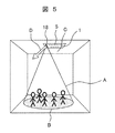
- FIG. 5 is also an explanatory diagram for explaining the indoor floor surface temperature detected by the radiation temperature sensor 18, but the example shown in FIG. 5 is for a case where there are many people in the detection area detected by the radiation temperature sensor 18. It is a figure explaining a subject.
- the radiation temperature A detected by the radiation temperature sensor is detected to be higher than the actual floor surface temperature B, and the radiation temperature sensor 18 detects the floor.
- the surface temperature B cannot be measured accurately. For this reason, even when the floor surface temperature B is too low and the temperature is too cold, since the temperature difference between the set temperature and the radiation temperature A detected by the radiation temperature sensor 18 is small, the overcooling mitigation control is started. There is a problem that can not be done.
- the radiation temperature sensor 18 detects more people than the floor surface temperature B, and the radiation temperature sensor The detected value at 18 is 26 ° C., for example. For this reason, since a difference with the set temperature of 26 ° C. does not occur, it cannot be determined that the temperature is too cold, and the indoor unit 1 cannot start the overcooling reduction control.
- FIG. 6 is also an explanatory diagram for explaining the indoor floor surface temperature detected by the radiation temperature sensor 18, but the example shown in FIG. 6 is an embodiment of the present invention that can solve the problem described with reference to FIG. It is a figure explaining control of the air conditioner in 1 (indoor unit 1).
- the radiation temperature sensor 18 When there are many people in the detection area detected by the radiation temperature sensor 18, even when the floor surface temperature B is 24 ° C., the radiation temperature sensor 18 is higher than the floor surface temperature B as described in FIG. Many people in the detection area will be detected. For this reason, the radiation temperature A detected by the radiation temperature sensor 18 is 26 ° C., for example.
- the over-cooling reduction control can be started.
- FIG. 7 is a flowchart illustrating the control of the air conditioner according to the first embodiment.
- the control flow according to the first embodiment will be described with reference to FIG.
- the cooling operation of the air conditioner (indoor unit 1) is started in step A1
- the excessive cooling reduction control is enabled (ON) in step A2
- the amount of human activity is detected in step A3.
- the human sensor (person detection device) 19 shown in FIG. the human sensor 19 shown in FIG.
- the radiation temperature of the floor is also detected using the radiation temperature sensor (radiation temperature detection device) 18 shown in FIG.
- the human sensor 19 is configured to detect not only the presence / absence of a person but also the amount of activity of the person.
- control is also performed using the detected amount of activity of the person.
- the process proceeds to step A4, and the radiation temperature is changed according to the detected activity amount of the person.
- the correction value ⁇ ( ⁇ > 0) for the radiation temperature detected by the sensor 18 is output, and the process proceeds to step A5.
- the magnitude of the correction value ⁇ is predetermined according to the amount of activity of the person detected by the human sensor 19.
- step A5 the value obtained by subtracting the correction value ⁇ from the radiation temperature A detected by the radiation temperature sensor 18 is compared with the set temperature of the air conditioner (indoor unit 1).
- the value of “A ⁇ ” is large (in the case of No)
- step A6 the process proceeds to step A6 to reduce overcooling.
- Start control In this overcooling mitigation control, the set temperature of the air conditioner is set to a higher temperature, or the wind direction of the louver 7 is changed to the horizontal direction so as to prevent wind from hitting a person. Moreover, it controls so that the blowing air volume of the blowing air which blows off from the said blower outlet 5 is decreased.
- the change amount depends on the difference between the set temperature and the measured radiation temperature A or a value obtained by correcting the measured value of the radiation temperature (A ⁇ ). It may be determined based on a predetermined correction amount.
- the control for reducing the blown air volume is performed, for example, by 1 tap with respect to the current air volume. In other words, if the current setting is the H steep wind setting (the air volume that is larger than the air volume in the steep wind setting), the normal steep wind setting may be changed.
- control is performed so as to change at least one or two of the set temperature, the wind direction of the louver 7 and the blowout air volume, or control to change all of them. You may do it.
- step A7 it is determined whether or not the over-cooling mitigation control end condition, for example, the value of “A ⁇ ” has become larger than the set temperature.
- the process proceeds to step A8, and over-cooling mitigation is performed.
- the changed set temperature, air direction, and air volume are cleared and returned to the original state, and the overcooling reduction control is ended (step A9). After that, it is preferable that the control flow of A3 to A9 shown in FIG. 7 is repeatedly executed.
- the correction value ⁇ is output in accordance with the amount of human activity. Therefore, the correction value ⁇ is subtracted from the radiation temperature A detected by the radiation temperature sensor 18. Thus, it can be accurately determined whether or not it is too cold. As a result, the influence of the person in the room can be eliminated or reduced, so that the overcooling reduction control can be started at an appropriate timing without a time delay.
- FIG. 8 is a flowchart for explaining the control of the air conditioner according to the second embodiment.
- the control flow of the air conditioner according to the second embodiment will be described with reference to FIG.
- the description of the same parts as those of the first embodiment will be omitted, and different parts will be mainly described.
- the configuration of the air conditioner shown in FIGS. 1 to 3 is the same as that described in the first embodiment, and only the control flow shown in FIG. 8 is different. 4 and FIG. 5 are also the same, so the following description will be made with reference to FIGS. 1 to 5 as necessary.
- the radiation temperature sensor 18 when the radiation temperature sensor 18 is provided at a position affected by the blowout air blown from the outlet 5, the radiation temperature measured by the radiation temperature sensor 18 during cooling operation. However, under the influence of the blowing air, a value lower than the actual floor surface temperature B is output.
- a correction value ⁇ determined in advance based on the influence of the blown wind is added to the radiation temperature measured by the radiation temperature sensor 18 and output, and this correction value is added.
- the measured value is compared with the set temperature. In this way, the influence of the blown air is eliminated by correcting the radiation temperature detected by the radiation temperature sensor 18 so that its value becomes higher.
- step B2 When the blowing temperature hits the radiation temperature sensor 18 (in the case of Yes), the process proceeds to step B2, and the correction value ⁇ ( ⁇ > 0) is added to the radiation temperature A detected by the radiation temperature sensor 18 and output. Then, the process proceeds to step A2.
- steps A2 to A9 are executed as in the first embodiment shown in FIG.
- ⁇ in step A5 is greater than 0, and the value of “radiant temperature A + ⁇ ” is compared with the set temperature of the air conditioner.
- the process returns to step A3 and the same operation is repeated, and if the value of “A + ⁇ ” becomes smaller than the set temperature. (In the case of Yes), it transfers to step A6 and implements over-cooling reduction control.
- the following flow is the same as in the case of FIG.
- the correction value ⁇ is added to the radiation temperature A detected by the radiation temperature sensor 18. It can correct
- FIG. 9 is a flowchart for explaining the control of the air conditioner of the third embodiment.
- the control flow of the air conditioner of the third embodiment will be described with reference to FIG.
- the description of the same parts as those of the first embodiment will be omitted, and different parts will be mainly described.
- the configuration of the air conditioner shown in FIGS. 1 to 3 is the same as that of the first embodiment, and only the control flow shown in FIG. 9 is different. 4 and FIG. 5 are also the same, so the following description will be made with reference to FIGS. 1 to 5 as necessary.
- the third embodiment is configured such that after the air conditioner starts the cooling operation and a predetermined time has elapsed, the excessive cooling reduction control is started. That is, if the cooling operation of the air conditioner (indoor unit 1) is started in step A1, and the excessive cooling reduction control is enabled (ON) in step A2, the operation time after the start of operation is measured, and the step In C1, it is determined whether or not a predetermined time has elapsed. If the predetermined time has not elapsed (in the case of No), the process returns to step A2, and if the predetermined time has elapsed (in the case of Yes), it is determined that the cooling operation is in a stable state and the process proceeds to step A3. It is intended to migrate.
- control flow is the same as steps A3 to A9 shown in FIG. 7, description of those steps is omitted.
- the control flow (steps A3 to A9) of the overcooling reduction control is performed after a predetermined time has elapsed after the start of the cooling operation, the temperature of the air-conditioned room (room) is stable. After that, the over-cooling reduction control can be started. Therefore, it is possible to obtain an effect of enabling stable overcooling reduction control.
- FIG. 10 is a flowchart for explaining the control of the air conditioner of the fourth embodiment.
- the control flow of the air conditioner of the fourth embodiment will be described with reference to FIG.
- the description of the same parts as those of the first to third embodiments will be omitted, and different parts will be mainly described.
- the configuration of the air conditioner shown in FIGS. 1 to 3 is the same as that described in the first embodiment, and only the control flow shown in FIG. 10 is different from the first to third embodiments. 4 and FIG. 5 are also the same, so the following description will be made with reference to FIGS. 1 to 5 as necessary.
- Steps B1 and B2 of the second embodiment shown in FIG. 8 are added to the flow of the first embodiment shown in FIG. 7, and the control of the step C1 of the third embodiment shown in FIG. 9 is further added. Is.
- the process proceeds to step B2, and a correction value ⁇ ( ⁇ > 0) for the radiation temperature A detected by the radiation temperature sensor 18 is output, and step A2 Migrate to
- step A1 when the cooling operation is started (step A1), the operation time after the start is measured, and if the overcooling reduction control is enabled (ON) in step A2, the step is performed.
- the process proceeds to C1 to determine whether or not a predetermined time has elapsed. If the predetermined time has not elapsed (in the case of No), the process returns to step A2, and if the predetermined time has elapsed (in the case of Yes), it is determined that the cooling operation is in a stable state. The process is shifted to A3. Since the following control flow is the same as steps A3 to A9 shown in FIG. 8, description of those steps is omitted.
- the influence of the presence of a person and the influence of blowing air on the radiation temperature sensor 18 are eliminated, and the correction by the correction values ⁇ and ⁇ described above is applied to the detected radiation temperature A. (Subtract or add), the floor surface temperature B can be estimated more accurately, and the over-cooling mitigation control can be started for the indoor space where air conditioning is stable. This makes it possible to obtain an effect of starting over-cooling mitigation control at a more appropriate timing.
- each of the embodiments of the air conditioner of the present invention includes a plurality of air outlets, a plurality of louvers that are provided in the air outlets and configured to adjust the air outlet direction, and are determined in advance.
- a control device that performs overcooling reduction control when a predetermined condition is satisfied, and a human sensor (human detection device) that detects a person in the room.
- the control device corrects the predetermined start condition of the overcooling reduction control so that the overcooling reduction control is easily started. That is, when there is a person in the room, a correction for subtracting the correction value ⁇ from the measured radiation temperature A is performed so that the excessive cooling reduction control can be easily started in consideration of the temperature rise caused by the person.
- the overcooling mitigation control is started at an appropriate timing. The effect that can be obtained.
- the temperature is too cold when the measured radiation temperature A or the value obtained by subtracting the correction value ⁇ is smaller than the set temperature of the indoor unit.
- the detected radiation temperature A or a value obtained by subtracting the correction value ⁇ from the detected radiation temperature A is compared with the set temperature of the indoor unit, and when the difference is equal to or higher than a predetermined temperature, the temperature is cooled. You may make it determine with passing.
- 1 air conditioner (indoor unit), 2: housing, 3: decorative panel, 3a: heat insulating material, 4: suction port, 5: air outlet, 6: suction grille, 7: louver, 7a: minimum angle (first 1 angle), 7b: maximum angle (second angle) position, 8: motor, 9: centrifugal fan, 10: heat exchanger, 11: drain pan, 12: suction part, 13: discharge part, 14: wind Road: 15: Bellmouth, 16: Electrical box, 17: Suction filter, 18: Radiation temperature sensor (radiation temperature detection device), 19: Human sensor (human detection device), 20: Ceiling, 21: Central axis, 22: mounting member, A: radiation temperature detected by the radiation temperature sensor, B: floor surface temperature, C: air temperature near the ceiling, D: blowing air temperature, ⁇ , ⁇ : correction values.
Landscapes
- Engineering & Computer Science (AREA)
- Chemical & Material Sciences (AREA)
- Combustion & Propulsion (AREA)
- Mechanical Engineering (AREA)
- General Engineering & Computer Science (AREA)
- Physics & Mathematics (AREA)
- Fuzzy Systems (AREA)
- Mathematical Physics (AREA)
- Signal Processing (AREA)
- Air Conditioning Control Device (AREA)
Abstract
床面温度が低くなった場合、輻射温度センサの検知エリア内に人がたくさん存在する場合であっても、適切なタイミングで冷え過ぎ軽減制御を開始する。このため、本発明は、複数の吹出口と、前記各吹出口に設けられ吹出し方向を調節可能に構成されている複数のルーバを備える空気調和機において、予め定めた所定の条件になると冷え過ぎ軽減制御を実行する制御装置と、室内の人を検知する人検知装置と、を備え、前記制御装置は、前記人検知装置が人を検知すると、前記冷え過ぎ軽減制御の前記所定の開始条件を、冷え過ぎ軽減制御を開始し易くなるように補正する。
Description
本発明は、空気調和機に係り、特に、複数の吹出口を有し、それぞれの吹出口に風向を制御するためのルーバを備える空気調和機の室内機に関する。
空気調和機の室内機としては、省エネ性や快適性を向上させるために、人感センサを搭載し、空調する室内の人の在不在を判定して、その判定結果に応じて、空調能力や風向を自動で変更するように制御するものがある。これらの制御をより効果的に行なうためには、人が感じている温度を推定する必要がある。
室内に居る人が感じている温度を推定する手段としては、室内機に輻射温度センサを搭載して、床面付近の輻射温度を測定することにより推定する技術がある。このような従来技術としては、特許第5310792号公報(特許文献1)や特許第3751516号公報(特許文献2)に記載されているものがある。
上記特許文献1のものでは、空調室内における人の存在の有無を検知する人検知センサと、空調室内における上部及び下部の温度を検知する温度センサを設け、冷房運転において、前記人検知センサにより前記各吹出エリアにおける人の非存在を検知し、かつ、前記空調室内における上部と下部との温度差が所定温度差以上である場合には、人の非存在が検知された吹出エリアに対応するルーバ(風向変更羽根)の風向角度を下向きに設定することが記載されている。また、前記人検知センサが前記各吹出エリアにおける人の存在を検知した場合には、人の存在が検知された吹出エリアに対応するルーバの風向角度を水平吹きに設定することが記載されている。
このように、空調室内の上部(天井部)と下部(床面部)に温度差がある場合、人の存在の有無に応じて、ルーバの風向角度を変更することで、温度ムラを改善しつつ、各吹出エリアに存在する人のドラフトによる不快感を抑え、快適性の向上を図っている。
上記特許文献2のものでは、床面からの輻射温度を検出する輻射温度検出手段を設けて床面温度を算出し、この床面温度が設定室温より所定値以上離れている場合には、床面温度が設定室温により近づくように、室内送風機の設定回転数を補正することが記載されている。また、前記床面温度が前記設定室温より所定値以上離れている場合には、前記設定室温を補正したり、風向ルーバの角度を変更することで、冷房時の冷え過ぎを解消することも記載されている。
上記特許文献1や2のものに記載があるように、人が感じている温度を推定するため、輻射温度センサを使用し、床や机などが発する輻射温度を測定しているが、空調する室内に人が存在すると、前記輻射温度センサは人の体温も測定してしまうため、検知エリア内に人が多く存在するほど、床面付近の輻射温度を正確に測定することは困難になるという課題がある。
例えば、天井付近の空気温度が高く、床面付近の空気温度と輻射温度が低くなっている場合、その室内に居る人は寒いと感じているはずであり、このような場合空気調和機は冷え過ぎを軽減する制御(冷え過ぎ軽減制御)を開始することが好ましい。ところが、輻射温度センサの検知エリア内に人がたくさん居ると、前記輻射温度センサは床面温度だけでなく人の温度も測定してしまうため、前記輻射温度センサは、実際の床面温度よりも高い温度の値を検出値として出力することになる。このため、実際の床面温度が低く冷え過ぎ状態であっても、冷え過ぎを軽減するための制御を開始できないという課題がある。
本発明の目的は、床面温度が低くなった場合、輻射温度センサの検知エリア内に人がたくさん存在する場合であっても、適切なタイミングで冷え過ぎ軽減制御を開始することのできる空気調和機を得ることにある。
上記目的を達成するため、本発明は、複数の吹出口と、前記各吹出口に設けられ吹出し方向を調節可能に構成されている複数のルーバを備える空気調和機において、予め定めた所定の条件になると冷え過ぎ軽減制御を実行する制御装置と、室内の人を検知する人検知装置と、を備え、前記制御装置は、前記人検知装置が人を検知すると、前記冷え過ぎ軽減制御の前記所定の開始条件を、冷え過ぎ軽減制御を開始し易くなるように補正することを特徴とする。
本発明によれば、床面温度が低くなった場合、輻射温度センサの検知エリア内に人がたくさん存在する場合であっても、適切なタイミングで冷え過ぎ軽減制御を開始することのできる空気調和機を得ることができる効果がある。
以下、本発明の具体的実施例を図面に基づいて説明する。各図において、同一符号を付した部分は同一或いは相当する部分を示している。
本発明の空気調和機の実施例1を図1~図7を用いて説明する。
まず、図1を用いて本実施例1における空気調和機である室内機の全体構成を説明する。図1は、本実施例1の空気調和機を示す斜視図である。
まず、図1を用いて本実施例1における空気調和機である室内機の全体構成を説明する。図1は、本実施例1の空気調和機を示す斜視図である。
図1に示すように、空気調和機(以下、室内機ともいう)1は、図示していない室外機と冷媒配管で接続されて冷媒回路が形成され、冷媒が循環されて冷凍サイクルを構成している。この室内機1は、いわゆる天井カセット型であり、室内の天井などに埋め込まれる筐体2と、この筐体2の下面開口を塞ぐように設けられた化粧パネル3などを備え、前記化粧パネル3には、中央に設けられ、室内空気を吸い込む吸込口4と、この吸込口4を囲むように4か所設けられた空気の吹出口5を備えている。
前記吸込口4には吸込グリル6が設けられ、また前記各吹出口5には、それぞれ前記吹出口5から吹出される空気の吹出し方向を調節するルーバ7が回動自在に設けられている。なお、図1に示すルーバ7は、室内機1が停止されて、全閉となっている状態、即ちルーバ角度が全閉角度(0度)の状態を示している。全閉とは吹出口5を完全に塞いでいる状態だけでなく、ルーバが吹出口をほぼ塞ぐように、ほぼ水平になっていて開口面積が最小となっている状態も含んでいる。
また、本実施例では、図1に示すように、前記化粧パネル3のコーナ部分に輻射温度センサ(輻射温度検知装置)18と、人感センサ(人検知装置)19が設けられている。前記輻射温度センサ18は、室内機1が設置されている部屋(被空調室)内(以下、室内ともいう)の床面からの輻射温度を検出して床面温度を算出するためのものであり、赤外線センサ等により構成されている。前記人感センサ19は、前記部屋内の人の存在やその分布、更には部屋内の各エリアの人の活動量を検知するためのものである。即ち、前記人感センサ19は複数の赤外線センサなどで構成され、赤外線を部屋内の複数方向(例えば室内機1の吹出方向に対応する4方向のエリア)に照射して、前記部屋内における各エリアの人の存在や各エリアの人の活動量を検出するためのものである。
図2は図1に示す室内機1の縦断面図である。この図2に示すように、前記筐体2内の中央部にはモータ8と、このモータ8の回転軸に接続された遠心ファン9が設置されている。前記モータ8は前記筐体2の天板中央に固定されている。
また、前記遠心ファン9を取り囲むように、その遠心ファン9の周囲には平面視でロ字状の熱交換器10が設置されている。この熱交換器10はクロスフィン型のフィンアンドチューブ熱交換器である。また、この熱交換器10の下部には該熱交換器10で生じる結露水を受けるためのドレンパン11が設置されている。このドレンパン11としては、一般に発泡スチロール製の断熱材が使用され、前記熱交換器10の下端に沿った水受溝が形成され、この水受溝に前記熱交換器10の下端部が入り込んでいる。また、図示はしていないが、前記ドレンパン11を構成する断熱材と一体、或いは別体の断熱材で吹出口5が形成されている。
20は室内の天井であり、前記室内機1は前記天井20に前記筐体2の部分が埋め込まれて設置されている。前記化粧パネル3は前記筐体2よりも一回り大きな正方形状に形成されて、前記筐体2の下面を覆うように前記天井20に沿って配置され、室内空間に露出している。
前記化粧パネル3の吹出口5に設けられているルーバ7は、図2では全閉位置(ルーバ角度が0度)となっており、室内機1の運転が停止されている状態を示している。室内機1が運転開始されると、前記吹出口5を開くように、前記ルーバ7は回動され、下吹きや横吹きなど、ユーザがリモコン(図示せず)から設定した所定の角度に固定される。或いはユーザがリモコンから、ルーバ7の動作をオートスイングに設定すると、ルーバ7は最小角度から最大角度の範囲で、オートスイング動作を行う。
また、前記室内機1の運転が開始されると、室内空気が前記吸込口4及び吸込グリル6を介して前記遠心ファン9の吸込部12から吸込まれ、該遠心ファン9の吐出部13から外周方向に吐出される。前記遠心ファン9から吐出された空気は、前記熱交換器10を通過して冷却或いは加熱された後、この空調空気は、前記熱交換器10の外周面と前記筐体2の内周面で形成される風路14を介して、前記化粧パネル3に形成されている前記吹出口5から室内に吹出される。
この時、前記ルーバ7が下吹きの角度に設定されていると、前記空調空気は下方に吹出され、横吹きの角度に設定されていると、横方向(水平方向)に吹出される。更に、前述したオートスイングに設定された場合、ルーバ7は最小角度から最大角度の範囲で、オートスイング動作を行うので、前記空調空気は、前記ルーバ7の動きに応じて水平に近い方向から垂直に近い方向まで吹出される。
なお、図2において、15は前記遠心ファン9の下方に配置され、中央部に徐々に径を小さくしながら前記遠心ファン9の吸込部12に向けて立ち上がった開口部をもつベルマウスであり、このベルマウス15は前記吸込口4から吸い込まれた空気を前記遠心ファン9に案内するためのものである。また、前記ベルマウス15は、前記ドレンパン11と共に、前記筐体2の内部空間を、前記遠心ファン9の吸込側と吹出側に仕切っている。
なお、図2において、15は前記遠心ファン9の下方に配置され、中央部に徐々に径を小さくしながら前記遠心ファン9の吸込部12に向けて立ち上がった開口部をもつベルマウスであり、このベルマウス15は前記吸込口4から吸い込まれた空気を前記遠心ファン9に案内するためのものである。また、前記ベルマウス15は、前記ドレンパン11と共に、前記筐体2の内部空間を、前記遠心ファン9の吸込側と吹出側に仕切っている。
16は室内機1の運転を制御するための制御基板等を収納している電気品箱で、この電気品箱16は前記ベルマウス15の下面に設置されている。17は前記吸込グリル6の上側に設置された吸込フィルタである。
図3は、図1,図2に示す1つの吹出口付近の要部拡大断面図である。図1,図2では、ルーバが全閉状態の図を示したが、この図3では、室内機運転中のルーバの最小角度(第1角度)と最大角度(第2角度)を示している。
即ち、図3は室内機1が運転されている状態での、ルーバ7の動作範囲を示しており、実線で示すルーバ7aは、リモコン(図示せず)でユーザが設定できるルーバ7の最小角度(第1角度)を示し、一点鎖線で示すルーバ7bは、リモコンでユーザが設定できるルーバ7の最大角度(第2角度)を示している。
前記ルーバ7が最小角度(第1角度)の位置7aに設定されると、吹出口5から吹出される空調空気はほぼ水平方向に吹出される横吹き運転となる。一方、前記ルーバ7が最大角度(第2角度)の位置7bに設定されると、吹出口5から吹出される空調空気はほぼ垂直方向に吹出される下吹き運転となる。
なお、室内機1停止時のルーバ角度である前記全閉角度を0度としたとき、本実施例では、前記最小角度(第1角度)を例えば28度とし、前記最大角度(第2角度)を例えば64度としている。なお、前記最小角度(第1角度)は、例えば27~30度程度の範囲で任意に設定すると良い。また、前記最大角度(第2角度)は、例えば60~70度程度の範囲で任意に設定すると良い。
室内機1運転中の前記ルーバ7の角度は、前述した最小角度と最大角度にリモコンから設定可能なだけでなく、前述した最小角度と最大角度との間を数度刻みで複数段階、リモコンから設定可能に構成されている。例えば、最小角度を1段目、最大角度を7段目として、前記1段目と7段目の間に5段階(2段目~6段目)の角度を設定できるように構成されている。なお、ルーバ7の角度は7段階に限られず、それより多くしても小さくしても良い。また、ルーバ角度を無段階で任意の角度に設定できるように構成しても良い。
リモコンから前記ルーバ7の動作をオートスイングに設定すると、ルーバ7は、オートスイング設定開始時の角度、例えば最小角度である1段目から順次2段目、3段目、…と角度が最大角度の7段目まで増加し、その後、逆方向に順次6段目、5段目、…と最小角度の1段目まで減少するという往復動作を繰り返す。
なお、オートスイングは1段目~7段目の間の往復動作に限られず、例えば3段目~7段目の往復動作をするように構成しても良い。また、オートスイング時には、ルーバ角度が無段階に滑らかに変化するように構成することもできる。
なお、図3において、3aは前記吹出口5を形成している発泡スチロール製などの断熱材である。また、前記ルーバ7は、図1に示すように、前記吹出口5の長手方向の一端から他端に亘って延びる細長い板状或いは翼形状に形成され、このルーバ7は、その長手方向に延びる中心軸21に取付部材22を介して固定されている。前記中心軸18はその両端側に配設された支持部材(図示せず)に回転自在に支持され、ステッピングモータなどにより、その回動が制御される。
なお、図3において、3aは前記吹出口5を形成している発泡スチロール製などの断熱材である。また、前記ルーバ7は、図1に示すように、前記吹出口5の長手方向の一端から他端に亘って延びる細長い板状或いは翼形状に形成され、このルーバ7は、その長手方向に延びる中心軸21に取付部材22を介して固定されている。前記中心軸18はその両端側に配設された支持部材(図示せず)に回転自在に支持され、ステッピングモータなどにより、その回動が制御される。
図1に示す輻射温度センサ18を用いて、床や机などが発する輻射温度を測定し、その測定された輻射温度が室内機1の設定温度(リモコンなどから設定される部屋の設定温度)よりも小さい(或いはそれらの温度差が予め定めた所定温度以上ある)場合、本実施例では、部屋内の検知エリアが冷え過ぎていると判断し、冷え過ぎ軽減制御を実施するように構成されている。この冷え過ぎ軽減制御では、室内機1の前記設定温度に補正値を加えたり、またルーバ角度や風量を変更することにより、冷え過ぎないように制御される。
例えば、室内機1の設定温度が27℃で、前記輻射温度センサ18で検出された温度が24℃である場合、冷え過ぎであると判定し、前記冷え過ぎ軽減制御を実施する。この冷え過ぎ軽減制御では、前記設定温度に補正値(例えば2℃)を加えると共に、ルーバ角度を小さくして横方向に吹出すようにしたり、風量を減少させて、冷え過ぎないように制御して、冷え過ぎ軽減制御を実施する。
この制御について図4を用いて説明する。図4は輻射温度センサ18が検知する室内(部屋内)の床面温度について説明する説明図である。この図4に示すように、輻射温度センサ18が検知する輻射温度Aは床面温度Bであると推定し、この検出された輻射温度Aが室内機1の設定温度よりも小さくなると(或いは測定された輻射温度と設定温度のとの温度が予め定めた前記所定温度以上大きくなると)、空調対象の室内空間が冷え過ぎていると判断し、冷え過ぎ軽減制御を開始する。
即ち、図4に示すように、室内に存在する人が少ない場合、床面温度Bが例えば24℃であれば、輻射温度センサ18が検知する輻射温度Aもほぼ24℃となる。この場合、室内機1の設定温度が例えば26℃である場合、輻射温度センサ18が検知する輻射温度Aが前記設定温度よりも小さいので、冷え過ぎであると判断し、室内機1は冷え過ぎ軽減制御を開始する。具体的には、前記輻射温度と前記設定温度との温度差の大きさに応じて、室内機1の前記設定温度に補正値(前記温度差が2℃であれば例えば2℃の補正値)を加えると共に、ルーバ7の角度や風量を変更する。
なお、図4において、Cは天井付近の空気温度であり、この空気温度は室内機1に設けられている吸込温度センサ(図示せず)により検知される。この検知される空気温度Cと前記設定温度とが比較されて、前記空気温度Cが設定温度に近づくように空気調和機は制御される。また、Dは前記室内機1の吹出口5から吹出される吹出し空気の温度で、この吹出し空気温度Dは例えば10℃となる。
図5も輻射温度センサ18が検知する室内の床面温度について説明する説明図であるが、この図5に示す例は、輻射温度センサ18が検知する検知エリア内に人が多く存在する場合の課題を説明する図である。
この図5に示すように、検知エリア内に人が多く存在すると、輻射温度センサが検知する輻射温度Aが実際の床面温度Bよりも高い値が検知されてしまい、輻射温度センサ18で床面温度Bを正確に測定することができない。このため、床面温度Bが低く冷え過ぎの状態であっても、前記設定温度と輻射温度センサ18で検知される輻射温度Aとの間の温度差が小さいために、冷え過ぎ軽減制御を開始することができないという課題がある。
即ち、床面温度Bが24℃である場合でも、検知エリア内に人が多く存在すると、輻射温度センサ18は、床面温度Bよりも人の温度を多く検知してしまい、前記輻射温度センサ18での検出値は例えば26℃となる。このため、設定温度26℃との差が生じないため、冷え過ぎであると判断することができず、室内機1は冷え過ぎ軽減制御を開始できない。
図6も輻射温度センサ18が検知する室内の床面温度について説明する説明図であるが、この図6に示す例は、図5を用いて説明した前記課題を解決できるようにした本実施例1における空気調和機(室内機1)の制御を説明する図である。
輻射温度センサ18が検知する検知エリア内に人が多く存在する場合、図5で説明したように、床面温度Bが24℃である場合でも、輻射温度センサ18は、床面温度Bよりも検知エリア内に存在する人の温度を多く検知してしまう。このため、輻射温度センサ18が検出する輻射温度Aは例えば26℃となる。
そこで、本実施例1では図6に示すように、人感センサ19(図1参照)を用いて検知エリア内に存在する人の活動量を検出し、その人の活動量の検出値は、電気品箱16(図2参照)内などに設けられている制御装置(図示せず)に取り込まれ、前記制御装置は、前記人の活動量の大きさに応じて予め決められた補正値αや数式を用いて求めた補正値αを、検出された前記輻射温度Aから減算して、前記輻射温度Aを補正(A-α)するようにし、この補正された値(A-α)と前記設定温度を比較する。例えば、前記補正値αを1℃とすると、前記(A-α)は「26℃-1℃=25℃」となり、設定温度26℃よりも小さい値となるので、冷え過ぎであると判断でき、冷え過ぎ軽減制御を開始できる。
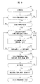
図7は本実施例1の空気調和機の制御を説明するフロー図であり、以下この図7を用いて本実施例1の制御フローを説明する。
図7において、ステップA1で空気調和機(室内機1)の冷房運転が開始され、更にステップA2で冷え過ぎ軽減制御が有効(ON)にされると、ステップA3で人の活動量が検知される。即ち、図1に示す人感センサ(人検知装置)19によりその検知エリア内の人の存在有無や検知エリア内の人の活動量が検知され出力される。また、前記ステップA3では、図1に示す輻射温度センサ(輻射温度検知装置)18を用いて床面の輻射温度も検知される。
なお、前記人感センサ19は人の存在有無だけでなく、人の活動量も検出できるように構成されており、本実施例1では検出された人の活動量も用いて制御する。
図7において、ステップA1で空気調和機(室内機1)の冷房運転が開始され、更にステップA2で冷え過ぎ軽減制御が有効(ON)にされると、ステップA3で人の活動量が検知される。即ち、図1に示す人感センサ(人検知装置)19によりその検知エリア内の人の存在有無や検知エリア内の人の活動量が検知され出力される。また、前記ステップA3では、図1に示す輻射温度センサ(輻射温度検知装置)18を用いて床面の輻射温度も検知される。
なお、前記人感センサ19は人の存在有無だけでなく、人の活動量も検出できるように構成されており、本実施例1では検出された人の活動量も用いて制御する。
前記ステップA3で、検知エリアにおける人の存在を検知しないとき、或いは人の活動量が0(または微少)のときには、輻射温度センサ18で検知された輻射温度に対する補正値αは0(α=0)としてステップA5に出力する。また、前記ステップA3で、検知エリアにおける人の存在を検知したとき、或いは人の活動量が一定値以上の場合、ステップA4に移行し、検知された人の活動量に応じて、前記輻射温度センサ18で検知された輻射温度に対する補正値α(α>0)を出力し、ステップA5に移行する。この補正値αの値は、前記人感センサ19で検知された人の活動量に応じてその大きさが予め決められている。
ステップA5では、前記輻射温度センサ18で検知された輻射温度Aに対して前記補正値αを減算した値を、空気調和機(室内機1)の設定温度と比較し、この設定温度よりも「A-α」の値が大きい場合(Noの場合)、冷え過ぎ状態とはなっていないと判断し、冷え過ぎ軽減制御を開始せずに前記ステップA3に戻り、同様の動作を繰り返す。
ステップA5での比較結果、前記設定温度よりも「A-α」の値の方が小さい場合(Yesの場合)、冷え過ぎの状態であると判断し、ステップA6に移行して、冷え過ぎ軽減制御を開始する。この冷え過ぎ軽減制御では、空気調和機の前記設定温度をより高い温度に設定したり、前記ルーバ7の風向を水平方向に変更して、人に吹出し風が当たらない風よけ設定にする。また、前記吹出口5から吹出される吹出し空気の吹出し風量を減少させるように制御する。
前記設定温度をより高い温度に変更する場合、その変更量は、前記設定温度と、測定された前記輻射温度Aまたは輻射温度の測定値を補正した値(A-α)との差に応じて予め定めた補正量に基づいて決めるようにすると良い。また、前記吹出し風量を減少させる制御は、現在の風量に対して例えば1タップ分減少させる。即ち、現在の設定が、H急風設定(急風設定における風量よりも更に大風量)の状態であれば通常の急風設定とするように変更すると良い。
なお、前記冷え過ぎ軽減制御では、前記設定温度、前記ルーバ7の風向、及び前記吹出し風量の少なくとも何れか一つまたは2つを変更するように制御しても、或いは全てを変更するように制御しても良い。
次に、ステップA7に移行し、冷え過ぎ軽減制御の終了条件、例えば、前記「A-α」の値が前記設定温度よりも大きくなったか否かを判定し、大きくなっていなければ(Noの場合)ステップA6の冷え過ぎ軽減制御を継続し、前記判定の結果、前記「A-α」の値が前記設定温度よりも大きくなっていれば(Yesの場合)ステップA8に移り、冷え過ぎ軽減制御を終了するため、変更した前記設定温度、風向、風量をクリアして元に戻し、冷え過ぎ軽減制御を終了する(ステップA9)。なお、その後も、図7に示すA3~A9の制御フローを繰り返し実施する構成にすると良い。
このように、本実施例1では、人の活動量に応じて前記補正値αを出力するようにしているので、輻射温度センサ18で検知された輻射温度Aに前記補正値αを減算することで、冷え過ぎ状態にあるか否かを正確に判断できる。この結果、室内に居る人の影響をなくす或いは軽減することができるので、冷え過ぎ軽減制御を時間遅れなく、適切なタイミングで開始することができる。
図8は、本実施例2の空気調和機の制御を説明するフロー図であり、以下本実施例2の空気調和機の制御フローをこの図8を用いて説明する。なお、本実施例2の説明においては、上述した実施例1と同様の部分については説明を省略し、異なる部分を中心に説明する。図1~図3に示す空気調和機の構成は実施例1で説明したものと同様であり、図8に示す制御フローだけが異なる。また、図4及び図5に示す説明図も同様であるので、以下の説明では必要に応じ図1~図5も引用しながら説明する。
本実施例2は、前記輻射温度センサ18が、前記吹出口5から吹き出される吹出し風の影響を受ける位置に設けられている場合、冷房運転時には、前記輻射温度センサ18で測定された輻射温度が吹出し風の影響を受けて、実際の床面温度Bよりも低めの値が出力されてしまう。
そこで、本実施例2では、冷房運転時には、前記輻射温度センサ18により測定された輻射温度に対し、吹出し風の影響に基づいて予め定めた補正値βを加えて出力し、この補正値を加えた値を前記設定温度と比較するようにしたものである。このように、輻射温度センサ18で検知された輻射温度に対してその値がより高くなるように補正することで、吹出し空気の影響を無くするようにしたものである。
以下、図8に基づいて説明するが、図7の制御フローと異なる部分を中心に説明する。
冷房運転が開始されると(ステップA1)、次のステップB1では、輻射温度センサ18に吹出し風が当たるか否かを判定し、輻射温度センサ18に吹出し風が当たらない場合(Noの場合)には、補正値βが0(β=0)を出力して、ステップA2に移行し、以下図7に示す実施例1と同様に、ステップA2~A9を実行する。なお、この場合ステップA5でのβは0であるので、図7の場合と同様になる。
冷房運転が開始されると(ステップA1)、次のステップB1では、輻射温度センサ18に吹出し風が当たるか否かを判定し、輻射温度センサ18に吹出し風が当たらない場合(Noの場合)には、補正値βが0(β=0)を出力して、ステップA2に移行し、以下図7に示す実施例1と同様に、ステップA2~A9を実行する。なお、この場合ステップA5でのβは0であるので、図7の場合と同様になる。
輻射温度センサ18に吹出し風が当たる場合(Yesの場合)には、ステップB2に移行し、輻射温度センサ18で検出された輻射温度Aに対して補正値β(β>0)を加えて出力し、ステップA2に移行する。以下のフローは、図7に示す実施例1と同様に、ステップA2~A9を実行する。なお、この場合ステップA5でのβは0より大であり、「輻射温度A+β-α」の値と、空気調和機の設定温度を比較する。その結果、「A+β-α」の値が設定温度以上の場合(Noの場合)には、ステップA3に戻って同様の動作を繰り返し、「A+β-α」の値が設定温度よりも小さくなれば(Yesの場合)、ステップA6に移行して冷え過ぎ軽減制御を実施する。以下のフローは図7の場合と同様である。
このように、本実施例2によれば、輻射温度センサ18に吹出空気が当たる場合、前記輻射温度センサ18で検出される輻射温度Aに対し補正値βを加えることにより、輻射温度センサ18に吹出し空気があたることによる影響を無くすように補正することができる。従って、床面温度Bをより正確に測定することができ、冷え過ぎ軽減制御を適切に実行することができる。
図9は、本実施例3の空気調和機の制御を説明するフロー図であり、以下本実施例3の空気調和機の制御フローをこの図9を用いて説明する。なお、本実施例3の説明においても、上述した実施例1と同様の部分については説明を省略し、異なる部分を中心に説明する。図1~図3に示す空気調和機の構成は実施例1と同様であり、図9に示す制御フローだけが異なる。また、図4及び図5に示す説明図も同様であるので、以下の説明では必要に応じ図1~図5も引用しながら説明する。
本実施例3は、空気調和機が冷房運転を開始して所定時間経過した後、冷え過ぎ軽減制御を開始するように構成したものである。即ち、ステップA1で空気調和機(室内機1)の冷房運転が開始され、更にステップA2で冷え過ぎ軽減制御が有効(ON)にされている場合、運転開始後の運転時間が計測され、ステップC1において、予め定めた所定時間を経過したか否かを判定する。前記所定時間を経過していなければ(Noの場合)、ステップA2に戻り、所定時間経過していれば(Yesの場合)、冷房運転が安定した状態になっていると判定してステップA3に移行するようにしたものである。
以下の制御フローは図7に示すステップA3~A9と同様であるので、それらのステップの説明は省略する。
本実施例3によれば、冷房運転開始後、所定時間経過した後に冷え過ぎ軽減制御の制御フロー(ステップA3~A9)を実施するようにしたので、空調される部屋(室内)の温度が安定した後に、冷え過ぎ軽減制御を開始することができる。従って、安定した冷え過ぎ軽減制御が可能になる効果が得られる。
本実施例3によれば、冷房運転開始後、所定時間経過した後に冷え過ぎ軽減制御の制御フロー(ステップA3~A9)を実施するようにしたので、空調される部屋(室内)の温度が安定した後に、冷え過ぎ軽減制御を開始することができる。従って、安定した冷え過ぎ軽減制御が可能になる効果が得られる。
図10は本実施例4の空気調和機の制御を説明するフロー図であり、以下本実施例4の空気調和機の制御フローをこの図10を用いて説明する。なお、本実施例4の説明において、上述した実施例1~3と同様の部分については説明を省略し、異なる部分を中心に説明する。また、図1~図3に示す空気調和機の構成は実施例1で説明したものと同様であり、上記実施例1~3とは図10に示す制御フローだけが異なっている。また、図4及び図5に示す説明図も同様であるので、以下の説明では必要に応じ図1~図5も引用しながら説明する。
本実施例4は、図7に示す実施例1のフローに、図8に示す実施例2のステップB1,B2を追加し、更に、図9に示す実施例3のステップC1の制御も加えたものである。
即ち、冷房運転が開始されると(ステップA1)、次のステップB1では、輻射温度センサ18に吹出し風が当たるか否かを判定し、輻射温度センサ18に吹出し風が当たらない場合(Noの場合)には、補正値βが0(β=0)を出力し、ステップA2に移行する。輻射温度センサ18に吹出し風が当たる場合(Yesの場合)には、ステップB2に移行し、輻射温度センサ18で検出された輻射温度Aに対する補正値β(β>0)を出力し、ステップA2に移行する。
また、本実施例4では、冷房運転が開始されると(ステップA1)、開始後の運転時間を計測し、前記ステップA2で、冷え過ぎ軽減制御が有効(ON)の状態であれば、ステップC1に移行して、予め定めた所定時間を経過したか否かを判定する。前記所定時間が経過していなければ(Noの場合)、ステップA2に戻り、前記所定時間が経過していれば(Yesの場合)、冷房運転が安定した状態になっていると判定してステップA3に移行するようにしたものである。
以下の制御フローは図8に示すステップA3~A9と同様であるので、それらのステップの説明については省略する。
以下の制御フローは図8に示すステップA3~A9と同様であるので、それらのステップの説明については省略する。
本実施例4によれば、人の在による影響、及び輻射温度センサ18に吹出空気があたることの影響をなくし、検出される輻射温度Aに対して前述した補正値α,βによる補正を与えて(減算または加算して)、床面温度Bをより正確に推定し、更に空調が安定した室内空間に対して冷え過ぎ軽減制御を開始できるので、冷え過ぎの判定をより正確に行うことが可能となり、より適切なタイミングで冷え過ぎ軽減制御を開始できる効果が得られる。
以上説明したように、本発明の空気調和機の各実施例のものは、複数の吹出口と、前記各吹出口に設けられ吹出し方向を調節可能に構成されている複数のルーバと、予め定めた所定の条件になると冷え過ぎ軽減制御を実行する制御装置と、室内の人を検知する人感センサ(人検知装置)を備えている。また、前記制御装置は、前記人感センサが人を検知すると、前記冷え過ぎ軽減制御の前記所定の開始条件を、冷え過ぎ軽減制御を開始し易くなるように補正する。即ち、室内に人が存在する場合にはそれによる温度上昇を加味して、冷え過ぎ軽減制御を開始し易くなるように、測定された輻射温度Aに対し補正値αを減算する補正をする。
従って、本発明の各実施例によれば、床面温度が低くなった場合、輻射温度センサの検知エリア内に人がたくさん存在する場合であっても、適切なタイミングで冷え過ぎ軽減制御を開始できる効果が得られる。
なお、以上説明した各実施例では、冷え過ぎか否かの判定を、測定された輻射温度Aまたはこれに補正値αを減算した値が、室内機の設定温度よりも小さい場合に冷え過ぎと判定する例を説明したが、検出された輻射温度Aまたはこれに補正値αを減算した値と室内機の設定温度とを比較し、その差が予め定めた所定温度以上となった場合に冷え過ぎと判定するようにしても良い。
また、上述した各実施例では、前記人感センサにより人を検知すると、測定された輻射温度Aから補正値αを減算して冷え過ぎ軽減制御を開始し易くなるようにした例を説明したが、これに代えて以下のように構成しても同様の効果が得られる。即ち、前記人感センサにより人を検知すると、室内機の設定温度に補正値(例えば前記補正値αと同じ値)を加算することにより、冷え過ぎ軽減制御を開始し易くなるように構成しても良い。このように、人感センサにより人を検知すると、測定された輻射温度または室内機の設定温度の少なくとも何れかに、冷え過ぎ軽減制御を開始し易くなるように補正値を与える(減算または加算する)ようにすれば良い。
なお、本発明は上述した実施例に限定されるものではなく、様々な変形例が含まれる。また、上記した実施例は本発明を分かりやすく説明するために詳細に説明したものであり、必ずしも説明した全ての構成を備えるものに限定されるものではない。
1:空気調和機(室内機)、2:筐体、3:化粧パネル、3a:断熱材、4:吸込口、5:吹出口、6:吸込グリル、7:ルーバ、7a:最小角度(第1角度)の位置、7b:最大角度(第2角度)の位置、8:モータ、9:遠心ファン、10:熱交換器、11:ドレンパン、12:吸込部、13:吐出部、14:風路、15:ベルマウス、16:電気品箱、17:吸込フィルタ、18:輻射温度センサ(輻射温度検知装置)、19:人感センサ(人検知装置)、20:天井、21:中心軸、22:取付部材、A:輻射温度センサが検知する輻射温度、B:床面温度、C:天井付近の空気温度、D:吹出し空気温度、α,β:補正値。
Claims (11)
- 複数の吹出口と、前記各吹出口に設けられ吹出し方向を調節可能に構成されている複数のルーバを備える空気調和機において、
予め定めた所定の条件になると冷え過ぎ軽減制御を実行する制御装置と、
室内の人を検知する人検知装置と、を備え、
前記制御装置は、前記人検知装置が人を検知すると、前記冷え過ぎ軽減制御の前記所定の開始条件を、冷え過ぎ軽減制御を開始し易くなるように補正する
ことを特徴とする空気調和機。 - 請求項1に記載の空気調和機において、
床面からの輻射温度を検知して床面温度を測定する輻射温度検知装置を備え、
前記制御装置は、空気調和機の設定温度と、前記輻射温度検知装置で測定された輻射温度を比較し、前記設定温度よりも前記輻射温度が低くなると前記冷え過ぎ軽減制御を開始するように構成し、
前記人検知装置により人を検知すると、前記輻射温度または前記設定温度の少なくとも何れかに冷え過ぎ軽減制御を開始し易くなるように補正値を与える
ことを特徴とする空気調和機。 - 請求項2に記載の空気調和機において、
前記人検知装置により人を検知すると、前記輻射温度検知装置で測定された前記輻射温度から予め定めた補正値を減算して、前記設定温度と比較することにより、冷え過ぎ軽減制御を開始し易くすることを特徴とする空気調和機。 - 請求項2に記載の空気調和機において、
前記人検知装置は人検知エリアに存在する人の活動量を出力するものであり、前記補正値は前記活動量に応じて予め決められていることを特徴とする空気調和機。 - 請求項4に記載の空気調和機において、
前記人検知装置から出力された人の活動量に応じて決められた前記補正値を、前記輻射温度検知装置で測定された前記輻射温度から減算して前記設定温度と比較することを特徴とする空気調和機。 - 請求項2に記載の空気調和機において、
前記輻射温度検知装置が前記吹出口から吹き出される吹出し風の影響を受ける位置に設けられている場合、冷房運転時には、前記輻射温度検知装置により測定された輻射温度に対し吹出し風の影響に基づいて予め定めた補正値を加算して、前記設定温度と比較することを特徴とする空気調和機。 - 請求項5に記載の空気調和機において、
空気調和機の運転開始して所定時間経過した後、人の活動量に応じて決められた前記補正値を、前記輻射温度検知装置で測定された前記輻射温度から減算して前記設定温度と比較することを特徴とする空気調和機。 - 請求項7に記載の空気調和機において、
前記輻射温度検知装置が前記吹出口から吹き出される吹出し風の影響を受ける位置に設けられている場合、冷房運転時には、前記輻射温度検知装置により測定された輻射温度に対し吹出し風の影響に基づいて予め定めた補正値を加算して、前記設定温度と比較することを特徴とする空気調和機。 - 請求項2に記載の空気調和機において、
前記冷え過ぎ軽減制御が開始されると、空気調和機の前記設定温度、前記ルーバによる風向、吹出し風量の少なくとも何れかを変更して冷え過ぎ軽減制御を行うことを特徴とする空気調和機。 - 請求項9に記載の空気調和機において、
前記冷え過ぎ軽減制御が開始されると、少なくとも前記設定温度が変更されるものであり、且つ前記設定温度の変更量は、前記設定温度と、測定された前記輻射温度または輻射温度の測定値を補正した値との差に応じて予め定めた補正量に基づいて決められることを特徴とする空気調和機。 - 請求項10に記載の空気調和機において、
前記冷え過ぎ軽減制御が開始されると、前記設定温度が変更されると共に、前記ルーバの風向を水平方向とし、且つ、前記吹出し風量を減少させることを特徴とする空気調和機。
Priority Applications (1)
| Application Number | Priority Date | Filing Date | Title |
|---|---|---|---|
| PCT/JP2018/005186 WO2019159271A1 (ja) | 2018-02-15 | 2018-02-15 | 空気調和機 |
Applications Claiming Priority (1)
| Application Number | Priority Date | Filing Date | Title |
|---|---|---|---|
| PCT/JP2018/005186 WO2019159271A1 (ja) | 2018-02-15 | 2018-02-15 | 空気調和機 |
Publications (1)
| Publication Number | Publication Date |
|---|---|
| WO2019159271A1 true WO2019159271A1 (ja) | 2019-08-22 |
Family
ID=67619207
Family Applications (1)
| Application Number | Title | Priority Date | Filing Date |
|---|---|---|---|
| PCT/JP2018/005186 Ceased WO2019159271A1 (ja) | 2018-02-15 | 2018-02-15 | 空気調和機 |
Country Status (1)
| Country | Link |
|---|---|
| WO (1) | WO2019159271A1 (ja) |
Cited By (3)
| Publication number | Priority date | Publication date | Assignee | Title |
|---|---|---|---|---|
| CN111780321A (zh) * | 2020-06-11 | 2020-10-16 | 宁波奥克斯电气股份有限公司 | 空调器的控制方法、控制装置及空调器 |
| CN113124495A (zh) * | 2021-05-14 | 2021-07-16 | 宁波奥克斯电气股份有限公司 | 一种空调器、风量控制方法及装置 |
| CN114992792A (zh) * | 2022-06-29 | 2022-09-02 | 珠海格力电器股份有限公司 | 一种空调器的控制方法、装置、存储介质及空调器 |
Citations (4)
| Publication number | Priority date | Publication date | Assignee | Title |
|---|---|---|---|---|
| JPH0666442A (ja) * | 1992-08-18 | 1994-03-08 | Toshiba Corp | 空調制御装置 |
| JP2002310492A (ja) * | 2000-10-04 | 2002-10-23 | Sharp Corp | 空気調和機 |
| JP2011185591A (ja) * | 2010-02-15 | 2011-09-22 | Daikin Industries Ltd | 空気調和装置の室内ユニット |
| JP2012057814A (ja) * | 2010-09-06 | 2012-03-22 | Hitachi Appliances Inc | 空気調和機 |
-
2018
- 2018-02-15 WO PCT/JP2018/005186 patent/WO2019159271A1/ja not_active Ceased
Patent Citations (4)
| Publication number | Priority date | Publication date | Assignee | Title |
|---|---|---|---|---|
| JPH0666442A (ja) * | 1992-08-18 | 1994-03-08 | Toshiba Corp | 空調制御装置 |
| JP2002310492A (ja) * | 2000-10-04 | 2002-10-23 | Sharp Corp | 空気調和機 |
| JP2011185591A (ja) * | 2010-02-15 | 2011-09-22 | Daikin Industries Ltd | 空気調和装置の室内ユニット |
| JP2012057814A (ja) * | 2010-09-06 | 2012-03-22 | Hitachi Appliances Inc | 空気調和機 |
Cited By (3)
| Publication number | Priority date | Publication date | Assignee | Title |
|---|---|---|---|---|
| CN111780321A (zh) * | 2020-06-11 | 2020-10-16 | 宁波奥克斯电气股份有限公司 | 空调器的控制方法、控制装置及空调器 |
| CN113124495A (zh) * | 2021-05-14 | 2021-07-16 | 宁波奥克斯电气股份有限公司 | 一种空调器、风量控制方法及装置 |
| CN114992792A (zh) * | 2022-06-29 | 2022-09-02 | 珠海格力电器股份有限公司 | 一种空调器的控制方法、装置、存储介质及空调器 |
Similar Documents
| Publication | Publication Date | Title |
|---|---|---|
| KR102168705B1 (ko) | 천장형 공기조화기의 제어방법 | |
| JP5063509B2 (ja) | 空気調和機 | |
| JP6222211B2 (ja) | 空気調和装置 | |
| US20210102725A1 (en) | Indoor unit of air conditioner | |
| WO2019024826A1 (zh) | 壁挂式空调室内机及其控制方法 | |
| CN105180268B (zh) | 空调室内机及空调室内出风控制方法 | |
| JP6808999B2 (ja) | 空気調和機 | |
| JP6498598B2 (ja) | 制御装置、及びそれを備えた空気調和システム、並びに制御方法 | |
| JP2016217618A (ja) | 室内空調システム | |
| JP6135734B2 (ja) | 空気調和装置の室内ユニット | |
| CN106196409A (zh) | 室内风机的控制方法、控制装置和壁挂式空调 | |
| JP6625210B2 (ja) | 天井埋込形空気調和装置 | |
| JPWO2018150535A1 (ja) | 室内機および空気調和装置 | |
| JP4478082B2 (ja) | 空気調和機の制御方法 | |
| KR20100048545A (ko) | 공기조화기 및 그 제어방법 | |
| JP2020024071A (ja) | 環境制御システムおよび空気調和装置 | |
| WO2019111308A1 (ja) | 空気調和機の室内機 | |
| JP6418147B2 (ja) | 空調機 | |
| JP6540336B2 (ja) | 空気調和機 | |
| JP6237755B2 (ja) | 室内機 | |
| JP4169861B2 (ja) | 天井カセット形空気調和装置の運転制御装置 | |
| JP4610601B2 (ja) | 天吊形空気調和機 | |
| CN105180271B (zh) | 空调室内机及空调室内出风控制方法 | |
| JP6609722B1 (ja) | 空気調和機の室内機 | |
| JP5381066B2 (ja) | 空気調和装置の室内機およびこれを備えた空気調和装置 |
Legal Events
| Date | Code | Title | Description |
|---|---|---|---|
| 121 | Ep: the epo has been informed by wipo that ep was designated in this application |
Ref document number: 18906575 Country of ref document: EP Kind code of ref document: A1 |
|
| NENP | Non-entry into the national phase |
Ref country code: DE |
|
| 122 | Ep: pct application non-entry in european phase |
Ref document number: 18906575 Country of ref document: EP Kind code of ref document: A1 |
|
| NENP | Non-entry into the national phase |
Ref country code: JP |