WO2019150753A1 - 内視鏡 - Google Patents
内視鏡 Download PDFInfo
- Publication number
- WO2019150753A1 WO2019150753A1 PCT/JP2018/044576 JP2018044576W WO2019150753A1 WO 2019150753 A1 WO2019150753 A1 WO 2019150753A1 JP 2018044576 W JP2018044576 W JP 2018044576W WO 2019150753 A1 WO2019150753 A1 WO 2019150753A1
- Authority
- WO
- WIPO (PCT)
- Prior art keywords
- rotating shaft
- shaft
- hole
- endoscope
- housing
- Prior art date
- Legal status (The legal status is an assumption and is not a legal conclusion. Google has not performed a legal analysis and makes no representation as to the accuracy of the status listed.)
- Ceased
Links
Images






Classifications
-
- A—HUMAN NECESSITIES
- A61—MEDICAL OR VETERINARY SCIENCE; HYGIENE
- A61B—DIAGNOSIS; SURGERY; IDENTIFICATION
- A61B1/00—Instruments for performing medical examinations of the interior of cavities or tubes of the body by visual or photographical inspection, e.g. endoscopes; Illuminating arrangements therefor
- A61B1/00064—Constructional details of the endoscope body
- A61B1/00071—Insertion part of the endoscope body
- A61B1/0008—Insertion part of the endoscope body characterised by distal tip features
- A61B1/00098—Deflecting means for inserted tools
-
- A—HUMAN NECESSITIES
- A61—MEDICAL OR VETERINARY SCIENCE; HYGIENE
- A61B—DIAGNOSIS; SURGERY; IDENTIFICATION
- A61B1/00—Instruments for performing medical examinations of the interior of cavities or tubes of the body by visual or photographical inspection, e.g. endoscopes; Illuminating arrangements therefor
- A61B1/00002—Operational features of endoscopes
- A61B1/00004—Operational features of endoscopes characterised by electronic signal processing
- A61B1/00006—Operational features of endoscopes characterised by electronic signal processing of control signals
-
- A—HUMAN NECESSITIES
- A61—MEDICAL OR VETERINARY SCIENCE; HYGIENE
- A61B—DIAGNOSIS; SURGERY; IDENTIFICATION
- A61B1/00—Instruments for performing medical examinations of the interior of cavities or tubes of the body by visual or photographical inspection, e.g. endoscopes; Illuminating arrangements therefor
- A61B1/00064—Constructional details of the endoscope body
- A61B1/00071—Insertion part of the endoscope body
- A61B1/0008—Insertion part of the endoscope body characterised by distal tip features
- A61B1/00087—Tools
-
- A—HUMAN NECESSITIES
- A61—MEDICAL OR VETERINARY SCIENCE; HYGIENE
- A61B—DIAGNOSIS; SURGERY; IDENTIFICATION
- A61B1/00—Instruments for performing medical examinations of the interior of cavities or tubes of the body by visual or photographical inspection, e.g. endoscopes; Illuminating arrangements therefor
- A61B1/00064—Constructional details of the endoscope body
- A61B1/00071—Insertion part of the endoscope body
- A61B1/0008—Insertion part of the endoscope body characterised by distal tip features
- A61B1/00101—Insertion part of the endoscope body characterised by distal tip features the distal tip features being detachable
-
- A—HUMAN NECESSITIES
- A61—MEDICAL OR VETERINARY SCIENCE; HYGIENE
- A61B—DIAGNOSIS; SURGERY; IDENTIFICATION
- A61B1/00—Instruments for performing medical examinations of the interior of cavities or tubes of the body by visual or photographical inspection, e.g. endoscopes; Illuminating arrangements therefor
- A61B1/00064—Constructional details of the endoscope body
- A61B1/0011—Manufacturing of endoscope parts
-
- A—HUMAN NECESSITIES
- A61—MEDICAL OR VETERINARY SCIENCE; HYGIENE
- A61B—DIAGNOSIS; SURGERY; IDENTIFICATION
- A61B1/00—Instruments for performing medical examinations of the interior of cavities or tubes of the body by visual or photographical inspection, e.g. endoscopes; Illuminating arrangements therefor
- A61B1/00131—Accessories for endoscopes
- A61B1/00137—End pieces at either end of the endoscope, e.g. caps, seals or forceps plugs
-
- A—HUMAN NECESSITIES
- A61—MEDICAL OR VETERINARY SCIENCE; HYGIENE
- A61B—DIAGNOSIS; SURGERY; IDENTIFICATION
- A61B1/00—Instruments for performing medical examinations of the interior of cavities or tubes of the body by visual or photographical inspection, e.g. endoscopes; Illuminating arrangements therefor
- A61B1/012—Instruments for performing medical examinations of the interior of cavities or tubes of the body by visual or photographical inspection, e.g. endoscopes; Illuminating arrangements therefor characterised by internal passages or accessories therefor
- A61B1/018—Instruments for performing medical examinations of the interior of cavities or tubes of the body by visual or photographical inspection, e.g. endoscopes; Illuminating arrangements therefor characterised by internal passages or accessories therefor for receiving instruments
-
- A—HUMAN NECESSITIES
- A61—MEDICAL OR VETERINARY SCIENCE; HYGIENE
- A61B—DIAGNOSIS; SURGERY; IDENTIFICATION
- A61B8/00—Diagnosis using ultrasonic, sonic or infrasonic waves
- A61B8/12—Diagnosis using ultrasonic, sonic or infrasonic waves in body cavities or body tracts, e.g. by using catheters
-
- G—PHYSICS
- G02—OPTICS
- G02B—OPTICAL ELEMENTS, SYSTEMS OR APPARATUS
- G02B23/00—Telescopes, e.g. binoculars; Periscopes; Instruments for viewing the inside of hollow bodies; Viewfinders; Optical aiming or sighting devices
- G02B23/24—Instruments or systems for viewing the inside of hollow bodies, e.g. fibrescopes
-
- A—HUMAN NECESSITIES
- A61—MEDICAL OR VETERINARY SCIENCE; HYGIENE
- A61B—DIAGNOSIS; SURGERY; IDENTIFICATION
- A61B1/00—Instruments for performing medical examinations of the interior of cavities or tubes of the body by visual or photographical inspection, e.g. endoscopes; Illuminating arrangements therefor
- A61B1/005—Flexible endoscopes
- A61B1/0051—Flexible endoscopes with controlled bending of insertion part
-
- A—HUMAN NECESSITIES
- A61—MEDICAL OR VETERINARY SCIENCE; HYGIENE
- A61B—DIAGNOSIS; SURGERY; IDENTIFICATION
- A61B1/00—Instruments for performing medical examinations of the interior of cavities or tubes of the body by visual or photographical inspection, e.g. endoscopes; Illuminating arrangements therefor
- A61B1/06—Instruments for performing medical examinations of the interior of cavities or tubes of the body by visual or photographical inspection, e.g. endoscopes; Illuminating arrangements therefor with illuminating arrangements
- A61B1/0661—Endoscope light sources
Definitions
- the present invention relates to an endoscope.
- an endoscope in which a treatment tool such as a forceps can protrude from the distal end of an insertion portion to be inserted into a subject (for example, see Patent Document 1).
- the operation wire provided in the insertion portion moves by operating the operation portion provided on the proximal end side of the insertion portion, and the rotating shaft rotates to raise the raising base.
- the rotating shaft is supported by the shaft hole of the housing located between the position where the wire is connected and the raising base.
- the rotation axis may tilt. If the rotation shaft is tilted, watertightness may not be ensured or rotation failure may occur. For this reason, the technique which prevents that a rotating shaft inclines was calculated
- the present invention has been made in view of the above, and an object of the present invention is to provide an endoscope that prevents the rotation shaft for raising the elevator from being tilted.
- an endoscope is an endoscope that is capable of inserting a treatment tool and is disposed at a distal end of the endoscope, and the treatment A distal end rigid portion in which an opening from which the instrument protrudes is formed; a treatment instrument raising base that is located in the opening and changes a direction in which the treatment instrument protrudes by contacting the treatment instrument; and one end of the treatment instrument A rotation shaft fixed to the device raising base and rotatable integrally with the treatment device raising base; an arm portion fixed to the rotation shaft and rotating the rotation shaft in response to an operation on the operation portion; A first bearing portion that is positioned closer to the treatment instrument elevator base than the arm portion in the axial direction of the rotation shaft, and has a first shaft hole that rotatably supports the rotation shaft; and the shaft In the direction, the first bearing portion with respect to the arm portion A housing having a second bearing portion that is located on the opposite side and that is formed with a second shaft hole that
- the endoscope according to one aspect of the present invention is characterized in that the rotating shaft is fixed to the arm portion by a spring pin or a pin screw.
- the arm portion is formed with a through hole having a flat portion extending in a direction perpendicular to the axial direction, and the outer periphery of the rotating shaft is formed on the outer periphery of the rotating shaft.
- a planar portion extending in a direction orthogonal to the axial direction is formed, and the through-hole and the rotating shaft are in a state where the planar portion of the through-hole and the planar portion of the rotating shaft are opposed to each other. Are fitted.
- a housing seal that keeps the distal end hard portion and the housing watertight is located between the distal end hard portion and the first bearing portion. It is characterized by.
- the endoscope according to one aspect of the present invention is characterized in that a fitting groove into which the seal member is fitted is formed on the outer periphery of the rotating shaft.
- the rotation axis of the treatment instrument raising base, the rotation axis of the arm unit, and the axes of the first shaft hole and the second shaft hole are provided. It is characterized by being on the same straight line.
- the endoscope according to one aspect of the present invention is characterized in that the housing is detachably fixed to the hard tip portion.
- the endoscope includes an ultrasonic transducer.
- FIG. 1 is a schematic diagram showing a configuration of an endoscope according to an embodiment of the present invention.
- FIG. 2 is a schematic partial cross-sectional view of the distal end portion of the endoscope shown in FIG.
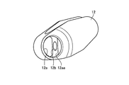
- FIG. 3 is a side view of the forceps raising base shown in FIG.
- FIG. 4 is a perspective view of the rotating shaft shown in FIG.
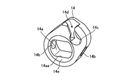
- FIG. 5 is a perspective view of the arm portion shown in FIG.
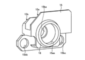
- FIG. 6 is a perspective view of the housing shown in FIG.
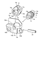
- FIG. 7 is a diagram for explaining an endoscope assembling method.
- FIG. 8 is a diagram for explaining an endoscope assembling method.
- FIG. 9 is a diagram for explaining an endoscope assembling method.
- FIG. 10 is a diagram for explaining an endoscope assembling method.
- FIG. 10 is a diagram for explaining an endoscope assembling method.
- FIG. 11 is a diagram for explaining an endoscope assembling method.
- FIG. 12 is a diagram for explaining an endoscope assembling method.
- FIG. 13 is a diagram for explaining an endoscope assembling method.
- FIG. 14 is a diagram illustrating a partial configuration of the distal end portion of the endoscope according to the first modification of the embodiment.
- FIG. 15 is a diagram illustrating a partial configuration of the distal end portion of the endoscope according to the second modification of the embodiment.
- Embodiments of an endoscope according to the present invention will be described below with reference to the drawings. Note that the present invention is not limited to these embodiments.
- the present invention can be generally applied to an endoscope including a treatment instrument raising base.
- FIG. 1 is a schematic diagram showing a configuration of an endoscope according to an embodiment of the present invention.
- the endoscope 1 is provided with an imaging unit at a distal end, an insertion unit 2 inserted into a subject, an operation unit 3 connected to a proximal end side of the insertion unit 2, and an operation unit 3.
- a universal cord 4 extending from the side, a connector portion connected to the universal cord 4 and connected to an observation device for controlling the endoscope 1 and a light source device for supplying illumination light to the endoscope 1 5 is provided.
- FIG. 1 is a schematic diagram showing a configuration of an endoscope according to an embodiment of the present invention.
- the endoscope 1 is provided with an imaging unit at a distal end, an insertion unit 2 inserted into a subject, an operation unit 3 connected to a proximal end side of the insertion unit 2, and an operation unit 3.
- a universal cord 4 extending from the side, a connector portion connected to the universal cord 4 and connected to an observation device for controlling
- insertion direction the direction in which the insertion portion 2 is inserted in the longitudinal direction of the endoscope 1
- distal end side in the insertion direction
- base end side The “front end side” and the base end side (downward in FIG. 1) are defined as “base end side”.
- the insertion portion 2 includes, in order from the distal end side, a distal end portion 2a, a bending portion 2b configured to be bendable according to an operation of the operation portion 3, and a flexible tube portion 2c having flexibility.
- the proximal end of the flexible tube portion 2 c is connected to the distal end side of the operation portion 3.
- An ultrasonic transducer 2aa is disposed at the tip of the tip 2a.
- the endoscope 1 may be an endoscope that does not have an ultrasonic transducer.
- the operation unit 3 is provided with a forceps insertion port 3a for inserting a forceps needle or the like as a treatment tool into the subject.
- a forceps insertion passage is provided in the insertion portion 2, and the forceps insertion port 3a is an insertion port for the forceps insertion passage. That is, the endoscope 1 is an endoscope through which a treatment tool can be inserted.
- the operation unit 3 receives an operation for rotating a rotation shaft described later.
- FIG. 2 is a schematic partial cross-sectional view of the distal end portion of the endoscope shown in FIG. FIG. 2 shows a cross section orthogonal to the insertion direction.
- the distal end portion 2a of the endoscope 1 is disposed at the distal end of the endoscope 1 and is located in the distal end rigid portion 11 in which the opening portion 11a is formed, and the opening portion 11a.
- a forceps raising base 12 treatment tool raising base) for changing the direction in which the forceps protrude by contacting the forceps, and one end are fixed to the forceps raising base 12, and are integrated with the forceps raising base 12 around the axis A.
- the tip hard portion 11 is made of, for example, resin.
- FIG. 3 is a side view of the forceps raising base shown in FIG.
- a shaft hole 12 a that fits the rotating shaft 13 is formed on the side surface of the forceps raising base 12.
- the shaft hole 12 a is formed with a flat surface portion 12 aa extending in a direction orthogonal to the axial direction (axis A) of the rotary shaft 13.
- the forceps raising base 12 is formed with a screw hole 12b communicating with the shaft hole 12a.
- a fitting groove 13 f into which the rotary shaft seal 17 is fitted is formed on the outer periphery of the rotary shaft 13.
- the forceps raising base 12 is made of a hard material such as metal, alloy, or ceramic.
- FIG. 4 is a perspective view of the rotating shaft shown in FIG.
- the rotating shaft 13 is formed with a flat surface portion 13a that extends in a direction orthogonal to the axial direction (axis A) of the rotating shaft 13 and faces the flat surface portion 12aa of the shaft hole 12a.
- the flat portion 13a is formed with a groove 13b where a tip of a screw screwed into the screw hole 12b is located.
- a flat surface portion 13c extending in the direction orthogonal to the axial direction (axis A) is formed on the outer periphery of the rotating shaft 13 on the side opposite to the forceps raising base 12.
- a pin hole 13d into which the spring pin 20 is inserted is formed inside the flat portion 13c.
- a through hole 13 e for confirming water tightness between the forceps raising base 12 and the rotary shaft 13 is formed inside the rotary shaft 13. Specifically, when the gas is introduced from the side opposite to the forceps raising base 12 of the through hole 13e in a state where the portion where the forceps raising base 12 and the forceps base seal 19 are in contact with each other is immersed in the liquid, The watertightness between the forceps raising base 12 and the rotating shaft 13 can be confirmed by whether or not it leaks.
- the rotating shaft 13 is made of, for example, a metal or an alloy.
- the surface of the rotating shaft 13 is preferably coated with good slidability.
- the surface of the rotary shaft 13 is coated with DLC (Diamond-Like Carbon), fluorine, plating, or the like.
- DLC Diamond-Like Carbon
- fluorine fluorine
- plating or the like.
- the rotary shaft 13 slides with respect to the rotary shaft seal 17, but when the housing 15 slides with respect to the rotary shaft seal 17, these are placed on the surface of the housing 15.
- a coating is preferably applied.
- FIG. 5 is a perspective view of the arm portion shown in FIG.
- the arm portion 14 is formed with a through hole 14 a through which the rotation shaft 13 is inserted.
- the through hole 14 a extends in a direction orthogonal to the axial direction (axis A), and has a flat surface portion 14 aa facing the flat surface portion 13 c of the rotating shaft 13.
- the through-hole 14a and the rotating shaft 13 are fitted in the state where the flat surface portion 14aa of the through-hole 14a and the flat surface portion 13c of the rotating shaft 13 face each other.
- the arm portion 14 is formed with a pin hole 14b into which the spring pin 20 is inserted.
- the through-hole 14a and the rotating shaft 13 fit, and the rotating shaft 13 and the arm part 14 can be rotated integrally by inserting the spring pin 20 in the pin hole 13d and the pin hole 14b.
- the arm portion 14 is formed with a wire engaging portion 14 c that engages with a cylindrical wire tip portion formed at the tip of the forceps operation wire 16.
- the arm portion 14 is formed with a slit 14d for inserting the wire tip portion into the wire engaging portion 14c so as to be connected to the wire engaging portion 14c.
- the slit 14d is formed at a position where the distal end of the wire can be inserted from above in FIG.
- a stepped portion 14e is formed on the outer periphery of the through hole 14a on both side surfaces of the arm portion 14 (see FIGS. 2 and 5). The formation of the stepped portion 14e prevents the arm portion 14 from being displaced in the axial direction (axis A) with respect to the housing 15.
- the forceps raising base 12 is prevented from moving in the axial direction (axis A), and the forceps raising base 12 can be accurately raised directly above.
- the clearance between the wall surface of the distal end hard portion 11 and the forceps raising base 12 can be kept constant, thereby ensuring cleaning.
- the stepped portion 14e is formed, the area where the arm portion 14 and the housing 15 are in contact with each other is reduced, and the frictional resistance between the arm portion 14 and the housing 15 can be reduced.
- the arm part 14 consists of a metal or an alloy, for example.
- FIG. 6 is a perspective view of the housing shown in FIG.
- the housing 15 includes, in the axial direction (axis A), the first bearing portion 15 a positioned on the forceps raising base 12 side from the arm portion 14 in the axial direction (axis A) of the rotary shaft 13.
- a second bearing portion 15b located on the opposite side of the arm portion 14 from the first bearing portion 15a.
- the housing 15 is made of, for example, metal or alloy, and the first bearing portion 15a and the second bearing portion 15b are integrally formed.
- a first shaft hole 15aa for rotatably supporting the rotary shaft 13 is formed in the first bearing portion 15a.
- a second shaft hole 15ba that is coaxial with the first shaft hole 15aa that rotatably supports the rotary shaft 13 is formed in the second bearing portion 15b.
- the second bearing portion 15b is formed with a screw hole 15bb and a screw hole 15bc that are used when the housing 15 is fixed to the distal end hard portion 11.
- the forceps operation wire 16 extends to the proximal end side, moves in the insertion direction in accordance with an operation on the operation unit 3, and moves through the arm unit 14 and the rotation shaft 13 to move the forceps raising base 12. Rotate.
- the rotary shaft seal 17 is disposed between the fitting groove 13f located on the outer periphery of the rotary shaft 13 and the inner periphery of the first shaft hole 15aa of the first bearing portion 15a.
- the rotary shaft seal 17 is made of an elastic material such as rubber or silicone.
- the housing seal 18 is disposed between the groove 15ab formed in the first bearing portion 15a and the distal end hard portion 11.
- the housing seal 18 is made of an elastic material such as rubber or silicone.
- the forceps table seal 19 is disposed between the groove 13 g formed on the outer periphery of the rotating shaft 13 and the forceps raising table 12.
- the forceps table seal 19 is made of an elastic material such as rubber or silicone.
- FIG. 7 are views for explaining an endoscope assembling method.
- the arm portion 14 is disposed between the first bearing portion 15 a and the second bearing portion 15 b of the housing 15.
- the rotating shaft 13 is connected to the through hole 14a of the arm portion 14 via the first shaft hole 15aa of the first bearing portion 15a so that the flat portion 14aa of the arm portion 14 and the flat portion 13c of the rotating shaft 13 face each other.
- the spring pin 20 is inserted into the pin hole 14 b of the arm portion 14 and the pin hole 13 d of the rotating shaft 13.
- the treatment instrument raising unit shown in FIG. 8 is assembled.
- the rotating shaft of the forceps raising base 12, the rotating shaft of the rotating shaft 13, and the shaft centers of the first shaft hole 15aa and the second shaft hole 15ba are on the same straight line. There is no.
- the base 21 is inserted into the opening 11 b of the distal end hard portion 11.
- the base 21 is made of metal or alloy, and is a base on which the treatment instrument raising unit shown in FIG. 8 is attached.
- the pin 22 is inserted into the pin hole 21 a of the base 21 through the pin hole 11 c of the distal end hard portion 11. Further, the base 21 is adhered to the distal end hard portion 11 with an adhesive or the like.
- a screw hole 21b and a screw hole 21c are formed in the base 21.
- the treatment instrument raising unit shown in FIG. 8 is inserted into the opening 11 b of the distal end hard portion 11 with the forceps raising base 12 disposed in the opening 11 a of the distal end hard portion 11.
- the outer periphery of the first shaft hole 15aa of the first bearing portion 15a is fitted into the through hole 11d of the hard tip portion 11.
- the rotating shaft 13 is inserted into the shaft hole 12 a of the forceps raising base 12.
- the screw 25 is screwed into the screw hole 21b of the base 21 through the screw hole 15bc of the second bearing portion 15b.
- the wire distal end portion 16a of the forceps operation wire 16 is assembled to the wire engaging portion 14c of the arm portion 14 through the slit 14d.
- FIG. 11 is a cross-sectional view along the axis A which is the rotation axis of the rotation shaft 13.
- the screw 23 is screwed into the screw hole 12 b of the forceps raising base 12 in a state where the rotating shaft 13 is inserted into the through hole 11 d of the distal end hard portion 11.
- the forceps raising base 12 and the rotating shaft 13 are fixed.
- the groove 12c of the forceps raising base 12 is sealed with a screw concealing member 24 coated with an adhesive.
- the cover 26 is adhered with an adhesive or the like so as to cover the step portion 11e of the distal end hard portion 11, and the screw 27 is screwed into the screw hole 21c through the hole 26a and the screw hole 15bb. Match. As a result, the space closer to the cover 26 than the rotary shaft seal 17 is kept watertight. Further, the lid 28 is bonded from above with an adhesive. As a result, the distal end portion of the endoscope 1 shown in FIG. 13 is assembled.
- the rotation shaft 13 that rotates the forceps raising base 12 is rotated. Is prevented from tilting. As a result, even if the operation for raising the forceps raising base 12 is repeatedly performed, the watertight state can be maintained and rotation failure can be prevented.
- the inclination generated by the clearance between the rotary shaft 13 and the housing 15 is opposite to the forceps raising base 12 of the second shaft hole 15ba from the end surface toward the forceps raising base 12 of the first shaft hole 15aa.
- the distance to the end face on the side is small, and the amount by which the rotating shaft 13 tilts is small. As a result, the effect of maintaining the watertight state and preventing the occurrence of rotation failure is high.
- FIG. 14 is a diagram illustrating a partial configuration of the distal end portion of the endoscope according to the first modification of the embodiment.
- a screw hole 13Ad is formed in the rotating shaft 13A, and a screw hole 14Ab is formed in the arm portion 14A.
- the pin screw 20A is screwed into the screw hole 13Ad and the screw hole 14Ab.
- a screw may be used instead of the spring pin.
- the recessed part for confirming the watertightness between forceps raising base and the rotating shaft 13A is formed in the center part of the longitudinal direction of the pin screw 20A.
- FIG. 15 is a diagram illustrating a partial configuration of the distal end portion of the endoscope according to the second modification of the embodiment.
- the rotary shaft 13B is press-fitted into the through hole 14Ba of the arm portion 14B.
- the fixing method of an arm part and a rotating shaft is not specifically limited.
- the method for fixing the rotating shaft and the forceps raising base is not particularly limited.
- the hard tip portion 11 may be made of a metal or an alloy.
- the housing 15 may be directly fixed to the distal end hard portion 11 with screws or the like without providing the base 21.
Landscapes
- Life Sciences & Earth Sciences (AREA)
- Health & Medical Sciences (AREA)
- Surgery (AREA)
- Physics & Mathematics (AREA)
- Engineering & Computer Science (AREA)
- Heart & Thoracic Surgery (AREA)
- Molecular Biology (AREA)
- Nuclear Medicine, Radiotherapy & Molecular Imaging (AREA)
- Pathology (AREA)
- Radiology & Medical Imaging (AREA)
- Optics & Photonics (AREA)
- Biomedical Technology (AREA)
- Veterinary Medicine (AREA)
- Medical Informatics (AREA)
- Biophysics (AREA)
- Public Health (AREA)
- Animal Behavior & Ethology (AREA)
- General Health & Medical Sciences (AREA)
- Signal Processing (AREA)
- Astronomy & Astrophysics (AREA)
- General Physics & Mathematics (AREA)
- Manufacturing & Machinery (AREA)
- Endoscopes (AREA)
- Ultra Sonic Daignosis Equipment (AREA)
- Instruments For Viewing The Inside Of Hollow Bodies (AREA)
Abstract
処置具を挿通可能な内視鏡において、先端に配設され、処置具が突出する開口部が形成されている先端硬質部と、開口部内に位置し、処置具が突出する方向を変化させる処置具起上台と、一端が処置具起上台に固定されており、処置具起上台と一体的に回転可能な回転軸と、回転軸に固定されており、操作部に対する操作に応じて回転軸を回転させるアーム部と、回転軸の軸方向において、アーム部より処置具起上台側に位置し、回転軸を回転可能に支持する第1の軸穴が形成されている第1軸受け部、及び軸方向において、アーム部に対して第1軸受け部と反対側に位置し、回転軸を回転可能に支持する第1の軸穴と同軸な第2の軸穴が形成されている第2軸受け部を有するハウジングと、回転軸の外周と第1の軸穴の内周との間に位置するシール部材と、を備える。これにより、起上台を起上させる回転軸が傾くことを防止した内視鏡を提供する。
Description
本発明は、内視鏡に関する。
従来、被検体内に挿入される挿入部の先端から鉗子等の処置具が突出可能な内視鏡が知られている(例えば、特許文献1参照)。この内視鏡では、挿入部の基端側に設けられている操作部を操作することにより、挿入部内に延設された操作ワイヤが移動し、回転軸が回転して起上台が起上する。従来の内視鏡では、ワイヤが接続される位置と起上台との間に位置するハウジングの軸穴で回転軸を支持していた。
その結果、起上台を起上させる回転軸が傾き、水密が確保できなくなる、又は回転不良が生じる場合があった。
従来の構成では、回転軸が傾くことがある。回転軸が傾くと、水密が確保できなくなる、又は回転不良が生じる場合がある。このため、回転軸が傾くのを防止する技術が求められていた。
本発明は、上記に鑑みてなされたものであって、起上台を起上させる回転軸が傾くことを防止した内視鏡を提供することを目的とする。
上述した課題を解決し、目的を達成するために、本発明の一態様に係る内視鏡は、処置具を挿通可能な内視鏡において、前記内視鏡の先端に配設され、前記処置具が突出する開口部が形成されている先端硬質部と、前記開口部内に位置し、前記処置具に当接して前記処置具が突出する方向を変化させる処置具起上台と、一端が前記処置具起上台に固定されており、前記処置具起上台と一体的に回転可能な回転軸と、前記回転軸に固定されており、操作部に対する操作に応じて前記回転軸を回転させるアーム部と、前記回転軸の軸方向において、前記アーム部より前記処置具起上台側に位置し、前記回転軸を回転可能に支持する第1の軸穴が形成されている第1軸受け部、及び前記軸方向において、前記アーム部に対して前記第1軸受け部と反対側に位置し、前記回転軸を回転可能に支持する前記第1の軸穴と同軸な第2の軸穴が形成されている第2軸受け部を有するハウジングと、前記回転軸の外周と前記第1の軸穴の内周との間に位置し、前記回転軸と前記第1の軸穴との間を水密に保つシール部材と、を備えることを特徴とする。
また、本発明の一態様に係る内視鏡は、前記回転軸は、前記アーム部にスプリングピン又はピンネジにより固定されていることを特徴とする。
また、本発明の一態様に係る内視鏡は、前記アーム部には、前記軸方向に直交する方向に延在する平面部を有する貫通孔が形成されており、前記回転軸の外周には、前記軸方向に直交する方向に延在する平面部が形成されており、前記貫通孔の前記平面部と前記回転軸の前記平面部とが対向した状態で、前記貫通孔と前記回転軸とが嵌合していることを特徴とする。
また、本発明の一態様に係る内視鏡は、前記先端硬質部と前記第1軸受け部との間には、前記先端硬質部と前記ハウジングとの間を水密に保つハウジングシールが位置することを特徴とする。
また、本発明の一態様に係る内視鏡は、前記回転軸の外周には、前記シール部材が嵌合する嵌合溝が形成されていることを特徴とする。
また、本発明の一態様に係る内視鏡は、前記処置具起上台の回転軸と、前記アーム部の回転軸と、前記第1の軸穴及び前記第2の軸穴の軸心とが同一直線上にあることを特徴とする。
また、本発明の一態様に係る内視鏡は、前記ハウジングは、前記先端硬質部に取り外し可能に固定されていることを特徴とする。
また、本発明の一態様に係る内視鏡は、超音波振動子を備えることを特徴とする。
本発明によれば、起上台を起上させる回転軸が傾くことを防止した内視鏡を実現することができる。
以下に、図面を参照して本発明に係る内視鏡の実施の形態を説明する。なお、これらの実施の形態により本発明が限定されるものではない。本発明は、処置具起上台を備える内視鏡一般に適用することができる。
また、図面の記載において、同一又は対応する要素には適宜同一の符号を付している。また、図面は模式的なものであり、各要素の寸法の関係、各要素の比率などは、現実と異なる場合があることに留意する必要がある。図面の相互間においても、互いの寸法の関係や比率が異なる部分が含まれている場合がある。
(実施の形態)
図1は、本発明の実施の形態に係る内視鏡の構成を示す模式図である。内視鏡1は、先端に撮像部が配設され、被検体内に挿入される挿入部2と、この挿入部2の基端側に連設された操作部3と、この操作部3の側部から延出するユニバーサルコード4と、ユニバーサルコード4に連設され、内視鏡1を制御する観察装置及び内視鏡1に照明光を供給するための光源装置等と接続されるコネクタ部5と、を備える。なお、本明細書において、図1に示すように、内視鏡1の長手方向であって挿入部2を挿入する方向を「挿入方向」とし、挿入方向の先端側(図1の上方)を「先端側」、基端側(図1の下方)を「基端側」とする。
図1は、本発明の実施の形態に係る内視鏡の構成を示す模式図である。内視鏡1は、先端に撮像部が配設され、被検体内に挿入される挿入部2と、この挿入部2の基端側に連設された操作部3と、この操作部3の側部から延出するユニバーサルコード4と、ユニバーサルコード4に連設され、内視鏡1を制御する観察装置及び内視鏡1に照明光を供給するための光源装置等と接続されるコネクタ部5と、を備える。なお、本明細書において、図1に示すように、内視鏡1の長手方向であって挿入部2を挿入する方向を「挿入方向」とし、挿入方向の先端側(図1の上方)を「先端側」、基端側(図1の下方)を「基端側」とする。
挿入部2は、先端側から順に、先端部2aと、操作部3の操作に応じて湾曲自在に構成された湾曲部2bと、可撓性を有する可撓管部2cと、を有する。可撓管部2cの基端は、操作部3の先端側に連設されている。先端部2aの先端には、超音波振動子2aaが配置されている。ただし、内視鏡1は、超音波振動子を有しない内視鏡であってもよい。
操作部3には、処置具である鉗子針等を被検体内へと挿入するための鉗子挿入口3aが設けられている。挿入部2の内部には鉗子挿通路が設けられており、鉗子挿入口3aは、鉗子挿通路の挿入口になっている。すなわち、内視鏡1は、処置具を挿通可能な内視鏡である。また、操作部3は、後述する回転軸を回転させる操作を受け付ける。
図2は、図1に示す内視鏡の先端部の模式的な部分断面図である。図2は、挿入方向に直交する断面を表す。図2に示すように、内視鏡1の先端部2aは、内視鏡1の先端に配設され、開口部11aが形成されている先端硬質部11と、開口部11a内に位置し、鉗子に当接して鉗子が突出する方向を変化させる鉗子起上台12(処置具起上台)と、一端が鉗子起上台12に固定されており、軸Aを中心に鉗子起上台12と一体的に回転可能な回転軸13と、回転軸13に固定されており、操作部3に対する操作に応じて回転軸13を回転させるアーム部14と、回転軸13を回転可能に支持するハウジング15と、回転軸13とハウジング15との間を水密に保つシール部材としての回転軸シール17と、先端硬質部11とハウジング15との間を水密に保つハウジングシール18と、鉗子起上台12と回転軸13との間を水密に保つ鉗子台シール19と、回転軸13をアーム部14に固定するスプリングピン20と、を備える。
先端硬質部11は、例えば樹脂からなる。
図3は、図2に示す鉗子起上台の側面図である。図3に示すように、鉗子起上台12の側面には、回転軸13と嵌合する軸穴12aが形成されている。軸穴12aには、回転軸13の軸方向(軸A)に直交する方向に延在する平面部12aaが形成されている。また、鉗子起上台12には、軸穴12aに連通するネジ穴12bが形成されている。図2に戻り、回転軸13の外周には、回転軸シール17が嵌合する嵌合溝13fが形成されている。鉗子起上台12は、例えば金属、合金、又はセラミックなどの硬質な材料からなる。
図4は、図2に示す回転軸の斜視図である。図4に示すように、回転軸13には、回転軸13の軸方向(軸A)に直交する方向に延在しており、軸穴12aの平面部12aaと対向する平面部13aが形成されている。また、平面部13aには、ネジ穴12bに螺合されたネジの先端が位置する溝13bが形成されている。回転軸13の外周であって、鉗子起上台12と反対側には、軸方向(軸A)に直交する方向に延在する平面部13cが形成されている。平面部13cの内側には、スプリングピン20が挿入されるピン穴13dが形成されている。回転軸13の内部には、鉗子起上台12と回転軸13との間の水密性を確認するための貫通孔13eが形成されている。具体的には、鉗子起上台12と鉗子台シール19とが当接している部分を液体に浸した状態で、貫通孔13eの鉗子起上台12と反対側から気体を導入した場合に、気体が漏れるか否かで鉗子起上台12と回転軸13との間の水密性を確認することができる。回転軸13は、例えば金属又は合金からなる。また、回転軸13の表面には、摺動性がよいコーティングが施されていることが好ましい。具体的には、回転軸13の表面には、DLC(Diamond‐Like Carbon)、フッ素、メッキ等のコーティングが施されている。なお、内視鏡1では、回転軸シール17に対して、回転軸13が摺動するが、回転軸シール17に対して、ハウジング15が摺動する場合には、ハウジング15の表面にこれらのコーティングを施すことが好ましい。
図5は、図2に示すアーム部の斜視図である。図5に示すように、アーム部14には、回転軸13が挿通される貫通孔14aが形成されている。貫通孔14aは、軸方向(軸A)に直交する方向に延在しており、回転軸13の平面部13cと対向する平面部14aaを有する。そして、組み立てられた内視鏡1では、貫通孔14aの平面部14aaと回転軸13の平面部13cとが対向した状態で、貫通孔14aと回転軸13とが嵌合している。また、アーム部14には、スプリングピン20が挿入されるピン穴14bが形成されている。そして、貫通孔14aと回転軸13とが嵌合し、ピン穴13d及びピン穴14bにスプリングピン20を挿入することにより、回転軸13とアーム部14とが一体的に回転可能とされている。また、アーム部14には、鉗子操作ワイヤ16の先端に形成された円柱状のワイヤ先端部と係合するワイヤ係合部14cが形成されている。さらに、アーム部14には、ワイヤ先端部をワイヤ係合部14cに挿入するためのスリット14dが、ワイヤ係合部14cにつながるように形成されている。このスリット14dは、ワイヤ16が最も基端側に位置する状態(鉗子起上台12が起上した状態)において、図5の上方からワイヤ先端部を挿入可能な位置に形成されている。その結果、ワイヤ16を介してアーム部14に力が加えられた場合に、力を受ける部分の面積が大きいため、アーム部14が変形することが防止されている。また、アーム部14の両側面の貫通孔14aの外周には、段差部14eが形成されている(図2及び図5参照)。段差部14eが形成されていることにより、アーム部14がハウジング15に対して、軸方向(軸A)に位置ずれすることが防止されている。その結果、鉗子起上台12が軸方向(軸A)に移動することが防止され、鉗子起上台12を正確に真上に起上させることができるため、鉗子起上台12が先端硬質部11の壁面に接触することが防止されているとともに、先端硬質部11の壁面と鉗子起上台12とのクリアランスを一定に保ち、洗浄性を確保することができる。また、段差部14eが形成されていることにより、アーム部14とハウジング15とが接する面積が小さくなり、アーム部14とハウジング15との摩擦抵抗を低減することができる。アーム部14は、例えば金属又は合金からなる。
図6は、図2に示すハウジングの斜視図である。図6に示すように、ハウジング15は、回転軸13の軸方向(軸A)において、アーム部14より鉗子起上台12側に位置する第1軸受け部15aと、軸方向(軸A)において、アーム部14に対して第1軸受け部15aと反対側に位置する第2軸受け部15bと、を有する。ハウジング15は、例えば金属又は合金からなり、第1軸受け部15aと第2軸受け部15bとが、一体的に形成されている。第1軸受け部15aには、回転軸13を回転可能に支持する第1の軸穴15aaが形成されている。第2軸受け部15bには、回転軸13を回転可能に支持する第1の軸穴15aaと同軸な第2の軸穴15baが形成されている。また、第2軸受け部15bには、ハウジング15を先端硬質部11に固定する際に用いられるネジ穴15bb及びネジ穴15bcが形成されている。
図2に戻り、鉗子操作ワイヤ16は、基端側に延設されており、操作部3に対する操作に応じて挿入方向に移動し、アーム部14及び回転軸13を介して、鉗子起上台12を回転させる。
回転軸シール17は、回転軸13の外周に位置する嵌合溝13fと第1軸受け部15aの第1の軸穴15aaの内周との間に配置されている。回転軸シール17は、ゴム又はシリコーン等の弾性を有する材料からなる。
ハウジングシール18は、第1軸受け部15aに形成された溝15abと先端硬質部11との間に配置されている。ハウジングシール18は、ゴム又はシリコーン等の弾性を有する材料からなる。
鉗子台シール19は、回転軸13の外周に形成された溝13gと鉗子起上台12との間に配置されている。鉗子台シール19は、ゴム又はシリコーン等の弾性を有する材料からなる。
次に、内視鏡1の組み立て方法を説明する。図7~図13は、内視鏡の組み立て方法を説明するための図である。はじめに、図7に示すように、ハウジング15の第1軸受け部15aと第2軸受け部15bとの間にアーム部14を配置する。そして、アーム部14の平面部14aaと回転軸13の平面部13cとが対向するように、回転軸13を第1軸受け部15aの第1の軸穴15aaを介してアーム部14の貫通孔14a及び第2軸受け部15bの第2の軸穴15baに嵌合する。その後、アーム部14のピン穴14b及び回転軸13のピン穴13dにスプリングピン20を挿入する。その結果、図8に示す処置具起上ユニットが組み立てられる。この状態では、鉗子起上台12の回転軸と、回転軸13の回転軸と、第1の軸穴15aa及び第2の軸穴15baの軸心とが同一直線上にあるため、調心する必要がない。
続いて、図9に示すように、先端硬質部11の開口部11bにベース21を嵌入する。ベース21は、金属又は合金からなり、図8に示す処置具起上ユニットを取り付ける下地である。そして、先端硬質部11のピン穴11cを介して、ベース21のピン穴21aにピン22を挿入する。また、ベース21は、先端硬質部11に接着剤等によって接着されている。ベース21には、ネジ穴21b及びネジ穴21cが形成されている。
その後、図10に示すように、先端硬質部11の開口部11aに鉗子起上台12を配置した状態で、図8に示す処置具起上ユニットを先端硬質部11の開口部11bに挿入する。このとき、先端硬質部11の貫通孔11dに第1軸受け部15aの第1の軸穴15aaの外周が嵌合する。また、回転軸13は、鉗子起上台12の軸穴12aに挿入される。そして、第2軸受け部15bのネジ穴15bcを介してベース21のネジ穴21bにネジ25を螺合する。なお、アーム部14のワイヤ係合部14cには、スリット14dを介して鉗子操作ワイヤ16のワイヤ先端部16aが組み付けられている。
図11は、回転軸13の回転軸である軸Aに沿った断面図である。図11に示すように、先端硬質部11の貫通孔11dに回転軸13が挿入された状態で、鉗子起上台12のネジ穴12bにネジ23を螺合する。その結果、鉗子起上台12と回転軸13とが固定される。さらに、鉗子起上台12の溝12cを、接着剤を塗布したネジ隠し部材24により封止する。
最後に、図12に示すように、先端硬質部11の段差部11eを覆うようにカバー26を接着剤等により接着するとともに、ネジ27を穴26a、ネジ穴15bbを介してネジ穴21cに螺合する。その結果、回転軸シール17よりカバー26側の空間は水密に保たれる。さらに、その上からフタ28を接着剤により接着する。その結果、図13に示す内視鏡1の先端部が組み立てられる。
以上説明したように、実施の形態によれば、回転軸13の両側を第1の軸穴15aa及び第2の軸穴15baがそれぞれ支持しているため、鉗子起上台12を回転させる回転軸13が傾くことが防止されている。その結果、鉗子起上台12を起上させる操作を繰り返し行っても、水密が保たれた状態を維持することができるとともに、回転不良が生じることも防止されている。
なお、特許文献1のように、回転軸の鉗子起上台側だけで回転軸を保持する場合、回転軸を保持する部分の厚みに対して、回転軸とハウジングとのクリアランスの分だけ、回転軸が傾く可能性がある。一方、内視鏡1では、第1の軸穴15aaの鉗子起上台12側に端面から第2の軸穴15baの鉗子起上台12と反対側の端面までの距離に対して、回転軸13とハウジング15とのクリアランスの分だけ、回転軸13が傾く可能性がある。すなわち、内視鏡1では、回転軸13とハウジング15とのクリアランスにより生じる傾きを、第1の軸穴15aaの鉗子起上台12側に端面から第2の軸穴15baの鉗子起上台12と反対側の端面までの距離で受けており、回転軸13が傾く量が小さい。その結果、水密が保たれた状態を維持し、かつ回転不良が生じることを防止する効果が高い。
(変形例1)
図14は、実施の形態の変形例1に係る内視鏡の先端部の一部の構成を表す図である。図14に示すように、回転軸13Aには、ネジ穴13Adが形成され、アーム部14Aには、ネジ穴14Abが形成されている。そして、ネジ穴13Ad及びネジ穴14Abにピンネジ20Aを螺合する。このように、スプリングピンに変えてネジを用いてもよい。なお、ピンネジ20Aの長手方向の中央部には、鉗子起上台と回転軸13Aとの間の水密性を確認するための凹部が形成されている。この凹部が形成されていることにより、回転軸13Aの内部に形成されている貫通孔の鉗子起上台と反対側から導入した気体が鉗子起上台側へ移動可能となる。
図14は、実施の形態の変形例1に係る内視鏡の先端部の一部の構成を表す図である。図14に示すように、回転軸13Aには、ネジ穴13Adが形成され、アーム部14Aには、ネジ穴14Abが形成されている。そして、ネジ穴13Ad及びネジ穴14Abにピンネジ20Aを螺合する。このように、スプリングピンに変えてネジを用いてもよい。なお、ピンネジ20Aの長手方向の中央部には、鉗子起上台と回転軸13Aとの間の水密性を確認するための凹部が形成されている。この凹部が形成されていることにより、回転軸13Aの内部に形成されている貫通孔の鉗子起上台と反対側から導入した気体が鉗子起上台側へ移動可能となる。
(変形例2)
図15は、実施の形態の変形例2に係る内視鏡の先端部の一部の構成を表す図である。図15に示すように、アーム部14Bの貫通孔14Baに回転軸13Bを圧入する。このように、アーム部と回転軸との固定方法は特に限定されない。同様に、回転軸と鉗子起上台との固定方法も特に限定されない。
図15は、実施の形態の変形例2に係る内視鏡の先端部の一部の構成を表す図である。図15に示すように、アーム部14Bの貫通孔14Baに回転軸13Bを圧入する。このように、アーム部と回転軸との固定方法は特に限定されない。同様に、回転軸と鉗子起上台との固定方法も特に限定されない。
なお、上述した実施の形態では、先端硬質部11が、樹脂からなる構成を説明したが、先端硬質部11が、金属又は合金からなる構成であってもよい。先端硬質部11が金属又は合金からなる場合、ベース21を設けず、ハウジング15を直接先端硬質部11にネジ等により固定してもよい。
さらなる効果や変形例は、当業者によって容易に導き出すことができる。よって、本発明のより広範な態様は、以上のように表し、かつ記述した特定の詳細及び代表的な実施の形態に限定されるものではない。従って、添付のクレーム及びその均等物によって定義される総括的な発明の概念の精神又は範囲から逸脱することなく、様々な変更が可能である。
1 内視鏡
2 挿入部
2a 先端部
2aa 超音波振動子
2b 湾曲部
2c 可撓管部
3 操作部
3a 鉗子挿入口
4 ユニバーサルコード
5 コネクタ部
11 先端硬質部
11a、11b 開口部
11c、13d、14b、21a ピン穴
11d、13e、14a、14Ba 貫通孔
11e、14e 段差部
12 鉗子起上台
12a 軸穴
12aa、13a、13c、14aa 平面部
12b、13Ad、14Ab、15bb、15bc、21b、21c ネジ穴
12c、13b、13g、15ab 溝
13、13A、13B 回転軸
13f 嵌合溝
14、14A、14B アーム部
14c ワイヤ係合部
14d スリット
15 ハウジング
15a 第1軸受け部
15aa 第1の軸穴
15b 第2軸受け部
15ba 第2の軸穴
16 鉗子操作ワイヤ
16a ワイヤ先端部
17 回転軸シール
18 ハウジングシール
19 鉗子台シール
20 スプリングピン
20A ピンネジ
21 ベース
22 ピン
23、25、27 ネジ
24 ネジ隠し部材
26 カバー
26a 穴
28 フタ
2 挿入部
2a 先端部
2aa 超音波振動子
2b 湾曲部
2c 可撓管部
3 操作部
3a 鉗子挿入口
4 ユニバーサルコード
5 コネクタ部
11 先端硬質部
11a、11b 開口部
11c、13d、14b、21a ピン穴
11d、13e、14a、14Ba 貫通孔
11e、14e 段差部
12 鉗子起上台
12a 軸穴
12aa、13a、13c、14aa 平面部
12b、13Ad、14Ab、15bb、15bc、21b、21c ネジ穴
12c、13b、13g、15ab 溝
13、13A、13B 回転軸
13f 嵌合溝
14、14A、14B アーム部
14c ワイヤ係合部
14d スリット
15 ハウジング
15a 第1軸受け部
15aa 第1の軸穴
15b 第2軸受け部
15ba 第2の軸穴
16 鉗子操作ワイヤ
16a ワイヤ先端部
17 回転軸シール
18 ハウジングシール
19 鉗子台シール
20 スプリングピン
20A ピンネジ
21 ベース
22 ピン
23、25、27 ネジ
24 ネジ隠し部材
26 カバー
26a 穴
28 フタ
Claims (8)
- 処置具を挿通可能な内視鏡において、
前記内視鏡の先端に配設され、前記処置具が突出する開口部が形成されている先端硬質部と、
前記開口部内に位置し、前記処置具に当接して前記処置具が突出する方向を変化させる処置具起上台と、
一端が前記処置具起上台に固定されており、前記処置具起上台と一体的に回転可能な回転軸と、
前記回転軸に固定されており、操作部に対する操作に応じて前記回転軸を回転させるアーム部と、
前記回転軸の軸方向において、前記アーム部より前記処置具起上台側に位置し、前記回転軸を回転可能に支持する第1の軸穴が形成されている第1軸受け部、及び前記軸方向において、前記アーム部に対して前記第1軸受け部と反対側に位置し、前記回転軸を回転可能に支持する前記第1の軸穴と同軸な第2の軸穴が形成されている第2軸受け部を有するハウジングと、
前記回転軸の外周と前記第1の軸穴の内周との間に位置し、前記回転軸と前記第1の軸穴との間を水密に保つシール部材と、
を備えることを特徴とする内視鏡。 - 前記回転軸は、前記アーム部にスプリングピン又はピンネジにより固定されていることを特徴とする請求項1に記載の内視鏡。
- 前記アーム部には、前記軸方向に直交する方向に延在する平面部を有する貫通孔が形成されており、
前記回転軸の外周には、前記軸方向に直交する方向に延在する平面部が形成されており、
前記貫通孔の前記平面部と前記回転軸の前記平面部とが対向した状態で、前記貫通孔と前記回転軸とが嵌合していることを特徴とする請求項1又は2に記載の内視鏡。 - 前記先端硬質部と前記第1軸受け部との間には、前記先端硬質部と前記ハウジングとの間を水密に保つハウジングシールが位置することを特徴とする請求項1~3のいずれか1つに記載の内視鏡。
- 前記回転軸の外周には、前記シール部材が嵌合する嵌合溝が形成されていることを特徴とする請求項1~4のいずれか1つに記載の内視鏡。
- 前記処置具起上台の回転軸と、前記アーム部の回転軸と、前記第1の軸穴及び前記第2の軸穴の軸心とが同一直線上にあることを特徴とする請求項1~5のいずれか1つに記載の内視鏡。
- 前記ハウジングは、前記先端硬質部に取り外し可能に固定されていることを特徴とする請求項1~6のいずれか1つに記載の内視鏡。
- 超音波振動子を備えることを特徴とする請求項1~7のいずれか1つに記載の内視鏡。
Priority Applications (1)
| Application Number | Priority Date | Filing Date | Title |
|---|---|---|---|
| US16/983,287 US11805987B2 (en) | 2018-02-05 | 2020-08-03 | Endoscope having distal-end rigid portion with rotatable raising base |
Applications Claiming Priority (2)
| Application Number | Priority Date | Filing Date | Title |
|---|---|---|---|
| JP2018018463A JP7022610B2 (ja) | 2018-02-05 | 2018-02-05 | 内視鏡 |
| JP2018-018463 | 2018-02-05 |
Related Child Applications (1)
| Application Number | Title | Priority Date | Filing Date |
|---|---|---|---|
| US16/983,287 Continuation US11805987B2 (en) | 2018-02-05 | 2020-08-03 | Endoscope having distal-end rigid portion with rotatable raising base |
Publications (1)
| Publication Number | Publication Date |
|---|---|
| WO2019150753A1 true WO2019150753A1 (ja) | 2019-08-08 |
Family
ID=67479634
Family Applications (1)
| Application Number | Title | Priority Date | Filing Date |
|---|---|---|---|
| PCT/JP2018/044576 Ceased WO2019150753A1 (ja) | 2018-02-05 | 2018-12-04 | 内視鏡 |
Country Status (3)
| Country | Link |
|---|---|
| US (1) | US11805987B2 (ja) |
| JP (1) | JP7022610B2 (ja) |
| WO (1) | WO2019150753A1 (ja) |
Families Citing this family (7)
| Publication number | Priority date | Publication date | Assignee | Title |
|---|---|---|---|---|
| JP6594526B2 (ja) * | 2016-04-12 | 2019-10-23 | オリンパス株式会社 | 内視鏡 |
| CN110325098A (zh) | 2016-11-28 | 2019-10-11 | 适内有限责任公司 | 具有可分离一次性轴的内窥镜 |
| USD1018844S1 (en) | 2020-01-09 | 2024-03-19 | Adaptivendo Llc | Endoscope handle |
| USD1051380S1 (en) | 2020-11-17 | 2024-11-12 | Adaptivendo Llc | Endoscope handle |
| USD1031035S1 (en) | 2021-04-29 | 2024-06-11 | Adaptivendo Llc | Endoscope handle |
| USD1070082S1 (en) | 2021-04-29 | 2025-04-08 | Adaptivendo Llc | Endoscope handle |
| USD1066659S1 (en) | 2021-09-24 | 2025-03-11 | Adaptivendo Llc | Endoscope handle |
Citations (3)
| Publication number | Priority date | Publication date | Assignee | Title |
|---|---|---|---|---|
| JP2017079877A (ja) * | 2015-10-23 | 2017-05-18 | 富士フイルム株式会社 | 内視鏡 |
| WO2017179293A1 (ja) * | 2016-04-12 | 2017-10-19 | オリンパス株式会社 | 内視鏡 |
| WO2018012486A1 (ja) * | 2016-07-11 | 2018-01-18 | Hoya株式会社 | 内視鏡 |
Family Cites Families (14)
| Publication number | Priority date | Publication date | Assignee | Title |
|---|---|---|---|---|
| JP4589520B2 (ja) * | 2000-11-22 | 2010-12-01 | Hoya株式会社 | 内視鏡の先端部の製造方法及び内視鏡の先端部 |
| WO2011148894A1 (ja) * | 2010-05-28 | 2011-12-01 | オリンパスメディカルシステムズ株式会社 | 内視鏡 |
| JP6357115B2 (ja) | 2015-01-15 | 2018-07-11 | Hoya株式会社 | 内視鏡 |
| CN107613880B (zh) * | 2015-06-10 | 2020-10-27 | 奥林巴斯株式会社 | 内窥镜 |
| CN107920724B (zh) * | 2015-09-02 | 2019-12-03 | 富士胶片株式会社 | 内窥镜及处置器具立起机构 |
| JP6495801B2 (ja) * | 2015-10-23 | 2019-04-03 | 富士フイルム株式会社 | 内視鏡 |
| US20190117045A1 (en) * | 2016-07-19 | 2019-04-25 | Hoya Corporation | Endoscope cap, endoscope and method of manufacturing endoscope cap |
| WO2018079792A1 (ja) * | 2016-10-28 | 2018-05-03 | オリンパス株式会社 | 内視鏡 |
| JP6865675B2 (ja) * | 2017-12-27 | 2021-04-28 | Hoya株式会社 | 起上台および内視鏡 |
| JP6848098B2 (ja) * | 2018-01-31 | 2021-03-24 | オリンパス株式会社 | 挿入装置、挿入装置の先端部材および蓋部材 |
| CN112672672B (zh) * | 2018-09-10 | 2024-02-13 | 富士胶片株式会社 | 内窥镜 |
| CN112672674B (zh) * | 2018-09-10 | 2023-11-14 | 富士胶片株式会社 | 内窥镜 |
| WO2021152659A1 (ja) * | 2020-01-27 | 2021-08-05 | オリンパス株式会社 | 内視鏡 |
| JP7652637B2 (ja) * | 2021-06-16 | 2025-03-27 | 富士フイルム株式会社 | 処置具起立機構及び超音波内視鏡 |
-
2018
- 2018-02-05 JP JP2018018463A patent/JP7022610B2/ja active Active
- 2018-12-04 WO PCT/JP2018/044576 patent/WO2019150753A1/ja not_active Ceased
-
2020
- 2020-08-03 US US16/983,287 patent/US11805987B2/en active Active
Patent Citations (3)
| Publication number | Priority date | Publication date | Assignee | Title |
|---|---|---|---|---|
| JP2017079877A (ja) * | 2015-10-23 | 2017-05-18 | 富士フイルム株式会社 | 内視鏡 |
| WO2017179293A1 (ja) * | 2016-04-12 | 2017-10-19 | オリンパス株式会社 | 内視鏡 |
| WO2018012486A1 (ja) * | 2016-07-11 | 2018-01-18 | Hoya株式会社 | 内視鏡 |
Also Published As
| Publication number | Publication date |
|---|---|
| US11805987B2 (en) | 2023-11-07 |
| JP7022610B2 (ja) | 2022-02-18 |
| JP2019134891A (ja) | 2019-08-15 |
| US20200359880A1 (en) | 2020-11-19 |
Similar Documents
| Publication | Publication Date | Title |
|---|---|---|
| WO2019150753A1 (ja) | 内視鏡 | |
| JP5347084B1 (ja) | 内視鏡の湾曲操作装置 | |
| CN109715033B (zh) | 内窥镜装置的转动固定机构部和内窥镜装置 | |
| JP5315467B2 (ja) | 内視鏡 | |
| CN111789565B (zh) | 内窥镜 | |
| JP2019134891A5 (ja) | ||
| JP2003334204A (ja) | 医療機器用担持装置 | |
| JPWO2018128001A1 (ja) | 内視鏡の湾曲操作機構 | |
| CN111655114B (zh) | 插入装置、插入装置的前端部件以及盖部件 | |
| JP2015052620A (ja) | 圧力計 | |
| CN115038560B (zh) | 旋转位置检测单元 | |
| WO2016009690A1 (ja) | 内視鏡 | |
| JP6913244B2 (ja) | 挿入装置、及び、挿入装置の先端カバー | |
| WO2020039498A1 (ja) | 内視鏡 | |
| JP6169021B2 (ja) | 内視鏡の湾曲操作装置、該湾曲操作装置を具備する内視鏡 | |
| JP4490697B2 (ja) | 内視鏡 | |
| JP4560446B2 (ja) | 光コネクタプラグ | |
| CN221181313U (zh) | 搭载结构和介入式医疗器械 | |
| JPH0228412Y2 (ja) | ||
| CN119606542B (zh) | 钢丝驱动装置及手术机器人 | |
| CN218738877U (zh) | 一种软式内窥镜及其柔性器械蛇骨 | |
| JP7463522B2 (ja) | 撮影装置及び内視鏡 | |
| CN211456906U (zh) | 电机组合及具有该电机组合的手术机器人 | |
| JP2756714B2 (ja) | 内視鏡の湾曲操作装置 | |
| WO2026053430A1 (ja) | 内視鏡用携帯型情報端末 |
Legal Events
| Date | Code | Title | Description |
|---|---|---|---|
| 121 | Ep: the epo has been informed by wipo that ep was designated in this application |
Ref document number: 18903888 Country of ref document: EP Kind code of ref document: A1 |
|
| NENP | Non-entry into the national phase |
Ref country code: DE |
|
| 122 | Ep: pct application non-entry in european phase |
Ref document number: 18903888 Country of ref document: EP Kind code of ref document: A1 |