WO2019146148A1 - Raid装置 - Google Patents
Raid装置 Download PDFInfo
- Publication number
- WO2019146148A1 WO2019146148A1 PCT/JP2018/032457 JP2018032457W WO2019146148A1 WO 2019146148 A1 WO2019146148 A1 WO 2019146148A1 JP 2018032457 W JP2018032457 W JP 2018032457W WO 2019146148 A1 WO2019146148 A1 WO 2019146148A1
- Authority
- WO
- WIPO (PCT)
- Prior art keywords
- led
- storage
- progress
- unit
- light emitting
- Prior art date
- Legal status (The legal status is an assumption and is not a legal conclusion. Google has not performed a legal analysis and makes no representation as to the accuracy of the status listed.)
- Ceased
Links
Images


Classifications
-
- G—PHYSICS
- G06—COMPUTING OR CALCULATING; COUNTING
- G06F—ELECTRIC DIGITAL DATA PROCESSING
- G06F11/00—Error detection; Error correction; Monitoring
- G06F11/07—Responding to the occurrence of a fault, e.g. fault tolerance
- G06F11/08—Error detection or correction by redundancy in data representation, e.g. by using checking codes
- G06F11/10—Adding special bits or symbols to the coded information, e.g. parity check, casting out 9's or 11's
- G06F11/1076—Parity data used in redundant arrays of independent storages, e.g. in RAID systems
-
- G—PHYSICS
- G06—COMPUTING OR CALCULATING; COUNTING
- G06F—ELECTRIC DIGITAL DATA PROCESSING
- G06F11/00—Error detection; Error correction; Monitoring
- G06F11/30—Monitoring
- G06F11/3003—Monitoring arrangements specially adapted to the computing system or computing system component being monitored
- G06F11/3034—Monitoring arrangements specially adapted to the computing system or computing system component being monitored where the computing system component is a storage system, e.g. DASD based or network based
-
- G—PHYSICS
- G06—COMPUTING OR CALCULATING; COUNTING
- G06F—ELECTRIC DIGITAL DATA PROCESSING
- G06F11/00—Error detection; Error correction; Monitoring
- G06F11/30—Monitoring
- G06F11/3055—Monitoring arrangements for monitoring the status of the computing system or of the computing system component, e.g. monitoring if the computing system is on, off, available, not available
-
- G—PHYSICS
- G06—COMPUTING OR CALCULATING; COUNTING
- G06F—ELECTRIC DIGITAL DATA PROCESSING
- G06F11/00—Error detection; Error correction; Monitoring
- G06F11/30—Monitoring
- G06F11/32—Monitoring with visual or acoustical indication of the functioning of the machine
-
- G—PHYSICS
- G06—COMPUTING OR CALCULATING; COUNTING
- G06F—ELECTRIC DIGITAL DATA PROCESSING
- G06F3/00—Input arrangements for transferring data to be processed into a form capable of being handled by the computer; Output arrangements for transferring data from processing unit to output unit, e.g. interface arrangements
- G06F3/06—Digital input from, or digital output to, record carriers, e.g. RAID, emulated record carriers or networked record carriers
- G06F3/0601—Interfaces specially adapted for storage systems
- G06F3/0668—Interfaces specially adapted for storage systems adopting a particular infrastructure
- G06F3/0671—In-line storage system
- G06F3/0683—Plurality of storage devices
- G06F3/0689—Disk arrays, e.g. RAID, JBOD
Definitions
- Embodiments of the present invention relate to a RAID device.
- RAID Redundant Arrays of Independent Disks
- RAID 10 Redundant Arrays of Independent Disks 1 to RAID 6 or RAID 10
- the RAID device of the embodiment includes an execution unit and a control unit.
- the execution unit executes a rebuild process that restores data stored in one or more storage devices of the plurality of storage devices using data stored in another storage device.
- the control unit controls the light emitting unit to cause the light emitting unit to emit light in different modes according to the progress degree of the rebuilding process.
- FIG. 1 is a diagram illustrating an example of the entire configuration of a computer according to the first embodiment.
- FIG. 2 is a diagram illustrating an example of the appearance of the computer according to the first embodiment.
- FIG. 3 is a diagram illustrating an example of the change of the blinking cycle of the LED according to the first embodiment.
- FIG. 4 is a flowchart illustrating an example of a procedure of calculation processing of the progress degree of rebuild processing according to the first embodiment.
- FIG. 5 is a view showing an example of a change in the number of times of blinking per unit time of the LED according to the first modification.
- FIG. 6 is a diagram illustrating an example of the entire configuration of a computer according to the second embodiment.
- FIG. 1 is a diagram illustrating an example of the entire configuration of a computer according to the first embodiment.
- FIG. 2 is a diagram illustrating an example of the appearance of the computer according to the first embodiment.
- FIG. 3 is a diagram illustrating an example of the change of the blinking cycle of the LED
- FIG. 7 is a diagram illustrating an example of a change in the number of blinks of the LED according to the second embodiment.
- FIG. 8 is a diagram illustrating an example of the entire configuration of a computer according to the third embodiment.
- FIG. 9 is a diagram illustrating an example of the appearance of a computer according to the third embodiment.
- FIG. 10 is a diagram illustrating an example of a change in blinking of the bar graph LED according to the third embodiment.
- FIG. 11 is a diagram illustrating an example of an entire configuration of a computer according to the fourth embodiment.
- FIG. 12 is a diagram illustrating an example of a change in blinking of the circular bar graph LED according to the fourth embodiment.
- FIG. 13 is a diagram illustrating an example of the entire configuration of a computer according to the fifth embodiment.
- FIG. 14 is a diagram of an example of display of the progress degree of the rebuilding process according to the fifth embodiment.
- FIG. 15 is a flowchart of an example of a procedure of calculation processing of the progress degree
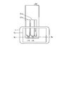
- FIG. 1 is a view showing an example of the overall configuration of a computer 1 according to the present embodiment.
- the computer 1 includes storages 2 a and 2 b, a RAID card (RAID controller card) 3, a main board 10, LEDs (Light Emitting Diodes) 4 a and 4 b, and an LED control board 5.
- the computer 1 further includes a display device such as a display (not shown) and an input device such as a keyboard and a mouse, and has a hardware configuration using a normal computer.
- the computer 1 is an example of a RAID device in the present embodiment.
- the storages 2a and 2b are storage devices such as a hard disk drive (HDD) or a solid state drive (SSD).
- HDD hard disk drive
- SSD solid state drive
- the RAID card 3 is an expansion card attached to the computer 1 and includes a RAID controller 31.
- the RAID controller 31 has a hardware configuration including a control device such as a processor and a storage device such as a flash memory.
- the RAID controller 31 includes an acquisition unit 32, an execution unit 33, a calculation unit 34, a transmission unit 35, and a reception unit 36.
- the functions of the RAID controller 31 may be realized by a software program or may be realized by a hardware circuit.
- the execution unit 33 controls the storage 2 using the RAID 1 technology and executes a rebuilding process.
- the rebuild process is performed by copying data from another non-failed storage 2 to the replaced storage 2 when one of the plurality of storages 2 fails and is replaced with a new storage 2
- the process is to restore the data stored in the failed storage 2.
- the acquisition unit 32 acquires the status information of the storage 2, the rebuilding state, and the address at which the rebuilding process is completed.
- the status information is information indicating whether the status (operating state) of the storage 2 is normal or an abnormality in which a failure or the like has occurred.
- the rebuild state is information indicating whether a rebuild process is being executed in the storage 2.
- the address at which the rebuilding process is completed is an address indicating a storage area in which copying of data from another storage 2 is completed among the storage areas of the newly exchanged storage 2 when the rebuilding process is being executed. .
- the calculating unit 34 calculates the progress degree of the rebuilding process when the rebuilding process is being executed in the storage 2.
- the degree of progress of the rebuilding process is a numerical value indicating the percentage (%) of the address for which the rebuilding process has finished in the entire address space per storage unit 2. It is assumed that the entire address space per storage 2 is registered in advance in a storage unit (not shown) of the RAID controller 31 or the like. Further, in the present embodiment, the progress degree of the rebuilding process is set to the same value in both the storage 2 of the data copy destination and the storage 2 of the copy source.
- the transmitting unit 35 transmits the progress degree of the rebuilding process calculated by the calculating unit 34 to the LED control board 5. Further, when the status information of the storage 2 is abnormal, the transmitting unit 35 transmits to the LED control board 5 that the status information of the storage 2 is abnormal. In addition, the transmitting unit 35 transmits an instruction of reading and writing data to the storage 2 based on an instruction from the main board 10.
- the receiving unit 36 receives an instruction for reading and writing data from the main board 10 to the storage 2.
- the main board 10 is a base on which a central processing unit (CPU) 11, a read only memory (ROM), a random access memory (RAM), and the like are mounted.
- CPU central processing unit
- ROM read only memory
- RAM random access memory
- the LEDs 4 a and 4 b are an example of the light emitting unit in the present embodiment, and are installed in the housing of the computer 1 in a state where light emission can be viewed from the outside.
- the LEDs 4a and 4b are simply referred to as the LED 4 when not particularly distinguished.
- One LED 4 of the present embodiment is provided for each storage 2. The LED 4 is turned on (emitted) or turned off (unlit) under the control of the LED control board 5.
- the LED control board 5 When the rebuilding process is being executed in the storage 2, the LED control board 5 emits the LED 4 associated with the storage 2 being rebuilded in a different manner according to the progress degree of the rebuilding process.
- the LED control board 5 causes the LEDs 4 to emit light in different modes according to the progress of the rebuilding process, thereby displaying the progress of the rebuilding process.
- the LED control board 5 of this embodiment changes the blinking cycle of the LED 4a according to the progress of the rebuilding process of the storage 2a, and changes the blinking cycle of the LED 4b according to the progress of the rebuilding of the storage 2b. Change. Details of the blinking cycle of the LED 4 will be described later.
- the LED control board 5 when the status of the storage 2 is abnormal, the LED control board 5 causes the LED 4 to emit light in a mode different from the case where the rebuilding process is being performed. In the present embodiment, when the status of any of the storages 2 is abnormal, the LED control board 5 turns on the LED 4 associated with the storage 2.
- the power for emitting light from the LED 4 is supplied from the main board 10 to the LED 4 via the LED control board 5, but the means for supplying power is not limited to this.
- FIG. 2 is a view showing an example of the appearance of the computer 1 according to the present embodiment.
- the storage 2a is stored in the drive bay 21a, and the storage 2b is stored in the drive bay 21b.
- the LED 4a is installed near the drive bay 21a, and the LED 4b is installed near the drive bay 21b. In the present embodiment, as one example, the LEDs 4a and 4b are respectively installed below the drive bays 21a and 21b.
- FIG. 3 is a diagram showing an example of the change of the blinking cycle of the LED 4 according to the present embodiment.
- the LED control board 5 of this embodiment changes the flashing cycle in stages so that the lighting time of the LED 4 becomes shorter as the progress degree of the rebuilding process becomes higher. Specifically, the lighting time of the LED 4 is shorter when the degree of progress is “11 to 50%” than when the degree of progress of the rebuilding process is “0 to 10%”. Furthermore, the lighting time of the LED 4 is shorter when the degree of progress is “51 to 99%” than when the degree of progress is “11 to 50%”. Since the rebuilding process ends when the progress degree reaches 100%, the blinking ends, and the LED 4 is turned off (extinguished).
- the change of the blink cycle shown in FIG. 3 is an example, and is not limited to this.
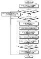
- FIG. 4 is a flowchart illustrating an example of the procedure of calculation processing of the progress degree of rebuild processing according to the present embodiment.
- the RAID controller 31 executes the processing of this flowchart while the computer 1 is in operation.
- the acquisition unit 32 acquires the status information and the rebuild status from each storage 2 (S1).
- the transmitting unit 35 determines whether the statuses of the storages 2a and 2b acquired by the acquiring unit 32 are "normal" (S2).
- the transmitting unit 35 transmits that the status of the storage 2 is "abnormal” to the LED control board 5 (S3) .
- the transmission unit 35 transmits, to the LED control board 5, information for identifying the storage 2 whose status is “abnormal” among the plurality of storages 2.
- the LED control board 5 controls and turns on the LED 4 associated with the storage 2 whose status is “abnormal”.
- the acquiring unit 32 determines whether the storage 2 is under rebuild processing from the rebuild state acquired in the processing of S1 ( S4). If none of the storages 2 is in the process of rebuilding (S4 “No”), the process ends.
- the acquiring unit 32 acquires from the storage 2 an address at which the rebuilding process is completed (S5). Then, the calculation unit 34 calculates the progress degree of the rebuilding process from the entire address space of one storage 2 and the address obtained by the acquiring unit 32 and at the end of the rebuilding process (S6).
- the transmitting unit 35 transmits the calculated progress degree of the rebuilding process to the LED control board 5 (S7).
- the LED control board 5 blinks the LED 4 in a blinking cycle corresponding to the transmitted progress degree of the rebuilding process.
- the transmitting unit 35 determines whether the rebuilding process has ended (S8). If the degree of progress of the rebuilding process is less than 100%, the transmitting unit 35 determines that the rebuilding process has not ended (S8 “No”), and the processes of S5 to S7 are repeated.
- the transmitting unit 35 determines that the rebuilding process has ended (S8 “Yes”), and transmits that the rebuilding process has ended to the LED control board 5 (S9) ). In this case, the LED control board 5 ends the blinking of the LED 4.
- the LED control board 5 controls the LEDs 4 to cause the LEDs 4 to emit light in different modes according to the progress degree of the rebuild process, the degree of progress of the rebuild process Can be easily grasped.
- the computer 1 of the present embodiment blinks the LED 4 during execution of the rebuilding process, and changes the blinking cycle of the LED 4 in accordance with the progress degree of the rebuilding process. Therefore, according to the computer 1 of the present embodiment, the user can easily grasp the presence or absence of the execution of the rebuilding process and the progress degree even from a distant position.
- the computer 1 is an example of a RAID device, but the RAID device may be the RAID card 3 or the RAID controller 31 installed in the RAID card 3.
- the RAID device may be the RAID card 3 or the RAID controller 31 installed in the RAID card 3.
- a configuration provided with a chipset mounted on the main board 10, a dedicated circuit, the CPU 11, or the like may be employed as the function of the RAID controller 31 or the LED control board 5 of the present embodiment.
- the functions of the LED control board 5 of this embodiment may be realized by a software program executed by the CPU 11 or the RAID controller 31.
- the acquisition unit 32 of the computer 1 acquires from the storage 2 whether the rebuild process is being executed or not, for example, the start of the rebuild process received by the reception unit 36 from the main board 10 A configuration may be adopted in which it is determined whether the rebuilding process is being performed based on the signal.
- RAID 1 in which the computer 1 is provided with two storages 2 is taken as an example, but the number of storages 2 and the type of RAID to be applied are not limited to this.
- Modification 1 Although the computer 1 of the first embodiment changes the blinking cycle of the LED 4 according to the progress degree of the rebuilding process, the change of the light emission mode of the LED 4 is not limited to this.
- FIG. 5 is a diagram showing an example of a change in the number of times of blinking per unit time t1 of the LED 4 according to the present modification.
- the LED control board 5 of this modification changes the number of blinks of the LED 4 per predetermined unit time t1 in a stepwise manner in accordance with the progress degree of the rebuilding process.
- the number of times the LED 4 blinks per unit time t1 is larger when the progress degree is “11 to 50%” than when the progress degree of the rebuild processing is “0 to 10%”.
- the number of blinks of the LED 4 per unit time t1 is larger in the case where the degree of progress is “51 to 99%” than in the case where the degree of progress is “11 to 50%”.
- the number of blinks shown in FIG. 5 is an example, and is not limited to this.
- the computer 1 according to the first embodiment indicates the progress of the rebuilding process by the change of the blinking cycle of the LED 4.
- the degree of progress of the rebuilding process is indicated by changing the number of flashing LEDs 4.
- FIG. 6 is a view showing an example of the overall configuration of the computer 201 according to the present embodiment.
- the computer 201 includes storages 2a and 2b, a RAID card 3, a main board 10, LEDs 4c to 4h (light emitting units), and an LED control board 205.
- the storages 2a and 2b, the RAID card 3 and the main board 10 have the same functions as in the first embodiment.
- the LED control board 205 of the present embodiment includes the flashing LED 4 among the plurality of LEDs 4 installed for each storage 2 according to the progress degree of the rebuild processing for each storage 2 in addition to the functions of the first embodiment. By changing the number, the progress of the rebuilding process is displayed. Further, when the status of any storage 2 is abnormal, the LED control board 205 turns on all three LEDs 4 associated with the storage 2 whose status is abnormal.
- FIG. 7 is a view showing an example of a change in the number of blinks of the LED 4 according to the present embodiment.
- the LED control board 205 changes the number of the LEDs 4 to be blinked among the LEDs 4c to 4e according to the progress of the rebuilding process of the storage 2a.
- the LED control board 205 blinks the LED 4c among the LEDs 4c to 4e.
- the LED control board 205 blinks the LED 4 c and the LED 4 d.
- the LED control board 205 blinks all the three LEDs 4c to 4e.
- the number of LEDs 4c to 4e shown in FIG. 7 is an example, and the present invention is not limited to this. Further, the LED control board 205 changes the number of the LEDs 4 to blink among the LEDs 4f to 4h in the same manner as the example shown in FIG. 7 according to the progress degree of the rebuilding process of the storage 2b.
- the procedure of the process executed by the RAID controller 31 according to the present embodiment is the same as the procedure of the first embodiment described in FIG.
- the computer 201 changes the number of flashing LEDs 4 among the plurality of LEDs 4 associated with each storage 2 according to the progress degree of the rebuilding process for each storage 2. For this reason, according to the computer 201 of the present embodiment, the user can grasp the degree of progress from the number of lit LEDs 4, so it does not matter if the LED 4 is continuously viewed and it is better. It can be grasped in a short time.
- the degree of progress of the rebuilding process is indicated by changing the number of flashing LEDs 4.
- a bar graph LED LED level meter in which a plurality of LEDs are arranged in a bar graph shape displays the progress degree of the rebuilding process.
- FIG. 8 is a view showing an example of the entire configuration of a computer 301 according to the present embodiment.
- the computer 301 includes storages 2a and 2b, a RAID card 3, a main board 10, bar graph LEDs 304a and 304b, and an LED control board 305.
- the storages 2a and 2b, the RAID card 3 and the main board 10 have the same functions as in the first embodiment.
- the bar graph LEDs 304a and 304b are light emitting portions in which a plurality of LEDs are linearly arranged to have a bar graph shape.
- the bar graph LED 304 is installed for each storage 2.
- the LED control board 305 displays the progress of the rebuilding process by changing the number of blinking LEDs among the plurality of LEDs included in the bar graph LED 304 according to the progress of the rebuilding for each storage 2. . Further, when the status of any of the storages 2 is abnormal, the LED control board 305 turns on the bar graph LED 304 associated with the storage 2 whose status is abnormal.
- FIG. 9 is a view showing an example of the appearance of the computer 301 according to the present embodiment.
- the bar graph LED 304a is installed in front of the drive bay 21a in which the storage 2a is stored.
- the bar graph LED 304 b is installed in front of the drive bay 21 b in which the storage 2 b is stored.
- the bar graph LEDs 304a and 304b may be located near the drive bays 21a and 21b, respectively, and are not limited to the installation positions shown in FIG.
- FIG. 10 is a diagram showing an example of a change in blinking of the bar graph LED 304 a according to the present embodiment.
- the LEDs included in the hatched portion of the bar graph LED 304 a in FIG. 10 blink, and the LEDs in the other portions are off.
- the LED control board 305 blinks a plurality of LEDs included in the bar graph LED 304a in order from the lower side as the degree of progress of the rebuilding process of the storage 2a becomes higher. Therefore, as the degree of progress of the rebuilding process of the storage 2a becomes higher, the blinking range of the bar graph LED 304a becomes wider.
- the bar graph LED 304 a is taken as an example in FIG. 10, the change of the blinking of the bar graph LED 304 b is the same.
- the procedure of the process executed by the RAID controller 31 according to the present embodiment is the same as the procedure of the first embodiment described in FIG.
- the progress degree of the rebuilding process in each storage 2 can be shown in more detail.
- the bar graph LED 304 displays the progress of the rebuilding process.
- the degree of progress of the rebuilding process is displayed by a circle graph LED in which a plurality of LEDs are arranged in a circle graph.
- FIG. 11 is a diagram showing an example of the overall configuration of a computer 401 according to the present embodiment.
- the computer 401 includes storages 2a and 2b, a RAID card 3, a main board 10, LEDs 414a and 414b, circle graph LEDs 424a and 424b, and an LED control board 405.
- the storages 2a and 2b, the RAID card 3 and the main board 10 have the same functions as in the first embodiment.
- the circle graph LEDs 424a and 424b are light emitting portions in which a plurality of LEDs are arranged in a circle to form a circle graph.
- the pie chart LED 424 is installed for each storage 2.
- the circle graph LED 424 is also referred to as a circle bar graph LED.
- the LEDs 414 a and 414 b are single LEDs, and are located at the centers of the circle LEDs 424 a and 424 b, for example.
- the circle graph LED 424 and the LED 414 are installed near the drive bay 21 in which each storage 2 is stored.
- the LED control board 405 changes the number of blinking LEDs among the plurality of LEDs included in the pie chart LED 424 in accordance with the progress of the rebuilding process for each storage 2. Further, when the status of any of the storages 2 is abnormal, the LED control board 405 turns on the LED 414 associated with the storage 2 whose status is abnormal.
- FIG. 12 is a diagram showing an example of a change in blinking of the circle graph LED 424 a according to the present embodiment.
- the LEDs included in the hatched portion of the circle graph LED 424 a of FIG. 12 blink, and the LEDs in the other portions are off.
- the LED control board 405 blinks the plurality of LEDs included in the circle graph LED 424a in the order of clockwise from the upper center as the progress of the rebuilding process of the storage 2a becomes higher. . For this reason, the higher the degree of progress of the rebuilding process of the storage 2a, the wider the blinking range of the pie chart LED 424a.
- the LED 414a since the status of the storage 2a is normal, the LED 414a is turned off. If the status of the storage 2a is abnormal, the LED control board 405 turns on the LED 414a.
- the circle graph LED 424 a and the LED 414 a are exemplified in FIG. 12, the light emission mode of the circle graph LED 424 b is the same.
- the procedure of the process executed by the RAID controller 31 according to the present embodiment is the same as the procedure of the first embodiment described in FIG.
- the degree of progress of the rebuilding process in each storage 2 can be shown in detail with a small installation area.
- Embodiment 5 In the first to fourth embodiments, the display of the progress degree of the rebuilding process is completed by the processing by the computers 1, 201, 301, and 401, but the display method is not limited to this. In the fifth embodiment, by transmitting the progress of the rebuilding process to another device by visible light communication, it is possible to display the progress on another device.
- FIG. 13 is a view showing an example of the entire configuration of a computer 501 according to the present embodiment.
- the computer 501 includes storages 2a and 2b, a RAID card 3, a main board 10, LEDs 4a and 4b, an LED control board 5, and a modulation circuit 6.
- the storages 2a and 2b, the RAID card 3, the main board 10, the LEDs 4a and 4b, and the LED control board 5 have the same functions as in the first embodiment.
- the modulation circuit 6 modulates the blinking cycle of the LED 4 to a cycle indicating the progress of the rebuilding process for each storage 2 based on the protocol of visible light communication.
- the modulation circuit 6 may be provided on the LED control board 5 or the main board 10. Also, the function of the modulation circuit 6 may be realized by a software program.
- the modulation circuit 6 modulates the blinking cycle, whereby the light output from the LED 4 becomes a signal indicating the numerical value of the degree of progress of the rebuilding process based on the protocol of visible light communication.
- the signal of visible light communication can be read by a device such as a smartphone or a tablet PC (Personal Computer) in which an application for reading data based on the protocol of visible light communication is installed in advance.
- FIG. 14 is a view showing an example of the display of the progress degree of the rebuilding process according to the present embodiment.
- an application for reading visible light communication is installed in the smartphone 7 shown in FIG. 14, an application for reading visible light communication is installed.
- the smartphone 7 reads the progress degree of the rebuilding process for each storage 2 from the light of the LED 4 captured by the camera mounted on the smartphone 7 by the application.
- the smartphone 7 displays the captured image as a background on the display 71, and superimposes the progress degree of the rebuilding process on the displayed captured image.
- the progress of the rebuilding process of the storage 2 a indicated by the light of the LED 4 a and the progress of the rebuilding process of the storage 2 b indicated by the light of the LED 4 b are both “11%”.
- the smartphone 7 displays the value “11%” of the read degree of progress near the LEDs 4 a and 4 b on the image displayed on the display 71.
- the display mode shown in FIG. 14 is an example, and the present invention is not limited to this.
- the procedure of the process executed by the RAID controller 31 according to the present embodiment is the same as the procedure of the first embodiment described in FIG.
- the computer 501 blinks the LED 4 in a cycle that indicates the progress of the rebuilding process based on the protocol of visible light communication, so that the progress of the rebuilding process is displayed on the display 71 such as the smartphone 7 as a percentage It can be displayed with numerical values such as. Therefore, according to the computer 501 of the present embodiment, the user can grasp the progress degree in more detail. Further, according to the computer 501 of the present embodiment, the user can easily grasp the progress of the rebuilding process even at a distance where it is difficult to determine the blinking cycle of the LED 4 with the naked eye if visible light can reach. it can.
- the blinking speed of the LED 4 in visible light communication is high, the LED 4 seems to be continuously lit with the naked eye, but the LED blinks even with the naked eye by reducing the blinking speed. You may employ the structure which can recognize that there is.
- Embodiment 6 in addition to displaying the status of each storage 2 or the progress degree of the rebuilding process by the light emission of the LED 4, the access for each storage 2 is changed by changing the light emission color of the LED 4. Display the frequency.
- the computer 1 includes storages 2a and 2b, a RAID card 3, a main board 10, LEDs 4a and 4b, and an LED control board 5.
- the main board 10 and the storages 2a and 2b have the same functions as in the first embodiment.
- the LED 4 of the present embodiment is a multicolor type LED capable of emitting light in a plurality of different colors in addition to the functions of the first embodiment.
- the LED 4 of this embodiment is a two-color LED capable of emitting red and green light.
- the LED 4 may be an RGB full color LED or the like.
- the RAID card 3 of the present embodiment includes the RAID controller 31 as in the first embodiment. Similar to the first embodiment, the RAID controller 31 includes an acquisition unit 32, an execution unit 33, a calculation unit 34, a transmission unit 35, and a reception unit 36. The acquisition unit 32, the execution unit 33, and the reception unit 36 have the same functions as in the first embodiment.
- the calculation unit 34 of the present embodiment calculates the access frequency for each storage 2.
- the access frequency is the frequency of data read / write (access) executed from the CPU 11 mounted on the main board 10 to the storages 2a and 2b within a predetermined time.
- the calculation unit 34 counts, for each of the storages 2, the number of times of reading and writing of the executed data at predetermined time intervals.
- the calculating unit 34 determines that the access frequency at the predetermined time is “high” when the counted number is the predetermined number or more, and “low” when the counted number is less than the predetermined number. calculate.
- the transmitting unit 35 of the present embodiment transmits the access frequency for each storage 2 calculated by the calculating unit 34 to the LED control board 5 in addition to the functions of the first embodiment.
- the LED control board 5 of the present embodiment causes the LEDs 4 to emit light in different modes according to the access frequency of each storage 2. Specifically, when the access frequency for each storage 2 is “high” during the rebuild process, the LED control board 5 blinks the LED 4 associated with the storage 2 in red. Further, when the access frequency for each storage 2 is “low” during the rebuild processing, the LED control board 5 blinks the LED 4 associated with the storage 2 in green.
- the time until the rebuilding process ends becomes long.
- the time until the rebuilding process may end may be long.
- the LED control board 5 turns on the LED 4 associated with the storage 2 in red.
- the emission color of the LED 4 in the present embodiment is an example, and the present invention is not limited to this.
- FIG. 15 is a flowchart illustrating an example of the procedure of calculation processing of the progress degree of rebuild processing according to the present embodiment.
- the processing from the acquisition of the status information and the rebuild status of the storage 2 in S1 to the transmission of the progress degree of the rebuild processing in S7 is the same as that of the first embodiment.
- the calculating unit 34 calculates the access frequency (“high” or “low”) for each storage 2 ( S61).
- the transmission unit 35 transmits the access frequency for each storage 2 calculated by the calculation unit 34 to the LED control board 5 (S62).
- the LED control board 5 blinks the LED 4 associated with the storage 2 in red.
- the LED control board 5 blinks the LEDs 4 associated with the storage 2 in green.
- the processing from the determination processing of the completion of the rebuilding processing of S8 performed after the processing of S62 to the processing of transmission of the completion of the rebuilding processing of S9 is the same as that of the first embodiment.
- the computer 1 of the present embodiment causes the LED 4 to emit light in a different manner according to the progress degree of the rebuilding process, and further causes the LED 4 to emit light in a different manner according to the access frequency for each storage 2. Therefore, according to the computer 1 of the present embodiment, the user can more accurately estimate the time required to complete the rebuilding process from the access frequency of the storage 2 on which the rebuilding process is being performed and the progress degree of the rebuilding process. can do.
- the user stops the rebuilding process once by grasping that the access frequency of the storage 2 in which the rebuilding process is being executed is high, It can be determined that the rebuilding process is to be performed again after the execution is completed.
- the access frequency is shown in two stages of “high” and “low”, but, for example, a configuration using the number of times of reading and writing for each storage 2 within a predetermined time is used as the value of the access frequency It is good.
- the LED control board 5 adopts a configuration in which the LED 4 blinks in a different color according to the access frequency during the execution of the rebuild process, but the LED 4 may be changed according to the access frequency even during the rebuild process You may employ
- the configuration in which the LED 4 is blinked in a different color according to the access frequency is combined with the configuration of the first embodiment, but the configuration may be combined with the configurations of the second to fifth embodiments. good.
- a RAID apparatus is provided that allows the user to easily grasp the degree of progress of the rebuilding process.
- the calculation program of the progress degree of the rebuilding process executed by the computer 1 of the present embodiment is provided by being incorporated in advance in a ROM or the like. Further, the program for calculating the progress of the rebuilding process executed by the computer 1 according to the present embodiment is a file in an installable format or an executable format, and is a CD-ROM, a flexible disk (FD), a CD-R, a DVD It may be configured to be recorded and provided in a computer-readable recording medium such as a Digital Versatile Disk).
- calculation program of the progress degree of the rebuilding process to be executed by the computer 1 of the present embodiment is stored on a computer connected to a network such as the Internet and configured to be provided by downloading via the network. Also good. Further, the calculation program of the progress degree of the rebuilding process executed by the computer 1 of the present embodiment may be provided or distributed via a network such as the Internet.
- the calculation program of the progress degree of the rebuilding process executed by the computer 1 has a module configuration including the above-described units (acquisition unit, execution unit, calculation unit, transmission unit, reception unit).
- a CPU processor
Landscapes
- Engineering & Computer Science (AREA)
- Theoretical Computer Science (AREA)
- Physics & Mathematics (AREA)
- General Engineering & Computer Science (AREA)
- General Physics & Mathematics (AREA)
- Quality & Reliability (AREA)
- Computing Systems (AREA)
- Human Computer Interaction (AREA)
- Mathematical Physics (AREA)
- Debugging And Monitoring (AREA)
Priority Applications (3)
| Application Number | Priority Date | Filing Date | Title |
|---|---|---|---|
| CN201880087351.7A CN111630489A (zh) | 2018-01-25 | 2018-08-31 | Raid装置 |
| SG11202006785UA SG11202006785UA (en) | 2018-01-25 | 2018-08-31 | Raid device |
| KR1020207021624A KR20200100814A (ko) | 2018-01-25 | 2018-08-31 | Raid 장치 |
Applications Claiming Priority (2)
| Application Number | Priority Date | Filing Date | Title |
|---|---|---|---|
| JP2018-010770 | 2018-01-25 | ||
| JP2018010770A JP2019128841A (ja) | 2018-01-25 | 2018-01-25 | Raid装置 |
Publications (1)
| Publication Number | Publication Date |
|---|---|
| WO2019146148A1 true WO2019146148A1 (ja) | 2019-08-01 |
Family
ID=67395320
Family Applications (1)
| Application Number | Title | Priority Date | Filing Date |
|---|---|---|---|
| PCT/JP2018/032457 Ceased WO2019146148A1 (ja) | 2018-01-25 | 2018-08-31 | Raid装置 |
Country Status (6)
| Country | Link |
|---|---|
| JP (1) | JP2019128841A (https=) |
| KR (1) | KR20200100814A (https=) |
| CN (1) | CN111630489A (https=) |
| SG (1) | SG11202006785UA (https=) |
| TW (1) | TW201933098A (https=) |
| WO (1) | WO2019146148A1 (https=) |
Cited By (1)
| Publication number | Priority date | Publication date | Assignee | Title |
|---|---|---|---|---|
| JP2022171202A (ja) * | 2021-04-30 | 2022-11-11 | 株式会社 ニューテック | 記憶装置およびリビルド方法 |
Families Citing this family (1)
| Publication number | Priority date | Publication date | Assignee | Title |
|---|---|---|---|---|
| JP2021182268A (ja) * | 2020-05-19 | 2021-11-25 | Necプラットフォームズ株式会社 | コントローラ、情報処理装置、情報処理方法及びプログラム |
Citations (4)
| Publication number | Priority date | Publication date | Assignee | Title |
|---|---|---|---|---|
| CN102520880A (zh) * | 2011-12-01 | 2012-06-27 | 浪潮电子信息产业股份有限公司 | 一种系统raid管理模块设计方法 |
| US20150100298A1 (en) * | 2013-10-07 | 2015-04-09 | American Megatrends, Inc. | Techniques for validating functionality of backplane controller chips |
| WO2015073042A1 (en) * | 2013-11-18 | 2015-05-21 | Hewlett-Packard Development Company, L.P. | Indicating rebuild state of storage devices |
| WO2016170662A1 (ja) * | 2015-04-23 | 2016-10-27 | 株式会社フィックスターズ | 高速データ伝送が可能な記憶装置、そのためのプログラムおよびアダプタ |
Family Cites Families (4)
| Publication number | Priority date | Publication date | Assignee | Title |
|---|---|---|---|---|
| US7028213B2 (en) * | 2001-09-28 | 2006-04-11 | Hewlett-Packard Development Company, L.P. | Error indication in a raid memory system |
| JP5891890B2 (ja) | 2012-03-26 | 2016-03-23 | 富士通株式会社 | ストレージシステム、ストレージ装置およびデータ復元方法 |
| JP5913078B2 (ja) | 2012-12-21 | 2016-04-27 | 株式会社 日立産業制御ソリューションズ | ディスクアレイシステム、データ復旧方法、および、データ復旧プログラム |
| JP6142576B2 (ja) | 2013-03-04 | 2017-06-07 | 日本電気株式会社 | ストレージ制御装置、ストレージ装置およびストレージ制御方法 |
-
2018
- 2018-01-25 JP JP2018010770A patent/JP2019128841A/ja active Pending
- 2018-08-31 KR KR1020207021624A patent/KR20200100814A/ko not_active Withdrawn
- 2018-08-31 SG SG11202006785UA patent/SG11202006785UA/en unknown
- 2018-08-31 CN CN201880087351.7A patent/CN111630489A/zh not_active Withdrawn
- 2018-08-31 WO PCT/JP2018/032457 patent/WO2019146148A1/ja not_active Ceased
- 2018-09-05 TW TW107131110A patent/TW201933098A/zh unknown
Patent Citations (4)
| Publication number | Priority date | Publication date | Assignee | Title |
|---|---|---|---|---|
| CN102520880A (zh) * | 2011-12-01 | 2012-06-27 | 浪潮电子信息产业股份有限公司 | 一种系统raid管理模块设计方法 |
| US20150100298A1 (en) * | 2013-10-07 | 2015-04-09 | American Megatrends, Inc. | Techniques for validating functionality of backplane controller chips |
| WO2015073042A1 (en) * | 2013-11-18 | 2015-05-21 | Hewlett-Packard Development Company, L.P. | Indicating rebuild state of storage devices |
| WO2016170662A1 (ja) * | 2015-04-23 | 2016-10-27 | 株式会社フィックスターズ | 高速データ伝送が可能な記憶装置、そのためのプログラムおよびアダプタ |
Cited By (2)
| Publication number | Priority date | Publication date | Assignee | Title |
|---|---|---|---|---|
| JP2022171202A (ja) * | 2021-04-30 | 2022-11-11 | 株式会社 ニューテック | 記憶装置およびリビルド方法 |
| JP7352300B2 (ja) | 2021-04-30 | 2023-09-28 | 株式会社 ニューテック | 記憶装置およびリビルド方法 |
Also Published As
| Publication number | Publication date |
|---|---|
| KR20200100814A (ko) | 2020-08-26 |
| CN111630489A (zh) | 2020-09-04 |
| TW201933098A (zh) | 2019-08-16 |
| SG11202006785UA (en) | 2020-08-28 |
| JP2019128841A (ja) | 2019-08-01 |
Similar Documents
| Publication | Publication Date | Title |
|---|---|---|
| US9713215B2 (en) | Identification of storage device for trouble shooting | |
| JP4983915B2 (ja) | 制御プログラム、制御装置および制御方法 | |
| US10719380B2 (en) | Operation management apparatus, operation management method, and storage medium | |
| US20120133520A1 (en) | Computer chassis system and hard disk status display method thereof | |
| CN104516802A (zh) | 一种指示不同类型硬盘的状态的方法及系统 | |
| TW201717012A (zh) | 指示燈控制系統以及發光二極體控制方法 | |
| US8099634B2 (en) | Autonomic component service state management for a multiple function component | |
| CN103645981A (zh) | 硬盘识别方法和系统 | |
| CN107015890A (zh) | 存储设备、具有其的服务器系统以及其操作方法 | |
| US20170185355A1 (en) | Method of determining a physical location of a hard drive in a cluster storage system | |
| WO2019146148A1 (ja) | Raid装置 | |
| TWI672587B (zh) | 發光控制系統及方法 | |
| TWI467368B (zh) | 驅動機載架光源控制技術 | |
| US8082368B2 (en) | Display device for indicating connection statuses of a communication channel provided between two systems and method thereof | |
| JP2021529393A (ja) | ストレージシステム及びストレージシステムの稼働モードを切り替えるための方法 | |
| CN102479140A (zh) | 计算机系统及其硬盘状态显示方法 | |
| CN102376338B (zh) | 硬盘模块 | |
| CN107765993B (zh) | 硬盘界面装置 | |
| TW202008165A (zh) | 備援方法及備援系統 | |
| US11531621B2 (en) | Selective endpoint isolation for self-healing in a cache and memory coherent system | |
| CN108319540B (zh) | 硬盘灯号控制系统 | |
| US8977892B2 (en) | Disk control apparatus, method of detecting failure of disk apparatus, and recording medium for disk diagnosis program | |
| TWI587130B (zh) | 硬碟燈號控制系統 | |
| US9865143B2 (en) | Status displaying device and method thereof for solid-state drive | |
| TW202022613A (zh) | 伺服器硬碟指示燈控制系統及其控制方法 |
Legal Events
| Date | Code | Title | Description |
|---|---|---|---|
| 121 | Ep: the epo has been informed by wipo that ep was designated in this application |
Ref document number: 18901888 Country of ref document: EP Kind code of ref document: A1 |
|
| ENP | Entry into the national phase |
Ref document number: 20207021624 Country of ref document: KR Kind code of ref document: A |
|
| NENP | Non-entry into the national phase |
Ref country code: DE |
|
| 122 | Ep: pct application non-entry in european phase |
Ref document number: 18901888 Country of ref document: EP Kind code of ref document: A1 |