WO2019142919A1 - Dispositif de réfrigération cyclone, unité de récupération de froid/ chaleur cyclone, et système de pompe à chaleur équipé dudit dispositif de réfrigération cyclone ou unité de récupération de froid/chaleur cyclone - Google Patents
Dispositif de réfrigération cyclone, unité de récupération de froid/ chaleur cyclone, et système de pompe à chaleur équipé dudit dispositif de réfrigération cyclone ou unité de récupération de froid/chaleur cyclone Download PDFInfo
- Publication number
- WO2019142919A1 WO2019142919A1 PCT/JP2019/001499 JP2019001499W WO2019142919A1 WO 2019142919 A1 WO2019142919 A1 WO 2019142919A1 JP 2019001499 W JP2019001499 W JP 2019001499W WO 2019142919 A1 WO2019142919 A1 WO 2019142919A1
- Authority
- WO
- WIPO (PCT)
- Prior art keywords
- refrigerant
- phase refrigerant
- fluid
- cavity
- cooled
- Prior art date
Links
Images


Classifications
-
- F—MECHANICAL ENGINEERING; LIGHTING; HEATING; WEAPONS; BLASTING
- F25—REFRIGERATION OR COOLING; COMBINED HEATING AND REFRIGERATION SYSTEMS; HEAT PUMP SYSTEMS; MANUFACTURE OR STORAGE OF ICE; LIQUEFACTION SOLIDIFICATION OF GASES
- F25D—REFRIGERATORS; COLD ROOMS; ICE-BOXES; COOLING OR FREEZING APPARATUS NOT OTHERWISE PROVIDED FOR
- F25D3/00—Devices using other cold materials; Devices using cold-storage bodies
- F25D3/12—Devices using other cold materials; Devices using cold-storage bodies using solidified gases, e.g. carbon-dioxide snow
-
- F—MECHANICAL ENGINEERING; LIGHTING; HEATING; WEAPONS; BLASTING
- F25—REFRIGERATION OR COOLING; COMBINED HEATING AND REFRIGERATION SYSTEMS; HEAT PUMP SYSTEMS; MANUFACTURE OR STORAGE OF ICE; LIQUEFACTION SOLIDIFICATION OF GASES
- F25B—REFRIGERATION MACHINES, PLANTS OR SYSTEMS; COMBINED HEATING AND REFRIGERATION SYSTEMS; HEAT PUMP SYSTEMS
- F25B39/00—Evaporators; Condensers
- F25B39/02—Evaporators
-
- F—MECHANICAL ENGINEERING; LIGHTING; HEATING; WEAPONS; BLASTING
- F25—REFRIGERATION OR COOLING; COMBINED HEATING AND REFRIGERATION SYSTEMS; HEAT PUMP SYSTEMS; MANUFACTURE OR STORAGE OF ICE; LIQUEFACTION SOLIDIFICATION OF GASES
- F25B—REFRIGERATION MACHINES, PLANTS OR SYSTEMS; COMBINED HEATING AND REFRIGERATION SYSTEMS; HEAT PUMP SYSTEMS
- F25B7/00—Compression machines, plants or systems, with cascade operation, i.e. with two or more circuits, the heat from the condenser of one circuit being absorbed by the evaporator of the next circuit
-
- F—MECHANICAL ENGINEERING; LIGHTING; HEATING; WEAPONS; BLASTING
- F25—REFRIGERATION OR COOLING; COMBINED HEATING AND REFRIGERATION SYSTEMS; HEAT PUMP SYSTEMS; MANUFACTURE OR STORAGE OF ICE; LIQUEFACTION SOLIDIFICATION OF GASES
- F25B—REFRIGERATION MACHINES, PLANTS OR SYSTEMS; COMBINED HEATING AND REFRIGERATION SYSTEMS; HEAT PUMP SYSTEMS
- F25B9/00—Compression machines, plants or systems, in which the refrigerant is air or other gas of low boiling point
- F25B9/002—Compression machines, plants or systems, in which the refrigerant is air or other gas of low boiling point characterised by the refrigerant
- F25B9/008—Compression machines, plants or systems, in which the refrigerant is air or other gas of low boiling point characterised by the refrigerant the refrigerant being carbon dioxide
-
- F—MECHANICAL ENGINEERING; LIGHTING; HEATING; WEAPONS; BLASTING
- F25—REFRIGERATION OR COOLING; COMBINED HEATING AND REFRIGERATION SYSTEMS; HEAT PUMP SYSTEMS; MANUFACTURE OR STORAGE OF ICE; LIQUEFACTION SOLIDIFICATION OF GASES
- F25B—REFRIGERATION MACHINES, PLANTS OR SYSTEMS; COMBINED HEATING AND REFRIGERATION SYSTEMS; HEAT PUMP SYSTEMS
- F25B9/00—Compression machines, plants or systems, in which the refrigerant is air or other gas of low boiling point
- F25B9/02—Compression machines, plants or systems, in which the refrigerant is air or other gas of low boiling point using Joule-Thompson effect; using vortex effect
- F25B9/04—Compression machines, plants or systems, in which the refrigerant is air or other gas of low boiling point using Joule-Thompson effect; using vortex effect using vortex effect
-
- F—MECHANICAL ENGINEERING; LIGHTING; HEATING; WEAPONS; BLASTING
- F25—REFRIGERATION OR COOLING; COMBINED HEATING AND REFRIGERATION SYSTEMS; HEAT PUMP SYSTEMS; MANUFACTURE OR STORAGE OF ICE; LIQUEFACTION SOLIDIFICATION OF GASES
- F25B—REFRIGERATION MACHINES, PLANTS OR SYSTEMS; COMBINED HEATING AND REFRIGERATION SYSTEMS; HEAT PUMP SYSTEMS
- F25B5/00—Compression machines, plants or systems, with several evaporator circuits, e.g. for varying refrigerating capacity
- F25B5/02—Compression machines, plants or systems, with several evaporator circuits, e.g. for varying refrigerating capacity arranged in parallel
-
- F—MECHANICAL ENGINEERING; LIGHTING; HEATING; WEAPONS; BLASTING
- F25—REFRIGERATION OR COOLING; COMBINED HEATING AND REFRIGERATION SYSTEMS; HEAT PUMP SYSTEMS; MANUFACTURE OR STORAGE OF ICE; LIQUEFACTION SOLIDIFICATION OF GASES
- F25B—REFRIGERATION MACHINES, PLANTS OR SYSTEMS; COMBINED HEATING AND REFRIGERATION SYSTEMS; HEAT PUMP SYSTEMS
- F25B6/00—Compression machines, plants or systems, with several condenser circuits
- F25B6/04—Compression machines, plants or systems, with several condenser circuits arranged in series
-
- F—MECHANICAL ENGINEERING; LIGHTING; HEATING; WEAPONS; BLASTING
- F25—REFRIGERATION OR COOLING; COMBINED HEATING AND REFRIGERATION SYSTEMS; HEAT PUMP SYSTEMS; MANUFACTURE OR STORAGE OF ICE; LIQUEFACTION SOLIDIFICATION OF GASES
- F25D—REFRIGERATORS; COLD ROOMS; ICE-BOXES; COOLING OR FREEZING APPARATUS NOT OTHERWISE PROVIDED FOR
- F25D17/00—Arrangements for circulating cooling fluids; Arrangements for circulating gas, e.g. air, within refrigerated spaces
- F25D17/02—Arrangements for circulating cooling fluids; Arrangements for circulating gas, e.g. air, within refrigerated spaces for circulating liquids, e.g. brine
-
- F—MECHANICAL ENGINEERING; LIGHTING; HEATING; WEAPONS; BLASTING
- F25—REFRIGERATION OR COOLING; COMBINED HEATING AND REFRIGERATION SYSTEMS; HEAT PUMP SYSTEMS; MANUFACTURE OR STORAGE OF ICE; LIQUEFACTION SOLIDIFICATION OF GASES
- F25D—REFRIGERATORS; COLD ROOMS; ICE-BOXES; COOLING OR FREEZING APPARATUS NOT OTHERWISE PROVIDED FOR
- F25D3/00—Devices using other cold materials; Devices using cold-storage bodies
- F25D3/10—Devices using other cold materials; Devices using cold-storage bodies using liquefied gases, e.g. liquid air
Definitions
- the present invention relates to a cyclone-type refrigerator, a cyclone-type cold heat recovery unit, and a heat pump system provided with the cyclone-type refrigerator or the cyclone-type cold heat recovery unit.
- This type of refrigeration apparatus includes, for example, a compressor that compresses CO 2 to a saturation pressure or a supercritical pressure at a temperature at ordinary temperature level, a condenser that cools and condenses high-pressure gas phase CO 2 from the compressor, and a condenser pressures up the triple point of the CO 2 condensed CO 2 by vessel, solid-gas two-phase is a mixture of phases solid under reduced pressure to a temperature level CO 2 (dry ice) and vapor phase CO 2 (carbon dioxide) and CO 2 expansion device to CO 2, the cold due to sublimation of the solid-gas two-phase CO 2 fed from CO 2 expansion device, a gas-phase CO 2 after sublimation is supplied to the fluid to be cooled from the cooling load
- a CO 2 sublimation means to be sent to a compressor is provided (see, for example, Patent Document 1).
- the CO 2 sublimation means comprises a direct contact CO 2 sublimation device (see FIG. 1 of Patent Document 1) or an indirect contact CO 2 sublimation device (see FIG. 2 of Patent Document 1). Then, in the direct contact CO 2 sublimation apparatus, the solid-gas two-phase CO 2 supplied from the CO 2 expander is ejected into the brine stored in the storage tank, and the solid-gas two-phase CO 2 is brine The submersion heat is used to sublime, the sublimation cools the brine, and the cooled brine exchanges heat with the cooled fluid from the cooling load in the brine heat exchanger.
- the fluid to be cooled from the cooling load is made to flow into a large number of cooling pipes arranged in parallel, while the CO 2 expansion device is provided in the CO 2 passage provided between the cooling pipes.
- the solid-gas two-phase CO 2 fed from the source is allowed to flow, and the solid-gas two-phase CO 2 is sublimated by the heat of the fluid to be cooled in the cooling pipe, and the sublimation cools the fluid to be cooled to cryogenic temperature.
- this refrigeration system utilizes the latent heat of solid phase CO 2 in the solid-gas two-phase state, and also has a defect that the cooling capacity is inferior as compared to the case where the sublimation heat of only solid phase CO 2 is used. there were.
- an object of the present invention is to provide a refrigeration system which has a high cooling capacity and can be operated smoothly and continuously.
- the present invention has a cylindrical part which is extended vertically and closed at the upper end opening, and a diameter smaller than that of the cylindrical part, connected to the upper end of the cylindrical part and directed upward from the upper end And an exhaust pipe communicating with the internal space of the cylindrical part, and a cooling part having a cavity connected to the lower end of the cylindrical part and communicating with the internal space of the cylindrical part.
- a refrigerant inlet is formed on the upper side wall of the cylindrical portion, and one end is connected to the refrigerant inlet, and the other end receives a supply of liquid phase refrigerant condensed under high pressure from the other end.
- a decompressor provided in the refrigerant inflow pipe, wherein the liquid phase refrigerant supplied to the refrigerant inflow pipe is decompressed by the decompressor to form a solid-gas two-phase refrigerant;
- Phase refrigerant flows into the internal space of the cylindrical portion and While forming the vortex which descends in the internal space, it is separated into a solid-phase refrigerant and a gas-phase refrigerant, and while the solid-phase refrigerant is deposited in the cavity, the gas-phase refrigerant descends from the bottom of the cavity It forms a vortex that rises through the inner space of the vortex, and flows out from the exhaust pipe, and further extends through the cavity of the cooling unit, and both ends of each other outside the cooling unit.
- the solid-phase refrigerant which is connected and provided in a portion in the cavity in the cooled fluid circulation pipeline through which the cooled fluid from the cooling load flows and the cooled fluid circulation pipeline and the solid phase refrigerant deposited in the cavity
- Kron refrigeration device is provided.
- the heat exchanger is formed of a heat conductor, and comprises a container having a fluid outlet and a fluid inlet, the container being filled with the fluid to be cooled therein;
- a fluid circulation line is connected to the fluid outlet of the container at one end, and a fluid discharge line for cooling which protrudes from the container to the outside of the cooling unit through the cavity, and the fluid at the one end of the container.
- the cooling fluid supply line connected to the inlet and projecting from the container through the cavity to the outside of the cooling unit, and the other end of the cooling fluid discharge line and the cooling fluid supply line
- the other ends of the paths are connected to each other via the cooling load, and the pump is provided in the cooled fluid discharge pipeline or the cooled fluid supply pipeline.
- the cyclonic refrigeration apparatus further comprises an eddy current control member which is disposed straddling the internal space of the cylindrical portion and the cavity of the cooling portion and extends vertically.
- An eddy current control body is connected to a cylindrical lower portion, an upper end surface of the lower portion, and a truncated conical intermediate portion extending upward from the lower portion and an upper end surface of the intermediate portion, and is directed upward from the intermediate portion
- An axial through-hole through which the rising vortex flows is formed in the interior of the vortex control body, and the through-hole has a circular cross section, and the vortex has After being tapered upward from the bottom surface of the control body, the vortex flow control body is extended to the upper end surface of the eddy current control body, and the eddy current control body is coaxial with the cylindrical portion and constant on the lower side of the bottom surface.
- Space is open In a state, the lower is located within said cavity such that said intermediate portion is located across the cavity and the inner space, is supported by the cooling unit or
- the internal space of the cylindrical portion is tapered downward.
- the refrigerant is carbon dioxide or water or ammonia.
- a cyclone type refrigeration system as described above, an outlet of the exhaust pipe of the cyclone type refrigeration system, and a refrigerant circulation pipe connecting the other end of the refrigerant inflow pipe
- a compressor disposed in the refrigerant circulation pipeline and configured to compress the gas phase refrigerant discharged from the exhaust pipe of the cyclone type refrigeration system, and disposed downstream of the compressor in the refrigerant circulation pipeline;
- a heat pump system is provided, comprising: a condenser that condenses the gas phase refrigerant compressed by the compressor to form the liquid phase refrigerant.
- a cyclone type refrigeration system as described above, an outlet of the exhaust pipe of the cyclone type refrigeration system, and a refrigerant circulation pipe connecting the other end of the refrigerant inflow pipe
- a compressor disposed in the refrigerant circulation pipeline and configured to compress the gas phase refrigerant discharged from the exhaust pipe of the cyclone type refrigeration system, and disposed in series downstream of the compressor in the refrigerant circulation pipeline
- First and second condensers that condense the gas-phase refrigerant compressed by the compressor to form the liquid-phase refrigerant, and the first and second condensers in the refrigerant circulation pipeline
- Another heat exchanger disposed downstream, a bypass line connecting the downstream side of the other heat exchanger in the refrigerant circulation line and the upstream side of the compressor, and the bypass line
- Another pressure reducer An evaporator disposed downstream of the another pressure reducer in the bypass line, and a downstream side of the connection point in the refrigerant circulation line and an upstream side
- a third flow controller disposed upstream of a connection point between the first and second flow controllers and the downstream end of the bypass channel in the refrigerant circulation pipeline, and the third flow controller in the bypass channel
- a cyclone type cold heat recovery unit is provided, characterized by comprising a fourth flow rate controller disposed downstream of the evaporator.
- a cascade heat pump system comprising a low side cycle and a high side cycle, wherein the low side cycle comprises the above-mentioned cyclone type cold heat recovery unit.
- a cascaded heat pump system is provided, characterized in that the further heat exchanger of the cyclone type cold heat recovery unit forms a lower side heat exchanger of a cascaded heat exchanger.
- the high-temperature side heat forming the cascade heat exchanger as a pair with the other heat exchanger of the cyclone type cold heat recovery unit An exchanger, a high-end refrigerant circulation pipeline extending between an outlet and an inlet of the high-end heat exchanger, and a high-temperature refrigerant circulation pipeline disposed downstream of the high-end heat exchanger
- another pressure reducer disposed downstream of the third and fourth condensers.
- the solid-gas two-phase refrigerant formed by depressurizing the liquid-phase refrigerant condensed under high pressure flows into the internal space of the cylindrical portion to form a downward swirling flow of the solid-gas two-phase refrigerant.
- the solid-gas two-phase refrigerant is separated into the solid phase refrigerant and the gas phase refrigerant, and the solid phase refrigerant is collected in the cavity of the cooling unit, while the gas phase refrigerant flows through the inner space of the descending vortex ( Since the exhaust pipe is discharged to the outside, it is possible to prevent the solid phase refrigerant from adhering to and accumulating in the refrigerant flow path during the operation of the refrigeration system and the refrigerant flow path being blocked.
- the fluid to be cooled is returned to the cooled fluid circulation pipeline so as to exchange heat with the solid phase refrigerant deposited in the cavity, and the flow path of the fluid to be cooled is separated from the solid phase refrigerant.
- the solid phase refrigerant adheres to and accumulates in the flow path of the fluid to be cooled and the flow path of the fluid to be cooled is blocked. This enables smooth continuous operation of the refrigeration system.
- the present invention only the solid-phase refrigerant separated from the solid-gas two-phase refrigerant exchanges heat with the fluid to be cooled, and cold heat by sublimation of the solid-phase refrigerant is supplied to the fluid to be cooled. Since all of the heat of sublimation can be used to cool the fluid to be cooled, the cooling capacity is increased as compared to the cooling of the fluid to be cooled using the latent heat of the solid phase refrigerant in the solid-gas two-phase state as in the prior art.
- FIG. 1 shows schematic structure of the cyclone type freezing apparatus by another Example of this invention.
- FIG. 4 shows schematic structure of the heat pump system with which the cyclone type freezing apparatus of FIG. 1 was integrated as an evaporator.
- FIG. 4 is a Mollier diagram in the case where the heat pump system of FIG. 3 is provided with the cyclone type refrigerator of FIG. 2 instead of the cyclone type refrigerator of FIG. 1 and CO 2 is used as a refrigerant.
- the heat pump system of Figure 3 comprises a known evaporator in place of the cyclone-type cooling unit is a Mollier diagram in the case of using CO 2 as the refrigerant. It is a figure which shows schematic structure of the cyclone type cold heat recovery unit provided with the cyclone type freezing apparatus of FIG. It is a figure which shows schematic structure of the cascade heat pump system in which the cyclone type cold heat recovery unit of FIG. 7 was integrated as a low side cycle.
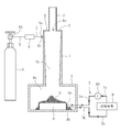
- FIG. 1 is a front view showing a schematic configuration of a cyclone type refrigerating apparatus according to an embodiment of the present invention.
- the cylindrical portion 1 extending up and down, the inner flange 2 provided at the upper end opening 1 a of the cylindrical portion 1, and the outer diameter corresponding to the opening diameter of the inner flange 2
- the exhaust pipe 3 is connected to the inner flange 2 at one end and protrudes upward from the upper end opening 1 a of the cylindrical portion 1.
- the configuration of the connecting portion between the cylindrical portion 1 and the exhaust pipe 3 is not limited to this embodiment.
- the cylindrical portion 1 extends vertically and the upper end opening is closed, and the exhaust pipe 3 having a diameter smaller than that of the cylindrical portion 1 is cylindrical. Any configuration may be employed as long as it is connected to the upper end of the portion 1 and coaxially extends upward from the upper end coaxially with the cylindrical portion 1.
- the inner space 1b of the cylindrical portion 1 is formed to be tapered downward (the inner diameter gradually decreases), but the inner diameter of the inner space 1b may be constant. Further, at the lower end of the cylindrical portion 1, a cooling portion 4 having a cavity 4 a communicating with the internal space 1 b of the cylindrical portion 1 is connected.
- a refrigerant inlet 1 c is formed on the upper side wall of the cylindrical portion 1.
- the refrigerant inlet 1 c preferably extends tangentially to the cross section of the cylindrical portion 1.
- one end 5 a of the refrigerant inflow pipe 5 is connected to the refrigerant inflow port 1 c of the cylindrical portion 1.
- the refrigerant inflow pipe 5 receives the supply of the liquid phase refrigerant condensed under high pressure from the other end 5b.
- An expansion valve (depressurizer) 6 is provided in the refrigerant inflow pipe 5.
- a cylinder G is connected to the other end 5b of the refrigerant inflow pipe 5 as a supply source of liquid phase refrigerant.
- the liquid-phase refrigerant supplied to the refrigerant inflow pipe 5 is decompressed by the expansion valve 6 to form a solid-gas two-phase refrigerant, and the solid-gas two-phase refrigerant flows from the refrigerant inlet 1c of the cylindrical portion 1 to the internal space 1b. It flows in and forms an eddy current by flowing along the inner wall surface of the inner space 1b.
- the pressure outside the vortex is larger than the pressure inside the vortex, and the pressure difference between the outside and the inside of the vortex decreases from the top to the bottom of the internal space 1b.
- the vortex flows from the refrigerant inlet 1 c of the cylindrical portion 1 to the cavity 4 a of the cooling portion 4 and is maintained as it is.
- the solid-gas two-phase refrigerant is separated into the solid phase refrigerant S and the gas phase refrigerant, and the solid phase refrigerant S is deposited in the cavity 4a.
- the gas phase refrigerant reaches the bottom of the cavity 4a, but at this time, since the pressure difference between the outside and the inside of the swirl is small, the gas phase refrigerant forms a rising swirl through the inner space of the falling swirl, It flows out through the pipe 3.
- the refrigerant used in the present invention must be able to be maintained at the pressure and temperature level below the triple point inside the cyclone type refrigerator, and this condition
- the refrigerant that satisfies the above may include carbon dioxide (CO 2 ), water, and ammonia.
- a cooled fluid circulation pipeline extending through the cavity 4a of the cooling unit 4 and having both ends connected to each other outside the cooling unit 4 and in which the cooled fluid from the cooling load 9 flows
- a heat exchanger 8 provided in a portion in the cavity 4a of the to-be-cooled fluid circulation pipeline 7 for exchanging heat between the solid phase refrigerant S deposited in the cavity 4a and the to-be-cooled fluid.
- the heat exchanger 8 is formed of a heat conductor, and comprises a container having a fluid outlet 8a and a fluid inlet 8b and internally filled with a fluid to be cooled.
- antifreeze liquid, ethanol or the like can be used as the fluid to be cooled
- the container (heat exchanger) 8 has high thermal conductivity and is a metal that is not easily affected by corrosion or the like by the fluid to be cooled
- one end of the to-be-cooled fluid circulation pipeline 7 is connected to the fluid outlet 8 a of the container (heat exchanger) 8 and protrudes from the container (heat exchanger) 8 through the cavity 4 a to the outside of the cooling unit 4
- a cooled fluid discharge pipeline 7a and one end thereof are connected to a fluid inlet 8b of a container (heat exchanger) 8 so as to project from the container (heat exchanger) 8 through the cavity 4a to the outside of the cooling unit 4
- the other end of the fluid discharge conduit 7 a and the other end of the fluid supply conduit 7 b are connected to each other via the cooling load 9.
- the pump 10 is further provided in the cooled fluid discharge conduit 7a or the cooled fluid supply conduit 7b, and the operation of the pump 10 causes the fluid to be cooled to flow from the container (heat exchanger) 8 to
- the cooling fluid discharge pipeline 7 a ⁇ the cooling load 9 ⁇ the cooled fluid supply pipeline 7 b ⁇ the vessel (heat exchanger) 8 is refluxed in this order.
- the solid-gas two-phase refrigerant formed by pressure reduction of the liquid phase refrigerant flows into the internal space 1a of the cylindrical portion 1 to form a vortex flowing downward and
- the refrigerant S and the gas phase refrigerant are separated, and the solid phase refrigerant S is deposited in the cavity 4 a of the cooling unit 4, while the gas phase refrigerant forms a swirling flow rising through the inner space of the falling swirling flow. Flow out to the outside.
- the solid-phase refrigerant S deposited in the cavity 4 a is sublimated by the heat of the fluid to be cooled filled in the container (heat exchanger) 8, and the cold heat due to the sublimation is supplied to the fluid to be cooled, and cooled
- the fluid is delivered to the cooling load 9 through the cooled fluid discharge line 7a.
- the downward vortex of the solid-gas two-phase refrigerant is generated in the internal space 1b of the cylindrical portion 1 to separate the solid-gas two-phase refrigerant into the solid-phase refrigerant S and the gas-phase refrigerant and cool the solid-phase refrigerant S Since the gas phase refrigerant is discharged from the exhaust pipe 3 to the outside through the inner space of the downward vortex flow while being collected in the cavity 4a of the part 4, the solid phase refrigerant S adheres to the inside of the refrigerant channel during operation of the refrigeration system It is prevented that it accumulates and a refrigerant
- the fluid to be cooled exchanges heat with the solid phase refrigerant S deposited in the cavity 4 a while refluxing the inside of the fluid circulation pipeline to be cooled, whereby the flow path of the fluid to be cooled is separated from the solid phase refrigerant S Therefore, it is also prevented that the solid phase refrigerant S adheres and accumulates in the flow path of the fluid to be cooled and the flow path of the fluid to be cooled is blocked during operation of the refrigeration device, whereby smooth continuity of the refrigeration device It becomes possible to drive.
- the solid-phase refrigerant S separated from the solid-gas two-phase refrigerant is subjected to heat exchange with the fluid to be cooled, and cold heat due to sublimation of the solid-phase refrigerant S is supplied to the fluid to be cooled. All can be used to cool the fluid being cooled. Therefore, as compared with the conventional example, the solid-gas two-phase refrigerant is subjected to heat exchange with the fluid to be cooled, and the latent heat of the solid-phase refrigerant S in the solid-gas two-phase state is used to cool the fluid to be cooled. Cooling capacity is improved.
- FIG. 2 is a view similar to FIG. 1 showing a schematic configuration of a cyclonic refrigeration apparatus according to another embodiment of the present invention.
- the embodiment of FIG. 2 differs from the embodiment of FIG. 1 only in that a structure for controlling the vortex flow is provided over the internal space 1 b of the cylindrical portion 1 and the cavity 4 a of the cooling portion 4. Therefore, in FIG. 2, the same components as those shown in FIG. 1 are denoted by the same reference numerals, and the detailed description thereof will be omitted below.
- an eddy current control body 11 is disposed straddling the internal space 1 b of the cylindrical portion 1 and the cavity 4 a of the cooling portion 4 and extends vertically.
- the eddy current control body 11 is connected to the cylindrical lower portion 11a and the upper end surface of the lower portion 11a, and is connected to the upper end surface of the intermediate portion 11b and the truncated cone-like intermediate portion 11b extending upward from the lower portion 11a. It consists of a cylindrical upper portion 11c extending upward from 11b.
- the vortex control body 11 has therein an axial through hole 12 through which a rising vortex of gas-phase refrigerant flows.
- the through hole 12 has a circular cross section, and extends upward from the bottom surface 11 e of the eddy current control body 11 in a tapered shape, and then extends up to the upper end surface 11 d of the eddy current control body 11.
- the through hole 12 has a diffuser function.
- the lower portion 11a is located in the cavity 4a of the cooling portion 4 and the middle portion 11b is a cavity in a state where a constant space is opened coaxially with the cylindrical portion 1 and below the bottom surface 11e. It is supported by the cooling unit 4 and / or the cylindrical portion 1 by suitable support members (not shown) so as to be located across the internal space 1b of the cylindrical portion 1 and 4a.
- the falling vortex of the solid-gas two-phase refrigerant passes through the outside of the vortex control body 11, and the rising vortex of the gas-phase refrigerant separated from the solid-gas two-phase refrigerant passes through the through hole 12 of the vortex control body 11. And the pressure is boosted by the diffuser function of the through hole 12 during passage.
- the vortex control body 11 by providing the vortex control body 11, the movement of the gas phase refrigerant in the falling vortex in the lower part of the internal space 1b and the cavity 4a is promoted to the inside of the vortex, and further, the gas phase refrigerant A steady and strong upward vortex is formed.
- the collection efficiency of the solid-phase refrigerant S is higher than that of the embodiment of FIG. 1, and as a result, the cooling performance of the refrigeration system is also improved.
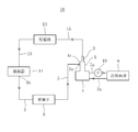
- FIG. 3 is a view showing a schematic configuration of a heat pump system in which the cyclone type refrigeration system of FIG. 1 is incorporated as an evaporator.
- the same components as those shown in FIG. 1 are designated by the same reference numerals, and the detailed description thereof will be omitted below.
- the heat pump system 16 is a refrigerant circulation pipe connecting the cyclone type refrigeration system shown in FIG. 1, the opening of the exhaust pipe 3 of the cyclone type refrigeration system, and the other end 5b of the refrigerant inflow pipe 5. It has fifteen.
- the heat pump system 16 is further disposed in the refrigerant circulation pipeline 15, and is configured to compress the gas phase refrigerant discharged from the exhaust pipe 3 of the cyclone type refrigeration system, and the downstream of the compressor 13 in the refrigerant circulation pipeline 15.
- the condenser 14 is disposed on the side and condenses the gas phase refrigerant compressed by the compressor 13 to form a liquid phase refrigerant.
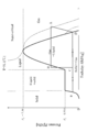
- FIG. 4 is a Mollier diagram when CO 2 is used as the refrigerant in the heat pump system 16.
- the gaseous phase CO 2 taken into the compressor 13 through the refrigerant circulation line 15 is compressed in the compressor 13 (D ⁇ A in FIG. 4) to form a high pressure gaseous phase CO 2 , and the refrigerant circulation line 15 Is supplied to the condenser.
- the gas phase CO 2 is cooled in a high pressure state to form liquid phase CO 2 (A ⁇ B in FIG. 4), and is supplied to the expansion valve 6 through the refrigerant inflow pipe 5.
- the high-pressure liquid phase CO 2 is expanded and reduced by the expansion valve to form solid-gas two-phase CO 2 (B ⁇ C in FIG. 4), and the solid-gas two-phase CO 2 is an evaporator (cyclone type refrigerator)
- the refrigerant flows into the internal space 1b of the cylindrical portion 1 of the evaporator (cyclone type refrigeration system) from the refrigerant inlet 1c.
- the inflowing solid-gas two-phase CO 2 forms a vortex that descends the internal space 1b and separates into solid-phase CO 2 and gas-phase CO 2 (C ⁇ E in FIG. 4 (solid-gas two-phase CO 2 solid CO corresponding to the second separation step) and 4 C ⁇ D (corresponding to the vapor phase CO 2 separation process from the solid-gas two-phase CO 2)).
- the solid phase CO 2 is deposited in the cavity 4 a of the cooling unit 4 of the evaporator (cyclone-type refrigerator), while the gas phase CO 2 forms a rising vortex through the inner space of the falling vortex, and the exhaust is exhausted. From the pipe 3, it is taken into the compressor 13 through the refrigerant circulation line 15.
- the solid phase CO 2 deposited in the cavity 4a of the evaporator (cyclone type refrigerator) is sublimated by the heat of the fluid to be cooled (E ⁇ D in FIG. 4), and the cold heat by this sublimation is supplied to the fluid to be cooled .
- FIG. 6 is a Mollier diagram when using a known evaporator instead of the cyclonic refrigeration system of the present invention in the heat pump system 16 of FIG. 3 and using CO 2 as a refrigerant, where D ⁇ A is a compressor 13, A ⁇ B corresponds to the condensation process in the condenser 14, B ⁇ C corresponds to the expansion process in the expansion valve (pressure reducer) 6, C ⁇ D corresponds to the evaporation process in the evaporator It corresponds.
- the enthalpy obtained in the evaporation process in the evaporator is significantly higher than that of the conventional example. It is increasing. This is because, in the conventional example, solid-gas two-phase CO 2 is subjected to heat exchange with the fluid to be cooled, and the latent heat of solid-phase CO 2 in the solid-gas two-phase state is used to cool the fluid to be cooled.
- FIG. 5 is a Mollier diagram in the case where the cyclone type refrigerating apparatus of FIG. 2 is provided instead of the cyclone type refrigerating apparatus of FIG. 1 as an evaporator in the heat pump system 16 of FIG. 13,
- a ⁇ B corresponds to the condensation process in the condenser 14
- B ⁇ C corresponds to the expansion process in the expansion valve (depressurizer) 6
- C ⁇ E is the evaporator (cyclone type refrigeration) C) corresponds to the separation process of the gas-phase refrigerant from the solid-gas two-phase refrigerant in the evaporator (cyclone type refrigeration apparatus).
- E ⁇ D correspond to the evaporation process of the solid phase refrigerant S in the evaporator (cyclone type refrigeration system).
- the compressor is used alone in the CO 2 compression process (D ⁇ A), but the compressor is formed by connecting a low-pressure stage compressor and a high-pressure stage compressor in series.
- An intercooler may be provided between the stage compressor and the high pressure stage compressor to perform two-stage compression of gas phase CO 2 .
- gas phase CO 2 can be easily compressed to a saturation pressure or a supercritical pressure.
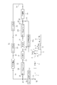
- FIG. 7 is a view showing a schematic configuration of a cyclone type cold heat recovery unit provided with the cyclone type refrigeration system of FIG.
- the same components as those shown in FIG. 1 are designated by the same reference numerals, and the detailed description thereof will be omitted below.
- a cyclone type cold heat recovery unit 17 includes the cyclone type refrigerating apparatus shown in FIG. 1, the outlet of the exhaust pipe 3 of the cyclone type refrigerating apparatus, and the other end 5b of the refrigerant inflow pipe 5.
- a refrigerant circulation line 18 to be connected is provided.
- a compressor 19 for compressing the gas phase refrigerant discharged from the exhaust pipe 3 of the cyclone type refrigeration system is disposed in the refrigerant circulation pipeline 18, and the compressor 18 in the refrigerant circulation pipeline 18 downstream of the compressor 19
- First and second condensers 20, 21 for condensing the compressed gas phase refrigerant to form a liquid phase refrigerant are arranged in series.
- a heat exchanger 22 is disposed downstream of the first and second condensers 20 and 21 in the refrigerant circulation pipeline 18.
- downstream side of the heat exchanger 22 and the upstream side of the compressor 18 in the refrigerant circulation line 18 are connected by a bypass line 23.
- An expansion valve (pressure reducing device) 24 is disposed in the bypass line 23, and an evaporator 25 is disposed downstream of the expansion valve 24 in the bypass line 23.
- a first flow rate controller 27 is disposed downstream of a connection point 26 between the refrigerant circulation pipeline 18 and the upstream end of the bypass pipeline 23, and a second flow controller 27 is disposed upstream of the expansion valve 24 in the bypass pipeline 23.
- a flow controller 28 is arranged.
- the third flow rate controller 30a is disposed on the upstream side of the connection point 29 of the refrigerant circulation pipeline 18 with the downstream end of the bypass pipeline 23, and the fourth flow controller 30a is disposed downstream of the evaporator 25 in the bypass pipeline 23.
- the flow controller 30b of the second embodiment is disposed.
- the third and fourth flow controllers 30a, 30b have a main purpose of pressure control. That is, in this embodiment, when CO 2 is used as the refrigerant, the cyclone type refrigeration system operates under the pressure condition below the triple point where CO 2 is in the solid-gas two phase state, while the evaporator 25 is CO 2
- the third and fourth flow controllers 30a and 30b operate so as to maintain the pressure conditions described above.
- the fluid to be cooled which exchanges heat with the solid phase refrigerant S in the heat exchanger 8 of the cyclone type refrigeration system preferably comprises a cold cooling medium (carbon dioxide, ethanol, helium, etc.) .
- a cold cooling medium carbon dioxide, ethanol, helium, etc.
- a part of the liquid phase refrigerant flowing through the refrigerant circulation pipeline 18 is diverted to the bypass pipeline 23 to operate the cyclone type refrigerating apparatus and the evaporator 25 simultaneously, or to the bypass pipeline 23.
- the supply of the liquid-phase refrigerant can be stopped to operate only the cyclone-type refrigeration system, or the supply of the liquid-phase refrigerant to the cyclone-type refrigeration system can be stopped to operate only the evaporator 25.
- the temperature range of recoverable cold energy is expanded as compared with the embodiment shown in FIG.
- FIG. 8 is a view showing a schematic configuration of a cascade heat pump system in which the cyclone type cold heat recovery unit of FIG. 7 is incorporated as a low side cycle.
- the same components as those shown in FIG. 7 will be assigned the same reference numerals, and the detailed description thereof will be omitted below.
- the cascade heat pump system 31 includes a low side cycle 32 and a high side cycle 33, and the low side cycle 32 is composed of the cyclone type cold heat recovery unit 17 shown in FIG. ing.
- the heat exchanger 22 of the cyclone type cold heat recovery unit 17 forms the low side heat exchanger 35 of the cascade heat exchanger 34 of the cascade heat pump system 31.
- the high-temperature side cycle 33 is between the high-temperature side heat exchanger 36 forming a cascade heat exchanger 34 in pair with the low-temperature side heat exchanger 35, and the outlet 36 a and the inlet 36 b of the high-temperature side heat exchanger 36.
- a compressor 38 disposed downstream of the high-temperature-side heat exchanger 36 in the high-temperature-side refrigerant circulation pipeline 37 extending in the vertical direction, and a compressor in the high-temperature-region refrigerant circulation pipeline 37
- the third and fourth condensers 39, 40 disposed in series downstream of 38 and the third and fourth condensers 39, 40 in the upstream refrigerant circulation line 37 are disposed downstream of the third and fourth condensers 39, 40.
- An expansion valve (depressurizer) 41 is provided.
- Reference Signs List 1 cylindrical portion 1a upper end opening 1b internal space 1c refrigerant inlet 2 inner flange 3 exhaust pipe 4 cooling portion 4a cavity 5 refrigerant inlet pipe 5a one end 5b other end 6 expansion valve (depressurizer) 7 to-be-cooled fluid circulation pipeline 7a to-be-cooled fluid discharge pipeline 7b to-be-cooled fluid supply pipeline 8 heat exchanger 8a fluid outlet 8b fluid inlet 9 cooling load 10 pump 11 vortex control body 11a lower part 11b middle part 11c upper part 11d upper end surface 11e Bottom 12 Through-hole 13 Compressor 14 Condenser 15 Refrigerant circulation pipeline 16 Heat pump system 17 Cyclone type cold heat recovery unit 18 Refrigerant circulation pipeline 19 Compressor 20 1st condenser 21 2nd condenser 22 Heat exchanger 23 Bypass line 24 expansion valve (pressure reducer) 25 evaporator 26 connection point 27 first flow rate controller 28 second flow rate controller 29 connection point 30a third flow rate controller 30b fourth flow rate controller 31 cascade heat pump system 32 low
Landscapes
- Engineering & Computer Science (AREA)
- Physics & Mathematics (AREA)
- Mechanical Engineering (AREA)
- Thermal Sciences (AREA)
- General Engineering & Computer Science (AREA)
- Chemical & Material Sciences (AREA)
- Chemical Kinetics & Catalysis (AREA)
- Combustion & Propulsion (AREA)
- Cyclones (AREA)
Abstract
La présente invention est pourvue d'une partie cylindre (1), d'un tuyau d'échappement (3), d'une partie de refroidissement (4) ayant une cavité (4a) qui passe à travers un espace interne (1b) de la partie cylindre, d'un tuyau d'entrée de fluide frigorigène (5), et d'un dispositif de décompression (6). Un fluide frigorigène en phase liquide qui a été condensé sous haute pression est fourni à un tuyau d'alimentation en fluide frigorigène et est décomprimé par le dispositif de décompression pour former un fluide frigorigène biphasé solide-gaz. Le fluide frigorigène biphasé solide-gaz s'écoule dans l'espace interne de la partie de cylindre et forme une spirale vers le bas, et est séparé en un fluide frigorigène en phase solide S et en un fluide frigorigène en phase gazeuse. Le fluide frigorigène en phase solide S s'accumule dans la cavité, et le fluide frigorigène en phase gazeuse forme une spirale vers le haut en passant d'une partie inférieure de la cavité à travers l'espace interne à l'intérieur de la spirale vers le bas et s'écoule hors du tuyau d'échappement. La présente invention comprend également : des conduites (7a, 7b) à travers lesquelles circule un fluide à refroidir, lesdites conduites (7a, 7b) à travers lesquelles circule un fluide à refroidir s'étendent à travers la cavité de la partie de refroidissement, et un fluide à refroidir à partir d'une charge de refroidissement (9) est mis en circulation via les conduites à travers lesquelles circule un fluide à refroidir; un échangeur de chaleur (8) disposé sur une partie des conduites à travers laquelle circule un fluide à refroidir qui se trouve à l'intérieur de la cavité, l'échangeur de chaleur (8) effectuant un échange de chaleur entre le fluide frigorigène en phase solide S et le fluide à refroidir; et une pompe (10) qui fait circuler le fluide à refroidir.
Priority Applications (1)
| Application Number | Priority Date | Filing Date | Title |
|---|---|---|---|
| EP19741070.7A EP3742070B1 (fr) | 2018-01-19 | 2019-01-18 | Unité de récupération de chaleur cyclone et système de pompe à chaleur équipé de la dite unité de récupération de chaleur cyclone |
Applications Claiming Priority (2)
| Application Number | Priority Date | Filing Date | Title |
|---|---|---|---|
| JP2018007071A JP6945202B2 (ja) | 2018-01-19 | 2018-01-19 | サイクロン式冷凍装置および該サイクロン式冷凍装置を備えたヒートポンプシステム |
| JP2018-007071 | 2018-01-19 |
Publications (1)
| Publication Number | Publication Date |
|---|---|
| WO2019142919A1 true WO2019142919A1 (fr) | 2019-07-25 |
Family
ID=67301511
Family Applications (1)
| Application Number | Title | Priority Date | Filing Date |
|---|---|---|---|
| PCT/JP2019/001499 WO2019142919A1 (fr) | 2018-01-19 | 2019-01-18 | Dispositif de réfrigération cyclone, unité de récupération de froid/ chaleur cyclone, et système de pompe à chaleur équipé dudit dispositif de réfrigération cyclone ou unité de récupération de froid/chaleur cyclone |
Country Status (3)
| Country | Link |
|---|---|
| EP (1) | EP3742070B1 (fr) |
| JP (1) | JP6945202B2 (fr) |
| WO (1) | WO2019142919A1 (fr) |
Families Citing this family (2)
| Publication number | Priority date | Publication date | Assignee | Title |
|---|---|---|---|---|
| US12050053B2 (en) * | 2020-03-12 | 2024-07-30 | Raytheon Company | Consumable dry ice cooling |
| DE102020133808A1 (de) | 2020-12-16 | 2022-06-23 | Technische Universität Dresden, Körperschaft des öffentlichen Rechts | Vorrichtung, System und Verfahren zum Kühlen eines Mediums |
Citations (3)
| Publication number | Priority date | Publication date | Assignee | Title |
|---|---|---|---|---|
| JPS5098359U (fr) * | 1973-12-03 | 1975-08-15 | ||
| JPH1130599A (ja) * | 1997-07-09 | 1999-02-02 | Toyo Eng Works Ltd | ドライアイスの蓄熱を利用する二元冷却設備の蓄熱量 計測方法及び同二元冷却設備 |
| JP2004308972A (ja) | 2003-04-03 | 2004-11-04 | Mayekawa Mfg Co Ltd | Co2冷凍機 |
Family Cites Families (4)
| Publication number | Priority date | Publication date | Assignee | Title |
|---|---|---|---|---|
| US2043190A (en) * | 1931-09-10 | 1936-06-02 | Mccabe Maier Corp | Refrigerating apparatus and method |
| US4224801A (en) * | 1978-11-13 | 1980-09-30 | Lewis Tyree Jr | Stored cryogenic refrigeration |
| JP2007248005A (ja) * | 2006-03-17 | 2007-09-27 | Sanyo Electric Co Ltd | 冷蔵庫 |
| DE102012008592A1 (de) * | 2012-04-27 | 2013-10-31 | Messer France S.A.S | Verfahren und Vorrichtung zum Kühlen von Produkten |
-
2018
- 2018-01-19 JP JP2018007071A patent/JP6945202B2/ja active Active
-
2019
- 2019-01-18 WO PCT/JP2019/001499 patent/WO2019142919A1/fr unknown
- 2019-01-18 EP EP19741070.7A patent/EP3742070B1/fr active Active
Patent Citations (3)
| Publication number | Priority date | Publication date | Assignee | Title |
|---|---|---|---|---|
| JPS5098359U (fr) * | 1973-12-03 | 1975-08-15 | ||
| JPH1130599A (ja) * | 1997-07-09 | 1999-02-02 | Toyo Eng Works Ltd | ドライアイスの蓄熱を利用する二元冷却設備の蓄熱量 計測方法及び同二元冷却設備 |
| JP2004308972A (ja) | 2003-04-03 | 2004-11-04 | Mayekawa Mfg Co Ltd | Co2冷凍機 |
Non-Patent Citations (1)
| Title |
|---|
| See also references of EP3742070A4 |
Also Published As
| Publication number | Publication date |
|---|---|
| EP3742070A4 (fr) | 2021-10-20 |
| JP2019124432A (ja) | 2019-07-25 |
| EP3742070B1 (fr) | 2023-07-19 |
| EP3742070A1 (fr) | 2020-11-25 |
| JP6945202B2 (ja) | 2021-10-06 |
Similar Documents
| Publication | Publication Date | Title |
|---|---|---|
| US6622518B2 (en) | Cryogenic refrigerating system | |
| JP4973872B2 (ja) | Co2冷凍機 | |
| US7559212B2 (en) | Refrigerant pressurization system with a two-phase condensing ejector | |
| DK2676085T3 (en) | LIQUID / DAMPFASESEPARERINGSAPPARAT | |
| CN102232167B (zh) | 跨临界制冷循环中的液体蒸气分离 | |
| US6658888B2 (en) | Method for increasing efficiency of a vapor compression system by compressor cooling | |
| ITRM20070520A1 (it) | Impianto frigorifero a co2 con compressore a viti ad immersione in olio con disposizione a due stadi | |
| CN113124581B (zh) | 涡轮制冷机 | |
| JP2008224206A (ja) | 2元冷凍サイクル装置 | |
| JP2016056966A (ja) | ターボ冷凍機 | |
| JP2006292229A (ja) | Co2冷凍サイクル装置及びその超臨界冷凍運転方法 | |
| WO2019142919A1 (fr) | Dispositif de réfrigération cyclone, unité de récupération de froid/ chaleur cyclone, et système de pompe à chaleur équipé dudit dispositif de réfrigération cyclone ou unité de récupération de froid/chaleur cyclone | |
| JP4694365B2 (ja) | オイルセパレータ付き減圧器モジュール | |
| JP2004308972A (ja) | Co2冷凍機 | |
| JP2009300021A (ja) | 冷凍サイクル装置 | |
| JP2008275211A (ja) | 蒸気圧縮式冷凍サイクル | |
| KR101092692B1 (ko) | 이코노마이저 및 이를 구비하는 다단 압축식 냉동기 | |
| JP6176470B2 (ja) | 冷凍機 | |
| WO2005066554A1 (fr) | Refrigerateur a temperature ultra-basse, systeme de refrigeration et appareil a vide | |
| JP2008185256A (ja) | 冷凍装置 | |
| JP2005098635A (ja) | 冷凍サイクル | |
| CN110195949B (zh) | 制冷系统及方法 | |
| JP4161871B2 (ja) | 冷凍サイクル装置 | |
| JP2009186074A (ja) | 冷凍装置 | |
| JP2003028518A (ja) | 空気調和機 |
Legal Events
| Date | Code | Title | Description |
|---|---|---|---|
| 121 | Ep: the epo has been informed by wipo that ep was designated in this application |
Ref document number: 19741070 Country of ref document: EP Kind code of ref document: A1 |
|
| NENP | Non-entry into the national phase |
Ref country code: DE |
|
| ENP | Entry into the national phase |
Ref document number: 2019741070 Country of ref document: EP Effective date: 20200819 |