WO2019142614A1 - 容器及びその使用 - Google Patents
容器及びその使用 Download PDFInfo
- Publication number
- WO2019142614A1 WO2019142614A1 PCT/JP2018/047546 JP2018047546W WO2019142614A1 WO 2019142614 A1 WO2019142614 A1 WO 2019142614A1 JP 2018047546 W JP2018047546 W JP 2018047546W WO 2019142614 A1 WO2019142614 A1 WO 2019142614A1
- Authority
- WO
- WIPO (PCT)
- Prior art keywords
- integer
- carbon atoms
- hydrogel
- group
- linear
- Prior art date
- Legal status (The legal status is an assumption and is not a legal conclusion. Google has not performed a legal analysis and makes no representation as to the accuracy of the status listed.)
- Ceased
Links
Images


Classifications
-
- C—CHEMISTRY; METALLURGY
- C07—ORGANIC CHEMISTRY
- C07C—ACYCLIC OR CARBOCYCLIC COMPOUNDS
- C07C247/00—Compounds containing azido groups
- C07C247/02—Compounds containing azido groups with azido groups bound to acyclic carbon atoms of a carbon skeleton
-
- C—CHEMISTRY; METALLURGY
- C08—ORGANIC MACROMOLECULAR COMPOUNDS; THEIR PREPARATION OR CHEMICAL WORKING-UP; COMPOSITIONS BASED THEREON
- C08G—MACROMOLECULAR COMPOUNDS OBTAINED OTHERWISE THAN BY REACTIONS ONLY INVOLVING UNSATURATED CARBON-TO-CARBON BONDS
- C08G65/00—Macromolecular compounds obtained by reactions forming an ether link in the main chain of the macromolecule
- C08G65/02—Macromolecular compounds obtained by reactions forming an ether link in the main chain of the macromolecule from cyclic ethers by opening of the heterocyclic ring
- C08G65/32—Polymers modified by chemical after-treatment
-
- C—CHEMISTRY; METALLURGY
- C12—BIOCHEMISTRY; BEER; SPIRITS; WINE; VINEGAR; MICROBIOLOGY; ENZYMOLOGY; MUTATION OR GENETIC ENGINEERING
- C12M—APPARATUS FOR ENZYMOLOGY OR MICROBIOLOGY; APPARATUS FOR CULTURING MICROORGANISMS FOR PRODUCING BIOMASS, FOR GROWING CELLS OR FOR OBTAINING FERMENTATION OR METABOLIC PRODUCTS, i.e. BIOREACTORS OR FERMENTERS
- C12M1/00—Apparatus for enzymology or microbiology
-
- C—CHEMISTRY; METALLURGY
- C12—BIOCHEMISTRY; BEER; SPIRITS; WINE; VINEGAR; MICROBIOLOGY; ENZYMOLOGY; MUTATION OR GENETIC ENGINEERING
- C12N—MICROORGANISMS OR ENZYMES; COMPOSITIONS THEREOF; PROPAGATING, PRESERVING, OR MAINTAINING MICROORGANISMS; MUTATION OR GENETIC ENGINEERING; CULTURE MEDIA
- C12N1/00—Microorganisms; Compositions thereof; Processes of propagating, maintaining or preserving microorganisms or compositions thereof; Processes of preparing or isolating a composition containing a microorganism; Culture media therefor
Definitions
- the present invention relates to a container and its use. More specifically, the present invention relates to a container, a kit, a method of producing a hydrogel having a concentration gradient of a target substance, a method of cell culture, and a method of producing a pituitary.
- a container a kit
- a method of producing a hydrogel having a concentration gradient of a target substance a method of cell culture
- a method of producing a pituitary a method of producing a pituitary.
- pluripotent stem cells such as embryonic stem cells (ES cells) and induced pluripotent stem cells (iPS cells)
- ES cells embryonic stem cells
- iPS cells induced pluripotent stem cells
- Patent Document 1 includes suspension culture (3D suspension culture) of aggregates of human pluripotent stem cells in a medium containing an osteogenic factor signal transduction pathway activator and an Shh signal pathway agonist. A method of producing human cell aggregates comprising the glandular pituitary or its precursor tissue is described.
- FIG. 1 is a schematic view showing the development of a mouse after formation of a pituitary primordia, which should also be referred to as the latter half of pituitary differentiation.
- BMP, FGF, Shh and Wnt represent differentiation induction signals.
- the signal from the dorsal hypothalamus and the signal from the ventral oral epidermis form a concentration gradient on the pituitary primordia.
- neural crest-derived mesenchymal cells migrate around the lateral direction, and the signal is also secreted from there.
- Patent document 2 describes what developed the manufacturing method of patent document 1 further. Specifically, 3D culture of mouse or human ES cells or iPS cells can simultaneously induce differentiation of hypothalamus and oral ectoderm essential for pituitary differentiation into one 3D cell mass. it can. Subsequently, the pituitary primordia is induced spontaneously and eventually differentiates into pituitary hormone producing cells.
- conventional 3D culture methods also have limitations.
- pituitary of a living body a plurality of types of pituitary hormone-producing cells are present at unevenly distributed sites for each type in rostral and caudal, ventral and dorsal sides.
- pituitary hormone-producing cells can be induced for each type, but multiple types of pituitary hormone-producing cells can not be polarized and induced simultaneously.
- an object of this invention is to provide the technique which forms the concentration gradient of an object substance.
- the present invention includes the following aspects.
- a container main body in which an internal space capable of storing liquid is formed, and a partition dividing the internal space into a plurality of liquid reservoirs, and at least two of the plurality of liquid reservoirs in the partition A container communicating with one another, wherein a hole is formed in which a hydrogel is held.
- a compound for fixing the hydrogel is laminated on at least a part of the surface of the hole.
- a 1 independently represents a single bond or a linear or branched alkylene group having 1 to 20 carbon atoms
- R 1 to R 4 each independently represent a hydrogen atom -L-Z 1 , -O (CH 2 CH 2 O) n -L-Z 1 or a linear or branched alkyl group having 1 to 20 carbon atoms.
- L each independently represents a single bond or a divalent group having 1 to 20 carbon atoms
- Z 1 represents an alkynyl group
- n represents an integer of 20 to 500.
- p represents an integer of 0 or more.
- a plurality of R 2 and R 4 may be identical to or different from each other.
- a 1 independently represents a single bond or a linear or branched alkylene group having 1 to 20 carbon atoms
- R 5 to R 8 each independently represent a hydrogen atom And -L-Z 2 , -O (CH 2 CH 2 O) n -L-Z 2 or a linear or branched alkyl group having 1 to 20 carbon atoms.
- L each independently represents a single bond or a divalent group having 1 to 20 carbon atoms
- Z 2 represents an azide group
- n represents an integer of 20 to 500.
- p represents an integer of 0 or more.
- a plurality of R 6 and R 8 may be identical to or different from each other.
- a 1 independently represents a single bond or a linear or branched alkylene group having 1 to 20 carbon atoms
- R 1 to R 4 each independently represent a hydrogen atom -L-Z 1 , -O (CH 2 CH 2 O) n -L-Z 1 or a linear or branched alkyl group having 1 to 20 carbon atoms.
- L each independently represents a single bond or a divalent group having 1 to 20 carbon atoms
- Z 1 represents an alkynyl group
- n represents an integer of 20 to 500.
- p represents an integer of 0 or more. When p is an integer of 2 or more, a plurality of R 2 and R 4 may be identical to or different from each other.
- a 1 independently represents a single bond or a linear or branched alkylene group having 1 to 20 carbon atoms
- R 5 to R 8 each independently represent a hydrogen atom And -L-Z 2 , -O (CH 2 CH 2 O) n -L-Z 2 or a linear or branched alkyl group having 1 to 20 carbon atoms.
- L each independently represents a single bond or a divalent group having 1 to 20 carbon atoms
- Z 2 represents an azide group
- n represents an integer of 20 to 500.
- p represents an integer of 0 or more. When p is an integer of 2 or more, a plurality of R 6 and R 8 may be identical to or different from each other.
- a kit comprising the container according to any one of [1] to [3] and the material of the hydrogel.
- the material of the hydrogel contains a compound represented by the following formula (A) and a compound represented by the following formula (B).
- a 1 independently represents a single bond or a linear or branched alkylene group having 1 to 20 carbon atoms
- R 1 to R 4 each independently represent a hydrogen atom -L-Z 1 , -O (CH 2 CH 2 O) n -L-Z 1 or a linear or branched alkyl group having 1 to 20 carbon atoms.
- L each independently represents a single bond or a divalent group having 1 to 20 carbon atoms
- Z 1 represents an alkynyl group
- n represents an integer of 20 to 500.
- p represents an integer of 0 or more.
- a plurality of R 2 and R 4 may be identical to or different from each other.
- a 1 independently represents a single bond or a linear or branched alkylene group having 1 to 20 carbon atoms
- R 5 to R 8 each independently represent a hydrogen atom And -L-Z 2 , -O (CH 2 CH 2 O) n -L-Z 2 or a linear or branched alkyl group having 1 to 20 carbon atoms.
- L each independently represents a single bond or a divalent group having 1 to 20 carbon atoms
- Z 2 represents an azide group
- n represents an integer of 20 to 500.
- p represents an integer of 0 or more.
- a plurality of R 6 and R 8 may be identical to or different from each other.
- D a step of forming a concentration gradient of the target substance in the hydrogel as a result of each putting, thereby producing the hydrogel having a concentration gradient of the target substance.
- a 1 independently represents a single bond or a linear or branched alkylene group having 1 to 20 carbon atoms
- R 1 to R 4 each independently represent a hydrogen atom -L-Z 1 , -O (CH 2 CH 2 O) n -L-Z 1 or a linear or branched alkyl group having 1 to 20 carbon atoms.
- L each independently represents a single bond or a divalent group having 1 to 20 carbon atoms
- Z 1 represents an alkynyl group
- n represents an integer of 20 to 500.
- p represents an integer of 0 or more.
- a plurality of R 2 and R 4 may be identical to or different from each other.
- a 1 independently represents a single bond or a linear or branched alkylene group having 1 to 20 carbon atoms
- R 5 to R 8 each independently represent a hydrogen atom And -L-Z 2 , -O (CH 2 CH 2 O) n -L-Z 2 or a linear or branched alkyl group having 1 to 20 carbon atoms.
- L each independently represents a single bond or a divalent group having 1 to 20 carbon atoms
- Z 2 represents an azide group
- n represents an integer of 20 to 500.
- p represents an integer of 0 or more.
- a plurality of R 6 and R 8 may be identical to or different from each other.
- a step of disposing a cell-containing hydrogel in the pores of the container according to any one of [1] to [3], and at least two of the plurality of liquid reservoirs have different concentrations of the target substance from each other A cell culture method comprising the steps of: introducing a culture medium, and as a result, forming a concentration gradient of the target substance in the cell-containing hydrogel; and incubating the cell-containing hydrogel.
- the cell-containing hydrogel according to [11] which is obtained by mixing a compound represented by the following formula (A), a compound represented by the following formula (B), a culture medium and cells. Cell culture method described.
- a 1 independently represents a single bond or a linear or branched alkylene group having 1 to 20 carbon atoms
- R 1 to R 4 each independently represent a hydrogen atom -L-Z 1 , -O (CH 2 CH 2 O) n -L-Z 1 or a linear or branched alkyl group having 1 to 20 carbon atoms.
- L each independently represents a single bond or a divalent group having 1 to 20 carbon atoms
- Z 1 represents an alkynyl group
- n represents an integer of 20 to 500.
- p represents an integer of 0 or more. When p is an integer of 2 or more, a plurality of R 2 and R 4 may be identical to or different from each other.
- a 1 independently represents a single bond or a linear or branched alkylene group having 1 to 20 carbon atoms
- R 5 to R 8 each independently represent a hydrogen atom And -L-Z 2 , -O (CH 2 CH 2 O) n -L-Z 2 or a linear or branched alkyl group having 1 to 20 carbon atoms.
- L each independently represents a single bond or a divalent group having 1 to 20 carbon atoms
- Z 2 represents an azide group
- n represents an integer of 20 to 500.
- p represents an integer of 0 or more. When p is an integer of 2 or more, a plurality of R 6 and R 8 may be identical to or different from each other.
- the cell is a cell mass having pituitary primordium-like properties
- the target substance is glucocorticoid, bone morphogenetic protein (BMP), fibroblast growth factor (FGF), and sonic hedgehog (Shh) [11] or [12], which is a differentiation inducer selected from the group consisting of [14]
- a method for producing a pituitary comprising: a cell mass-containing hydrogel containing a cell mass having a property of pituitary primordium in the hole of the container according to any one of [1] to [3].
- the cell mass-containing hydrogel may be prepared by mixing a compound represented by the following formula (A), a compound represented by the following formula (B), a medium, and a cell mass having a property of pituitary primordia The production method according to [14], which is obtained.
- a 1 independently represents a single bond or a linear or branched alkylene group having 1 to 20 carbon atoms
- R 1 to R 4 each independently represent a hydrogen atom -L-Z 1 , -O (CH 2 CH 2 O) n -L-Z 1 or a linear or branched alkyl group having 1 to 20 carbon atoms.
- L each independently represents a single bond or a divalent group having 1 to 20 carbon atoms
- Z 1 represents an alkynyl group
- n represents an integer of 20 to 500.
- p represents an integer of 0 or more. When p is an integer of 2 or more, a plurality of R 2 and R 4 may be identical to or different from each other.
- a 1 independently represents a single bond or a linear or branched alkylene group having 1 to 20 carbon atoms
- R 5 to R 8 each independently represent a hydrogen atom And -L-Z 2 , -O (CH 2 CH 2 O) n -L-Z 2 or a linear or branched alkyl group having 1 to 20 carbon atoms.
- L each independently represents a single bond or a divalent group having 1 to 20 carbon atoms
- Z 2 represents an azide group
- n represents an integer of 20 to 500.
- p represents an integer of 0 or more. When p is an integer of 2 or more, a plurality of R 6 and R 8 may be identical to or different from each other.
- FIG. 3 is a plan view of the container of Figure 2;
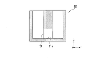
- FIG. 4 is a YZ sectional view taken along the line II shown in FIG. 3;
- FIG. 4 is a cross-sectional view taken along the line II-II shown in FIG. It is YZ sectional drawing of the culture apparatus using the container of FIG. It is XZ sectional drawing of the culture apparatus which used the container of FIG. It is a top view which shows an example of a container which has three liquid storage parts.
- FIG. 16 is a YZ sectional view taken along the line III-III shown in FIG.
- FIG. 16 is a cross-sectional view taken along line IV-IV shown in FIG. (A) is a photograph which shows a mode that the pregel solution was introduce
- FIG. (B) is a photograph which shows a mode that the pregel solution was introduce
- (A) And (b) is a photograph which shows the state which introduced the liquid into the 1st liquid storage part and the 2nd liquid storage part of the container which introduced the hydrogel to the hole, respectively.
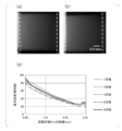
- (A) And (b) is a photograph of hydrogel at the time of using fluorescein as an object substance in Experimental example 4.
- (C) is a graph which shows the result at the time of using a fluorescein as an object substance in Experimental example 4.
- (A) And (b) is a photograph of hydrogel at the time of using FITC dextran as an object substance in Experimental example 4.
- (C) is a graph which shows the result at the time of using FITC dextran as an object substance in example 4 of an experiment.
- (A) And (b) is a photograph of hydrogel at the time of using YFP-CFP fusion protein as an object substance in Experimental example 4.
- (C) is a graph which shows the result at the time of using YFP-CFP fusion protein as an object substance in Experimental example 4.
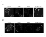
- (A) And (b) is a fluorescence-microscope photograph which shows the result of the immunostaining in Experimental example 5.
- FIG. It is a fluorescence-microscope photograph which shows the result of the immunostaining in Experimental example 6.
- the present invention includes a container main body in which an internal space capable of storing liquid is formed, and a partition dividing the internal space into a plurality of liquid reservoirs, and the partition is provided with the plurality of liquids
- a container in which at least two of the reservoirs communicate with each other and in which a hole for holding a hydrogel is formed.
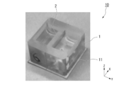
- Drawing 2 is a perspective view of container 10 which is an example of a container of this embodiment.
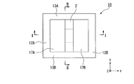
- FIG. 3 is a plan view of the container 10.
- FIG. 4 is a YZ sectional view taken along the line II shown in FIG.
- FIG. 5 is an XZ sectional view taken along the line II-II shown in FIG.
- the X direction is the length direction of the bottom plate 11 of the container body 1.
- the Y direction is a direction orthogonal to the X direction in the plane along the bottom plate 11.
- the Z direction is a direction orthogonal to the X direction and the Y direction, and is a thickness direction of the bottom plate 11.
- the Z direction is also referred to as the vertical direction or the height direction.
- the pair of side plates 12A and 12B and the pair of end plates 13A and 13B extend upward with respect to the bottom plate 11. Planar view refers to viewing from the Z direction.
- the container 10 includes a container body 1 and a partition 2.
- the container body 1 includes a bottom plate 11, a pair of side plates 12A and 12B, and a pair of end plates 13A and 13B.
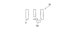
- the side plates 12A and 12B, the end plates 13A and 13B, and the partition 2 constitute a main portion 14 of the container 10.
- the main portion 14 may be integrally formed.
- the bottom plate 11 is rectangular in plan view.
- the side plates 12A and 12B are provided upright on the first major surface 11a of the bottom plate 11.
- the side plates 12A and 12B are formed along the XZ plane.
- the side plates 12A and 12B are, for example, rectangular when viewed from the thickness direction (Y direction).
- the two side plates 12A and 12B are formed apart in the Y direction.
- the end plates 13A and 13B are provided upright on the first major surface 11a of the bottom plate 11.
- the end plates 13A and 13B are formed along the YZ plane.
- the end plates 13A and 13B are rectangular when viewed in the thickness direction (X direction).
- the two end plates 13A and 13B are formed apart in the X direction.
- a space surrounded by the bottom plate 11, the side plates 12A and 12B, and the end plates 13A and 13B is referred to as an internal space 15.
- the lower edges of the side plates 12A and 12B and the lower edges of the end plates 13A and 13B and the bottom plate 11 are joined in a liquid tight manner. Therefore, the container 10 can store liquid in the internal space 15.
- the bottom plate 11 closes the lower openings of the liquid reservoirs 17A and 17B (described later).
- the partition 2 is provided upright on the first major surface 11 a of the bottom plate 11.
- the partition 2 is formed along the XZ plane.
- the partition 2 is rectangular when viewed from the thickness direction (Y direction).
- the partition 2 is parallel to the side plates 12A and 12B.
- the partition wall 2 is formed between the side plates 12A and 12B at a distance from the side plates 12A and 12B.
- the partition wall 2 has a constant thickness.
- the lower edge 2 d of the partition wall 2 is liquid-tightly joined to the first major surface 11 a of the bottom plate 11.
- the side edges 2fa and 2fb of the partition 2 reach the inner surfaces 13Aa and 13Ba of the end plates 13A and 13B, respectively.
- the upper edge 2e of the partition 2 is at the same height position as the upper edges 12Ab, 12Bb of the side plates 12A, 12B and the upper edges 13Ab, 13Bb of the end plates 13A, 13B.
- the partition 2 divides the internal space 15 into two liquid reservoirs 17A and 17B in the container body 1.
- the partition 2 separates the two liquid reservoirs 17A and 17B.
- the first liquid storage portion 17A is a space formed between the one surface 2a (the first main surface 2a) of the partition wall 2 and the first side plate 12A.
- the second liquid storage portion 17B is a space formed between the other surface 2b of the partition wall 2 (the second main surface 2b) and the second side plate 12B.
- a hole 21 is formed in the partition 2.
- the hole 21 is a through hole which penetrates the partition 2 in the thickness direction (Y direction).
- the holes 21 communicate the first liquid reservoir 17A with the second liquid reservoir 17B.
- the shape of the hole 21 viewed from the thickness direction (Y direction) of the partition 2 is rectangular.
- the lower edge 21 a and the upper edge 21 c of the hole 21 extend in the X direction.
- the side edges 21ba and 21bb of the holes 21 extend in the Z direction.
- the bottom surface 23a and the top surface 23c of the hole 21 are along the XY plane.
- the bottom surface 23a and the top surface 23c are parallel to each other.
- the pair of side surfaces 23 ba and 23 bb of the hole 21 are along the YZ plane.
- the side surfaces 23ba and 23bb are parallel to one another.
- the bottom surface 23 a coincides with the lower edge 21 a when viewed from the thickness direction (Y direction) of the partition 2.
- the side surfaces 23ba and 23bb respectively coincide with the side edges 21ba and 21bb when viewed from the Y direction.
- the top surface 23c coincides with the upper edge 21c when viewed from the Y direction.
- the holes 21 are formed at positions away from the peripheral edge (lower edge 2 d, upper edge 2 e, and side edges 2 fa, 2 fb) of the partition 2. That is, the lower edge 21 a of the hole 21 is located higher than the lower edge 2 d of the partition 2.
- the side edges 21 ba and 21 bb of the hole 21 are located closer to the inner side (in the direction in which the side edges 2 fa and 2 fb approach each other) than the side edges 2 fa and 2 fb of the partition 2.
- the upper edge 21 c of the hole 21 is at a lower position than the upper edge 2 e of the partition 2.
- the holes 21 hold the hydrogel.
- the pores 21 are filled with the pregel solution which is a hydrogel material to fill the pores 21 and subsequently, the hydrogel is retained in the pores 21 by gelling the pregel solution to form a hydrogel. It can be done.
- the hydrogel will be described later.
- the pregel solution when a part of the hole 21 of the container 10 is in contact with the peripheral edge of the partition 2 as described later in the embodiment, when the pregel solution is injected into the hole 21, the pregel solution leaks from the hole 21.
- the gelation of the pregel solution having such a shape results in the formation of a gel having a spherical surface, in which case the concentration gradient of the target substance from the surrounding medium is disturbed.
- the pregel solution when the pregel solution is injected into the hole 21 by forming the hole 21 of the container 10 at a position away from the peripheral edge of the partition 2, the inventors keep the pregel solution inside the hole 21. I found that I could do it.
- the pregel solution is gelled in this state, a gel having a flat surface in contact with the medium can be obtained.
- a concentration gradient of the target substance from the surrounding medium can be formed linearly, for example, as shown in the examples.
- it is important that the surface of the gel in contact with the medium is flat, so it is important to form the holes 21 of the container 10 at positions away from the periphery of the partition wall 2.
- the hole 21 of the container 10 is formed at a position away from the peripheral edge of the partition 2, thereby filling the hole 21 with the hole 21 (shape for closing the hole 21, substantially the same shape as the hole 21) Can form a hydrogel.
- the hydrogel is formed in a state where the holes 21 of the container 10 are filled, the liquid contained in the liquid storage portion 17A does not flow out to the liquid storage portion 17B as it is.
- the hydrogel may contain cells as described later.
- the cells are not particularly limited, and may be cells of human origin, cells of non-human animals, cells of plant origin, or cells of insect origin. Good.
- the cells may be single cells dissociated into pieces one by one or may be cell masses.
- the number of cells constituting the cell mass is not particularly limited, and can be, for example, 2 to 10 8 .
- the container of the present embodiment can be suitably used, for example, for the culture of cells. That is, it can be said that the container of this embodiment is a culture container.
- a compound for fixing a hydrogel is preferably laminated on at least a part of the surface of the hole 21.
- laminating the compound on the surface of the hole 21 means that the compound is attached to the surface of the hole 21 by physical adsorption, covalent bonding or the like.
- the hydrogel for example, a hydrogel formed by reacting a compound having an azide group with a compound having an alkynyl group can be suitably used. Therefore, when such a hydrogel is used, a compound having an azide group or an alkynyl group can be used as a compound for fixing the hydrogel. More specifically, examples thereof include azide poly-L-lysine and the like described later in the Examples. Moreover, as an alkynyl group, the dibenzo cyclooctyl (DBCO) group etc. are mentioned, for example.
- DBCO dibenzo cyclooctyl
- the compound for fixing the hydrogel does not necessarily have to form a covalent bond with the constituents of the hydrogel.
- the compound for fixing the hydrogel for example, poly-L-lysine, agarose, gelatin, polyhydroxyethyl methacrylate and the like can be used in addition to those described above.
- the hydrogel By laminating a compound for fixing the hydrogel on the surface of the hole 21, the hydrogel can be fixed to the hole 21 and the hydrogel can be prevented from coming off the hole 21.
- an operation of laminating a compound for fixing a hydrogel on the surface of the hole 21 may be referred to as “surface coating treatment”.
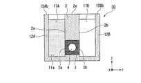
- FIG. 6 is a YZ sectional view showing the culture device 30 in which the holes 21 of the container 10 are filled with hydrogel.
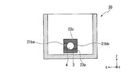
- FIG. 7 is an XZ sectional view of the culture device 30.
- the culture apparatus 30 includes the container body 1, the partition 2, and the hydrogel 3. That is, the culture apparatus 30 has a configuration in which the hydrogel 3 is provided in the hole 21 of the container 10.
- the hydrogel 3 is filled in the entire pores 21 with the cells 4 contained therein. As shown in FIG. 6, the hydrogel 3 is formed in the hole 21 over the entire thickness direction of the partition 2.
- the first main surface 3a of the hydrogel 3 faces the first liquid reservoir 17A.
- the first main surface 3 a of the hydrogel 3 is a surface along the XZ plane, and is flush with the first main surface 2 a of the partition 2.
- the second major surface 3b of the hydrogel 3 faces the second liquid reservoir 17B.
- the second major surface 3 b of the hydrogel 3 is a plane along the XZ plane, and is flush with the second major surface 2 b of the partition 2.
- the gel 3 is in contact with the bottom surface 23 a of the hole 21, the side surfaces 21 ba and 21 bb (see FIG. 6), and the top surface 23 c over the entire surface.
- the culture device 30 can be used to culture cells under the influence of a density gradient of a target substance.
- the container of the present embodiment is not limited to the container 10.
- the bottom plate 11 of the container 10 is rectangular in plan view, but the shape of the bottom plate 11 is not limited thereto.
- the shape of the bottom plate 11 may be, for example, a circle, an ellipse, or a polygon such as a triangle, a pentagon, or a hexagon.
- the outer surface of the container 10 is a substantially cube shape, it is not restricted to this.
- the outer surface of the container may be, for example, a rectangular parallelepiped shape, or may be, for example, a spherical shape, an ellipsoidal shape, or the like.
- FIG. 8 is a top view showing an example of a container having three liquid reservoirs.
- each partition wall may be the same, or may be different from each other as shown in FIG.
- the hole 21 is formed in the position where several partitions contact
- concentration gradients of a plurality of target substances can be formed in one hydrogel by introducing different target substances into the liquid reservoirs 17A1 and 17A2.
- the thickness of the partition 2 is constant, but the thickness of the partition 2 may not be constant.
- the number of the holes 21 of the container 10 shown in FIGS. 2 to 5 is one, the number of the holes 21 may be two or more as long as at least two liquid reservoirs are communicated. . Further, even when there are a plurality of holes 21, it is preferable that the plurality of holes 21 be formed at positions away from the periphery of the partition 2.
- the shape of the holes 21 viewed from the Y direction is not limited to a rectangle, and may be a circle, an ellipse, a triangle, a pentagon, a polygon such as a hexagon, or the like.
- the size of the opening to the first liquid storage portion 17A of the hole 21 and the size of the opening to the second liquid storage portion 17B may be the same or different.
- size of the cross-sectional area in XZ plane of the hole 21 is as follows.
- the cross-sectional area of the hole 21 in the XZ plane is constant in the thickness direction (Y direction) of the partition 2, the same area as the cross-sectional area of the hole 21 viewed from the thickness direction (Y direction) of the partition 2 Assuming a circle 22 (area equivalent circle), let the diameter (area equivalent diameter) of the circle 22 be “d”.
- the thickness of the partition wall 2 at the location where the hole 21 is formed is t.
- t: d is preferably 1: 0.5 to 1: 5, more preferably 1: 0.5 to 1: 2, and 1: 0.5 to 1: 1.5. More preferably, it is about 1: 1.
- t: d is preferably 1: 0.5 to 1: 5, more preferably 1: 0.5 to 1: 2, and 1: 0.5 to 1: 1.5. More preferably, it is about 1: 1.
- t: d is in the above range, for example, when a cell mass is disposed in a hydrogel, it becomes easy to increase the density gradient of the target substance in contact with the cell mass. In other words, it is easy to greatly change the concentration of the target substance in contact with the cell mass depending on the position of the cell mass.
- the volume per hole 21 is, for example, preferably 0.5 ⁇ L to 1 mL, more preferably 1 ⁇ L to 500 ⁇ L, and still more preferably 1 ⁇ L to 100 ⁇ L.
- the hydrogel can be easily injected into the hole 21.
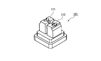
- the method of manufacturing the container 10 will be described with reference to FIGS.
- the container 10 can be molded using, for example, a mold 100 shown in FIG.
- the forming die 100 includes a first die 101, a second die 102, a hole forming piece 103, lower pieces 104 and 105, and a bottom plate 106.
- the first mold 101 has a first forming portion 111 shaped according to the first liquid reservoir 17A and a second forming portion 112 shaped according to the second liquid reservoir 17B. And. The first formation portion 111 and the second formation portion 112 are separated from each other.
- the hole forming piece 103 is bridged between the first forming portion 111 and the second forming portion 112.
- the formation piece 103 is attachable to and detachable from the first formation portion 111 and the second formation portion 112.
- the lower pieces 104 and 105 are provided at the tip of the first forming portion 111 and the second forming portion 112, respectively.
- the lower pieces 104 and 105 are attachable to and removable from the first forming portion 111 and the second forming portion 112, respectively.
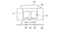
- the space between the first mold 101 and the second mold 102 is filled with the resin P and cured. Thereby, the main portion 14 (see FIGS. 2 to 5) is formed.
- the resin P filled between the first formation portion 111 and the second formation portion 112 becomes the partition wall 2 (see FIGS. 2 to 5).
- a hole 21 is formed in the partition 2 by the hole forming piece 103.
- the bottom plate 106 is removed from the second mold 102, and the lower pieces 104 and 105 are removed from the first forming portion 111 and the second forming portion 112.
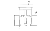
- the hole forming piece 103 can be easily removed from the forming portions 111 and 112.
- the first mold 101 is removed from the second mold 102.
- the formed main portion 14 is removed from the second mold 102, and the hole forming piece 103 is removed from the main portion 14.
- the bottom plate 11 (see FIGS. 2 to 5) prepared separately is joined to the lower part of the main part 14.
- the bonding between the main portion 14 and the bottom plate 11 may be performed using, for example, a silicone-based adhesive or the like, or may be performed by ultrasonic welding or the like.
- the container 10 shown in FIGS. 2 to 5 can be manufactured by the above method.
- Examples of the resin P forming the container 10 include silicone resins such as polydimethylsiloxane (PDMS), and thermoplastic resins such as polystyrene, polypropylene, polyethylene, and cycloolefin resins.
- silicone resins such as polydimethylsiloxane (PDMS)
- thermoplastic resins such as polystyrene, polypropylene, polyethylene, and cycloolefin resins.
- the present invention places a liquid having different concentrations of the target substance in at least two of the step of disposing the hydrogel in the hole of the container described above, and at least two of the plurality of liquid reservoirs.
- a process for producing the hydrogel having a concentration gradient of a target substance comprising: a step of forming a concentration gradient of the target substance on the hydrogel.
- FIG. 14 is a top view showing a container 10 having two liquid reservoirs.
- the hydrogel 3 is disposed in the hole 21 of the container 10.
- liquids having different concentrations of the target substance are respectively introduced into the first liquid storage section 17A and the second liquid storage section 17B.
- the target substance is dissolved only in the liquid introduced to the first liquid storage section 17A, and the liquid introduced to the second liquid storage section 17B does not include the target substance.
- the target substance diffuses from the side of the first liquid storage portion 17A of the hydrogel 3 and a concentration gradient of the target substance is formed on the hydrogel 3.
- hydrogel By hydrogel is meant a gel in which water is incorporated inside the polymer network.
- the hydrogel is not particularly limited.
- agarose gel low melting point agarose gel, alginic acid gel, carrageenan gel, chitosan gel, collagen gel, fibrin gel, fibrin gel, methyl cellulose gel, hydroxypropyl cellulose gel, Examples thereof include carboxymethyl cellulose gel, copolymer of polylactic acid and polyethylene glycol, synthetic gel of acrylic acid type, click cross-linked gel and the like.
- Examples of the click crosslinkable gel include hydrogels obtained by mixing a compound represented by the following formula (A), a compound represented by the following formula (B) and an aqueous liquid.
- a 1 independently represents a single bond or a linear or branched alkylene group having 1 to 20 carbon atoms
- R 1 to R 4 each independently represent a hydrogen atom -L-Z 1 , -O (CH 2 CH 2 O) n -L-Z 1 or a linear or branched alkyl group having 1 to 20 carbon atoms.
- L each independently represents a single bond or a divalent group having 1 to 20 carbon atoms
- Z 1 represents an alkynyl group
- n represents an integer of 20 to 500.
- p represents an integer of 0 or more. When p is an integer of 2 or more, a plurality of R 2 and R 4 may be identical to or different from each other.
- a 1 independently represents a single bond or a linear or branched alkylene group having 1 to 20 carbon atoms
- R 5 to R 8 each independently represent a hydrogen atom And -L-Z 2 , -O (CH 2 CH 2 O) n -L-Z 2 or a linear or branched alkyl group having 1 to 20 carbon atoms.
- L each independently represents a single bond or a divalent group having 1 to 20 carbon atoms
- Z 2 represents an azide group
- n represents an integer of 20 to 500.
- p represents an integer of 0 or more. When p is an integer of 2 or more, a plurality of R 6 and R 8 may be identical to or different from each other.
- the basic skeleton is water-soluble means that the compound represented by the above formula (A) containing the compound to be the basic skeleton or the basic skeleton is water or substantially neutral buffer at a temperature from normal temperature to 0 ° C. It means dissolving 10% by mass or more in the solution.
- a specific water solubility is a compound having the basic skeleton or the compound represented by the above formula (A) containing the basic skeleton in a buffer solution such as HEPES buffer at a concentration of about 1 to 100 mg / mL (pH 7.0 to It can be assessed by visual observation whether it is dispersed in 7.6) and dissolved.
- the azide group and the group which click-crosslinks with each other are groups which easily and specifically cause a crosslinking reaction with the azide group.
- Such groups include alkynyl groups. More specifically, groups having a cyclooctin ring or an azacyclooctic ring can be mentioned.
- a 1 when a plurality of A 1 is a linear or branched alkylene group having 1 to 20 carbon atoms, one or two or more non-adjacent two or more of —CH 2 — in the alkylene group are And each may be independently substituted by —CHCHCH—, —C ⁇ C—, —O—, —CO—, —COO—, —OCO—, or cyclohexylene group. Also, p may be 0 to 50.
- R 1 to R 4 are -L-Z 1 and two or more are -O (CH 2 CH 2 O) n -L-Z 1 Is preferred.
- the formed hydrogel is formed between the compound of formula (B).
- L may be an ester bond, an ether bond, an amide bond, a thioester bond, a carbamate bond, a carbonyl group, an alkylene group, a combination thereof, or the like.
- n is the average number of repetitions of ethylene glycol. n is 20 to 500, preferably 30 to 250, and more preferably 40 to 125.
- the average repetition number n of ethylene glycol can be estimated by measuring the molecular weight by gel filtration chromatography or mass spectrometry and estimating the number of R 1 to R 4 groups by NMR.
- Z 1 represents an alkynyl group, and specific examples thereof include a group having a cyclooctin ring or an azacyclooctin ring.
- the alkynyl group in the cyclooctin ring and the azacyclooctin ring is highly reactive to an azide group, and can be click-reacted with an azide group without using a catalyst such as a copper catalyst.
- the group having a cyclooctin ring or an azacyclooctin ring is preferably a group represented by any of the following formulas (1) to (4).
- the compound represented by the above formula (B) has a water-soluble basic skeleton, and has an azide group (-N 3 ).
- the water-soluble basic skeleton is the same as that described above for the compound represented by the formula (A).
- a 1 , L, n and p are the same as those described above for the formula (A).
- R 5 to R 8 are -L-Z 2 and two or more are -O (CH 2 CH 2 O) n -L-Z 2 Is preferred.
- the formed hydrogel is formed between the compound of formula (A).
- compounds represented by the following formulas (8) to (10) are suitably used as the compound represented by the above formula (B).
- L, n and p are the same as those described above for formula (A).
- p is preferably 1 to 3.
- Water-based liquid A hydrogel can be obtained by mixing the compound represented by the said Formula (A), the compound represented by the said Formula (B), and an aqueous liquid.
- the aqueous liquid refers to a liquid containing water as a main component.
- having water as the main component means that the proportion of water contained in the aqueous liquid is 50% by mass or more, preferably 60% by mass or more, and more preferably 70% by mass or more.
- aqueous liquid examples include water, a medium for cell culture, a pH buffer solution and the like.
- the cell culture medium may contain serum such as fetal calf serum, an antibiotic, a differentiation inducer, and the like.
- a hydrogel having a concentration gradient of the target substance can be produced.
- the hydrogel having a concentration gradient of the target substance means that the amount of the target substance contained in the hydrogel changes depending on the position on the hydrogel.
- the present invention places media having different concentrations of a target substance in at least two of the step of disposing the cell-containing hydrogel in the pores of the container described above and the plurality of liquid reservoirs,
- a cell culture method comprising the steps of: forming a concentration gradient of the target substance in the cell-containing hydrogel; and incubating the cell-containing hydrogel.
- cells can be cultured in a concentration gradient of a target substance.
- the cells may be similar to those described above.
- the cell culture method of the present embodiment can be suitably used, for example, for inducing differentiation of complex tissues and organs which need to be cultured in a concentration gradient of differentiation inducer.
- tissues and organs include the pituitary, brain, eye, liver, kidney, lung, digestive tract, pancreas and the like.
- pluripotent stem cells having HLA compatibility in a patient can be induced to differentiate, differentiation of a complex tissue or organ can be induced, and it can be used for regenerative medicine etc. .
- it can be used for screening of drug candidate compounds, safety testing of compounds, etc. using differentiated tissues and organs.
- hydrogel one similar to that described above can be used.
- a hydrogel obtained by mixing a compound represented by the above formula (A), a compound represented by the above formula (B) and an aqueous liquid can be suitably used.
- Cell-containing hydrogels can be prepared by including cells in the hydrogel.
- the hydrogel is a low melting point agarose
- the low melting point agarose is mixed with an aqueous liquid such as a medium, heated and dissolved, and then the low melting point agarose does not gel and the cells are not killed. Cool down. Subsequently, the cells are mixed and introduced into the pores 21 of the container 10 and gelated there. Thereby, the cell-containing hydrogel can be disposed in the hole 21 of the container 10.
- the hydrogel is a click cross-linked gel
- a compound represented by the above formula (B) and a medium are mixed to prepare a pregel solution, and a pregel solution is prepared.
- the cell-containing pregel solution can be prepared by mixing the cells with each other.
- the cell-containing pregel solution is introduced into the pores 21 of the container 10 and gelated there. Gelation can be carried out simply by leaving at room temperature. Thereby, the cell-containing hydrogel can be disposed in the hole 21 of the container 10.
- the click cross-linked gel can be gelled at room temperature and has low toxicity to cells, so the cell-containing hydrogel can be easily placed in the pores 21.
- the cell is a cell mass having the property of pituitary primordia
- the target substance is a differentiation inducer selected from the group consisting of glucocorticoid, BMP, FGF and Shh. It may be. In this way, it is possible to cause the concentration gradient of the differentiation inducer to act on the pituitary primordia, and to perform differentiation induction of the pituitary which has hitherto been impossible.
- LIM Homeobox 3 obtained by suspension culture (3D suspension culture) of a human clump of human pluripotent stem cells in a medium containing BMP and Shh LHX3) positive cell clusters are included.
- the present invention provides a method for producing a pituitary, comprising the step of disposing a cell mass-containing hydrogel containing a cell mass having a property of pituitary primordium in the hole of the container described above;
- the medium containing different concentrations of differentiation-inducing factors selected from the group consisting of glucocorticoid, BMP, FGF and Shh are respectively put in at least two of the plurality of liquid reservoirs, and as a result, the cell mass-containing hydro
- a manufacturing method comprising the steps of: forming a concentration gradient of the differentiation-inducing factor in a gel; and incubating the cell mass-containing hydrogel so that a pituitary body is formed from the cell mass.
- the cell mass-containing hydrogel includes a compound represented by the above formula (A), a compound represented by the above formula (B), a culture medium, and a cell mass having properties of pituitary primordia. It may be obtained by mixing.
- the invention provides a kit comprising the container described above and the hydrogel material described above.
- the kit of the present embodiment can be said to be, for example, a kit for producing a hydrogel having a concentration gradient of a target substance, a kit for cell culture, a kit for producing a pituitary, and the like.
- the material of the hydrogel may include the compound represented by the above formula (A) and the compound represented by the above formula (B).
- the compound represented by the above-mentioned formula (A) and the compound represented by the above-mentioned formula (B) may be separately stored in the container, or may be mixed and stored in the same container. It is also good.
- the click crosslinking reaction can proceed to form a hydrogel.
- DBCO dibenzocyclooctin
- A124 Click chemistry tools
- reaction solution described above was reacted with fluorescamine to measure the introduction rate of DBCO group to 4arm PEG.
- fluorescamine was first dissolved in DMSO to prepare a 3 mg / mL solution.
- 90 ⁇ L of a 100-fold diluted solution of the above DBCO-4 arm PEG solution and 30 ⁇ L of the fluorescamine solution were mixed, and allowed to react at room temperature in the dark for 30 minutes.
- DBCO-4 arm PEG was dialyzed.
- the dialysis was performed using a dialysis membrane with a molecular weight cut off of 6,000 to 8,000 and water (Milli Q water) as an external solution.
- the external fluid was replaced after 1 hour, 17 hours, 21 hours, 25 hours and 3 days from the start of dialysis.
- the dialyzed DBCO-4 arm PEG was lyophilized and stored at -20 ° C. until use.
- the introduction rate of DBCO group to 4 arm PEG was 93.4%, and the yield of DBCO-4 arm PEG was 776.3 mg.
- the molecular weight of the synthesized DBCO-4 armPEG was 43,168.
- Azide-4 arm PEG ⁇ Synthesis of Azide-4 arm PEG >> The above procedure was repeated except that Azide-PEG4-NHS solution in which 38 mg of Azide-PEG4-NHS (type “AZ103”, Click chemistry tools) was dissolved in 10 mL of DMSO was used instead of the above DBCO-sulfo-NHS solution. Azide-4arm PEG was synthesized, dialyzed, lyophilized, and stored at -20 ° C. until use.
- the rate of introduction of the Azide group to 4 arm PEG was 99.4%, and the yield of Azide-4 arm PEG was 1.0743 g.
- the molecular weight of the synthesized Azide-4 arm PEG was 42, 006.
- a 1 mM solution of DBCO-4 arm PEG is diluted with the above solvent, and 0.1, 0.2, 0.3, 0.4, 0.5, 0.6, 0.7, 0.8, 0. .9 mM solutions were prepared respectively.
- a DBCO-4 arm PEG solution and an Azide-4 arm PEG solution were each prepared at 0.5 mM, and 0.25 mM pregel solution was prepared by mixing equal volumes to form a hydrogel.
- FIG. 15 is a plan view of the container 10 '.
- FIG. 16 is a YZ sectional view taken along the line III-III shown in FIG.
- FIG. 17 is an XZ sectional view taken along the line IV-IV shown in FIG.
- the container 10 ′ is mainly different from the container 10 shown in FIGS. 2 to 5 in that a part of the hole 21 is in contact with the peripheral edge of the partition 2. As shown in FIGS. 16 and 17, the lower edge 21 a of the hole 21 of the container 10 ′ coincides with the lower edge 2 d of the partition 2.
- the DBCO-4 arm PEG solution and Azide-4 arm PEG solution were each prepared at 0.5 mM.
- gfCDM medium containing 5% KSR Invitrogen
- a 0.25 mM pre-gel solution was prepared by mixing equal volumes of DBCO-4 arm PEG solution and Azide 4 arm PEG solution.
- 30 ⁇ L of the pregel solution was injected into the hole 21 of the container 10 ′.
- FIG. 18A is a photograph showing the pregel solution introduced into the holes 21 of the container 10. As shown in FIG. 18 (a), when the container 10 was used, it became clear that the pregel solution was held without leaking from the holes 21.
- FIG. 18 (b) is a photograph showing the pregel solution introduced into the hole 21 of the container 10 '. As shown in FIG. 18 (b), it has become clear that the pregel solution leaks from the holes 21 when the container 10 ′ is used.
- Example 4 (Formation of concentration gradient of target substance) The same container 10 as shown in FIGS. 2 to 5 was used to prepare a hydrogel having a concentration gradient of the target substance.
- the hole 21 of the container 10 had a cubic shape of length ⁇ width ⁇ height 3 mm ⁇ 3 mm ⁇ 3 mm.
- Target substance As target substances, a fusion protein of fluorescein (molecular weight 332.31), FITC dextran (molecular weight 10,000), yellow fluorescent protein (YFP) and cyan fluorescent protein (CFP) (molecular weight 56,000 Da, hereinafter referred to as "YFP-CFP” .)It was used.
- YFP-CFP introduces a gene encoding a fusion protein in which ECFP is fused to the C-terminal side of EYFP via a linker peptide (GGNSSVDGG: SEQ ID NO: 1) into the expression vector pET21 (b) and expressed in E. coli Let it be prepared.
- the expressed YFP-CFP was purified using a nickel column using a histidine tag attached to the C-terminal side of YFP-CFP.
- the DBCO-4 arm PEG solution and Azide-4 arm PEG solution were each prepared at 0.5 mM. Water was used as the solvent. Subsequently, a 0.25 mM pre-gel solution was prepared by mixing equal volumes of DBCO-4 arm PEG solution and Azide 4 arm PEG solution. Subsequently, 30 ⁇ L of the pregel solution was injected into the hole 21 of the container 10. The pregel solution could be retained inside the holes 21 without leaking out of the holes 21. Subsequently, it was allowed to stand at room temperature for 30 minutes to form a hydrogel. As a result, the holes 21 were blocked by the hydrogel.
- a plurality of containers 10 in which hydrogels are formed in the holes 21 are prepared, and fluorescein (final concentration 10 ⁇ M), FITC dextran (final concentration 10 ⁇ M) or YFP-CFP (final concentration 600 ⁇ g / final) in the first liquid reservoir 17A of each container 10 1.5 mL of each aqueous solution of mL) was introduced. In addition, 1.5 mL of water was introduced into the second liquid reservoir 17B of each container 10.
- FIGS. 19 (a) and 19 (b) are photographs showing the liquid introduced into the first liquid reservoir 17A and the second liquid reservoir 17B of the container 10 in which the hydrogel is introduced into the holes 21, respectively.
- FIG. 19B is a photograph taken from the opening side of the liquid storage portion. The dotted line shows the position of hydrogel in FIG.19 (b).
- FIGS. 20 (a) to 20 (c) use fluorescein (molecular weight 332.31) as the target substance, and refresh the liquid in the first liquid reservoir 17A and the second liquid reservoir 17B every two to three days. It is the result in the case of exchange.
- FIG. 20 (a) is a fluorescence micrograph of the hydrogel one day after the start of the experiment.
- FIG. 20 (b) is a fluorescence micrograph of the hydrogel 9 days after the start of the experiment.
- FIG. 20 (c) is a graph showing numerical values of fluorescence micrographs of hydrogels 1, 4, 7 and 9 days after the start of the experiment.
- the horizontal axis indicates the distance (mm) from the end of the hydrogel on the first liquid reservoir side
- the vertical axis indicates the fluorescence intensity (relative value) of fluorescein.
- FIGS. 21 (a) to (c) show the results when FITC dextran (molecular weight: 10,000) was used as the target substance.
- the liquids in the first liquid reservoir 17A and the second liquid reservoir 17B were not replaced for nine days.
- FIG. 21 (a) is a fluorescence micrograph of the hydrogel one day after the start of the experiment.
- FIG. 21 (b) is a fluorescence micrograph of the hydrogel 9 days after the start of the experiment.
- FIG. 21 (c) is a graph showing numerical values of fluorescence micrographs of hydrogels 1, 2, 4, 7, 9 days after the start of the experiment.
- the horizontal axis shows the distance (mm) from the end of the hydrogel on the first liquid reservoir side
- the vertical axis shows the fluorescence intensity (relative value) of FITC.
- FIGS. 22 (a) to 22 (c) show the results when YFP-CFP (molecular weight 56,000 Da) is used as a target substance.
- the liquids in the first liquid reservoir 17A and the second liquid reservoir 17B were not replaced for nine days.
- FIG. 22 (a) is a fluorescence micrograph of the hydrogel one day after the start of the experiment.
- FIG. 22 (b) is a fluorescence micrograph of the hydrogel 9 days after the start of the experiment.
- FIG. 22 (c) is a graph showing numerical values of fluorescence micrographs of hydrogels 1, 2, 3, 6, 8 days after the start of the experiment.
- the horizontal axis indicates the distance (mm) from the end of the hydrogel on the first liquid storage portion side
- the vertical axis indicates the fluorescence intensity (relative value) of YFP-CFP.
- concentration gradient could be formed in the hydrogel for any of the target substances. Moreover, the concentration gradient formed could be stably maintained for 9 days or more. In addition, for low molecular weight compounds (fluorescein), it was revealed that the concentration gradient was flattened in several days if liquid exchange was not performed. In addition, it was revealed that the concentration gradient can be maintained for at least 8 days for molecules having a molecular weight of about 10,000 or more (FITC dextran, YFP-CFP) regardless of whether or not liquid exchange is performed.
- Example 5 (Examination of cell toxicity) Using a container 10 similar to that shown in FIGS. 2 to 5, the cell mass (LIM Homeobox 3 (LHX3) -positive cell mass) having pituitary primordium properties is cultured, and the toxicity to the cell mass is examined did. It is thought that the toxicity of the hydrogel, the oxygen permeability of the hydrogel, the permeability of nutritional components by the hydrogel, etc. affect the cells.
- the hole 21 of the container 10 had a cubic shape of length ⁇ width ⁇ height 3 mm ⁇ 3 mm ⁇ 3 mm.
- the day of seeding was designated as differentiation culture day 0, and a final concentration of 20 ⁇ M of Y-27632 (ROCK inhibitor) was added from day 0 to day 3. On the 3rd and 6th day of culture, half volume medium exchange was performed with medium without Y-27632.
- Y-27632 ROCK inhibitor
- Bone Morphogenetic Protein 4 BMP4 at a final concentration of 5 nM was added to the medium. After 6 days of culture, the final concentration 2 ⁇ M of 3-Chloro-N- [trans-4- (methylamino) cyclohexyl] -N-[[3- (4-pyridinyl) phenyl] methyl] benzo [b] thiophene-2 -Carboxamide (SAG) continued to be added to the medium.
- the oxygen partial pressure at the time of culture was set to 40% after the 18th day of culture. From day 30 of culture, KSR (Invitrogen) contained in gfCDM medium was changed from 5% to 10%. After 50 days of culture, KSR (Invitrogen) contained in gfCDM medium was changed from 10% to 20%.
- the DBCO-4 arm PEG solution and Azide-4 arm PEG solution were each prepared at 0.5 mM.
- a gfCDM medium containing 20% KSR (Invitrogen) was used as a solvent.
- KSR Invitrogen
- a 0.25 mM pre-gel solution was prepared by mixing equal volumes of DBCO-4 arm PEG solution and Azide 4 arm PEG solution.
- one LHX3 positive cell mass was suspended in 30 ⁇ L of a pregel solution to prepare a cell mass-containing pregel solution.
- 30 ⁇ L of a cell mass-containing pregel solution was injected into the holes 21 of the container 10, and allowed to stand at room temperature for 30 minutes to form a cell mass-containing hydrogel.
- the hydrogel was collected one week, two weeks and three weeks after the start of culture in the container 10, and the cell mass was fixed with paraformaldehyde to prepare thin film sections. Subsequently, thin film sections were immunostained with anti-adrenocorticotropin (ACTH) antibody, anti-PitX1 antibody and anti-E-cadherin antibody, and observed with a fluorescence microscope.
- ACTH anti-adrenocorticotropin
- PitX1 is a marker for pituitary progenitor cells
- E-cadherin is a marker for oral ectoderm including pituitary progenitor cells.
- FIG. 23 (a) and (b) are fluorescence micrographs showing the results of immunostaining.
- Fig. 23 (a) is a photograph one week after the start of culture in the container 10
- Fig. 23 (b) is a photograph two weeks after the start of culture in the container 10. As a result, it was revealed that there was no adverse effect on cultured cells for at least 2 weeks from the start of culture.
- the surface of the hole 21 of the container 10 was coated with poly-L-lysine and an azide group was further introduced.
- the container 10 was sterilized by irradiation with ultraviolet light for 30 minutes.
- 30 ⁇ L of poly-L-lysine solution (hereinafter referred to as “PLL solution”) was injected into the hole 21 of the container 10 in a clean bench.
- the PLL solution was prepared by dissolving poly-L-lysine (type "P2636", Sigma) at a concentration of 50 ⁇ L / mL in water and filter-sterilizing.
- the container 10 was dried in a dryer set at 80 ° C.
- 30 ⁇ L of Azide-PEG4-NHS solution was injected into the hole 21 of the container 10, and left for 30 minutes.
- Azide-PEG4-NHS solution was prepared by dissolving Azide-PEG4-NHS (type “AZ103”, Click chemistry tools) in DMSO (type “276855”, Sigma) at a concentration of 1 w / v%.
- Azide-PEG4-NHS solution was sucked from the holes 21, washed four times with sterile water and dried.
- the DBCO-4 arm PEG solution and Azide-4 arm PEG solution were each prepared at 0.5 mM.
- a gfCDM medium containing 5% KSR (Invitrogen) was used as a solvent.
- a 0.25 mM pre-gel solution was prepared by mixing equal volumes of DBCO-4 arm PEG solution and Azide 4 arm PEG solution.
- one LHX3 positive cell mass was suspended in 30 ⁇ L of a pregel solution to prepare a cell mass-containing pregel solution.
- 30 ⁇ L of a cell mass-containing pregel solution was injected into the holes 21 of the container 10, and allowed to stand at room temperature for 30 minutes to form a cell mass-containing hydrogel.
- ⁇ Culture of cell mass >> 1.5 mL of gfCDM medium containing 20% KSR (Invitrogen), a final concentration of 1 ⁇ M dexamethasone, and a final concentration of 2 ⁇ M SAG was introduced into the first liquid reservoir 17A of the container 10 in which the cell mass-containing hydrogel was formed.
- 1.5 mL of gfCDM medium containing 20% KSR (Invitrogen) and SAG at a final concentration of 2 ⁇ M was introduced into the second liquid reservoir 17B.
- the container 10 was placed in an incubator to culture the cell mass. After 10 days of culture, the hydrogel was recovered and the cell mass was fixed with paraformaldehyde to prepare thin film sections. Subsequently, the thin film sections were immunostained with an anti-adrenocorticotropin (ACTH) antibody, an anti-growth hormone (GH) antibody, and an anti-growth hormone releasing hormone receptor (GHRH-R) antibody, and observed with a fluorescence microscope.
- ACTH anti-adrenocorticotropin
- GH anti-growth hormone
- GHRH-R anti-growth hormone releasing hormone receptor
- FIG. 24 is a fluorescence micrograph showing the result of immunostaining.
- “dexamethasone (+)” indicates that the result is a region on the side of the first liquid reservoir 17A to which dexamethasone is added among cell aggregates
- “dexamethasone ( ⁇ )” is a portion of cell aggregates. It shows that it is a result of the field by the side of the 2nd fluid storage section 17B which did not add dexamethasone.
Landscapes
- Chemical & Material Sciences (AREA)
- Organic Chemistry (AREA)
- Health & Medical Sciences (AREA)
- Life Sciences & Earth Sciences (AREA)
- Engineering & Computer Science (AREA)
- Bioinformatics & Cheminformatics (AREA)
- Biotechnology (AREA)
- Wood Science & Technology (AREA)
- Zoology (AREA)
- Medicinal Chemistry (AREA)
- Genetics & Genomics (AREA)
- General Health & Medical Sciences (AREA)
- Biomedical Technology (AREA)
- Microbiology (AREA)
- Biochemistry (AREA)
- General Engineering & Computer Science (AREA)
- Tropical Medicine & Parasitology (AREA)
- Virology (AREA)
- Sustainable Development (AREA)
- General Chemical & Material Sciences (AREA)
- Chemical Kinetics & Catalysis (AREA)
- Polymers & Plastics (AREA)
- Micro-Organisms Or Cultivation Processes Thereof (AREA)
- Apparatus Associated With Microorganisms And Enzymes (AREA)
- Polyethers (AREA)
Applications Claiming Priority (2)
| Application Number | Priority Date | Filing Date | Title |
|---|---|---|---|
| JP2018-006810 | 2018-01-18 | ||
| JP2018006810A JP7129668B2 (ja) | 2018-01-18 | 2018-01-18 | 容器及びその使用 |
Publications (1)
| Publication Number | Publication Date |
|---|---|
| WO2019142614A1 true WO2019142614A1 (ja) | 2019-07-25 |
Family
ID=67301741
Family Applications (1)
| Application Number | Title | Priority Date | Filing Date |
|---|---|---|---|
| PCT/JP2018/047546 Ceased WO2019142614A1 (ja) | 2018-01-18 | 2018-12-25 | 容器及びその使用 |
Country Status (2)
| Country | Link |
|---|---|
| JP (1) | JP7129668B2 (https=) |
| WO (1) | WO2019142614A1 (https=) |
Cited By (1)
| Publication number | Priority date | Publication date | Assignee | Title |
|---|---|---|---|---|
| JPWO2024010064A1 (https=) * | 2022-07-08 | 2024-01-11 |
Families Citing this family (1)
| Publication number | Priority date | Publication date | Assignee | Title |
|---|---|---|---|---|
| EP4596671A1 (en) | 2022-09-30 | 2025-08-06 | Tohoku University | Luminal structure, and method for manufacturing luminal structure |
Citations (6)
| Publication number | Priority date | Publication date | Assignee | Title |
|---|---|---|---|---|
| JP2014531433A (ja) * | 2011-09-07 | 2014-11-27 | プロリンクス エルエルシー | 生分解性架橋を有するヒドロゲル |
| WO2015129673A1 (ja) * | 2014-02-25 | 2015-09-03 | 国立大学法人京都大学 | マイクロ流体デバイス及び細胞の微小3次元培養法 |
| WO2016013669A1 (ja) * | 2014-07-25 | 2016-01-28 | 国立研究開発法人理化学研究所 | 腺性下垂体又はその前駆組織の製造方法 |
| WO2016104541A1 (ja) * | 2014-12-24 | 2016-06-30 | 国立大学法人京都大学 | 内胚葉系細胞の製造方法、肝臓細胞の製造方法、膵臓細胞の製造方法、内胚葉系細胞の誘導促進剤、肝臓細胞の誘導促進キット、膵臓細胞の誘導促進キット、およびマイクロ流体デバイス |
| WO2016159380A1 (ja) * | 2015-04-03 | 2016-10-06 | 国立研究開発法人産業技術総合研究所 | 光分解性ハイドロゲル、培養器具、組織体形成方法及び細胞分離方法 |
| JP2017527669A (ja) * | 2014-09-09 | 2017-09-21 | ユニバーシティ・オブ・ワシントン | 官能性双性イオン性ポリマーおよび混合電荷ポリマー、関連するヒドロゲルならびにこれらの使用方法 |
Family Cites Families (1)
| Publication number | Priority date | Publication date | Assignee | Title |
|---|---|---|---|---|
| WO2012147878A1 (ja) | 2011-04-27 | 2012-11-01 | 株式会社メニコン | 細胞培養器 |
-
2018
- 2018-01-18 JP JP2018006810A patent/JP7129668B2/ja active Active
- 2018-12-25 WO PCT/JP2018/047546 patent/WO2019142614A1/ja not_active Ceased
Patent Citations (6)
| Publication number | Priority date | Publication date | Assignee | Title |
|---|---|---|---|---|
| JP2014531433A (ja) * | 2011-09-07 | 2014-11-27 | プロリンクス エルエルシー | 生分解性架橋を有するヒドロゲル |
| WO2015129673A1 (ja) * | 2014-02-25 | 2015-09-03 | 国立大学法人京都大学 | マイクロ流体デバイス及び細胞の微小3次元培養法 |
| WO2016013669A1 (ja) * | 2014-07-25 | 2016-01-28 | 国立研究開発法人理化学研究所 | 腺性下垂体又はその前駆組織の製造方法 |
| JP2017527669A (ja) * | 2014-09-09 | 2017-09-21 | ユニバーシティ・オブ・ワシントン | 官能性双性イオン性ポリマーおよび混合電荷ポリマー、関連するヒドロゲルならびにこれらの使用方法 |
| WO2016104541A1 (ja) * | 2014-12-24 | 2016-06-30 | 国立大学法人京都大学 | 内胚葉系細胞の製造方法、肝臓細胞の製造方法、膵臓細胞の製造方法、内胚葉系細胞の誘導促進剤、肝臓細胞の誘導促進キット、膵臓細胞の誘導促進キット、およびマイクロ流体デバイス |
| WO2016159380A1 (ja) * | 2015-04-03 | 2016-10-06 | 国立研究開発法人産業技術総合研究所 | 光分解性ハイドロゲル、培養器具、組織体形成方法及び細胞分離方法 |
Cited By (3)
| Publication number | Priority date | Publication date | Assignee | Title |
|---|---|---|---|---|
| JPWO2024010064A1 (https=) * | 2022-07-08 | 2024-01-11 | ||
| WO2024010064A1 (ja) * | 2022-07-08 | 2024-01-11 | 国立研究開発法人産業技術総合研究所 | 細胞培養装置及び細胞培養方法 |
| JP7834385B2 (ja) | 2022-07-08 | 2026-03-24 | 国立研究開発法人産業技術総合研究所 | 細胞培養装置及び細胞培養方法 |
Also Published As
| Publication number | Publication date |
|---|---|
| JP2019122341A (ja) | 2019-07-25 |
| JP7129668B2 (ja) | 2022-09-02 |
Similar Documents
| Publication | Publication Date | Title |
|---|---|---|
| AU2024204173B2 (en) | Compositions, cell constructs, and methods of making and using the same | |
| CN106434562B (zh) | 一种三维生物打印的脑肿瘤体外模型及其构建方法 | |
| CN108823145B (zh) | 一种人脑微血管生成模拟血脑屏障的体外构建方法 | |
| CN109804057A (zh) | 细胞培养装置以及细胞培养方法 | |
| Duchamp et al. | Sacrificial bioprinting of a mammary ductal carcinoma model | |
| EP2687594A1 (en) | Culture method, group of mature adipocytes, and drug screening method | |
| US20160123960A1 (en) | Method for preparing three-dimensional, organotypic cell cultures and uses thereof | |
| JP2023539242A (ja) | 生物学的な組織を支持するゲル液滴の精製の為の方法及び装置 | |
| JP7159055B2 (ja) | ヒト神経細胞及びグリア細胞の機能的ネットワークを形成する方法 | |
| US20230203417A1 (en) | Microfluidic device | |
| JP7129668B2 (ja) | 容器及びその使用 | |
| KR101885470B1 (ko) | 3차원 세포 배양 스캐폴드 및 이를 이용한 공배양 방법 | |
| JP2008022743A (ja) | 新規スフェロイド及びスフェロイドの製造方法、薬剤スクリーニング、毒性評価、病体モデル動物の製造へのスフェロイドの使用、スフェロイド細胞培養キット、抗体のスフェロイド形成のための使用、レクチンのスフェロイド形成のための使用、細胞接着分子のスフェロイド形成のための使用 | |
| AU2021377418A1 (en) | Organoid culture platform | |
| KR20180049998A (ko) | 온도감응성 하이드로겔을 이용한 3차원 세포 구상체의 제조방법 | |
| Zhu et al. | Micro Pattern‐Based 3D Cell Culture Platform: An Overview of Technologies and Applications | |
| US20260071176A1 (en) | Universal Efficient Dextran Microparticles Production with Microfluidic Technology | |
| Li et al. | Improving three-dimensional human pluripotent cell culture efficiency via surface molecule coating | |
| Rebelo et al. | 3D-3-culture: tumor models to study heterotypic interactions in the tumor microenvironment | |
| US20220268770A1 (en) | 3d-1d multidimensional cancer-on-a-chip | |
| Lee | Microfabrication of Three-Dimensional Complex Structures for Biomedical Applications | |
| Coutinho | A Bottom-Up Approach to Model Tumor-Vascular Interactions | |
| Hirzel et al. | Reconstituting organotypic 2D microtissue co-cultures via sequential stenciling | |
| PİŞİRİCİ | Development of 3d Tumor Models for Investigating Drug Efficacy of Sapogenol Derivatives | |
| Bagnara | Evaluation of synthetic alternatives scaffold for 3D culture method for liver organoids |
Legal Events
| Date | Code | Title | Description |
|---|---|---|---|
| 121 | Ep: the epo has been informed by wipo that ep was designated in this application |
Ref document number: 18901554 Country of ref document: EP Kind code of ref document: A1 |
|
| NENP | Non-entry into the national phase |
Ref country code: DE |
|
| 122 | Ep: pct application non-entry in european phase |
Ref document number: 18901554 Country of ref document: EP Kind code of ref document: A1 |