WO2019138709A1 - 燃料供給システム、ガスタービン、発電プラント、制御方法及びプログラム - Google Patents
燃料供給システム、ガスタービン、発電プラント、制御方法及びプログラム Download PDFInfo
- Publication number
- WO2019138709A1 WO2019138709A1 PCT/JP2018/043574 JP2018043574W WO2019138709A1 WO 2019138709 A1 WO2019138709 A1 WO 2019138709A1 JP 2018043574 W JP2018043574 W JP 2018043574W WO 2019138709 A1 WO2019138709 A1 WO 2019138709A1
- Authority
- WO
- WIPO (PCT)
- Prior art keywords
- fuel
- bypass
- control valve
- nozzle
- fuel supply
- Prior art date
Links
Images


Classifications
-
- F—MECHANICAL ENGINEERING; LIGHTING; HEATING; WEAPONS; BLASTING
- F02—COMBUSTION ENGINES; HOT-GAS OR COMBUSTION-PRODUCT ENGINE PLANTS
- F02C—GAS-TURBINE PLANTS; AIR INTAKES FOR JET-PROPULSION PLANTS; CONTROLLING FUEL SUPPLY IN AIR-BREATHING JET-PROPULSION PLANTS
- F02C9/00—Controlling gas-turbine plants; Controlling fuel supply in air- breathing jet-propulsion plants
- F02C9/26—Control of fuel supply
- F02C9/28—Regulating systems responsive to plant or ambient parameters, e.g. temperature, pressure, rotor speed
-
- F—MECHANICAL ENGINEERING; LIGHTING; HEATING; WEAPONS; BLASTING
- F02—COMBUSTION ENGINES; HOT-GAS OR COMBUSTION-PRODUCT ENGINE PLANTS
- F02C—GAS-TURBINE PLANTS; AIR INTAKES FOR JET-PROPULSION PLANTS; CONTROLLING FUEL SUPPLY IN AIR-BREATHING JET-PROPULSION PLANTS
- F02C7/00—Features, components parts, details or accessories, not provided for in, or of interest apart form groups F02C1/00 - F02C6/00; Air intakes for jet-propulsion plants
- F02C7/22—Fuel supply systems
- F02C7/224—Heating fuel before feeding to the burner
-
- F—MECHANICAL ENGINEERING; LIGHTING; HEATING; WEAPONS; BLASTING
- F02—COMBUSTION ENGINES; HOT-GAS OR COMBUSTION-PRODUCT ENGINE PLANTS
- F02C—GAS-TURBINE PLANTS; AIR INTAKES FOR JET-PROPULSION PLANTS; CONTROLLING FUEL SUPPLY IN AIR-BREATHING JET-PROPULSION PLANTS
- F02C7/00—Features, components parts, details or accessories, not provided for in, or of interest apart form groups F02C1/00 - F02C6/00; Air intakes for jet-propulsion plants
- F02C7/22—Fuel supply systems
- F02C7/232—Fuel valves; Draining valves or systems
-
- F—MECHANICAL ENGINEERING; LIGHTING; HEATING; WEAPONS; BLASTING
- F02—COMBUSTION ENGINES; HOT-GAS OR COMBUSTION-PRODUCT ENGINE PLANTS
- F02C—GAS-TURBINE PLANTS; AIR INTAKES FOR JET-PROPULSION PLANTS; CONTROLLING FUEL SUPPLY IN AIR-BREATHING JET-PROPULSION PLANTS
- F02C9/00—Controlling gas-turbine plants; Controlling fuel supply in air- breathing jet-propulsion plants
- F02C9/26—Control of fuel supply
- F02C9/46—Emergency fuel control
-
- F—MECHANICAL ENGINEERING; LIGHTING; HEATING; WEAPONS; BLASTING
- F05—INDEXING SCHEMES RELATING TO ENGINES OR PUMPS IN VARIOUS SUBCLASSES OF CLASSES F01-F04
- F05D—INDEXING SCHEME FOR ASPECTS RELATING TO NON-POSITIVE-DISPLACEMENT MACHINES OR ENGINES, GAS-TURBINES OR JET-PROPULSION PLANTS
- F05D2220/00—Application
- F05D2220/70—Application in combination with
- F05D2220/76—Application in combination with an electrical generator
-
- F—MECHANICAL ENGINEERING; LIGHTING; HEATING; WEAPONS; BLASTING
- F05—INDEXING SCHEMES RELATING TO ENGINES OR PUMPS IN VARIOUS SUBCLASSES OF CLASSES F01-F04
- F05D—INDEXING SCHEME FOR ASPECTS RELATING TO NON-POSITIVE-DISPLACEMENT MACHINES OR ENGINES, GAS-TURBINES OR JET-PROPULSION PLANTS
- F05D2240/00—Components
- F05D2240/35—Combustors or associated equipment
-
- F—MECHANICAL ENGINEERING; LIGHTING; HEATING; WEAPONS; BLASTING
- F05—INDEXING SCHEMES RELATING TO ENGINES OR PUMPS IN VARIOUS SUBCLASSES OF CLASSES F01-F04
- F05D—INDEXING SCHEME FOR ASPECTS RELATING TO NON-POSITIVE-DISPLACEMENT MACHINES OR ENGINES, GAS-TURBINES OR JET-PROPULSION PLANTS
- F05D2270/00—Control
- F05D2270/30—Control parameters, e.g. input parameters
- F05D2270/301—Pressure
-
- F—MECHANICAL ENGINEERING; LIGHTING; HEATING; WEAPONS; BLASTING
- F05—INDEXING SCHEMES RELATING TO ENGINES OR PUMPS IN VARIOUS SUBCLASSES OF CLASSES F01-F04
- F05D—INDEXING SCHEME FOR ASPECTS RELATING TO NON-POSITIVE-DISPLACEMENT MACHINES OR ENGINES, GAS-TURBINES OR JET-PROPULSION PLANTS
- F05D2270/00—Control
- F05D2270/30—Control parameters, e.g. input parameters
- F05D2270/303—Temperature
Definitions
- the present invention relates to a fuel supply system, a gas turbine, a power plant, a control method, and a program.
- a fuel supply system a gas turbine, a power plant, a control method, and a program.
- GTCC gas turbine combined cycle
- a GTCC gas turbine combined cycle power plant that generates electric power by driving a gas turbine and a steam turbine using steam generated using exhaust heat discharged from the gas turbine.
- an operation called load cancellation may be performed in which the load is separated and the operation is continued.
- the rotational speed of the gas turbine increases.
- control may be performed to rapidly reduce the fuel supplied to the combustor and suppress the rotational speed to a predetermined threshold value or less.
- Some gas turbines have multiple fuel supply systems with different roles. In a gas turbine with multiple fuel supply systems, the fuel supply to the pilot system that supplies the flame to be the start fire is increased to prevent the misfire of the combustor even when the fuel supply is reduced rapidly at the time of load interruption. Control may be performed.
- Patent Document 1 a fuel storage unit is provided on the upstream side of a valve for adjusting the fuel supply amount of the pilot system, and a gaseous fuel is stored in advance in the fuel storage unit. There is described a control method of supplying fuel from the fuel storage unit at the time of load interruption and increasing the fuel supplied to the pilot system.
- the supply pressure of fuel supplied to the combustor may be limited to a low pressure. If load shedding occurs in such a facility, even if it tries to increase the amount of fuel supplied to the pilot system, the original fuel supply pressure may not be sufficient, so that sufficient fuel may not be supplied to maintain the flame. There is.
- the present invention provides a fuel supply system, a gas turbine, a power plant, a control method and a program that can solve the above-mentioned problems.
- the fuel supply system includes a fuel heating device for heating fuel of a gas turbine, and the fuel supply for supplying the fuel heated by the fuel heating device to the first nozzle and the second nozzle A flow path, a bypass flow path for supplying the fuel to the first nozzle without passing through the fuel supply flow path, and a bypass fuel flow control valve for adjusting the flow rate of the fuel flowing through the bypass flow path .
- the density of fuel supplied to the first nozzle via the bypass flow channel is supplied to the first nozzle via the fuel supply flow channel. Higher than the density of fuel
- the pressure loss in the bypass flow passage is smaller than the pressure loss in the fuel supply flow passage.
- a drain discharge flow path for connecting the bypass flow path and the fuel supply flow path is further provided.
- the bypass fuel flow control valve is provided between the connection position of the discharge flow passage in the bypass flow passage and a manifold to which the first nozzle is connected.
- the bypass fuel flow control valve is provided at a position closer to the manifold than the connection position of the discharge flow passage.
- a piping distance between the bypass fuel flow control valve and a manifold to which the first nozzle is connected is provided as a first distance in the fuel supply flow path.
- the bypass fuel flow control valve has the first distance determined by the first distance It is provided in the position which becomes below the 2nd distance.
- the fuel supply system further includes a control device that adjusts the opening degree of the bypass fuel flow control valve.
- the fuel supply flow path is provided with a first fuel flow control valve for adjusting the flow rate of fuel supplied to the first nozzle, and the control device is configured to load the gas turbine At the time of lowering, the first fuel flow control valve and the bypass fuel flow control valve are opened at a larger opening than before the load reduction.
- control device fully opens the first fuel flow control valve for a predetermined time when the load is reduced, and the bypass fuel flow control valve is closed before the load is reduced. Control to open at a predetermined opening degree.
- control device is configured to change the opening degree of the bypass fuel flow control valve after the load decrease according to a change index of the fuel flow rate determined according to an elapsed time after the load decrease. Control based on
- the control device is configured to determine a fuel-air ratio of the first nozzle and a fuel-air ratio of the second nozzle at the time of the load decrease, and a fuel-air ratio of the first nozzle causing a misfire.
- a coefficient for adjusting the opening degree of the bypass fuel flow control valve is learned based on the information indicating the relationship between the fuel-to-air ratio of the second nozzle and the second nozzle.
- the control device corrects the opening degree of the bypass fuel flow control valve based on an environmental condition indicating a state of air taken in by the gas turbine.
- the controller corrects the opening degree of the bypass fuel flow control valve based on a fuel condition indicating the nature of the fuel.
- the fuel supply system includes a fuel supply flow path for supplying fuel to the first nozzle and the second nozzle during normal load operation of the gas turbine, and the fuel supply flow path not via the fuel supply flow path.
- the fuel cell system further includes a bypass flow path for supplying the fuel to the first nozzle, and a bypass fuel flow control valve for adjusting the flow rate of the fuel flowing through the bypass flow path, wherein the bypass fuel flow control is performed during the normal load operation. The valve is closed, and the bypass fuel flow control valve is opened when the load is reduced compared to the normal load operation.
- a gas turbine includes a compressor, a combustor, a turbine, and the fuel supply system described in any of the above.
- a power plant includes the above-described gas turbine, a steam turbine, and a generator.
- a control method includes a fuel heating device for heating fuel of a gas turbine, and a fuel supply flow path for supplying fuel heated by the fuel heating device to first and second nozzles. And a bypass flow path for supplying the fuel to the first nozzle without passing through the fuel supply flow path, and a bypass fuel flow control valve for adjusting the flow rate of the fuel flowing through the bypass flow path.
- the bypass fuel flow control valve is controlled from close to open at the time of load reduction of the gas turbine.
- a program includes a fuel heating device for heating fuel of a gas turbine, and a fuel supply flow passage for supplying fuel heated by the fuel heating device to first and second nozzles.
- a fuel supply system comprising: a bypass flow path for supplying the fuel to the first nozzle without passing through the fuel supply flow path; and a bypass fuel flow control valve for adjusting the flow rate of the fuel flowing through the bypass flow path.
- the computer of the controller operates as a means for controlling the bypass fuel flow control valve from closed to open at the time of load reduction of the gas turbine.
- the necessary fuel supply amount is secured even when the fuel supply amount is reduced when the load of the gas turbine is reduced rapidly, It can prevent.
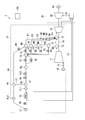
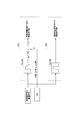
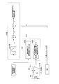
- FIG. 1 is a system diagram of a combined cycle power plant according to a first embodiment of the present invention.
- the gas turbine combined cycle power plant 1 of the present embodiment (hereinafter referred to as the power plant 1) includes a gas turbine 10, a steam turbine 20, and a rotor 16 of the gas turbine 10 and the steam turbine 20. And a controller 100 for controlling the power generation plant 1.
- the gas turbine 10 includes an IGV (inlet guide vane) 15 that adjusts an amount of air flowing in from an air inlet system 18, a compressor 11 that compresses the air to generate compressed air, and a casing 12 into which the compressed air flows.
- a combustor 13 for mixing the compressed air with the fuel gas and burning it to generate a high temperature combustion gas, a turbine 14 for rotating the rotor 16 by the combustion gas, a fuel tank P3 and a plurality of fuel systems F1 to F5;
- a fuel line L1 for supplying fuel to fuel systems F1 to F5 and a fuel line L0 for supplying fuel to fuel system F1 are provided.
- a valve V7, a pressure control valve V8, a safety valve V9 and a safety valve V10 are provided.
- the plurality of fuel systems F1 to F5 may be a pre-mixed pilot system F1, a diffusion pilot system F2, a main A system F3, a main B system F4, and a top hat system F5.
- the premixed pilot system F1 includes a fuel flow control valve V1 for adjusting the amount of fuel supplied from the fuel tank P3, a manifold PP for premixed pilot, and a fuel nozzle N1 connected to the manifold PP for premixed pilot.
- the diffusion pilot system F2 includes a fuel flow control valve V2 for adjusting the amount of fuel supplied from the fuel tank P3, a diffusion pilot manifold DP, and a fuel nozzle N2 connected to the diffusion pilot manifold DP.
- the main A system F3 includes a fuel flow control valve V3 for adjusting a fuel supply amount from the fuel tank P3, a main A manifold MA, and a fuel nozzle N3 connected to the main A manifold MA.
- the main B system F4 includes a fuel flow control valve V4 for adjusting a fuel supply amount from the fuel tank P3, a main B manifold MB, and a fuel nozzle N4 connected to the main B manifold MB.
- the top hat system F5 includes a fuel flow control valve V5 for adjusting the fuel supply amount from the fuel tank P3, a top hat manifold THA, and a fuel nozzle N5 connected to the top hat manifold THA.
- the premixed pilot system F1 performs premixed combustion to improve the reduction of NOx in the combustor 13.
- the diffusion pilot system F2 performs diffusion combustion to stabilize the flame.
- the main A system F3 and the main B system F4 are main fuel systems that supply a premixed gas according to the load size of the gas turbine 10.
- the top hat system F5 injects the fuel gas from the upstream side (the side of the vehicle interior 12) of the combustor 13 in order to improve the combustion efficiency and stabilize the flame.
- the control device 100 controls the amount of fuel supplied from the plurality of fuel systems F1 to F5 in accordance with the load and operating state of the gas turbine 10.
- the fuel line L0 is provided with a filter FL0, a drain outlet P0, and a fuel flow control valve V0 for adjusting the amount of fuel supplied to the pre-mix pilot manifold PP.
- the fuel line L0 is a characteristic configuration according to the gas turbine 10 of the present embodiment, but in order to bypass the fuel heating device 23, each valve, etc., compared to the fuel line L1, the fuel line L0 is the fuel passing through the fuel line L0. There is little pressure loss. Since the fuel passing through the fuel line L0 is not heated by the fuel heating device 23, its density is higher at low temperature than the fuel supplied via the fuel line L1.
- the fuel supplied from the fuel line L0 side is low temperature, high density, and high pressure as compared with the fuel supplied from the fuel line L1 side. Since the fuel supplied from the fuel line L0 has a relatively high density and high pressure, more fuel can be supplied from the fuel line L0 than to the fuel line L1.
- a line L3 connecting the drain discharge port P0 and the drain receiving port P1 is for discharging the drain to the fuel line L1 in order to prevent the fuel from accumulating in the fuel line L0.
- the flow rate of fuel supplied to the fuel line L1 through the line L3 is limited to a small amount.
- the fuel flow control valve V0 be provided at a position between the drain outlet P0 and the pre-mixing pilot manifold PP, and be provided as close to the pre-mixing pilot manifold PP as possible. For example, it may be provided at a position closer to the pre-mixing pilot manifold PP than the drain discharge port P0.
- the flow rate adjustment valve V0 may be provided at a position where the first distance and the second distance are substantially the same, or at a position where the first distance is shorter than the second distance. The reason why the fuel flow control valve V0 is preferably provided at a position close to the premix pilot manifold PP is to supply fuel quickly after the fuel flow control valve V0 is opened.
- the exhaust port of the turbine 14 is connected to an exhaust heat recovery boiler 21 of the steam turbine 20.
- the steam turbine 20 uses exhaust heat discharged from the turbine 14 to generate steam in the exhaust heat recovery boiler 21, and rotates the turbine 22 with the steam.
- the exhaust heat recovery boiler 21 and the above-described fuel heating device 23 are connected via a heating water supply line L2.
- the fuel heating device 23 raises the temperature of the fuel of 100 degrees or less to several hundred degrees in order to improve the thermal efficiency in the combustor 13. Heating water is supplied from the exhaust heat recovery boiler 21 to the fuel heating device 23 through the heating water supply line L2. In the fuel heating device 23, the heating water and the fuel flowing through the fuel line L1 exchange heat. At this time, heat is transferred from the heating water to the fuel, and the temperature of the fuel rises.
- a temperature sensor (not shown) is provided on the downstream side of the fuel heating device 23 (the downstream side in the direction in which the fuel flows), and the control device 100 controls the temperature of the fuel measured by the temperature sensor to be a desired temperature. Do.
- the temperature sensor is provided downstream of the drain receiving port P1 and temperature-controlled including the fuel flowing in from the line L3.
- a heat exchanger (not shown) for performing heat exchange between the heating water and the fuel and a bypass flow path of the fuel bypassing the heat exchanger are provided in the fuel heating device 23 ing.
- the control device 100 controls the temperature of the fuel to be within a predetermined range by switching the flow path of the fuel between the bypass flow path and the heat exchanger side.
- the fuel line L0 specific to the present embodiment bypasses the entire fuel line L1 (the fuel heating device 23 and various valves) and is connected to the manifold PP, unlike the heat exchanger bypass flow passage provided in the fuel heating device 23. Flow path.
- the fuel flowing through the fuel line L0 is not affected by the temperature control by the fuel heating device 23, and is not heated and does not become high temperature. Therefore, the density of the fuel flowing through the fuel line L0 is larger than the density of the fuel gas flowing through the fuel line L1.
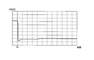
- FIG. 2 is a first diagram for explaining a general control method of fuel supply at the time of load interruption.
- FIG. 2 is a graph showing an example of the transition of the total fuel flow rate command value (CSO: control signal output) with the passage of time after load interruption.
- CSO total fuel flow rate command value
- the controller 100 instantaneously lowers the value of CSO in order to suppress the increase in the rotational speed of the gas turbine 10.
- the control device 100 adjusts the CSO so that the number of revolutions becomes a predetermined target value (for example, the number of revolutions approximately the same as that during rated operation).
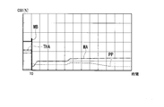
- FIG. 3 is a second diagram for explaining a general control method of fuel supply at the time of load interruption.
- An example of the breakdown of CSO shown in FIG. 2 is shown in FIG.
- the graph MA shows the proportion of fuel supplied to the main A system F3.
- the graph MB shows the proportion of fuel supplied to the main B system F4.
- the graph PP shows the proportion of fuel supplied to the pre-mixed pilot system F1.
- the graph THA shows the proportion of fuel supplied to the top hat system F5. Diffusion pilot system F2 is used at start-up and the like, and no fuel is supplied during operation.
- the control device 100 fully closes the fuel flow control valve V4 of the main B system F4 and the fuel flow control valve V5 of the top hat system F5 when the load interruption occurs at time T0.
- the opening degree of the fuel flow control valve V3 of the main A system F3 is throttled (graph MA), and the fuel flow control valve V1 of the pre-mixed pilot system F1 is fully opened (graph PP).
- graph MA The opening degree of the fuel flow control valve V3 of the main A system F3 is throttled
- graph PP the fuel flow control valve V1 of the pre-mixed pilot system F1 is fully opened
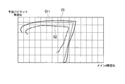
- FIG. 4 is a third diagram for explaining a general control method of fuel supply at the time of load interruption.
- Graph C1 and Graph C2 in FIG. 4 show the fuel-air ratio (pre-mixed pilot fuel-air ratio) of the fuel gas ejected by the fuel nozzle N1 of the pre-mixed pilot system F1 after load interruption and the fuel nozzle N3 of main A system F3.
- the relationship between the fuel-air ratio (main A fuel-air ratio) of the emitted fuel gas is shown.
- the graph Cri shows a value (fuel-air ratio criterion) as a threshold value for determining whether or not the flame in the pre-mixed pilot system F1 is misfired. If the pre-mixed pilot fuel-air ratio is at least one point and the fuel-air ratio criterion or more, misfires in the fuel nozzle N1 can be prevented.
- the fuel supplied from the main B system F4 the diffusion pilot system F2 and the top hat system F5 is set to 0, the fuel supplied from the main A system F3 is reduced, and the premixed pilot system F1 is supplied.
- control for maintaining the flame of the combustor 13 while suppressing the output of the gas turbine 10 is performed.
- the graph C1 shows that the pre-mixed pilot fuel / air ratio rises after load interruption and reaches the fuel / air ratio criterion. A misfire can be prevented if the fuel-air ratio as shown by the graph C1 can be realized between the two systems in which the fuel supply is continued after the load interruption.
- the pre-mixed pilot of graph C2 Since the value of the fuel / air ratio becomes equal to or less than the fuel / air ratio criterion (graph Cri), the possibility of the occurrence of misfire in the fuel nozzle N1 becomes high.
- the valve opening degree of the fuel flow control valve V1 and the fuel flow control valve V3 is calculated from the relationship between the mixed pilot fuel / air ratio and the main A fuel / air ratio.
- the controller 100 controls the fuel flow control valve V1 and the fuel flow control valve V3 based on the valve opening degree calculated in this manner.
- the fuel flow control valve V1 and the fuel flow control valve V3 after the load is interrupted according to the valve opening degree calculated by the above method. Even if the opening degree is controlled, the fuel supplied from the fuel nozzle N1 may be insufficient, and the pre-mixed pilot fuel / air ratio may not reach the fuel / air ratio criterion.
- the fuel line L0 for supplying a sufficient amount of fuel to the pre-mixed pilot system F1 after the load interruption is provided independently of the fuel line L1.
- the controller 100 closes the fuel flow control valve V0 during normal load operation (for example, 40% to 100% load) and does not supply fuel through the fuel line L0.
- the fuel flow control valve V0 of the fuel line L0 is opened. Then, high-density fuel is supplied to the premixed pilot system F1 while maintaining a relatively high supply pressure via the fuel line L0 having a pressure loss smaller than that of the fuel line L1.
- the control device 100 controls the fuel flow rate control valve even after the load is shut off so as to realize the fuel flow rate such that the relationship between the pre-mixed pilot fuel / air ratio and the main A fuel / air ratio is as shown by graph C1 in FIG. Adjust the opening of V0.
- FIG. 4 exemplifies the graph showing the relationship between the index relating to the pre-mixed pilot fuel-air ratio and the index relating to the main A fuel-air ratio
- the graph of FIG. It can be similarly expressed as a relationship with the calculated value of the flame temperature of the A system F3.
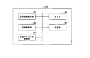
- FIG. 5 is a block diagram showing an example of a control device in the first embodiment according to the present invention.
- the control device 100 includes a load cutoff detection unit 101, a fuel control unit 102, a pre-mix bypass valve control unit 103, a timer 104, and a storage unit 105.
- the load cutoff detection unit 101 detects load cutoff.
- the load cutoff detection unit 101 acquires a load cutoff signal that disconnects the load during operation of the gas turbine 10.
- the fuel control unit 102 controls the amount of fuel injected from the fuel nozzles N1 to N5 via the fuel line L1.
- the fuel control unit 102 determines that the amount of fuel injected from the fuel nozzles N1 to N5 is set so that the rotational speed of the gas turbine 10 becomes equal to or less than a predetermined threshold. Control to be less than the supply amount of For example, when a load interruption occurs, the fuel control unit 102 fully closes the fuel flow control valves V2, V4, and V5 and throttles the opening degree of the fuel flow control valve V3 more than that during normal load operation. Control to fully open V1 for a predetermined time is performed.
- the pre-mixing bypass valve control unit 103 controls the fuel flow control valve V0 of the fuel line L0. Specifically, the preliminary mixing bypass valve control unit 103 fully closes the fuel flow control valve V0 during normal load operation.
- the premixed bypass valve control unit 103 controls the fuel flow control valve V0 from the closed state to the open state, and the premixed fuel gas from the fuel nozzle N1 in the combustor 13
- the opening degree of the fuel flow control valve V0 is adjusted so that the fuel-air ratio is equal to or higher than a predetermined fuel-air ratio (fuel-air ratio criterion) capable of avoiding the occurrence of a misfire.
- the timer 104 measures time.
- the storage unit 105 stores various information such as a function necessary for calculating the opening degree of the fuel flow control valve V0 to V5 after the load is interrupted.
- the control device 100 has various functions related to control of the gas turbine 10 and the steam turbine 20, but description of functions not related to the present embodiment will be omitted.
- FIG. 6 is a view for explaining a control method of fuel supplied to the pre-mixed pilot system in the first embodiment according to the present invention.
- the timer 104 measures an elapsed time after load interruption and outputs the measured time to the fuel control unit 102 and the pre-mix bypass valve control unit 103.
- the fuel control unit 102 calculates CSO based on the target load and the like after the load interruption.
- the fuel control unit 102 has, for example, a function Fx 102 that defines the valve opening degree of the fuel flow control valve V1 according to the elapsed time after load interruption, and the elapsed time after load interruption and the function obtained from the timer 104 Based on Fx102, the opening degree of the fuel flow control valve V1 is calculated.
- the fuel control unit 102 outputs a valve opening degree command value corresponding to the calculated opening degree of the fuel flow control valve V1.
- the function Fx102 indicates, for example, an opening degree that indicates that a predetermined value (for example, 0.5 seconds) between 0 and 1 seconds after the load is interrupted causes the fuel flow control valve V1 to be fully opened and then fully closed. Output. It is necessary to supply sufficient fuel to the fuel nozzle N1 of the premixed pilot system F1 for holding the flames of the combustor 13 by making the fuel flow control valve V1 fully open only for a predetermined period after the load interruption. This is to compensate for the delay until the required fuel flow rate is realized by opening the fuel flow control valve V0. The fuel control unit 102 fully opens the fuel flow control valve V1 so that the fuel supply amount supplied from the fuel nozzle N1 can be secured when the load is shut off.
- the pre-mixing bypass valve control unit 103 has, for example, a function Fx 103 for calculating a change index indicating a change in the required amount of fuel supply according to the elapsed time after load interruption, and the load interruption acquired from the timer 104 Based on the later elapsed time and the function Fx 103, a change index ⁇ of the fuel flow rate according to the elapsed time is calculated.
- the pre-mixing bypass valve control unit 103 calculates a fuel flow rate command value ⁇ obtained by multiplying the preliminary mixing pilot ratio by CSO indicating the total fuel flow rate necessary after the load interruption calculated by the fuel control unit 102.
- the pre-mixed pilot ratio is a value indicating how much of the total fuel flow rate is allocated to the pre-mixed pilot system F1 after the load is cut off.
- a main ratio indicating how much of the total fuel flow rate is to be allocated to the main A system F3 after load interruption is defined.
- the pre-mix bypass valve control unit 103 multiplies the change index ⁇ indicating the temporal change of the fuel flow rate by the fuel flow rate command value ⁇ , and is supplied through the fuel flow rate adjustment valve V0 according to the elapsed time after load interruption. A fuel flow rate command value ⁇ corresponding to the fuel supply amount is calculated. The pre-mixing bypass valve control unit 103 outputs a valve opening degree command value corresponding to the calculated fuel flow rate command value ⁇ .
- the fuel control unit 102 calculates the amount of fuel supplied from the main A system F3 after load interruption based on the elapsed time after load interruption, the function Fx 103, CSO, and the main ratio.
- the pre-mixed pilot fuel air ratio and the main A fuel air ratio are as shown in FIG. It is designed to satisfy the sky ratio criteria.
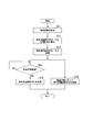
- FIG. 7 is a flowchart showing an example of control in the first embodiment according to the present invention.
- the flow of fuel supply control to the pre-mixed pilot system F1 at the time of load interruption in the present embodiment will be described using the flowchart of FIG. 7.
- the fuel control unit 102 closes the fuel flow control valve V0 and the fuel flow control valve V2 (diffusion pilot), and the fuel flow control valve V1 (premixed pilot), V3 (main A), With respect to V4 (main B) and V5 (top hat), the desired opening is controlled based on the distribution ratio of CSO and fuel to each fuel system (for example, time before T0 in FIG. 3).
- load interruption occurs in the power plant 1.
- the load shutoff detection unit 101 acquires a load shutoff signal and detects a load shutoff (step S11).
- the load shutoff detection unit 101 notifies the fuel control unit 102 and the pre-mix bypass valve control unit 103 of the occurrence of the load shutoff, and instructs the fuel supply control at the time of the load shutoff.
- the fuel control unit 102 calculates the initial opening degree after the load cutoff of the fuel flow control valve V1.
- the pre-mixing bypass valve control unit 103 calculates the initial opening degree of the fuel flow control valve V0 after the load is cut off (step S12). For example, the fuel control unit 102 calculates the opening degree of the fuel flow control valve V1 as 100%.
- the pre-mixing bypass valve control unit 103 calculates the opening degree of the fuel flow rate control valve V0 based on CSO, the distribution ratio to the pre-mixing pilot system F1, the function Fx 102, and the elapsed time as described in FIG. Do.
- the fuel control unit 102 outputs the valve opening degree command value (initial opening degree) calculated in step S12 to the fuel flow control valve V1.
- the pre-mixing bypass valve control unit 103 outputs the calculated valve opening degree command value (initial opening degree) to the fuel flow control valve V0 (step S13).
- relatively dense fuel having a desired flow rate is supplied through the fuel flow control valve V0.
- the fuel flow control valve V0 opens from a fully closed position to a predetermined opening degree, and there is a delay before fuel is supplied.
- the fuel to the pre-mixed pilot system F1 in the meantime Make up for the supply. By these controls, it is possible to prevent the misfire of the pre-mixed pilot system F1.
- the fuel control unit 102 opens the fuel flow control valve V3 at an opening based on a value obtained by multiplying CSO by the distribution ratio to the main A power system F3. , V4 and V5 are controlled to 0%.
- the fuel control unit 102 waits for a predetermined time (for example, 0.5 seconds) to elapse from the load interruption (step S14), and the fuel flow control valve V1 is fully operated. It is closed (step S15).
- the pre-mixing bypass valve control unit 103 controls the fuel-air ratio of the fuel injected from the pre-mixing pilot system F1 according to the elapsed time after load interruption measured by the timer 104 so that misfires can be avoided.
- the opening degree of the fuel flow control valve V0 is controlled to be equal to or higher than the ratio criterion (step S16).
- the method of calculating the opening degree of the fuel flow control valve V0 is as described in FIG.
- the pre-mixing bypass valve control unit 103 continues the control of step S16 after load disconnection, for example, until a predetermined time has elapsed.
- the relationship between the fuel / air ratio of the fuel injected from the main A system F3 and the fuel / air ratio of the fuel injected from the pre-mixed pilot system F1 becomes a relationship that can avoid the occurrence of misfires.
- the opening degree of the fuel flow control valve V3 is adjusted.
- the fuel control unit 102 continues the opening degree control of the fuel flow control valve V3 until, for example, a predetermined time has elapsed after the load is shut off.
- FIG. 8 is a first diagram showing an example of the opening control of the fuel control valve in the first embodiment according to the present invention.
- FIG. 8 shows the transition of the opening degree of the fuel flow control valve V0 by the processing of steps S12 to S13 and step S16 described above.
- the opening degree of the fuel flow control valve V0 is controlled as described with reference to FIG. 6 in order to prevent a misfire due to a rapid decrease in the fuel supply amount. Since high-density fuel is supplied from the fuel flow control valve V0 with a low pressure loss, it is possible to supply more fuel than the heated fuel through the fuel flow control valve V1. . Since it is necessary to supply the fuel to the fuel nozzle N1 as soon as possible after the load is shut off, the fuel flow control valve V0 is provided at a position close to the pre-mix pilot manifold PP as described with reference to FIG. Is desirable.
- FIG. 9 is a second diagram showing an example of the opening control of the fuel control valve in the first embodiment according to the present invention.
- FIG. 9 shows the transition of the opening degree of the fuel flow control valve V1 by the processing of steps S12 to S15 described above. As described above, while the fuel supply via the fuel flow control valve V0 is stabilized, the fuel flow control valve V1 is fully opened to compensate the fuel flow supplied from the pre-mixed pilot system F1.
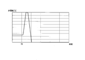
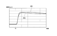
- FIG. 10 is a diagram for explaining the effect of control in the first embodiment according to the present invention.
- FIG. 10 shows changes in the flow rate of fuel supplied from the pre-mixed pilot system F1 before and after application of the control of the present embodiment.
- the vertical axis of the graph of FIG. 10 represents the fuel flow rate, and the horizontal axis represents time.
- the graph PP1 shows the fuel flow rate when the fuel supply to the premixed pilot system F1 through the fuel line L0 of the present embodiment is added.
- the graph PP2 shows the fuel flow rate by the conventional control in which the fuel supply to the pre-mixed pilot system F1 is not performed via the fuel line L0.
- FIG. 10 after load interruption occurs at time T0, it can be seen that the fuel flow rate indicated by the graph PP1 according to the present embodiment exceeds the fuel flow rate indicated by the graph PP2 by the conventional control.
- (1) low temperature fuel before fuel heating can be supplied to the pre-mixed pilot system F1 with (2) reduced pressure loss. That is, by the fuel line L0, (1) fuel with high density can be introduced at (2) high supply pressure. Therefore, fuel can be supplied to the fuel line L1 or more through the fuel line L0. Therefore, according to the control method of the present embodiment, the fuel flow from the fuel line L0 to the pre-mixed pilot system F1 is added immediately after the load is interrupted, thereby preventing a decrease in the fuel flow rate after the load is interrupted. Fuel can be secured. In addition, the flame of the pre-mixed pilot system F1 serving as a start fire can be stabilized to prevent a misfire. As a result, for example, even when the fuel supply pressure of the pressure supply system 17 is low, it is possible to suppress a misfire at the time of load interruption and make the operation after the load interruption successful.
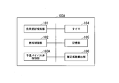
- FIG. 11 is a block diagram showing an example of a control device in the second embodiment according to the present invention.
- symbol is attached
- the control device 100A according to the second embodiment includes a correction coefficient calculation unit 106 in addition to the configuration of the first embodiment.
- the control device 100A includes a preliminary mixing bypass valve control unit 103A in place of the preliminary mixing bypass valve control unit 103.
- the correction coefficient calculation unit 106 sets the valve opening degree of the fuel flow control valve V0 calculated by the pre-mix bypass valve control unit 103A to an environmental condition indicating the state of air taken in by the gas turbine, such as atmospheric temperature, atmospheric pressure, and relative humidity. In accordance with this, a correction coefficient for correction is calculated.
- the correction coefficient calculation unit 106 corrects the valve opening degree of the fuel flow control valve V0 according to the fuel condition indicating the nature of the fuel such as the fuel calorie and the fuel density.
- the pre-mixing bypass valve control unit 103A calculates the corrected valve opening degree by multiplying the valve opening degree of the fuel flow control valve V0 calculated by the method of the first embodiment by the correction coefficient.
- the correction coefficient calculation unit 106 has a table (for example, Fx 1061 to Fx 1064 described later) in which the correction coefficient according to the environmental condition and the fuel condition is defined.
- FIG. 12 is a view for explaining a control method of fuel supplied to the pre-mixed pilot system in the first embodiment according to the present invention.
- the mass flow rate of air flowing into the compressor 11 changes with the ambient temperature. For example, when the ambient temperature rises, the density of the air decreases, and the mass flow rate of the air flowing into the compressor 11 decreases. If the mass flow rate of air decreases, the amount of air supplied to the combustor 13 decreases even if the same volume of air flows in, which affects the fuel / air ratio and the flame temperature.
- the valve opening degree of the fuel flow control valve V0 is corrected according to the ambient temperature, so that an appropriate fuel / air ratio can be realized.
- the correction coefficient calculation unit 106 acquires, for example, the atmospheric temperature in the vicinity of the air inlet system 18 from a temperature sensor (not shown) provided on the inlet side of the compressor 11.
- the correction coefficient calculation unit 106 calculates the correction coefficient K 1 of the valve opening degree corresponding to the acquired atmospheric temperature from the correction coefficient table Fx 1061.
- the horizontal axis of the correction coefficient table Fx 1061 is the air temperature, and the vertical axis is the correction coefficient of the valve opening degree. If the atmospheric temperature is high, the density of air flowing into the compressor 11 is reduced, and accordingly, the fuel flow rate also needs to be reduced. Therefore, as shown in the drawing, the correction coefficient table Fx 1061 is set so that the value of the correction coefficient K 1 becomes smaller as the atmospheric temperature becomes higher.
- Correction coefficient calculating unit 106 outputs the correction coefficient K 1 corresponding to the ambient temperature to a premixed bypass valve control unit 103A.
- the pre-mixing bypass valve control unit 103A obtains the elapsed time after load interruption from the timer 104, and uses the function Fx 103 to calculate the temporal change index ⁇ of the fuel flow rate according to the elapsed time after load interruption. Premixing the bypass valve control unit 103A calculates the variation index alpha 1 is multiplied by the correction coefficient K 1 to the variation index alpha.
- the correction coefficient calculation unit 106 may calculate a correction coefficient according to the atmospheric pressure, the fuel density, and the fuel calorie. For example, in the case of the atmospheric pressure, as shown in the correction coefficient table Fx 1062, the correction coefficient (vertical axis) is set to have a positive correlation with the atmospheric pressure (horizontal axis). Correction coefficient calculating unit 106, the correction coefficient table Fx1062, calculates the correction factor K 2 of the valve opening degree corresponding to the air pressure. Correction coefficient calculating unit 106 outputs the correction coefficient K 2 to the premixed bypass valve control unit 103A. Premixing the bypass valve control unit 103A calculates the variation index alpha 2 is multiplied by the correction factor K 2 in the change indicator alpha 1.
- correction coefficient table Fx 1063 As for the fuel calorie, as shown in the correction coefficient table Fx 1063, the correction coefficient (vertical axis) is set to have a negative correlation with the fuel calorie (horizontal axis).
- correction coefficient table Fx1064 As for the fuel density, as shown in the correction coefficient table Fx1064, the correction coefficient (vertical axis) is set to have a negative correlation with the fuel density (horizontal axis).
- Correction coefficient calculating unit 106 calculates a correction coefficient K 4 of the valve opening degree corresponding to the fuel density. Premixing the bypass valve control unit 103A calculates the correction coefficient K 4 to multiplying by change index alpha 4 to change the index alpha 3.
- Premixing the bypass valve control unit 103A multiplies the change index alpha 4 and the fuel flow rate command value beta, calculates a fuel flow rate command value ⁇ 'with the elapse time after load rejection.
- the pre-mixing bypass valve control unit 103A outputs a valve opening degree command value for the fuel flow control valve V0 corresponding to the calculated fuel flow rate command value ⁇ '.
- FIG. 12 illustrates the case where the correction coefficient for the fuel flow control valve V0 is calculated based on the above four parameters
- the present invention is not limited to this.
- the correction coefficient calculation unit 106 may further calculate a correction coefficient according to the atmospheric humidity.
- the correction coefficient calculation unit 106 is not limited to the embodiment that calculates the correction coefficient for all the parameters described above, and the correction coefficient calculation unit 106 may select one or more of the atmospheric temperature, the atmospheric pressure, the atmospheric humidity, the fuel density, and the fuel calorie.
- the preliminary mixing bypass valve control unit 103A may be configured to calculate the valve opening degree command value of the fuel flow control valve V0 by multiplying the change index ⁇ by the correction coefficient of the fuel mixing control valve 103 .
- the fuel control unit 102 may calculate the valve opening degree of the fuel flow control valve V3 of the main A system F3 by multiplying the correction coefficient calculated by the correction coefficient calculation unit 106.
- valve opening degree command value of the fuel flow control valve V0 is corrected according to the air temperature and the like described with reference to FIG. 12 in the processes of steps S12 and S16.
- the flow of the entire processing and the processing in the other steps are the same as in the first embodiment.
- the present embodiment it is possible to calculate the opening degree of the fuel flow control valve V0 according to the atmospheric temperature, the atmospheric pressure, the fuel calorie and the like. As a result, it is possible to properly respond to various environmental conditions and fuel conditions at the time of load interruption and to prevent misfire more reliably.
- FIG. 13 is a block diagram showing an example of a control device in the third embodiment according to the present invention.
- symbol is attached
- the control device 100B according to the third embodiment includes a learning unit 107 in addition to the configuration of the first embodiment.
- the learning unit 107 has a function of adjusting the valve opening degree of the fuel flow control valve V0 calculated by the preliminary mixing bypass valve control unit 103B in accordance with the actual operation of the gas turbine 10. For example, the learning unit 107 adjusts the adjustment coefficient k based on the relationship between the actual premixed pilot fuel-air ratio and the main A fuel-air ratio and the deviation between the fuel-air ratio criteria illustrated in FIG. (T) is learned (learning function 107b). The learning unit 107 outputs the adjustment coefficient k (t) learned when the load interruption occurs next to the premixed bypass valve control unit 103B (adjustment function 107a). The pre-mixing bypass valve control unit 103B multiplies the valve opening degree calculated by the method of the first embodiment by the adjustment coefficient k (t) to calculate the valve opening degree after adjustment.
- FIG. 14 is a view for explaining a control method of fuel supplied to the pre-mixed pilot system in the third embodiment according to the present invention.
- the learning function 107 b of the learning unit 107 will be described.
- the learning unit 107 calculates the preliminary mixed pilot fuel / air ratio and the fuel / air ratio of the main A each time a load interruption occurs. For example, the learning unit 107 calculates the fuel flow rate to the fuel nozzle N1 from the measurement values of the pressure sensor on the upstream side and the pressure sensor on the downstream side of the fuel nozzle N1. For example, the learning unit 107 calculates the air flow rate to the fuel nozzle N1 based on the opening degree of the IGV 15, the atmospheric temperature, the atmospheric pressure, and the like. The learning unit 107 divides the fuel flow rate to the fuel nozzle N1 by the air flow rate to the fuel nozzle N1 to calculate a fuel-air ratio (premixed pilot fuel-air ratio) corresponding to the fuel nozzle N1.
- the learning unit 107 calculates the fuel flow rate to the fuel nozzle N3 from the measurement values of the pressure sensors on the upstream and downstream sides of the fuel nozzle N3, and based on the opening degree of the IGV 15, etc., the fuel nozzle N3. Calculate the air flow to The learning unit 107 divides the fuel flow rate to the fuel nozzle N3 by the air flow rate to the fuel nozzle N3 to calculate the fuel-air ratio (main A fuel-air ratio) corresponding to the fuel nozzle N3. The learning unit 107 records the relationship between the actual main A fuel-air ratio and the pre-mixed pilot fuel-air ratio in the storage unit 105 (graph C3 in FIG. 14).
- the learning unit 107 compares the fuel-air ratio criteria Cri prepared in advance with the graph C3, and when the preliminary mixed pilot fuel-air ratio does not reach the fuel-air ratio criteria Cri, calculates the deviation.
- the learning unit 107 calculates a deviation ⁇ C for each elapsed time after load interruption and records the deviation ⁇ C in the storage unit 105 in association with the elapsed time.
- the learning unit 107 learns the adjustment coefficient at each time, for example, by the following equation (1).
- k (t) new k (t) now + K ⁇ (Actual pilot pilot fuel / air ratio (t)-Target pilot pilot fuel / air ratio (t)) ...
- t is an elapsed time from load shedding
- k (t) new is a new adjustment coefficient at the elapsed time t after learning
- k (t) now is the latest adjustment coefficient before learning at the elapsed time t
- K is The predetermined constant that determines the effectiveness of learning
- the actual pilot pilot fuel / air ratio (t) is the pilot pilot fuel / air ratio calculated by the above procedure at time t
- the target pilot pilot fuel / air ratio (t) is the actual The value of the pilot pilot fuel / air ratio of the pilot fuel / air ratio criteria Cri corresponding to the pilot pilot fuel / air ratio (t) and the actual main fuel A ratio (t) (the actual main fuel A ratio (t) and It is the Y axis value of the graph Cri at the position having the same value in the X axis direction).
- the adjustment coefficient k (t) it is possible to obtain an adjustment coefficient for maintaining the pre-mixed pilot fuel / air ratio reaching the fuel / air ratio criteria.
- the adjustment function 107 a of the learning unit 107 will be described.
- the learning unit 107 refers to the storage unit 105 and reads out and acquires the latest adjustment coefficient k (t) obtained as a result of learning based on the elapsed time measured by the timer 104. .
- the learning unit 107 outputs the acquired adjustment coefficient k (t) to the premixed bypass valve control unit 103B.
- the pre-mixing bypass valve control unit 103B obtains the elapsed time after load interruption, and uses the function Fx 103 to calculate the change index ⁇ of the fuel flow rate according to the elapsed time after load interruption.
- the premixed bypass valve control unit 103B multiplies the change index ⁇ by the adjustment coefficient k (t) for each elapsed time to calculate the change index ⁇ ′ ′.
- the pre-mixing bypass valve control unit 103B multiplies the change index ⁇ ′ ′ by the fuel flow rate command value ⁇ to calculate a fuel flow rate command value ⁇ ′ ′ according to the elapsed time after load interruption.
- the pre-mixing bypass valve control unit 103B outputs a valve opening degree command value for the fuel flow control valve V0 corresponding to the calculated fuel flow rate command value ⁇ ′ ′.
- the pre-mixing bypass valve control unit 103B further multiplies the correction coefficient according to the atmospheric temperature, atmospheric pressure, atmospheric humidity, fuel density, fuel calorie, etc. calculated by the correction coefficient calculation unit 106 of the second embodiment, and adjusts the fuel flow rate.
- the valve opening degree command value for the valve V0 can be corrected in accordance with the environmental condition and the fuel condition.
- valve opening degree command value of the fuel flow control valve V0 is corrected by the adjustment coefficient described with reference to FIG. 14 in the processing of step S12 and step S16.
- the flow of the entire processing and the processing in the other steps are the same as in the first embodiment.
- the flow of processing of the learning function 107b will be described.
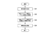
- FIG. 15 is a flowchart showing an example of learning processing of the valve opening degree adjustment coefficient in the third embodiment according to the present invention.
- the load shutoff detection unit 101 detects a load shutoff (step S21).
- the pre-mixing bypass valve control unit 103B starts control of the fuel flow control valve V0 described with reference to FIG.
- the learning unit 107 calculates the preliminary mixed pilot fuel / air ratio and the main A fuel / air ratio for each predetermined time, and records the same in the storage unit 105 (step S22).
- the process of step S22 is performed in parallel with the processes of steps S12 and S16.
- the subsequent processing is performed in parallel with the processing of step S12 and step S16 or after operation at the time of load interruption.
- the learning unit 107 calculates the deviation ⁇ C between the target value of the pre-mixed pilot ratio indicated by the fuel-air ratio criteria recorded in the storage unit 105 and the pre-mixed pilot ratio for each elapsed time after load interruption recorded in step S22. Is calculated (step S23).
- the learning unit 107 updates the adjustment coefficient k (t) by the above equation (1) (step S24).
- the deviation ⁇ C between the actual premixed pilot fuel-air ratio and the target premixed pilot fuel-air ratio is the deviation between the calculated value of the actual premixed pilot flame temperature and the calculated value of the target premixed pilot flame temperature May be.
- a value based on the actual premixed pilot fuel / air ratio and the actual temperature of the passenger compartment 12 for example, the output value of a function having the pilot fuel / air ratio and the temperature of the passenger compartment 12 as input values
- its target value It may be a deviation from
- the adjustment coefficient for realizing the more optimal opening degree of the fuel flow rate adjustment valve V0 each time the load cutoff is performed and to reduce the possibility of misfire. it can. For example, by learning adjustment coefficients that reflect plant characteristics such as aging of the power plant 1 and operating environment and load conditions, etc., it is possible to more appropriately control the operation after load interruption while avoiding misfires. it can.
- the fuel supply to the pre-mixed pilot system F1 through the fuel line L0 and the fuel line L1 is performed at the time of load interruption, but the application destination of each embodiment is It is not limited to load shedding.
- it can be used in combination with control to reduce the amount of supplied fuel in operation to reduce load rapidly.
- the rapid load reduction is, for example, when the load reduction rate of the gas turbine 10 is higher than 100% per minute.
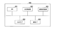
- FIG. 16 is a diagram showing an example of a hardware configuration of a control device in each embodiment of the present invention.
- the computer 900 is, for example, a PC (Personal Computer) or a server terminal device including a CPU 901, a main storage device 902, an auxiliary storage device 903, an input / output interface 904, and a communication interface 905.
- the control devices 100, 100A, 100B described above are implemented in the computer 900.
- the operation of each processing unit described above is stored in the auxiliary storage device 903 in the form of a program.
- the CPU 901 reads a program from the auxiliary storage device 903 and develops the program in the main storage device 902, and executes the above processing according to the program.
- the CPU 901 secures a storage area corresponding to the storage unit 105 in the main storage unit 902 according to the program.
- the CPU 901 secures a storage area for storing data being processed in the auxiliary storage device 903 according to a program.
- secondary storage 903 is an example of a non-transitory tangible medium.
- non-transitory tangible media include magnetic disks connected via an input / output interface 904, magneto-optical disks, CD-ROMs, DVD-ROMs, semiconductor memories, and the like.
- the distributed computer 900 may expand the program in the main storage unit 902 and execute the above processing.
- the program may be for realizing a part of the functions described above.
- the program may be a so-called difference file (difference program) that realizes the above-described function in combination with other programs already stored in the auxiliary storage device 903.
- a part may be realized using hardware such as a microcomputer, a large scale integration (LSI), an application specific integrated circuit (ASIC), a programmable logic device (PLD), or a field-programmable gate array (FPGA).
- LSI large scale integration
- ASIC application specific integrated circuit
- PLD programmable logic device
- FPGA field-programmable gate array
- the first nozzle is an example of a fuel nozzle N1
- the second nozzle is an example of a fuel nozzle N3
- the fuel line L1 is an example of a fuel supply channel
- the fuel line L0 is an example of a bypass channel
- the fuel flow control valve V0 is a bypass fuel flow
- the fuel flow control valve V1 is an example of a first fuel flow control valve
- the fuel / air ratio criteria is information indicating the relationship between the fuel / air ratio of the first nozzle causing the misfire and the fuel / air ratio of the second nozzle.
- An example of The line L3 is an example of a drain discharge channel.
- the fuel supply system includes the control device 100, a fuel line L0, a fuel line L1, and fuel systems F1 to F5.
- the necessary fuel supply amount is secured even when the fuel supply amount is reduced when the load of the gas turbine is reduced rapidly, It can prevent.
- 1 gas turbine combined cycle power plant 100, 100A, 100B control device, 101 load cutoff detection unit, 102 fuel control unit, 103, 103A, 103B preliminary mixed bypass valve control unit, 104 timer, 105 storage unit, 106 correction coefficient calculation Department 107 learning part 10 gas turbine 11 compressor 12 cabin 13 combustor 14 turbine 15 IGV 16 rotor 17 pressure supply system 18 air inlet system 20 steam turbine 21 exhaust heat recovery boiler , 22 turbine, 23 fuel heating device, 40 generator, P3 fuel tank, L0, L1 fuel line, L3 line, V6 shutoff valve, P0 drain outlet, P1 drain inlet, P2 shutoff valve outlet, V7 pressure regulating valve, V8 pressure regulator, V9 safety , V10 safety valve, FL0, FL1 filter, F1 pre-mixed pilot system, F2 diffusion pilot system, F3 main A system, F4 main B system, F5 top hat system, PP pre-mixed pilot manifold, DP diffusion pilot manifold, MA main Manifold for A, manifold
Abstract
ガスタービン燃料供給システムは、燃料を加熱する燃料加熱装置を備え、前記燃料加熱装置によって加熱された前記燃料を第1ノズル及び第2ノズルに供給する燃料供給流路と、前記燃料供給流路を介さずに前記第1ノズルに前記燃料を供給するバイパス流路と、前記バイパス流路を流れる前記燃料の流量を調節するバイパス燃料流量調節弁と、を備える。
Description
本発明は、燃料供給システム、ガスタービン、発電プラント、制御方法及びプログラムに関する。
本願は、2018年1月12日に、日本に出願された特願2018-003422号に基づき優先権を主張し、その内容をここに援用する。
本願は、2018年1月12日に、日本に出願された特願2018-003422号に基づき優先権を主張し、その内容をここに援用する。
ガスタービンと、ガスタービンから排出される排熱を利用して生成した蒸気を利用して蒸気タービンとを駆動させ発電を行うGTCC(ガスタービンコンバインドサイクル)発電プラントが提供されている。このような発電プラントの運転中に非常事態が生じた場合、負荷を切り離して運転を継続する負荷遮断と呼ばれる運用を行うことがある。負荷遮断を行うと、ガスタービンの回転数が上昇する。このとき、回転数の過度な上昇を防ぐため、燃焼器に供給する燃料を急速に低下させ、回転数を所定の閾値以下に抑制する制御が行われる場合がある。ガスタービンには、役割の異なる複数の燃料供給系統を有するものがある。複数の燃料供給系統を有するガスタービンでは、負荷遮断時に燃料供給量を急速に低下させるときにも、燃焼器の失火を防ぐために、種火となる火炎を供給するパイロット系統に対する燃料供給量を増加させる制御を行うことがある。
関連する技術として、特許文献1には、パイロット系統の燃料供給量を調節する弁の上流側に燃料貯蔵部を設け、この燃料貯蔵部に気体の燃料を予め貯蔵しておき、ガスタービンの始動時や負荷遮断時に燃料貯蔵部から燃料を供給して、パイロット系統に供給される燃料を増加させる制御方法が記載されている。
近年、コスト削減の要請等により、燃焼器に供給する燃料の供給圧が低い圧力に制限されることがある。このような設備で負荷遮断が生じると、パイロット系統に対する燃料供給量を増加させようとしても、元々の燃料の供給圧力が十分ではない為に、火炎を保つのに十分な燃料が供給されない可能性がある。
本発明は、上述の課題を解決することのできる燃料供給システム、ガスタービン、発電プラント、制御方法及びプログラムを提供する。
本発明の一態様によれば、燃料供給システムは、ガスタービンの燃料を加熱する燃料加熱装置を備え、前記燃料加熱装置によって加熱された前記燃料を第1ノズル及び第2ノズルに供給する燃料供給流路と、前記燃料供給流路を介さずに前記第1ノズルに前記燃料を供給するバイパス流路と、前記バイパス流路を流れる前記燃料の流量を調節するバイパス燃料流量調節弁と、を備える。
本発明の一態様によれば、前記燃料供給システムにおいて、前記バイパス流路を介して前記第1ノズルに供給される燃料の密度が、前記燃料供給流路を介して前記第1ノズルに供給される燃料の密度よりも高い。
本発明の一態様によれば、前記燃料供給システムにおいて、前記バイパス流路の圧力損失が、前記燃料供給流路の圧力損失よりも少ない。
本発明の一態様によれば、前記燃料供給システムにおいて、前記バイパス流路と前記燃料供給流路とを接続するドレンの排出流路がさらに設けられる。
本発明の一態様によれば、前記バイパス燃料流量調節弁が、前記バイパス流路における前記排出流路の接続位置と前記第1ノズルが接続されたマニホールドの間に設けられる。
本発明の一態様によれば、前記バイパス燃料流量調節弁が、前記排出流路の接続位置よりも前記マニホールドに近い位置に設けられる。
本発明の一態様によれば、前記燃料供給システムにおいて、前記バイパス燃料流量調節弁と前記第1ノズルが接続されたマニホールドとの間の配管距離を第1距離、前記燃料供給流路に設けられ前記第1ノズルへ供給される燃料の流量を調節する第1燃料流量調節弁と前記マニホールドとの間の配管距離を第2距離とすると、前記バイパス燃料流量調節弁が、前記第1距離が前記第2距離以下となる位置に設けられる。
本発明の一態様によれば、前記燃料供給システムは、前記バイパス燃料流量調節弁の開度を調節する制御装置、をさらに備える。
本発明の一態様によれば、前記燃料供給流路には、前記第1ノズルへ供給される燃料流量を調節する第1燃料流量調節弁が設けられ、前記制御装置は、前記ガスタービンの負荷低下の時に前記第1燃料流量調節弁および前記バイパス燃料流量調節弁を、前記負荷低下の前よりも大きな開度で開く。
本発明の一態様によれば、前記制御装置は、前記負荷低下の時に、前記第1燃料流量調節弁を所定の時間だけ全開とし、前記負荷低下の前は閉状態の前記バイパス燃料流量調節弁を所定の開度に開く制御を行う。
本発明の一態様によれば、前記制御装置は、前記負荷低下の後の前記バイパス燃料流量調節弁の開度を、前記負荷低下の後の経過時間に応じて定められた燃料流量の変化指標に基づいて制御する。
本発明の一態様によれば、前記制御装置は、前記負荷低下の時の前記第1ノズルの燃空比および前記第2ノズルの燃空比と、失火が生じる前記第1ノズルの燃空比および前記第2ノズルの燃空比の関係を示す情報とに基づいて、前記バイパス燃料流量調節弁の開度を調整する係数を学習する。
本発明の一態様によれば、前記制御装置は、前記ガスタービンが吸入する空気の状態を示す環境条件に基づいて、前記バイパス燃料流量調節弁の開度を補正する。
本発明の一態様によれば、前記制御装置は、前記燃料の性質を示す燃料条件に基づいて、前記バイパス燃料流量調節弁の開度を補正する。
本発明の一態様によれば、燃料供給システムは、ガスタービンの通常の負荷運転時に燃料を第1ノズル及び第2ノズルに供給する燃料供給流路と、前記燃料供給流路を介さずに前記第1ノズルに前記燃料を供給するバイパス流路と、前記バイパス流路を流れる前記燃料の流量を調節するバイパス燃料流量調節弁と、を備え、前記通常の負荷運転時は、前記バイパス燃料流量調節弁が閉とされ、前記通常の負荷運転時より負荷を低下させる時に前記バイパス燃料流量調節弁が開とされる。
本発明の一態様によれば、ガスタービンは、圧縮機と、燃焼器と、タービンと、上記の何れかに記載の燃料供給システムと、を備える。
本発明の一態様によれば、発電プラントは、上記のガスタービンと、蒸気タービンと、発電機と、を備える。
本発明の一態様によれば、制御方法は、ガスタービンの燃料を加熱する燃料加熱装置を備え、前記燃料加熱装置によって加熱された燃料を第1ノズル及び第2ノズルに供給する燃料供給流路と、前記燃料供給流路を介さずに前記第1ノズルに前記燃料を供給するバイパス流路と、前記バイパス流路を流れる前記燃料の流量を調節するバイパス燃料流量調節弁と、を備える燃料供給システムにおいて、前記ガスタービンの負荷低下の時に、前記バイパス燃料流量調節弁を閉から開へ制御する。
本発明の一態様によれば、プログラムは、ガスタービンの燃料を加熱する燃料加熱装置を備え、前記燃料加熱装置によって加熱された燃料を第1ノズル及び第2ノズルに供給する燃料供給流路と、前記燃料供給流路を介さずに前記第1ノズルに前記燃料を供給するバイパス流路と、前記バイパス流路を流れる前記燃料の流量を調節するバイパス燃料流量調節弁と、を備える燃料供給システムの制御装置のコンピュータを、前記ガスタービンの負荷低下の時に、前記バイパス燃料流量調節弁を閉から開へ制御する手段、として機能させる。
上記した燃料供給システム、ガスタービン、発電プラント、制御方法及びプログラムによれば、ガスタービンの負荷を急速に低下させるにあたって燃料供給量を低下させる場面でも、必要な燃料供給量を確保し、失火を防ぐことができる。
<第一実施形態>
以下、本発明の第一実施形態による負荷遮断時の制御方法について図1~図10を参照して説明する。
図1は、本発明に係る第一実施形態におけるコンバインドサイクル発電プラントの系統図である。
本実施形態のガスタービンコンバインドサイクル発電プラント1(以下、発電プラント1と記載する)は、図1に示すように、ガスタービン10と、蒸気タービン20と、ガスタービン10および蒸気タービン20のロータ16に接続して設けられた発電機40と、発電プラント1を制御する制御装置100と、を備えている。
以下、本発明の第一実施形態による負荷遮断時の制御方法について図1~図10を参照して説明する。
図1は、本発明に係る第一実施形態におけるコンバインドサイクル発電プラントの系統図である。
本実施形態のガスタービンコンバインドサイクル発電プラント1(以下、発電プラント1と記載する)は、図1に示すように、ガスタービン10と、蒸気タービン20と、ガスタービン10および蒸気タービン20のロータ16に接続して設けられた発電機40と、発電プラント1を制御する制御装置100と、を備えている。
ガスタービン10は、空気入口系統18から流入する空気量を調整するIGV(inlet guide vane)15と、空気を圧縮して圧縮空気を生成する圧縮機11と、圧縮空気が流入する車室12と、圧縮空気に燃料ガスを混合して燃焼させ高温の燃焼ガスを生成する燃焼器13と、燃焼ガスによりロータ16を回転駆動するタービン14と、燃料タンクP3および複数の燃料系統F1~F5と、燃料系統F1~F5に燃料を供給する燃料ラインL1と、燃料系統F1に燃料を供給する燃料ラインL0等を備える。燃料ラインL1には、遮断弁V6、フィルターFL1、ドレン受入口P1、遮断弁出口P2、燃料加熱装置(FGH:Fuel Gas Heater)23、圧力供給系統17が供給する燃料供給圧を制御する圧力調節弁V7及び圧力調節弁V8、安全弁V9及び安全弁V10が設けられている。
複数の燃料系統F1~F5はそれぞれ、予混パイロット系統F1、拡散パイロット系統F2、メインA系統F3、メインB系統F4、トップハット系統F5であってよい。予混パイロット系統F1には、燃料タンクP3からの燃料供給量を調整する燃料流量調節弁V1、予混パイロット用マニホールドPP、予混パイロット用マニホールドPPに接続された燃料ノズルN1が含まれる。拡散パイロット系統F2には、燃料タンクP3からの燃料供給量を調整する燃料流量調節弁V2、拡散パイロット用マニホールドDP、拡散パイロット用マニホールドDPに接続された燃料ノズルN2が含まれる。メインA系統F3には、燃料タンクP3からの燃料供給量を調整する燃料流量調節弁V3、メインA用マニホールドMA、メインA用マニホールドMAに接続された燃料ノズルN3が含まれる。メインB系統F4には、燃料タンクP3からの燃料供給量を調整する燃料流量調節弁V4、メインB用マニホールドMB、メインB用マニホールドMBに接続された燃料ノズルN4が含まれる。トップハット系統F5には、燃料タンクP3からの燃料供給量を調整する燃料流量調節弁V5、トップハット用マニホールドTHA、トップハット用マニホールドTHAに接続された燃料ノズルN5が含まれている。
予混パイロット系統F1は、予混合燃焼を行って燃焼器13の低NOx化を向上する。拡散パイロット系統F2は、拡散燃焼を行って火炎の安定化を図る。メインA系統F3、メインB系統F4は、ガスタービン10の負荷の大きさに応じた予混ガスを供給する主力の燃料系統である。トップハット系統F5は、燃焼効率の向上や火炎の安定化を図るため、燃焼器13の上流(車室12側)から燃料ガスを噴射する。制御装置100は、ガスタービン10の負荷や運転状態に応じて、これら複数の燃料系統F1~F5から供給する燃料供給量を制御する。
燃料ラインL0には、フィルターFL0、ドレン排出口P0、予混パイロット用マニホールドPPへ供給する燃料供給量を調節する燃料流量調節弁V0が設けられている。燃料ラインL0は、本実施形態のガスタービン10に係る特徴的な構成であるが、燃料加熱装置23や各バルブ等をバイパスする為、燃料ラインL1と比較すると、燃料ラインL0を通過する燃料には圧力損失が少ない。燃料ラインL0を通過する燃料は、燃料加熱装置23によって加熱されることが無いため、燃料ラインL1を介して供給される燃料に比べ低温で密度が高い。つまり、予混パイロット用マニホールドPPへは、燃料ラインL0を通過し燃料流量調節弁V0で流量が調節される燃料と、燃料ラインL1を通過し燃料流量調節弁V1で流量が調節される燃料の2つの系統からの燃料が供給されるが、燃料ラインL0側から供給される燃料は、燃料ラインL1側から供給される燃料に比べ低温、高密度、高圧である。燃料ラインL0側から供給される燃料が相対的に高密度、高圧であることにより、燃料ラインL0側からは、燃料ラインL1側に比べより多くの燃料を供給することができる。
ドレン排出口P0とドレン受入口P1を接続するラインL3は、燃料ラインL0に燃料が溜まるのを防ぐためにドレンを燃料ラインL1へ排出するためのものである。ラインL3を通過して燃料ラインL1へ供給される燃料の流量は微量に制限されている。
燃料流量調節弁V0は、ドレン排出口P0と予混パイロット用マニホールドPPとの間に位置に設けられ、できるだけ予混パイロット用マニホールドPPに近い位置に設けられることが好ましく、燃料流量調節弁V0は、例えば、ドレン排出口P0よりも予混パイロット用マニホールドPPに近い位置に設けられてもよい。燃料流量調節弁V0と予混パイロット用マニホールドPPとの間の配管距離を第1距離、燃料流量調節弁V1と予混パイロット用マニホールドPPとの間の配管距離を第2距離、とすると、燃料流量調節弁V0は、第1距離と第2距離が同程度となる位置、あるいは、第1距離が前記第2距離より短くなる位置に設けられていてもよい。燃料流量調節弁V0が予混パイロット用マニホールドPPに近い位置に設けられることが好ましい理由は、燃料流量調節弁V0を開としてから速やかに燃料を供給するためである。
タービン14の排気口は蒸気タービン20の排熱回収ボイラー21と接続されている。
蒸気タービン20は、タービン14から排出される排熱を利用して排熱回収ボイラー21で蒸気を生成し、この蒸気でタービン22を回転駆動させる。
蒸気タービン20は、タービン14から排出される排熱を利用して排熱回収ボイラー21で蒸気を生成し、この蒸気でタービン22を回転駆動させる。
排熱回収ボイラー21と上述の燃料加熱装置23とは加熱水供給ラインL2を介して接続されている。燃料加熱装置23は、燃焼器13における熱効率の向上のため、100度以下の燃料の温度を数100度に上昇させる。燃料加熱装置23へは、排熱回収ボイラー21から加熱水が加熱水供給ラインL2を通過して供給される。燃料加熱装置23では、この加熱水と、燃料ラインL1を流れる燃料とが熱交換を行う。このとき、加熱水から燃料へと熱が移動し、燃料の温度が上昇する。燃料加熱装置23の下流側(燃料が流れる方向の下流側)には、図示しない温度センサが設けられ、制御装置100は、温度センサが計測する燃料の温度が、所望の温度となるように制御する。温度センサは、ドレン受入口P1の下流側に設けられ、ラインL3から流入する燃料を含んで温度制御される。
具体的には、燃料加熱装置23の内部には、加熱水と燃料が熱交換を行うための熱交換器(図示せず)と、この熱交換器をバイパスする燃料のバイパス流路が設けられている。制御装置100は、燃料の流路を、バイパス流路と熱交換器側との間で切り替えることにより、燃料の温度が所定の範囲内となるよう制御する。本実施形態に特有の燃料ラインL0は、燃料加熱装置23が備える熱交換器のバイパス流路とは異なり、燃料ラインL1全体(燃料加熱装置23および各種バルブ類)をバイパスし、マニホールドPPへ接続される流路である。燃料ラインL0を流れる燃料は、燃料加熱装置23による温度制御の影響下には無く、加熱され高温となることがない。従って、燃料ラインL0を流れる燃料の密度は、燃料ラインL1を流れる燃料ガスの密度よりも大きい。
次に図1を参照しつつ、図2~図4を用いて一般的な負荷遮断時における燃料供給制御の一例を説明する。一般的なガスタービンは、燃料ラインL0を備えていない。
図2は、負荷遮断時の一般的な燃料供給の制御方法を説明する第1の図である。
図2は、負荷遮断後の時間の経過に伴う、全燃料流量指令値(CSO:control signal output)の推移の一例を示したグラフである。図示するように時刻T0に負荷遮断が発生すると、制御装置100は、ガスタービン10の回転数の上昇を抑えるためにCSOの値を瞬時に低下させる。その後は、制御装置100は、回転数が所定の目標値(例えば、定格運転時と同程度の回転数)となるようにCSOを調整する。
図2は、負荷遮断時の一般的な燃料供給の制御方法を説明する第1の図である。
図2は、負荷遮断後の時間の経過に伴う、全燃料流量指令値(CSO:control signal output)の推移の一例を示したグラフである。図示するように時刻T0に負荷遮断が発生すると、制御装置100は、ガスタービン10の回転数の上昇を抑えるためにCSOの値を瞬時に低下させる。その後は、制御装置100は、回転数が所定の目標値(例えば、定格運転時と同程度の回転数)となるようにCSOを調整する。
図3は、負荷遮断時の一般的な燃料供給の制御方法を説明する第2の図である。
図3に図2で示したCSOの内訳の一例を示す。グラフMAは、メインA系統F3に供給される燃料の割合を示す。グラフMBは、メインB系統F4に供給される燃料の割合を示す。グラフPPは、予混パイロット系統F1に供給される燃料の割合を示す。グラフTHAは、トップハット系統F5に供給される燃料の割合を示す。拡散パイロット系統F2は、起動時等に用いられ運転中は燃料が供給されない。図示するように制御装置100は、時刻T0に負荷遮断が生じると、メインB系統F4の燃料流量調節弁V4と、トップハット系統F5の燃料流量調節弁V5とを全閉とする。メインA系統F3の燃料流量調節弁V3の開度を絞り(グラフMA)、予混パイロット系統F1の燃料流量調節弁V1を全開とする(グラフPP)。これにより燃焼器13への燃料供給量を低下させて回転数を抑制しつつ、予混パイロット系統F1の燃料を増加させ、燃焼器13の種火を維持する。
図3に図2で示したCSOの内訳の一例を示す。グラフMAは、メインA系統F3に供給される燃料の割合を示す。グラフMBは、メインB系統F4に供給される燃料の割合を示す。グラフPPは、予混パイロット系統F1に供給される燃料の割合を示す。グラフTHAは、トップハット系統F5に供給される燃料の割合を示す。拡散パイロット系統F2は、起動時等に用いられ運転中は燃料が供給されない。図示するように制御装置100は、時刻T0に負荷遮断が生じると、メインB系統F4の燃料流量調節弁V4と、トップハット系統F5の燃料流量調節弁V5とを全閉とする。メインA系統F3の燃料流量調節弁V3の開度を絞り(グラフMA)、予混パイロット系統F1の燃料流量調節弁V1を全開とする(グラフPP)。これにより燃焼器13への燃料供給量を低下させて回転数を抑制しつつ、予混パイロット系統F1の燃料を増加させ、燃焼器13の種火を維持する。
ここで、メインA系統F3の燃空比と予混パイロット系統F1の燃空比と失火の関係について説明する。
図4は、負荷遮断時の一般的な燃料供給の制御方法を説明する第3の図である。
図4のグラフC1およびグラフC2は、負荷遮断後に予混パイロット系統F1の燃料ノズルN1が噴出した燃料ガスの燃空比(予混パイロット燃空比)と、メインA系統F3の燃料ノズルN3が噴出した燃料ガスの燃空比(メインA燃空比)との関係を示している。
グラフCriは、予混パイロット系統F1における火炎が失火するかどうかの閾値となる値(燃空比クライテリア)を示している。予混パイロット燃空比が少なくともある1点で燃空比クライテリア以上となると燃料ノズルN1での失火を防ぐことができる。
上記のとおり、負荷遮断が生じると、メインB系統F4および拡散パイロット系統F2およびトップハット系統F5から供給する燃料を0とし、メインA系統F3から供給する燃料を減らし、予混パイロット系統F1から供給する燃料を増加させることで、ガスタービン10の出力を抑えつつ、燃焼器13の保炎を図る制御が行われる。
グラフC1は、負荷遮断後に予混パイロット燃空比が上昇し、燃空比クライテリアに達する様子を示している。負荷遮断後に燃料供給が継続される2つの系統間でグラフC1が示すような燃空比が実現できれば、失火を防ぐことができる。一方、予混パイロット系統F1の燃料ノズルN1から供給する燃料が不足し、負荷遮断後の2つの燃料系統間の燃空比の関係がグラフC2のような関係となると、グラフC2の予混パイロット燃空比の値が、燃空比クライテリア(グラフCri)以下となるため、燃料ノズルN1において失火が生じる可能性が高くなる。失火が生じると負荷遮断後の運転が実現できない。運転中の失火の有無は、例えば、火炎検知器や排ガス温度、ブレードパス温度などから判定することができるが、事前の検討においては、図4で例示する燃空比クライテリアを達成するような予混パイロット燃空比とメインA燃空比との関係から、燃料流量調節弁V1および燃料流量調節弁V3の弁開度が算出される。制御装置100は、このようにして算出された弁開度に基づいて燃料流量調節弁V1および燃料流量調節弁V3を制御する。
ところが、例えば、圧力供給系統17の燃料供給圧が十分ではない設備などの場合、上記のような方法で算出された弁開度に従って負荷遮断後の燃料流量調節弁V1および燃料流量調節弁V3の開度を制御したとしても、燃料ノズルN1から供給する燃料が不足し、予混パイロット燃空比が燃空比クライテリアに到達しない可能性がある。
これに対し、本実施形態では、負荷遮断後に十分な量の燃料を予混パイロット系統F1に供給するための燃料ラインL0を、燃料ラインL1とは独立して設ける構成とする。制御装置100は、通常の負荷運転時(例えば、負荷が40%~100%)には燃料流量調節弁V0を閉とし、燃料ラインL0を介しての燃料供給を行わない。一方、負荷遮断が発生すると、燃料ラインL1の燃料流量調節弁V1を全開する制御に加え、燃料ラインL0の燃料流量調節弁V0を開く。
すると、燃料ラインL1に比べ圧力損失が少ない燃料ラインL0を介して、高密度な燃料が相対的に高い供給圧を保ったまま予混パイロット系統F1に供給される。これにより、圧力供給系統17の燃料供給圧力が低い設備であっても、予混パイロット系統F1へ供給すべき燃料供給量を確保することができ、失火を回避することができる。
制御装置100は、予混パイロット燃空比とメインA燃空比との関係が、図4のグラフC1のような関係となるような燃料流量を実現すべく、負荷遮断後も燃料流量調節弁V0の開度を調整する。
すると、燃料ラインL1に比べ圧力損失が少ない燃料ラインL0を介して、高密度な燃料が相対的に高い供給圧を保ったまま予混パイロット系統F1に供給される。これにより、圧力供給系統17の燃料供給圧力が低い設備であっても、予混パイロット系統F1へ供給すべき燃料供給量を確保することができ、失火を回避することができる。
制御装置100は、予混パイロット燃空比とメインA燃空比との関係が、図4のグラフC1のような関係となるような燃料流量を実現すべく、負荷遮断後も燃料流量調節弁V0の開度を調整する。
図4では、予混パイロット燃空比に関する指標とメインA燃空比に関する指標との関係を表すグラフとして例示したが、図4のグラフは、予混パイロット系統F1の火炎温度の計算値とメインA系統F3の火炎温度の計算値との関係として同様に表すことができる。
次に制御装置100による負荷遮断時の制御について説明する。
図5は、本発明に係る第一実施形態における制御装置の一例を示すブロック図である。
図示するように制御装置100は、負荷遮断検知部101と、燃料制御部102と、予混バイパス弁制御部103と、タイマ104と、記憶部105とを備える。
負荷遮断検知部101は、負荷遮断を検知する。例えば、負荷遮断検知部101は、ガスタービン10の運転中に負荷を切り離す負荷遮断信号を取得する。
燃料制御部102は、燃料ラインL1を介して燃料ノズルN1~N5から噴射する燃料の供給量を制御する。例えば、燃料制御部102は、負荷遮断検知部101が負荷遮断を検知すると、ガスタービン10の回転数が所定の閾値以下となるように、燃料ノズルN1~N5から噴射する燃料の供給量が所定の供給量以下となるよう制御する。例えば、燃料制御部102は、負荷遮断が生じると、燃料流量調節弁V2,V4,V5を全閉とし、燃料流量調節弁V3の開度を通常の負荷運転時よりも絞り、燃料流量調節弁V1を所定の時間、全開とする制御を行う。
予混バイパス弁制御部103は、燃料ラインL0の燃料流量調節弁V0を制御する。具体的には、予混バイパス弁制御部103は、通常の負荷運転時には燃料流量調節弁V0を全閉とする。予混バイパス弁制御部103は、負荷遮断検知部101が負荷遮断を検知すると、燃料流量調節弁V0を閉状態から開状態に制御し、燃焼器13における燃料ノズルN1からの予混燃料ガスの燃空比が、失火が発生を回避できる所定の燃空比(燃空比クライテリア)以上となるように燃料流量調節弁V0の開度を調節する。
タイマ104は、時間を計測する。
記憶部105は、負荷遮断後の燃料流量調節弁V0~V5の開度の算出に必要な関数など、種々の情報を記憶する。
制御装置100は、ガスタービン10および蒸気タービン20の制御に関するさまざまな機能を備えているが、本実施形態に関係のない機能についての説明は省略する。
タイマ104は、時間を計測する。
記憶部105は、負荷遮断後の燃料流量調節弁V0~V5の開度の算出に必要な関数など、種々の情報を記憶する。
制御装置100は、ガスタービン10および蒸気タービン20の制御に関するさまざまな機能を備えているが、本実施形態に関係のない機能についての説明は省略する。
図6は、本発明に係る第一実施形態における予混パイロット系統へ供給する燃料の制御方法を説明する図である。
タイマ104は、負荷遮断後の経過時間を計測し、燃料制御部102、予混バイパス弁制御部103に出力する。燃料制御部102は、負荷遮断後の目標負荷等に基づいてCSOを算出する。
燃料制御部102は、例えば、負荷遮断後の経過時間に応じた燃料流量調節弁V1の弁開度を定めた関数Fx102を有しており、タイマ104から取得した負荷遮断後の経過時間と関数Fx102とに基づいて、燃料流量調節弁V1の開度を算出する。燃料制御部102は、算出した燃料流量調節弁V1の開度に対応する弁開度指令値を出力する。関数Fx102は、例えば、負荷遮断後0~1秒の間の所定の値(例えば、0.5秒)は、燃料流量調節弁V1を全開とし、その後、全閉とすることを示す開度を出力する。負荷遮断後、所定の間だけ燃料流量調節弁V1を全開とするのは、燃焼器13の保炎のためには予混パイロット系統F1の燃料ノズルN1に十分な燃料を供給する必要があるところ、燃料流量調節弁V0を開いて必要な燃料流量が実現するまでの遅れを補償するためである。燃料制御部102は、負荷遮断時に燃料ノズルN1から供給される燃料供給量が確保できるよう燃料流量調節弁V1を全開とする。
予混バイパス弁制御部103は、例えば、負荷遮断後の経過時間に応じた燃料供給量の必要量の変動を示す変化指標を算出する関数Fx103を有しており、タイマ104から取得した負荷遮断後の経過時間と関数Fx103とに基づいて、経過時間に応じた燃料流量の変化指標αを算出する。予混バイパス弁制御部103は、燃料制御部102が計算した負荷遮断後に必要な全燃料流量を示すCSOに予混パイロット比率を乗じた燃料流量指令値βを算出する。
ここで、予混パイロット比率とは、負荷遮断後に全燃料流量のうちどれぐらいの割合を、予混パイロット系統F1に割り当てるかを示す値である。同様に、負荷遮断後に全燃料流量のうちどれぐらいの割合を、メインA系統F3に割り当てるかを示すメイン比率が定められている。これらの値は、図4の燃空比クライテリアに基づいて定められている。
予混バイパス弁制御部103は、燃料流量の経時的な変化を示す変化指標αと燃料流量指令値βとを乗じて、負荷遮断後の経過時間に応じた燃料流量調節弁V0を通じて供給される燃料供給量に対応する燃料流量指令値γを算出する。予混バイパス弁制御部103は、算出した燃料流量指令値γに対応する弁開度指令値を出力する。
燃料制御部102は、負荷遮断後の経過時間と関数Fx103とCSOとメイン比率とに基づいて、負荷遮断後のメインA系統F3からの燃料供給量を算出する。
このようにして算出された予混パイロット系統F1からの燃料供給量およびメインA系統F3からの燃料供給量を実現したときの、予混パイロット燃空比とメインA燃空比は図4の燃空比クライテリアを満足するように設計されている。
このようにして算出された予混パイロット系統F1からの燃料供給量およびメインA系統F3からの燃料供給量を実現したときの、予混パイロット燃空比とメインA燃空比は図4の燃空比クライテリアを満足するように設計されている。
図7は、本発明に係る第一実施形態における制御の一例を示すフローチャートである。
図7のフローチャートを用いて本実施形態における負荷遮断時の予混パイロット系統F1に対する燃料供給制御の流れについて説明する。
まず、通常の負荷運転時には、燃料制御部102は、燃料流量調節弁V0、燃料流量調節弁V2(拡散パイロット)を閉とし、燃料流量調節弁V1(予混パイロット),V3(メインA),V4(メインB),V5(トップハット)については、CSOと各燃料系統への燃料の配分比に基づいて所望の開度に制御している(例えば、図3のT0より前の時刻)。ここで、発電プラント1に負荷遮断が生じたとする。すると、負荷遮断検知部101が負荷遮断信号を取得し、負荷遮断を検知する(ステップS11)。負荷遮断検知部101は、燃料制御部102および予混バイパス弁制御部103に負荷遮断の発生を通知し、負荷遮断時の燃料供給制御を行うよう指示を行う。すると、燃料制御部102は、燃料流量調節弁V1の負荷遮断後の初期開度を算出する。予混バイパス弁制御部103は、燃料流量調節弁V0の負荷遮断後の初期開度を算出する(ステップS12)。例えば、燃料制御部102は、燃料流量調節弁V1の開度を100%と算出する。予混バイパス弁制御部103は、燃料流量調節弁V0の開度を、図6で説明したようにCSOと、予混パイロット系統F1への配分比と、関数Fx102と経過時間とに基づいて算出する。
次に、燃料制御部102は、ステップS12で算出した弁開度指令値(初期開度)を燃料流量調節弁V1に出力する。予混バイパス弁制御部103は、算出した弁開度指令値(初期開度)を燃料流量調節弁V0に出力する(ステップS13)。これにより、燃料流量調節弁V0を通じて所望の流量の相対的に高密度な燃料が供給されるようになる。燃料流量調節弁V0が全閉から所定の開度に開き、燃料が供給されるまでに遅れが生じるが、燃料流量調節弁V1を全開とすることで、その間の予混パイロット系統F1への燃料供給を補う。これらの制御により、予混パイロット系統F1の失火を防ぐことができる。
予混パイロット系統F1以外の燃料系統について、燃料制御部102は、料流量調節弁V3を、CSOにメインA系統F3への配分比を乗じた値に基づく開度で開き、料流量調節弁V2,V4,V5の開度を0%に制御する。
その後、燃料制御部102は、タイマ104が計測する時間に基づいて負荷遮断から所定の時間(例えば、0.5秒)が経過するのを待って(ステップS14)、燃料流量調節弁V1を全閉とする(ステップS15)。
一方、予混バイパス弁制御部103は、タイマ104が計測する負荷遮断後の経過時間に応じて、予混パイロット系統F1から噴射される燃料の燃空比が、失火が発生を回避できる燃空比クライテリア以上となるように燃料流量調節弁V0の開度を制御する(ステップS16)。燃料流量調節弁V0の開度の算出方法は、図6で説明したとおりである。予混バイパス弁制御部103は、負荷遮断後、例えば所定の時間が経過するまで、ステップS16の制御を継続する。
一方、予混バイパス弁制御部103は、タイマ104が計測する負荷遮断後の経過時間に応じて、予混パイロット系統F1から噴射される燃料の燃空比が、失火が発生を回避できる燃空比クライテリア以上となるように燃料流量調節弁V0の開度を制御する(ステップS16)。燃料流量調節弁V0の開度の算出方法は、図6で説明したとおりである。予混バイパス弁制御部103は、負荷遮断後、例えば所定の時間が経過するまで、ステップS16の制御を継続する。
同様に燃料制御部102は、メインA系統F3から噴射される燃料の燃空比と予混パイロット系統F1から噴射される燃料の燃空比との関係が、失火の発生を回避できる関係となるように燃料流量調節弁V3の開度を調節する。燃料制御部102は、負荷遮断後、例えば所定の時間が経過するまで、燃料流量調節弁V3の開度制御を継続する。
図8は、本発明に係る第一実施形態における燃料調節弁の開度制御の一例を示す第1の図である。図8に上記のステップS12~S13、ステップS16の処理による燃料流量調節弁V0の開度の推移を示す。時刻T0に負荷遮断が発生すると、燃料供給量の急速な低下による失火を防ぐため、燃料流量調節弁V0の開度が図6で説明したように制御される。燃料流量調節弁V0からは密度の高い燃料が、圧力損失が少ない状態で供給される為、燃料流量調節弁V1を介して加熱後の燃料を供給するよりも多くの燃料を供給することができる。負荷遮断後、なるべく早いタイミングで燃料ノズルN1に燃料が供給される必要があるため、図1を用いて説明したように燃料流量調節弁V0は、予混パイロット用マニホールドPPに近い位置に設けられることが望ましい。
図9は、本発明に係る第一実施形態における燃料調節弁の開度制御の一例を示す第2の図である。図9に上記のステップS12~S15の処理による燃料流量調節弁V1の開度の推移を示す。上記のとおり、燃料流量調節弁V0を介した燃料供給が安定するまでの間、燃料流量調節弁V1は全開とされ、予混パイロット系統F1から供給される燃料流量を補う。
図10は、本発明に係る第一実施形態における制御の効果を説明する図である。
図10に本実施形態の制御の適用前後における予混パイロット系統F1から供給される燃料流量の変化を示す。
図10のグラフの縦軸は燃料流量、横軸は時間を示す。グラフPP1は、本実施形態の燃料ラインL0を介した予混パイロット系統F1への燃料供給を追加した場合の燃料流量を示す。グラフPP2は、燃料ラインL0を介した予混パイロット系統F1への燃料供給を行なわない従来の制御による燃料流量を示す。図10が示すように、時刻T0に負荷遮断が発生した後、本実施形態に係るグラフPP1が示す燃料流量が、従来の制御によるグラフPP2が示す燃料流量を上回ることが分かる。
図10に本実施形態の制御の適用前後における予混パイロット系統F1から供給される燃料流量の変化を示す。
図10のグラフの縦軸は燃料流量、横軸は時間を示す。グラフPP1は、本実施形態の燃料ラインL0を介した予混パイロット系統F1への燃料供給を追加した場合の燃料流量を示す。グラフPP2は、燃料ラインL0を介した予混パイロット系統F1への燃料供給を行なわない従来の制御による燃料流量を示す。図10が示すように、時刻T0に負荷遮断が発生した後、本実施形態に係るグラフPP1が示す燃料流量が、従来の制御によるグラフPP2が示す燃料流量を上回ることが分かる。
本実施形態の燃料ラインL0によれば、(1)燃料加熱前の低い温度の燃料を、(2)圧力損失を少なくして予混パイロット系統F1へ供給することができる。つまり、燃料ラインL0により、(1)密度の高い燃料を(2)高い供給圧のまま投入することができる。そのため、燃料ラインL0を介すると、燃料ラインL1以上に燃料を供給することができる。従って、本実施形態の制御方法によれば、負荷遮断直後に燃料ラインL0からの予混パイロット系統F1への燃料供給を追加することで、負荷遮断後の燃料流量の減少を防止し、必要な燃料を確保することができる。また、種火となる予混パイロット系統F1の火炎を安定させ、失火を防ぐことができる。これにより、例えば、圧力供給系統17の燃料供給圧力が低い場合でも、負荷遮断時の失火を抑制し、負荷遮断後の運転を成功させることができる。
<第二実施形態>
以下、本発明の第二実施形態による負荷遮断時の制御方法について図11~図12を参照して説明する。
図11は、本発明に係る第二実施形態における制御装置の一例を示すブロック図である。
本発明の第二実施形態に係る構成のうち、第一実施形態に係る発電プラント1の構成と同じものには同じ符号を付し、それぞれの説明を省略する。第二実施形態に係る制御装置100Aは、第一実施形態の構成に加えて補正係数算出部106を備えている。制御装置100Aは、予混バイパス弁制御部103に代えて予混バイパス弁制御部103Aを備える。
補正係数算出部106は、予混バイパス弁制御部103Aが算出する燃料流量調節弁V0の弁開度を大気温度、大気圧力、相対湿度などのガスタービンが吸入する空気の状態を示す環境条件に応じて補正するための補正係数を算出する。補正係数算出部106は、燃料流量調節弁V0の弁開度を燃料カロリ、燃料密度などの燃料の性質を示す燃料条件に応じて補正する。予混バイパス弁制御部103Aは、第一実施形態の方法で算出する燃料流量調節弁V0の弁開度に補正係数を乗じて、補正後の弁開度を算出する。補正係数算出部106は、環境条件や燃料条件に応じた補正係数を定めたテーブル(例えば、後述するFx1061~Fx1064)を有している。
図12は、本発明に係る第一実施形態における予混パイロット系統へ供給する燃料の制御方法を説明する図である。
まず、環境条件のうち特に影響が大きい大気温度に関する補正係数の算出について説明を行う。大気温度によって圧縮機11に流入する空気の質量流量は変化する。例えば大気温度が上昇すると空気の密度が低下し、圧縮機11に流入する空気の質量流量が減少する。空気の質量流量が減少すると同じ体積の空気が流入したとしても、燃焼器13に供給される空気の量は低下し、燃空比、火炎温度に影響が生じる。一方、大気温度が低下すると、空気の密度が高くなり、圧縮機11が吸い込む空気の質量流量が増加する。空気の質量流量が増加すると燃空比(Fuel/Air)が低下し、火炎温度が下がる。そこで、本実施形態では、これを補償すべく大気温度に応じて燃料流量調節弁V0の弁開度を補正し、適切な燃空比が実現できるようにする。
まず、環境条件のうち特に影響が大きい大気温度に関する補正係数の算出について説明を行う。大気温度によって圧縮機11に流入する空気の質量流量は変化する。例えば大気温度が上昇すると空気の密度が低下し、圧縮機11に流入する空気の質量流量が減少する。空気の質量流量が減少すると同じ体積の空気が流入したとしても、燃焼器13に供給される空気の量は低下し、燃空比、火炎温度に影響が生じる。一方、大気温度が低下すると、空気の密度が高くなり、圧縮機11が吸い込む空気の質量流量が増加する。空気の質量流量が増加すると燃空比(Fuel/Air)が低下し、火炎温度が下がる。そこで、本実施形態では、これを補償すべく大気温度に応じて燃料流量調節弁V0の弁開度を補正し、適切な燃空比が実現できるようにする。
補正係数算出部106は、例えば、圧縮機11の入口側に設けられた温度センサ(図示せず)から空気入口系統18付近の大気温度を取得する。補正係数算出部106は、補正係数テーブルFx1061から、取得した大気温度に対応する弁開度の補正係数K1を算出する。補正係数テーブルFx1061の横軸は大気温度、縦軸は弁開度の補正係数である。大気温度が高ければ圧縮機11へ流入する空気の密度が低下するため、それに応じて燃料流量も低下させる必要がある。従って、図示するように補正係数テーブルFx1061には、大気温度が高い程、補正係数K1の値が小さい値となるよう設定されている。補正係数算出部106は、大気温度に対応する補正係数K1を予混バイパス弁制御部103Aへ出力する。
予混バイパス弁制御部103Aは、負荷遮断後の経過時間をタイマ104から取得して、関数Fx103を用いて負荷遮断後の経過時間に応じた燃料流量の経時的な変化指標αを算出する。予混バイパス弁制御部103Aは、変化指標αに補正係数K1を乗じて変化指標α1を算出する。
同様にして補正係数算出部106は、大気圧力、燃料密度、燃料カロリに応じた補正係数を算出してもよい。例えば、大気圧力の場合、補正係数テーブルFx1062に示すように補正係数(縦軸)は、大気圧力(横軸)と正の相関を有するように設定される。補正係数算出部106は、補正係数テーブルFx1062から、大気圧力に対応する弁開度の補正係数K2を算出する。補正係数算出部106は、補正係数K2を予混バイパス弁制御部103Aへ出力する。予混バイパス弁制御部103Aは、変化指標α1に補正係数K2を乗じて変化指標α2を算出する。
燃料カロリについては、補正係数テーブルFx1063に示すように、補正係数(縦軸)は、燃料カロリ(横軸)と負の相関を有するように設定される。補正係数算出部106は、補正係数テーブルFx1063から、燃料カロリに対応する弁開度の補正係数K3を算出する。予混バイパス弁制御部103Aは、変化指標α2に補正係数K3を乗じて変化指標α3を算出する。
燃料密度については、補正係数テーブルFx1064に示すように、補正係数(縦軸)は、燃料密度(横軸)と負の相関を有するように設定される。補正係数算出部106は、補正係数テーブルFx1064から、燃料密度に対応する弁開度の補正係数K4を算出する。予混バイパス弁制御部103Aは、変化指標α3に補正係数K4を乗じて変化指標α4を算出する。
予混バイパス弁制御部103Aは、変化指標α4と燃料流量指令値βとを乗じて、負荷遮断後の経過時間に応じた燃料流量指令値γ´を算出する。予混バイパス弁制御部103Aは、算出した燃料流量指令値γ´に対応する燃料流量調節弁V0に対する弁開度指令値を出力する。
図12では上記の4つのパラメータに基づいて燃料流量調節弁V0に対する補正係数を算出する場合を例に説明を行ったがこれに限定されない。例えば、補正係数算出部106は、さらに大気湿度に応じた補正係数を算出してもよい。上記の全てのパラメータについて補正係数を算出する実施形態に限定されず、補正係数算出部106は、大気温度、大気圧力、大気湿度、燃料密度、燃料カロリ等のうち一つ又は複数の任意のパラメータについての補正係数を算出し、予混バイパス弁制御部103Aは、それらの補正係数を変化指標αに乗じて燃料流量調節弁V0の弁開度指令値を算出するように構成されていてもよい。燃料制御部102は、補正係数算出部106が算出した補正係数を乗じて、メインA系統F3の燃料流量調節弁V3の弁開度を算出してもよい。
次に第二実施形態における負荷遮断時の予混パイロット系統F1に対する燃料供給制御の流れについて、図7を参照しつつ説明を行う。本実施形態では、ステップS12、ステップS16の処理で、図12を用いて説明した大気温度等に応じた燃料流量調節弁V0の弁開度指令値の補正を行う。全体の処理の流れや他のステップにおける処理については第一実施形態と同様である。
本実施形態によれば、大気温度、大気圧力、燃料カロリ等に応じた燃料流量調節弁V0の弁開度を算出することができる。これにより、負荷遮断時の様々な環境条件や燃料条件に適切に対応し、より確実に失火を防ぐことができる。
<第三実施形態>
以下、本発明の第三実施形態によるガスタービン燃焼制御装置を図13~図15を参照して説明する。第三実施形態は、第一実施形態~第二実施形態の何れとも組み合わせることが可能であるが、第一実施形態と組み合わせた場合を例に説明を行う。
図13は、本発明に係る第三実施形態における制御装置の一例を示すブロック図である。本発明の第三実施形態に係る構成のうち、第一実施形態、第二実施形態に係る発電プラント1の構成と同じものには同じ符号を付し、それぞれの説明を省略する。第三実施形態に係る制御装置100Bは、第一実施形態の構成に加えて学習部107を備えている。制御装置100Bは、予混バイパス弁制御部103に代えて予混バイパス弁制御部103Bを備える。
学習部107は、予混バイパス弁制御部103Bが算出する燃料流量調節弁V0の弁開度をガスタービン10の実際の動作に合わせて調整する機能を有している。例えば、学習部107は、負荷遮断が生じる度に実際の予混パイロット燃空比およびメインA燃空比の関係と、図4で例示した燃空比クライテリアとの偏差に基づいて、調整係数k(t)を学習する(学習機能107b)。学習部107は、次に負荷遮断が発生したときに学習した調整係数k(t)を予混バイパス弁制御部103Bに出力する(調整機能107a)。
予混バイパス弁制御部103Bは、第一実施形態の方法で算出する弁開度に調整係数k(t)を乗じて、調整後の弁開度を算出する。
予混バイパス弁制御部103Bは、第一実施形態の方法で算出する弁開度に調整係数k(t)を乗じて、調整後の弁開度を算出する。
図14は、本発明に係る第三実施形態における予混パイロット系統へ供給する燃料の制御方法を説明する図である。
(学習機能)
学習部107の学習機能107bについて説明する。学習部107は、負荷遮断が生じる度に、予混パイロット燃空比と、メインAの燃空比を算出する。例えば、学習部107は、燃料ノズルN1の上流側の圧力センサと下流側の圧力センサの計測値から燃料ノズルN1への燃料流量を算出する。例えば、学習部107は、IGV15の開度、大気温度、大気圧等に基づいて、燃料ノズルN1への空気流量を算出する。学習部107は、燃料ノズルN1への燃料流量を燃料ノズルN1への空気流量で除算して燃料ノズルN1に対応する燃空比(予混パイロット燃空比)を算出する。
(学習機能)
学習部107の学習機能107bについて説明する。学習部107は、負荷遮断が生じる度に、予混パイロット燃空比と、メインAの燃空比を算出する。例えば、学習部107は、燃料ノズルN1の上流側の圧力センサと下流側の圧力センサの計測値から燃料ノズルN1への燃料流量を算出する。例えば、学習部107は、IGV15の開度、大気温度、大気圧等に基づいて、燃料ノズルN1への空気流量を算出する。学習部107は、燃料ノズルN1への燃料流量を燃料ノズルN1への空気流量で除算して燃料ノズルN1に対応する燃空比(予混パイロット燃空比)を算出する。
同様にして、学習部107は、例えば、燃料ノズルN3の上流側と下流側の圧力センサの計測値から燃料ノズルN3への燃料流量を算出し、IGV15の開度等に基づいて、燃料ノズルN3への空気流量を算出する。学習部107は、燃料ノズルN3への燃料流量を燃料ノズルN3への空気流量で除算して燃料ノズルN3に対応する燃空比(メインA燃空比)を算出する。学習部107は、実際のメインA燃空比と予混パイロット燃空比との関係を記憶部105に記録する(図14のグラフC3)。
そして、学習部107は、予め用意してある燃空比クライテリアCriとグラフC3を比較し、予混パイロット燃空比が燃空比クライテリアCriに到達しない場合、その偏差を算出する。学習部107は、負荷遮断後の経過時間ごとに偏差ΔCを算出し、経過時間と対応付けて偏差ΔCを記憶部105に記録する。
学習部107は、例えば、以下の式(1)によって各時刻における調整係数を学習する。
k(t)new = k(t)now + K ×
(実際の予混パイロット燃空比(t)-目標予混パイロット燃空比(t))
・・・(1)
ここで、tは負荷遮断からの経過時間、k(t)newは学習後の経過時間tにおける新たな調整係数、k(t)nowは経過時間tにおける学習前の最新の調整係数、Kは学習の効き目を定める所定の定数、実際の予混パイロット燃空比(t)は時間tにおける上記の手順で算出した予混パイロット燃空比、目標予混パイロット燃空比(t)は、実際の予混パイロット燃空比(t)と実際のメインA燃空比(t)に対応する燃空比クライテリアCriの予混パイロット燃空比の値(実際のメインA燃空比(t)と同じX軸方向の値を持つ位置でのグラフCriのY軸の値)である。
このようにして、調整係数k(t)を学習することにより、燃空比クライテリアに到達する予混パイロット燃空比を保つための調整係数を得ることができる。負荷遮断が生じると、学習部107は、k(t)の値を更新する。
(調整機能)
学習部107の調整機能107aについて説明する。学習部107は、次に負荷遮断が生じると、記憶部105を参照し、タイマ104が計測した経過時間に基づいて、学習の結果得られた最新の調整係数k(t)を読み出して取得する。学習部107は取得した調整係数k(t)を予混バイパス弁制御部103Bに出力する。
学習部107の調整機能107aについて説明する。学習部107は、次に負荷遮断が生じると、記憶部105を参照し、タイマ104が計測した経過時間に基づいて、学習の結果得られた最新の調整係数k(t)を読み出して取得する。学習部107は取得した調整係数k(t)を予混バイパス弁制御部103Bに出力する。
予混バイパス弁制御部103Bは、負荷遮断後の経過時間を取得して、関数Fx103を用いて負荷遮断後の経過時間に応じた燃料流量の変化指標αを算出する。予混バイパス弁制御部103Bは、変化指標αに経過時間ごとの調整係数k(t)を乗じて変化指標α´´を算出する。予混バイパス弁制御部103Bは、変化指標α´´と燃料流量指令値βとを乗じて、負荷遮断後の経過時間に応じた燃料流量指令値γ´´を算出する。予混バイパス弁制御部103Bは、算出した燃料流量指令値γ´´に対応する燃料流量調節弁V0に対する弁開度指令値を出力する。
予混バイパス弁制御部103Bは、さらに第二実施形態の補正係数算出部106が算出した大気温度、大気圧力、大気湿度、燃料密度、燃料カロリ等に応じた補正係数を乗じて、燃料流量調節弁V0に対する弁開度指令値を環境条件や燃料条件にあわせて補正することができる。
次に第三実施形態における負荷遮断時の予混パイロット系統F1に対する燃料供給制御の流れについて、図7を参照しつつ説明を行う。本実施形態では、ステップS12、ステップS16の処理で、図14を用いて説明した調整係数による燃料流量調節弁V0の弁開度指令値の補正を行う。全体の処理の流れや他のステップにおける処理については第一実施形態と同様である。次に学習機能107bの処理の流れについて説明する。
図15は、本発明に係る第三実施形態における弁開度調整係数の学習処理の一例を示すフローチャートである。
まず、発電プラント1に負荷遮断が生じたとする。すると、負荷遮断検知部101が負荷遮断を検知する(ステップS21)。すると、予混バイパス弁制御部103Bが図6で説明した料流量調節弁V0の制御を開始する。すると、学習部107が、予混パイロット燃空比、メインA燃空比を所定の時間ごとに算出し、記憶部105に記録する(ステップS22)。ステップS22の処理は、ステップS12、ステップS16の処理と並行して行われる。これ以降の処理は、ステップS12、ステップS16の処理と並行して、あるいは、負荷遮断時の運転後に行われる。
まず、発電プラント1に負荷遮断が生じたとする。すると、負荷遮断検知部101が負荷遮断を検知する(ステップS21)。すると、予混バイパス弁制御部103Bが図6で説明した料流量調節弁V0の制御を開始する。すると、学習部107が、予混パイロット燃空比、メインA燃空比を所定の時間ごとに算出し、記憶部105に記録する(ステップS22)。ステップS22の処理は、ステップS12、ステップS16の処理と並行して行われる。これ以降の処理は、ステップS12、ステップS16の処理と並行して、あるいは、負荷遮断時の運転後に行われる。
次に学習部107は、記憶部105に記録された燃空比クライテリアが示す予混パイロット比の目標値と、ステップS22で記録した負荷遮断後の経過時間ごとの予混パイロット比との偏差ΔCを算出する(ステップS23)。次に学習部107は、上記の式(1)によって、調整係数k(t)を更新する(ステップS24)。
式(1)について、実際の予混パイロット燃空比と目標予混パイロット燃空比の偏差ΔCは、実際の予混パイロット火炎温度の計算値と目標予混パイロット火炎温度の計算値との偏差でもよい。あるいは、実際の予混パイロット燃空比および実際の車室12の温度に基づく値(例えば、予混パイロット燃空比と車室12の温度を入力値とする関数の出力値)とその目標値との偏差でもよい。
式(1)について、実際の予混パイロット燃空比と目標予混パイロット燃空比の偏差ΔCは、実際の予混パイロット火炎温度の計算値と目標予混パイロット火炎温度の計算値との偏差でもよい。あるいは、実際の予混パイロット燃空比および実際の車室12の温度に基づく値(例えば、予混パイロット燃空比と車室12の温度を入力値とする関数の出力値)とその目標値との偏差でもよい。
本実施形態によれば、負荷遮断を実施するたびに、より最適な燃料流量調節弁V0の弁開度を実現するための調整係数を学習することができ、失火の可能性を低減することができる。例えば、発電プラント1の経年変化や、運転環境および負荷条件などのプラントの特性を反映した調整係数を学習することにより、失火を回避しつつ、負荷遮断後の運転をより適切に制御することができる。
上記の第一実施形態~第三実施形態では、燃料ラインL0および燃料ラインL1を通じた予混パイロット系統F1への燃料の供給を負荷遮断時に行う場合を挙げたが、各実施形態の適用先は負荷遮断に限定されない。例えば、急速に負荷を低下させる運用で、燃料の供給量を低下させる制御と組合せて用いることができる。急速に負荷を低下させるとは、例えば、ガスタービン10の負荷低下速度が100%毎分より高速の場合である。
図16は、本発明の各実施形態における制御装置のハードウェア構成の一例を示す図である。
コンピュータ900は、CPU901、主記憶装置902、補助記憶装置903、入出力インタフェース904、通信インタフェース905を備える例えばPC(Personal Computer)やサーバ端末装置である。上述の制御装置100、100A、100Bは、コンピュータ900に実装される。そして、上述した各処理部の動作は、プログラムの形式で補助記憶装置903に記憶されている。CPU901は、プログラムを補助記憶装置903から読み出して主記憶装置902に展開し、当該プログラムに従って上記処理を実行する。CPU901は、プログラムに従って、記憶部105に対応する記憶領域を主記憶装置902に確保する。CPU901は、プログラムに従って、処理中のデータを記憶する記憶領域を補助記憶装置903に確保する。
コンピュータ900は、CPU901、主記憶装置902、補助記憶装置903、入出力インタフェース904、通信インタフェース905を備える例えばPC(Personal Computer)やサーバ端末装置である。上述の制御装置100、100A、100Bは、コンピュータ900に実装される。そして、上述した各処理部の動作は、プログラムの形式で補助記憶装置903に記憶されている。CPU901は、プログラムを補助記憶装置903から読み出して主記憶装置902に展開し、当該プログラムに従って上記処理を実行する。CPU901は、プログラムに従って、記憶部105に対応する記憶領域を主記憶装置902に確保する。CPU901は、プログラムに従って、処理中のデータを記憶する記憶領域を補助記憶装置903に確保する。
少なくとも1つの実施形態において、補助記憶装置903は、一時的でない有形の媒体の一例である。一時的でない有形の媒体の他の例としては、入出力インタフェース904を介して接続される磁気ディスク、光磁気ディスク、CD-ROM、DVD-ROM、半導体メモリ等が挙げられる。このプログラムが通信回線によってコンピュータ900に配信される場合、配信を受けたコンピュータ900が当該プログラムを主記憶装置902に展開し、上記処理を実行しても良い。当該プログラムは、前述した機能の一部を実現するためのものであっても良い。さらに、当該プログラムは、前述した機能を補助記憶装置903に既に記憶されている他のプログラムとの組み合わせで実現するもの、いわゆる差分ファイル(差分プログラム)であっても良い。
上記の負荷遮断検知部101と、燃料制御部102と、予混バイパス弁制御部103,103A,103Bと、タイマ104と、記憶部105と、補正係数算出部106と、学習部107の全て又は一部は、マイコン、LSI(Large Scale Integration)、ASIC(Application Specific Integrated Circuit)、PLD(Programmable Logic Device)、FPGA(Field-Programmable Gate Array)等のハードウェアを用いて実現されてもよい。
その他、本発明の趣旨を逸脱しない範囲で、上記した実施の形態における構成要素を周知の構成要素に置き換えることは適宜可能である。この発明の技術範囲は上記の実施形態に限られるものではなく、本発明の趣旨を逸脱しない範囲において種々の変更を加えることが可能である。
第1ノズルは燃料ノズルN1の一例、第2ノズルは燃料ノズルN3の一例、燃料ラインL1は燃料供給流路の一例、燃料ラインL0はバイパス流路の一例、燃料流量調節弁V0はバイパス燃料流量調節弁の一例、燃料流量調節弁V1は第1燃料流量調節弁の一例、燃空比クライテリアは失火が生じる前記第1ノズルの燃空比および前記第2ノズルの燃空比の関係を示す情報の一例である。ラインL3は、ドレンの排出流路の一例である。燃料供給システムは、制御装置100、燃料ラインL0、燃料ラインL1、燃料系統F1~F5を含んで構成される。
上記した燃料供給システム、ガスタービン、発電プラント、制御方法及びプログラムによれば、ガスタービンの負荷を急速に低下させるにあたって燃料供給量を低下させる場面でも、必要な燃料供給量を確保し、失火を防ぐことができる。
1 ガスタービンコンバインドサイクル発電プラント、100、100A、100B 制御装置、101 負荷遮断検知部、102 燃料制御部、103、103A、103B 予混バイパス弁制御部、104 タイマ、105 記憶部、106 補正係数算出部、107 学習部、10 ガスタービン、11 圧縮機、12 車室、13 燃焼器、14 タービン、15 IGV、16 ロータ、17 圧力供給系統、18 空気入口系統、20 蒸気タービン、21 排熱回収ボイラー、22 タービン、23 燃料加熱装置、40 発電機、P3 燃料タンク、L0,L1 燃料ライン、L3 ライン、V6 遮断弁、P0 ドレン排出口、P1 ドレン受入口、P2 遮断弁出口、V7 圧力調節弁、V8 圧力調節弁、V9 安全弁、V10 安全弁、FL0,FL1 フィルター、F1 予混パイロット系統、F2 拡散パイロット系統、F3 メインA系統、F4 メインB系統、F5 トップハット系統、PP 予混パイロット用マニホールド、DP 拡散パイロット用マニホールド、MA メインA用マニホールド、MB メインB用マニホールド、THA トップハット用マニホールド、V0,V1,V2,V3,V4,V5 燃料流量調節弁、N1,N2,N3,N4,N5 燃料ノズル、900 コンピュータ、901 CPU、902 主記憶装置、903 補助記憶装置、904 入出力インタフェース、905 通信インタフェース
Claims (19)
- ガスタービンの燃料を加熱する燃料加熱装置を備え、前記燃料加熱装置によって加熱された前記燃料を第1ノズル及び第2ノズルに供給する燃料供給流路と、
前記燃料供給流路を介さずに前記第1ノズルに前記燃料を供給するバイパス流路と、
前記バイパス流路を流れる前記燃料の流量を調節するバイパス燃料流量調節弁と、
を備える燃料供給システム。 - 前記バイパス流路を介して前記第1ノズルに供給される燃料の密度が、前記燃料供給流路を介して前記第1ノズルに供給される燃料の密度よりも高い、
請求項1に記載の燃料供給システム。 - 前記バイパス流路の圧力損失が、前記燃料供給流路の圧力損失よりも少ない、
請求項1または請求項2に記載の燃料供給システム。 - 前記バイパス流路と前記燃料供給流路とを接続するドレンの排出流路がさらに設けられる、
請求項1から請求項3の何れか1項に記載の燃料供給システム。 - 前記バイパス燃料流量調節弁が、前記バイパス流路における前記排出流路の接続位置と前記第1ノズルが接続されたマニホールドの間に設けられる、
請求項4に記載の燃料供給システム。 - 前記バイパス燃料流量調節弁が、前記排出流路の接続位置よりも前記マニホールドに近い位置に設けられる、
請求項5に記載の燃料供給システム。 - 前記バイパス燃料流量調節弁と前記第1ノズルが接続されたマニホールドとの間の配管距離を第1距離、前記燃料供給流路に設けられ前記第1ノズルへ供給される燃料の流量を調節する第1燃料流量調節弁と前記マニホールドとの間の配管距離を第2距離とすると、
前記バイパス燃料流量調節弁が、前記第1距離が前記第2距離以下となる位置に設けられる、
請求項1から請求項6の何れか1項に記載の燃料供給システム。 - 前記バイパス燃料流量調節弁の開度を調節する制御装置、をさらに備える請求項1から請求項7の何れか1項に記載の燃料供給システム。
- 前記燃料供給流路には、前記第1ノズルへ供給される燃料流量を調節する第1燃料流量調節弁が設けられ、
前記制御装置は、前記ガスタービンの負荷低下の時に前記第1燃料流量調節弁および前記バイパス燃料流量調節弁を、前記負荷低下の前よりも大きな開度で開く、
請求項8に記載の燃料供給システム。 - 前記制御装置は、前記負荷低下の時に前記第1燃料流量調節弁を所定の時間だけ全開とし、前記負荷低下の前は閉状態の前記バイパス燃料流量調節弁を前記負荷低下の時に所定の開度に開く制御を行う、
請求項9に記載の燃料供給システム。 - 前記制御装置は、前記負荷低下の後の前記バイパス燃料流量調節弁の開度を、前記負荷低下の後の経過時間に応じて定められた燃料流量の変化指標に基づいて制御する、
請求項10に記載の燃料供給システム。 - 前記制御装置は、前記負荷低下の時の前記第1ノズルの燃空比および前記第2ノズルの燃空比と、失火が生じる前記第1ノズルの燃空比および前記第2ノズルの燃空比の関係を示す情報とに基づいて、前記バイパス燃料流量調節弁の開度を調整する係数を学習する、
請求項9から請求項11の何れか1項に記載の燃料供給システム。 - 前記制御装置は、前記ガスタービンが吸入する空気の状態を示す環境条件に基づいて、前記バイパス燃料流量調節弁の開度を補正する、
請求項8から請求項12の何れか1項に記載の燃料供給システム。 - 前記制御装置は、前記燃料の性質を示す燃料条件に基づいて、前記バイパス燃料流量調節弁の開度を補正する、
請求項8から請求項13の何れか1項に記載の燃料供給システム。 - ガスタービンの通常の負荷運転時に燃料を第1ノズル及び第2ノズルに供給する燃料供給流路と、
前記燃料供給流路を介さずに前記第1ノズルに前記燃料を供給するバイパス流路と、
前記バイパス流路を流れる前記燃料の流量を調節するバイパス燃料流量調節弁と、
を備え、
前記通常の負荷運転時は、前記バイパス燃料流量調節弁が閉とされ、前記通常の負荷運転時より負荷を低下させる時に前記バイパス燃料流量調節弁が開とされる、燃料供給システム。 - 圧縮機と、
燃焼器と、
タービンと、
請求項1から請求項15の何れか1項に記載の燃料供給システムと、
を備えたガスタービン。 - 請求項16に記載のガスタービンと、
蒸気タービンと、
発電機と、
を備えた発電プラント。 - ガスタービンの燃料を加熱する燃料加熱装置を備え、前記燃料加熱装置によって加熱された燃料を第1ノズル及び第2ノズルに供給する燃料供給流路と、前記燃料供給流路を介さずに前記第1ノズルに前記燃料を供給するバイパス流路と、前記バイパス流路を流れる前記燃料の流量を調節するバイパス燃料流量調節弁と、を備える燃料供給システムにおいて、
前記ガスタービンの負荷低下の時に、前記バイパス燃料流量調節弁を閉から開へ制御する、制御方法。 - ガスタービンの燃料を加熱する燃料加熱装置を備え、前記燃料加熱装置によって加熱された燃料を第1ノズル及び第2ノズルに供給する燃料供給流路と、前記燃料供給流路を介さずに前記第1ノズルに前記燃料を供給するバイパス流路と、前記バイパス流路を流れる前記燃料の流量を調節するバイパス燃料流量調節弁と、を備える燃料供給システムの制御装置のコンピュータを、
前記ガスタービンの負荷低下の時に、前記バイパス燃料流量調節弁を閉から開へ制御する手段、として機能させるためのプログラム。
Priority Applications (4)
| Application Number | Priority Date | Filing Date | Title |
|---|---|---|---|
| CN201880085059.1A CN111542689B (zh) | 2018-01-12 | 2018-11-27 | 燃料供给系统、燃气轮机、发电设备、控制方法以及记录介质 |
| US16/772,972 US11181047B2 (en) | 2018-01-12 | 2018-11-27 | Fuel supply system, gas turbine, electricity generation plant, control method, and program |
| KR1020207018575A KR102338976B1 (ko) | 2018-01-12 | 2018-11-27 | 연료 공급 시스템, 가스 터빈, 발전 플랜트, 제어 방법 및 프로그램 |
| DE112018006836.6T DE112018006836T5 (de) | 2018-01-12 | 2018-11-27 | Treibstoffversorgungssystem, Gasturbine, Stromerzeugungsanlage, Steuerungsverfahren und -programm |
Applications Claiming Priority (2)
| Application Number | Priority Date | Filing Date | Title |
|---|---|---|---|
| JP2018-003422 | 2018-01-12 | ||
| JP2018003422A JP6963512B2 (ja) | 2018-01-12 | 2018-01-12 | 燃料供給システム、ガスタービン、発電プラント、制御方法及びプログラム |
Publications (1)
| Publication Number | Publication Date |
|---|---|
| WO2019138709A1 true WO2019138709A1 (ja) | 2019-07-18 |
Family
ID=67218933
Family Applications (1)
| Application Number | Title | Priority Date | Filing Date |
|---|---|---|---|
| PCT/JP2018/043574 WO2019138709A1 (ja) | 2018-01-12 | 2018-11-27 | 燃料供給システム、ガスタービン、発電プラント、制御方法及びプログラム |
Country Status (6)
| Country | Link |
|---|---|
| US (1) | US11181047B2 (ja) |
| JP (1) | JP6963512B2 (ja) |
| KR (1) | KR102338976B1 (ja) |
| CN (1) | CN111542689B (ja) |
| DE (1) | DE112018006836T5 (ja) |
| WO (1) | WO2019138709A1 (ja) |
Families Citing this family (1)
| Publication number | Priority date | Publication date | Assignee | Title |
|---|---|---|---|---|
| US20220106052A1 (en) * | 2020-10-02 | 2022-04-07 | Rolls-Royce North American Technologies, Inc. | Aircraft with thermal energy storage system |
Citations (8)
| Publication number | Priority date | Publication date | Assignee | Title |
|---|---|---|---|---|
| JPH0861095A (ja) * | 1994-08-19 | 1996-03-05 | Abb Manag Ag | 負荷遮断時にガスタービンの回転数を制御する方法及び該方法を実施するための装置 |
| JPH11270850A (ja) * | 1998-03-24 | 1999-10-05 | Toshiba Corp | ガスタービンプラントの燃料供給装置 |
| JP2010281325A (ja) * | 2009-06-08 | 2010-12-16 | General Electric Co <Ge> | タービンエンジンの制御および動作に関するシステム |
| JP2013113201A (ja) * | 2011-11-28 | 2013-06-10 | Mitsubishi Heavy Ind Ltd | 弁制御装置、ガスタービン、及び弁制御方法 |
| JP2013185454A (ja) * | 2012-03-06 | 2013-09-19 | Mitsubishi Heavy Ind Ltd | ガスタービン制御装置及び制御方法 |
| JP2014163300A (ja) * | 2013-02-26 | 2014-09-08 | Hitachi Ltd | ガスタービンプラント |
| JP2014163390A (ja) * | 2013-02-27 | 2014-09-08 | General Electric Co <Ge> | 燃焼器燃料温度制御システム |
| WO2015124909A1 (en) * | 2014-02-19 | 2015-08-27 | Combined Cycle Enhancements Limited | Improved fuel supply system for a gas turbine |
Family Cites Families (11)
| Publication number | Priority date | Publication date | Assignee | Title |
|---|---|---|---|---|
| DE1151986B (de) * | 1957-03-01 | 1963-07-25 | Licentia Gmbh | Mit Schweroel betriebene Gasturbinenanlage |
| AU730820B2 (en) * | 1995-12-26 | 2001-03-15 | Kabushiki Kaisha Toshiba | Fuel supply apparatus for gas turbine and control unit for the same |
| JP3925985B2 (ja) * | 1997-05-07 | 2007-06-06 | 株式会社東芝 | コンバインドサイクル発電プラント |
| JP3752568B2 (ja) * | 1999-01-22 | 2006-03-08 | 株式会社日立製作所 | ガスタービン燃料加熱システム |
| JP4568592B2 (ja) * | 2004-12-07 | 2010-10-27 | 三菱重工業株式会社 | 燃料ガス加熱制御装置及びこの燃料ガス加熱制御装置を備えるガスタービン発電施設 |
| JP4119909B2 (ja) * | 2005-09-14 | 2008-07-16 | 三菱重工業株式会社 | ガスタービンの燃焼制御装置 |
| US20100307157A1 (en) * | 2009-06-08 | 2010-12-09 | General Electric Company | Methods relating to turbine engine control and operation |
| EP2458181A1 (de) | 2010-11-30 | 2012-05-30 | Siemens Aktiengesellschaft | Verfahren zum Betreiben einer Gasturbine, Vorrichtung zum Regeln des Betriebs einer Gasturbine und Kraftwerk |
| JP5725913B2 (ja) * | 2011-03-07 | 2015-05-27 | 三菱日立パワーシステムズ株式会社 | 複合サイクルプラント |
| JP5804918B2 (ja) * | 2011-12-01 | 2015-11-04 | 三菱重工業株式会社 | シミュレーションシステム、シミュレーション実行方法およびプログラム |
| GB201217332D0 (en) * | 2012-09-28 | 2012-11-14 | Rolls Royce Plc | A gas turbine engine |
-
2018
- 2018-01-12 JP JP2018003422A patent/JP6963512B2/ja active Active
- 2018-11-27 WO PCT/JP2018/043574 patent/WO2019138709A1/ja active Application Filing
- 2018-11-27 DE DE112018006836.6T patent/DE112018006836T5/de active Pending
- 2018-11-27 KR KR1020207018575A patent/KR102338976B1/ko active IP Right Grant
- 2018-11-27 CN CN201880085059.1A patent/CN111542689B/zh active Active
- 2018-11-27 US US16/772,972 patent/US11181047B2/en active Active
Patent Citations (8)
| Publication number | Priority date | Publication date | Assignee | Title |
|---|---|---|---|---|
| JPH0861095A (ja) * | 1994-08-19 | 1996-03-05 | Abb Manag Ag | 負荷遮断時にガスタービンの回転数を制御する方法及び該方法を実施するための装置 |
| JPH11270850A (ja) * | 1998-03-24 | 1999-10-05 | Toshiba Corp | ガスタービンプラントの燃料供給装置 |
| JP2010281325A (ja) * | 2009-06-08 | 2010-12-16 | General Electric Co <Ge> | タービンエンジンの制御および動作に関するシステム |
| JP2013113201A (ja) * | 2011-11-28 | 2013-06-10 | Mitsubishi Heavy Ind Ltd | 弁制御装置、ガスタービン、及び弁制御方法 |
| JP2013185454A (ja) * | 2012-03-06 | 2013-09-19 | Mitsubishi Heavy Ind Ltd | ガスタービン制御装置及び制御方法 |
| JP2014163300A (ja) * | 2013-02-26 | 2014-09-08 | Hitachi Ltd | ガスタービンプラント |
| JP2014163390A (ja) * | 2013-02-27 | 2014-09-08 | General Electric Co <Ge> | 燃焼器燃料温度制御システム |
| WO2015124909A1 (en) * | 2014-02-19 | 2015-08-27 | Combined Cycle Enhancements Limited | Improved fuel supply system for a gas turbine |
Also Published As
| Publication number | Publication date |
|---|---|
| DE112018006836T5 (de) | 2020-10-01 |
| KR102338976B1 (ko) | 2021-12-13 |
| US11181047B2 (en) | 2021-11-23 |
| CN111542689A (zh) | 2020-08-14 |
| KR20200085349A (ko) | 2020-07-14 |
| US20210172385A1 (en) | 2021-06-10 |
| CN111542689B (zh) | 2023-02-21 |
| JP6963512B2 (ja) | 2021-11-10 |
| JP2019124134A (ja) | 2019-07-25 |
Similar Documents
| Publication | Publication Date | Title |
|---|---|---|
| JP5868671B2 (ja) | 弁制御装置、ガスタービン、及び弁制御方法 | |
| US8694170B2 (en) | Gas turbine operation control device and operation control method | |
| JP5732519B2 (ja) | ガスタービンの燃料供給圧力要件を低下させるための圧力制御方法及びシステム | |
| RU2665773C2 (ru) | Способ работы газотурбинной установки со ступенчатым и/или последовательным сгоранием | |
| US9863315B2 (en) | Gas turbine and operation method of gas turbine | |
| US10161317B2 (en) | Gas-turbine control device, gas turbine, and gas-turbine control method | |
| WO2019130976A1 (ja) | 制御装置、ガスタービン、制御方法及びプログラム | |
| US11208959B2 (en) | System and method for flexible fuel usage for gas turbines | |
| ITCO20090054A1 (it) | Metodo di controllo di modo basato su temperatura di scarico per turbina a gas e turbina a gas | |
| JP2010025069A (ja) | 2軸式ガスタービンシステムの制御装置 | |
| JP2017505403A (ja) | ガスタービンを部分負荷で動作させる方法 | |
| JP5501870B2 (ja) | ガスタービン | |
| US20170058717A1 (en) | Multi-shaft combined cycle plant, and control device and operation method thereof | |
| WO2019138709A1 (ja) | 燃料供給システム、ガスタービン、発電プラント、制御方法及びプログラム | |
| JP5843515B2 (ja) | ガスタービン、ガスタービン制御装置、および発電システム | |
| JP2008057814A (ja) | ガス給湯装置 | |
| JP6999858B2 (ja) | ガス状燃料によるガスタービン設備の作動方法 | |
| EP2577025B1 (en) | Method for increasing an emissions compliant load range for a combined-cycle system | |
| JP2017106324A (ja) | 燃焼制御システム、ガスタービン、燃焼制御方法及びプログラム | |
| JP2008280855A (ja) | 一軸コンバインドサイクル発電設備による熱併給発電設備及びその運転方法 |
Legal Events
| Date | Code | Title | Description |
|---|---|---|---|
| 121 | Ep: the epo has been informed by wipo that ep was designated in this application |
Ref document number: 18899231 Country of ref document: EP Kind code of ref document: A1 |
|
| ENP | Entry into the national phase |
Ref document number: 20207018575 Country of ref document: KR Kind code of ref document: A |
|
| 122 | Ep: pct application non-entry in european phase |
Ref document number: 18899231 Country of ref document: EP Kind code of ref document: A1 |