WO2019138517A1 - User terminal and wireless communication method - Google Patents
User terminal and wireless communication method Download PDFInfo
- Publication number
- WO2019138517A1 WO2019138517A1 PCT/JP2018/000538 JP2018000538W WO2019138517A1 WO 2019138517 A1 WO2019138517 A1 WO 2019138517A1 JP 2018000538 W JP2018000538 W JP 2018000538W WO 2019138517 A1 WO2019138517 A1 WO 2019138517A1
- Authority
- WO
- WIPO (PCT)
- Prior art keywords
- search space
- information
- unit
- signal
- control
- Prior art date
Links
Images


Classifications
-
- H—ELECTRICITY
- H04—ELECTRIC COMMUNICATION TECHNIQUE
- H04L—TRANSMISSION OF DIGITAL INFORMATION, e.g. TELEGRAPHIC COMMUNICATION
- H04L5/00—Arrangements affording multiple use of the transmission path
- H04L5/003—Arrangements for allocating sub-channels of the transmission path
- H04L5/0053—Allocation of signaling, i.e. of overhead other than pilot signals
-
- H—ELECTRICITY
- H04—ELECTRIC COMMUNICATION TECHNIQUE
- H04L—TRANSMISSION OF DIGITAL INFORMATION, e.g. TELEGRAPHIC COMMUNICATION
- H04L1/00—Arrangements for detecting or preventing errors in the information received
- H04L1/0001—Systems modifying transmission characteristics according to link quality, e.g. power backoff
- H04L1/0036—Systems modifying transmission characteristics according to link quality, e.g. power backoff arrangements specific to the receiver
- H04L1/0038—Blind format detection
-
- H—ELECTRICITY
- H04—ELECTRIC COMMUNICATION TECHNIQUE
- H04L—TRANSMISSION OF DIGITAL INFORMATION, e.g. TELEGRAPHIC COMMUNICATION
- H04L5/00—Arrangements affording multiple use of the transmission path
- H04L5/003—Arrangements for allocating sub-channels of the transmission path
- H04L5/0048—Allocation of pilot signals, i.e. of signals known to the receiver
- H04L5/005—Allocation of pilot signals, i.e. of signals known to the receiver of common pilots, i.e. pilots destined for multiple users or terminals
-
- H—ELECTRICITY
- H04—ELECTRIC COMMUNICATION TECHNIQUE
- H04L—TRANSMISSION OF DIGITAL INFORMATION, e.g. TELEGRAPHIC COMMUNICATION
- H04L5/00—Arrangements affording multiple use of the transmission path
- H04L5/0091—Signaling for the administration of the divided path
- H04L5/0094—Indication of how sub-channels of the path are allocated
-
- H—ELECTRICITY
- H04—ELECTRIC COMMUNICATION TECHNIQUE
- H04L—TRANSMISSION OF DIGITAL INFORMATION, e.g. TELEGRAPHIC COMMUNICATION
- H04L5/00—Arrangements affording multiple use of the transmission path
- H04L5/0001—Arrangements for dividing the transmission path
- H04L5/0003—Two-dimensional division
- H04L5/0005—Time-frequency
- H04L5/0007—Time-frequency the frequencies being orthogonal, e.g. OFDM(A), DMT
-
- H—ELECTRICITY
- H04—ELECTRIC COMMUNICATION TECHNIQUE
- H04L—TRANSMISSION OF DIGITAL INFORMATION, e.g. TELEGRAPHIC COMMUNICATION
- H04L5/00—Arrangements affording multiple use of the transmission path
- H04L5/003—Arrangements for allocating sub-channels of the transmission path
- H04L5/0048—Allocation of pilot signals, i.e. of signals known to the receiver
-
- H—ELECTRICITY
- H04—ELECTRIC COMMUNICATION TECHNIQUE
- H04W—WIRELESS COMMUNICATION NETWORKS
- H04W72/00—Local resource management
- H04W72/20—Control channels or signalling for resource management
- H04W72/23—Control channels or signalling for resource management in the downlink direction of a wireless link, i.e. towards a terminal
-
- Y—GENERAL TAGGING OF NEW TECHNOLOGICAL DEVELOPMENTS; GENERAL TAGGING OF CROSS-SECTIONAL TECHNOLOGIES SPANNING OVER SEVERAL SECTIONS OF THE IPC; TECHNICAL SUBJECTS COVERED BY FORMER USPC CROSS-REFERENCE ART COLLECTIONS [XRACs] AND DIGESTS
- Y02—TECHNOLOGIES OR APPLICATIONS FOR MITIGATION OR ADAPTATION AGAINST CLIMATE CHANGE
- Y02D—CLIMATE CHANGE MITIGATION TECHNOLOGIES IN INFORMATION AND COMMUNICATION TECHNOLOGIES [ICT], I.E. INFORMATION AND COMMUNICATION TECHNOLOGIES AIMING AT THE REDUCTION OF THEIR OWN ENERGY USE
- Y02D30/00—Reducing energy consumption in communication networks
- Y02D30/70—Reducing energy consumption in communication networks in wireless communication networks
Definitions
- the present disclosure relates to a user terminal and a wireless communication method in a next-generation mobile communication system.
- LTE Long Term Evolution
- Non-Patent Document 1 LTE Advanced, LTE Rel. 10, 11, 12, 13
- LTE Rel. 8, 9 LTE Rel. 8, 9
- LTE successor system for example, FRA (Future Radio Access), 5G (5th generation mobile communication system), 5G + (plus), NR (New Radio), NX (New radio access), FX (Future generation radio access), LTE Also referred to as Rel. 14 or 15).
- a radio base station for example, eNB (eNode B)
- eNB eNode B
- DCI Downlink Control Information
- UE User Equipment
- a control channel for example, PDCCH (Physical Downlink Control Channel)
- E-UTRA Evolved Universal Terrestrial Radio Access
- E-UTRAN Evolved Universal Terrestrial Radio Access Network
- CORESET COntrol REsource SET
- the search space configuration associated with CORESET is configured in the UE.
- search spaces may be defined.
- the type of search space can also be said to be information associating the search space with the feature (format etc.) of DCI transmitted in the monitored PDCCH candidate.
- search space setting currently considered, there is no definition for the detailed type of search space. It has not been studied yet what kind of information the search space configuration contains regarding the type of search space. If an appropriate setting method and UE operation are not used, there is a risk that communication throughput, frequency utilization efficiency, and the like may be degraded due to, for example, unnecessary increase in communication volume.
- an object of the present disclosure is to provide a user terminal and a wireless communication method capable of appropriately associating a search space with CORESET.
- a user terminal uses a control unit that determines a specific search space type based on predetermined information included in a search space setting, and a control resource set (CORESET) using the specific search space.
- a search space can be appropriately associated with CORESET.
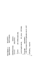
- FIG. 1 is a diagram showing an example of CORESET and search space setting mapping.
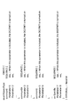
- FIG. 2 is a diagram showing an example of definition of existing search space settings.
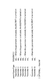
- FIG. 3 is a diagram showing an example of a search space setting definition according to the first embodiment.
- FIG. 4 is a diagram showing an example of a search space setting definition according to the second embodiment.
- FIG. 5 is a diagram showing an example of a search space setting definition according to a modification of the second embodiment.
- FIG. 6 is a diagram showing an example of a schematic configuration of a wireless communication system according to an embodiment.
- FIG. 7 is a diagram showing an example of the entire configuration of the radio base station according to an embodiment.
- FIG. 8 is a diagram illustrating an example of a functional configuration of a wireless base station according to an embodiment.
- FIG. 1 is a diagram showing an example of CORESET and search space setting mapping.
- FIG. 2 is a diagram showing an example of definition of existing search space settings.
- FIG. 3 is a diagram showing
- FIG. 9 is a diagram showing an example of the entire configuration of a user terminal according to an embodiment.
- FIG. 10 is a diagram showing an example of a functional configuration of a user terminal according to an embodiment.
- FIG. 11 is a diagram illustrating an example of a hardware configuration of a wireless base station and a user terminal according to an embodiment.
- a physical layer control signal for example, downlink control information (DCI: Downlink Control Information)
- DCI Downlink Control Information
- a base station for example, BS (Base Station), transmission / reception point (TRP: Transmission / Reception Point), eNB (eNodeB)
- CORESET COntrol REsource SET
- gNB NR Node B
- the CORESET is an allocation candidate area of a control channel (for example, PDCCH (Physical Downlink Control Channel)).
- the UE may receive CORESET configuration information (which may be referred to as a CORESET configuration) from the base station.
- the UE can detect the physical layer control signal by monitoring the CORESET set in the UE.
- the CORESET configuration may be notified, for example, by higher layer signaling.
- upper layer signaling may be, for example, any of Radio Resource Control (RRC) signaling, Medium Access Control (MAC) signaling, broadcast information, and the like, or a combination thereof.
- RRC Radio Resource Control
- MAC Medium Access Control
- the MAC signaling may use, for example, a MAC control element (MAC CE (Control Element)), a MAC PDU (Protocol Data Unit), or the like.
- the broadcast information may be, for example, a master information block (MIB), a system information block (SIB), a minimum system information (RMSI), and the like.
- the CORESET configuration mainly includes information on PDCCH resource association settings and RS association settings, and may include, for example, information on at least one of the following: ⁇ CORESET identifier (CORESET ID (Identifier)), -Scramble ID of demodulation reference signal (DMRS) for PDCCH, Time duration (e.g. 1, 2 or 3 symbols), Frequency-domain Resource Allocation, Mapping between control channel elements (CCEs) and resource element groups (REGs: interleaving, non-interleaving), ⁇ REG bundle size, ⁇ Index of shift amount in case of interleaving, Transmission configuration indication (TCI) status for PDCCH, • Enable / disable TCI fields.
- CORESET ID Identifier
- DMRS demodulation reference signal
- Time duration e.g. 1, 2 or 3 symbols
- Frequency-domain Resource Allocation e.g. 1, 2 or 3 symbols
- CCEs control channel elements
- REGs resource element groups
- TCI Transmission configuration indication
- a search region and search method for PDCCH candidates are defined as a search space (SS).
- the UE may receive search space configuration information (which may be referred to as a search space configuration) from the base station.
- the search space configuration may be notified, for example, by higher layer signaling (such as RRC signaling).
- the search space configuration mainly includes information on PDCCH monitoring related settings and decoding related settings, and may include, for example, information on at least one of the following: Search space identifier (search space ID), ⁇ CORESET ID to which the search space setting concerned is related, A flag indicating whether the common search space (C-SS: Common SS) or the UE specific search space (UE-SS: UE-specific SS), The number of PDCCH candidates for each aggregation level, ⁇ Monitoring cycle, ⁇ Monitoring offset, Monitoring pattern in the slot (eg 14 bit bitmap).
- the UE monitors CORESET based on the search space configuration.
- “monitor of CORESET” in the description of the present disclosure may be read as “monitor of search space (PDCCH candidate) associated with CORESET”, “monitor of downlink control channel (for example, PDCCH)” or the like.
- the UE can determine the correspondence between CORESET and the search space based on the CORESET ID included in the search space configuration.
- One CORESET may be associated with one or more search spaces.
- FIG. 1 is a diagram showing an example of CORESET and search space setting mapping.
- CORESET # 0 corresponds to search space setting # 0
- CORESET # 1 corresponds to search space settings # 1 and # 2
- CORESET # 2 corresponds to search space settings # 3 and # 4. .
- the case in which a plurality of search space settings are associated with one CORESET corresponds to, for example, the case in which both C-SS and UE-SS are set in the CORESET.
- one search space setting may be associated with a plurality of CORESETs.
- search spaces are considered: Type 0-PDCCH C-SS, Type 0 A-PDCCH C-SS, Type 1-PDCCH C-SS, Type 2-PDCCH C-SS, Type 3-PDCCH C-SS, UE-SS.
- Type 0-PDCCH C-SS is an SS for DCI format that is cyclic redundancy check (CRC) masking (scrambled) by System Information Radio Network Temporary Identifier (SI-RNTI) It may be called.
- CRC cyclic redundancy check
- SI-RNTI System Information Radio Network Temporary Identifier
- Type 0 A-PDCCH C-SS may be called SS for DCI format that is CRC scrambled by SI-RNTI.
- the type 0-PDCCH may be used, for example, for notification of RMSI, and the type 0A-PDCCH may be used, for example, for notification of another SI (OSI: Other SI).
- OSI Other SI
- Type 1-PDCCH C-SS is CRC scrambled by random access RNTI (RA-RNTI: Random Access RNTI), temporary cell RNTI (TC-RNTI: Temporary Cell RNTI) or cell RNTI (C-RNTI: Cell RNTI) May be called SS for the DCI format.
- RA-RNTI Random Access RNTI
- TC-RNTI Temporary Cell RNTI
- C-RNTI Cell RNTI
- Type 2-PDCCH C-SS may be called SS for DCI format that is CRC scrambled by P-RNTI (P-RNTI).
- Type 3-PDCCH C-SS INT-RNTI (INTerruption RNTI) for DL preemption indication, SFI-RNTI (Slot Format Indicator RNTI) for slot format indication, transmission power control (TPC for Physical Uplink Shared Channel) PUSCH (Physical Uplink Shared Channel) TPC-PUSCH-RNTI for Transmit Power Control, TPC-PUCCH-RNTI for TPC for PUCCH (Physical Uplink Control Channel), TPC-SRS-RNTI for TPC for CRS (Sounding Reference Signal), C-RNTI or It may also be called SS for DCI format CRC scrambled by CS-RNTI (Configured Scheduling RNTI).
- TPC-PUCCH-RNTI for TPC for PUCCH (Physical Uplink Control Channel)
- TPC-SRS-RNTI for TPC for CRS (Sounding Reference Signal)
- C-RNTI or It may also be called SS for DCI format CRC scrambled by CS-RNTI
- UE-SS may also be called SS for DCI format that is CRC scrambled by C-RNTI or CS-RNTI.
- the type of search space can also be said to be information that associates the search space with the DCI features (format, RNTI, etc.) transmitted in the monitored PDCCH candidate.
- C-SS Various types of C-SS, UE-SS, etc. may be defined.
- the UE can only recognize that the monitored PDCCH candidate corresponds to the C-SS or the UE-SS.
- FIG. 2 is a diagram showing an example of definition of existing search space settings.
- FIG. 2 shows ASN. 1 (Abstract Syntax Notation One) is described by the notation. The same applies to FIGS. 3, 4 and 5 described later.
- the search space information element (Search Space IE (Information Element)) of FIG. 2 corresponds to the above-described search space setting.
- the search space IE includes a parameter (searchSpaceType) indicating whether the search space is C-SS or UE-SS, as well as other information such as search space ID.
- the inventors have conceived of a method of setting SS that is suitably associated with CORESET.
- the search space configuration includes information (which may be called search space type information) to which type the search space corresponds.
- the UE can identify the type of search space to which the configured search space IE corresponds based on the information.
- FIG. 3 is a diagram showing an example of definition of search space type information according to the first embodiment.
- the search space IE is configured to include search space type information that specifically identifies one of the search spaces.
- searchSpaceType indicates, for example, a sequence “common0” indicating type 0-PDCCH C-SS, a sequence “common0A” indicating type 0A-PDCCH C-SS, and type 1-PDCCH C-SS
- searchSpaceType indicates, for example, a sequence “common0” indicating type 0-PDCCH C-SS, a sequence “common0A” indicating type 0A-PDCCH C-SS, and type 1-PDCCH C-SS
- the sequence “common1”, the sequence “common2” indicating type 2-PDCCH C-SS, the sequence “common3” indicating type 3-PDCCH C-SS, the sequence “ue-Specific” indicating UE-SS, etc. are defined .
- sequence here is ASN. It is one of the fields representing the type of one object, and may be called a sequence type.
- sequence “common0” may indicate that the value of “common0” is of the order sequence type and is composed of, for example, a plurality of value fields.
- search space IE including information of “common 0”
- search space corresponds to the type 0-PDCCH C-SS.
- sequence indicating the type may include a parameter (which may be called a DCI format specification parameter) specifying one or more DCI formats to be detected for the type.
- RNTI specification parameter specifying one or more RNTIs to be detected (may be called RNTI corresponding to the DCI format to be monitored) for the type. May be included.
- Parameters 1, 3, 5 and 7 are examples of DCI format specification parameters and / or RNTI specification parameters.
- search space type information includes “common3” and the DCI format specification parameter included in “common3” indicates, for example, “DCI format 2_0”, the UE configured with the IE has type 3-PDCCH C-SS. It may be determined that the DCI format 2_0 should be monitored.
- search space type information includes “common3” and the DCI format specification parameter included in “common3” indicates, for example, “DCI format 2_0, DCI format 2_1”, the UE configured with the relevant IE is of type 3- It may be determined to monitor DCI formats 2_0 and 2_1 in PDCCH C-SS.
- search space type information includes “common3” and the RNTI designation parameter included in “common3” indicates, for example, “INT-RNTI”, the UE configured with that IE has type 3-PDCCH C-SS. It may be determined to monitor the PDCCH scrambled by the INT-RNTI.
- the UE configured with the IE has type 3-PDCCH. It may be determined to monitor the PDCCH scrambled by INT-RNTI or SFI-RNTI in C-SS.
- the DCI format specification parameter and the RNTI specification parameter may be configured to be included when the search space type information has a specific value (for example, "common 3" or "ue-specific").
- the DCI format specification parameter or the RNTI specification parameter may be called a DCI format detection trigger parameter, an RNTI detection trigger parameter, or the like because the presence of the DCI format specification parameter or the RNTI specification parameter triggers the detection of the DCI format or RNTI of the subject.
- the UE can appropriately grasp the search space type corresponding to the search space configuration (IE), and can specify the DCI format detected using the search space type.
- IE search space configuration
- the second embodiment corresponds to the case where C-SS and U-SS are defined as search spaces and the type is not defined in each SS.
- FIG. 4 is a diagram showing an example of definition of search space type information according to the second embodiment.
- the search space IE is configured to include a sequence ("common” or "ue-specific") that specifically identifies one of the search spaces (C-SS or UE-SS).
- the sequence corresponds to search space type information.
- the UE When the UE is notified of, for example, a search space IE including “common” information, it can determine that the search space corresponds to the C-SS.
- the sequence for specifying the search space may include a parameter (which may be called a DCI format specification parameter) for specifying one or more DCI formats to be detected with respect to the search space.
- the sequence specifying the search space may include a parameter (which may be called an RNTI specification parameter) specifying one or more RNTIs to be detected for the type.
- Parameters 1, 3, 5 and 7 are examples of DCI format specification parameters and / or RNTI specification parameters.
- search space type information includes "common” and the DCI format specification parameter included in "common” indicates, for example, "DCI format 2_0", the UE configured with the IE can perform DCI format 2_0 in C-SS. It may be determined to monitor the
- the UE configured with the IE is a C-SS. It may be determined that the DCI formats 2_0 and 2_1 should be monitored.
- the UE configured with the IE is notified by C-SS by the INT-RNTI. It may be determined to monitor the scrambled PDCCH.
- search space type information includes "common” and the RNTI designation parameter included in "common” indicates, for example, "INT-RNTI, SFI-RNTI", the UE configured with the IE is in C-SS. It may be determined to monitor the PDCCH scrambled by INT-RNTI or SFI-RNTI.
- the search space type information includes "common” and the RNTI designation parameter included in "common” indicates, for example, "SI-RNTI, RA-RNTI, SFI-RNTI, C-RNTI", the IE is selected.
- the configured UE may be equivalent to being configured to monitor the type 0, type 0 A, type 1 and type 3-PDCCH C-SS described above.
- a plurality of search space type information when setting a plurality of types of monitors, a plurality of search space type information will be set. For example, a UE configured with a search space IE including “common0”, a search space IE including “common0A”, a search space IE including “common1”, and a search space IE including “common3” has type 0, type 0 A, It will be set to monitor Type 1 and Type 3-PDCCH C-SS.
- the UE can preferably specify the DCI format to be detected in the search space to which the search space configuration (IE) corresponds.
- IE search space configuration
- the search space IE includes a sequence ("common” or "ue-specific") that identifies the C-SS or UE-SS, but without the distinction in search space type information. It is also good.
- FIG. 5 is a diagram showing an example of definition of search space type information according to a modification of the second embodiment.
- the search space type information is configured by a sequence of parameters related to one or more search spaces.
- the parameters 1-6 are parameters for monitoring the search space corresponding to the conventional C-SS
- the parameters 7 and 8 correspond to the search space corresponding to the conventional UE-SS. It is a parameter to monitor.
- the search space type information may explicitly include a parameter indicating that the search space corresponds to any one or more of the C-SS, UE-SS and SS types.
- the UE operates in a stand-alone (SA: Stand-Alone) that operates independently without cooperating with an existing Radio Access Technology (RAT) (for example, LTE) or a non-standby operated in conjunction with an existing RAT. Operates based on Alone (NSA: Non-Stand-Alone).
- SA Stand-Alone
- RAT Radio Access Technology
- NSA Non-Stand-Alone
- the UE monitors the search space corresponding to the above-mentioned type 1-PDCCH C-SS and / or receives the setting for monitoring the search space regardless of which of the SA operation and the NSA operation. And may be assumed. In this case, the UE can reliably perform a random access procedure using, for example, a random access RNTI, and can establish communication with the network.
- search space corresponding to type 1-PDCCH C-SS may mean a search space for detecting a DCI format that is CRC-scrambled by RA-RNTI.
- the UE monitors the search space corresponding to the above-mentioned UE-SS and / or receives the setting for monitoring the search space regardless of which of the SA operation and the NSA operation. It may be assumed. In this case, the UE can reliably perform the UE-specific communication with, for example, the base station.
- the UE may be configured to at least always determine (be sure to monitor) a predetermined search space type based on one or more search space settings. For example, the UE is configured to at least necessarily determine (monitor) at least two types, Type 1-PDCCH C-SS and UE-SS, based on one or more search space configurations. It is also good.
- wireless communication system Wireless communication system
- communication is performed using any one or a combination of the wireless communication methods according to the above embodiments of the present disclosure.
- FIG. 6 is a diagram showing an example of a schematic configuration of a wireless communication system according to an embodiment.
- the radio communication system 1 applies carrier aggregation (CA) and / or dual connectivity (DC) in which a plurality of basic frequency blocks (component carriers) each having a system bandwidth (for example, 20 MHz) of the LTE system as one unit are integrated. can do.
- CA carrier aggregation
- DC dual connectivity
- the wireless communication system 1 includes LTE (Long Term Evolution), LTE-A (LTE-Advanced), LTE-B (LTE-Beyond), SUPER 3G, IMT-Advanced, 4G (4th generation mobile communication system), and 5G. It may be called (5th generation mobile communication system), NR (New Radio), FRA (Future Radio Access), New-RAT (Radio Access Technology) or the like, or may be called a system for realizing these.
- the radio communication system 1 includes a radio base station 11 forming a macrocell C1 with a relatively wide coverage, and radio base stations 12 (12a to 12c) disposed in the macrocell C1 and forming a small cell C2 narrower than the macrocell C1. And. Moreover, the user terminal 20 is arrange
- the user terminal 20 can be connected to both the radio base station 11 and the radio base station 12. It is assumed that the user terminal 20 simultaneously uses the macro cell C1 and the small cell C2 using CA or DC. Also, the user terminal 20 may apply CA or DC using a plurality of cells (CCs).
- CCs a plurality of cells
- Communication can be performed between the user terminal 20 and the radio base station 11 using a relatively low frequency band (for example, 2 GHz) and a narrow bandwidth carrier (also called an existing carrier, legacy carrier, etc.).
- a carrier having a wide bandwidth in a relatively high frequency band for example, 3.5 GHz, 5 GHz, etc.
- the configuration of the frequency band used by each wireless base station is not limited to this.
- the user terminal 20 can perform communication in each cell using time division duplex (TDD) and / or frequency division duplex (FDD). Also, in each cell (carrier), a single numerology may be applied, or a plurality of different numerologies may be applied.
- TDD time division duplex
- FDD frequency division duplex
- Numerology may be communication parameters applied to transmission and / or reception of a certain signal and / or channel, for example, subcarrier spacing, bandwidth, symbol length, cyclic prefix length, subframe length It may indicate at least one of TTI length, number of symbols per TTI, radio frame configuration, specific filtering processing performed by the transceiver in the frequency domain, and specific windowing processing performed by the transceiver in the time domain. For example, in the case where subcarrier intervals of constituent OFDM symbols are different and / or the number of OFDM symbols is different for a certain physical channel, the neurology may be referred to as different.
- the wireless base station 11 and the wireless base station 12 are connected by wire (for example, an optical fiber conforming to CPRI (Common Public Radio Interface), X2 interface, etc.) or wirelessly It may be done.
- wire for example, an optical fiber conforming to CPRI (Common Public Radio Interface), X2 interface, etc.
- CPRI Common Public Radio Interface
- X2 interface etc.
- the radio base station 11 and each radio base station 12 are connected to the higher station apparatus 30 and connected to the core network 40 via the higher station apparatus 30.
- the upper station apparatus 30 includes, for example, an access gateway apparatus, a radio network controller (RNC), a mobility management entity (MME), and the like, but is not limited thereto. Further, each wireless base station 12 may be connected to the higher station apparatus 30 via the wireless base station 11.
- RNC radio network controller
- MME mobility management entity
- the radio base station 11 is a radio base station having a relatively wide coverage, and may be called a macro base station, an aggregation node, an eNB (eNodeB), a transmission / reception point, or the like.
- the radio base station 12 is a radio base station having local coverage, and is a small base station, a micro base station, a pico base station, a femto base station, a HeNB (Home eNodeB), an RRH (Remote Radio Head), transmission and reception It may be called a point or the like.
- the radio base stations 11 and 12 are not distinguished, they are collectively referred to as the radio base station 10.
- Each user terminal 20 is a terminal compatible with various communication schemes such as LTE and LTE-A, and may include not only mobile communication terminals (mobile stations) but also fixed communication terminals (fixed stations).
- orthogonal frequency division multiple access (OFDMA) is applied to the downlink as a radio access scheme, and single carrier frequency division multiple access (SC-FDMA: single carrier) to the uplink.
- SC-FDMA single carrier frequency division multiple access
- Frequency Division Multiple Access and / or OFDMA is applied.
- OFDMA is a multicarrier transmission scheme in which a frequency band is divided into a plurality of narrow frequency bands (subcarriers) and data is mapped to each subcarrier to perform communication.
- SC-FDMA is a single carrier transmission that reduces interference between terminals by dividing the system bandwidth into a band configured by one or continuous resource blocks for each terminal, and a plurality of terminals use different bands. It is a system.
- the uplink and downlink radio access schemes are not limited to these combinations, and other radio access schemes may be used.
- a downlink shared channel (PDSCH: Physical Downlink Shared Channel) shared by each user terminal 20, a broadcast channel (PBCH: Physical Broadcast Channel), a downlink L1 / L2 control channel, etc. are used as downlink channels. Used. User data, upper layer control information, SIB (System Information Block), etc. are transmitted by the PDSCH. Also, a MIB (Master Information Block) is transmitted by the PBCH.
- PDSCH Physical Downlink Shared Channel
- PBCH Physical Broadcast Channel
- SIB System Information Block
- MIB Master Information Block
- the downlink L1 / L2 control channel includes PDCCH (Physical Downlink Control Channel), EPDCCH (Enhanced Physical Downlink Control Channel), PCFICH (Physical Control Format Indicator Channel), PHICH (Physical Hybrid-ARQ Indicator Channel) and the like.
- Downlink control information (DCI) including scheduling information of PDSCH and / or PUSCH is transmitted by PDCCH.
- scheduling information may be notified by DCI.
- DCI scheduling DL data reception may be referred to as DL assignment
- DCI scheduling UL data transmission may be referred to as UL grant.
- the number of OFDM symbols used for PDCCH is transmitted by PCFICH.
- Delivery confirmation information (for example, also referred to as retransmission control information, HARQ-ACK, and ACK / NACK) of HARQ (Hybrid Automatic Repeat reQuest) for the PUSCH is transmitted by the PHICH.
- the EPDCCH is frequency division multiplexed with a PDSCH (downlink shared data channel), and is used for transmission such as DCI, similarly to the PDCCH.
- an uplink shared channel (PUSCH: Physical Uplink Shared Channel) shared by each user terminal 20, an uplink control channel (PUCCH: Physical Uplink Control Channel), a random access channel (PRACH: Physical Random Access Channel) or the like is used.
- User data, upper layer control information, etc. are transmitted by PUSCH.
- downlink radio quality information (CQI: Channel Quality Indicator), delivery confirmation information, scheduling request (SR: Scheduling Request) and the like are transmitted by the PUCCH.
- the PRACH transmits a random access preamble for establishing a connection with a cell.
- a cell-specific reference signal (CRS: Cell-specific Reference Signal), a channel state information reference signal (CSI-RS: Channel State Information-Reference Signal), a demodulation reference signal (DMRS: DeModulation Reference Signal, positioning reference signal (PRS), etc.
- CRS Cell-specific Reference Signal
- CSI-RS Channel State Information-Reference Signal
- DMRS DeModulation Reference Signal
- PRS positioning reference signal
- SRS Sounding Reference Signal
- DMRS demodulation reference signal
- PRS positioning reference signal
- DMRS Demodulation reference signal
- PRS positioning reference signal
- FIG. 7 is a diagram showing an example of the entire configuration of the radio base station according to an embodiment.
- the radio base station 10 includes a plurality of transmitting and receiving antennas 101, an amplifier unit 102, a transmitting and receiving unit 103, a baseband signal processing unit 104, a call processing unit 105, and a transmission path interface 106. Note that each of the transmitting and receiving antenna 101, the amplifier unit 102, and the transmitting and receiving unit 103 may be configured to include one or more.
- User data transmitted from the radio base station 10 to the user terminal 20 by downlink is input from the higher station apparatus 30 to the baseband signal processing unit 104 via the transmission path interface 106.
- the baseband signal processing unit 104 performs packet data convergence protocol (PDCP) layer processing, user data division / combination, RLC layer transmission processing such as RLC (Radio Link Control) retransmission control, and MAC (Medium Access) for user data.
- Control Transmission processing such as retransmission control (for example, HARQ transmission processing), scheduling, transmission format selection, channel coding, inverse fast Fourier transform (IFFT) processing, precoding processing, etc. It is transferred to 103. Further, transmission processing such as channel coding and inverse fast Fourier transform is also performed on the downlink control signal and transferred to the transmission / reception unit 103.
- the transmission / reception unit 103 converts the baseband signal output from the baseband signal processing unit 104 for each antenna into a radio frequency band and transmits the baseband signal.
- the radio frequency signal frequency-converted by the transmitting and receiving unit 103 is amplified by the amplifier unit 102 and transmitted from the transmitting and receiving antenna 101.
- the transmission / reception unit 103 can be configured of a transmitter / receiver, a transmission / reception circuit, or a transmission / reception device described based on the common recognition in the technical field according to the present disclosure.
- the transmitting and receiving unit 103 may be configured as an integrated transmitting and receiving unit, or may be configured from a transmitting unit and a receiving unit.
- the radio frequency signal received by the transmission / reception antenna 101 is amplified by the amplifier unit 102.
- the transmitting and receiving unit 103 receives the upstream signal amplified by the amplifier unit 102.
- the transmission / reception unit 103 frequency-converts the received signal into a baseband signal and outputs the result to the baseband signal processing unit 104.
- the baseband signal processing unit 104 performs Fast Fourier Transform (FFT) processing, Inverse Discrete Fourier Transform (IDFT) processing, and error correction on user data included in the input upstream signal. Decoding, reception processing of MAC retransmission control, and reception processing of RLC layer and PDCP layer are performed, and are transferred to the higher station apparatus 30 via the transmission path interface 106.
- the call processing unit 105 performs call processing (setting, release, etc.) of the communication channel, state management of the radio base station 10, management of radio resources, and the like.
- the transmission path interface 106 transmits and receives signals to and from the higher station apparatus 30 via a predetermined interface. Also, the transmission path interface 106 transmits / receives signals (backhaul signaling) to / from the other wireless base station 10 via an inter-base station interface (for example, an optical fiber conforming to CPRI (Common Public Radio Interface), X2 interface). May be
- an inter-base station interface for example, an optical fiber conforming to CPRI (Common Public Radio Interface), X2 interface.
- the transmission / reception unit 103 may transmit downlink control information (for example, DCI) using a control resource set (CORESET: COntrol REsource SET) associated with a specific search space.
- DCI downlink control information
- CORESET COntrol REsource SET
- the transmitting and receiving unit 103 may transmit CORESET setting, search space setting and the like to the user terminal 20.
- FIG. 8 is a diagram illustrating an example of a functional configuration of a wireless base station according to an embodiment of the present disclosure.
- the functional block of the characteristic part in this embodiment is mainly shown, and it may be assumed that the wireless base station 10 also has another functional block required for wireless communication.
- the baseband signal processing unit 104 at least includes a control unit (scheduler) 301, a transmission signal generation unit 302, a mapping unit 303, a reception signal processing unit 304, and a measurement unit 305. Note that these configurations may be included in the wireless base station 10, and some or all of the configurations may not be included in the baseband signal processing unit 104.
- a control unit (scheduler) 301 performs control of the entire radio base station 10.
- the control unit 301 can be configured of a controller, a control circuit, or a control device described based on the common recognition in the technical field according to the present disclosure.
- the control unit 301 controls, for example, generation of a signal in the transmission signal generation unit 302, assignment of a signal in the mapping unit 303, and the like. Further, the control unit 301 controls reception processing of a signal in the reception signal processing unit 304, measurement of a signal in the measurement unit 305, and the like.
- the control unit 301 schedules (for example, resources) system information, downlink data signals (for example, signals transmitted on PDSCH), downlink control signals (for example, signals transmitted on PDCCH and / or EPDCCH, delivery confirmation information, etc.) Control allocation). Further, the control unit 301 controls generation of the downlink control signal, the downlink data signal, and the like based on the result of determining whether the retransmission control for the uplink data signal is necessary or not.
- the control unit 301 controls scheduling of synchronization signals (for example, PSS (Primary Synchronization Signal) / SSS (Secondary Synchronization Signal), downlink reference signals (for example, CRS, CSI-RS, DMRS) and the like.
- synchronization signals for example, PSS (Primary Synchronization Signal) / SSS (Secondary Synchronization Signal)
- SSS Secondary Synchronization Signal
- CRS Channel Reference Signal
- CSI-RS CSI-RS
- DMRS Downlink reference signals
- the control unit 301 may use an uplink data signal (for example, a signal transmitted on PUSCH), an uplink control signal (for example, a signal transmitted on PUCCH and / or PUSCH, delivery confirmation information, etc.), a random access preamble (for example, PRACH). Control the scheduling of transmitted signals, uplink reference signals, etc.
- an uplink data signal for example, a signal transmitted on PUSCH
- an uplink control signal for example, a signal transmitted on PUCCH and / or PUSCH, delivery confirmation information, etc.
- a random access preamble for example, PRACH
- the control unit 301 may perform control to transmit DCI using CORESET.
- the control unit 301 may control to generate and transmit DCI in a specific search space using a specific DCI format and an RNTI corresponding to the format.
- the transmission signal generation unit 302 generates a downlink signal (a downlink control signal, a downlink data signal, a downlink reference signal, and the like) based on an instruction from the control unit 301, and outputs the downlink signal to the mapping unit 303.
- the transmission signal generation unit 302 can be configured from a signal generator, a signal generation circuit, or a signal generation device described based on the common recognition in the technical field according to the present disclosure.
- the transmission signal generation unit 302 generates, for example, DL assignment for notifying downlink data allocation information and / or UL grant for notifying uplink data allocation information, based on an instruction from the control unit 301.
- DL assignment and UL grant are both DCI and follow DCI format.
- coding processing and modulation processing are performed on the downlink data signal according to a coding rate, a modulation method, and the like determined based on channel state information (CSI: Channel State Information) and the like from each user terminal 20.
- CSI Channel State Information
- Mapping section 303 maps the downlink signal generated by transmission signal generation section 302 to a predetermined radio resource based on an instruction from control section 301, and outputs the mapped downlink signal to transmission / reception section 103.
- the mapping unit 303 can be configured from a mapper, a mapping circuit or a mapping device described based on the common recognition in the technical field according to the present disclosure.
- the reception signal processing unit 304 performs reception processing (for example, demapping, demodulation, decoding, and the like) on the reception signal input from the transmission / reception unit 103.
- the reception signal is, for example, an uplink signal (uplink control signal, uplink data signal, uplink reference signal, etc.) transmitted from the user terminal 20.
- the received signal processing unit 304 can be configured from a signal processor, a signal processing circuit or a signal processing device described based on the common recognition in the technical field according to the present disclosure.
- the reception signal processing unit 304 outputs the information decoded by the reception process to the control unit 301. For example, when the PUCCH including the HARQ-ACK is received, the HARQ-ACK is output to the control unit 301. Further, the reception signal processing unit 304 outputs the reception signal and / or the signal after reception processing to the measurement unit 305.
- the measurement unit 305 performs measurement on the received signal.
- the measuring unit 305 can be configured from a measuring device, a measuring circuit, or a measuring device described based on the common recognition in the technical field according to the present disclosure.
- the measurement unit 305 may perform Radio Resource Management (RRM) measurement, Channel State Information (CSI) measurement, and the like based on the received signal.
- the measurement unit 305 may use received power (for example, reference signal received power (RSRP)), received quality (for example, reference signal received quality (RSRQ), signal to interference plus noise ratio (SINR), signal to noise ratio (SNR)). , Signal strength (e.g., received signal strength indicator (RSSI)), channel information (e.g., CSI), and the like.
- RSRP reference signal received power
- RSSI received signal strength indicator
- CSI channel information
- the measurement result may be output to the control unit 301.
- FIG. 9 is a diagram showing an example of the entire configuration of a user terminal according to an embodiment.
- the user terminal 20 includes a plurality of transmitting and receiving antennas 201, an amplifier unit 202, a transmitting and receiving unit 203, a baseband signal processing unit 204, and an application unit 205.
- each of the transmitting and receiving antenna 201, the amplifier unit 202, and the transmitting and receiving unit 203 may be configured to include one or more.
- the radio frequency signal received by the transmission / reception antenna 201 is amplified by the amplifier unit 202.
- the transmitting and receiving unit 203 receives the downlink signal amplified by the amplifier unit 202.
- the transmission / reception unit 203 frequency-converts the received signal into a baseband signal and outputs the result to the baseband signal processing unit 204.
- the transmission / reception unit 203 can be configured of a transmitter / receiver, a transmission / reception circuit, or a transmission / reception device described based on the common recognition in the technical field according to the present disclosure.
- the transmission / reception unit 203 may be configured as an integrated transmission / reception unit, or may be configured from a transmission unit and a reception unit.
- the baseband signal processing unit 204 performs reception processing of FFT processing, error correction decoding, retransmission control, and the like on the input baseband signal.
- the downlink user data is transferred to the application unit 205.
- the application unit 205 performs processing on a layer higher than the physical layer and the MAC layer. Moreover, broadcast information may also be transferred to the application unit 205 among downlink data.
- uplink user data is input from the application unit 205 to the baseband signal processing unit 204.
- the baseband signal processing unit 204 performs transmission processing of retransmission control (for example, transmission processing of HARQ), channel coding, precoding, discrete Fourier transform (DFT) processing, IFFT processing, etc. It is transferred to 203.
- the transmission / reception unit 203 converts the baseband signal output from the baseband signal processing unit 204 into a radio frequency band and transmits it.
- the radio frequency signal frequency-converted by the transmitting and receiving unit 203 is amplified by the amplifier unit 202 and transmitted from the transmitting and receiving antenna 201.
- the transmission / reception unit 203 may monitor the control resource set (CORESET: COntrol REsource SET) using a specific search space determined by the control unit 401 described later.
- CORESET COntrol REsource SET
- the transmission / reception unit 203 may receive CORESET setting, search space setting, and the like from the radio base station 10.
- FIG. 10 is a diagram showing an example of a functional configuration of a user terminal according to an embodiment.
- the functional block of the characteristic part in this embodiment is mainly shown, and it may be assumed that the user terminal 20 also has another functional block required for wireless communication.
- the baseband signal processing unit 204 included in the user terminal 20 at least includes a control unit 401, a transmission signal generation unit 402, a mapping unit 403, a reception signal processing unit 404, and a measurement unit 405. Note that these configurations may be included in the user terminal 20, and some or all of the configurations may not be included in the baseband signal processing unit 204.
- the control unit 401 controls the entire user terminal 20.
- the control unit 401 can be configured of a controller, a control circuit, or a control device described based on the common recognition in the technical field according to the present disclosure.
- the control unit 401 controls, for example, generation of a signal in the transmission signal generation unit 402, assignment of a signal in the mapping unit 403, and the like. Further, the control unit 401 controls reception processing of signals in the reception signal processing unit 404, measurement of signals in the measurement unit 405, and the like.
- the control unit 401 acquires the downlink control signal and the downlink data signal transmitted from the radio base station 10 from the reception signal processing unit 404.
- the control unit 401 controls the generation of the uplink control signal and / or the uplink data signal based on the result of determining the necessity of the retransmission control for the downlink control signal and / or the downlink data signal.
- the control unit 401 may determine the type of a specific search space based on predetermined information (for example, may be referred to as search space type information) included in the search space setting.
- the predetermined information is information for specifying any one of a plurality of types of common search space (C-SS) (for example, type 0 / 0A / 1/2 / 3-PDCCH C-SS). May be included.
- C-SS common search space
- the information for identifying any one of the plurality of C-SS types may include a DCI format to be detected for the type and a parameter specifying at least one of the RNTI corresponding to the format.
- the control unit 401 may specify a DCI format detected using a specific search space based on the parameters.
- the predetermined information includes information indicating that the specific search space is C-SS (for example, information indicating C-SS but not designating multiple types of C-SS), and the information further includes A plurality of parameters specifying at least one of the DCI format to be detected for the C-SS and the RNTI corresponding to the format may be included.
- the control unit 401 may specify a DCI format detected using a specific search space based on the plurality of parameters included.
- a particular SS eg, C-SS
- another SS eg, U-SS or another SS
- the control unit 401 determines a type of search space for detecting a DCI format to be scrambled by CRC (Cyclic Redundancy Check) by random access RNTI (Radio Network Temporary Identifier) based on one or more search space settings, and a user It may be configured to determine at least two types: terminal specific search space (UE-SS) type.
- CRC Cyclic Redundancy Check
- RNTI Radio Network Temporary Identifier
- the type of UE-SS may indicate UE-SS.
- the UE-SS may not be configured to include more than one type.
- the search space type information may be information indicating C-SS or UE-SS.
- control unit 401 When the control unit 401 acquires various types of information notified from the radio base station 10 from the received signal processing unit 404, the control unit 401 may update parameters used for control based on the information.
- the transmission signal generation unit 402 generates an uplink signal (uplink control signal, uplink data signal, uplink reference signal or the like) based on an instruction from the control unit 401, and outputs the uplink signal to the mapping unit 403.
- the transmission signal generation unit 402 can be configured from a signal generator, a signal generation circuit or a signal generation device described based on the common recognition in the technical field according to the present disclosure.
- the transmission signal generation unit 402 generates, for example, an uplink control signal related to delivery confirmation information, channel state information (CSI), and the like based on an instruction from the control unit 401. Further, the transmission signal generation unit 402 generates an uplink data signal based on an instruction from the control unit 401. For example, when the downlink control signal notified from the radio base station 10 includes a UL grant, the transmission signal generation unit 402 is instructed by the control unit 401 to generate an uplink data signal.
- CSI channel state information
- Mapping section 403 maps the uplink signal generated by transmission signal generation section 402 to a radio resource based on an instruction from control section 401, and outputs the uplink signal to transmission / reception section 203.
- the mapping unit 403 can be configured from a mapper, a mapping circuit, or a mapping device described based on the common recognition in the technical field according to the present disclosure.
- the reception signal processing unit 404 performs reception processing (for example, demapping, demodulation, decoding, and the like) on the reception signal input from the transmission / reception unit 203.
- the reception signal is, for example, a downlink signal (a downlink control signal, a downlink data signal, a downlink reference signal, or the like) transmitted from the radio base station 10.
- the received signal processing unit 404 can be configured from a signal processor, a signal processing circuit or a signal processing device described based on the common recognition in the technical field according to the present disclosure. Further, the received signal processing unit 404 can configure a receiving unit according to the present disclosure.
- the reception signal processing unit 404 outputs the information decoded by the reception process to the control unit 401.
- the received signal processing unit 404 outputs, for example, broadcast information, system information, RRC signaling, DCI, and the like to the control unit 401. Further, the reception signal processing unit 404 outputs the reception signal and / or the signal after reception processing to the measurement unit 405.
- the measurement unit 405 performs measurement on the received signal.
- the measuring unit 405 can be configured from a measuring device, a measuring circuit, or a measuring device described based on the common recognition in the technical field according to the present disclosure.
- the measurement unit 405 may perform RRM measurement, CSI measurement, and the like based on the received signal.
- the measurement unit 405 may measure reception power (for example, RSRP), reception quality (for example, RSRQ, SINR, SNR), signal strength (for example, RSSI), channel information (for example, CSI), and the like.
- the measurement result may be output to the control unit 401.
- each functional block (components) are realized by any combination of hardware and / or software.
- the implementation method of each functional block is not particularly limited. That is, each functional block may be realized using one physically and / or logically coupled device, or directly and / or two or more physically and / or logically separated devices. Or it may connect indirectly (for example, using a wire communication and / or radio), and it may be realized using a plurality of these devices.
- a wireless base station, a user terminal, and the like in an embodiment of the present disclosure may function as a computer that performs the processing of the wireless communication method of the present disclosure.
- FIG. 11 is a diagram illustrating an example of a hardware configuration of a wireless base station and a user terminal according to an embodiment.
- the above-described wireless base station 10 and user terminal 20 may be physically configured as a computer device including a processor 1001, a memory 1002, a storage 1003, a communication device 1004, an input device 1005, an output device 1006, a bus 1007 and the like. Good.
- the term “device” can be read as a circuit, a device, a unit, or the like.
- the hardware configuration of the radio base station 10 and the user terminal 20 may be configured to include one or more of the devices illustrated in the figure, or may be configured without including some devices.
- processor 1001 may be implemented by one or more chips.
- Each function in the radio base station 10 and the user terminal 20 is calculated by causing the processor 1001 to read predetermined software (program) on hardware such as the processor 1001 and the memory 1002, and the communication device 1004 is performed. This is realized by controlling communication, and controlling reading and / or writing of data in the memory 1002 and the storage 1003.
- the processor 1001 operates, for example, an operating system to control the entire computer.
- the processor 1001 may be configured by a central processing unit (CPU) including an interface with a peripheral device, a control device, an arithmetic device, a register, and the like.
- CPU central processing unit
- the above-described baseband signal processing unit 104 (204), call processing unit 105, and the like may be realized by the processor 1001.
- the processor 1001 reads a program (program code), a software module, data, and the like from the storage 1003 and / or the communication device 1004 to the memory 1002, and executes various processing according to these.
- a program a program that causes a computer to execute at least a part of the operations described in the above-described embodiment is used.
- the control unit 401 of the user terminal 20 may be realized by a control program stored in the memory 1002 and operating in the processor 1001, or may be realized similarly for other functional blocks.
- the memory 1002 is a computer readable recording medium, and for example, at least at least a read only memory (ROM), an erasable programmable ROM (EPROM), an electrically EPROM (EEPROM), a random access memory (RAM), or any other suitable storage medium. It may be configured by one.
- the memory 1002 may be called a register, a cache, a main memory (main storage device) or the like.
- the memory 1002 may store a program (program code), a software module, and the like that can be executed to implement the wireless communication method according to an embodiment.
- the storage 1003 is a computer readable recording medium, and for example, a flexible disk, a floppy (registered trademark) disk, a magneto-optical disk (for example, a compact disk (CD-ROM (Compact Disc ROM), etc.), a digital versatile disk, Blu-ray® disc), removable disc, hard disc drive, smart card, flash memory device (eg card, stick, key drive), magnetic stripe, database, server, at least one other suitable storage medium May be configured by The storage 1003 may be called an auxiliary storage device.
- a computer readable recording medium for example, a flexible disk, a floppy (registered trademark) disk, a magneto-optical disk (for example, a compact disk (CD-ROM (Compact Disc ROM), etc.), a digital versatile disk, Blu-ray® disc), removable disc, hard disc drive, smart card, flash memory device (eg card, stick, key drive), magnetic stripe, database, server, at least one other suitable storage medium May be configured by
- the communication device 1004 is hardware (transmission / reception device) for performing communication between computers via a wired and / or wireless network, and is also called, for example, a network device, a network controller, a network card, a communication module, or the like.
- the communication device 1004 includes, for example, a high frequency switch, a duplexer, a filter, a frequency synthesizer, and the like to realize, for example, frequency division duplex (FDD) and / or time division duplex (TDD). It may be configured.
- FDD frequency division duplex
- TDD time division duplex
- the transmission / reception antenna 101 (201), the amplifier unit 102 (202), the transmission / reception unit 103 (203), the transmission path interface 106, and the like described above may be realized by the communication device 1004.
- the input device 1005 is an input device (for example, a keyboard, a mouse, a microphone, a switch, a button, a sensor, and the like) that receives an input from the outside.
- the output device 1006 is an output device (for example, a display, a speaker, a light emitting diode (LED) lamp, and the like) that performs output to the outside.
- the input device 1005 and the output device 1006 may be integrated (for example, a touch panel).
- each device such as the processor 1001 and the memory 1002 is connected by a bus 1007 for communicating information.
- the bus 1007 may be configured using a single bus, or may be configured using different buses between devices.
- radio base station 10 and the user terminal 20 may be microprocessors, digital signal processors (DSPs), application specific integrated circuits (ASICs), programmable logic devices (PLDs), field programmable gate arrays (FPGAs), etc.
- DSPs digital signal processors
- ASICs application specific integrated circuits
- PLDs programmable logic devices
- FPGAs field programmable gate arrays
- Hardware may be included, and part or all of each functional block may be realized using the hardware.
- processor 1001 may be implemented using at least one of these hardware.
- the channels and / or symbols may be signaling.
- the signal may be a message.
- the reference signal may be abbreviated as RS (Reference Signal), and may be referred to as a pilot (Pilot), a pilot signal or the like according to an applied standard.
- a component carrier CC: Component Carrier
- CC Component Carrier
- the radio frame may be configured by one or more periods (frames) in the time domain.
- Each of the one or more periods (frames) that constitute a radio frame may be referred to as a subframe.
- a subframe may be configured by one or more slots in the time domain.
- the subframes may be of a fixed time length (e.g., 1 ms) independent of the neurology.
- the slot may be configured by one or more symbols in the time domain (such as orthogonal frequency division multiplexing (OFDM) symbols, single carrier frequency division multiple access (SC-FDMA) symbols, etc.).
- the slot may be a time unit based on the neurology.
- the slot may include a plurality of minislots. Each minislot may be configured by one or more symbols in the time domain. Minislots may also be referred to as subslots.
- a radio frame, a subframe, a slot, a minislot and a symbol all represent time units when transmitting a signal.
- subframes, slots, minislots and symbols other names corresponding to each may be used.
- one subframe may be referred to as a transmission time interval (TTI)
- TTI transmission time interval
- a plurality of consecutive subframes may be referred to as a TTI
- one slot or one minislot may be referred to as a TTI.
- TTI transmission time interval
- the subframe and / or TTI may be a subframe (1 ms) in existing LTE, a period shorter than 1 ms (eg, 1-13 symbols), or a period longer than 1 ms. It may be.
- the unit representing TTI may be called a slot, a minislot, etc. instead of a subframe.
- TTI refers to, for example, the minimum time unit of scheduling in wireless communication.
- the radio base station performs scheduling to assign radio resources (frequency bandwidth usable in each user terminal, transmission power, etc.) to each user terminal in TTI units.
- radio resources frequency bandwidth usable in each user terminal, transmission power, etc.
- the TTI may be a transmission time unit of a channel encoded data packet (transport block), a code block, and / or a codeword, or may be a processing unit such as scheduling and link adaptation. Note that, when a TTI is given, the time interval (eg, the number of symbols) in which the transport block, the code block, and / or the codeword is actually mapped may be shorter than the TTI.
- one or more TTIs may be the minimum time unit of scheduling.
- the number of slots (the number of minislots) constituting the minimum time unit of the scheduling may be controlled.
- a TTI having a time length of 1 ms may be referred to as a normal TTI (TTI in LTE Rel. 8-12), a normal TTI, a long TTI, a normal subframe, a normal subframe, a long subframe, or the like.
- a TTI shorter than a normal TTI may be referred to as a shortened TTI, a short TTI, a partial TTI (partial or fractional TTI), a shortened subframe, a short subframe, a minislot, a subslot, or the like.
- a long TTI for example, a normal TTI, a subframe, etc.
- a short TTI eg, a shortened TTI, etc.
- a resource block is a resource allocation unit in time domain and frequency domain, and may include one or more consecutive subcarriers (subcarriers) in the frequency domain. Also, an RB may include one or more symbols in the time domain, and may be one slot, one minislot, one subframe, or one TTI in length. One TTI and one subframe may be respectively configured by one or more resource blocks. Note that one or more RBs may be a physical resource block (PRB: Physical RB), a subcarrier group (SCG: Sub-Carrier Group), a resource element group (REG: Resource Element Group), a PRB pair, an RB pair, etc. It may be called.
- PRB Physical resource block
- SCG Sub-Carrier Group
- REG Resource Element Group
- a resource block may be configured by one or more resource elements (RE: Resource Element).
- RE Resource Element
- one RE may be one subcarrier and one symbol radio resource region.
- the above-described structures such as the radio frame, subframe, slot, minislot and symbol are merely examples.
- the number of subframes included in a radio frame the number of slots per subframe or radio frame, the number of minislots included in a slot, the number of symbols and RBs included in a slot or minislot, included in an RB
- the number of subcarriers, as well as the number of symbols in a TTI, the symbol length, the cyclic prefix (CP) length, and other configurations can be variously changed.
- the information, parameters, etc. described in the present specification may be expressed using absolute values, may be expressed using relative values from predetermined values, or other corresponding information. May be represented.
- radio resources may be indicated by a predetermined index.
- the names used for parameters and the like in the present specification are not limited names in any respect.
- various channels PUCCH (Physical Uplink Control Channel), PDCCH (Physical Downlink Control Channel), etc.
- information elements can be identified by any suitable names, various assignments are made to these various channels and information elements.
- the name is not limited in any way.
- data, instructions, commands, information, signals, bits, symbols, chips etc may be voltage, current, electromagnetic waves, magnetic fields or particles, optical fields or photons, or any of these May be represented by a combination of
- information, signals, etc. may be output from the upper layer to the lower layer and / or from the lower layer to the upper layer.
- Information, signals, etc. may be input / output via a plurality of network nodes.
- the input / output information, signals and the like may be stored in a specific place (for example, a memory) or may be managed using a management table. Information, signals, etc. input and output can be overwritten, updated or added. The output information, signals and the like may be deleted. The input information, signals and the like may be transmitted to other devices.
- notification of information is not limited to the aspects / embodiments described herein, and may be performed using other methods.
- notification of information may be physical layer signaling (eg, downlink control information (DCI), uplink control information (UCI)), upper layer signaling (eg, RRC (Radio Resource Control) signaling, It may be implemented by broadcast information (Master Information Block (MIB), System Information Block (SIB), etc.), MAC (Medium Access Control) signaling, other signals, or a combination thereof.
- DCI downlink control information
- UCI uplink control information
- RRC Radio Resource Control
- MIB Master Information Block
- SIB System Information Block
- MAC Medium Access Control
- the physical layer signaling may be called L1 / L2 (Layer 1 / Layer 2) control information (L1 / L2 control signal), L1 control information (L1 control signal), or the like.
- RRC signaling may be referred to as an RRC message, and may be, for example, an RRC connection setup (RRC Connection Setup) message, an RRC connection reconfiguration (RRC Connection Reconfiguration) message, or the like.
- MAC signaling may be notified using, for example, a MAC control element (MAC CE (Control Element)).
- notification of predetermined information is not limited to explicit notification, but implicitly (for example, by not notifying the predetermined information or other information Notification may be performed).
- the determination may be performed by a value (0 or 1) represented by one bit, or may be performed by a boolean value represented by true or false. , Numerical comparison (for example, comparison with a predetermined value) may be performed.
- Software may be called software, firmware, middleware, microcode, hardware description language, or any other name, and may be instructions, instruction sets, codes, code segments, program codes, programs, subprograms, software modules. Should be interpreted broadly to mean applications, software applications, software packages, routines, subroutines, objects, executables, threads of execution, procedures, functions, etc.
- software, instructions, information, etc. may be sent and received via a transmission medium.
- software may use a wired technology (coaxial cable, fiber optic cable, twisted pair, digital subscriber line (DSL), etc.) and / or a wireless technology (infrared, microwave, etc.), a website, a server
- wired technology coaxial cable, fiber optic cable, twisted pair, digital subscriber line (DSL), etc.
- wireless technology infrared, microwave, etc.
- system and "network” as used herein are used interchangeably.
- base station Base Station
- radio base station eNB
- gNB gigad Generation
- cell cell
- cell group cell group
- carrier carrier
- carrier may be used interchangeably.
- a base station may also be called in terms of a fixed station (Node station), NodeB, eNodeB (eNB), access point (access point), transmission point, reception point, femtocell, small cell, and so on.
- a base station may accommodate one or more (e.g., three) cells (also called sectors). If the base station accommodates multiple cells, the entire coverage area of the base station can be partitioned into multiple smaller areas, each smaller area being a base station subsystem (eg, a small base station for indoor use (RRH: Communication service can also be provided by Remote Radio Head).
- RRH Communication service can also be provided by Remote Radio Head.
- the terms "cell” or “sector” refer to part or all of the coverage area of a base station and / or a base station subsystem serving communication services in this coverage.
- MS mobile station
- UE user equipment
- the mobile station may be a subscriber station, a mobile unit, a subscriber unit, a wireless unit, a remote unit, a mobile device, a wireless device, a wireless communication device, a remote device, a mobile subscriber station, an access terminal, a mobile terminal, a wireless terminal, by those skilled in the art. It may also be called a terminal, a remote terminal, a handset, a user agent, a mobile client, a client or some other suitable term.
- the radio base station in the present specification may be replaced with a user terminal.
- each aspect / embodiment of the present disclosure may be applied to a configuration in which communication between a wireless base station and a user terminal is replaced with communication between a plurality of user terminals (D2D: Device-to-Device).
- the user terminal 20 may have a function that the above-described radio base station 10 has.
- the wordings such as "up” and “down” may be read as "side".
- the upstream channel may be read as a side channel.
- a user terminal herein may be read at a radio base station.
- the radio base station 10 may have a function that the above-described user terminal 20 has.
- the operation supposed to be performed by the base station may be performed by its upper node in some cases.
- various operations performed for communication with a terminal may be a base station, one or more network nodes other than the base station (eg, It is apparent that this can be performed by MME (Mobility Management Entity), S-GW (Serving-Gateway), etc. but not limited thereto or a combination thereof.
- MME Mobility Management Entity
- S-GW Serving-Gateway
- Each aspect / embodiment described in the present specification includes LTE (Long Term Evolution), LTE-A (LTE-Advanced), LTE-B (LTE-Beyond), SUPER 3G, IMT-Advanced, 4G (4th generation mobile) Communication system), 5G (5th generation mobile communication system), FRA (Future Radio Access), New-RAT (Radio Access Technology), NR (New Radio), NX (New radio access), FX (Future generation radio access), GSM (registered trademark) (Global System for Mobile communications), CDMA2000, UMB (Ultra Mobile Broadband), IEEE 802.11 (Wi-Fi (registered trademark)), IEEE 802.16 (WiMAX (registered trademark)), IEEE 802 .20, UWB (Ultra-Wide Band), Bluetooth (registered trademark) And / or systems based on other suitable wireless communication methods and / or extended next generation systems based on these.
- LTE Long Term Evolution
- LTE-A Long Term Evolution-Advanced
- any reference to an element using the designation "first”, “second” and the like as used herein does not generally limit the quantity or order of those elements. These designations may be used herein as a convenient way of distinguishing between two or more elements. Thus, reference to the first and second elements does not mean that only two elements can be taken or that the first element must somehow precede the second element.
- determining may encompass a wide variety of operations. For example, “determination” may be calculating, computing, processing, deriving, investigating, looking up (eg, table, database or other data) A search on structure), ascertaining, etc. may be considered as “determining”. Also, “determination” may be receiving (e.g. receiving information), transmitting (e.g. transmitting information), input (input), output (output), access (access) It may be considered as “determining” (eg, accessing data in memory) and the like. Also, “determination” is considered to be “determination” to resolve, select, choose, choose, establish, compare, etc. It is also good. That is, “determination” may be considered as “determining” some action.
- connection refers to any direct or indirect connection between two or more elements or It means a bond and can include the presence of one or more intermediate elements between two elements “connected” or “connected” to each other.
- the coupling or connection between elements may be physical, logical or a combination thereof. For example, “connection” may be read as "access”.
- the radio frequency domain It can be considered as “connected” or “coupled” with one another using electromagnetic energy or the like having wavelengths in the microwave region and / or the light (both visible and invisible) regions.
- a and B are different may mean “A and B are different from each other”.
- the terms “leave”, “combined” and the like may be interpreted similarly.
Landscapes
- Engineering & Computer Science (AREA)
- Signal Processing (AREA)
- Computer Networks & Wireless Communication (AREA)
- Quality & Reliability (AREA)
- Mobile Radio Communication Systems (AREA)
- Radar Systems Or Details Thereof (AREA)
Abstract
Description
・CORESETの識別子(CORESET ID(Identifier))、
・PDCCH用の復調用参照信号(DMRS:DeModulation Reference Signal)のスクランブルID、
・時間長(time duration)(例えば、1、2又は3シンボル)、
・周波数領域のリソース割り当て(Frequency-domain Resource Allocation)、
・制御チャネル要素(CCE:Control Channel Element)とリソース要素グループ(REG:Resource Element Group)とのマッピング(インターリーブ、ノンインターリーブ)、
・REGバンドルサイズ、
・インターリーブの場合のシフト量のインデックス、
・PDCCH用の送信設定通知(TCI:Transmission Configuration Indication)状態、
・TCIフィールドの有効化/無効化。 The CORESET configuration mainly includes information on PDCCH resource association settings and RS association settings, and may include, for example, information on at least one of the following:
・ CORESET identifier (CORESET ID (Identifier)),
-Scramble ID of demodulation reference signal (DMRS) for PDCCH,
Time duration (e.g. 1, 2 or 3 symbols),
Frequency-domain Resource Allocation,
Mapping between control channel elements (CCEs) and resource element groups (REGs: interleaving, non-interleaving),
・ REG bundle size,
· Index of shift amount in case of interleaving,
Transmission configuration indication (TCI) status for PDCCH,
• Enable / disable TCI fields.
・サーチスペースの識別子(サーチスペースID)、
・当該サーチスペース設定が関連するCORESET ID、
・共通サーチスペース(C-SS:Common SS)かUE固有サーチスペース(UE-SS:UE-specific SS)かを示すフラグ、
・アグリゲーションレベルごとのPDCCH候補数、
・モニタリング周期、
・モニタリングオフセット、
・スロット内のモニタリングパターン(例えば14ビットのビットマップ)。 The search space configuration mainly includes information on PDCCH monitoring related settings and decoding related settings, and may include, for example, information on at least one of the following:
Search space identifier (search space ID),
・ CORESET ID to which the search space setting concerned is related,
A flag indicating whether the common search space (C-SS: Common SS) or the UE specific search space (UE-SS: UE-specific SS),
The number of PDCCH candidates for each aggregation level,
・ Monitoring cycle,
・ Monitoring offset,
Monitoring pattern in the slot (eg 14 bit bitmap).
・タイプ0-PDCCH C-SS、
・タイプ0A-PDCCH C-SS、
・タイプ1-PDCCH C-SS、
・タイプ2-PDCCH C-SS、
・タイプ3-PDCCH C-SS、
・UE-SS。 By the way, as a search space in which the UE monitors a PDCCH candidate, the following search spaces are considered:
Type 0-PDCCH C-SS,
Type 1-PDCCH C-SS,
Type 2-PDCCH C-SS,
Type 3-PDCCH C-SS,
UE-SS.
<第1の実施形態>
第1の実施形態では、サーチスペース設定(IE)は、当該サーチスペースがどのタイプに該当するかの情報(サーチスペースタイプ情報と呼ばれてもよい)を含む。UEは、当該情報に基づいて、設定されたサーチスペースIEが対応するサーチスペースのタイプを特定できる。 (Wireless communication method)
First Embodiment
In the first embodiment, the search space configuration (IE) includes information (which may be called search space type information) to which type the search space corresponds. The UE can identify the type of search space to which the configured search space IE corresponds based on the information.
上述したような、C-SSがタイプによって区別される構成が検討される一方で、本発明者らは、C-SSがタイプによって区別されない構成についても検討した。上述したタイプはRNTI及び/又はDCIフォーマットによって特定可能であることから、C-SSのタイプが規定されなくても、UEは実質的にC-SSのタイプを区別できるためである。 Second Embodiment
While the configuration in which C-SSs are distinguished by types as described above is considered, the present inventors also considered a configuration in which C-SSs are not differentiated by types. This is because the types described above can be specified by the RNTI and / or DCI format, so that the UE can substantially distinguish the types of C-SS even if the type of C-SS is not defined.
第2の実施形態では、サーチスペースIEは、C-SS又はUE-SSを特定するシーケンス(「common」又は「ue-Specific」)を含んだが、サーチスペースタイプ情報においてこれらの区別もなくしてしまってもよい。 <Modification of Second Embodiment>
In the second embodiment, the search space IE includes a sequence ("common" or "ue-specific") that identifies the C-SS or UE-SS, but without the distinction in search space type information. It is also good.
なお、NRにおいて、UEは、既存のRAT(Radio Access Technology)(例えばLTE)と連携せずに単独で動作するスタンドアローン(SA:Stand-Alone)又は既存のRATと連携して動作する非スタンドアローン(NSA:Non-Stand-Alone)に基づいて動作する。 <Modification>
Note that, in NR, the UE operates in a stand-alone (SA: Stand-Alone) that operates independently without cooperating with an existing Radio Access Technology (RAT) (for example, LTE) or a non-standby operated in conjunction with an existing RAT. Operates based on Alone (NSA: Non-Stand-Alone).
以下、本開示の一実施形態に係る無線通信システムの構成について説明する。この無線通信システムでは、本開示の上記各実施形態に係る無線通信方法のいずれか又はこれらの組み合わせを用いて通信が行われる。 (Wireless communication system)
Hereinafter, the configuration of a wireless communication system according to an embodiment of the present disclosure will be described. In this wireless communication system, communication is performed using any one or a combination of the wireless communication methods according to the above embodiments of the present disclosure.
図7は、一実施形態に係る無線基地局の全体構成の一例を示す図である。無線基地局10は、複数の送受信アンテナ101と、アンプ部102と、送受信部103と、ベースバンド信号処理部104と、呼処理部105と、伝送路インターフェース106と、を備えている。なお、送受信アンテナ101、アンプ部102、送受信部103は、それぞれ1つ以上を含むように構成されればよい。 (Wireless base station)
FIG. 7 is a diagram showing an example of the entire configuration of the radio base station according to an embodiment. The
図9は、一実施形態に係るユーザ端末の全体構成の一例を示す図である。ユーザ端末20は、複数の送受信アンテナ201と、アンプ部202と、送受信部203と、ベースバンド信号処理部204と、アプリケーション部205と、を備えている。なお、送受信アンテナ201、アンプ部202、送受信部203は、それぞれ1つ以上を含むように構成されればよい。 (User terminal)
FIG. 9 is a diagram showing an example of the entire configuration of a user terminal according to an embodiment. The
なお、上記実施形態の説明に用いたブロック図は、機能単位のブロックを示している。これらの機能ブロック(構成部)は、ハードウェア及び/又はソフトウェアの任意の組み合わせによって実現される。また、各機能ブロックの実現方法は特に限定されない。すなわち、各機能ブロックは、物理的及び/又は論理的に結合した1つの装置を用いて実現されてもよいし、物理的及び/又は論理的に分離した2つ以上の装置を直接的及び/又は間接的に(例えば、有線及び/又は無線を用いて)接続し、これら複数の装置を用いて実現されてもよい。 (Hardware configuration)
The block diagram used for the explanation of the above-mentioned embodiment has shown the block of a functional unit. These functional blocks (components) are realized by any combination of hardware and / or software. Moreover, the implementation method of each functional block is not particularly limited. That is, each functional block may be realized using one physically and / or logically coupled device, or directly and / or two or more physically and / or logically separated devices. Or it may connect indirectly (for example, using a wire communication and / or radio), and it may be realized using a plurality of these devices.
なお、本明細書において説明した用語及び/又は本明細書の理解に必要な用語については、同一の又は類似する意味を有する用語と置き換えてもよい。例えば、チャネル及び/又はシンボルは信号(シグナリング)であってもよい。また、信号はメッセージであってもよい。参照信号は、RS(Reference Signal)と略称することもでき、適用される標準によってパイロット(Pilot)、パイロット信号などと呼ばれてもよい。また、コンポーネントキャリア(CC:Component Carrier)は、セル、周波数キャリア、キャリア周波数などと呼ばれてもよい。 (Modification)
The terms described in the present specification and / or the terms necessary for the understanding of the present specification may be replaced with terms having the same or similar meanings. For example, the channels and / or symbols may be signaling. Also, the signal may be a message. The reference signal may be abbreviated as RS (Reference Signal), and may be referred to as a pilot (Pilot), a pilot signal or the like according to an applied standard. Also, a component carrier (CC: Component Carrier) may be called a cell, a frequency carrier, a carrier frequency or the like.
Claims (5)
- サーチスペース設定に含まれる所定の情報に基づいて、特定のサーチスペースのタイプを判断する制御部と、
前記特定のサーチスペースを用いて制御リソースセット(CORESET:COntrol REsource SET)をモニタする受信部と、を有することを特徴とするユーザ端末。 A control unit that determines a specific search space type based on predetermined information included in the search space setting;
And a receiver configured to monitor a control resource set (CORESET: COntrol REsource SET) using the specific search space. - 前記所定の情報は、共通サーチスペースの複数のタイプのうちいずれか1つを特定するための情報を含むことを特徴とする請求項1に記載のユーザ端末。 The user terminal according to claim 1, wherein the predetermined information includes information for identifying any one of a plurality of types of common search spaces.
- 前記共通サーチスペースの複数のタイプのうちいずれか1つを特定するための情報は、当該タイプに関して検出すべき下り制御情報(DCI:Downlink Control Information)フォーマット及び当該フォーマットに対応するRNTI(Radio Network Temporary Identifier)の少なくとも1つを指定するパラメータを含み、
前記制御部は、当該パラメータに基づいて、前記特定のサーチスペースを用いて検出されるDCIフォーマットを特定することを特徴とする請求項2に記載のユーザ端末。 The information for identifying any one of the plurality of types of common search space is a Downlink Control Information (DCI) format to be detected for the type and a Radio Network Temporary corresponding to the format. Identifier) contains at least one parameter specifying
The user terminal according to claim 2, wherein the control unit specifies a DCI format detected using the specific search space based on the parameter. - 前記所定の情報は、前記特定のサーチスペースが共通サーチスペースであることを示す情報を含み、当該情報はさらに、当該共通サーチスペースに関して検出すべき下り制御情報(DCI:Downlink Control Information)フォーマット及び当該フォーマットに対応するRNTI(Radio Network Temporary Identifier)の少なくとも1つを指定するパラメータを複数含み、
前記制御部は、複数含まれる当該パラメータに基づいて、前記特定のサーチスペースを用いて検出されるDCIフォーマットを特定することを特徴とする請求項1に記載のユーザ端末。 The predetermined information includes information indicating that the specific search space is a common search space, and the information further includes a Downlink Control Information (DCI) format to be detected for the common search space and the information. It includes multiple parameters specifying at least one of Radio Network Temporary Identifier (RNTI) corresponding to the format,
The user terminal according to claim 1, wherein the control unit specifies a DCI format detected using the specific search space based on a plurality of the parameters included. - サーチスペース設定に含まれる所定の情報に基づいて、特定のサーチスペースのタイプを判断するステップと、
前記特定のサーチスペースを用いて制御リソースセット(CORESET:COntrol REsource SET)をモニタするステップと、を有することを特徴とするユーザ端末の無線通信方法。 Determining a particular search space type based on predetermined information included in the search space settings;
Monitoring the set of control resources (CORESET: COntrol REsource SET) using the specific search space.
Priority Applications (10)
| Application Number | Priority Date | Filing Date | Title |
|---|---|---|---|
| PCT/JP2018/000538 WO2019138517A1 (en) | 2018-01-11 | 2018-01-11 | User terminal and wireless communication method |
| HUE18899205A HUE061713T2 (en) | 2018-01-11 | 2018-01-11 | Terminal, radio communication method, base station, and system |
| JP2019564221A JP7181669B2 (en) | 2018-01-11 | 2018-01-11 | Terminal, wireless communication method, base station and system |
| EP23153501.4A EP4192170A1 (en) | 2018-01-11 | 2018-01-11 | User terminal, base station, and radio communication method |
| CA3087855A CA3087855A1 (en) | 2018-01-11 | 2018-01-11 | User terminal and radio communication method |
| EP18899205.1A EP3739989B1 (en) | 2018-01-11 | 2018-01-11 | Terminal, radio communication method, base station, and system |
| BR112020014049-0A BR112020014049A2 (en) | 2018-01-11 | 2018-01-11 | user terminal and radio communication method of a user terminal |
| CN201880090534.4A CN111801971B (en) | 2018-01-11 | 2018-01-11 | Terminal, wireless communication method, base station and system |
| US16/960,724 US20200358581A1 (en) | 2018-01-11 | 2018-01-11 | User terminal and radio communication method |
| ES18899205T ES2942771T3 (en) | 2018-01-11 | 2018-01-11 | Terminal, radio communication method, base station and system |
Applications Claiming Priority (1)
| Application Number | Priority Date | Filing Date | Title |
|---|---|---|---|
| PCT/JP2018/000538 WO2019138517A1 (en) | 2018-01-11 | 2018-01-11 | User terminal and wireless communication method |
Publications (1)
| Publication Number | Publication Date |
|---|---|
| WO2019138517A1 true WO2019138517A1 (en) | 2019-07-18 |
Family
ID=67219001
Family Applications (1)
| Application Number | Title | Priority Date | Filing Date |
|---|---|---|---|
| PCT/JP2018/000538 WO2019138517A1 (en) | 2018-01-11 | 2018-01-11 | User terminal and wireless communication method |
Country Status (9)
| Country | Link |
|---|---|
| US (1) | US20200358581A1 (en) |
| EP (2) | EP4192170A1 (en) |
| JP (1) | JP7181669B2 (en) |
| CN (1) | CN111801971B (en) |
| BR (1) | BR112020014049A2 (en) |
| CA (1) | CA3087855A1 (en) |
| ES (1) | ES2942771T3 (en) |
| HU (1) | HUE061713T2 (en) |
| WO (1) | WO2019138517A1 (en) |
Families Citing this family (3)
| Publication number | Priority date | Publication date | Assignee | Title |
|---|---|---|---|---|
| PT3739996T (en) * | 2018-01-11 | 2024-01-12 | Ntt Docomo Inc | User terminal and wireless communication method |
| KR102586001B1 (en) * | 2018-09-21 | 2023-10-10 | 삼성전자주식회사 | Method and apparatus for transmitting and receiving physical layer channel considering priority in a wireless communication system |
| WO2023151056A1 (en) * | 2022-02-12 | 2023-08-17 | Apple Inc. | Enhanced reduced capability user equipment |
Family Cites Families (45)
| Publication number | Priority date | Publication date | Assignee | Title |
|---|---|---|---|---|
| EP2547018B1 (en) * | 2010-03-11 | 2020-02-12 | LG Electronics Inc. | Method and device for allocating control channel |
| JP5455228B2 (en) * | 2010-04-05 | 2014-03-26 | 株式会社Nttドコモ | Base station apparatus and user terminal |
| KR102524731B1 (en) * | 2012-01-27 | 2023-04-21 | 인터디지탈 패튼 홀딩스, 인크 | Systems and/or methods for providing epdcch in a multiple carrier based and/or quasi-collated network |
| JP6219018B2 (en) * | 2012-01-30 | 2017-10-25 | 株式会社Nttドコモ | Radio base station apparatus, user terminal, radio communication system, and radio communication method |
| US9674871B2 (en) * | 2012-02-23 | 2017-06-06 | Lg Electronics Inc. | Method for executing random access procedure in wireless communication system and apparatus therefor |
| JP5379256B2 (en) * | 2012-03-14 | 2013-12-25 | シャープ株式会社 | Mobile station apparatus, base station apparatus, communication method, integrated circuit, and radio communication system |
| CN103327591A (en) * | 2012-03-21 | 2013-09-25 | 北京三星通信技术研究有限公司 | Power control method of SRS |
| US10149287B2 (en) * | 2013-01-16 | 2018-12-04 | Telefonaktiebolaget Lm Ericsson (Publ) | Method and apparatus for sending and receiving downlink control information |
| RU2612399C1 (en) * | 2013-03-01 | 2017-03-09 | Хуавэй Текнолоджиз Ко., Лтд. | Method, plant, device and system for reducing effect of interference with control channel |
| WO2014142593A1 (en) * | 2013-03-13 | 2014-09-18 | 엘지전자 주식회사 | Method for transmitting and receiving control channel and device therefor |
| WO2014165678A2 (en) * | 2013-04-03 | 2014-10-09 | Interdigital Patent Holdings, Inc. | Epdcch common search space design for one or more carrier types |
| US9667386B2 (en) * | 2013-11-13 | 2017-05-30 | Samsung Electronics Co., Ltd | Transmission of control channel and data channels for coverage enhancements |
| JP2017228814A (en) * | 2014-11-06 | 2017-12-28 | シャープ株式会社 | Base station device, terminal device, and method |
| JP6629245B2 (en) * | 2015-01-23 | 2020-01-15 | 株式会社Nttドコモ | User terminal and wireless communication method |
| WO2016121910A1 (en) * | 2015-01-29 | 2016-08-04 | 株式会社Nttドコモ | User terminal, radio base station and radio communication method |
| WO2017073651A1 (en) * | 2015-10-27 | 2017-05-04 | 株式会社Nttドコモ | User terminal, wireless base station, and wireless communication method |
| WO2017119921A1 (en) * | 2016-01-04 | 2017-07-13 | Intel IP Corporation | Determination of an advanced physical uplink channel resource |
| KR102273756B1 (en) * | 2016-01-13 | 2021-07-06 | 엘지전자 주식회사 | Method and apparatus for transmitting and receving wireless signals in wireless communication system |
| US11096217B2 (en) * | 2016-02-19 | 2021-08-17 | Lg Electronics Inc. | Method for transmitting and receiving data in wireless communication system and device for supporting same |
| WO2017196067A1 (en) * | 2016-05-10 | 2017-11-16 | 엘지전자 주식회사 | Method for receiving data in wireless communication system, and apparatus therefor |
| EP3455985B1 (en) * | 2016-05-11 | 2022-03-09 | Convida Wireless, LLC | New radio downlink control channel |
| CN107453840B (en) * | 2016-05-30 | 2021-08-10 | 北京三星通信技术研究有限公司 | Resource scheduling method and equipment |
| CN113692059B (en) * | 2016-05-30 | 2023-12-15 | 北京三星通信技术研究有限公司 | Method and apparatus in a wireless communication system |
| US10660081B2 (en) | 2016-06-01 | 2020-05-19 | Lg Electronics Inc. | Downlink signal reception method and user equipment, and downlink signal transmission method and base station |
| US10608856B2 (en) | 2016-06-16 | 2020-03-31 | Samsung Electronics Co., Ltd. | Transmission of reference signals in a communication system |
| WO2018030756A1 (en) * | 2016-08-08 | 2018-02-15 | 엘지전자 주식회사 | Channel state information transmitting method and user equipment, and channel state information receiving method and base station |
| US10687319B2 (en) * | 2016-08-08 | 2020-06-16 | Comcast Cable Communications, Llc | Group power control for a secondary cell |
| CN107733627B (en) * | 2016-08-12 | 2020-12-01 | 株式会社Kt | Method and apparatus for transmitting or receiving multicast control channel for NB-IoT terminals |
| US11825482B2 (en) * | 2016-10-03 | 2023-11-21 | Qualcomm Incorporated | Techniques for improved control channels |
| WO2018084672A1 (en) * | 2016-11-04 | 2018-05-11 | 엘지전자(주) | Method for transmitting and receiving data in wireless communication system, and apparatus therefor |
| US11523376B2 (en) * | 2017-01-05 | 2022-12-06 | Huawei Technologies Co., Ltd. | Method for downlink control channel design |
| CN110235407B (en) * | 2017-02-03 | 2022-09-02 | Idac控股公司 | Transmission and reception of physical downlink control channel |
| US10652866B2 (en) * | 2017-03-20 | 2020-05-12 | Huawei Technologies Co., Ltd. | Systems and methods for supporting asynchronous uplink HARQ and multiple simultaneous transmissions |
| US10506630B2 (en) * | 2017-03-24 | 2019-12-10 | Kt Corporation | Method for scheduling downlink data channel or uplink data channel in next radio network and apparatus thereof |
| CN106982464A (en) * | 2017-04-18 | 2017-07-25 | 国家新闻出版广电总局广播科学研究院 | A kind of transmission method of Downlink Control Information |
| CN110612754B (en) * | 2017-05-12 | 2022-08-02 | Lg电子株式会社 | Method for controlling transmission power in wireless communication system and apparatus therefor |
| US10652002B2 (en) * | 2017-08-31 | 2020-05-12 | Samsung Electronics Co., Ltd. | Method and apparatus for re mapping and rate matching for 5G next radio system |
| US11026215B2 (en) * | 2017-09-15 | 2021-06-01 | Apple Inc. | UE specific search space and a common search space in a wide coverage enhancement |
| US10736112B2 (en) * | 2017-10-19 | 2020-08-04 | Qualcomm Incorporated | Common search space scrambling for MulteFire coverage enhancement |
| US10973013B2 (en) * | 2017-11-15 | 2021-04-06 | Sharp Kabushiki Kaisha | User equipments, base stations and methods |
| US10812295B2 (en) * | 2017-11-17 | 2020-10-20 | Qualcomm Incorporated | Search space set hashing under channel estimation capability |
| US20190158205A1 (en) * | 2017-11-17 | 2019-05-23 | Sharp Laboratories Of America, Inc. | User equipments, base stations and methods |
| US10944501B2 (en) * | 2017-12-15 | 2021-03-09 | Mediatek Singapore Pte. Ltd. | Method and apparatus for determining modulation and coding scheme table in mobile communications |
| US11456830B2 (en) * | 2018-01-09 | 2022-09-27 | Qualcomm Incorporated | Aperiod tracking reference signal |
| JP6781277B2 (en) * | 2018-01-18 | 2020-11-04 | 華碩電腦股▲ふん▼有限公司 | Methods and Devices for Providing Control Resource Set Settings in Wireless Communities |
-
2018
- 2018-01-11 HU HUE18899205A patent/HUE061713T2/en unknown
- 2018-01-11 WO PCT/JP2018/000538 patent/WO2019138517A1/en unknown
- 2018-01-11 EP EP23153501.4A patent/EP4192170A1/en active Pending
- 2018-01-11 BR BR112020014049-0A patent/BR112020014049A2/en unknown
- 2018-01-11 ES ES18899205T patent/ES2942771T3/en active Active
- 2018-01-11 US US16/960,724 patent/US20200358581A1/en active Pending
- 2018-01-11 CA CA3087855A patent/CA3087855A1/en active Pending
- 2018-01-11 EP EP18899205.1A patent/EP3739989B1/en active Active
- 2018-01-11 JP JP2019564221A patent/JP7181669B2/en active Active
- 2018-01-11 CN CN201880090534.4A patent/CN111801971B/en active Active
Non-Patent Citations (5)
| Title |
|---|
| "Evolved Universal Terrestrial Radio Access (E-UTRA) and Evolved Universal Terrestrial Radio Access Network (E-UTRAN); Overall description; Stage 2 (Release 8", 3GPP TS 36.300 V8.12.0, April 2010 (2010-04-01) |
| "Offline discussion for Search space", 3GPP TSG RAN WG1 NR AD HOC MEETING R1-1801129, 25 January 2018 (2018-01-25), XP051385333 * |
| "Remaiming details on search space", 3GPP TSG RAN WG1 MEETING 91 R1-1720812, 18 November 2017 (2017-11-18), XP051370241 * |
| "Summary of email discussion [90b-NR-23", 3GPP TSG RAN WG1 MEETING 90BIS R1-1719972, 18 November 2017 (2017-11-18), XP051369668 * |
| NTT DOCOMO ET AL.: "Search space", 3GPP TSG RAN WG1 MEETING #92 RL-1802480, 17 February 2018 (2018-02-17), XP051397986 * |
Also Published As
| Publication number | Publication date |
|---|---|
| EP3739989A4 (en) | 2021-07-28 |
| EP3739989A1 (en) | 2020-11-18 |
| CA3087855A1 (en) | 2019-07-18 |
| US20200358581A1 (en) | 2020-11-12 |
| JPWO2019138517A1 (en) | 2020-12-24 |
| ES2942771T3 (en) | 2023-06-06 |
| CN111801971A (en) | 2020-10-20 |
| CN111801971B (en) | 2024-10-01 |
| EP4192170A1 (en) | 2023-06-07 |
| EP3739989B1 (en) | 2023-03-22 |
| BR112020014049A2 (en) | 2020-12-01 |
| HUE061713T2 (en) | 2023-08-28 |
| JP7181669B2 (en) | 2022-12-01 |
Similar Documents
| Publication | Publication Date | Title |
|---|---|---|
| US11456841B2 (en) | User terminal and radio communication method | |
| WO2019215932A1 (en) | User terminal and wireless base station | |
| WO2019097643A1 (en) | User terminal and wireless communications method | |
| WO2019087340A1 (en) | User equipment and wireless communication method | |
| JP7181668B2 (en) | Terminal, wireless communication method, base station and system | |
| WO2019176032A1 (en) | User equipment and wireless communication method | |
| JP7108027B2 (en) | Terminal, wireless communication method, base station and system | |
| WO2019138555A1 (en) | User terminal and wireless communication method | |
| JP7163320B2 (en) | Terminal, wireless communication method, base station and system | |
| JP7308820B2 (en) | Terminal, wireless communication method and system | |
| JP7140782B2 (en) | Terminal, wireless communication method and system | |
| WO2019138510A1 (en) | User terminal and wireless communication method | |
| JP7201623B2 (en) | Terminal, wireless communication method, base station and system | |
| WO2020031275A1 (en) | User equipment | |
| JP7181669B2 (en) | Terminal, wireless communication method, base station and system | |
| JP7140824B2 (en) | Terminal, wireless communication method, base station and system | |
| WO2019082368A1 (en) | User terminal and radio communication method | |
| US20210243785A1 (en) | User terminal and radio communication method | |
| OA20254A (en) | User terminal and wireless communication method |
Legal Events
| Date | Code | Title | Description |
|---|---|---|---|
| 121 | Ep: the epo has been informed by wipo that ep was designated in this application |
Ref document number: 18899205 Country of ref document: EP Kind code of ref document: A1 |
|
| ENP | Entry into the national phase |
Ref document number: 3087855 Country of ref document: CA |
|
| ENP | Entry into the national phase |
Ref document number: 2019564221 Country of ref document: JP Kind code of ref document: A |
|
| NENP | Non-entry into the national phase |
Ref country code: DE |
|
| ENP | Entry into the national phase |
Ref document number: 2018899205 Country of ref document: EP Effective date: 20200811 |
|
| REG | Reference to national code |
Ref country code: BR Ref legal event code: B01A Ref document number: 112020014049 Country of ref document: BR |
|
| ENP | Entry into the national phase |
Ref document number: 112020014049 Country of ref document: BR Kind code of ref document: A2 Effective date: 20200709 |