WO2019097643A1 - User terminal and wireless communications method - Google Patents
User terminal and wireless communications method Download PDFInfo
- Publication number
- WO2019097643A1 WO2019097643A1 PCT/JP2017/041340 JP2017041340W WO2019097643A1 WO 2019097643 A1 WO2019097643 A1 WO 2019097643A1 JP 2017041340 W JP2017041340 W JP 2017041340W WO 2019097643 A1 WO2019097643 A1 WO 2019097643A1
- Authority
- WO
- WIPO (PCT)
- Prior art keywords
- bwp
- coreset
- control
- unit
- signal
- Prior art date
Links
- 238000004891 communication Methods 0.000 title abstract description 63
- 238000000034 method Methods 0.000 title description 27
- 238000012544 monitoring process Methods 0.000 claims description 15
- 238000012545 processing Methods 0.000 description 78
- 230000005540 biological transmission Effects 0.000 description 75
- 230000011664 signaling Effects 0.000 description 26
- 238000005259 measurement Methods 0.000 description 25
- 230000007274 generation of a signal involved in cell-cell signaling Effects 0.000 description 18
- 238000010586 diagram Methods 0.000 description 17
- 238000013507 mapping Methods 0.000 description 14
- 230000006870 function Effects 0.000 description 7
- 238000010295 mobile communication Methods 0.000 description 7
- 238000012790 confirmation Methods 0.000 description 6
- 238000007726 management method Methods 0.000 description 6
- 238000012384 transportation and delivery Methods 0.000 description 6
- 125000004122 cyclic group Chemical group 0.000 description 5
- 238000005516 engineering process Methods 0.000 description 5
- 230000004048 modification Effects 0.000 description 5
- 238000012986 modification Methods 0.000 description 5
- 230000007704 transition Effects 0.000 description 5
- 230000009849 deactivation Effects 0.000 description 4
- 230000036961 partial effect Effects 0.000 description 4
- 230000007774 longterm Effects 0.000 description 3
- 238000011144 upstream manufacturing Methods 0.000 description 3
- 101000741965 Homo sapiens Inactive tyrosine-protein kinase PRAG1 Proteins 0.000 description 2
- 102100038659 Inactive tyrosine-protein kinase PRAG1 Human genes 0.000 description 2
- 230000004913 activation Effects 0.000 description 2
- 230000002776 aggregation Effects 0.000 description 2
- 238000004220 aggregation Methods 0.000 description 2
- 238000012937 correction Methods 0.000 description 2
- 230000006866 deterioration Effects 0.000 description 2
- 230000000670 limiting effect Effects 0.000 description 2
- 239000013307 optical fiber Substances 0.000 description 2
- 230000008569 process Effects 0.000 description 2
- 230000002441 reversible effect Effects 0.000 description 2
- 241000760358 Enodes Species 0.000 description 1
- 230000009471 action Effects 0.000 description 1
- 230000006978 adaptation Effects 0.000 description 1
- 238000003491 array Methods 0.000 description 1
- 239000000969 carrier Substances 0.000 description 1
- 230000015556 catabolic process Effects 0.000 description 1
- 239000003795 chemical substances by application Substances 0.000 description 1
- 239000000470 constituent Substances 0.000 description 1
- 230000008878 coupling Effects 0.000 description 1
- 238000010168 coupling process Methods 0.000 description 1
- 238000005859 coupling reaction Methods 0.000 description 1
- 238000006731 degradation reaction Methods 0.000 description 1
- 230000001934 delay Effects 0.000 description 1
- 230000009977 dual effect Effects 0.000 description 1
- 239000000835 fiber Substances 0.000 description 1
- 238000001914 filtration Methods 0.000 description 1
- 230000000873 masking effect Effects 0.000 description 1
- 230000003287 optical effect Effects 0.000 description 1
- 239000002245 particle Substances 0.000 description 1
- 230000002093 peripheral effect Effects 0.000 description 1
- 230000002829 reductive effect Effects 0.000 description 1
- 238000013468 resource allocation Methods 0.000 description 1
- 238000005070 sampling Methods 0.000 description 1
- 208000037918 transfusion-transmitted disease Diseases 0.000 description 1
Images


Classifications
-
- H—ELECTRICITY
- H04—ELECTRIC COMMUNICATION TECHNIQUE
- H04W—WIRELESS COMMUNICATION NETWORKS
- H04W72/00—Local resource management
- H04W72/04—Wireless resource allocation
- H04W72/044—Wireless resource allocation based on the type of the allocated resource
- H04W72/0453—Resources in frequency domain, e.g. a carrier in FDMA
-
- H—ELECTRICITY
- H04—ELECTRIC COMMUNICATION TECHNIQUE
- H04L—TRANSMISSION OF DIGITAL INFORMATION, e.g. TELEGRAPHIC COMMUNICATION
- H04L5/00—Arrangements affording multiple use of the transmission path
- H04L5/003—Arrangements for allocating sub-channels of the transmission path
- H04L5/0053—Allocation of signaling, i.e. of overhead other than pilot signals
-
- H—ELECTRICITY
- H04—ELECTRIC COMMUNICATION TECHNIQUE
- H04L—TRANSMISSION OF DIGITAL INFORMATION, e.g. TELEGRAPHIC COMMUNICATION
- H04L5/00—Arrangements affording multiple use of the transmission path
- H04L5/0091—Signaling for the administration of the divided path
- H04L5/0096—Indication of changes in allocation
- H04L5/0098—Signalling of the activation or deactivation of component carriers, subcarriers or frequency bands
-
- H—ELECTRICITY
- H04—ELECTRIC COMMUNICATION TECHNIQUE
- H04L—TRANSMISSION OF DIGITAL INFORMATION, e.g. TELEGRAPHIC COMMUNICATION
- H04L27/00—Modulated-carrier systems
- H04L27/26—Systems using multi-frequency codes
- H04L27/2601—Multicarrier modulation systems
- H04L27/2602—Signal structure
- H04L27/26025—Numerology, i.e. varying one or more of symbol duration, subcarrier spacing, Fourier transform size, sampling rate or down-clocking
-
- H—ELECTRICITY
- H04—ELECTRIC COMMUNICATION TECHNIQUE
- H04W—WIRELESS COMMUNICATION NETWORKS
- H04W36/00—Hand-off or reselection arrangements
- H04W36/06—Reselecting a communication resource in the serving access point
-
- H—ELECTRICITY
- H04—ELECTRIC COMMUNICATION TECHNIQUE
- H04W—WIRELESS COMMUNICATION NETWORKS
- H04W72/00—Local resource management
- H04W72/20—Control channels or signalling for resource management
- H04W72/23—Control channels or signalling for resource management in the downlink direction of a wireless link, i.e. towards a terminal
Definitions
- the present disclosure relates to a user terminal and a wireless communication method in a next-generation mobile communication system.
- LTE Long Term Evolution
- Non-Patent Document 1 LTE Advanced, LTE Rel. 10, 11, 12, 13
- LTE Rel. 8, 9 LTE Rel. 8, 9
- LTE successor system for example, FRA (Future Radio Access), 5G (5th generation mobile communication system), 5G + (plus), NR (New Radio), NX (New radio access), FX (Future generation radio access), LTE Also referred to as Rel. 14 or 15).
- a radio base station for example, eNB (eNode B) controls allocation (scheduling) of data to a user terminal (UE: User Equipment), The UE is notified of a data scheduling instruction using downlink control information (DCI).
- DCI downlink control information
- E-UTRA Evolved Universal Terrestrial Radio Access
- E-UTRAN Evolved Universal Terrestrial Radio Access Network
- CORESET COntrol REsource SET
- BWP BandWidth Part
- CC Component Carrier
- the present disclosure has an object to provide a user terminal and a wireless communication method capable of suppressing a decrease in communication throughput and the like even when control based on BWP is performed.
- a user terminal includes a receiver configured to monitor a control resource set (CORESET: COntrol REsource SET) associated with an active bandwidth portion (BWP) and a first active BWP. And a control unit that determines CORESET to monitor in a period between switching from BWP to the second BWP.
- CORESET COntrol REsource SET
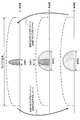
- FIG. 1A and 1B are diagrams showing an example of the relationship between BWP setting and CORESET setting according to the first embodiment.
- FIG. 2 is a diagram showing an example of a monitoring target at the time of BWP switching according to the second embodiment.
- FIG. 3 is a view showing another example of the monitoring target at the time of BWP switching according to the second embodiment.
- FIG. 4 is a diagram showing an example of a schematic configuration of a wireless communication system according to an embodiment.
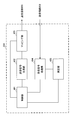
- FIG. 5 is a diagram showing an example of the entire configuration of the radio base station according to an embodiment.
- FIG. 6 is a diagram showing an example of a functional configuration of a wireless base station according to an embodiment.
- FIG. 7 is a diagram showing an example of the entire configuration of a user terminal according to an embodiment.
- FIG. 8 is a diagram showing an example of a functional configuration of a user terminal according to an embodiment.
- FIG. 9 is a diagram illustrating an example of a hardware configuration of a radio base station and
- BWP BandWidth Part
- CC Component Carrier
- BWP used for DL communication may be called DL BWP
- BWP used for UL communication may be called UL BWP.
- the UE may assume that, of the configured BWPs, one BWP (one DL BWP and one UL BWP) is active (available) at a given time. Also, the DL BWP and UL BWP may have frequency bands overlapping with each other.
- the UE performs reception in the active DL BWP using the terminology associated with the DL BWP, and transmits in the active UL BWP using the terminology associated with the UL BWP.
- the BWP configuration may be a number, a frequency position (for example, a center frequency), a bandwidth (for example, the number of resource blocks (also called RB (Resource Block), PRB (Physical RB), etc.)), time resources (for example). For example, information such as slot (minislot) index, period) may be included.
- the BWP configuration may be notified, for example, by higher layer signaling.
- upper layer signaling may be, for example, any of Radio Resource Control (RRC) signaling, Medium Access Control (MAC) signaling, broadcast information, and the like, or a combination thereof.
- RRC Radio Resource Control
- MAC Medium Access Control
- the MAC signaling may use, for example, a MAC control element (MAC CE (Control Element)), a MAC PDU (Protocol Data Unit), or the like.
- the broadcast information may be, for example, a master information block (MIB), a system information block (SIB), a minimum system information (RMSI), and the like.
- At least one of the configured DL BWPs may include a control resource set (CORESET: COntrol REsource SET) of a common search space.
- CORESET COntrol REsource SET
- CORESET is an allocation candidate area of a control channel (for example, PDCCH (Physical Downlink Control Channel)), and is a control subband, a control space set, a search space resource set, a control area, a control subband, NR-PDCCH It may be called an area or the like.
- a control channel for example, PDCCH (Physical Downlink Control Channel)
- PDCCH Physical Downlink Control Channel
- each of the configured DL BWPs may include a CORESET of UE-specific search space.
- the control channel is a physical layer control signal (for example, downlink control information (DCI: Downlink Control Information)), a base station (for example, BS (Base Station), transmission / reception point (TRP: Transmission / Reception Point), eNB (eNodeB) , GNB (NR Node B) and so on may be used to transmit to the UE.
- DCI Downlink Control Information
- BS Base Station
- TRP Transmission / Reception Point
- eNB eNodeB
- GNB NR Node B
- the DCI may be, for example, a resource (time and / or frequency resource) of scheduled data, a transport block (eg, transport block size (TBS)), modulation and / or coding scheme, delivery confirmation information ( For example, it may be scheduling information including information on at least one of retransmission control information, HARQ-ACK, ACK / NACK, etc.), a demodulation reference signal (DMRS) for data demodulation, and the like.
- a resource time and / or frequency resource
- a transport block eg, transport block size (TBS)
- modulation and / or coding scheme e.g, a transport block size (TBS)
- delivery confirmation information For example, it may be scheduling information including information on at least one of retransmission control information, HARQ-ACK, ACK / NACK, etc.
- DMRS demodulation reference signal
- DCI that schedules DL data e.g., Physical Downlink Shared Channel (PDSCH)
- DL assignment e.g., Physical Downlink Shared Channel (PDSCH)
- DL DCI DL assignment
- DL grant DL DCI
- DL DCI for scheduling transmission of UL data for example, PUSCH: Physical Uplink Shared Channel (PUSCH)
- PUSCH Physical Uplink Shared Channel
- UL sounding (for measurement) signals may be referred to as UL grant, UL DCI, and so on.
- the UE may receive CORESET configuration information (which may be referred to as CORESET configuration) from the radio base station.
- CORESET configuration information
- the UE can detect the physical layer control signal by monitoring the CORESET set in the UE.
- the CORESET configuration may be notified, for example, by higher layer signaling (eg, RRC signaling, SIB, etc.).
- higher layer signaling eg, RRC signaling, SIB, etc.
- CORESET settings include CORESET frequency resources (eg, number of RBs), time resources (eg, starting OFDM symbol number), duration (duration), REG (Resource Element Group) bundle size (REG size), transmission type (eg, CORESET related parameters such as interleaving, non-interleaving), period (for example, monitoring period every CORESET) may be included (which may be called CORESET parameter, PDCCH monitoring parameter, etc.).
- CORESET frequency resources eg, number of RBs
- time resources eg, starting OFDM symbol number
- duration duration
- REG (Resource Element Group) bundle size REG size
- transmission type eg, CORESET related parameters such as interleaving, non-interleaving
- period for example, monitoring period every CORESET
- PDCCH monitoring parameter PDCCH monitoring parameter, etc.
- search space related parameters (which may be referred to as search space configuration, search space parameters, etc.) may be configured for the UE.
- the search space parameters may be notified, for example, by higher layer signaling (eg, RRC signaling).
- Search space parameters may be included in the CORESET setting.
- the CORESET setting may be referred to as a search space setting.
- the search space parameter is a parameter for specifying a hash function used to derive the search space, a parameter used for the hash function, a parameter for cyclic redundancy check (CRC: cyclic redundancy check) masking (for example, a UE identifier (for example, A UE-ID (Identifier), a Radio Network Temporary Identifier (RNTI), a virtual UE-ID, etc. may be included.
- CRC cyclic redundancy check
- the inventors have conceived of a setting method in the case of performing control based on BWP.
- BWP in the description of this specification may be read as “at least one of DL BWP and UL BWP”.
- monitoring of CORESET in the description of the present specification may be read as “monitor of search space (downlink control channel candidate) associated with CORESET or downlink control channel (for example, PDCCH)”.
- the first embodiment relates to the association of BWP settings and CORESET settings.
- the first embodiment can be roughly divided into two.
- One is an embodiment (embodiment 1.1) in which the BWP setting includes one or more CORESET settings.
- FIG. 1A and 1B are diagrams showing an example of the relationship between BWP setting and CORESET setting according to the first embodiment.
- FIG. 1A corresponds to embodiment 1.1.
- BWP setting 1 eg, DL BWP setting
- CORESET settings 1 and 2 are CORESET settings 1 and 2.
- Each BWP configuration signaled by higher layer signaling may be configured to include one or more CORESET settings, respectively.
- FIG. 1B corresponds to embodiment 1.2.
- BWP setting 1 eg, DL BWP setting
- the CORESET setting includes information indicating (specifying) the relevant BWP setting.
- each of the CORESET settings 1 and 2 includes information indicating that the associated BWP setting is '1' (BWP setting 1).
- CORESET settings may be associated with the same BWP setting or may be associated with different BWP settings.
- Each CORESET setting notified by upper layer signaling may be configured to include information for identifying one or more associated BWP settings, respectively. For example, if CORESET setting 1 is used in BWP setting 1 and BWP setting 2, CORESET setting 1 may include information indicating BWP settings 1 and 2 as information indicating related BWP settings.
- the information indicating the related BWP setting may include, for example, an index of BWP, and may include information indicating at least one of frequency resources (eg, center frequency, bandwidth, PRB index, etc.) corresponding to BWP.
- frequency resources eg, center frequency, bandwidth, PRB index, etc.
- the BWP setting may not include the CORESET setting directly, but may include information indicating (specifying) the related CORESET setting.
- the CORESET setting may be configured to directly include the BWP setting instead of including the information indicating the related BWP setting.
- configurations may be employed where one or more BWP settings include a CORESET setting, while one or more CORESET settings include a BWP setting.
- the association based on either the BWP setting or the CORESET setting may be prioritized, or both associations may be used.
- the UE can appropriately perform transmission and reception according to the scheduling of the base station by appropriately grasping the correspondence between BWP and CORESET.
- BWP switching refers to switching of an active BWP, and the name is not limited thereto.
- BWP switching may be indicated by predetermined signaling (for example, any one or a combination of RRC signaling, MAC signaling, DCI, etc.) or may be performed based on a predetermined timer.
- the UE may switch an active BWP when a plurality of BWPs are set in advance and DCI indicating BWP switching (for example, DL assignment, UL grant, etc.) is received.
- DCI indicating BWP switching for example, DL assignment, UL grant, etc.
- Such control may be referred to as scheduling DCI-based active BWP switching.
- BWP switching may be instructed by the DCI scheduling a resource of size 0 (in this case, the UE may not perform transmission and reception simultaneously with BWP switching).
- the UE may switch the active BWP if the timer for BWP switching has expired. For example, the UE may deactivate an active BWP and activate a predetermined BWP (eg, a default BWP) when the timer expires. Such control may be referred to as timer-based active BWP switching.
- a predetermined BWP eg, a default BWP
- the default BWP may be predetermined according to the specification (for example, may be assumed to be the first used or initially set BWP), or may be set by higher layer signaling or the like. Also, information on the timer (time to expiration, timer start condition, etc.) may be set by higher layer signaling or the like.
- the transition period of BWP switching (which may also be referred to as BWP switching period) corresponds, for example, to the start of DCI transmission or reception indicating BWP switching, or from the expiration of the timer for BWP switching, to the UE responding to a new BWP CORESET. It may be defined as a time difference between the start of monitoring of attached search space or PDCCH.
- the BWP switching period may be referred to as a vague period.
- the BWP switching period may be, for example, 1 ms, or may be a period corresponding to a predetermined number of symbols (14 symbols, 28 symbols, etc.).
- the BWP switching period may be determined based on UE Capability for RF retuning.
- the UE determines CORESET including PDCCH candidates to be monitored.
- the method of associating BWP (BWP setting) with CORESET (CORESET setting) in the second embodiment may be the method described above in the first embodiment.
- the UE monitors CORESET for an active BWP (active DL BWP) (embodiment 2.1). If the base station wants the UE to monitor both CORESET for active BWP before BWP switching and CORESET for new active BWP after BWP switching, configure the base station to associate the new active BWP with both of these CORESETs. You can do
- the UE in embodiment 2.1 may assume that only the new BWP after BWP switching is active in the ambiguous period. In the present specification, "assuming” may be replaced with “assume”.
- the UE monitors CORESET for an active BWP (active DL BWP).
- the UE monitors both CORESET for the active BWP before BWP switching and CORESET for the new active BWP after BWP switching in the BWP switching period (embodiment 2.2).
- the amount of information for associating BWP and CORESET can be reduced.
- the UE monitors CORESET for an active BWP (active DL BWP). Also, in the BWP switching period, one of the active BWP before BWP switching and the new active BWP after BWP switching is a subset (eg, including) of the other or a superset of the other (eg, If included, monitor CORESET for both BWPs (embodiment 2.3). In the case of the embodiment 2.3, failure in monitoring PDCCH can be suppressed because frequency retuning may not be necessary for CORESET monitoring.
- Embodiments 2.2 and / or 2.3 may be applied when the active BWP before and after BWP switching correspond to the same numerology, or are applied when they correspond to different numerology It is also good.
- IFFTs fast inverse Fourier transforms
- the candidate band of BWP such as switching between BWP in the low frequency band and BWP in the high frequency band.
- eMBB enhanced mobile broad band
- URLLC ultra reliable and low latency communication
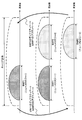
- FIG. 2 is a diagram showing an example of a monitoring target at the time of BWP switching according to the second embodiment.
- the transition from the top to the bottom of the figure indicates switching from BWP1 to BWP2 (deactivation of BWP1 & activation of BWP2), and the reverse transition is switching from BWP2 to BWP1 (deactivation of BWP2). & Activate BWP1).
- the middle of FIG. 2 corresponds to the ambiguous period.
- the UE can monitor the CORESET of each BWP in the ambiguity period, for example, based on the method of embodiments 2.2, 2.3 and so on.
- FIG. 3 is a view showing another example of the monitoring target at the time of BWP switching according to the second embodiment.
- the transition from the top to the bottom of the figure indicates switching from BWP1 to BWP2 (deactivation of BWP1 & activation of BWP2), and the reverse transition is switching from BWP2 to BWP1 (deactivation of BWP2). & Activate BWP1).
- the middle of FIG. 3 corresponds to the ambiguous period.
- BWP1 corresponds to Neumerology 1
- BWP2 corresponds to Neumerology 2.
- the UE can monitor the CORESET of each BWP in the ambiguity period, for example, based on the method of Embodiment 2.2 or the like.
- the UE may assume that all of the multiple BWPs are active. In an ambiguous period, there may be multiple active BWPs.
- the UE may treat a predetermined subband including the plurality of BWPs as one BWP.
- a BWP that includes a plurality of BWPs and is treated as one BWP may be referred to as an extended BWP, a switching period BWP, or the like.
- the UE may assume that in the switching period, the active BWP is an extended BWP.
- the UE may assume that at least one of the multiple BWPs is inactive. However, the UE may monitor CORESET in a BWP assumed to be such inactive.
- Such inactive and CORESET monitoring states may be referred to as semi-active states, semi-activated states, monitoring states, and the like.
- the UE performs less operations than in the active BWP, such as not monitoring the PDCCH and not transmitting the PUCCH.
- the UE can appropriately determine the CORESET to monitor even during the ambiguous period associated with BWP switching.
- wireless communication system Wireless communication system
- communication is performed using any one or a combination of the wireless communication methods according to the above embodiments of the present disclosure.
- FIG. 4 is a diagram showing an example of a schematic configuration of a wireless communication system according to an embodiment.
- the radio communication system 1 applies carrier aggregation (CA) and / or dual connectivity (DC) in which a plurality of basic frequency blocks (component carriers) each having a system bandwidth (for example, 20 MHz) of the LTE system as one unit are integrated. can do.
- CA carrier aggregation
- DC dual connectivity
- the wireless communication system 1 includes LTE (Long Term Evolution), LTE-A (LTE-Advanced), LTE-B (LTE-Beyond), SUPER 3G, IMT-Advanced, 4G (4th generation mobile communication system), and 5G. It may be called (5th generation mobile communication system), NR (New Radio), FRA (Future Radio Access), New-RAT (Radio Access Technology) or the like, or may be called a system for realizing these.
- the radio communication system 1 includes a radio base station 11 forming a macrocell C1 with a relatively wide coverage, and radio base stations 12 (12a to 12c) disposed in the macrocell C1 and forming a small cell C2 narrower than the macrocell C1. And. Moreover, the user terminal 20 is arrange
- the user terminal 20 can be connected to both the radio base station 11 and the radio base station 12. It is assumed that the user terminal 20 simultaneously uses the macro cell C1 and the small cell C2 using CA or DC. Also, the user terminal 20 may apply CA or DC using a plurality of cells (CCs).
- CCs a plurality of cells
- Communication can be performed between the user terminal 20 and the radio base station 11 using a relatively low frequency band (for example, 2 GHz) and a narrow bandwidth carrier (also called an existing carrier, legacy carrier, etc.).
- a carrier having a wide bandwidth in a relatively high frequency band for example, 3.5 GHz, 5 GHz, etc.
- the configuration of the frequency band used by each wireless base station is not limited to this.
- the user terminal 20 can perform communication in each cell using time division duplex (TDD) and / or frequency division duplex (FDD). Also, in each cell (carrier), a single numerology may be applied, or a plurality of different numerologies may be applied.
- TDD time division duplex
- FDD frequency division duplex
- Numerology may be communication parameters applied to transmission and / or reception of a certain signal and / or channel, for example, subcarrier spacing, bandwidth, symbol length, cyclic prefix length, subframe length It may indicate at least one of TTI length, number of symbols per TTI, radio frame configuration, specific filtering processing performed by the transceiver in the frequency domain, and specific windowing processing performed by the transceiver in the time domain. For example, in the case where subcarrier intervals of constituent OFDM symbols are different and / or the number of OFDM symbols is different for a certain physical channel, the neurology may be referred to as different.
- the wireless base station 11 and the wireless base station 12 are connected by wire (for example, an optical fiber conforming to CPRI (Common Public Radio Interface), X2 interface, etc.) or wirelessly It may be done.
- wire for example, an optical fiber conforming to CPRI (Common Public Radio Interface), X2 interface, etc.
- CPRI Common Public Radio Interface
- X2 interface etc.
- the radio base station 11 and each radio base station 12 are connected to the higher station apparatus 30 and connected to the core network 40 via the higher station apparatus 30.
- the upper station apparatus 30 includes, for example, an access gateway apparatus, a radio network controller (RNC), a mobility management entity (MME), and the like, but is not limited thereto. Further, each wireless base station 12 may be connected to the higher station apparatus 30 via the wireless base station 11.
- RNC radio network controller
- MME mobility management entity
- the radio base station 11 is a radio base station having a relatively wide coverage, and may be called a macro base station, an aggregation node, an eNB (eNodeB), a transmission / reception point, or the like.
- the radio base station 12 is a radio base station having local coverage, and is a small base station, a micro base station, a pico base station, a femto base station, a HeNB (Home eNodeB), an RRH (Remote Radio Head), transmission and reception It may be called a point or the like.
- the radio base stations 11 and 12 are not distinguished, they are collectively referred to as the radio base station 10.
- Each user terminal 20 is a terminal compatible with various communication schemes such as LTE and LTE-A, and may include not only mobile communication terminals (mobile stations) but also fixed communication terminals (fixed stations).
- orthogonal frequency division multiple access (OFDMA) is applied to the downlink as a radio access scheme, and single carrier frequency division multiple access (SC-FDMA: single carrier) to the uplink.
- SC-FDMA single carrier frequency division multiple access
- Frequency Division Multiple Access and / or OFDMA is applied.
- OFDMA is a multicarrier transmission scheme in which a frequency band is divided into a plurality of narrow frequency bands (subcarriers) and data is mapped to each subcarrier to perform communication.
- SC-FDMA is a single carrier transmission that reduces interference between terminals by dividing the system bandwidth into a band configured by one or continuous resource blocks for each terminal, and a plurality of terminals use different bands. It is a system.
- the uplink and downlink radio access schemes are not limited to these combinations, and other radio access schemes may be used.
- a downlink shared channel (PDSCH: Physical Downlink Shared Channel) shared by each user terminal 20, a broadcast channel (PBCH: Physical Broadcast Channel), a downlink L1 / L2 control channel, etc. are used as downlink channels. Used. User data, upper layer control information, SIB (System Information Block), etc. are transmitted by the PDSCH. Also, a MIB (Master Information Block) is transmitted by the PBCH.
- PDSCH Physical Downlink Shared Channel
- PBCH Physical Broadcast Channel
- SIB System Information Block
- MIB Master Information Block
- the downlink L1 / L2 control channel includes PDCCH (Physical Downlink Control Channel), EPDCCH (Enhanced Physical Downlink Control Channel), PCFICH (Physical Control Format Indicator Channel), PHICH (Physical Hybrid-ARQ Indicator Channel) and the like.
- Downlink control information (DCI) including scheduling information of PDSCH and / or PUSCH is transmitted by PDCCH.
- scheduling information may be notified by DCI.
- DCI scheduling DL data reception may be referred to as DL assignment
- DCI scheduling UL data transmission may be referred to as UL grant.
- the number of OFDM symbols used for PDCCH is transmitted by PCFICH.
- Delivery confirmation information (for example, also referred to as retransmission control information, HARQ-ACK, and ACK / NACK) of HARQ (Hybrid Automatic Repeat reQuest) for the PUSCH is transmitted by the PHICH.
- the EPDCCH is frequency division multiplexed with a PDSCH (downlink shared data channel), and is used for transmission such as DCI, similarly to the PDCCH.
- an uplink shared channel (PUSCH: Physical Uplink Shared Channel) shared by each user terminal 20, an uplink control channel (PUCCH: Physical Uplink Control Channel), a random access channel (PRACH: Physical Random Access Channel) or the like is used.
- User data, upper layer control information, etc. are transmitted by PUSCH.
- downlink radio quality information (CQI: Channel Quality Indicator), delivery confirmation information, scheduling request (SR: Scheduling Request) and the like are transmitted by the PUCCH.
- the PRACH transmits a random access preamble for establishing a connection with a cell.
- a cell-specific reference signal (CRS: Cell-specific Reference Signal), a channel state information reference signal (CSI-RS: Channel State Information-Reference Signal), a demodulation reference signal (DMRS: DeModulation Reference Signal, positioning reference signal (PRS), etc.
- CRS Cell-specific Reference Signal
- CSI-RS Channel State Information-Reference Signal
- DMRS DeModulation Reference Signal
- PRS positioning reference signal
- SRS Sounding Reference Signal
- DMRS demodulation reference signal
- PRS positioning reference signal
- DMRS Demodulation reference signal
- PRS positioning reference signal
- FIG. 5 is a diagram showing an example of the entire configuration of the radio base station according to an embodiment.
- the radio base station 10 includes a plurality of transmitting and receiving antennas 101, an amplifier unit 102, a transmitting and receiving unit 103, a baseband signal processing unit 104, a call processing unit 105, and a transmission path interface 106. Note that each of the transmitting and receiving antenna 101, the amplifier unit 102, and the transmitting and receiving unit 103 may be configured to include one or more.
- User data transmitted from the radio base station 10 to the user terminal 20 by downlink is input from the higher station apparatus 30 to the baseband signal processing unit 104 via the transmission path interface 106.
- the baseband signal processing unit 104 performs packet data convergence protocol (PDCP) layer processing, user data division / combination, RLC layer transmission processing such as RLC (Radio Link Control) retransmission control, and MAC (Medium Access) for user data.
- Control Transmission processing such as retransmission control (for example, HARQ transmission processing), scheduling, transmission format selection, channel coding, inverse fast Fourier transform (IFFT) processing, precoding processing, etc. It is transferred to 103. Further, transmission processing such as channel coding and inverse fast Fourier transform is also performed on the downlink control signal and transferred to the transmission / reception unit 103.
- the transmission / reception unit 103 converts the baseband signal output from the baseband signal processing unit 104 for each antenna into a radio frequency band and transmits the baseband signal.
- the radio frequency signal frequency-converted by the transmitting and receiving unit 103 is amplified by the amplifier unit 102 and transmitted from the transmitting and receiving antenna 101.
- the transmission / reception unit 103 can be configured of a transmitter / receiver, a transmission / reception circuit, or a transmission / reception device described based on the common recognition in the technical field according to the present disclosure.
- the transmitting and receiving unit 103 may be configured as an integrated transmitting and receiving unit, or may be configured from a transmitting unit and a receiving unit.
- the radio frequency signal received by the transmission / reception antenna 101 is amplified by the amplifier unit 102.
- the transmitting and receiving unit 103 receives the upstream signal amplified by the amplifier unit 102.
- the transmission / reception unit 103 frequency-converts the received signal into a baseband signal and outputs the result to the baseband signal processing unit 104.
- the baseband signal processing unit 104 performs Fast Fourier Transform (FFT) processing, Inverse Discrete Fourier Transform (IDFT) processing, and error correction on user data included in the input upstream signal. Decoding, reception processing of MAC retransmission control, and reception processing of RLC layer and PDCP layer are performed, and are transferred to the higher station apparatus 30 via the transmission path interface 106.
- the call processing unit 105 performs call processing (setting, release, etc.) of the communication channel, state management of the radio base station 10, management of radio resources, and the like.
- the transmission path interface 106 transmits and receives signals to and from the higher station apparatus 30 via a predetermined interface. Also, the transmission path interface 106 transmits / receives signals (backhaul signaling) to / from the other wireless base station 10 via an inter-base station interface (for example, an optical fiber conforming to CPRI (Common Public Radio Interface), X2 interface). May be
- an inter-base station interface for example, an optical fiber conforming to CPRI (Common Public Radio Interface), X2 interface.
- the transmission / reception unit 103 may transmit downlink control information (for example, DCI) in a control resource set (CORESET: COntrol REsource SET) related to an active bandwidth portion (BWP: Band Width Part).
- DCI downlink control information
- CORESET COntrol REsource SET
- BWP Band Width Part
- the transmission / reception unit 103 may transmit, to the user terminal 20, BWP setting, CORESET setting, information on BWP switching, and the like.
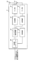
- FIG. 6 is a diagram illustrating an example of a functional configuration of a wireless base station according to an embodiment of the present disclosure.
- the functional block of the characteristic part in this embodiment is mainly shown, and it may be assumed that the wireless base station 10 also has another functional block required for wireless communication.
- the baseband signal processing unit 104 at least includes a control unit (scheduler) 301, a transmission signal generation unit 302, a mapping unit 303, a reception signal processing unit 304, and a measurement unit 305. Note that these configurations may be included in the wireless base station 10, and some or all of the configurations may not be included in the baseband signal processing unit 104.
- a control unit (scheduler) 301 performs control of the entire radio base station 10.
- the control unit 301 can be configured of a controller, a control circuit, or a control device described based on the common recognition in the technical field according to the present disclosure.
- the control unit 301 controls, for example, generation of a signal in the transmission signal generation unit 302, assignment of a signal in the mapping unit 303, and the like. Further, the control unit 301 controls reception processing of a signal in the reception signal processing unit 304, measurement of a signal in the measurement unit 305, and the like.
- the control unit 301 schedules (for example, resources) system information, downlink data signals (for example, signals transmitted on PDSCH), downlink control signals (for example, signals transmitted on PDCCH and / or EPDCCH, delivery confirmation information, etc.) Control allocation). Further, the control unit 301 controls generation of the downlink control signal, the downlink data signal, and the like based on the result of determining whether the retransmission control for the uplink data signal is necessary or not.
- the control unit 301 controls scheduling of synchronization signals (for example, PSS (Primary Synchronization Signal) / SSS (Secondary Synchronization Signal), downlink reference signals (for example, CRS, CSI-RS, DMRS) and the like.
- synchronization signals for example, PSS (Primary Synchronization Signal) / SSS (Secondary Synchronization Signal)
- SSS Secondary Synchronization Signal
- CRS Channel Reference Signal
- CSI-RS CSI-RS
- DMRS Downlink reference signals
- the control unit 301 may use an uplink data signal (for example, a signal transmitted on PUSCH), an uplink control signal (for example, a signal transmitted on PUCCH and / or PUSCH, delivery confirmation information, etc.), a random access preamble (for example, PRACH). Control the scheduling of transmitted signals, uplink reference signals, etc.
- an uplink data signal for example, a signal transmitted on PUSCH
- an uplink control signal for example, a signal transmitted on PUCCH and / or PUSCH, delivery confirmation information, etc.
- a random access preamble for example, PRACH
- the control unit 301 may schedule an active BWP of the user terminal 20.
- the control unit 301 may perform control to transmit DCI in CORESET related to the active BWP.
- the transmission signal generation unit 302 generates a downlink signal (downlink control signal, downlink data signal, downlink reference signal or the like) based on an instruction from the control unit 301, and outputs the downlink signal to the mapping unit 303.
- the transmission signal generation unit 302 can be configured from a signal generator, a signal generation circuit, or a signal generation device described based on the common recognition in the technical field according to the present disclosure.
- the transmission signal generation unit 302 generates, for example, DL assignment for notifying downlink data allocation information and / or UL grant for notifying uplink data allocation information, based on an instruction from the control unit 301.
- DL assignment and UL grant are both DCI and follow DCI format.
- coding processing and modulation processing are performed on the downlink data signal according to a coding rate, a modulation method, and the like determined based on channel state information (CSI: Channel State Information) and the like from each user terminal 20.
- CSI Channel State Information
- Mapping section 303 maps the downlink signal generated by transmission signal generation section 302 to a predetermined radio resource based on an instruction from control section 301, and outputs the mapped downlink signal to transmission / reception section 103.
- the mapping unit 303 can be configured from a mapper, a mapping circuit or a mapping device described based on the common recognition in the technical field according to the present disclosure.
- the reception signal processing unit 304 performs reception processing (for example, demapping, demodulation, decoding, and the like) on the reception signal input from the transmission / reception unit 103.
- the reception signal is, for example, an uplink signal (uplink control signal, uplink data signal, uplink reference signal, etc.) transmitted from the user terminal 20.
- the received signal processing unit 304 can be configured from a signal processor, a signal processing circuit or a signal processing device described based on the common recognition in the technical field according to the present disclosure.
- the reception signal processing unit 304 outputs the information decoded by the reception process to the control unit 301. For example, when the PUCCH including the HARQ-ACK is received, the HARQ-ACK is output to the control unit 301. Further, the reception signal processing unit 304 outputs the reception signal and / or the signal after reception processing to the measurement unit 305.
- the measurement unit 305 performs measurement on the received signal.
- the measuring unit 305 can be configured from a measuring device, a measuring circuit, or a measuring device described based on the common recognition in the technical field according to the present disclosure.
- the measurement unit 305 may perform Radio Resource Management (RRM) measurement, Channel State Information (CSI) measurement, and the like based on the received signal.
- the measurement unit 305 may use received power (for example, reference signal received power (RSRP)), received quality (for example, reference signal received quality (RSRQ), signal to interference plus noise ratio (SINR), signal to noise ratio (SNR)). , Signal strength (e.g., received signal strength indicator (RSSI)), channel information (e.g., CSI), and the like.
- RSRP reference signal received power
- RSSI received signal strength indicator
- CSI channel information
- the measurement result may be output to the control unit 301.
- FIG. 7 is a diagram showing an example of the entire configuration of a user terminal according to an embodiment.
- the user terminal 20 includes a plurality of transmitting and receiving antennas 201, an amplifier unit 202, a transmitting and receiving unit 203, a baseband signal processing unit 204, and an application unit 205.
- each of the transmitting and receiving antenna 201, the amplifier unit 202, and the transmitting and receiving unit 203 may be configured to include one or more.
- the radio frequency signal received by the transmission / reception antenna 201 is amplified by the amplifier unit 202.
- the transmitting and receiving unit 203 receives the downlink signal amplified by the amplifier unit 202.
- the transmission / reception unit 203 frequency-converts the received signal into a baseband signal and outputs the result to the baseband signal processing unit 204.
- the transmission / reception unit 203 can be configured of a transmitter / receiver, a transmission / reception circuit, or a transmission / reception device described based on the common recognition in the technical field according to the present disclosure.
- the transmission / reception unit 203 may be configured as an integrated transmission / reception unit, or may be configured from a transmission unit and a reception unit.
- the baseband signal processing unit 204 performs reception processing of FFT processing, error correction decoding, retransmission control, and the like on the input baseband signal.
- the downlink user data is transferred to the application unit 205.
- the application unit 205 performs processing on a layer higher than the physical layer and the MAC layer. Moreover, broadcast information may also be transferred to the application unit 205 among downlink data.
- uplink user data is input from the application unit 205 to the baseband signal processing unit 204.
- the baseband signal processing unit 204 performs transmission processing of retransmission control (for example, transmission processing of HARQ), channel coding, precoding, discrete Fourier transform (DFT) processing, IFFT processing, etc. It is transferred to 203.
- the transmission / reception unit 203 converts the baseband signal output from the baseband signal processing unit 204 into a radio frequency band and transmits it.
- the radio frequency signal frequency-converted by the transmitting and receiving unit 203 is amplified by the amplifier unit 202 and transmitted from the transmitting and receiving antenna 201.
- the transmission / reception unit 203 may monitor a control resource set (CORESET: COntrol REsource SET) associated with an active bandwidth portion (BWP: Band Width Part).
- CORESET COntrol REsource SET
- BWP Band Width Part
- the transmission / reception unit 203 may receive, from the radio base station 10, BWP setting, CORESET setting, information on BWP switching, and the like.
- the information on BWP switching may include information (for example, DCI) instructing BWP switching, or information on a timer for BWP switching.
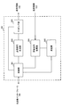
- FIG. 8 is a diagram showing an example of a functional configuration of a user terminal according to an embodiment.
- the functional block of the characteristic part in this embodiment is mainly shown, and it may be assumed that the user terminal 20 also has another functional block required for wireless communication.
- the baseband signal processing unit 204 included in the user terminal 20 at least includes a control unit 401, a transmission signal generation unit 402, a mapping unit 403, a reception signal processing unit 404, and a measurement unit 405. Note that these configurations may be included in the user terminal 20, and some or all of the configurations may not be included in the baseband signal processing unit 204.
- the control unit 401 controls the entire user terminal 20.
- the control unit 401 can be configured of a controller, a control circuit, or a control device described based on the common recognition in the technical field according to the present disclosure.
- the control unit 401 controls, for example, generation of a signal in the transmission signal generation unit 402, assignment of a signal in the mapping unit 403, and the like. Further, the control unit 401 controls reception processing of signals in the reception signal processing unit 404, measurement of signals in the measurement unit 405, and the like.
- the control unit 401 acquires the downlink control signal and the downlink data signal transmitted from the radio base station 10 from the reception signal processing unit 404.
- the control unit 401 controls the generation of the uplink control signal and / or the uplink data signal based on the result of determining the necessity of the retransmission control for the downlink control signal and / or the downlink data signal.
- the control unit 401 may determine the association between the BWP setting and the CORESET setting.
- the control unit 401 may determine CORESET to be monitored when the BWP is active, based on the information of the BWP setting and / or the CORESET setting.
- the control unit 401 determines CORESET to be monitored in a period (switching period) during switching of the active BWP from the first BWP (active BWP before switching) to the second BWP (active BWP after switching). Good.
- control unit 401 when the first BWP is associated with the first CORESET and the second BWP is associated with the first CORESET and the second CORESET, the control unit 401 performs the first CORESET in the period. And control which monitors both the said 2nd CORESET may be performed.
- the control unit 401 monitors the target after switching in the switching period. Control may be performed to monitor each CORESET.
- control unit 401 controls the first CORESET and the second CORESET during the period. Control may be performed to monitor both of the two CORESETs.
- control unit 401 may perform control to monitor each CORESET to be monitored before switching in the switching period, regardless of the CORESET to be monitored after switching.
- control unit 401 When the first BWP is associated with the first CORESET and the second BWP is associated with the second CORESET, the control unit 401 causes both the first CORESET and the second CORESET in the period. Control to monitor the
- control unit 401 may perform control to monitor each CORESET to be monitored before and after the switching in the switching period.
- control unit 401 When one of the first BWP and the second BWP includes the other, the control unit 401 causes the first CORESET associated with the first BWP and the second associated with the second BWP in the above period. Control to monitor both of CORESET may be performed.
- control unit 401 may perform control to monitor each CORESET to be monitored before and after switching in the switching period.
- control unit 401 When the control unit 401 acquires various types of information notified from the radio base station 10 from the received signal processing unit 404, the control unit 401 may update parameters used for control based on the information.
- the transmission signal generation unit 402 generates an uplink signal (uplink control signal, uplink data signal, uplink reference signal or the like) based on an instruction from the control unit 401, and outputs the uplink signal to the mapping unit 403.
- the transmission signal generation unit 402 can be configured from a signal generator, a signal generation circuit or a signal generation device described based on the common recognition in the technical field according to the present disclosure.
- the transmission signal generation unit 402 generates, for example, an uplink control signal related to delivery confirmation information, channel state information (CSI), and the like based on an instruction from the control unit 401. Further, the transmission signal generation unit 402 generates an uplink data signal based on an instruction from the control unit 401. For example, when the downlink control signal notified from the radio base station 10 includes a UL grant, the transmission signal generation unit 402 is instructed by the control unit 401 to generate an uplink data signal.
- CSI channel state information
- Mapping section 403 maps the uplink signal generated by transmission signal generation section 402 to a radio resource based on an instruction from control section 401, and outputs the uplink signal to transmission / reception section 203.
- the mapping unit 403 can be configured from a mapper, a mapping circuit, or a mapping device described based on the common recognition in the technical field according to the present disclosure.
- the reception signal processing unit 404 performs reception processing (for example, demapping, demodulation, decoding, and the like) on the reception signal input from the transmission / reception unit 203.
- the reception signal is, for example, a downlink signal (a downlink control signal, a downlink data signal, a downlink reference signal, or the like) transmitted from the radio base station 10.
- the received signal processing unit 404 can be configured from a signal processor, a signal processing circuit or a signal processing device described based on the common recognition in the technical field according to the present disclosure. Further, the received signal processing unit 404 can configure a receiving unit according to the present disclosure.
- the reception signal processing unit 404 outputs the information decoded by the reception process to the control unit 401.
- the received signal processing unit 404 outputs, for example, broadcast information, system information, RRC signaling, DCI, and the like to the control unit 401. Further, the reception signal processing unit 404 outputs the reception signal and / or the signal after reception processing to the measurement unit 405.
- the measurement unit 405 performs measurement on the received signal.
- the measuring unit 405 can be configured from a measuring instrument, a measuring circuit or a measuring device described based on the common recognition in the technical field according to the present disclosure.
- the measurement unit 405 may perform RRM measurement, CSI measurement, and the like based on the received signal.
- the measurement unit 405 may measure reception power (for example, RSRP), reception quality (for example, RSRQ, SINR, SNR), signal strength (for example, RSSI), channel information (for example, CSI), and the like.
- the measurement result may be output to the control unit 401.
- each functional block (components) are realized by any combination of hardware and / or software.
- the implementation method of each functional block is not particularly limited. That is, each functional block may be realized using one physically and / or logically coupled device, or directly and / or two or more physically and / or logically separated devices. Or it may connect indirectly (for example, using a wire communication and / or radio), and it may be realized using a plurality of these devices.
- a wireless base station, a user terminal, and the like in an embodiment of the present disclosure may function as a computer that performs the processing of the wireless communication method of the present disclosure.
- FIG. 9 is a diagram illustrating an example of a hardware configuration of a radio base station and a user terminal according to an embodiment.
- the above-described wireless base station 10 and user terminal 20 may be physically configured as a computer device including a processor 1001, a memory 1002, a storage 1003, a communication device 1004, an input device 1005, an output device 1006, a bus 1007 and the like. Good.
- the term “device” can be read as a circuit, a device, a unit, or the like.
- the hardware configuration of the radio base station 10 and the user terminal 20 may be configured to include one or more of the devices illustrated in the figure, or may be configured without including some devices.
- processor 1001 may be implemented by one or more chips.
- Each function in the radio base station 10 and the user terminal 20 is calculated by causing the processor 1001 to read predetermined software (program) on hardware such as the processor 1001 and the memory 1002, and the communication device 1004 is performed. This is realized by controlling communication, and controlling reading and / or writing of data in the memory 1002 and the storage 1003.
- the processor 1001 operates, for example, an operating system to control the entire computer.
- the processor 1001 may be configured by a central processing unit (CPU) including an interface with a peripheral device, a control device, an arithmetic device, a register, and the like.
- CPU central processing unit
- the above-described baseband signal processing unit 104 (204), call processing unit 105, and the like may be realized by the processor 1001.
- the processor 1001 reads a program (program code), a software module, data, and the like from the storage 1003 and / or the communication device 1004 to the memory 1002, and executes various processing according to these.
- a program a program that causes a computer to execute at least a part of the operations described in the above-described embodiment is used.
- the control unit 401 of the user terminal 20 may be realized by a control program stored in the memory 1002 and operating in the processor 1001, or may be realized similarly for other functional blocks.
- the memory 1002 is a computer readable recording medium, and for example, at least at least a read only memory (ROM), an erasable programmable ROM (EPROM), an electrically EPROM (EEPROM), a random access memory (RAM), or any other suitable storage medium. It may be configured by one.
- the memory 1002 may be called a register, a cache, a main memory (main storage device) or the like.
- the memory 1002 may store a program (program code), a software module, and the like that can be executed to implement the wireless communication method according to an embodiment.
- the storage 1003 is a computer readable recording medium, and for example, a flexible disk, a floppy (registered trademark) disk, a magneto-optical disk (for example, a compact disk (CD-ROM (Compact Disc ROM), etc.), a digital versatile disk, Blu-ray® disc), removable disc, hard disc drive, smart card, flash memory device (eg card, stick, key drive), magnetic stripe, database, server, at least one other suitable storage medium May be configured by The storage 1003 may be called an auxiliary storage device.
- a computer readable recording medium for example, a flexible disk, a floppy (registered trademark) disk, a magneto-optical disk (for example, a compact disk (CD-ROM (Compact Disc ROM), etc.), a digital versatile disk, Blu-ray® disc), removable disc, hard disc drive, smart card, flash memory device (eg card, stick, key drive), magnetic stripe, database, server, at least one other suitable storage medium May be configured by
- the communication device 1004 is hardware (transmission / reception device) for performing communication between computers via a wired and / or wireless network, and is also called, for example, a network device, a network controller, a network card, a communication module, or the like.
- the communication device 1004 includes, for example, a high frequency switch, a duplexer, a filter, a frequency synthesizer, and the like to realize, for example, frequency division duplex (FDD) and / or time division duplex (TDD). It may be configured.
- FDD frequency division duplex
- TDD time division duplex
- the transmission / reception antenna 101 (201), the amplifier unit 102 (202), the transmission / reception unit 103 (203), the transmission path interface 106, and the like described above may be realized by the communication device 1004.
- the input device 1005 is an input device (for example, a keyboard, a mouse, a microphone, a switch, a button, a sensor, and the like) that receives an input from the outside.
- the output device 1006 is an output device (for example, a display, a speaker, a light emitting diode (LED) lamp, and the like) that performs output to the outside.
- the input device 1005 and the output device 1006 may be integrated (for example, a touch panel).
- each device such as the processor 1001 and the memory 1002 is connected by a bus 1007 for communicating information.
- the bus 1007 may be configured using a single bus, or may be configured using different buses between devices.
- radio base station 10 and the user terminal 20 may be microprocessors, digital signal processors (DSPs), application specific integrated circuits (ASICs), programmable logic devices (PLDs), field programmable gate arrays (FPGAs), etc.
- DSPs digital signal processors
- ASICs application specific integrated circuits
- PLDs programmable logic devices
- FPGAs field programmable gate arrays
- Hardware may be included, and part or all of each functional block may be realized using the hardware.
- processor 1001 may be implemented using at least one of these hardware.
- the channels and / or symbols may be signaling.
- the signal may be a message.
- the reference signal may be abbreviated as RS (Reference Signal), and may be referred to as a pilot (Pilot), a pilot signal or the like according to an applied standard.
- a component carrier CC: Component Carrier
- CC Component Carrier
- the radio frame may be configured by one or more periods (frames) in the time domain.
- Each of the one or more periods (frames) that constitute a radio frame may be referred to as a subframe.
- a subframe may be configured by one or more slots in the time domain.
- the subframes may be of a fixed time length (e.g., 1 ms) independent of the neurology.
- the slot may be configured by one or more symbols in the time domain (such as orthogonal frequency division multiplexing (OFDM) symbols, single carrier frequency division multiple access (SC-FDMA) symbols, etc.).
- the slot may be a time unit based on the neurology.
- the slot may include a plurality of minislots. Each minislot may be configured by one or more symbols in the time domain. Minislots may also be referred to as subslots.
- a radio frame, a subframe, a slot, a minislot and a symbol all represent time units when transmitting a signal.
- subframes, slots, minislots and symbols other names corresponding to each may be used.
- one subframe may be referred to as a transmission time interval (TTI)
- TTI transmission time interval
- a plurality of consecutive subframes may be referred to as a TTI
- one slot or one minislot may be referred to as a TTI.
- TTI transmission time interval
- the subframe and / or TTI may be a subframe (1 ms) in existing LTE, a period shorter than 1 ms (eg, 1-13 symbols), or a period longer than 1 ms. It may be.
- the unit representing TTI may be called a slot, a minislot, etc. instead of a subframe.
- TTI refers to, for example, the minimum time unit of scheduling in wireless communication.
- the radio base station performs scheduling to assign radio resources (frequency bandwidth usable in each user terminal, transmission power, etc.) to each user terminal in TTI units.
- radio resources frequency bandwidth usable in each user terminal, transmission power, etc.
- the TTI may be a transmission time unit of a channel encoded data packet (transport block), a code block, and / or a codeword, or may be a processing unit such as scheduling and link adaptation. Note that, when a TTI is given, the time interval (eg, the number of symbols) in which the transport block, the code block, and / or the codeword is actually mapped may be shorter than the TTI.
- one or more TTIs may be the minimum time unit of scheduling.
- the number of slots (the number of minislots) constituting the minimum time unit of the scheduling may be controlled.
- a TTI having a time length of 1 ms may be referred to as a normal TTI (TTI in LTE Rel. 8-12), a normal TTI, a long TTI, a normal subframe, a normal subframe, a long subframe, or the like.
- a TTI shorter than a normal TTI may be referred to as a shortened TTI, a short TTI, a partial TTI (partial or fractional TTI), a shortened subframe, a short subframe, a minislot, a subslot, or the like.
- a long TTI for example, a normal TTI, a subframe, etc.
- a short TTI eg, a shortened TTI, etc.
- a resource block is a resource allocation unit in time domain and frequency domain, and may include one or more consecutive subcarriers (subcarriers) in the frequency domain. Also, an RB may include one or more symbols in the time domain, and may be one slot, one minislot, one subframe, or one TTI in length. One TTI and one subframe may be respectively configured by one or more resource blocks. Note that one or more RBs may be a physical resource block (PRB: Physical RB), a subcarrier group (SCG: Sub-Carrier Group), a resource element group (REG: Resource Element Group), a PRB pair, an RB pair, etc. It may be called.
- PRB Physical resource block
- SCG Sub-Carrier Group
- REG Resource Element Group
- a resource block may be configured by one or more resource elements (RE: Resource Element).
- RE Resource Element
- one RE may be one subcarrier and one symbol radio resource region.
- the above-described structures such as the radio frame, subframe, slot, minislot and symbol are merely examples.
- the number of subframes included in a radio frame the number of slots per subframe or radio frame, the number of minislots included in a slot, the number of symbols and RBs included in a slot or minislot, included in an RB
- the number of subcarriers, as well as the number of symbols in a TTI, the symbol length, the cyclic prefix (CP) length, and other configurations can be variously changed.
- the information, parameters, etc. described in the present specification may be expressed using absolute values, may be expressed using relative values from predetermined values, or other corresponding information. May be represented.
- radio resources may be indicated by a predetermined index.
- the names used for parameters and the like in the present specification are not limited names in any respect.
- various channels PUCCH (Physical Uplink Control Channel), PDCCH (Physical Downlink Control Channel), etc.
- information elements can be identified by any suitable names, various assignments are made to these various channels and information elements.
- the name is not limited in any way.
- data, instructions, commands, information, signals, bits, symbols, chips etc may be voltage, current, electromagnetic waves, magnetic fields or particles, optical fields or photons, or any of these May be represented by a combination of
- information, signals, etc. may be output from the upper layer to the lower layer and / or from the lower layer to the upper layer.
- Information, signals, etc. may be input / output via a plurality of network nodes.
- the input / output information, signals and the like may be stored in a specific place (for example, a memory) or may be managed using a management table. Information, signals, etc. input and output can be overwritten, updated or added. The output information, signals and the like may be deleted. The input information, signals and the like may be transmitted to other devices.
- notification of information is not limited to the aspects / embodiments described herein, and may be performed using other methods.
- notification of information may be physical layer signaling (eg, downlink control information (DCI), uplink control information (UCI)), upper layer signaling (eg, RRC (Radio Resource Control) signaling, It may be implemented by broadcast information (Master Information Block (MIB), System Information Block (SIB), etc.), MAC (Medium Access Control) signaling, other signals, or a combination thereof.
- DCI downlink control information
- UCI uplink control information
- RRC Radio Resource Control
- MIB Master Information Block
- SIB System Information Block
- MAC Medium Access Control
- the physical layer signaling may be called L1 / L2 (Layer 1 / Layer 2) control information (L1 / L2 control signal), L1 control information (L1 control signal), or the like.
- RRC signaling may be referred to as an RRC message, and may be, for example, an RRC connection setup (RRC Connection Setup) message, an RRC connection reconfiguration (RRC Connection Reconfiguration) message, or the like.
- MAC signaling may be notified using, for example, a MAC control element (MAC CE (Control Element)).
- notification of predetermined information is not limited to explicit notification, but implicitly (for example, by not notifying the predetermined information or other information Notification may be performed).
- the determination may be performed by a value (0 or 1) represented by one bit, or may be performed by a boolean value represented by true or false. , Numerical comparison (for example, comparison with a predetermined value) may be performed.
- Software may be called software, firmware, middleware, microcode, hardware description language, or any other name, and may be instructions, instruction sets, codes, code segments, program codes, programs, subprograms, software modules. Should be interpreted broadly to mean applications, software applications, software packages, routines, subroutines, objects, executables, threads of execution, procedures, functions, etc.
- software, instructions, information, etc. may be sent and received via a transmission medium.
- software may use a wired technology (coaxial cable, fiber optic cable, twisted pair, digital subscriber line (DSL), etc.) and / or a wireless technology (infrared, microwave, etc.), a website, a server
- wired technology coaxial cable, fiber optic cable, twisted pair, digital subscriber line (DSL), etc.
- wireless technology infrared, microwave, etc.
- system and "network” as used herein are used interchangeably.
- base station Base Station
- radio base station eNB
- gNB gigad Generation
- cell cell
- cell group cell group
- carrier carrier
- carrier may be used interchangeably.
- a base station may also be called in terms of a fixed station (Node station), NodeB, eNodeB (eNB), access point (access point), transmission point, reception point, femtocell, small cell, and so on.
- a base station may accommodate one or more (e.g., three) cells (also called sectors). If the base station accommodates multiple cells, the entire coverage area of the base station can be partitioned into multiple smaller areas, each smaller area being a base station subsystem (eg, a small base station for indoor use (RRH: Communication service can also be provided by Remote Radio Head).
- RRH Communication service can also be provided by Remote Radio Head.
- the terms "cell” or “sector” refer to part or all of the coverage area of a base station and / or a base station subsystem serving communication services in this coverage.
- MS mobile station
- UE user equipment
- the mobile station may be a subscriber station, a mobile unit, a subscriber unit, a wireless unit, a remote unit, a mobile device, a wireless device, a wireless communication device, a remote device, a mobile subscriber station, an access terminal, a mobile terminal, a wireless terminal, by those skilled in the art. It may also be called a terminal, a remote terminal, a handset, a user agent, a mobile client, a client or some other suitable term.
- the radio base station in the present specification may be replaced with a user terminal.
- each aspect / embodiment of the present disclosure may be applied to a configuration in which communication between a wireless base station and a user terminal is replaced with communication between a plurality of user terminals (D2D: Device-to-Device).
- the user terminal 20 may have a function that the above-described radio base station 10 has.
- the wordings such as "up” and “down” may be read as "side".
- the upstream channel may be read as a side channel.
- a user terminal herein may be read at a radio base station.
- the radio base station 10 may have a function that the above-described user terminal 20 has.
- the operation supposed to be performed by the base station may be performed by its upper node in some cases.
- various operations performed for communication with a terminal may be a base station, one or more network nodes other than the base station (eg, It is apparent that this can be performed by MME (Mobility Management Entity), S-GW (Serving-Gateway), etc. but not limited thereto or a combination thereof.
- MME Mobility Management Entity
- S-GW Serving-Gateway
- Each aspect / embodiment described in the present specification includes LTE (Long Term Evolution), LTE-A (LTE-Advanced), LTE-B (LTE-Beyond), SUPER 3G, IMT-Advanced, 4G (4th generation mobile) Communication system), 5G (5th generation mobile communication system), FRA (Future Radio Access), New-RAT (Radio Access Technology), NR (New Radio), NX (New radio access), FX (Future generation radio access), GSM (registered trademark) (Global System for Mobile communications), CDMA2000, UMB (Ultra Mobile Broadband), IEEE 802.11 (Wi-Fi (registered trademark)), IEEE 802.16 (WiMAX (registered trademark)), IEEE 802 .20, UWB (Ultra-Wide Band), Bluetooth (registered trademark) And / or systems based on other suitable wireless communication methods and / or extended next generation systems based on these.
- LTE Long Term Evolution
- LTE-A Long Term Evolution-Advanced
- any reference to an element using the designation "first”, “second” and the like as used herein does not generally limit the quantity or order of those elements. These designations may be used herein as a convenient way of distinguishing between two or more elements. Thus, reference to the first and second elements does not mean that only two elements can be taken or that the first element must somehow precede the second element.
- determining may encompass a wide variety of operations. For example, “determination” may be calculating, computing, processing, deriving, investigating, looking up (eg, table, database or other data) A search on structure), ascertaining, etc. may be considered as “determining”. Also, “determination” may be receiving (e.g. receiving information), transmitting (e.g. transmitting information), input (input), output (output), access (access) It may be considered as “determining” (eg, accessing data in memory) and the like. Also, “determination” is considered to be “determination” to resolve, select, choose, choose, establish, compare, etc. It is also good. That is, “determination” may be considered as “determining” some action.
- connection refers to any direct or indirect connection between two or more elements or It means a bond and can include the presence of one or more intermediate elements between two elements “connected” or “connected” to each other.
- the coupling or connection between elements may be physical, logical or a combination thereof. For example, “connection” may be read as "access”.
- the radio frequency domain It can be considered as “connected” or “coupled” with one another using electromagnetic energy or the like having wavelengths in the microwave region and / or the light (both visible and invisible) regions.
- a and B are different may mean “A and B are different from each other”.
- the terms “leave”, “combined” and the like may be interpreted similarly.
Abstract
Description
<第1の実施形態>
第1の実施形態は、BWP設定及びCORESET設定の関連付けに関する。第1の実施形態は2つに大別できる。1つは、BWP設定が1つ又は複数のCORESET設定を含む実施形態(実施形態1.1)である。もう1つは、BWP設定が1つ又は複数のCORESET設定に関連付けられる実施形態(実施形態1.2)である。 (Wireless communication method)
First Embodiment
The first embodiment relates to the association of BWP settings and CORESET settings. The first embodiment can be roughly divided into two. One is an embodiment (embodiment 1.1) in which the BWP setting includes one or more CORESET settings. Another is an embodiment (embodiment 1.2) in which the BWP setting is associated with one or more CORESET settings.
第2の実施形態は、BWPスイッチングに関する。ここで、BWPスイッチングは、アクティブなBWPの切り替えのことをいい、呼称はこれに限られない。BWPスイッチングは、所定のシグナリング(例えば、RRCシグナリング、MACシグナリング、DCIなどのいずれか又はこれらの組み合わせ)によって指示されてもよいし、所定のタイマに基づいて行われてもよい。 Second Embodiment
The second embodiment relates to BWP switching. Here, BWP switching refers to switching of an active BWP, and the name is not limited thereto. BWP switching may be indicated by predetermined signaling (for example, any one or a combination of RRC signaling, MAC signaling, DCI, etc.) or may be performed based on a predetermined timer.
以下、本開示の一実施形態に係る無線通信システムの構成について説明する。この無線通信システムでは、本開示の上記各実施形態に係る無線通信方法のいずれか又はこれらの組み合わせを用いて通信が行われる。 (Wireless communication system)
Hereinafter, the configuration of a wireless communication system according to an embodiment of the present disclosure will be described. In this wireless communication system, communication is performed using any one or a combination of the wireless communication methods according to the above embodiments of the present disclosure.
図5は、一実施形態に係る無線基地局の全体構成の一例を示す図である。無線基地局10は、複数の送受信アンテナ101と、アンプ部102と、送受信部103と、ベースバンド信号処理部104と、呼処理部105と、伝送路インターフェース106と、を備えている。なお、送受信アンテナ101、アンプ部102、送受信部103は、それぞれ1つ以上を含むように構成されればよい。 (Wireless base station)
FIG. 5 is a diagram showing an example of the entire configuration of the radio base station according to an embodiment. The
図7は、一実施形態に係るユーザ端末の全体構成の一例を示す図である。ユーザ端末20は、複数の送受信アンテナ201と、アンプ部202と、送受信部203と、ベースバンド信号処理部204と、アプリケーション部205と、を備えている。なお、送受信アンテナ201、アンプ部202、送受信部203は、それぞれ1つ以上を含むように構成されればよい。 (User terminal)
FIG. 7 is a diagram showing an example of the entire configuration of a user terminal according to an embodiment. The
なお、上記実施形態の説明に用いたブロック図は、機能単位のブロックを示している。これらの機能ブロック(構成部)は、ハードウェア及び/又はソフトウェアの任意の組み合わせによって実現される。また、各機能ブロックの実現方法は特に限定されない。すなわち、各機能ブロックは、物理的及び/又は論理的に結合した1つの装置を用いて実現されてもよいし、物理的及び/又は論理的に分離した2つ以上の装置を直接的及び/又は間接的に(例えば、有線及び/又は無線を用いて)接続し、これら複数の装置を用いて実現されてもよい。 (Hardware configuration)
The block diagram used for the explanation of the above-mentioned embodiment has shown the block of a functional unit. These functional blocks (components) are realized by any combination of hardware and / or software. Moreover, the implementation method of each functional block is not particularly limited. That is, each functional block may be realized using one physically and / or logically coupled device, or directly and / or two or more physically and / or logically separated devices. Or it may connect indirectly (for example, using a wire communication and / or radio), and it may be realized using a plurality of these devices.
なお、本明細書において説明した用語及び/又は本明細書の理解に必要な用語については、同一の又は類似する意味を有する用語と置き換えてもよい。例えば、チャネル及び/又はシンボルは信号(シグナリング)であってもよい。また、信号はメッセージであってもよい。参照信号は、RS(Reference Signal)と略称することもでき、適用される標準によってパイロット(Pilot)、パイロット信号などと呼ばれてもよい。また、コンポーネントキャリア(CC:Component Carrier)は、セル、周波数キャリア、キャリア周波数などと呼ばれてもよい。 (Modification)
The terms described in the present specification and / or the terms necessary for the understanding of the present specification may be replaced with terms having the same or similar meanings. For example, the channels and / or symbols may be signaling. Also, the signal may be a message. The reference signal may be abbreviated as RS (Reference Signal), and may be referred to as a pilot (Pilot), a pilot signal or the like according to an applied standard. Also, a component carrier (CC: Component Carrier) may be called a cell, a frequency carrier, a carrier frequency or the like.
Claims (5)
- アクティブな帯域幅部分(BWP:BandWidth Part)に関連する制御リソースセット(CORESET:COntrol REsource SET)をモニタする受信部と、
前記アクティブなBWPを第1のBWPから第2のBWPに切り替える間の期間においてモニタするCORESETを判断する制御部と、を有することを特徴とするユーザ端末。 A receiver for monitoring a set of control resources (CORESET: COntrol REsource SET) associated with an active bandwidth part (BWP);
A control unit which determines CORESET to monitor during a period between switching the first BWP to the second BWP; - 前記制御部は、前記第1のBWPが第1のCORESETに関連付けられ、前記第2のBWPが前記第1のCORESET及び第2のCORESETに関連付けられる場合に、前記期間において、前記第1のCORESET及び前記第2のCORESETの両方をモニタする制御を行うことを特徴とする請求項1に記載のユーザ端末。 The control unit is configured to, during the period, when the first BWP is associated with the first CORESET and the second BWP is associated with the first CORESET and the second CORESET. The user terminal according to claim 1, wherein control to monitor both the second CORESET and the second CORESET is performed.
- 前記制御部は、前記第1のBWPが第1のCORESETに関連付けられ、前記第2のBWPが第2のCORESETに関連付けられる場合に、前記期間において、前記第1のCORESET及び前記第2のCORESETの両方をモニタする制御を行うことを特徴とする請求項1に記載のユーザ端末。 The control unit is configured to, during the period, when the first BWP is associated with a first CORESET and the second BWP is associated with a second CORESET, the first CORESET and the second CORESET. The user terminal according to claim 1, characterized in that control to monitor both is performed.
- 前記制御部は、前記第1のBWP及び前記第2のBWPの一方が他方を包含する場合、前記期間において、前記第1のBWPに関連付けられる第1のCORESET及び前記第2のBWPに関連付けられる第2のCORESETの両方をモニタする制御を行うことを特徴とする請求項1に記載のユーザ端末。 The control unit is associated with a first CORESET associated with the first BWP and the second BWP in the period when one of the first BWP and the second BWP includes the other. The user terminal according to claim 1, wherein control to monitor both of the second CORESET is performed.
- アクティブな帯域幅部分(BWP:BandWidth Part)に関連するCORESETをモニタするステップと、
前記アクティブなBWPを第1のBWPから第2のBWPに切り替える間の期間においてモニタするCORESETを判断するステップと、を有することを特徴とする無線通信方法。
Monitoring CORESET associated with an active bandwidth portion (BWP);
Determining CORESET to monitor in a period between switching of the active BWP from the first BWP to the second BWP.
Priority Applications (6)
| Application Number | Priority Date | Filing Date | Title |
|---|---|---|---|
| PCT/JP2017/041340 WO2019097643A1 (en) | 2017-11-16 | 2017-11-16 | User terminal and wireless communications method |
| EP17932030.4A EP3713298A4 (en) | 2017-11-16 | 2017-11-16 | User terminal and wireless communications method |
| JP2019554122A JP7074766B2 (en) | 2017-11-16 | 2017-11-16 | Terminals, wireless communication methods and systems |
| US16/763,141 US11589340B2 (en) | 2017-11-16 | 2017-11-16 | User terminal and radio communication method |
| CN201780098136.2A CN111615843B (en) | 2017-11-16 | 2017-11-16 | Terminal, wireless communication method and system |
| KR1020207014541A KR102456057B1 (en) | 2017-11-16 | 2017-11-16 | User terminal and wireless communication method |
Applications Claiming Priority (1)
| Application Number | Priority Date | Filing Date | Title |
|---|---|---|---|
| PCT/JP2017/041340 WO2019097643A1 (en) | 2017-11-16 | 2017-11-16 | User terminal and wireless communications method |
Publications (1)
| Publication Number | Publication Date |
|---|---|
| WO2019097643A1 true WO2019097643A1 (en) | 2019-05-23 |
Family
ID=66539469
Family Applications (1)
| Application Number | Title | Priority Date | Filing Date |
|---|---|---|---|
| PCT/JP2017/041340 WO2019097643A1 (en) | 2017-11-16 | 2017-11-16 | User terminal and wireless communications method |
Country Status (6)
| Country | Link |
|---|---|
| US (1) | US11589340B2 (en) |
| EP (1) | EP3713298A4 (en) |
| JP (1) | JP7074766B2 (en) |
| KR (1) | KR102456057B1 (en) |
| CN (1) | CN111615843B (en) |
| WO (1) | WO2019097643A1 (en) |
Cited By (3)
| Publication number | Priority date | Publication date | Assignee | Title |
|---|---|---|---|---|
| WO2020261395A1 (en) * | 2019-06-25 | 2020-12-30 | 株式会社Nttドコモ | Terminal and wireless communication method |
| JP2021515995A (en) * | 2018-01-11 | 2021-06-24 | オッポ広東移動通信有限公司Guangdong Oppo Mobile Telecommunications Corp., Ltd. | Resource configuration method and device |
| WO2021168814A1 (en) * | 2020-02-28 | 2021-09-02 | Oppo广东移动通信有限公司 | Control channel determination method and apparatus, and storage medium and processor |
Families Citing this family (10)
| Publication number | Priority date | Publication date | Assignee | Title |
|---|---|---|---|---|
| WO2019095251A1 (en) * | 2017-11-17 | 2019-05-23 | Qualcomm Incorporated | Control plane design for bandwidth part in new radio |
| CN116886255A (en) * | 2017-11-24 | 2023-10-13 | 鸿颖创新有限公司 | Base station and method performed by the base station |
| PL3866376T3 (en) * | 2018-01-09 | 2023-02-20 | Beijing Xiaomi Mobile Software Co., Ltd. | Physical and mac layer processes in a wireless device |
| US11006442B2 (en) * | 2018-02-13 | 2021-05-11 | Mediatek Singapore Pte. Ltd. | Method and apparatus for bandwidth part switch operations in mobile communications |
| CN111465109B (en) * | 2018-03-14 | 2024-04-05 | 迪朵无线创新有限公司 | User equipment, method and device in base station for wireless communication |
| KR20210038570A (en) * | 2018-07-27 | 2021-04-07 | 광동 오포 모바일 텔레커뮤니케이션즈 코포레이션 리미티드 | Transmission resource determination method and device, terminal device |
| EP3627910A1 (en) * | 2018-09-21 | 2020-03-25 | Comcast Cable Communications LLC | Activation and deactivation of power saving operation |
| US20210377988A1 (en) * | 2018-11-05 | 2021-12-02 | Apple Inc. | Mechanisms for bandwidth part (bwp) switching in a new radio (nr) network |
| WO2020163985A1 (en) * | 2019-02-11 | 2020-08-20 | 北京小米移动软件有限公司 | Channel monitoring method and device |
| CN115604839B (en) * | 2022-11-29 | 2023-04-07 | 中国移动紫金(江苏)创新研究院有限公司 | Method, device, base station and electronic equipment for switching and scheduling partial bandwidth BWP |
Family Cites Families (18)
| Publication number | Priority date | Publication date | Assignee | Title |
|---|---|---|---|---|
| US10172125B2 (en) * | 2014-04-28 | 2019-01-01 | Sharp Kabushiki Kaisha | Terminal device, base station device, communication method, and integrated circuit |
| JP6896705B2 (en) * | 2015-08-21 | 2021-06-30 | 華為技術有限公司Huawei Technologies Co.,Ltd. | Wireless communication methods, network devices, user devices, and systems |
| FI20155664A (en) * | 2015-09-16 | 2017-03-17 | Gistele Oy | Protective cover for connecting electrical and / or telecommunication cables to several objects |
| US10148337B2 (en) * | 2017-02-01 | 2018-12-04 | Samsung Electronics Co., Ltd. | Beam management of downlink data channel and downlink control channel for 5G next radio systems |
| US10750569B2 (en) * | 2017-03-03 | 2020-08-18 | Qualcomm Incorporated | Beam management for connected mode discontinuous reception operation |
| KR102313704B1 (en) * | 2017-05-04 | 2021-10-18 | 광동 오포 모바일 텔레커뮤니케이션즈 코포레이션 리미티드 | Method and apparatus for discontinuous reception |
| US10588171B2 (en) * | 2017-05-12 | 2020-03-10 | Qualcomm Incorporated | Techniques for multi-state DRX in new radio |
| CN110870374B (en) * | 2017-07-06 | 2023-05-26 | Lg电子株式会社 | Method and apparatus for processing multiple parameter sets in a wireless communication system |
| US10728002B2 (en) * | 2017-08-10 | 2020-07-28 | Huawei Technologies Co., Ltd. | System and method for enabling reliable and low latency communication |
| WO2019032009A1 (en) * | 2017-08-11 | 2019-02-14 | Telefonaktiebolaget Lm Ericsson (Publ) | Systems and methods for adaptively monitoring downlink control channel in discontinuous reception |
| WO2019061080A1 (en) * | 2017-09-27 | 2019-04-04 | Oppo广东移动通信有限公司 | Bandwidth part switching method, terminal device, and computer storage medium |
| US10594468B2 (en) * | 2017-09-29 | 2020-03-17 | Mediatek Inc. | Efficient bandwidth adaptation for a wideband carrier |
| US10887073B2 (en) * | 2017-10-26 | 2021-01-05 | Ofinno, Llc | Activation and deactivation of bandwidth part |
| EP3568946A1 (en) * | 2017-10-26 | 2019-11-20 | Ofinno, LLC | Bandwidth part inactivity timer |
| KR102210412B1 (en) * | 2017-10-30 | 2021-02-01 | 엘지전자 주식회사 | Method for determining a resource area allocated to a bandwidth portion in a wireless communication system, and apparatus therefor |
| CN109729590A (en) * | 2017-10-31 | 2019-05-07 | 华硕电脑股份有限公司 | Improve the method and apparatus of the power consumption of starting cell in wireless communication system |
| US10869312B2 (en) * | 2017-10-31 | 2020-12-15 | Ofinno, Llc | Scheduling with bandwidth part switching |
| WO2019094781A2 (en) * | 2017-11-09 | 2019-05-16 | Ofinno Technologies, Llc | Communications based on wireless device capabilities |
-
2017
- 2017-11-16 JP JP2019554122A patent/JP7074766B2/en active Active
- 2017-11-16 EP EP17932030.4A patent/EP3713298A4/en not_active Withdrawn
- 2017-11-16 US US16/763,141 patent/US11589340B2/en active Active
- 2017-11-16 WO PCT/JP2017/041340 patent/WO2019097643A1/en unknown
- 2017-11-16 CN CN201780098136.2A patent/CN111615843B/en active Active
- 2017-11-16 KR KR1020207014541A patent/KR102456057B1/en active IP Right Grant
Non-Patent Citations (5)
| Title |
|---|
| "Evolved Universal Terrestrial Radio Access (E-UTRA) and Evolved Universal Terrestrial Radio Access Network (E-UTRAN); Overall description; Stage 2 (Release 8", 3GPP TS 36.300, April 2010 (2010-04-01) |
| "Summary of Bandwidth Part Operation", 3GPP TSG-RAN WG1#90B R1-1718901, 9 October 2017 (2017-10-09), XP051353382, Retrieved from the Internet <URL:http://www.3gpp.org/ftp/TSG_RAN/WG1_RL1/TSGR1_90b/Docs/R1-1718901.zip> * |
| INTERDIGITAL INC: "RLM/RLF for NR", 3GPP TSG-RAN WG2#98 R2-1704920, 15 May 2017 (2017-05-15), pages 1, 2, XP051265107, Retrieved from the Internet <URL:http://www.3gpp.org/ftp/tsg_ran/WG2_RL2/TSGR2_98/Docs/R2-1704920.zip> * |
| SAMSUNG: "RLM/RLF for bandwidth part", 3GPP TSG-RAN WG2 #99B R2-1711404, 9 October 2017 (2017-10-09), XP051343389, Retrieved from the Internet <URL:http://www.3gpp.org/ftp/TSG_RAN/WG2_RL2/TSGR2_99bis/Docs/R2-1711404.zip> * |
| SAMSUNG: "RRM measurement bandwidth in NR", 3GPP TSG-RAN WG2#98 R2-1704507, 15 May 2017 (2017-05-15), XP051263610, Retrieved from the Internet <URL:http://www.3gpp.org/ftp/tsg_ran/WG2_RL2/TSGR2-98/Docs/R2-1704507.zip> * |
Cited By (3)
| Publication number | Priority date | Publication date | Assignee | Title |
|---|---|---|---|---|
| JP2021515995A (en) * | 2018-01-11 | 2021-06-24 | オッポ広東移動通信有限公司Guangdong Oppo Mobile Telecommunications Corp., Ltd. | Resource configuration method and device |
| WO2020261395A1 (en) * | 2019-06-25 | 2020-12-30 | 株式会社Nttドコモ | Terminal and wireless communication method |
| WO2021168814A1 (en) * | 2020-02-28 | 2021-09-02 | Oppo广东移动通信有限公司 | Control channel determination method and apparatus, and storage medium and processor |
Also Published As
| Publication number | Publication date |
|---|---|
| US20200280970A1 (en) | 2020-09-03 |
| CN111615843A (en) | 2020-09-01 |
| JP7074766B2 (en) | 2022-05-24 |
| JPWO2019097643A1 (en) | 2020-12-17 |
| CN111615843B (en) | 2023-09-26 |
| US11589340B2 (en) | 2023-02-21 |
| EP3713298A4 (en) | 2021-07-21 |
| KR20200083506A (en) | 2020-07-08 |
| KR102456057B1 (en) | 2022-10-19 |
| EP3713298A1 (en) | 2020-09-23 |
Similar Documents
| Publication | Publication Date | Title |
|---|---|---|
| JP7074766B2 (en) | Terminals, wireless communication methods and systems | |
| JP7248594B2 (en) | Terminal, wireless communication method, base station and system | |
| JP7111721B2 (en) | Terminal, wireless communication method, base station and system | |
| JP7121053B2 (en) | Terminal, wireless communication method, base station and system | |
| WO2019097646A1 (en) | User terminal and wireless communications method | |
| WO2019049282A1 (en) | User terminal and radio communication method | |
| WO2019021443A1 (en) | User terminal and radio communication method | |
| WO2019087340A1 (en) | User equipment and wireless communication method | |
| WO2019193688A1 (en) | User terminal and wireless communication method | |
| WO2019111301A1 (en) | User equipment and radio communication method | |
| WO2019138528A1 (en) | User terminal and wireless communication method | |
| JPWO2019193700A1 (en) | User terminal and wireless base station | |
| WO2019021489A1 (en) | User terminal and radio communication method | |
| WO2019171518A1 (en) | User terminal and wireless communication method | |
| WO2019069471A1 (en) | User terminal and wireless communication method | |
| WO2019026157A1 (en) | User terminal and wireless communications method | |
| WO2019026214A1 (en) | User terminal and wireless communications method | |
| WO2019176032A1 (en) | User equipment and wireless communication method | |
| WO2019026215A1 (en) | User terminal, wireless base station, and wireless communications method | |
| CN111758245B (en) | Terminal, system and wireless communication method | |
| WO2018143388A1 (en) | User terminal and wireless communication method | |
| WO2019102599A1 (en) | User equipment and wireless communication method | |
| WO2019138555A1 (en) | User terminal and wireless communication method | |
| WO2019021473A1 (en) | Transmission device, reception device, and wireless communication method | |
| WO2019142272A1 (en) | User terminal and wireless communication method |
Legal Events
| Date | Code | Title | Description |
|---|---|---|---|
| 121 | Ep: the epo has been informed by wipo that ep was designated in this application |
Ref document number: 17932030 Country of ref document: EP Kind code of ref document: A1 |
|
| ENP | Entry into the national phase |
Ref document number: 2019554122 Country of ref document: JP Kind code of ref document: A |
|
| NENP | Non-entry into the national phase |
Ref country code: DE |
|
| ENP | Entry into the national phase |
Ref document number: 20207014541 Country of ref document: KR Kind code of ref document: A |
|
| ENP | Entry into the national phase |
Ref document number: 2017932030 Country of ref document: EP Effective date: 20200616 |