WO2019131567A1 - 路面状態判別装置 - Google Patents
路面状態判別装置 Download PDFInfo
- Publication number
- WO2019131567A1 WO2019131567A1 PCT/JP2018/047408 JP2018047408W WO2019131567A1 WO 2019131567 A1 WO2019131567 A1 WO 2019131567A1 JP 2018047408 W JP2018047408 W JP 2018047408W WO 2019131567 A1 WO2019131567 A1 WO 2019131567A1
- Authority
- WO
- WIPO (PCT)
- Prior art keywords
- road surface
- data
- tire
- feature
- unit
- Prior art date
- Legal status (The legal status is an assumption and is not a legal conclusion. Google has not performed a legal analysis and makes no representation as to the accuracy of the status listed.)
- Ceased
Links
Images


Classifications
-
- B—PERFORMING OPERATIONS; TRANSPORTING
- B60—VEHICLES IN GENERAL
- B60C—VEHICLE TYRES; TYRE INFLATION; TYRE CHANGING; CONNECTING VALVES TO INFLATABLE ELASTIC BODIES IN GENERAL; DEVICES OR ARRANGEMENTS RELATED TO TYRES
- B60C99/00—Subject matter not provided for in other groups of this subclass
-
- B—PERFORMING OPERATIONS; TRANSPORTING
- B60—VEHICLES IN GENERAL
- B60C—VEHICLE TYRES; TYRE INFLATION; TYRE CHANGING; CONNECTING VALVES TO INFLATABLE ELASTIC BODIES IN GENERAL; DEVICES OR ARRANGEMENTS RELATED TO TYRES
- B60C19/00—Tyre parts or constructions not otherwise provided for
-
- B—PERFORMING OPERATIONS; TRANSPORTING
- B60—VEHICLES IN GENERAL
- B60C—VEHICLE TYRES; TYRE INFLATION; TYRE CHANGING; CONNECTING VALVES TO INFLATABLE ELASTIC BODIES IN GENERAL; DEVICES OR ARRANGEMENTS RELATED TO TYRES
- B60C23/00—Devices for measuring, signalling, controlling, or distributing tyre pressure or temperature, specially adapted for mounting on vehicles; Arrangement of tyre inflating devices on vehicles, e.g. of pumps or of tanks; Tyre cooling arrangements
-
- G—PHYSICS
- G01—MEASURING; TESTING
- G01H—MEASUREMENT OF MECHANICAL VIBRATIONS OR ULTRASONIC, SONIC OR INFRASONIC WAVES
- G01H11/00—Measuring mechanical vibrations or ultrasonic, sonic or infrasonic waves by detecting changes in electric or magnetic properties
- G01H11/06—Measuring mechanical vibrations or ultrasonic, sonic or infrasonic waves by detecting changes in electric or magnetic properties by electric means
- G01H11/08—Measuring mechanical vibrations or ultrasonic, sonic or infrasonic waves by detecting changes in electric or magnetic properties by electric means using piezoelectric devices
-
- G—PHYSICS
- G01—MEASURING; TESTING
- G01W—METEOROLOGY
- G01W1/00—Meteorology
-
- B—PERFORMING OPERATIONS; TRANSPORTING
- B60—VEHICLES IN GENERAL
- B60C—VEHICLE TYRES; TYRE INFLATION; TYRE CHANGING; CONNECTING VALVES TO INFLATABLE ELASTIC BODIES IN GENERAL; DEVICES OR ARRANGEMENTS RELATED TO TYRES
- B60C19/00—Tyre parts or constructions not otherwise provided for
- B60C2019/004—Tyre sensors other than for detecting tyre pressure
-
- G—PHYSICS
- G01—MEASURING; TESTING
- G01P—MEASURING LINEAR OR ANGULAR SPEED, ACCELERATION, DECELERATION, OR SHOCK; INDICATING PRESENCE, ABSENCE, OR DIRECTION, OF MOVEMENT
- G01P15/00—Measuring acceleration; Measuring deceleration; Measuring shock, i.e. sudden change of acceleration
Definitions
- the present disclosure detects the vibration received by the tire with the tire side device, creates road surface data indicating the road surface state based on the vibration data, transmits it to the vehicle body side system, and determines the road surface state based on the road surface data.
- the present invention relates to a road surface state determination device.
- Patent Document 1 there is provided a road surface state determining apparatus including an acceleration sensor on the back of the tire tread, detecting the vibration applied to the tire by the acceleration sensor, and estimating the road surface state based on the detection result of the vibration. Proposed.
- this road surface state determination device data regarding the road surface state is created based on the vibration waveform of the tire detected by the acceleration sensor, and the data of each wheel is transmitted to a receiver on the vehicle body side to estimate the road surface state. ing.
- a feature vector is extracted from the vibration waveform of the tire detected by the acceleration sensor, and this is used as data on the road surface condition.
- the feature vector is obtained by dividing the detection signal of the acceleration sensor for each time window of a predetermined time width and extracting the frequency component of the detection signal for each divided time window. Then, all the extracted feature vectors are transmitted to the receiver on the vehicle body side, and the degree of similarity is calculated between the feature vectors and all the support vectors stored for each type of road surface to determine the road surface state.
- the kernel function is used to calculate the degree of similarity between the extracted feature vector and all the support vectors, and the kind of road surface having the highest degree of similarity, eg, dry road surface, wet road surface, etc. It is to be determined.
- the road surface condition can not be determined with high responsiveness, and the driver can not be notified immediately of the road surface condition, or the vehicle response can not be controlled with high responsiveness according to the road surface condition. .
- the tire side device since the tire side device is provided at a position physically separated from the vehicle body, it is required to reduce the power consumption in the power supply unit, but the power consumption increases as the transmission time becomes longer. In particular, when a battery is used as a power supply unit, battery replacement is not easy and reduction in power consumption is required, and thus it is not preferable that the power consumption is increased.
- An object of the present disclosure is to provide a road surface state determining device capable of shortening a transmission time when data is transmitted from a tire side device.
- the road surface state determining device includes a tire side device attached to a plurality of tires provided in a vehicle and a vehicle body side system provided in a vehicle body, and the tire side device vibrates the tire.
- a waveform detection unit that outputs a detection signal corresponding to the size of the road
- a waveform processing unit that extracts data representing a road surface state indicated by tire vibration during one rotation of the tire from the detection signal, and Data having a high degree of characteristic representing a road surface condition is selected from the inside
- a control unit having a data selection unit for generating road surface data including a part of data during one rotation of the selected tire, and road surface data are transmitted
- a second data communication unit for receiving the road surface data transmitted from the first data communication unit; and a part of data included in the road surface data. Based on includes a road surface discriminator for discriminating the road surface condition, the.
- road surface data including a part of data during one rotation of the tire is transmitted from the tire side device, and the road surface state is determined by the vehicle body side system based on the road surface data. For this reason, it becomes possible to shorten the transmission time when transmitting data from the tire side device.
- the parenthesized reference symbol attached to each component etc. shows an example of the correspondence of the component etc. and the specific component etc. as described in the embodiment to be described later.
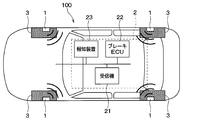
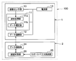
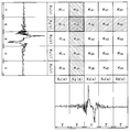
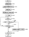
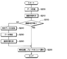
- FIG. 1 It is a figure showing the block configuration in the vehicles mounting state of the tire system by which the tire side device concerning a 1st embodiment was applied. It is a block diagram showing details of a tire side device and a vehicle body side system. It is a cross-sectional schematic diagram of the tire in which the tire side apparatus was attached. It is an output voltage waveform figure of the acceleration acquisition part at the time of tire rotation. It is a figure which shows a mode that the detection signal of the acceleration acquisition part was divided for every time window of predetermined time width
- the determinant Xi (r), Xi (s) and the distance in each section obtained by dividing the time axis waveform at the time of the current rotation of the tire and the time axis waveform at the time of one rotation before by each time window of a predetermined time width T It is the figure which showed the relationship with K yz . It is the figure which showed the relationship between the determinants Xi (r) and Xi (s) which demonstrated the calculation method of the similarity at the time of selecting the feature-value of area
- a tire system 100 having a road surface condition determination function according to the present embodiment will be described with reference to FIGS. 1 to 9.
- the tire system 100 according to the present embodiment determines the road surface state during traveling based on the vibration applied to the contact surface of the tire provided on each wheel of the vehicle, and notifies of the danger of the vehicle or the vehicle based on the road surface state. It performs exercise control and the like.
- the tire system 100 is configured to have a tire side device 1 provided on the wheel side and a vehicle body side system 2 including each part provided on the vehicle body side.
- a receiver 21 an electronic control unit for brake control (hereinafter referred to as a brake ECU) 22, a notification unit 23 and the like are provided.
- the part of the tire system 100 that implements the road surface state determination function corresponds to the road surface state determination device.
- the receiver 21 of the tire side device 1 and the vehicle body side system 2 constitutes a road surface state determining device.
- the tire system 100 transmits data (hereinafter referred to as road surface data) according to the road surface condition in which the tire 3 is traveling from the tire side device 1 and receives road surface data by the receiver 21 To determine the In addition, the tire system 100 transmits the determination result of the road surface condition in the receiver 21 to the notification device 23, and causes the notification device 23 to notify the determination result of the road surface condition.
- road surface data data (hereinafter referred to as road surface data) according to the road surface condition in which the tire 3 is traveling from the tire side device 1 and receives road surface data by the receiver 21
- the tire system 100 transmits the determination result of the road surface condition in the receiver 21 to the notification device 23, and causes the notification device 23 to notify the determination result of the road surface condition.
- This makes it possible to convey the road surface condition to the driver, for example, being a dry road, a wet road, a snow road or a frozen road, and to warn the driver if it is a slippery road surface.
- the tire system 100 transmits a road surface state to the brake ECU 22 or the like that performs vehicle motion control so that vehicle motion control for avoiding a danger is performed. For example, at the time of freezing, the braking force generated for the amount of brake operation is reduced as compared to the case of the dry road, so that the vehicle motion control can be matched when the road surface ⁇ is low.
- the tire side device 1 and the vehicle body side system 2 are configured as follows.
- the tire side device 1 is configured to include a vibration sensor unit 10, a control unit 11, a data communication unit 12 and a power supply unit 13 as shown in FIG. 2, and as shown in FIG. Provided on the back side of the tire side device 1
- the vibration sensor unit 10 constitutes a vibration detection unit for detecting a vibration applied to the tire 3.
- the vibration sensor unit 10 is configured by an acceleration sensor.
- the vibration sensor unit 10 is an acceleration sensor, the magnitude of the vibration in the direction in which the tire 3 contacts the circular track drawn by the tire-side device 1 when the tire 3 rotates, that is, the tire tangential direction indicated by arrow X in FIG.
- the detection signal of acceleration is output as a detection signal according to. More specifically, the vibration sensor unit 10 generates, as a detection signal, an output voltage or the like in which one of the two directions indicated by the arrow X is positive and the opposite direction is negative.
- the vibration sensor unit 10 performs acceleration detection at a predetermined sampling cycle set to a cycle shorter than one rotation of the tire 3 and outputs it as a detection signal.
- the detection signal of the vibration sensor unit 10 is represented as an output voltage or an output current, here, a case where it is represented as an output voltage is taken as an example.
- the control unit 11 is constituted by a known microcomputer provided with a CPU, ROM, RAM, I / O and the like, performs signal processing of detection signals according to a program stored in the ROM and the like, and indicates road surface conditions appearing in the detection signals. Generate road surface data.
- the control unit 11 is configured to include a waveform processing unit 11a and a data selection unit 11b as functional units that perform those processes.
- the waveform processing unit 11a is configured by a well-known microcomputer including a CPU, ROM, RAM, I / O, etc., performs signal processing of detection signals according to a program stored in the ROM or the like, and detects road surface conditions appearing in the detection signals.
- the road surface data to be shown is generated.
- the waveform processing unit 11a uses the detection signal output from the vibration sensor unit 10 as the detection signal representing the vibration data in the tire tangential direction, and performs waveform processing of the vibration waveform indicated by the detection signal. Extract the feature value of tire vibration.
- the feature amount of the tire G is extracted by performing signal processing on a detection signal of the acceleration of the tire 3 (hereinafter referred to as a tire G). The details of the feature quantities referred to here will be described later.
- the data selection unit 11 b selects a part of data to be transmitted to the vehicle body side system 2 from the data of the feature amount extracted by the waveform processing unit 11 a, and generates data including the feature amount of the part as road surface data And communicate to the data communication unit 12. Further, the data selection unit 11 b receives the instruction data from the vehicle body side system 2 and switches the data selection method based on the instruction data. In the case of the present embodiment, the data selection unit 11b normally selects the data with the highest feature degree from the data of the feature amounts extracted by the waveform processing unit 11a, and selects all the feature amounts when receiving the instruction data. . The details of the data selection method by the data selection unit 11b will be described later.
- the waveform processing unit 11a and the data selection unit 11b control data transmission from the data communication unit 12, and transmit road surface data to the data communication unit 12 at the timing when it is desired to perform data transmission.
- Data communication is performed from the communication unit 12.
- the waveform processing unit 11a and the data selection unit 11b the extraction of the feature amount of the tire G and the selection of data are performed each time the tire 3 makes one rotation or a plurality of rotations.
- the data selection unit 11 b transmits road surface data including data of the selected feature amount to the data communication unit 12 at a rate of one time or multiple times per rotation or multiple rotations of the tire 3.
- the data communication unit 12 is a part configuring the first data communication unit, and for example, when road surface data is transmitted from the data selection unit 11 b, the road surface data is transmitted at the timing.
- the timing of data transmission from the data communication unit 12 is controlled by the waveform processing unit 11 a and the data selection unit 11 b. Then, data transmission from the data communication unit 12 is performed each time road surface data is sent from the data selection unit 11 b each time the tire 3 rotates a plurality of times.
- the data communication unit 12 is also capable of bidirectional communication, and also plays a role of receiving data sent from the vehicle body side system 2. For example, the data communication unit 12 receives instruction data from the vehicle body side system 2 and transmits it to the data selection unit 11 b.
- Bluetooth communication including BLE (abbreviation of Bluetooth Low Energy) communication, wireless LAN such as wifi (abbreviation of Local Area Network), Sub-GHz, etc. Communication, ultra-wide band communication, ZigBee, etc. can be applied.
- BLE abbreviation of Bluetooth Low Energy
- wireless LAN such as wifi (abbreviation of Local Area Network), Sub-GHz, etc.
- Communication ultra-wide band communication, ZigBee, etc. can be applied.
- Bluetooth is a "registered trademark”.
- the power supply unit 13 is a power supply of the tire-side device 1 and supplies the power to the respective components provided in the tire-side device 1 so that the respective components can be operated.
- the power supply unit 13 is configured of, for example, a battery such as a button battery. Since the tire side device 1 is provided in the tire 3, battery replacement can not be easily performed, and therefore, it is necessary to reduce power consumption.
- the power supply unit 13 can also be configured by a power generation device, a storage battery, and the like. When the power supply unit 13 is configured to have a power generation device, the problem of battery life is reduced as compared to the case where it is a battery, but large power generation is difficult, so the problem of reducing power consumption is the battery The same as in the case of
- the receiver 21, the brake ECU 22, and the notification device 23, which constitute the vehicle body side system 2 are driven when a start switch such as an ignition switch (not shown) is turned on.
- the receiver 21 is configured to include a data communication unit 24, a support vector storage unit 25, and a road surface determination unit 26.
- the data communication unit 24 constitutes a second data communication unit, and performs bidirectional communication with the data communication unit 12 of the tire-side device 1. Specifically, the data communication unit 24 receives road surface data including the feature amount transmitted from the data communication unit 12 and plays a role of transmitting the data to the road surface determination unit 26. In addition, when the instruction data is sent from the road surface determination unit 26, the data communication unit 24 also plays a role of transmitting it to each tire side device 1. In addition, although the data communication part 24 is described as one structure here, you may be comprised separately from each of a transmission part and a receiving part.
- the support vector storage unit 25 stores and stores support vectors for each type of road surface.
- the support vector is teacher data, that is, a feature that serves as an example, and is obtained, for example, by learning using a support vector machine.
- the vehicle equipped with the tire side device 1 is run experimentally for each kind of road surface, and at that time the feature quantity extracted by the waveform processing unit 11a is learned for a predetermined number of tire rotations, and a typical feature quantity is selected from among them.
- the one extracted for a predetermined number of times is taken as a support vector. For example, feature amounts for one million rotations are learned for each type of road surface, and typical feature amounts for 100 rotations are extracted therefrom as support vectors.
- the road surface determination unit 26 is configured by a well-known microcomputer including a CPU, a ROM, a RAM, an I / O, and the like, performs various processing according to a program stored in the ROM or the like, and determines a road surface state. Specifically, based on the support vector stored in the support vector storage unit 25, the road surface determination unit 26 determines the road surface state by comparing the road surface data transmitted from the tire side device 1 with the support vector. There is. That is, the road surface determination unit 26 determines the road surface state by comparing the feature amount included in the road surface data with the support vector for each type of road surface.
- the feature amount included in the road surface data received this time is compared with the support vector for each type of road surface, and the road surface of the support vector having the closest feature amount is determined as the current traveling road surface.
- the method of determining the road surface state will be described later.
- the road surface determination unit 26 determines the road surface state
- the road surface determination unit 26 transmits the determined road surface state to the notification device 23, and notifies the driver of the road surface condition from the notification device 23 as necessary.
- the driver can keep in mind the driving corresponding to the road surface condition, and the danger of the vehicle can be avoided.
- the road surface condition determined through the notification device 23 may be displayed at all times, or when the determined road condition indicates that the driving needs to be performed more carefully, such as a wet road, a snowy road or a frozen road.
- the road surface condition may be displayed only to warn the driver.
- the road surface state is transmitted from the receiver 21 to the ECU for executing the vehicle movement control such as the brake ECU 22, and the vehicle movement control is performed based on the transmitted road surface state.
- the brake ECU 22 constitutes a braking control device that performs various brake control, and automatically generates a brake fluid pressure by driving an actuator for controlling the brake fluid pressure to pressurize the wheel cylinder to apply a braking force. Generate The brake ECU 22 can also control the braking force of each wheel independently. When the road surface condition is transmitted from the receiver 21 by the brake ECU 22, the braking force is controlled as the vehicle motion control based thereon. For example, the brake ECU 22 weakens the braking force generated with respect to the amount of brake operation by the driver, as compared to a dry road surface, when it is indicated that the road surface state transmitted is a frozen road. Thereby, it is possible to suppress the wheel slip and to avoid the danger of the vehicle.
- the notification device 23 includes, for example, a meter indicator, and is used when notifying the driver of the road surface condition.
- the notification device 23 is configured by a meter indicator
- the driver is disposed at a visible position during driving of the vehicle, for example, installed in an instrument panel of the vehicle.
- the meter display can notify the driver of the road surface condition visually by performing display in a mode in which the road surface condition can be grasped when the road surface condition is transmitted from the receiver 21.
- the notification device 23 can also be configured by a buzzer, a voice guidance device, or the like. In that case, the notification device 23 can aurally notify the driver of the road surface condition by buzzer sound or voice guidance.
- the meter display was mentioned as the example as the alerting
- each part which comprises the vehicle body side system 2 is connected through in-vehicle LAN (abbreviation of Local Area Network) by CAN (abbreviation of Controller Area Network) communication etc., for example. Therefore, each part can communicate information with each other through the in-vehicle LAN.
- in-vehicle LAN abbreviation of Local Area Network
- CAN abbreviation of Controller Area Network
- the feature amount mentioned here is an amount indicating the feature of the vibration applied to the tire 3 acquired by the vibration sensor unit 10, and is represented as, for example, a feature vector.
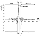
- An output voltage waveform of a detection signal of the vibration sensor unit 10 at the time of tire rotation is, for example, a waveform shown in FIG.
- FIG. 4 the peak value at the start of grounding where the output voltage of the vibration sensor unit 10 has a maximum value is referred to as a first peak value.
- the output voltage of the vibration sensor unit 10 takes a local minimum value at the end of grounding when the device mounting position is not grounded from the state of being grounded as the tire 3 rotates.
- the peak value at the end of grounding where the output voltage of the vibration sensor unit 10 has a local minimum value is referred to as a second peak value.
- the reason why the output voltage of the vibration sensor unit 10 has a peak value at the above timing is as follows. That is, when the device mounting position is in contact with the ground as the tire 3 rotates, a portion of the tire 3 which is a substantially cylindrical surface in the vicinity of the vibration sensor unit 10 is pressed and deformed into a planar shape. By receiving the impact at this time, the output voltage of the vibration sensor unit 10 takes a first peak value. Further, when the device mounting position is separated from the ground contact surface as the tire 3 rotates, the tire 3 is released from the pressure in the vicinity of the vibration sensor unit 10 and returns from the planar shape to the substantially cylindrical shape. By receiving an impact when the shape of the tire 3 returns to the original state, the output voltage of the vibration sensor unit 10 takes a second peak value.
- the output voltage of the vibration sensor unit 10 takes the first and second peak values at the start of grounding and at the end of grounding, respectively. Further, since the direction of the impact when the tire 3 is pressed and the direction of the impact when released from the pressing are opposite, the sign of the output voltage is also the opposite.
- step-in region the moment when the device mounting position comes in contact with the road surface
- kick-out region the moment when the device is separated from the road surface
- the “step-in area” includes the timing at which the first peak value is obtained
- the “kick-out area” includes the timing at which the second peak value is obtained.
- the area before the stepping area is the area before the stepping area, the area from the stepping area to the kicking area, that is, the area where the device mounting position is in contact with the area before the kicking, and the area after the kicking area "
- five areas R1 to R5 are “pre-step-in area”, “step-in area”, “kick-out front area”, “kick-out area”, and “post-kick out area” in the detection signal in this order. It is shown as.
- the vibration generated in the tire 3 fluctuates in each of the divided areas, and the detection signal of the vibration sensor unit 10 changes, so that the frequency analysis of the detection signal of the vibration sensor unit 10 in each area is performed.
- the road surface state can be determined based on the frequency analysis of the detection signal.
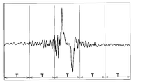
- the waveform processing unit 11a generates a plurality of detection signals of the vibration sensor unit 10 for one rotation of the tire 3 having a continuous time axis waveform, as shown in FIG.
- the feature quantity is extracted by dividing into sections and performing frequency analysis in each section. Specifically, the power spectrum value in each frequency band, that is, the vibration level in the specific frequency band is determined by performing frequency analysis in each section, and this power spectrum value is used as the feature amount.
- the number of the division divided by the time window of time width T is a value which changes according to the rotational speed of the tire 3 in more detail according to the vehicle speed.
- the time width T can be set to a predetermined time, for example, 3 msec, or can be changed according to the vehicle speed.
- the number of sections for one tire rotation is n (where n is a natural number).
- the power obtained by passing the detection signal of each section through five band pass filters of a plurality of specific frequency bands for example, 0 to 1 kHz, 1 to 2 kHz, 2 to 3 kHz, 3 to 4 kHz, or 4 to 5 kHz
- This feature quantity is called a feature vector
- a feature vector Xi of a section i (where i is a natural number of 1 ⁇ i ⁇ n) is represented by aik when the power spectrum value of each specific frequency band is indicated by aik It is expressed as in the following equation as a matrix having.
- This determinant X is an expression representing the feature amount for one rotation of the tire.
- the control unit 11 extracts the feature quantity represented by the determinant X by frequency analysis of the detection signal of the vibration sensor unit 10.
- the feature amount included in the road surface data transmitted from the tire device 1 is compared with the support vector for each road surface type stored in the support vector storage unit 25. Then, the road surface condition is determined. For example, it is possible to determine the degree of similarity with all the support vectors for each type of road surface, and to determine the road surface of the support vector having the highest similarity as the current traveling road surface.
- the calculation of the similarity between the feature amount and all the support vectors for each type of road surface can be performed, for example, by the following method.
- the determinant of the feature is X (r)
- the determinant of the support vector is X (s)
- the power spectrum value a ik serving as each element of each determinant Let be represented by a (r) ik , a (s) ik .
- the determinant X (r) of the feature amount and the determinant X (s) of the support vector are expressed as follows.
- the similarity indicates the degree of similarity between the feature quantities indicated by the two determinants and the support vector, which means that the higher the similarity, the more similar.
- the road surface determination unit 26 obtains the similarity using the kernel method, and determines the road surface state based on the similarity.
- the inner product of the determinant X (r) of the feature amount and the determinant X (s) of the support vector in other words, the feature vector Xi of sections divided by each time window of a predetermined time width T in the feature space The distance between the coordinates indicated by is calculated and used as the similarity.
- the time axis waveform at the time of rotation of the tire 3 and the time axis waveform of the support vector each have a predetermined time width T Divide into each section.
- T time width
- n 5 and i is represented by 1 ⁇ i ⁇ 5.
- the feature vector Xi of each section when the tire 3 is rotating this time is Xi (r)
- the feature vector of each section of the support vector is Xi (s).
- feature vectors are obtained by dividing into five specific frequency bands. Therefore, the feature vector Xi of each section is represented in the six-dimensional space aligned with the time axis, and the distance between the coordinates indicated by the feature vector Xi of the sections is the distance between the coordinates in the six-dimensional space.
- the distance between coordinates indicated by the feature vector of each section is smaller as the feature amount and the support vector are similar and larger as they are not similar, so the smaller the distance is, the higher the similarity is, and the distance is The larger the value, the lower the degree of similarity.
- the distance K yz between coordinates indicated by the feature vector of the compartment between time-division determined for all sections and calculates the distance K yz sum K total of all sections fraction, the sum K total similarity It is used as the corresponding value.
- the total sum K total is compared with a predetermined threshold Th, and it is determined that the degree of similarity is low if the total sum K total is larger than the threshold Th, and the degree of similarity is high if the total K total is smaller than the threshold Th.
- the calculation of the similarity is performed on all the support vectors, and it is determined that the type of the road surface corresponding to the support vector having the highest similarity is the road condition currently being traveled. In this way, road surface condition determination can be performed.
- the sum K total of the distance K yz between two coordinates indicated by the feature vector of each section is used as a value corresponding to the degree of similarity
- another parameter may be used as a parameter indicating the degree of similarity.
- a parameter indicating the degree of similarity an average distance K ave which is an average value of the distances K yz obtained by dividing the total sum K total by the number of sections is used, or a least squares method is used.
- Various kernel functions can also be used to determine the degree of similarity.
- the data selection unit 11b selects feature amount data to be included in the road surface data, and the data selection unit 11b selects data of feature amounts for one rotation of the tire.
- the road surface determination unit 26 There is a case where only a part is transmitted to the road surface determination unit 26. In that case, calculation of the degree of similarity is performed using a part of the feature quantity during one rotation of the tire included in the road surface data and the part corresponding to that of the support vector.
- a method of data selection in the data selection unit 11 b and a method of calculating the degree of similarity based on some of the selected feature amounts will be described.
- the method of data selection will be described. Regarding the selection of data, among the feature quantities obtained from the detection signals of the vibration sensor unit 10 for one rotation of the tire, the one with a high degree of feature that represents the road surface condition is selected. Then, in the case of the present embodiment, the feature amount having the highest feature degree among them is selected.
- the feature degree indicates the rate at which the difference between feature amounts increases according to the type of road surface condition. As the characteristic degree is higher, the difference in the characteristic amount according to the type of road surface state appears larger. Therefore, by judging the road surface state using the characteristic amount with high characteristic degree, the road surface state is discriminated even with a small amount of data. Is possible.
- the feature degree is high in a specific area during one rotation of the tire.
- the output voltage waveform of the detection signal of one rotation of the tire of the vibration sensor unit 10 is as shown in FIG.
- the difference in the feature amount with respect to other types of road surfaces such as the dry road and the frozen road appears in the region R2. This is because on a wet road, the amount of slip that occurs immediately before the device mounting position attempts to touch the road surface is larger than that on other road surfaces.
- the difference in the feature value with respect to other types of road surfaces such as the dry road and the freezing road appears largely. This is because in the freezing road, the device mounting position is most affected by the vibration caused by the slip of the road surface during the grounding.
- the degree of feature is increased in a specific region during one rotation of the tire, depending on the type of road surface.
- the specific region mentioned here typically corresponds to the regions R1 to R5, it may be part of the regions R1 to R5, such as a portion near the region R2 in the region R1. A plurality of regions may be straddled as in the region R2 and the region R3.
- a specific area can be grasped as one or more of each section obtained by dividing the detection signal by the time width T, the detection signal in one rotation of the tire is in agreement with the detection signal in a predetermined timing or a predetermined period. is there.
- the feature degree is high in a specific frequency band.
- this vibration component may not directly represent the road condition.
- this vibration component appears in a frequency band of, for example, several hundreds Hz, so that a characteristic amount according to the road surface condition which is to be truly discriminated in a frequency band different from this frequency band is obtained. Become.
- a feature amount of a specific area is selected from feature amounts obtained from detection signals for one rotation of the tire in the vibration sensor unit 10, or a feature amount of a specific frequency band is selected. be able to. Further, it is possible to select a feature amount that is a specific region and a specific frequency band from the feature amounts obtained from the detection signal of one rotation of the tire in the vibration sensor unit 10.
- the feature amounts of the region R2 and the region R3 are selected from the feature amounts obtained from the detection signal of one rotation of the tire in the vibration sensor unit 10.
- the feature amount in the frame C1 surrounded by the alternate long and short dash line in the formula is selected.
- the feature quantities of the frequency band of 1 kHz or more excluding the frequency band of several hundreds Hz are selected from the feature quantities obtained from the detection signal of one rotation of the tire in the vibration sensor unit 10.
- a frequency band of 1 to 2 kHz can be selected, and in this case, as shown in Formula 7, the feature value in the frame C2 surrounded by a dashed dotted line in the formula is selected.
- the feature within a frame C3 surrounded by an alternate long and short dash line in the equation is selected as shown in Equation 8.
- the region selected by data selection and the frequency band of the feature amount may differ depending on vehicle specifications and the like, or may differ depending on the type of tire 3 and the like. Therefore, the feature degree may be obtained based on an experiment or the like, and data selection may be performed using a region or a frequency band in which the feature degree particularly increases.
- the road surface determination unit 26 calculates the degree of similarity using a part of the feature quantity during one rotation of the tire included in the road surface data and the part corresponding to that of the support vector.
- region by data selection was demonstrated here.
- the method of calculating the degree of similarity is the same as in the case of selecting a feature of a specific frequency band or in the case of selecting a feature of a specific region and a specific frequency band.
- a portion corresponding to the frame C2 is extracted from the feature amount of the frame C2 in Equation 7 and all the support vectors for each type of road surface, and the distance is calculated to be a value corresponding to the similarity. be able to.
- control unit 11 In the tire side device 1, the control unit 11 is in the sleep state when it is not the transmission timing of the road surface data, but it automatically switches to the wakeup state at every transmission timing of the road surface data. Run.
- step S100 the control unit 11 causes the waveform processing unit 11a to acquire the time axis waveform of the detection signal of one rotation of the tire in the vibration sensor unit 10. Then, the process proceeds to step S110, and the acquired detection signal of the time axis waveform is divided into a plurality of sections for each time window of a predetermined time width T. Thereafter, the process proceeds to step S120, where frequency analysis is performed on each section divided in step S110, and power spectrum values in each frequency band are obtained to calculate a feature amount for one rotation of the tire.
- step S130 the data selection unit 11b selects a feature amount having the highest feature degree from among the feature amounts for one rotation of the tire calculated in step S120. For example, as described above, the feature amount of a specific region or a specific frequency band is selected, or a feature amount that is a specific region and a specific frequency is selected. Then, in step S140, the data selection unit 11b transmits road surface data including the selected feature amount to the data communication unit 12. Accordingly, road surface data including the selected feature amount is transmitted to the vehicle body side system 2 through the data communication unit 12.
- the road surface determination unit 26 executes the road surface condition determination process shown in FIG. 9 every predetermined control cycle. This process is executed each time road surface data is sent from each tire side device 1.
- step S200 the road surface determination unit 26 performs data reception processing. This process is performed by receiving the road surface data transmitted from each tire side device 1 through the data communication unit 24. In the case where the road surface data is transmitted from the tire side device 1 in step S140 of FIG. 8, the data communication portion 24 receives the road surface data.
- step S210 determines the road surface state.
- the determination of the road surface state is performed using the calculation method of the similarity based on the selected partial feature amount.
- step S220 it is determined whether it is possible to determine the road surface state. That is, when the road surface state is determined using the similarity calculation method based on the selected partial feature amount, the road surface state can be determined at a high rate, but the road surface state is not necessarily determined for all situations. It can not be determined.
- the road surface condition on the road surface on which the vehicle is traveling changes from a dry road to a wet road, or from a wet road to a frozen road, but the road surface state changes gradually rather than abruptly. In some cases. During the change, it may not be possible to clearly determine the road surface condition.
- step S230 the determination result of the road surface state is transmitted to the notification device 23 and the brake ECU 22 to end the process, and when the determination is not performed, the process proceeds to step S240.
- step S240 the data communication unit 24 transmits instruction data requesting transmission of more detailed road surface data to the tire-side device 1 that has sent the road surface data.
- each tire-side device 1 After transmitting the road surface data including the feature quantities of a part during one rotation of the tire, each tire-side device 1 proceeds to step S150 and enters a data standby state. That is, as described above, when the road surface determination unit 26 can not determine the road surface state, instruction data is sent in step S240 of FIG. For this reason, each tire side device 1 will be in the waiting state of the indication data which may be sent.
- the data standby state is continued until the predetermined time elapses in step S170, and when the instruction data is received during the predetermined time, the process proceeds to step S180. Thereafter, processing is performed to transmit road surface data including all feature quantities for one rotation of the tire so that road surface state determination based on more detailed road surface data can be performed this time.
- step S180 road surface data including all the feature values for one rotation of the tire is transmitted through the data communication unit 12. Then, if the instruction data does not arrive even after the predetermined time has passed in step S170, or if more detailed road surface data transmission is performed in step S180, the process proceeds to step S190, and the road surface determination unit 26 enters the sleep state. End the process.
- road surface data including all feature amounts for one rotation of the tire is transmitted here, some of the feature amounts with high feature rates have already been transmitted to the road surface determination unit 26, so the rest is Road surface data may be transmitted including only the feature amounts of. By doing so, it is possible to shorten the transmission time of road surface data.
- step S240 after the instruction data is transmitted in step S240, more detailed road surface data is sent from the tire side device 1, so the process proceeds to step S250 to perform data reception processing.
- the road surface determination unit 26 receives more detailed road surface data, it determines the road surface state based on the more detailed road surface data in step S260. That is, the feature amount for one rotation of the tire is obtained as to the degree of similarity with all the support vectors for each type of road surface, and the road surface of the support vector with the highest similarity is determined as the current traveling road surface. Then, when the road surface state is determined in this manner, the process proceeds to step S230, the determination result of the road surface state is transmitted to the notification device 23 and the brake ECU 22, and the process is ended.
- the tire system 100 can determine the road surface state of the traveling road surface of the vehicle. Then, normally, road surface data including a feature amount of a part during one rotation of the tire is transmitted from each tire side device 1, and the road surface state is determined by the vehicle body side system 2 based on the road surface data. For this reason, it becomes possible to shorten the transmission time when transmitting data from the tire side device 1. Therefore, the road surface state determination can be performed with high responsiveness, and the vehicle motion control with high responsiveness can be performed. Furthermore, power consumption for data transmission can be reduced, and battery life can be improved.
- the road surface condition is constant over a long period of time, and the rate at which the road surface condition changes is small compared with that.
- the characteristics of the tire G are obviously different in each road surface condition such as dry road surface, set road surface, snow road surface and frozen road surface, and road surface data including a part of feature values during one rotation of the tire at high rate only
- the road surface condition can be determined based on From this, it is possible to shorten the transmission time of the road surface data at a high rate while the vehicle is traveling, and to obtain the effect that the power consumption can be reduced.
- the instruction data is transmitted from the vehicle body side system 2 to the tire side device 1 To be done.
- the instruction data is transmitted from the vehicle body side system 2 to the tire side device 1. Therefore, more detailed road surface data can be transmitted from the tire side device 1, and the road surface determination unit 26 can reliably determine the road surface state.
- road surface data including all feature amounts for one tire rotation is transmitted in step S180 of FIG. 8, but all feature amounts for one tire rotation are necessarily included from the beginning There is no need to transmit road surface data.
- the feature degree is the second highest. Make it possible to transmit road surface data including quantity. Then, when the road surface determination unit 26 still can not determine the road surface state, it is possible to transmit road surface data including all feature amounts for one rotation of the tire.
- the tire side device 1 transmits road surface data including at least a part of a feature different from the one already transmitted as the feature included in the road data, and if the road surface condition can not be determined, Transmit road surface data including at least a part.
- the road surface condition may be determined by changing the feature amount to be transmitted stepwise.
- the data selection is performed by specifying the condition of the feature amount to be selected from the feature amount for one rotation of the tire. For example, the feature amount of a specific region is selected, or the feature amount of a specific frequency band is selected. This condition may be varied based on the instruction data from the vehicle body side system 2. For example, from the vehicle body side system 2, selection of a feature amount of a specific area may be instructed by instruction data, or selection of a feature amount of a specific frequency may be instructed by instruction data.
- the road surface condition is determined based on the road surface data including the feature value of the region R2. Is preferred.
- the road surface data including the feature value of the specific frequency band for example, the band of 1 to 2 kHz It is preferable to determine the road surface condition based on the above. Therefore, the instruction data may also be instructed from the vehicle body side system 2 to the tire side device 1 to transmit road surface data including a feature amount having a high degree of characteristic in the road surface state when the road surface state is a specific one. it can.
- the vibration sensor unit 10 can also be configured by an element capable of performing other vibration detection, for example, a piezoelectric element. .
- data including a feature amount is used as road surface data indicating a road surface condition appearing in the detection signal of the vibration sensor unit 10 from the tire side device 1.
- road surface data indicating a road surface condition appearing in the detection signal of the vibration sensor unit 10 from the tire side device 1.
- other data may be used as road surface data.
- integrated value data of vibration waveforms of five regions R1 to R5 included in vibration data during one rotation of the tire 3 may be used as road surface data
- raw data of the detection signal itself may be used as road surface data (5)
- the road surface state is determined by obtaining the similarity between the feature amount and the support vector by the road surface determination unit 26 of the receiver 21 provided in the vehicle body side system 2.
- another ECU such as the brake ECU 22 or the like determines the degree of similarity, determines the road surface state, or performs an instruction signal detection at any place of the vehicle body side system 2. Transmission may be performed. Further, the support vector is stored in the tire side device 1 so that the road surface state can be determined by the tire side device 1, and data indicating the determination result of the road surface state is sent to the vehicle body side system 2 as road surface data. It is good.
Landscapes
- Engineering & Computer Science (AREA)
- Physics & Mathematics (AREA)
- General Physics & Mathematics (AREA)
- Mechanical Engineering (AREA)
- Environmental & Geological Engineering (AREA)
- Life Sciences & Earth Sciences (AREA)
- Atmospheric Sciences (AREA)
- Biodiversity & Conservation Biology (AREA)
- Ecology (AREA)
- Environmental Sciences (AREA)
- Tires In General (AREA)
Priority Applications (1)
| Application Number | Priority Date | Filing Date | Title |
|---|---|---|---|
| US16/910,778 US11467028B2 (en) | 2017-12-28 | 2020-06-24 | Road surface state determination device |
Applications Claiming Priority (2)
| Application Number | Priority Date | Filing Date | Title |
|---|---|---|---|
| JP2017-254282 | 2017-12-28 | ||
| JP2017254282A JP6791114B2 (ja) | 2017-12-28 | 2017-12-28 | 路面状態判別装置 |
Related Child Applications (1)
| Application Number | Title | Priority Date | Filing Date |
|---|---|---|---|
| US16/910,778 Continuation US11467028B2 (en) | 2017-12-28 | 2020-06-24 | Road surface state determination device |
Publications (1)
| Publication Number | Publication Date |
|---|---|
| WO2019131567A1 true WO2019131567A1 (ja) | 2019-07-04 |
Family
ID=67067413
Family Applications (1)
| Application Number | Title | Priority Date | Filing Date |
|---|---|---|---|
| PCT/JP2018/047408 Ceased WO2019131567A1 (ja) | 2017-12-28 | 2018-12-24 | 路面状態判別装置 |
Country Status (3)
| Country | Link |
|---|---|
| US (1) | US11467028B2 (enExample) |
| JP (1) | JP6791114B2 (enExample) |
| WO (1) | WO2019131567A1 (enExample) |
Cited By (1)
| Publication number | Priority date | Publication date | Assignee | Title |
|---|---|---|---|---|
| US11565705B2 (en) | 2017-12-22 | 2023-01-31 | Denso Corporation | Road surface state determination device |
Families Citing this family (2)
| Publication number | Priority date | Publication date | Assignee | Title |
|---|---|---|---|---|
| JP7047466B2 (ja) * | 2018-03-02 | 2022-04-05 | 株式会社Soken | 路面状態判別装置 |
| JP7493840B2 (ja) * | 2020-12-10 | 2024-06-03 | 国立研究開発法人産業技術総合研究所 | 情報処理装置、情報処理方法および制御プログラム |
Citations (5)
| Publication number | Priority date | Publication date | Assignee | Title |
|---|---|---|---|---|
| WO2006135090A1 (ja) * | 2005-06-17 | 2006-12-21 | Kabushiki Kaisha Bridgestone | 路面状態推定方法、路面状態推定用タイヤ、路面状態推定装置、及び、車両制御装置 |
| US20070050121A1 (en) * | 2004-04-02 | 2007-03-01 | Dieter Ammon | Method for determining a coefficient of friction |
| JP2014035279A (ja) * | 2012-08-09 | 2014-02-24 | Bridgestone Corp | 路面状態判別方法とその装置 |
| JP2015174638A (ja) * | 2014-03-18 | 2015-10-05 | 株式会社日本自動車部品総合研究所 | 路面状況推定装置 |
| JP2017198507A (ja) * | 2016-04-26 | 2017-11-02 | 株式会社デンソー | 路面状態検出装置 |
Family Cites Families (6)
| Publication number | Priority date | Publication date | Assignee | Title |
|---|---|---|---|---|
| JP6392623B2 (ja) * | 2014-10-06 | 2018-09-19 | 株式会社ブリヂストン | 路面状態判別システム |
| JP6450170B2 (ja) * | 2014-12-05 | 2019-01-09 | 株式会社ブリヂストン | 路面状態判別方法 |
| JP6614073B2 (ja) * | 2016-09-06 | 2019-12-04 | 株式会社デンソー | 路面状態推定装置 |
| WO2019131568A1 (ja) * | 2017-12-27 | 2019-07-04 | 株式会社デンソー | 路面状態判別装置 |
| JP6777103B2 (ja) | 2018-01-19 | 2020-10-28 | 株式会社Soken | 路面状態判別装置およびそれを含むタイヤシステム |
| JP7047466B2 (ja) | 2018-03-02 | 2022-04-05 | 株式会社Soken | 路面状態判別装置 |
-
2017
- 2017-12-28 JP JP2017254282A patent/JP6791114B2/ja active Active
-
2018
- 2018-12-24 WO PCT/JP2018/047408 patent/WO2019131567A1/ja not_active Ceased
-
2020
- 2020-06-24 US US16/910,778 patent/US11467028B2/en active Active
Patent Citations (5)
| Publication number | Priority date | Publication date | Assignee | Title |
|---|---|---|---|---|
| US20070050121A1 (en) * | 2004-04-02 | 2007-03-01 | Dieter Ammon | Method for determining a coefficient of friction |
| WO2006135090A1 (ja) * | 2005-06-17 | 2006-12-21 | Kabushiki Kaisha Bridgestone | 路面状態推定方法、路面状態推定用タイヤ、路面状態推定装置、及び、車両制御装置 |
| JP2014035279A (ja) * | 2012-08-09 | 2014-02-24 | Bridgestone Corp | 路面状態判別方法とその装置 |
| JP2015174638A (ja) * | 2014-03-18 | 2015-10-05 | 株式会社日本自動車部品総合研究所 | 路面状況推定装置 |
| JP2017198507A (ja) * | 2016-04-26 | 2017-11-02 | 株式会社デンソー | 路面状態検出装置 |
Cited By (1)
| Publication number | Priority date | Publication date | Assignee | Title |
|---|---|---|---|---|
| US11565705B2 (en) | 2017-12-22 | 2023-01-31 | Denso Corporation | Road surface state determination device |
Also Published As
| Publication number | Publication date |
|---|---|
| JP2019120550A (ja) | 2019-07-22 |
| US11467028B2 (en) | 2022-10-11 |
| US20200319020A1 (en) | 2020-10-08 |
| JP6791114B2 (ja) | 2020-11-25 |
Similar Documents
| Publication | Publication Date | Title |
|---|---|---|
| JP6777103B2 (ja) | 路面状態判別装置およびそれを含むタイヤシステム | |
| JP6969399B2 (ja) | タイヤシステム | |
| JP6614073B2 (ja) | 路面状態推定装置 | |
| JP6930355B2 (ja) | 路面状態判別装置およびそれを備えたタイヤシステム | |
| CN110603180B (zh) | 轮胎侧装置及包含其的轮胎装置 | |
| WO2019124482A1 (ja) | 路面状態判別装置 | |
| JP7047466B2 (ja) | 路面状態判別装置 | |
| JP2019127253A (ja) | タイヤシステム | |
| WO2019103095A1 (ja) | 路面状態判別装置 | |
| JP6828716B2 (ja) | 路面状態推定装置 | |
| JP7070155B2 (ja) | 路面状態判別装置およびそれを備えるタイヤシステム | |
| JP2018009974A (ja) | タイヤマウントセンサおよびそれを含む路面状態推定装置 | |
| WO2019131568A1 (ja) | 路面状態判別装置 | |
| JP2019132770A (ja) | 路面状態判別装置 | |
| JP2021037884A (ja) | タイヤ側装置およびそれを含む路面状態判別装置 | |
| JP2019120550A (ja) | 路面状態判別装置 | |
| WO2019103094A1 (ja) | 路面状態判別装置 | |
| JP2019089532A (ja) | 路面状態判別装置 | |
| WO2019142870A1 (ja) | タイヤシステム | |
| WO2019088023A1 (ja) | 路面状態推定装置 | |
| JP2019117181A (ja) | 路面状態判別装置 | |
| WO2019093437A1 (ja) | 路面状態判別装置 |
Legal Events
| Date | Code | Title | Description |
|---|---|---|---|
| 121 | Ep: the epo has been informed by wipo that ep was designated in this application |
Ref document number: 18894242 Country of ref document: EP Kind code of ref document: A1 |
|
| NENP | Non-entry into the national phase |
Ref country code: DE |
|
| 122 | Ep: pct application non-entry in european phase |
Ref document number: 18894242 Country of ref document: EP Kind code of ref document: A1 |