WO2019130961A1 - 血圧測定装置 - Google Patents
血圧測定装置 Download PDFInfo
- Publication number
- WO2019130961A1 WO2019130961A1 PCT/JP2018/043759 JP2018043759W WO2019130961A1 WO 2019130961 A1 WO2019130961 A1 WO 2019130961A1 JP 2018043759 W JP2018043759 W JP 2018043759W WO 2019130961 A1 WO2019130961 A1 WO 2019130961A1
- Authority
- WO
- WIPO (PCT)
- Prior art keywords
- cuff
- blood pressure
- pressure measurement
- living body
- measurement device
- Prior art date
- Legal status (The legal status is an assumption and is not a legal conclusion. Google has not performed a legal analysis and makes no representation as to the accuracy of the status listed.)
- Ceased
Links
Images


Classifications
-
- A—HUMAN NECESSITIES
- A61—MEDICAL OR VETERINARY SCIENCE; HYGIENE
- A61B—DIAGNOSIS; SURGERY; IDENTIFICATION
- A61B5/00—Measuring for diagnostic purposes; Identification of persons
- A61B5/02—Detecting, measuring or recording for evaluating the cardiovascular system, e.g. pulse, heart rate, blood pressure or blood flow
- A61B5/021—Measuring pressure in heart or blood vessels
- A61B5/022—Measuring pressure in heart or blood vessels by applying pressure to close blood vessels, e.g. against the skin; Ophthalmodynamometers
- A61B5/02233—Occluders specially adapted therefor
-
- A—HUMAN NECESSITIES
- A61—MEDICAL OR VETERINARY SCIENCE; HYGIENE
- A61B—DIAGNOSIS; SURGERY; IDENTIFICATION
- A61B5/00—Measuring for diagnostic purposes; Identification of persons
- A61B5/02—Detecting, measuring or recording for evaluating the cardiovascular system, e.g. pulse, heart rate, blood pressure or blood flow
- A61B5/0205—Simultaneously evaluating both cardiovascular conditions and different types of body conditions, e.g. heart and respiratory condition
-
- A—HUMAN NECESSITIES
- A61—MEDICAL OR VETERINARY SCIENCE; HYGIENE
- A61B—DIAGNOSIS; SURGERY; IDENTIFICATION
- A61B5/00—Measuring for diagnostic purposes; Identification of persons
- A61B5/02—Detecting, measuring or recording for evaluating the cardiovascular system, e.g. pulse, heart rate, blood pressure or blood flow
- A61B5/021—Measuring pressure in heart or blood vessels
- A61B5/02141—Details of apparatus construction, e.g. pump units or housings therefor, cuff pressurising systems, arrangements of fluid conduits or circuits
-
- A—HUMAN NECESSITIES
- A61—MEDICAL OR VETERINARY SCIENCE; HYGIENE
- A61B—DIAGNOSIS; SURGERY; IDENTIFICATION
- A61B5/00—Measuring for diagnostic purposes; Identification of persons
- A61B5/02—Detecting, measuring or recording for evaluating the cardiovascular system, e.g. pulse, heart rate, blood pressure or blood flow
- A61B5/021—Measuring pressure in heart or blood vessels
- A61B5/022—Measuring pressure in heart or blood vessels by applying pressure to close blood vessels, e.g. against the skin; Ophthalmodynamometers
- A61B5/02225—Measuring pressure in heart or blood vessels by applying pressure to close blood vessels, e.g. against the skin; Ophthalmodynamometers using the oscillometric method
-
- A—HUMAN NECESSITIES
- A61—MEDICAL OR VETERINARY SCIENCE; HYGIENE
- A61B—DIAGNOSIS; SURGERY; IDENTIFICATION
- A61B5/00—Measuring for diagnostic purposes; Identification of persons
- A61B5/02—Detecting, measuring or recording for evaluating the cardiovascular system, e.g. pulse, heart rate, blood pressure or blood flow
- A61B5/021—Measuring pressure in heart or blood vessels
- A61B5/022—Measuring pressure in heart or blood vessels by applying pressure to close blood vessels, e.g. against the skin; Ophthalmodynamometers
- A61B5/0235—Valves specially adapted therefor
-
- A—HUMAN NECESSITIES
- A61—MEDICAL OR VETERINARY SCIENCE; HYGIENE
- A61B—DIAGNOSIS; SURGERY; IDENTIFICATION
- A61B5/00—Measuring for diagnostic purposes; Identification of persons
- A61B5/68—Arrangements of detecting, measuring or recording means, e.g. sensors, in relation to patient
- A61B5/6801—Arrangements of detecting, measuring or recording means, e.g. sensors, in relation to patient specially adapted to be attached to or worn on the body surface
- A61B5/6802—Sensor mounted on worn items
- A61B5/681—Wristwatch-type devices
-
- A—HUMAN NECESSITIES
- A61—MEDICAL OR VETERINARY SCIENCE; HYGIENE
- A61B—DIAGNOSIS; SURGERY; IDENTIFICATION
- A61B5/00—Measuring for diagnostic purposes; Identification of persons
- A61B5/68—Arrangements of detecting, measuring or recording means, e.g. sensors, in relation to patient
- A61B5/6801—Arrangements of detecting, measuring or recording means, e.g. sensors, in relation to patient specially adapted to be attached to or worn on the body surface
- A61B5/6813—Specially adapted to be attached to a specific body part
- A61B5/6824—Arm or wrist
-
- A—HUMAN NECESSITIES
- A61—MEDICAL OR VETERINARY SCIENCE; HYGIENE
- A61B—DIAGNOSIS; SURGERY; IDENTIFICATION
- A61B5/00—Measuring for diagnostic purposes; Identification of persons
- A61B5/68—Arrangements of detecting, measuring or recording means, e.g. sensors, in relation to patient
- A61B5/6801—Arrangements of detecting, measuring or recording means, e.g. sensors, in relation to patient specially adapted to be attached to or worn on the body surface
- A61B5/683—Means for maintaining contact with the body
- A61B5/6831—Straps, bands or harnesses
-
- A—HUMAN NECESSITIES
- A61—MEDICAL OR VETERINARY SCIENCE; HYGIENE
- A61B—DIAGNOSIS; SURGERY; IDENTIFICATION
- A61B5/00—Measuring for diagnostic purposes; Identification of persons
- A61B5/74—Details of notification to user or communication with user or patient; User input means
- A61B5/742—Details of notification to user or communication with user or patient; User input means using visual displays
-
- G—PHYSICS
- G04—HOROLOGY
- G04G—ELECTRONIC TIME-PIECES
- G04G21/00—Input or output devices integrated in time-pieces
- G04G21/02—Detectors of external physical values, e.g. temperature
- G04G21/025—Detectors of external physical values, e.g. temperature for measuring physiological data
-
- A—HUMAN NECESSITIES
- A61—MEDICAL OR VETERINARY SCIENCE; HYGIENE
- A61B—DIAGNOSIS; SURGERY; IDENTIFICATION
- A61B2562/00—Details of sensors; Constructional details of sensor housings or probes; Accessories for sensors
- A61B2562/02—Details of sensors specially adapted for in-vivo measurements
- A61B2562/0219—Inertial sensors, e.g. accelerometers, gyroscopes, tilt switches
-
- A—HUMAN NECESSITIES
- A61—MEDICAL OR VETERINARY SCIENCE; HYGIENE
- A61B—DIAGNOSIS; SURGERY; IDENTIFICATION
- A61B2562/00—Details of sensors; Constructional details of sensor housings or probes; Accessories for sensors
- A61B2562/02—Details of sensors specially adapted for in-vivo measurements
- A61B2562/0247—Pressure sensors
-
- A—HUMAN NECESSITIES
- A61—MEDICAL OR VETERINARY SCIENCE; HYGIENE
- A61B—DIAGNOSIS; SURGERY; IDENTIFICATION
- A61B5/00—Measuring for diagnostic purposes; Identification of persons
- A61B5/103—Measuring devices for testing the shape, pattern, colour, size or movement of the body or parts thereof, for diagnostic purposes
- A61B5/11—Measuring movement of the entire body or parts thereof, e.g. head or hand tremor or mobility of a limb
- A61B5/1118—Determining activity level
-
- A—HUMAN NECESSITIES
- A61—MEDICAL OR VETERINARY SCIENCE; HYGIENE
- A61B—DIAGNOSIS; SURGERY; IDENTIFICATION
- A61B5/00—Measuring for diagnostic purposes; Identification of persons
- A61B5/74—Details of notification to user or communication with user or patient; User input means
- A61B5/7475—User input or interface means, e.g. keyboard, pointing device, joystick
Definitions
- the present invention relates to a blood pressure measurement device that measures blood pressure.
- a blood pressure measurement device used to measure blood pressure is used not only in medical facilities but also in the home as a means for confirming the health condition.
- the blood pressure measurement device measures the blood pressure by detecting the vibration of the arterial wall by, for example, winding the cuff around the upper arm or the wrist of a living body, inflating and deflating the cuff, and detecting the pressure of the cuff with a pressure sensor.
- wrinkles in the cuff may cause division of the inner space of the cuff or loss of inflation pressure, which may reduce the accuracy of measurement of blood pressure, resulting in uneven measurement results. causes the blood pressure measurement results to be affected.
- a cuff for a blood pressure measurement device that suppresses the occurrence of wrinkles in the bag-like cover body.
- the cuff for a blood pressure measurement device includes a portion having a large curvature and a portion having a small curvature in the winding direction so that the curler contained in the bag-like cover body into which the air bag is inserted fits the non-measurement portion. .
- the inner cover member of the portion corresponding to the portion with the large curvature of the curler is pulled in the width direction, and wrinkles are suppressed.
- the cuff for a blood pressure measurement device is configured, for example, to change the suture interval in the width direction of the inner cover member and the outer cover member of the portion of the bag-like cover body corresponding to the portion having a large curvature of the curler
- the cuff is a configuration other than a cuff for a blood pressure measurement device in which the air bag and the curler are inserted into the above-described bag-like cover body, the cuff supplied with the fluid comes in contact with the living body, and a plurality of air bags Also known is a configuration in which the layers are stacked. There is a need for a technique that can suppress the occurrence of wrinkles that affect blood pressure measurement results in such various cuffs.
- an object of this invention is to provide the blood pressure measurement apparatus which can suppress generation
- a bag-like cuff which is wound around a living body and is expanded by supplying fluid to the internal space, a supply device for supplying the fluid into the cuff, and the living body side of the cuff
- a blood pressure measuring device comprising: a guiding unit that causes the living body side of the cuff to crease in the direction of winding of the cuff when the cuff is inflated to compress the living body; .
- the fluid includes liquid and air.
- the heel is a bag-like cuff expanded in a state of being wound around a living body, and when a circumferential difference (inner / outer circumferential difference) occurs between the outer circumferential surface and the inner circumferential surface of the cuff, It is a fold which arises in the inner skin of a cuff so that one part may be located in the outer skin side.
- the cuff is wound around the upper arm or the wrist of a living body when blood pressure is measured, and is expanded by supplying a fluid.
- a pressure cuff provided in a blood pressure measurement device that measures the blood pressure at the wrist It includes a sensing cuff and a cuff provided to a blood pressure measurement device that measures blood pressure with the upper arm.
- the cuff here may be a bag-like structure such as an air bag that constitutes the pressing cuff.
- the supply device is a device main body of a blood pressure measurement device including a pump and a flow path.
- the guide portion when the cuff is wound around a living body and expanded, the guide portion generates a wrinkle generated on the inner peripheral surface side due to the inner and outer circumferential difference, thereby managing the wrinkle generation location and the wrinkle depth. be able to.
- the pressure sore on the inner circumferential surface of the cuff may be divided or the pressure may fluctuate when the cuff presses the living body, and the accuracy of the measured blood pressure value
- the blood pressure measurement results may be affected, such as being lowered.
- the position of the wrinkles generated on the inner circumferential surface of the cuff can be managed, and therefore, it occurs on the inner circumferential surface side of the cuff when the cuff is inflated due to individual differences in living bodies and differences in cuff usage conditions. It is possible to suppress the variation in the position and depth of the brow.
- the blood pressure measurement device can stably press the living body by the cuff, so that it is possible to prevent the occurrence of variation in the measured blood pressure value and improve the accuracy of the blood pressure measurement result.
- the blood pressure measurement device is provided, wherein the guide portion is a plurality of grooves provided on the outer surface of the cuff.
- the guide portion as a groove, it is possible to manage wrinkles with a simple configuration without increasing the thickness of the cuff.
- the guide portion is provided so as to avoid the position of the cuff facing the artery of the living body.
- the guiding portion is provided to avoid the position of the cuff facing the artery of the living body, so that the occurrence of wrinkles can be suppressed at the position facing the artery of the cuff, and Even if wrinkles occur when the cuff is inflated, the wrinkles may be shallower than the wrinkles produced by the guide.
- the blood pressure measurement device is provided in which a plurality of the guide portions are provided at equal intervals.
- the plurality of wrinkles can be generated at equal intervals on the inner circumferential surface side of the cuff, so that the depth of the wrinkles can be made the same depth, so that it is possible to suppress partial deep wrinkles from being generated. .
- the blood pressure measurement device in which the guiding unit causes wrinkles in a direction orthogonal to the winding direction of the cuff.
- a back plate provided on the living body side of the cuff and extending in a circumferential direction of the wrist of the living body, and provided on the living body side of the back plate, the cuff
- a sac-like sensing cuff which is provided in a region where the artery of the wrist is present and is expanded by supplying fluid to the internal space when it is wound;
- a pump for supplying fluid to the cuff and the sensing cuff;
- a blood pressure measurement device comprising: a device main body that accommodates the pump; and a belt provided in the device main body and mounted along the circumferential direction of the wrist.
- the measurement site is a region where an artery of a living body exists, and is a site where blood pressure can be measured, and examples thereof include a wrist, an upper arm, an ankle, and the like.
- the blood pressure detection device can prevent variations in blood pressure values due to hemorrhoids, so that the accuracy of blood pressure measurement results can be improved.
- the present invention can provide a blood pressure measurement device capable of improving the accuracy of blood pressure measurement results by suppressing the occurrence of pressure sores.
- FIG. 1 is a perspective view showing a configuration of a blood pressure measurement device according to a first embodiment of the present invention.
- FIG. 2 is a perspective view showing the configuration of the blood pressure measurement device.
- FIG. 3 is an exploded view showing a configuration of the blood pressure measurement device.
- FIG. 4 is a block diagram showing the configuration of the blood pressure measurement device.
- FIG. 5 is a perspective view showing another configuration of the blood pressure measurement device.
- FIG. 6 is a perspective view showing the configuration of the device main body of the blood pressure measurement device.
- FIG. 7 is a plan view showing an internal configuration of the apparatus main body.
- FIG. 8 is a plan view showing an internal configuration of the apparatus main body.
- FIG. 9 is a plan view showing the configuration of the cuff structure of the blood pressure measurement device.
- FIG. 1 is a perspective view showing a configuration of a blood pressure measurement device according to a first embodiment of the present invention.
- FIG. 2 is a perspective view showing the configuration of the blood pressure measurement device.
- FIG. 10 is a cross-sectional view showing the configuration of the curler and cuff structure of the blood pressure measurement device.
- FIG. 11 is a cross-sectional view showing the structure of the curler and the cuff structure.
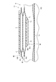
- FIG. 12 is a side view schematically showing the configuration of the pressure cuff of the cuff structure when inflated.
- FIG. 13 is sectional drawing which shows typically the structure at the time of expansion of the pressure cuff of the cuff structure.
- FIG. 14 is a flow chart showing an example of use of the same blood pressure measurement device.
- FIG. 15 is a perspective view showing an example of wearing the blood pressure measurement device on the wrist.
- FIG. 16 is a perspective view showing an example of wearing the blood pressure measurement device on the wrist.
- FIG. 15 is a perspective view showing an example of wearing the blood pressure measurement device on the wrist.
- FIG. 17 is a perspective view showing an example of wearing the blood pressure measurement device on the wrist.
- FIG. 18 is a plan view showing the configuration of a cuff structure according to a second embodiment of the present invention.
- FIG. 19 is a side view schematically showing the configuration of the pressure cuff of the cuff structure when inflated.
- FIG. 20 is a plan view showing the configuration of a cuff structure according to a third embodiment of the present invention.
- FIG. 21 is a side view schematically showing the configuration of the pressure cuff of the cuff structure when inflated.
- FIG. 22 is a perspective view showing a configuration of a blood pressure measurement device according to a fourth embodiment of the present invention.
- FIG. 23 is a cross-sectional view showing the configuration of the blood pressure measurement device.
- FIG. 24 is a block diagram showing the configuration of the blood pressure measurement device.
- FIGS. 1 to 12 An example of the blood pressure measurement device 1 according to the first embodiment of the present invention will be illustrated below using FIGS. 1 to 12.
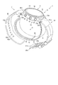
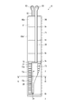
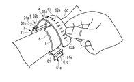
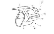
- FIG. 1 is a perspective view showing a configuration of a blood pressure measurement device 1 according to a first embodiment of the present invention in a state in which a belt 4 is closed.
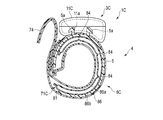
- FIG. 2 is a perspective view showing the configuration of the blood pressure measurement device 1 with the belt 4 opened.
- FIG. 3 is an exploded view showing the configuration of the blood pressure measurement device 1.
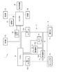
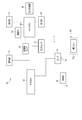
- FIG. 4 is a block diagram showing the configuration of the blood pressure measurement device 1.
- FIG. 5 is a perspective view showing another configuration of the blood pressure measurement device 1.
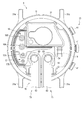
- FIG. 6 is a perspective view showing the configuration of the device body 3 of the blood pressure measurement device 1 from the back cover 35 side.
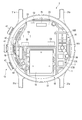
- 7 and 8 are plan views showing the internal configuration of the device body 3 from the side of the windshield 32 and the side of the back cover 35, respectively.
- FIG. 9 is a plan view showing the configuration of the cuff structure 6 of the blood pressure measurement device 1 from the sensing cuff 73 side.
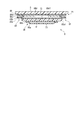
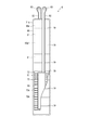
- FIG. 10 is a cross-sectional view schematically showing the configuration of the curler 5 and the cuff structure 6 of the blood pressure measurement device 1 in a cross section along line XX in FIG.
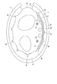
- FIG. 11 is a cross-sectional view showing the configuration of the curler 5 and the cuff structure 6 in a cross section taken along line XI-XI in FIG.
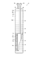
- FIG. 12 and FIG. 13 are views schematically showing an example when the pressure cuff 71 and the sensing cuff 73 of the cuff structure 6 are expanded in side view and cross section.
- the curlers 5 and the cuff structure 6 are schematically shown in a linear shape for convenience of explanation, but in the configuration provided in the blood pressure measurement device 1, they have a curved shape.
- the blood pressure measurement device 1 is an electronic blood pressure measurement device mounted on a living body. The present embodiment will be described using an electronic blood pressure measurement device having an aspect of a wearable device attached to the wrist 100 of a living body. As shown in FIGS. 1 to 12, the blood pressure measurement device 1 includes a device body 3, a belt 4, a curler 5, a cuff structure 6 having a pressure cuff 71 and a sensing cuff 73, and a fluid circuit 7. Have.
- the pressure cuff 71 is an example of the "cuff" of the present invention.
- the device body 3 includes a case 11, a display unit 12, an operation unit 13, a pump 14, a flow passage unit 15, an on-off valve 16, a pressure sensor 17, and electric power.
- a supply unit 18, a vibration motor 19, and a control board 20 are provided.
- the device body 3 is a supply device for supplying a fluid to the pressing cuff 71 by the pump 14, the open / close valve 16, the pressure sensor 17, the control substrate 20 and the like.
- the case 11 includes an outer case 31, a windshield 32 covering the upper opening of the outer case 31, a base 33 provided below the inside of the outer case 31, and a flow path cover 34 covering a part of the back of the base 33. , And a back cover 35 covering the lower side of the outer shell case 31. Further, the case 11 is provided with a flow passage tube 36 which constitutes a part of the fluid circuit 7.
- the outer case 31 is formed in a cylindrical shape.
- the outer shell case 31 includes a pair of lugs 31a provided at symmetrical positions in the circumferential direction of the outer peripheral surface, and a spring bar 31b provided between the two pairs of lugs 31a.
- the windshield 32 is a circular glass plate.
- the base 33 holds the display unit 12, the operation unit 13, the pump 14, the on-off valve 16, the pressure sensor 17, the power supply unit 18, the vibration motor 19, and the control board 20. Further, the base portion 33 constitutes a part of the flow passage portion 15.
- the flow path cover 34 is fixed to the back surface which is the outer surface of the base 33 on the back cover 35 side.
- the base 33 and the flow path cover 34 form a part of the flow path portion 15 by providing a groove in one or both.
- the back cover 35 covers the end of the shell case 31 on the living body side.
- the back cover 35 is fixed to the living body side end of the shell case 31 or the base 33 by, for example, four screws 35 a or the like.
- the flow path tube 36 constitutes a part of the flow path portion 15.
- the flow path tube 36 connects, for example, a part of the flow path portion 15 of the open / close valve 16 and the base 33.
- the display unit 12 is disposed on the base 33 of the shell case 31 and directly below the windshield 32.
- the display unit 12 is electrically connected to the control substrate 20.
- the display unit 12 is, for example, a liquid crystal display or an organic electroluminescence display.
- the display unit 12 displays various information including measurement results such as blood pressure values such as date and time, systolic blood pressure and diastolic blood pressure, and heart rate.
- the operation unit 13 is configured to be able to input an instruction from the user.
- the operation unit 13 includes a plurality of buttons 41 provided in the case 11, a sensor 42 for detecting an operation of the button 41, and a touch panel 43 provided in the display unit 12 or the windshield 32.
- the operation unit 13 converts a command into an electric signal when operated by the user.
- the sensor 42 and the touch panel 43 are electrically connected to the control substrate 20, and output an electrical signal to the control substrate 20.
- buttons 41 are provided.
- the button 41 is supported by the base 33 and protrudes from the outer peripheral surface of the outer case 31.
- the plurality of buttons 41 and the plurality of sensors 42 are supported by the base 33.
- the touch panel 43 is integrally provided, for example, on the windshield 32.
- the pump 14 is, for example, a piezoelectric pump.
- the pump 14 compresses the air and supplies the compressed air to the cuff structure 6 through the flow passage 15.
- the pump 14 is electrically connected to the control unit 55.
- the flow passage portion 15 is a flow passage of air formed by a groove or the like provided in the flow passage cover 34 covering the main surface on the back cover 35 side of the base 33 and the back cover 35 side of the base 33.
- the flow path unit 15 constitutes a flow path connecting the pump 14 to the pressing cuff 71 and a flow path connecting the pump 14 to the sensing cuff 73. Further, the flow path unit 15 constitutes a flow path connecting the pressure cuff 71 to the atmosphere, and a flow path connecting the sensing cuff 73 to the atmosphere.
- the flow path cover 34 has a connected portion 34 a to which the pressing cuff 71 and the sensing cuff 73 are respectively connected.
- the connected portion 34 a is, for example, a cylindrical nozzle provided on the flow path cover 34.
- the on-off valve 16 opens and closes a part of the flow passage 15.
- a plurality of on-off valves 16 are provided, for example, a flow path connecting the pump 14 to the pressure cuff 71 by combination of opening and closing of the on-off valves 16, a flow path connecting the pump 14 to the sensing cuff 73, and a flow connecting the pressure cuff 71 to the atmosphere
- the path and the flow path from the sensing cuff 73 to the atmosphere are selectively opened and closed.
- two on-off valves 16 are used.
- the pressure sensor 17 detects the pressure of the pressing cuff 71 and the sensing cuff 73.
- the pressure sensor 17 is electrically connected to the control board 20.
- the pressure sensor 17 is electrically connected to the control substrate 20, converts the detected pressure into an electrical signal, and outputs the signal to the control substrate 20.
- the pressure sensor 17 is provided, for example, in a flow path connecting the pump 14 to the pressure cuff 71 and a flow path connecting the pump 14 to the sensing cuff 73. Since these channels are continuous with the pressure cuff 71 and the sensing cuff 73, the pressure in these channels becomes the pressure in the internal space of the pressure cuff 71 and the sensing cuff 73.
- the power supply unit 18 is, for example, a secondary battery such as a lithium ion battery.
- the power supply unit 18 is electrically connected to the control board 20.
- the power supply unit 18 supplies power to the control board 20.
- the control substrate 20 includes a substrate 51, an acceleration sensor 52, a communication unit 53, a storage unit 54, and a control unit 55.
- the control substrate 20 is configured by mounting the acceleration sensor 52, the communication unit 53, the storage unit 54, and the control unit 55 on the substrate 51.
- the substrate 51 is fixed to the base 33 of the case 11 by a screw or the like.
- the acceleration sensor 52 is, for example, a three-axis acceleration sensor.
- the acceleration sensor 52 outputs, to the control unit 55, an acceleration signal representing acceleration in three directions orthogonal to each other of the device body 3.
- the acceleration sensor 52 is used to measure the amount of activity of a living body equipped with the blood pressure measurement device 1 from the detected acceleration.
- the communication unit 53 is configured to be able to transmit / receive information to / from an external device wirelessly or by wire.
- the communication unit 53 transmits, for example, information controlled by the control unit 55 and information such as measured blood pressure value and pulse to an external device via a network, and software from an external device via the network It receives an update program etc. and sends it to the control unit.
- the network is, for example, the Internet, but the network is not limited to this, and may be a network such as a LAN (Local Area Network) provided in a hospital, or a predetermined standard such as USB. It may be direct communication with an external device using a cable or the like having a terminal. Therefore, the communication unit 53 may be configured to include a plurality of wireless antennas, micro USB connectors, and the like.
- LAN Local Area Network
- USB Universal Serial Bus
- the storage unit 54 is program data for controlling the entire blood pressure measurement device 1 and the fluid circuit 7, setting data for setting various functions of the blood pressure measurement device 1, and a blood pressure value and a pulse from the pressure measured by the pressure sensor 17.
- the calculation data etc. for calculating are previously stored.
- the storage unit 54 also stores information such as the measured blood pressure value and pulse.
- the control unit 55 is constituted by one or more CPUs, and controls the operation of the entire blood pressure measurement device 1 and the operation of the fluid circuit 7.
- the control unit 55 is electrically connected to the display unit 12, the operation unit 13, the pump 14, the on-off valves 16 and the pressure sensors 17, and supplies power.
- the control unit 55 also controls the operation of the display unit 12, the pump 14, and the on-off valve 16 based on the electric signals output from the operation unit 13 and the pressure sensor 17.
- the control unit 55 has a main CPU 56 that controls the operation of the entire blood pressure measurement device 1 and a sub CPU 57 that controls the operation of the fluid circuit 7.
- the sub CPU 57 drives the pump 14 and the on-off valve 16 to send compressed air to the pressing cuff 71 and the sensing cuff 73.
- the sub CPU 57 controls driving and stopping of the pump 14 and opening and closing of the on-off valve 16 based on the electric signal output from the pressure sensor 17 to selectively use compressed air as the pressing cuff 71 and the sensing cuff 73. While feeding, the pressure cuff 71 and the sensing cuff 73 are selectively depressurized. Further, the main CPU 56 obtains measurement results such as blood pressure values such as systolic and diastolic blood pressure and heart rate from the electric signal output from the pressure sensor 17 and outputs an image signal corresponding to the measurement result to the display unit 12 .
- the belt 4 includes a first belt 61 provided on one pair of lugs 31a and a spring rod 31b, and a second one provided on the other pair of lugs 31a and a spring rod 31b. And a belt 62.
- the first belt 61 is called a so-called parent, and is configured in a band shape.
- the first belt 61 is provided at one end, and is provided at a first hole 61 a orthogonal to the longitudinal direction of the first belt 61 and at the other end, orthogonal to the longitudinal direction of the first belt 61. It has the 2 hole part 61b and the tail lock 61c provided in the 2nd hole part 61b.
- the first hole portion 61a has an inner diameter capable of inserting the spring bar 31b and capable of rotating the first belt 61 with respect to the spring bar 31b. That is, the first belt 61 is rotatably held by the outer shell case 31 by disposing the first hole portion 61 a in the spring bar 31 b between the pair of lugs 31 a.
- the second hole 61 b is provided at the tip of the first belt 61.
- the tail lock 61c has a rectangular frame-shaped frame 61d and a stick 61e rotatably attached to the frame 61d.
- the frame 61 d has one side to which the stick 61 e is attached is inserted in the second hole 61 b and is rotatably attached to the first belt 61.
- the second belt 62 is called a so-called point and is formed in a band shape having a width that can be inserted into the frame 61 d.
- the second belt 62 has a plurality of small holes 62a into which the stick 61e is inserted.
- the second belt 62 is provided at one end, and has a third hole 62 b orthogonal to the longitudinal direction of the second belt 62.
- the third hole 62b has an inner diameter capable of inserting the spring bar 31b and capable of rotating the second belt 62 with respect to the spring bar 31b. That is, the second belt 62 is rotatably held by the outer shell case 31 by arranging the third hole 62 b in the spring bar 31 b between the pair of lugs 31 a.
- the second belt 62 is inserted into the frame-like body 61d, and the rod 61e in the small hole 62a is inserted, whereby the first belt 61 and the second belt 62 are integrally connected, and the outer shell Together with the case 31, it becomes an annular shape that follows the circumferential direction of the wrist 100.
- the curler 5 is made of a resin material, and is formed in a band shape that curves along the circumferential direction of the wrist.
- one end of the curler 5 is fixed between, for example, the base 33 and the flow path cover 34 of the device body 3 and the back cover 35, and the other end is configured to be close to the device body 3.
- the curler 5 is fixed to the outer surface of the back cover 35, and one end thereof protrudes from one pair of lugs 31a of the back cover 35 and the back cover 35 from one end to the other end. It may project from the other pair of lugs 31a, and the other end may be extended to a position adjacent to one end.
- the curler 5 has, for example, a wrist 100 in a direction perpendicular to the circumferential direction of the wrist 100, in other words, a side view from the longitudinal direction of the wrist 100.
- Shape that curves along the circumferential direction of the curler 5 extends from the device body 3 to the flat side of the wrist 100 through the back side of the hand of the wrist 100 and one side of the wrist 100 and extends to the other side of the wrist 100. That is, the curler 5 is curved along the circumferential direction of the wrist 100 so that it covers most of the circumferential direction of the wrist 100 and both ends are separated with a predetermined distance.
- the curler 5 has a hardness having flexibility and shape retention.
- flexibility means that the shape is deformed in the radial direction when an external force is applied to the curler 5, for example, when the curler 5 is pressed by the belt 4, it approaches the wrist, It means that the shape of the side view is deformed to conform to the shape of the wrist or to follow the shape of the wrist.
- shape retentivity means that the curler 5 can maintain the pre-shaped shape when no external force is applied, and in the present embodiment, the shape of the curler 5 maintains the shape curved along the circumferential direction of the wrist It can be done.
- the curler 5 is formed, for example, of polypropylene to a thickness of about 1 mm.
- the curler 5 holds the cuff structure 6 along the inner surface shape of the curler 5.
- the cuff structure 6 includes a pressure cuff 71, a back plate 72, and a sensing cuff 73.
- the cuff structure 6 is integrally formed by laminating the pressing cuff 71, the back plate 72, and the sensing cuff 73.
- the cuff structure 6 is fixed to the inner surface of the curler 5.
- the pressure cuff 71 is an example of a cuff.
- the pressure cuff 71 is fluidly connected to the pump 14 via the flow passage 15.
- the pressing cuff 71 presses the back plate 72 and the sensing cuff 73 toward the living body by being inflated.
- the pressure cuff 71 includes a plurality of air bladders 81, a tube 82 communicating with the air bladder 81, a connection portion 83 provided at the tip of the tube 82, and a guide portion 84 provided for the air bladder 81.
- the air bladder 81 is a bag-like structure, and in the present embodiment, the blood pressure measurement device 1 is configured to use air by the pump 14, so the air bladder will be described using a bladder. If a fluid is used, the bladder may be a fluid bladder, such as a fluid bladder.
- the plurality of air bags 81 are stacked and in fluid communication in the stacking direction.
- the pressing cuff 71 includes a two-layer air bag 81 fluidly communicating in the stacking direction, a tube 82 provided at one end of the one air bag 81 in the longitudinal direction, and a tip of the tube 82 And a guide portion 84 provided on the main surface on one side of the two-layered air bag 81.
- the main surface of one air bag 81 of the pressing cuff 71 is fixed to the inner surface of the curler 5.
- the pressing cuff 71 is attached to the inner surface of the curler 5 with a double-sided tape or an adhesive.
- the two-layer air bag 81 is configured in a rectangular shape that is long in one direction.
- the air bag 81 is configured, for example, by combining two sheet members 86 long in one direction and thermally welding the edge.
- the two-layer air bladder 81 comprises a first sheet member 86a, a first sheet member 86a, and a second air bladder 81 from the living body side.
- a sheet member 86b, a third sheet member 86c adhered integrally with the second sheet member 86b, and a fourth sheet member 86d constituting the third sheet member 86c and the second layer air bag 81 are provided.
- the first sheet member 86a has a plurality of guides 84 on the outer surface on the living body side.
- the 1st sheet member 86a and the 2nd sheet member 86b constitute air bag 81 by welding the peripheral part of four sides.
- the second sheet member 86 b and the third sheet member 86 c are disposed to face each other and each have a plurality of openings 86 b 1 and 86 c 1 that fluidly connect the two air bags 81.
- the fourth sheet member 86 d is provided with an adhesive layer and a double-sided tape on the outer surface on the curler 5 side, and is adhered to the curler 5 by the adhesive layer and the double-sided tape.
- the third sheet member 86c and the fourth sheet member 86d form an air bladder 81 by welding the peripheral portions of the four sides. Further, for example, a tube 82 fluidly continuous with the internal space of the air bladder 81 is disposed on one side of the third sheet member 86c and the fourth sheet member 86d, and fixed by welding. For example, the third sheet member 86c and the fourth sheet member 86d form the air bag 81 by welding the peripheral portions of the four sides in a state where the tube 82 is disposed between the third sheet member 86c and the fourth sheet member 86d. By doing this, the tubes 82 are welded together.
- the guide portion 84 is provided, for example, on the outer surface of the stacked air bladder 81 on the living body side.
- the guiding portion 84 winds the pressing cuff 71 around the wrist 100 around the main surface of the air bag 81 on the living body side of the pressing cuff 71, that is, the first sheet member 86a, when the pressing cuff 71 expands and presses the living body. Produces a weir that intersects the direction.
- crossing in the winding direction means orthogonal to or inclining with respect to the longitudinal direction of the pressing cuff 71.
- the guide part 84 may prevent that a wrinkles overlap.
- swells and presses a wrist the main surface of the biological body side of the air bag 81 of the biological body side of the pressure cuff 71 Create a crease perpendicular to the winding direction.
- a plurality of guiding portions 84 are provided on the outer surface of the first sheet member 86 a of the air bladder 81 on the living body side of the pressing cuff 71. That is, the guide portion 84 is provided on the outer surface 86 a 1 of the first sheet member 86 a that constitutes the air bladder 81 on the wrist 100 side of the two-layer air bladder 81.
- the guide portion 84 is integrally provided on the first sheet member 86a.
- the guide portion 84 is a groove, a fold in a mountain fold or valley fold, a groove in the form of a broken line, or the like, and may be appropriately selected and applied from these or may be a combination thereof.
- the groove is formed by forming asperities on a part of the first sheet member 86a.
- the groove may be formed by providing a recess on the outer surface 86a1 of the first sheet member 86a.
- the guide portion 84 may be a groove that is inclined with respect to the winding direction, or may be a fan-like shape in which the inclination directions are alternated, instead of a configuration that produces a crease perpendicular to the winding direction.
- the width and depth of the guide portion 84 may be appropriately selected as long as the width and depth of the guide portion 84 can be set to cause predetermined wrinkles.
- the predetermined heel is a depth which does not divide the internal space of the air bladder 81 when the pressure cuff 71 which is curved according to the shape of the circumferential direction of the wrist 100 is inflated, and It means a weir in a configuration that does not cause partial pressure loss due to its proximity to adjacent weirs.
- the width of the plurality of guides 84, the depth of the plurality of guides 84, the shape and configuration of the plurality of guides 84, and the interval between the plurality of guides 84 can produce a predetermined crease. If it exists, it can set suitably, for example, may be formed respectively identically, and may differ.
- the guide portion 84 is, for example, a linear groove extending in a direction perpendicular to the longitudinal direction of the air bag 81 on the outer surface 86a1, and a plurality of guides are provided.
- the guide portion 84 is provided with a concave and convex shape in which the outer surface 86a1 side of the sheet member 86a is recessed and the back surface side of the sheet member 86a which is a main surface opposite to the outer surface 86a1 protrudes.
- a groove is formed on the outer surface 86a1 side of the sheet member 86a.
- the plurality of guiding portions 84 are provided on the outer surface 86a1 of the first sheet member 86a of the air bag 81 on the living body side of the pressing cuff 71 and outside the region where the back plate 72 is provided.
- the distance between the relatively large portions of the radius of curvature of the pressure cuff 71 fixed to the curler 5 is wide, and the distance between the portions of the relatively small radius of curvature of the pressure cuff 71 is Are narrowly configured.
- the tube 82 is connected to one of the two-layer air bladder 81 and provided at one longitudinal end of the air bladder 81.
- the tube 82 is provided on the curler 5 side of the two-layer air bag 81 and at the end close to the device main body 3.
- the tube 82 has a connecting portion 83 at its tip.
- the tube 82 constitutes a flow path between the apparatus main body 3 and the air bladder 81 in the fluid circuit 7.
- the connection portion 83 is connected to the connected portion 34 a of the flow path cover 34.
- the connection portion 83 is, for example, a nipple.
- the back plate 72 is attached to the outer surface 86a1 of the first sheet member 86a of the pressing cuff 71 by an adhesive layer, a double-sided tape, or the like.
- the back plate 72 is formed of a resin material and formed in a plate shape.
- the back plate 72 is made of, for example, polypropylene and is formed in a plate shape having a thickness of about 1 mm.
- the back plate 72 has shape followability.
- the shape following property refers to a function capable of deforming the back plate 72 so as to follow the shape of the contact point of the wrist 100 to be disposed, and the contact point of the wrist 100 contacts the back plate 72
- An area is referred to here, where contact includes both direct contact and indirect contact.
- the back plate 72 provided to the pressing cuff 71 or the back plate 72 provided between the pressing cuff 71 and the sensing cuff 73 is the back plate 72 itself or the back plate 72.
- the sensing cuff 73 provided on the lower surface of the wrist 100 functions to conform to the wrist 100 or deform to such an extent that the wrist 100 adheres to the wrist 100.
- the back plate 72 has a plurality of grooves 72 a arranged at opposite positions on both main surfaces of the back plate 72 and equally spaced in the longitudinal direction of the back plate 72.
- the back plate 72 has a portion with the plurality of grooves 72a thinner than a portion without the grooves 72a, and thus the portion with the plurality of grooves 72a is easily deformed.
- the back plate 72 is formed to have a length covering the palm side of the wrist 100.
- the back plate 72 transmits the pressing force from the pressing cuff 71 to the main surface on the back plate 72 side of the sensing cuff 73 in a state in which the back plate 72 follows the shape of the wrist 100.
- the sensing cuff 73 is fixed to the main surface of the back plate 72 on the living body side.
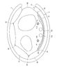
- the sensing cuff 73 directly contacts the area where the artery of the wrist 100 exists, as shown in FIG.
- the sensing cuff 73 is formed in the same shape as the back plate 72 or smaller than the back plate 72 in the longitudinal direction and width direction of the back plate 72.
- the sensing cuff 73 compresses the area where the artery 110 on the flat side of the hand of the wrist 100 is expanded.
- the sensing cuff 73 is pressed toward the living body via the back plate 72 by the expanded pressing cuff 71.
- the sensing cuff 73 includes one air bladder 91, a tube 92 communicating with the air bladder 91, and a connection portion 93 provided at the tip of the tube 92.
- one main surface of the air bladder 91 is fixed to the back plate 72.
- the sensing cuff 73 is attached to the main surface of the back plate 72 on the living body side with a double-sided tape, an adhesive layer, or the like.
- the air bladder 91 is a bag-like structure, and in the present embodiment, the blood pressure measurement device 1 is configured to use air by the pump 14, and thus the air bladder 91 will be described using an air bladder. If a fluid is used, the bag-like structure may be a liquid bag or the like. Such a plurality of air bags 91 are stacked and in fluid communication in the stacking direction.
- the air bag 91 is configured in a rectangular shape that is long in one direction.
- the air bag 91 is configured, for example, by combining two sheet members long in one direction and thermally welding the edges.
- the air bladder 91 includes the fifth sheet member 96a and the sixth sheet member 96b from the living body side.
- a tube 92 fluidly continuous with the internal space of the air bladder 91 is disposed on one side of the fifth sheet member 96a and the sixth sheet member 96b. It is fixed.
- the fifth sheet member 96a and the sixth sheet member 96b form the air bag 91 by welding the peripheral portions of the four sides in a state where the tube 92 is disposed between the fifth sheet member 96a and the sixth sheet member 96b.
- the tubes 92 are welded together.
- the tube 92 is provided at one longitudinal end of the air bladder 91.
- the tube 92 is provided at the end of the air bag 91 near the device body 3.
- the tube 92 has a connecting portion 93 at its tip.
- the tube 92 constitutes a flow path between the device body 3 and the air bladder 91 in the fluid circuit 7.
- the connecting portion 93 is connected to the connected portion 34 a of the flow path cover 34.
- the connection portion 93 is, for example, a nipple.
- the sheet members 86 and 96 that form the pressing cuff 71 and the sensing cuff 73 are made of thermoplastic elastomer.
- thermoplastic elastomers constituting the sheet members 86 and 96 include thermoplastic polyurethane-based resins (Thermoplastic PolyUrethane, hereinafter referred to as TPU), vinyl chloride resin (PolyVinyl Chloride), ethylene vinyl acetate resin (Ethylene-Vinyl Acetate)
- a thermoplastic polystyrene resin (Thermoplastic PolyStyrene), a thermoplastic polyolefin resin (Thermoplastic PolyOlefin), a thermoplastic polyester resin (ThermoPlastic Polyester), and a thermoplastic polyamide resin (Thermoplastic PolyAmide) can be used. It is preferable to use TPU as the thermoplastic elastomer.
- the sheet member may have a single-layer structure, or may have a multi-layer structure.
- the sheet members 86 and 96 are not limited to thermoplastic elastomers, and may be thermosetting elastomers such as silicone, and may be made of thermoplastic elastomer (for example, TPU) and thermosetting elastomer (for example, silicone). It may be a combination.
- thermoplastic elastomer When a thermoplastic elastomer is used for the sheet members 86b, 86c, 86d, and 96 that do not have the guide portion 84, a molding method such as T-die extrusion molding, injection molding, blow molding, or calendar molding is used. In the case of using an elastomeric elastomer, a molding method such as mold casting is used.
- the sheet member 86a having the guide portion 84 uses a molding method such as a modified extrusion molding or an injection molding in which a sheet having irregularities serving as grooves constituting the guide portion 84 is formed in a resin material.
- a forming method such as emboss forming, heat press forming, vacuum forming, pressure forming or the like may be used in which a concavo-convex shape to be a groove constituting the guide portion 84 is formed on a flat sheet.
- the sheet member 86a having the guide portion 84 is a molding method such as mold casting using a mold in which the concave and convex portions to be the groove constituting the guide portion 84 are formed. Is used.
- the sheet members 86 and 96 are formed into a predetermined shape after being formed by each forming method, and the sized pieces are bonded to each other by bonding or welding to form the air bags 81 and 91.
- a bonding method a high frequency welder or laser welding is used when a thermoplastic elastomer is used, and a molecular adhesive is used when a thermosetting elastomer is used.
- the fluid circuit 7 includes a case 11, a pump 14, a flow path 15, an on-off valve 16, a pressure sensor 17, a pressure cuff 71, and a sensing cuff 73.
- the two on-off valves 16 used in the fluid circuit 7 are a first on-off valve 16A and a second on-off valve 16B, and the two pressure sensors 17 are a first pressure sensor 17A and a second pressure sensor 17B. A concrete example will be described.
- the fluid circuit 7 is configured, for example, by branching a first flow path 7 a that continues the pressure cuff 71 from the pump 14 and a middle portion of the first flow path 7 a.
- a second flow path 7b continuous with the sensing cuff 73 and a third flow path 7c connecting the first flow path 7a to the atmosphere are provided.
- the first flow path 7a includes a first pressure sensor 17A.
- a first on-off valve 16A is provided between the first flow passage 7a and the second flow passage 7b.
- the second flow path 7b includes a second pressure sensor 17B.
- a second on-off valve 16B is provided between the first flow path 7a and the third flow path 7c.
- the first flow path 7a and the third flow path 7c are connected, and the pressure cuff 71 and the atmosphere are fluidly connected. Be done.
- the first flow path 7a, the second flow path 7b and the third flow path 7c are connected by opening the first on-off valve 16A and the second on-off valve 16B, and the pressing cuff 71, the sensing cuff 73 and The atmosphere is fluidly connected.
- FIG. 14 is a flowchart showing an example of blood pressure measurement using the blood pressure measurement device 1, and shows both the operation of the user and the operation of the control unit 55.
- 15 to 17 show an example where the user wears the blood pressure measurement device 1 on the wrist 100.
- the user wears the blood pressure measurement device 1 on the wrist 100 (step ST1).
- the user inserts one of the wrists 100 into the curler 5 as shown in FIG.
- the sensing cuff 73 is disposed in the area where the artery 110 on the palm side of the wrist 100 exists.
- the device body 3 is disposed on the back side of the hand of the wrist 100.
- the second belt 62 is passed through the frame 61 d of the tail lock 61 c of the first belt 61 by the hand opposite to the hand where the user placed the blood pressure measurement device 1.
- the first belt 61 and the second belt 62 are connected, and the blood pressure measurement device 1 is attached to the wrist 100.
- the user operates the operation unit 13 to input a command corresponding to the start of measurement of the blood pressure value.
- the operation unit 13 which has performed the input operation of the command outputs an electric signal corresponding to the start of measurement to the control unit 55 (step ST2).
- the control unit 55 receives the electric signal, for example, the control unit 55 opens the first on-off valve 16A and closes the second on-off valve 16B to drive the pump 14 to pass through the first flow path 7a and the second flow path 7b.
- compressed air is supplied to the pressure cuff 71 and the sensing cuff 73 (step ST3).
- the pressure cuff 71 and the sensing cuff 73 start to expand.
- the first pressure sensor 17A and the second pressure sensor 17B respectively detect the pressure of the pressing cuff 71 and the sensing cuff 73, and output an electrical signal corresponding to the pressure to the control unit 55 (step ST4).
- the control unit 55 determines whether the pressure in the internal space of the pressure cuff 71 and the sensing cuff 73 has reached a predetermined pressure for blood pressure measurement, based on the received electrical signal (step ST5). For example, when the internal pressure of the pressure cuff 71 does not reach a predetermined pressure and the internal pressure of the sensing cuff 73 reaches a predetermined pressure, the control unit 55 closes the first on-off valve 16A, and Compressed air is supplied through the flow path 7a.
- the control unit 55 stops the driving of the pump 14 (YES in step ST5).
- the pressing cuff 71 is fully inflated, and the inflated pressing cuff 71 presses the wrist 100 and the back plate 72.
- the pressure cuff 71 has wrinkles along the guide portion 84.
- the sensing cuff 73 is supplied with a predetermined amount of air so that the internal pressure is the pressure required to measure the blood pressure, is inflated, and is attached to the wrist 100 by the back plate 72 pressed by the pressing cuff 71. It is pushed towards. Therefore, the sensing cuff 73 presses the artery 110 in the wrist 100 and occludes the artery 110 as shown in FIG.
- control unit 55 controls the second on-off valve 16B and repeats opening and closing of the second on-off valve 16B or adjusts the degree of opening of the second on-off valve 16B to thereby Pressurize the pressure. Based on the electric signal output from the second pressure sensor 17B in the process of pressurization, the control unit 55 obtains measurement results such as blood pressure values such as systolic and diastolic blood pressure and heart rate.
- the control unit 55 calculates blood pressure in the pressurization process of the pressure cuff 71
- the blood pressure may be calculated in the depressurization process of the pressure cuff 71, or may be calculated in both the pressurization process and the depressurization process of the pressure cuff 71.
- the control unit 55 outputs an image signal corresponding to the obtained measurement result to the display unit 12.
- the display unit 12 When the display unit 12 receives an image signal, the display unit 12 displays the measurement result on the screen. The user visually confirms the display unit 12 to confirm the measurement result. After the measurement is completed, the user removes the rod 61e from the small hole 62a, removes the second belt 62 from the frame 61d, and removes the wrist 100 from the curler 5, whereby the blood pressure measurement device 1 is removed from the wrist 100. Remove.
- the blood pressure measurement device 1 has a guide portion 84 that causes wrinkles on the outer surface of the pressure cuff 71 of the cuff structure 6 on the living body side.
- the pressure cuff 71 is shaped to curve with a predetermined curvature. For this reason, since the curvature radius of the inner peripheral surface side and the outer peripheral surface side is different when the pressure cuff 71 is expanded, the peripheral length of the inner peripheral surface and the peripheral length of the outer peripheral surface are different. Inner / outer circumference difference occurs. Due to the difference between the inner and outer peripheries, a part of the inner peripheral surface of the pressure cuff 71 is bent and wrinkles toward the outer peripheral surface side in the radial direction are generated. The wrinkles generated at this time tend to be deeper at the portion where the radius of curvature is small.
- such a crease may break the inner space of the pressure cuff 71 or may lose the expansion pressure. That is, the wrinkles generated on the inner circumferential surface of the pressing cuff 71 may cause the blood pressure measurement result to be affected, for example, the measurement accuracy of the blood pressure may be lowered and the measurement result may be uneven.
- the blood pressure measurement device 1 of the present embodiment is disposed at a position where the device body 3 and the sensing cuff 73 face each other across the curler 5. For this reason, if a deep crease is generated in the pressure cuff 71 at a midway point from the device body 3 to the sensing cuff 73, there is a risk that the internal space of the pressure cuff 71 may be divided or pressure loss may occur. The pressure in the pressure cuff 71 in the region for pressing the cuff 73 is not increased to a predetermined pressure, and the blood pressure measurement result may not be an accurate value.
- the guide portion 84 serving as a starting point where wrinkles occur when the pressure cuff 71 expands and an inner / outer circumference difference occurs on the inner circumferential surface side and the outer circumferential surface side of the pressure cuff 71
- wrinkles can be generated from the guide portion 84 as a starting point.
- the guide unit 84 can manage the number and depth of wrinkles. . For this reason, when blood pressure is measured, it can prevent that a blood pressure measurement result arises, and it can improve the precision of a blood pressure measurement result.
- the guide portion 84 is provided in a region other than the region where the sensing cuff 73 is disposed, that is, the region avoiding the position facing the artery.
- the occurrence of wrinkles in the area where the sensing cuff 73 is disposed can be suppressed.
- the pressing cuff 71 can press the back plate 72 provided on the sensing cuff 73 with a curved surface, the sensing cuff 73 can be pressed uniformly. For this reason, it can prevent that a wrinkles arise in sensing cuff 73, and sensing cuff 73 can press artery 110 suitably.
- the pressure cuff 71 increases or decreases the thickness of the sheet member 86a.
- the thickness can be made uniform, and wrinkles can be managed with a simple configuration.
- the guide portion 84 can be formed on the first sheet member 86a constituting the pressing cuff 71 when the first sheet member 86a or the pressing cuff 71 is formed, manufacturing of the pressing cuff 71 becomes easy.
- the blood pressure measurement device 1 by providing the guiding portion 84 for generating wrinkles on the main surface of the pressing cuff 71 on the living body side, wrinkles of any position and number can be obtained. Can improve the accuracy of blood pressure measurement results.
- the device body 3 is disposed on the back side of the hand of the wrist 100.
- the device body 3 may be disposed on the palm side of the wrist 100. That is, the device body 3 may be fixed to the outer surface of the area where the sensing cuff 73 of the curler 5 is disposed.
- the blood pressure measurement device 1 having such a configuration is disposed in the area where the artery of the wrist 100 is located by arranging the device body 3 on the palm side, so the distance with the sensing cuff 73 is short, The length of the tube 92 provided in the sensing cuff 73 may be short.
- FIGS. 18 and 19 a second embodiment of the pressure cuff 71 will be described using FIGS. 18 and 19.
- the description of the configuration other than the pressure cuff is omitted.
- the same configurations as those of the blood pressure measurement device 1 according to the first embodiment described above will be described using the same reference numerals, and the detailed description will be omitted.
- FIG. 18 is a plan view schematically showing the configuration of the pressure cuff 71A according to the second embodiment
- FIG. 19 schematically shows the configuration of the blood pressure measurement device 1 using the pressure cuff 71A. It is a side view showing typically the composition at the time of inflation.
- the pressing cuffs 71A are provided with a plurality of guiding portions 84 at equal intervals.
- Such a pressing cuff 71A is provided with a plurality of guiding portions 84 at intervals of 15 mm.
- the pressure cuff 71A can prevent part of the internal space from being divided, and it is possible to press the back plate 72 substantially uniformly without losing expansion pressure, and the pressure cuff 71 described above Similarly, the accuracy of blood pressure measurement results can be improved.
- FIG. 20 and 21 a third embodiment of the pressure cuff 71 will be described using FIGS. 20 and 21.
- FIG. the blood pressure measurement device 1 according to the first embodiment described above and the pressure cuff used for the cuff structure 6 are different from each other. I omit it.
- the same configurations as those of the blood pressure measurement device 1 according to the first embodiment described above will be described using the same reference numerals, and the detailed description will be omitted.
- FIG. 20 is a plan view schematically showing the configuration of a pressure cuff 71B according to the third embodiment
- FIG. 21 schematically shows the configuration of the blood pressure measurement device 1 using the pressure cuff 71B. It is a side view showing typically the composition at the time of inflation.
- the pressing cuffs 71B are provided with a plurality of guiding portions 84 at equal intervals.
- Such a pressure cuff 71A is provided with a plurality of guide portions 84 at intervals of 5 mm.
- the pressure cuff 71B can prevent part of the internal space from being divided, and it is possible to press the back plate 72 substantially uniformly without losing the inflation pressure, and the pressure cuff 71 described above , 71A, the accuracy of blood pressure measurement results can be improved.
- a fourth embodiment of the pressure cuff 71 will be described with reference to FIGS.
- a cuff having a guiding portion 84 in the blood pressure measurement device 1C wound around the upper arm to measure the blood pressure is a structure to be used.
- the same components as those of the blood pressure measurement device 1 according to the first embodiment described above will be described with the same reference numerals, and the description and illustration thereof will be appropriately omitted.
- the blood pressure measurement device 1C in the fourth embodiment includes a device main body 3C and a cuff structure 6C.
- the device body 3C includes, for example, a case 11C, a display unit 12, an operation unit 13, a pump 14, a flow passage unit 15, an open / close valve 16, a pressure sensor 17, a power supply unit 18, and a control board 20. And have.
- the device main body 3 ⁇ / b> C has one pump 14, one on-off valve 16 and one pressure sensor 17.
- the case 11C is configured, for example, in a box shape.
- the case 11C has a mounting portion 11a for fixing the cuff structure 6C.
- the attachment portion 11a is, for example, an opening provided on the back surface of the case 11C.
- the cuff structure 6C is a bag comprising the curler 5, a pressing cuff 71C provided on the living body side of the curler 5, a cloth in which the curler 5 and the pressing cuff 71C are disposed. And a cover body 74.
- the cuff structure 6C is wound around the upper arm.
- the curler 5 has, for example, a protrusion 5a fixed to the mounting portion 11a.
- the pressing cuff 71 ⁇ / b> C includes an air bladder 81 and a guide portion 84 provided on the main surface on one side of the air bladder 81. That is, the pressing cuff 71C is configured to have the guide portion 84 in one air bladder 81.
- the pressing cuff 71 ⁇ / b> C is housed together with the curler 5 in the bag-like cover body 74 and fixed to the inner surface of the curler 5.
- the pressing cuff 71C is attached to the inner surface of the curler 5 with a double-sided tape or an adhesive.
- the air bag 81 is configured in a rectangular shape that is long in one direction.
- the air bag 81 is configured, for example, by combining two sheet members 86 long in one direction and thermally welding the edge.
- the air bladder 81 includes, from the living body side, a first sheet member 86a, and a second sheet member 86b constituting the first sheet member 86a and the air bladder 81.
- the first sheet member 86a has a plurality of guides 84 on the outer surface on the living body side.
- the blood pressure measurement device 1C configured in this way, like the blood pressure measurement device 1 described above, provides the guide portion 84 on the inner surface of the pressing cuff 71C on the living body side, thereby reducing the number and position of wrinkles generated by the inner and outer circumferential difference. It can be managed. As a result, the pressure cuff 71C can prevent part of the internal space from being divided, and it is possible to press the upper arm substantially uniformly without losing the inflation pressure, as in the pressure cuff 71 described above. In addition, the accuracy of the blood pressure measurement results can be improved. As described above, the blood pressure measurement device 1C in which the guide portion 84 is provided on the pressing cuff 71C can improve the accuracy of the blood pressure measurement result even if the cuff structure 6C is wound around the upper arm.
- sheet member 86a first sheet member 86a1: outer surface 86b: second sheet member 86b1: opening 86c: third sheet member 86c1: opening 86d: fourth sheet member 91: bag-like structure 91: air bag 92 ... tube 93 ... connection portion 96 ... sheet member 96a ... fifth sheet member 96b ... sixth sheet member 100 ... wrist 110 ... artery
Landscapes
- Health & Medical Sciences (AREA)
- Life Sciences & Earth Sciences (AREA)
- Cardiology (AREA)
- General Health & Medical Sciences (AREA)
- Biophysics (AREA)
- Physics & Mathematics (AREA)
- Vascular Medicine (AREA)
- Surgery (AREA)
- Molecular Biology (AREA)
- Pathology (AREA)
- Engineering & Computer Science (AREA)
- Biomedical Technology (AREA)
- Heart & Thoracic Surgery (AREA)
- Medical Informatics (AREA)
- Veterinary Medicine (AREA)
- Public Health (AREA)
- Animal Behavior & Ethology (AREA)
- Physiology (AREA)
- Ophthalmology & Optometry (AREA)
- Dentistry (AREA)
- General Physics & Mathematics (AREA)
- Pulmonology (AREA)
- Measuring Pulse, Heart Rate, Blood Pressure Or Blood Flow (AREA)
Priority Applications (3)
| Application Number | Priority Date | Filing Date | Title |
|---|---|---|---|
| DE112018006731.9T DE112018006731T5 (de) | 2017-12-28 | 2018-11-28 | Blutdruckmesseinrichtung |
| CN201880083862.1A CN111526786B (zh) | 2017-12-28 | 2018-11-28 | 血压测量装置 |
| US16/912,771 US12059236B2 (en) | 2017-12-28 | 2020-06-26 | Blood pressure measurement device |
Applications Claiming Priority (2)
| Application Number | Priority Date | Filing Date | Title |
|---|---|---|---|
| JP2017-252899 | 2017-12-28 | ||
| JP2017252899A JP6976841B2 (ja) | 2017-12-28 | 2017-12-28 | 血圧測定装置 |
Related Child Applications (1)
| Application Number | Title | Priority Date | Filing Date |
|---|---|---|---|
| US16/912,771 Continuation US12059236B2 (en) | 2017-12-28 | 2020-06-26 | Blood pressure measurement device |
Publications (1)
| Publication Number | Publication Date |
|---|---|
| WO2019130961A1 true WO2019130961A1 (ja) | 2019-07-04 |
Family
ID=67066980
Family Applications (1)
| Application Number | Title | Priority Date | Filing Date |
|---|---|---|---|
| PCT/JP2018/043759 Ceased WO2019130961A1 (ja) | 2017-12-28 | 2018-11-28 | 血圧測定装置 |
Country Status (5)
| Country | Link |
|---|---|
| US (1) | US12059236B2 (enExample) |
| JP (1) | JP6976841B2 (enExample) |
| CN (1) | CN111526786B (enExample) |
| DE (1) | DE112018006731T5 (enExample) |
| WO (1) | WO2019130961A1 (enExample) |
Families Citing this family (8)
| Publication number | Priority date | Publication date | Assignee | Title |
|---|---|---|---|---|
| US11744476B2 (en) | 2020-08-20 | 2023-09-05 | Apple Inc. | Blood pressure measurement using device with piezoelectric sensor |
| JP7581913B2 (ja) | 2021-01-25 | 2024-11-13 | オムロンヘルスケア株式会社 | カフ及び血圧測定装置 |
| US12251204B2 (en) | 2021-02-03 | 2025-03-18 | Apple Inc. | Blood pressure monitoring system including a liquid filled sensor |
| KR102561633B1 (ko) * | 2021-06-07 | 2023-08-01 | (주)참케어 | 혈압 측정 장치 |
| JP2025516047A (ja) * | 2022-05-19 | 2025-05-26 | コーニンクレッカ フィリップス エヌ ヴェ | 圧力検知アセンブリ、及び圧力検知アセンブリの製造方法 |
| EP4278961A1 (en) * | 2022-05-19 | 2023-11-22 | Koninklijke Philips N.V. | Pressure sensing assemblies and methods of making the same |
| JP2024090018A (ja) * | 2022-12-22 | 2024-07-04 | オムロンヘルスケア株式会社 | カフ構造体及び血圧測定装置 |
| EP4663109A1 (en) * | 2024-06-12 | 2025-12-17 | Koninklijke Philips N.V. | Pressure measuring device to be used for determining a physiological parameter of a subject |
Citations (5)
| Publication number | Priority date | Publication date | Assignee | Title |
|---|---|---|---|---|
| JP2000051165A (ja) * | 1998-08-05 | 2000-02-22 | Sekisui Chem Co Ltd | 脈波検出用カフ |
| JP2005329162A (ja) * | 2004-05-21 | 2005-12-02 | Fukuda Denshi Co Ltd | 指用カフ |
| JP2007175185A (ja) * | 2005-12-27 | 2007-07-12 | Omron Healthcare Co Ltd | 血圧計用カフおよびこれを備えた血圧計 |
| JP2011200607A (ja) * | 2010-03-26 | 2011-10-13 | Terumo Corp | 電子血圧計 |
| WO2014102870A1 (ja) * | 2012-12-27 | 2014-07-03 | テルモ株式会社 | 血圧計 |
Family Cites Families (22)
| Publication number | Priority date | Publication date | Assignee | Title |
|---|---|---|---|---|
| US4860761A (en) * | 1985-04-12 | 1989-08-29 | Omron Tateisi Electronics Co. | Pulse wave detecting apparatus for blood pressure measurement |
| JPS6272315A (ja) * | 1985-09-25 | 1987-04-02 | 松下電工株式会社 | 血圧計のカフ帯 |
| US6336901B1 (en) * | 1998-04-27 | 2002-01-08 | Omron Corporation | Sphygmomanometer cuff achieving precise measurement of blood pressure |
| JP4742576B2 (ja) * | 2004-12-10 | 2011-08-10 | オムロンヘルスケア株式会社 | 血圧計用カフおよびこれを備えた血圧計 |
| JP4595573B2 (ja) * | 2005-02-04 | 2010-12-08 | オムロンヘルスケア株式会社 | 血圧計用カフおよびその製造方法ならびに血圧計 |
| JP2006218178A (ja) * | 2005-02-14 | 2006-08-24 | Omron Healthcare Co Ltd | 血圧計用カフおよび血圧計 |
| JP4470868B2 (ja) * | 2005-11-22 | 2010-06-02 | パナソニック電工株式会社 | 生体情報計測装置 |
| JP4325639B2 (ja) * | 2005-12-05 | 2009-09-02 | オムロンヘルスケア株式会社 | 血圧測定装置 |
| JP2007275484A (ja) * | 2006-04-12 | 2007-10-25 | Omron Healthcare Co Ltd | 血圧計用カフ |
| JP4552919B2 (ja) * | 2006-10-05 | 2010-09-29 | オムロンヘルスケア株式会社 | 血圧計用カフおよび血圧計 |
| JP5060351B2 (ja) * | 2008-03-12 | 2012-10-31 | トヨタ自動車株式会社 | コラム付けニーエアバッグ装置 |
| JP5076996B2 (ja) * | 2008-03-19 | 2012-11-21 | オムロンヘルスケア株式会社 | 血圧情報測定装置 |
| JP5169552B2 (ja) * | 2008-07-07 | 2013-03-27 | オムロンヘルスケア株式会社 | 血圧情報測定装置用カフおよびこれを備えた血圧情報測定装置 |
| US20110040313A1 (en) * | 2009-08-14 | 2011-02-17 | Dlugos Jr Daniel F | Implantable restriction device with protective member |
| JP5536586B2 (ja) * | 2010-08-17 | 2014-07-02 | 日本光電工業株式会社 | 血圧測定装置 |
| US20120150051A1 (en) * | 2010-12-09 | 2012-06-14 | Welch Allyn, Inc. | Blood pressure cuff |
| JP2012210374A (ja) * | 2011-03-31 | 2012-11-01 | Omron Healthcare Co Ltd | 血圧情報測定装置用カフおよびこれを備えた血圧情報測定装置 |
| JP2013146539A (ja) * | 2011-12-21 | 2013-08-01 | Nippon Koden Corp | カフ及びそれを用いた加圧下における組織観察方法 |
| JP2013192878A (ja) * | 2012-03-22 | 2013-09-30 | Terumo Corp | 血圧計 |
| JP6051732B2 (ja) * | 2012-09-25 | 2016-12-27 | オムロンヘルスケア株式会社 | 血圧情報測定装置用カフ及び血圧情報測定装置 |
| WO2014102871A1 (ja) | 2012-12-27 | 2014-07-03 | テルモ株式会社 | 血圧計 |
| US11026592B2 (en) * | 2017-09-29 | 2021-06-08 | Fitbit, Inc. | Finger blood pressure cuff |
-
2017
- 2017-12-28 JP JP2017252899A patent/JP6976841B2/ja active Active
-
2018
- 2018-11-28 CN CN201880083862.1A patent/CN111526786B/zh active Active
- 2018-11-28 WO PCT/JP2018/043759 patent/WO2019130961A1/ja not_active Ceased
- 2018-11-28 DE DE112018006731.9T patent/DE112018006731T5/de active Pending
-
2020
- 2020-06-26 US US16/912,771 patent/US12059236B2/en active Active
Patent Citations (5)
| Publication number | Priority date | Publication date | Assignee | Title |
|---|---|---|---|---|
| JP2000051165A (ja) * | 1998-08-05 | 2000-02-22 | Sekisui Chem Co Ltd | 脈波検出用カフ |
| JP2005329162A (ja) * | 2004-05-21 | 2005-12-02 | Fukuda Denshi Co Ltd | 指用カフ |
| JP2007175185A (ja) * | 2005-12-27 | 2007-07-12 | Omron Healthcare Co Ltd | 血圧計用カフおよびこれを備えた血圧計 |
| JP2011200607A (ja) * | 2010-03-26 | 2011-10-13 | Terumo Corp | 電子血圧計 |
| WO2014102870A1 (ja) * | 2012-12-27 | 2014-07-03 | テルモ株式会社 | 血圧計 |
Also Published As
| Publication number | Publication date |
|---|---|
| US20200323446A1 (en) | 2020-10-15 |
| CN111526786A (zh) | 2020-08-11 |
| JP6976841B2 (ja) | 2021-12-08 |
| DE112018006731T5 (de) | 2020-09-10 |
| CN111526786B (zh) | 2024-07-26 |
| JP2019118407A (ja) | 2019-07-22 |
| US12059236B2 (en) | 2024-08-13 |
Similar Documents
| Publication | Publication Date | Title |
|---|---|---|
| WO2019130961A1 (ja) | 血圧測定装置 | |
| JP7019415B2 (ja) | 血圧測定装置 | |
| JP6896610B2 (ja) | 血圧測定装置 | |
| CN111526783B (zh) | 血压测量装置 | |
| WO2019130962A1 (ja) | 血圧測定装置 | |
| JP7027174B2 (ja) | 血圧測定装置 | |
| JP7019416B2 (ja) | 血圧測定装置 | |
| WO2019135370A1 (ja) | カフ構造体、血圧測定装置、カフ構造体の製造方法、及び血圧測定装置の製造方法 | |
| JP7175739B2 (ja) | 血圧測定装置 | |
| JP6896611B2 (ja) | 血圧測定装置 | |
| US20230355115A1 (en) | Cuff and blood pressure measurement device | |
| WO2019139037A1 (ja) | 血圧測定装置 | |
| WO2019139038A1 (ja) | ベルト、血圧測定装置、及びベルトの製造方法 |
Legal Events
| Date | Code | Title | Description |
|---|---|---|---|
| 121 | Ep: the epo has been informed by wipo that ep was designated in this application |
Ref document number: 18896943 Country of ref document: EP Kind code of ref document: A1 |
|
| 122 | Ep: pct application non-entry in european phase |
Ref document number: 18896943 Country of ref document: EP Kind code of ref document: A1 |