WO2019130875A1 - トルクセンサにおける零点誤差の補正方法 - Google Patents
トルクセンサにおける零点誤差の補正方法 Download PDFInfo
- Publication number
- WO2019130875A1 WO2019130875A1 PCT/JP2018/042150 JP2018042150W WO2019130875A1 WO 2019130875 A1 WO2019130875 A1 WO 2019130875A1 JP 2018042150 W JP2018042150 W JP 2018042150W WO 2019130875 A1 WO2019130875 A1 WO 2019130875A1
- Authority
- WO
- WIPO (PCT)
- Prior art keywords
- torque
- rated
- zero point
- sensor
- loop
- Prior art date
- Legal status (The legal status is an assumption and is not a legal conclusion. Google has not performed a legal analysis and makes no representation as to the accuracy of the status listed.)
- Ceased
Links
Images


Classifications
-
- G—PHYSICS
- G01—MEASURING; TESTING
- G01L—MEASURING FORCE, STRESS, TORQUE, WORK, MECHANICAL POWER, MECHANICAL EFFICIENCY, OR FLUID PRESSURE
- G01L25/00—Testing or calibrating of apparatus for measuring force, torque, work, mechanical power, or mechanical efficiency
- G01L25/003—Testing or calibrating of apparatus for measuring force, torque, work, mechanical power, or mechanical efficiency for measuring torque
-
- G—PHYSICS
- G01—MEASURING; TESTING
- G01L—MEASURING FORCE, STRESS, TORQUE, WORK, MECHANICAL POWER, MECHANICAL EFFICIENCY, OR FLUID PRESSURE
- G01L25/00—Testing or calibrating of apparatus for measuring force, torque, work, mechanical power, or mechanical efficiency
-
- G—PHYSICS
- G01—MEASURING; TESTING
- G01L—MEASURING FORCE, STRESS, TORQUE, WORK, MECHANICAL POWER, MECHANICAL EFFICIENCY, OR FLUID PRESSURE
- G01L3/00—Measuring torque, work, mechanical power, or mechanical efficiency, in general
- G01L3/02—Rotary-transmission dynamometers
- G01L3/04—Rotary-transmission dynamometers wherein the torque-transmitting element comprises a torsionally-flexible shaft
- G01L3/10—Rotary-transmission dynamometers wherein the torque-transmitting element comprises a torsionally-flexible shaft involving electric or magnetic means for indicating
Definitions
- the present invention relates to a method of correcting a zero point error in a torque sensor.
- the sensor output value when no torque is applied may fluctuate due to ambient temperature change, aging, and the like.
- Such a zero point error in which an output error occurs when the torque is zero may reduce the detection accuracy of the torque sensor.
- the present invention is intended to solve the above-mentioned problems, and it is an object of the present invention to provide a method of correcting a zero point error in a torque sensor for efficiently correcting an output error at a torque zero point even if hysteresis is present. .
- a method of correcting a zero point error in a torque sensor is a method of correcting a zero point error in a torque sensor that corrects an output error when the torque is zero in a torque sensor that detects a torque of a rotational drive shaft.
- the hysteresis loop obtained by applying the positive rotation torque and the desired negative rotation torque is defined in advance, and two new output values at the torque zero point in the hysteresis loop are used to set a new zero point.
- the output error at the torque zero point can be efficiently corrected even if the hysteresis is present.
- FIG. 1A is a side view of the torque sensor
- FIG. 1B is a top view of the torque sensor. It is the figure which exaggerated and showed the hysteresis loop used in the correction method of the zero point error in the torque sensor which concerns on Embodiment 1 of this invention. It is the figure which exaggerated and showed the hysteresis loop used in the correction method of the zero point error in the torque sensor which concerns on Embodiment 2 of this invention.
- Embodiment 1 A method of correcting the zero error in the torque sensor according to the first embodiment of the present invention will be described with reference to FIG. 1 and FIG.
- FIGS. 1A and 1B are diagrams showing an example of a mounting structure of a torque sensor to which a method of correcting a zero error according to a first embodiment of the present invention is applied.
- the torque detector 10 detects the magnitude of the torque applied to the rotational load system from the rotational drive system, and includes a torque sensor 11, a fixing plate 12, and a sensor shaft 13. , And flanges 14 and 15 are provided.
- the sensor shaft 13 and the flanges 14 and 15 are coaxially arranged.
- the shaft diameter of the sensor shaft 13 is smaller than the shaft diameter of the flanges 14 and 15, and the shaft diameters of the flanges 14 and 15 are the same.
- the flange portion 14 is provided coaxially with the rotary drive shaft 21 on the end face of the rotary drive shaft 21 of the motor serving as the rotary drive system.
- the flange portion 15 is provided coaxially with the torque transmission shaft 22 on the end face of the torque transmission shaft 22 which is a rotational load system.
- the sensor shaft 13 is disposed between the flanges 14 and 15.
- the torque sensor 11 is a strain gauge type sensor, and is fixed to the flanges 14 and 15 via the fixing plate 12.
- the fixing plate 12 is fixed across the outer peripheral surfaces of the flanges 14 and 15. That is, the torque sensor 11 fixed to the fixed plate 12 is disposed radially outside the sensor shaft 13 and is opposed to the sensor shaft 13 in the radial direction.
- the torque sensor 11 rotates with the rotary drive shaft 21 and the torque transmission shaft 22, and the torque generated by the rotation of the rotary drive shaft 21 is distorted when it is transmitted from the rotary drive shaft 21 to the torque transmission shaft 22. And convert the amount of distortion into the size of torque and output it.
- the torque sensor 11 is provided across the outer peripheral surfaces of the flanges 14 and 15, the torque sensor 11 is easily distorted in the rotational direction, and the detection sensitivity to the applied torque is improved.
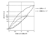
- FIG. 2 is an exaggerated view of a hysteresis loop used in the method of correcting the zero point error in the torque sensor according to the first embodiment.
- the hysteresis loop shown in FIG. 2 is a closed curve showing the relationship between the torque applied to the torque sensor 11 and the sensor output value of the torque sensor 11.
- the hysteresis present in the torque sensor 11 generates an output error at a torque zero point (hereinafter referred to as a zero point error), and is not only due to the mechanical characteristics of the constituent material in the torque sensor 11 It also originates in the mounting state of the torque sensor 11.
- a zero point error a torque zero point
- the hysteresis loop it is known that when the history is the same, loop shape reproducibility (repeatability) is obtained, and when the history is different, different loop shapes are drawn.
- the method of correcting the zero error in the torque sensor 11 according to the first embodiment is based on the torque applied to the torque sensor 11 and the sensor output value of the torque sensor 11, the hysteresis loop existing in the torque sensor 11.
- the zero point error is corrected according to the size and loop shape of the hysteresis loop.
- the correction method of the zero point error in the torque sensor 11 according to the first embodiment can remove the hysteresis component causing the output error from the sensor output value at the torque zero point.
- P1 is a sensor output value at the time of applying the rated torque of positive rotation, when demonstrating the rated loop shown by the continuous line of FIG.
- P2 is a sensor output value when a rated torque for negative rotation is applied.
- two sensor output values P3 and P4 exist at the torque zero point.
- the sensor output value P3 is generated when the rotational drive shaft 21 is rotated forward to apply a rated torque for positive rotation to the torque sensor 11, and then the rotational angle position of the rotational drive shaft 21 is returned to zero.
- Zero output ie, zero error.
- the sensor output value P4 is generated when the rotational drive shaft 21 is negatively rotated to apply a rated torque of negative rotation to the torque sensor 11, and then the rotational angle position of the rotational drive shaft 21 is returned to zero.
- Zero output, ie, zero error is generated when the rotational drive shaft 21 is negatively rotated to apply a rated torque of negative rotation to the torque sensor 11, and then the rotational angle position of the rotational drive shaft 21 is returned to zero.
- the central value Po of the sensor output values P3 and P4 is set as a new zero at the torque zero.
- the newly set zero point becomes the reference point of the sensor output value when the motor rated control is performed next.
- the torque sensor 11 sets the central value Po of the sensor output values P3 and P4 obtained from the rated loop as a new zero point at the torque zero point, thereby covering the entire rotation angle range of the rotary drive shaft 21. , Output error can be suppressed.
- the zero point error may be corrected according to the size and loop shape of the hysteresis loop corresponding to the drive control of the motor.
- the positive rotation torque is a torque equal to or less than the rated torque.
- the positive rotation torque is a torque that is 0.5 times the rated torque, while the negative rotation torque is a rated torque.
- the above-described hysteresis loop is hereinafter referred to as a rated 0.5 loop.
- P1 ' is a sensor output value when a rated positive 0.5 torque (a torque which is 0.5 times the rated torque) is applied. It is.
- P2 is a sensor output value when a negative torque rated torque is applied, and is common to the rated loop. Further, two sensor output values P3 'and P4 are present at the torque zero point.
- the sensor output value P3 causes the rotational drive shaft 21 to rotate positively, and after applying a rated torque of positive rotation 0.5 torque to the torque sensor 11, returns the rotational angle position of the rotational drive shaft 21 to zero degrees.
- Zero output that is, the zero error.
- the sensor output value P4 is generated when the rotational drive shaft 21 is negatively rotated to apply a rated torque of negative rotation to the torque sensor 11, and then the rotational angle position of the rotational drive shaft 21 is returned to zero.
- Zero output, ie, zero error which is common to the rated loop.
- the center value Po 'of the sensor output values P3' and P4 is set as a new zero point at the torque zero point.
- the newly set zero point becomes the reference point of the sensor output value when the motor rated 0.5 control is subsequently performed.
- the torque sensor 11 sets the central value Po 'of the sensor output values P3' and P4 obtained from the rated 0.5 loop as a new zero point at the torque zero point, whereby the rotation angle of the rotary drive shaft 21 is obtained.
- the output error can be suppressed over the entire range.
- the central value of the two sensor output values at the torque zero is set as a new zero.
- Second Embodiment A method of correcting the zero error in the torque sensor according to the second embodiment of the present invention will be described with reference to FIG.
- the correction method of the zero error in the torque sensor 11 according to the second embodiment is applied only to the rated loop, and the correction has a loop area smaller than the loop area of the rated loop apart from the rated loop.
- the hysteresis loop is defined in advance.
- the above-mentioned correction hysteresis loop is hereinafter referred to as a correction loop.
- correction loop indicated by the two-dot chain line in FIG. 3 is used to set the central value Po of the sensor output values P3 and P4 in the rating loop indicated by the solid line in FIG.
- the negative rotational torque in the correction loop is the rated torque.
- the positive rotation torque in the correction loop is smaller than the rated torque, and the hysteresis loop passes through the center value Po of the sensor output values P3 and P4 in the rated loop when the rotational angle position of the rotary drive shaft 21 is zero degree. It has become a torque that can draw.
- the correction loop shown by the two-dot chain line in FIG. 3 is an example of a correction loop, and the positive rotation torque is a torque that is 0.625 times the rated torque, while the negative rotation torque is rated Rated torque is 0.625 loop.
- the rated loop is defined in advance as described above, before performing the rated control of the motor.
- a rated torque for negative rotation is applied, and then a rated torque of 0.625 for positive rotation (a torque that is 0.625 times the rated torque) is applied, and then the rotational angle position of the rotary drive shaft 21 is returned to zero.
- a rated torque for negative rotation is applied, and then a rated torque of 0.625 for positive rotation (a torque that is 0.625 times the rated torque) is applied, and then the rotational angle position of the rotary drive shaft 21 is returned to zero.
- the sensor output values at the torque zero point in the rated 0.625 loop are H3 and H4, and among these, the positive sensor output value H3 is the central value Po of the sensor output values P3 and P4 in the rated loop.
- the central value Po of the sensor output values P3 and P4 is set as a new zero at the torque zero.
- the newly set zero point becomes the reference point of the sensor output value when the motor rated control is performed next.
- the torque sensor 11 sets the central value Po of the sensor output values P3 and P4 obtained from the rating loop and the correction loop as a new zero point at the torque zero point, whereby the rotation angle range of the rotary drive shaft 21 is obtained.
- the output error can be suppressed over the entire area.
- the hysteresis for correction that passes through the central value of the two sensor output values at the torque zero with respect to the rated hysteresis loop of the torque sensor 11 By drawing a loop and setting the center value as a new zero point, even if the torque sensor 11 has hysteresis, it is possible to efficiently correct the output error at the torque zero point.
- the correction method of the zero point error in the torque sensor according to the present invention can efficiently correct the output error at the torque zero point even if hysteresis exists, and is suitable for use in the correction method of the zero point error in the torque sensor There is.
Landscapes
- Physics & Mathematics (AREA)
- General Physics & Mathematics (AREA)
- Force Measurement Appropriate To Specific Purposes (AREA)
- Control Of Electric Motors In General (AREA)
Abstract
回転駆動軸(21)のトルクを検出するトルクセンサ(11)において、トルクが零のときの出力誤差を補正するトルクセンサにおける零点誤差の補正方法であって、所望の正回転トルク及び所望の負回転トルクを印加することによって得られるヒステリシスループを、予め規定し、そのヒステリシスループにおけるトルク零点での2つの出力値(P3,P4)を用いて、新たな零点を設定する。
Description
この発明は、トルクセンサにおける零点誤差の補正方法に関する。
従来、モータ及びエンジン等の回転駆動系におけるトルクを検出する手段として、種々のトルクセンサが提供されている。このような、従来のトルクセンサとしては、例えば、特許文献1に開示されている。
トルクセンサにおいては、周囲の温度変化及び経年変化等に起因して、トルクが印加されていないときのセンサ出力値、即ち、零点出力が変動する場合がある。このような、トルク零のときに出力誤差が生じる零点誤差は、トルクセンサの検出精度を低下させるおそれがある。
そこで、従来、トルクセンサにおける零点誤差の補正方法については、様々ものが提供されている。しかしながら、トルクセンサの中には、ヒステリシスを含むものもあり、このような、ヒステリシスが存在するトルクセンサにおいても、零点誤差を効率的に補正する必要がある。
この発明は、上記課題を解決するものであって、ヒステリシスが存在しても、トルク零点における出力誤差を効率的に補正するためのトルクセンサにおける零点誤差の補正方法を提供することを目的とする。
この発明に係るトルクセンサにおける零点誤差の補正方法は、回転駆動軸のトルクを検出するトルクセンサにおいて、トルクが零のときの出力誤差を補正するトルクセンサにおける零点誤差の補正方法であって、所望の正回転トルク及び所望の負回転トルクを印加することによって得られるヒステリシスループを、予め規定し、ヒステリシスループにおけるトルク零点での2つの出力値を用いて、新たな零点を設定するものである。
この発明によれば、ヒステリシスが存在しても、トルク零点における出力誤差を効率的に補正することができる。
以下、この発明の実施の形態について図面を参照しながら詳細に説明する。
実施の形態1.
この発明の実施の形態1に係るトルクセンサにおける零点誤差の補正方法について、図1及び図2を用いて説明する。
この発明の実施の形態1に係るトルクセンサにおける零点誤差の補正方法について、図1及び図2を用いて説明する。
図1A及び図1Bは、この発明の実施の形態1に係る零点誤差の補正方法が適用されるトルクセンサの取付構造の一例を示した図である。図1A及び図1Bに示すように、トルク検出器10は、回転駆動系から回転負荷系に負荷されるトルクの大きさを検出するものであって、トルクセンサ11、固定板12、センサ軸13、及び、フランジ部14,15を備えている。
センサ軸13とフランジ部14,15とは、同軸状に配置されている。センサ軸13の軸径は、フランジ部14,15の軸径よりも小径となっており、フランジ部14,15の軸径は、同じ軸径となっている。
フランジ部14は、回転駆動系となるモータの回転駆動軸21の端面に、当該回転駆動軸21と同軸状に設けられている。一方、フランジ部15は、回転負荷系となるトルク伝達軸22の端面に、当該トルク伝達軸22と同軸状に設けられている。そして、センサ軸13は、フランジ部14,15間に配置されている。
トルクセンサ11は、歪みゲージ式のセンサであって、固定板12を介してフランジ部14,15に固定されている。固定板12は、フランジ部14,15の外周面に跨って固定されている。つまり、固定板12に固定されたトルクセンサ11は、センサ軸13の径方向外側に配置されており、当該センサ軸13と径方向において対向している。
従って、トルクセンサ11は、回転駆動軸21及びトルク伝達軸22と共に回転し、回転駆動軸21の回転によって発生したトルクが、当該回転駆動軸21からトルク伝達軸22に伝達される際に、歪を生じて、その歪量をトルクの大きさに換算して出力する。このとき、トルクセンサ11は、フランジ部14,15の外周面に跨って設けられているため、回転方向に向けて歪み易くなっており、印加されるトルクに対する検出感度を向上させている。
次に、実施の形態1に係るトルクセンサ11における零点誤差の補正方法について、図2を用いて説明する。図2は、実施の形態1に係るトルクセンサにおける零点誤差の補正方法において使用されるヒステリシスループを誇張して示した図である。そして、図2に示したヒステリシスループは、トルクセンサ11に印加されるトルクと、トルクセンサ11のセンサ出力値との関係を示した閉曲線となっている。
ここで、トルクセンサ11に存在するヒステリシスは、トルク零点における出力誤差(以下、零点誤差と称す)を発生させるものであって、トルクセンサ11における構成材料の機械的特性に起因するだけでなく、トルクセンサ11の取付状態にも起因する。また、ヒステリシスループについては、履歴が同じであると、ループ形状の再現性(繰り返し性)を有し、履歴が異なると、異なるループ形状を描くことが、知られている。
そこで、実施の形態1に係るトルクセンサ11における零点誤差の補正方法は、トルクセンサ11に印加されるトルクと、トルクセンサ11のセンサ出力値とに基づいて、当該トルクセンサ11に存在するヒステリシスループを予め規定し、所望のモータ駆動制御を行うのに先立って、そのヒステリシスループの大きさ及びループ形状に応じて、零点誤差を補正する。これにより、実施の形態1に係るトルクセンサ11における零点誤差の補正方法は、トルク零点におけるセンサ出力値から、その出力誤差の発生原因となるヒステリシス成分を除去することができる。
具体的に、先ず、モータの定格制御を行う場合には、当該モータの定格制御を行うのに先立って、トルクセンサ11に対して、所望の正回転の定格トルク及び所望の負回転の定格トルクを順に印加して、それらを除去した後、印加した定格トルクと、これに対応するセンサ出力値との関係を求める。このとき、トルクセンサ11にヒステリシスが存在する場合には、上述した関係は、図2の実線で示すような、定格ヒステリシスループを形成する。なお、上述した定格ヒステリシスループについては、以下、定格ループと称す。
図2の実線で示した定格ループについて説明すると、P1は、正回転の定格トルクを印加したときのセンサ出力値である。P2は、負回転の定格トルクを印加したときのセンサ出力値である。また、トルク零点には、2つのセンサ出力値P3,P4が存在している。
つまり、センサ出力値P3は、回転駆動軸21を正回転させて、トルクセンサ11に正回転の定格トルクを印加させた後、その回転駆動軸21の回転角度位置を零度に戻したときに発生する零点出力、即ち、零点誤差である。一方、センサ出力値P4は、回転駆動軸21を負回転させて、トルクセンサ11に負回転の定格トルクを印加させた後、その回転駆動軸21の回転角度位置を零度に戻したときに発生する零点出力、即ち、零点誤差である。
そして、センサ出力値P3,P4の中心値Poは、トルク零点における新たな零点として設定される。この新たに設定された零点は、次にモータの定格制御を行う際に、センサ出力値の基準点となる。このように、トルクセンサ11は、定格ループから求めたセンサ出力値P3,P4の中心値Poを、トルク零点における新たな零点と設定することにより、回転駆動軸21の回転角度範囲全域に亘って、出力誤差を抑制することができる。
また、モータの駆動制御を定格制御としない場合には、そのモータの駆動制御に対応したヒステリシスループの大きさ及びループ形状に応じて、零点誤差を補正すれば良い。
例えば、図2の2点鎖線で示したヒステリシスループは、正回転トルクを、定格トルク以下のトルクとしている。具体的に、図2の2点鎖線で示したヒステリシスループは、正回転トルクを、定格トルクの0.5倍となるトルクとする一方、負回転トルクを、定格トルクとしている。なお、上述したヒステリシスループについては、以下、定格0.5ループと称す。
図2の2点鎖線で示した定格0.5ループについて説明すると、P1´は、正回転の定格0.5トルク(定格トルクの0.5倍となるトルク)を印加したときのセンサ出力値である。P2は、負回転の定格トルクを印加したときのセンサ出力値であって、定格ループと共通している。また、トルク零点には、2つのセンサ出力値P3´,P4が存在している。
つまり、センサ出力値P3´は、回転駆動軸21を正回転させて、トルクセンサ11に正回転の定格0.5トルクを印加させた後、その回転駆動軸21の回転角度位置を零度に戻したときに発生する零点出力、即ち、零点誤差である。一方、センサ出力値P4は、回転駆動軸21を負回転させて、トルクセンサ11に負回転の定格トルクを印加させた後、その回転駆動軸21の回転角度位置を零度に戻したときに発生する零点出力、即ち、零点誤差であって、定格ループと共通している。
そして、センサ出力値P3´,P4の中心値Po´は、トルク零点における新たな零点として設定される。この新たに設定された零点は、次にモータの定格0.5制御を行う際に、センサ出力値の基準点となる。このように、トルクセンサ11は、定格0.5ループから求めたセンサ出力値P3´,P4の中心値Po´を、トルク零点における新たな零点と設定することにより、回転駆動軸21の回転角度範囲全域に亘って、出力誤差を抑制することができる。
更に、トルク零点における中心値Po,Po´を高精度に算出したい場合には、定格ループ及び定格0.5ループを予め規定する際に、正回転トルク及び負回転トルクを、それぞれ複数回印加すれば良い。この結果、高い再現性を有する定格ループ及び定格0.5ループを得ることができるので、中心値Po,Po´を高精度に算出することができる。
以上より、実施の形態1に係るトルクセンサ11における零点誤差の補正方法によれば、トルクセンサ11のヒステリシスループにおいて、トルク零点における2つのセンサ出力値の中心値を、新たな零点として設定することにより、トルクセンサ11にヒステリシスが存在しても、トルク零点における出力誤差を効率的に補正することができる。
実施の形態2.
この発明の実施の形態2に係るトルクセンサにおける零点誤差の補正方法について、図3を用いて説明する。
この発明の実施の形態2に係るトルクセンサにおける零点誤差の補正方法について、図3を用いて説明する。
実施の形態2に係るトルクセンサ11における零点誤差の補正方法は、定格ループのみに適用されるものであって、その定格ループとは別に、当該定格ループのループ領域よりも小さいループ領域を有する補正用ヒステリシスループを予め規定する。なお、上述した補正用ヒステリシスループについては、以下、補正用ループと称す。
具体的に、図3の2点鎖線で示した補正用ループは、図3の実線で示した定格ループにおけるセンサ出力値P3,P4の中心値Poを設定するために用いられる。
ここで、補正用ループにおける負回転トルクは、定格トルクとなっている。一方、補正用ループにおける正回転トルクは、定格トルクよりも小さく、且つ、定格ループにおけるセンサ出力値P3,P4の中心値Poを、回転駆動軸21の回転角度位置が零度のときに通り抜けるヒステリシスループを描くことができるトルクとなっている。
なお、図3の2点鎖線で示した補正用ループは、補正用ループの一例であって、正回転トルクを、定格トルクの0.625倍となるトルクとする一方、負回転トルクを、定格トルクとした、定格0.625ループとなっている。
従って、定格トルクが印加されるトルクセンサ11における零点誤差を補正する場合には、先ず、モータの定格制御を行うのに先立って、上述したように、定格ループを予め規定する。
次いで、負回転の定格トルクを印加し、引き続き、正回転の定格0.625トルク(定格トルクの0.625倍となるトルク)を印加した後、回転駆動軸21の回転角度位置を零度に戻すことにより、図3の2点鎖線で示した補正用ループとなる定格0.625ループを得ることができる。
このとき、定格0.625ループにおけるトルク零点でのセンサ出力値は、H3,H4となっており、このうち、正のセンサ出力値H3は、定格ループにおけるセンサ出力値P3,P4の中心値Poと一致する。
そして、センサ出力値P3,P4の中心値Poは、トルク零点における新たな零点として設定される。この新たに設定された零点は、次にモータの定格制御を行う際に、センサ出力値の基準点となる。このように、トルクセンサ11は、定格ループ及び補正用ループから求めたセンサ出力値P3,P4の中心値Poを、トルク零点における新たな零点と設定することにより、回転駆動軸21の回転角度範囲全域に亘って、出力誤差を抑制することができる。
但し、上述したように、補正用ループを規定する際に、他方の負回転トルクを、定格トルクとし、一方の正回転トルクを、定格トルクよりも小さいトルクとした場合には、トルク零点における正のセンサ出力値が新たな零点となる。これに対して、補正用ループを規定する際に、一方の正回転トルクを、定格トルクとし、他方の負回転トルクを、定格トルクよりも小さいトルクとした場合には、トルク零点における負のセンサ出力値が新たな零点となる。
以上より、実施の形態2に係るトルクセンサ11における零点誤差の補正方法によれば、トルクセンサ11の定格ヒステリシスループに対して、そのトルク零点における2つのセンサ出力値の中心値を通り抜ける補正用ヒステリシスループを描いて、その中心値を新たな零点として設定することにより、トルクセンサ11にヒステリシスが存在しても、トルク零点における出力誤差を効率的に補正することができる。
なお、本願発明は、その発明の範囲内において、各実施の形態の自由な組み合わせ、あるいは、各実施の形態における任意の構成要素の変形、もしくは、各実施の形態における任意の構成要素の省略が可能である。例えば、上述した実施の形態1,2におけるトルクセンサ11は、一例を示したものであって、ヒステリシスが存在するトルクセンサであれば、どのような構成のトルクセンサであっても構わない。
この発明に係るトルクセンサにおける零点誤差の補正方法は、ヒステリシスが存在しても、トルク零点における出力誤差を効率的に補正することができ、トルクセンサにおける零点誤差の補正方法に用いるのに適している。
10 トルク検出器
11 トルクセンサ
12 固定板
13 センサ軸
14,15 フランジ部
21 回転駆動軸
22 トルク伝達軸
P1~P4,P1´,P3´,H3,H4 センサ出力値
Po,Po´ 中心値
11 トルクセンサ
12 固定板
13 センサ軸
14,15 フランジ部
21 回転駆動軸
22 トルク伝達軸
P1~P4,P1´,P3´,H3,H4 センサ出力値
Po,Po´ 中心値
Claims (4)
- 回転駆動軸のトルクを検出するトルクセンサにおいて、トルクが零のときの出力誤差を補正するトルクセンサにおける零点誤差の補正方法であって、
所望の正回転トルク及び所望の負回転トルクを印加することによって得られるヒステリシスループを、予め規定し、
前記ヒステリシスループにおけるトルク零点での2つの出力値を用いて、新たな零点を設定する
ことを特徴とするトルクセンサにおける零点誤差の補正方法。 - 前記2つの出力値の中心値を、新たな零点として設定する
ことを特徴とする請求項1記載のトルクセンサにおける零点誤差の補正方法。 - 前記ヒステリシスループは、印加される正回転トルク及び負回転トルクが定格トルクとなる定格ヒステリシスループであって、
前記定格ヒステリシスループのループ領域よりも小さいループ領域を有する補正用ヒステリシスループを、更に規定し、
前記補正用ヒステリシスループは、
印加される正回転トルク及び負回転トルクのいずれか一方のトルクを、定格トルクとする一方、
印加される正回転トルク及び負回転トルクのいずれか他方のトルクを、定格トルクよりも小さく、且つ、前記定格ヒステリシスループにおける前記2つの出力値の中心値を、前記回転駆動軸の回転角度位置が零度のときに通り抜けるヒステリシスループを描くことができるトルクとし、
前記補正用ヒステリシスループが通り抜けた前記中心値を、新たな零点として設定する
ことを特徴とする請求項1記載のトルクセンサにおける零点誤差の補正方法。 - 前記ヒステリシスループは、正回転トルク及び負回転トルクを複数回印加することによって得られる
ことを特徴とする請求項1から請求項3のうちのいずれか1項記載のトルクセンサにおける零点誤差の補正方法。
Priority Applications (2)
| Application Number | Priority Date | Filing Date | Title |
|---|---|---|---|
| CN201880079140.9A CN111492218A (zh) | 2017-12-27 | 2018-11-14 | 扭矩传感器中的零点误差的修正方法 |
| KR1020207016507A KR20200085840A (ko) | 2017-12-27 | 2018-11-14 | 토크 센서에 있어서의 영점 오차의 보정 방법 |
Applications Claiming Priority (2)
| Application Number | Priority Date | Filing Date | Title |
|---|---|---|---|
| JP2017250791A JP2019117103A (ja) | 2017-12-27 | 2017-12-27 | トルクセンサにおける零点誤差の補正方法 |
| JP2017-250791 | 2017-12-27 |
Publications (1)
| Publication Number | Publication Date |
|---|---|
| WO2019130875A1 true WO2019130875A1 (ja) | 2019-07-04 |
Family
ID=67066957
Family Applications (1)
| Application Number | Title | Priority Date | Filing Date |
|---|---|---|---|
| PCT/JP2018/042150 Ceased WO2019130875A1 (ja) | 2017-12-27 | 2018-11-14 | トルクセンサにおける零点誤差の補正方法 |
Country Status (4)
| Country | Link |
|---|---|
| JP (1) | JP2019117103A (ja) |
| KR (1) | KR20200085840A (ja) |
| CN (1) | CN111492218A (ja) |
| WO (1) | WO2019130875A1 (ja) |
Cited By (1)
| Publication number | Priority date | Publication date | Assignee | Title |
|---|---|---|---|---|
| WO2021146764A1 (de) * | 2020-01-24 | 2021-07-29 | Avl List Gmbh | Verfahren zum nullabgleich zumindest eines sensors |
Citations (4)
| Publication number | Priority date | Publication date | Assignee | Title |
|---|---|---|---|---|
| JP2005009951A (ja) * | 2003-06-18 | 2005-01-13 | Unisia Jkc Steering System Co Ltd | トルクセンサの中立点調整方法及びその方法を用いた装置 |
| US20070118318A1 (en) * | 2005-11-09 | 2007-05-24 | Siemens Vdo Automotive Corporation | Sensor hysteresis reduction |
| JP2010002382A (ja) * | 2008-06-23 | 2010-01-07 | Kayaba Ind Co Ltd | トルクセンサの出力調整方法 |
| JP2017171071A (ja) * | 2016-03-23 | 2017-09-28 | 株式会社ショーワ | 電動パワーステアリング装置の製造方法及びトルク検出センサの調整方法 |
Family Cites Families (5)
| Publication number | Priority date | Publication date | Assignee | Title |
|---|---|---|---|---|
| JPH02221830A (ja) * | 1989-02-22 | 1990-09-04 | Kubota Ltd | 磁歪式トルクセンサ |
| JP3616237B2 (ja) * | 1997-09-29 | 2005-02-02 | トヨタ自動車株式会社 | トルク検出装置 |
| CN102564689B (zh) * | 2011-12-29 | 2014-02-05 | 浙江智慧电装有限公司 | 扭矩传感器的零点校正方法和装置 |
| JP6065653B2 (ja) * | 2013-03-01 | 2017-01-25 | Kyb株式会社 | 電動パワーステアリング装置並びに電動パワーステアリング装置の調整装置及び調整方法 |
| JP2016109568A (ja) | 2014-12-08 | 2016-06-20 | パナソニックIpマネジメント株式会社 | トルクセンサ |
-
2017
- 2017-12-27 JP JP2017250791A patent/JP2019117103A/ja active Pending
-
2018
- 2018-11-14 WO PCT/JP2018/042150 patent/WO2019130875A1/ja not_active Ceased
- 2018-11-14 CN CN201880079140.9A patent/CN111492218A/zh active Pending
- 2018-11-14 KR KR1020207016507A patent/KR20200085840A/ko not_active Ceased
Patent Citations (4)
| Publication number | Priority date | Publication date | Assignee | Title |
|---|---|---|---|---|
| JP2005009951A (ja) * | 2003-06-18 | 2005-01-13 | Unisia Jkc Steering System Co Ltd | トルクセンサの中立点調整方法及びその方法を用いた装置 |
| US20070118318A1 (en) * | 2005-11-09 | 2007-05-24 | Siemens Vdo Automotive Corporation | Sensor hysteresis reduction |
| JP2010002382A (ja) * | 2008-06-23 | 2010-01-07 | Kayaba Ind Co Ltd | トルクセンサの出力調整方法 |
| JP2017171071A (ja) * | 2016-03-23 | 2017-09-28 | 株式会社ショーワ | 電動パワーステアリング装置の製造方法及びトルク検出センサの調整方法 |
Cited By (1)
| Publication number | Priority date | Publication date | Assignee | Title |
|---|---|---|---|---|
| WO2021146764A1 (de) * | 2020-01-24 | 2021-07-29 | Avl List Gmbh | Verfahren zum nullabgleich zumindest eines sensors |
Also Published As
| Publication number | Publication date |
|---|---|
| JP2019117103A (ja) | 2019-07-18 |
| KR20200085840A (ko) | 2020-07-15 |
| CN111492218A (zh) | 2020-08-04 |
Similar Documents
| Publication | Publication Date | Title |
|---|---|---|
| JP4734998B2 (ja) | ボルト締結方法及びその装置 | |
| KR101272699B1 (ko) | 조향각 센싱장치 및 센싱방법 | |
| JP7075815B2 (ja) | 数学的に滑らかな爪部を有するトルクセンサ | |
| US11015958B2 (en) | Initialization method and initialization device | |
| EP3311131B1 (en) | Devices and methods to enhance accuracy of magnetoelastic torque sensors | |
| US20170254666A1 (en) | Rotation angle sensor and correction method for the same | |
| WO2016117394A1 (ja) | ダイナモメータシステムの制御装置 | |
| CN112026912B (zh) | 一种自动驾驶转向角度检测方法及电子设备 | |
| WO2017014189A1 (ja) | エンコーダ装置、駆動装置、ステージ装置、ロボット装置、回転情報取得方法及び回転情報取得プログラム | |
| US11951624B2 (en) | Robotic arm system, control method thereof and computer program product thereof | |
| WO2019130875A1 (ja) | トルクセンサにおける零点誤差の補正方法 | |
| JP2017036806A (ja) | 軸継手 | |
| CN110553571A (zh) | 一种轴系对中参数测量方法 | |
| US20050159868A1 (en) | Method for measuring absolute steering angle of steering shaft of vehicle | |
| JP2014117778A (ja) | ナットランナー | |
| KR100888242B1 (ko) | 조향각 센싱장치 및 센싱방법 | |
| US10374541B2 (en) | Motor control system and method for detecting abnormality in resolver/digital converter | |
| JP6162060B2 (ja) | モータの回転角度検出装置 | |
| JP2007057316A (ja) | レゾルバインターフェース装置 | |
| US20250105766A1 (en) | High-precision rotor position determination for use in position and/or torque control at low speed | |
| JP7057252B2 (ja) | 異常状態判定システム | |
| US8219348B2 (en) | Method for calibrating and/or correcting a display device having a needle, the needle being able to move in rotation about an axis of rotation | |
| US20180264645A1 (en) | Device and method for controlling motor | |
| JP2004226124A (ja) | 角度センサの回転角度検出装置 | |
| JP7188313B2 (ja) | ゲイン調整装置 |
Legal Events
| Date | Code | Title | Description |
|---|---|---|---|
| 121 | Ep: the epo has been informed by wipo that ep was designated in this application |
Ref document number: 18896803 Country of ref document: EP Kind code of ref document: A1 |
|
| ENP | Entry into the national phase |
Ref document number: 20207016507 Country of ref document: KR Kind code of ref document: A |
|
| NENP | Non-entry into the national phase |
Ref country code: DE |
|
| 122 | Ep: pct application non-entry in european phase |
Ref document number: 18896803 Country of ref document: EP Kind code of ref document: A1 |