WO2019130837A1 - 投影システム - Google Patents
投影システム Download PDFInfo
- Publication number
- WO2019130837A1 WO2019130837A1 PCT/JP2018/041321 JP2018041321W WO2019130837A1 WO 2019130837 A1 WO2019130837 A1 WO 2019130837A1 JP 2018041321 W JP2018041321 W JP 2018041321W WO 2019130837 A1 WO2019130837 A1 WO 2019130837A1
- Authority
- WO
- WIPO (PCT)
- Prior art keywords
- light
- light source
- optical element
- screen
- source unit
- Prior art date
- Legal status (The legal status is an assumption and is not a legal conclusion. Google has not performed a legal analysis and makes no representation as to the accuracy of the status listed.)
- Ceased
Links
Images





Classifications
-
- G—PHYSICS
- G02—OPTICS
- G02B—OPTICAL ELEMENTS, SYSTEMS OR APPARATUS
- G02B5/00—Optical elements other than lenses
- G02B5/02—Diffusing elements; Afocal elements
-
- G—PHYSICS
- G03—PHOTOGRAPHY; CINEMATOGRAPHY; ANALOGOUS TECHNIQUES USING WAVES OTHER THAN OPTICAL WAVES; ELECTROGRAPHY; HOLOGRAPHY
- G03B—APPARATUS OR ARRANGEMENTS FOR TAKING PHOTOGRAPHS OR FOR PROJECTING OR VIEWING THEM; APPARATUS OR ARRANGEMENTS EMPLOYING ANALOGOUS TECHNIQUES USING WAVES OTHER THAN OPTICAL WAVES; ACCESSORIES THEREFOR
- G03B21/00—Projectors or projection-type viewers; Accessories therefor
- G03B21/14—Details
-
- G—PHYSICS
- G03—PHOTOGRAPHY; CINEMATOGRAPHY; ANALOGOUS TECHNIQUES USING WAVES OTHER THAN OPTICAL WAVES; ELECTROGRAPHY; HOLOGRAPHY
- G03B—APPARATUS OR ARRANGEMENTS FOR TAKING PHOTOGRAPHS OR FOR PROJECTING OR VIEWING THEM; APPARATUS OR ARRANGEMENTS EMPLOYING ANALOGOUS TECHNIQUES USING WAVES OTHER THAN OPTICAL WAVES; ACCESSORIES THEREFOR
- G03B21/00—Projectors or projection-type viewers; Accessories therefor
- G03B21/54—Accessories
- G03B21/56—Projection screens
- G03B21/60—Projection screens characterised by the nature of the surface
-
- H—ELECTRICITY
- H04—ELECTRIC COMMUNICATION TECHNIQUE
- H04N—PICTORIAL COMMUNICATION, e.g. TELEVISION
- H04N5/00—Details of television systems
- H04N5/74—Projection arrangements for image reproduction, e.g. using eidophor
Definitions
- the present invention relates to a projection system that projects light from a projection device onto a screen.
- Patent Document 1 can only cope with the assumed specific disturbance light, and it is sufficient when the direction of the disturbance light changes with time or when another disturbance light is irradiated. There is a problem that it does not work. Therefore, it is the fact that the fundamental solution for eliminating disturbance light has not been realized yet.
- the present invention is a projection system that projects an image on a screen using a projector (projector), and is a novel projection that can eliminate disturbance light that changes due to various factors. It provides a system.
- the projection device includes a light source unit and a light shielding unit extended around the light source unit, and the screen is a light source unit from the light source unit.
- a large number of optical elements for changing the traveling direction of the light beam are arrayed in the vertical and horizontal directions, and each of the optical elements directs the light beam to a different specific position in the audience area depending on the light incident position from the light source unit
- the light shielding portion is characterized in that the entire area of each of the optical elements reflects only within the range of the light shielding portion from any position in the audience area.
- the said optical element is comprised by the reflector.
- the said optical element is comprised with the translucent optical lens.
- a plurality of light source units may be provided within the range of the light shielding unit, and the light beams from each light source unit may be directed to different specific partial areas in the audience area by the optical elements. Further, it is preferable that the adjacent light source units be arranged at an interval of about 1/2 of the light shielding range specified by one light source unit. In addition, it is preferable that the adjacent light source units be disposed at an interval smaller than approximately one half of the light shielding range specified by one light source unit. In addition, it is preferable that the adjacent light source units be disposed at an interval larger than approximately 1 ⁇ 2 of the light shielding range specified by one light source unit.
- the projection device in the projection system including the projection device and the screen, includes the light source unit and the light shielding unit extended around the light source unit, and the screen from the light source unit
- a plurality of optical elements for changing the traveling direction of the light beam are arrayed in the vertical and horizontal directions, and the light blocking portion is within the range of the light blocking portion when viewed from any position within the audience area.
- the light incident on the light emitting element from the area other than the light shielding part of the projection device travels to a position out of the audience area by being configured to reflect only the Spectators can always see clear images.
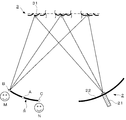
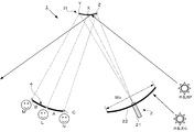
- FIG. 1 is a conceptual view of a first embodiment of the present invention.
- FIG. 8 is a conceptual diagram for explaining the operation at different positions in the first embodiment.
- Explanatory drawing of a light-shielding part Explanatory drawing of the light-shielding part in the different position of a crowd area.
- the conceptual diagram of the reflection part and light incident position seen from the center part of the audience area The conceptual diagram of the reflection part and light incident position seen from one end part of the audience area.
- Explanatory drawing of the effect of this invention Explanatory drawing of the specific parameter of the Example of this invention.
- the conceptual diagram of a 2nd Example The conceptual diagram of a 3rd Example.
- Explanatory drawing of the light-shielding part in the different position of the audience area in 3rd Example The conceptual diagram of a 4th Example. Explanatory drawing of the light-shielding part and partial area
- a projection system 1 comprises a projection device 2 for projecting an image or video (hereinafter simply referred to as an image) and a screen 3 onto which the image is projected.
- the projection device 2 includes a light source unit 21 and a light shielding unit 22 extended around the light source unit 21.
- the screen 3 is composed of a screen in which a plurality of optical elements 31 are arranged in the vertical and horizontal directions.
- the screens 3 in the present invention do not necessarily have to be aligned in one direction with the optical elements 31, and may be arranged so as to spread in a plane.
- the optical element 31 mentioned here is a member that changes the traveling direction of the light beam by an optical action such as reflection or tropism, and is made of, for example, a concave or convex reflector, or a translucent material.
- An optical lens or the like can be used.
- the first embodiment shown in FIG. 1 shows an embodiment in which a reflector is used as the optical element 31, and the reflector is configured by a screen provided in parallel in the vertical and horizontal directions.
- the individual reflectors differ in the form of the optical element 31 such as shape and inclination depending on the installation location, and change the traveling direction of the light beam from the light source unit 21.
- an audience area 4 for accommodating an audience who visually recognizes an image projected on the screen 3 is provided to face the screen 3, and the light source section whose optical path is changed by the optical element 31. Rays from 21 are directed to any particular location in this audience area 4. Then, the light from the light source unit 21 of the projection device 2 is projected onto the entire area of the screen 3 and is reflected by the plurality of optical elements 31 constituting the screen 3.
- the reflected light from the optical element 31 is irradiated to a specific position (for example, the position A in FIG. 1) in the audience area 4.
- a specific position for example, the position A in FIG. 1
- the audience L at the position A can visually recognize the image projected on the entire area of the screen 3.
- FIG. 2 illustrates ray trajectories in the case where the spectator M is located at one end (the left end in FIG. 2) in the audience area 4.
- the light projected from the light source unit 21 is reflected by each of the optical elements 31 of the screen 3, and each reflected light from each of the optical elements 31 is the position B of the audience area 4 Irradiated.
- the light incident positions of the corresponding optical elements 31 are different between the position A and the position B of the audience area.
- each optical element 31 As described above, the light reflected from each optical element 31 is directed to different observation positions (position A, position B) in the audience area 4 by the light incident position (reflection position) to each optical element 31 Therefore, even if the spectator position in the audience area 4 changes, the image or video projected on the screen 3 can be visually recognized.
- FIG. 3A conceptually shows a relationship in the case where an arbitrary optical element 31 in the screen 3 is taken out and this optical element 31 is observed from a position A at the center of the audience area 4.
- a light beam directed from the light source unit 21 to the position A via the optical element 31 is a light beam that has entered the position X of the optical element 31 and is reflected here. That is, at the position A of the audience area 4, the reflected light from the position X of the optical element 31 can be observed.
- the position Y and the position Z of the optical element 31 have a correspondence relationship in which the light shielding portion 22 is reflected.
- FIG. 3B shows the relationship of the light incident position (bright point 5) in the optical element 31 that can be viewed from the audience L at the center position A. In this case, the projection range (width of the light shielding portion 22) The bright point 5 is visually recognized at the central portion in Wx).
- FIG. 4A shows, in the conceptual diagram shown in FIG. 3, the relationship when the position to be observed (the position of the spectator) is changed. That is, when one end (left end) of the audience area 4 is the position B and the other end (right end) is the position C, the case where the optical element 31 is observed at each position is illustrated.
- the optical element 31 is viewed from the position B at the left end, the light incident position from the light source unit 21 is reflected as a bright spot at the position Y of the optical element 31 (the left end region of the optical element 31 in FIG.
- the light shielding portion 22 is reflected at the other positions X and Z.
- the light incident position from the light source unit 21 is reflected as a bright spot at the position Z of the optical element 31 (right end region of the optical element in FIG.
- the light shielding portion 22 is reflected at positions X and Y other than the above. That is, in the position B and the position C, the area of the projection range to be reflected on the optical element 31 is partially different. Therefore, when the audience area 4 is large, when viewing the optical element 31 from each observation position (A, B, C), the projection range or the light source unit is configured so that only the light source unit 21 and the light shielding unit 22 within the projection range are reflected. It is necessary to set 21 positions.
- the light incident position (reflection position) of the optical element 31 may be different depending on the observation position (A, B, C) of the audience area 4, the projection range (Wx) which is the width of the light shielding portion 22 in the audience area 4 The disturbance light does not enter the audience area 4 because the correspondence relationship is reflected in the optical element 31 only).
- the relationship of the light-incident position (bright point 5) in the optical element 31 which can be visually recognized from each audience B and C to FIG. 4 (B) (C) is shown.
- the size of the optical element 31 is very small, even if the observation position in the audience area 4 changes, the displacement of the light incident position (the position of the bright spot 5) in the optical element 31 can hardly be visually recognized. There is no problem in viewing the
- 5 to 7 show conceptual diagrams in the case where a plurality of optical elements 31 described in FIGS. 3 and 4 are arrayed vertically and horizontally to constitute a screen.
- 5 to 7 show an example of a screen in which eight optical elements 31 are arranged in each of the vertical direction and the horizontal direction.
- the actual arrangement is The number is an array of several thousands by several thousands.
- FIG. 5 is a conceptual view of the screen 3 viewed from the spectator L at the center position (A) of the audience area 4, and projection light is projected onto the screen 3 from the projection apparatus over the entire area.
- the light from the light source unit of the projection device is projected on the central position X on each optical element 31 of the screen 3 as shown in FIG. 3B, and a bright spot 5 is formed at the position X.
- the audience A can visually recognize the image projected on the screen 3.
- FIG. 6 and 7 show the case where the spectator position moves in the audience area 4, and FIG. 6 shows the case where the audience M is at the left end of the audience area 4, and FIG. 7 shows the audience N at the right end.
- the case is shown.
- the light incident position (reflection position) formed on each optical element 31 of the screen 3 changes, and the bright spot 5 also moves accordingly.
- the light projected onto the entire area of the screen 3 is reflected by each of the optical elements 31 and different observation positions A to C in the audience area 4 depending on the reflection positions in the optical element 31 (light incident positions from the light source unit).
- each optical element light beams are directed to different specific positions in the audience area depending on the light incident position from the light source unit. Further, this optical element guides the light beam to a specific position, and other than that, it has a correspondence relationship in which only the light shielding portion is reflected, and disturbance light does not enter.
- Each optical element 31 provided on the screen 3 has a configuration in which a projection range (Wx) which is the width of the light shielding portion 22 of the projection device 2 is reflected in the spectator area 4. Therefore, even if the light P in the area out of the projection range (Wx) is reflected by the optical element 31, it travels out of the audience area 4 and is not irradiated into the audience area 4.
- the light Q in the region inside the projection range (Wx) is originally blocked by the light shielding portion 22, and therefore does not reach the screen 3 and is not irradiated into the audience region 4.
- the projection system according to the present invention can project an image on a screen without being affected by disturbance light, and for example, can project an image with high contrast even in an environment with strong disturbance light such as outdoors. It becomes possible.
- the width of the optical element may be designed to be several mm to several ⁇ m, in which case it can be a screen on which fine three-dimensional patterns are arranged.
- the width of the optical element is appropriately set according to the required resolution, the distance between the screen and the audience area, and the like.
- FIG. 9 shows the parameters associated with an embodiment of the present invention, and the following is one numerical example of the entire projection system of the present invention.
- the vertical direction of the screen also follows the above design.
- the tilt ( ⁇ ) of the optical element at the screen end where the tilt angle [°] of the optical element is the largest with respect to the reference axis of the optical element at the center of the screen can be calculated by the following formula.
- the other optical elements can be calculated by substituting the separation distance from the center position of the screen into a calculation formula.
- the optical element 31 constituting the screen 3 has been described as a convex reflector, but it is not limited to this shape.
- the optical element 31 may have a correspondence relationship in which only within the set projection range (the installation range of the light source unit 21 and the light shielding unit 22) is reflected at each observation (spectator) position in the audience area 4, for example
- the shape may be concave or flat.
- the shape in which the convex optical element (FIG. 10A) shown in the embodiment following FIG. 1 is divided into two at the central portion and joined on the opposite side. (FIG. 10 (B)) can also be used.
- the optical path from the light source unit 21 of the projector 2 through the optical element 31 to the spectator M in the audience area 4 in this embodiment is shown in FIG.
- the shape of the screen 3 is not required to be flat, and may be a curved shape, or may be a three-dimensional screen in which the screens are circumferentially arranged.
- the projection range (Wx) configured by the light source unit and the light shielding unit is not limited in the form of arrangement, and various arrangements can be adopted.
- the shape and size of the reflector may be set arbitrarily with reference to the above-mentioned calculation formula, taking into consideration the configuration of the projection apparatus, the configuration of the screen, and the configuration of the audience area, and designing based on the geometrical relationship. Good.
- the audience area is assumed to be a plurality of spectators, but it is not limited to this, even if it is a projection system for one person (designing a narrow audience area) I do not care.
- FIG. 11 shows a third embodiment in which the optical element 31 is an optical lens.
- the projection device 2 is provided on the back side (upper side in FIG. 11) of the screen 3.
- the light projected from the projection device 2 to the back side of the screen 3 is incident on the position D or the position E of the optical lens (optical element) 31, is transmitted through the optical lens 31 and is bent.
- the light is collected at the observation position C and the observation position B. Thereby, the audience M and the audience N can respectively recognize the image projected on the screen 3.
- each optical lens 31 arranged on the screen 3 can observe an image at each position in the audience area 4 by directing light at different light incident positions to each audience position. .
- FIG. 12 illustrates the case where the optical lens (optical element) 31 is observed at positions B at one end of the audience area 4 and at positions C at the other end in the conceptual view shown in FIG. .
- the optical lens 31 is viewed from the position B at the left end, the light incident position from the light source unit 21 is the position D of the optical element 31 and is reflected as a bright spot in the right end region of the optical lens 31 in FIG. Further, the other positions are in a relationship of reflecting the light shielding portion 22.
- the optical lens 31 is viewed from the position C at the right end, the light incident position from the light source unit 21 becomes the position E of the optical lens 31 and is reflected as a bright point in the left end region of the optical lens 31 in FIG.
- the other positions are in a relationship of reflecting the light shielding portion 22. That is, in the position B and the position C, the area of the projection range to be reflected on the optical lens 31 is partially different. As a result, the disturbance light may enter the crowded area 4 by having a correspondence relation that reflects only the light source part 21 and the light shielding part 22 within the projection area, regardless of the position within the crowded area 4 from which the optical lens 31 is viewed. Absent. When the audience area 4 is large, when viewing the optical lens 31 from each observation position, it is necessary to set the projection range and the position of the light source unit 21 so as to reflect only the light source unit 21 and the light shielding unit 22 within the projection range. is there.
- the light which is incident on the optical lens (optical element) 31 of the screen 3 from the area other than the light shielding portion 22 in the projection device 2 and is transmitted is emitted outside the audience area 3 without entering the audience area 4 Is easily understood in the light of the description of FIG.
- the light source unit 21 of the projection device 2 enters each optical lens 31 of the screen 3 and transmits it.
- All the light is emitted to any position in the audience area 4, while the light (disturbance light) which is incident on the optical lens 31 from the area other than the light shielding portion 22 and is transmitted is not irradiated to the audience area 4, A projection system 1 in which disturbance light is eliminated can be realized.
- the projection device in the projection system including the projection device and the screen, includes the light source unit and the light shielding unit extended around the light source unit, and the screen
- a plurality of optical elements for changing the traveling direction of the light beam from the light source are arranged in a matrix, and each of the optical elements has different specific positions in the audience area depending on the light incident position from the light source
- the light shielding portion is configured such that the entire area of each of the optical elements reflects only within the range of the light shielding portion from any position in the audience area.
- Light incident from the light source unit to the optical element of the screen is incident on any position of the audience area and is viewed by all the spectators in the audience area. Then, light incident on the light emitting element from the area other than the light shielding part of the projection device travels to a position out of the audience area, so it is not visually recognized by the audience as disturbance light, and the audience always has clear images Is visible.
- FIG. 13 shows the conceptual diagram, and a plurality (two in this example) of light source units 21 (211, 212) provided in the projection device 2 are provided within the range (light shielding range) of the light shielding unit 22. Form is shown.
- the light beams from the light source units 211 and 212 are directed by the respective optical elements 31 constituting the screen 3 to different specific partial areas H1 and H2 in the audience area 4, respectively.
- the partial areas H1 and H2 indicate partial areas partitioned in the audience area 4. Further, as described later, the partial regions H1 and H2 may be configured to overlap or be separated.
- FIG. 14 conceptually shows the relationship when an arbitrary optical element 31 in the screen 3 is taken out in the embodiment shown in FIG.
- a plurality of light source units 211 and 212 are provided in the range (light shielding range) of the light shielding unit 22, and in the audience area 4, the light source units 211 and 212 correspond to each other. Partial regions H1 and H2 are formed.
- the light projected from the plurality of light source units 211 and 212 is directed.
- expansion of the audience area can be easily performed without changing the design of the optical elements constituting the screen. It is also possible to realize high-intensity light projection by narrowly designing a partial area in the audience area.
- the optical units 211 and 212 may be configured to project the same image, but may be configured to project different images. For example, when different images are projected, partial regions H1 and H2 corresponding to the light source units 211 and 212 are irradiated with light from different light source units. That is, by making the image projected from the first light source unit 211 different from the image projected from the second light source unit 212, different images can be visually recognized in the partial regions H1 and H2 in the audience region 4 Therefore, the projection image can be changed depending on the observation place.
- FIG. 15 is a description of the light source unit 21 and the light shielding unit 22 at different positions in the audience area 4, in which the partial regions H 1 and H 2 corresponding to the light source units 211 and 212 are arranged in a row.
- FIG. 16 is a description of the light shielding portion 22 at each of the audience positions A to F in the case of the arrangement of FIG. 15, and from the observation positions (A to F) in the audience area 4 , 312) are conceptually shown.
- the optical element 31 is observed from the observation position A in the audience area 4, the range reflected in the optical element 31 is the positions a to c (range P) of the light shielding portion 22. As shown in FIG.
- the position c can be observed as a bright spot.
- the position c is reflected in the position Z of the optical element 31, and at the observation position A, the position Z of the optical element 31 is reflected as a bright spot.
- the range reflected in the optical element 31 is the positions b to d (range Q) of the light shielding portion 22.
- the position c can be observed as a bright spot.
- the position c is reflected in the position X of the optical element 31, and at the observation position B, the position X of the optical element 31 is reflected as a bright spot.
- the range of the light shielding portion reflected in the optical element is changed.
- the range reflected in the optical element 31 is the positions c to e (range R) of the light shielding portion 22.
- the position c can be observed as a bright spot.
- the position c is reflected in the position Y of the optical element 31, and at the observation position C, the position Z of the optical element 31 is reflected as a bright spot.
- the range reflected in the optical element 31 is the positions d to f (range S) of the light shielding portion 22.
- the first light source unit 211 is disposed at the position c
- the light from the first light source unit 211 disposed at the position c is confirmed from the observation position D because it is not reflected in the optical element 31 It is not possible.
- the other second light source unit 212 is disposed at the position f
- the position f can be observed as a bright spot.
- the position f is reflected in the position Z of the optical element 31, and at the observation position D, the position Z of the optical element 31 is reflected as a bright spot.
- the light from the corresponding light source units 211 and 212 can be observed in each of the partial regions H1 and H2.
- FIG. 17 illustrates the arrangement intervals of a plurality of light source units arranged in the range of the light shielding unit 22.
- Each light source unit (211, 212, 213, 214) has a corresponding light shielding range. Exists. This indicates the observation range of the light shielding part that can be observed from the partial area when the light beam from one light source part is directed to a specific partial area in the audience area by the optical element. The light blocking range specified depending on the part is different.
- FIG. 17A a plurality (three) of light source units 211 to 213 are shown, and the light source units 211 to 213 are arranged at predetermined intervals within the range of the light shielding unit 22.
- a plurality of (four) light source units 211 to 214 are arranged at predetermined intervals within the range of the light shielding unit 22, and two minutes of the light shielding range M specified by one light source unit.
- Each light source unit is disposed at an interval L2 smaller than 1 (an interval smaller than 1/2) (L2 ⁇ M / 2).
- L2 an interval smaller than 1/2
- L2 ⁇ M / 2 the partial areas in the audience area are arranged so as to overlap each other, so that the projected image can be projected within the audience area without interruption. For example, in the case where the spectators themselves observe different images while moving the viewpoint, there is an effect that the reflection (switching) of each image becomes smoother.
- the light source units 211 to 214 project different images
- different images are displayed in the partial areas in the audience area. Therefore, when the viewpoint is moved between the partial areas, the partial areas Since the image is visually recognized to switch before and after the boundary, there is a possibility that the viewer may feel discomfort. In such a case, by arranging the partial areas in the audience area to overlap, it is difficult to visually recognize the switching of the image between the partial areas, and the transition of the image is recognized more smoothly.
- a plurality of (three) light source units 11 to 213 are arranged at predetermined intervals within the range of the light shielding unit 22, and one half of the light shielding range specified by one light source unit.
- the light source units are arranged at an interval L3 (an interval larger than 1 ⁇ 2) larger than (L3> M / 2).
- L3 an interval larger than 1 ⁇ 2 larger than (L3> M / 2).
- FIG. 18 conceptually illustrates an embodiment in which a plurality of light source units (211 to 215) are disposed within the range of the light shielding unit 22 and different parallax images (P211 to P215) are projected on the respective light source units. It is a thing.
- a plurality of partial areas (H1 to H5) are formed in the audience area 4 corresponding to the respective light source units (211 to 215), and different parallax images are respectively generated in the respective partial areas (H1 to H5). It is projected. Such a configuration enables three-dimensional display.
- FIG. 19 illustrates an embodiment of a projection system capable of stereoscopic display according to the present invention.
- This embodiment shows a configuration for personal projection that has two light source units 211 and 212 for projecting parallax images, and allows a single audience located at the center of the screen 3 to visually recognize stereoscopic display. Specific numerical examples are shown below.
- the light shielding portion is formed around the light source portion, and the mixture of disturbance light and stray light can be prevented in the audience area, and for example, even in a bright environment such as outdoor.
- a clear three-dimensional image can be projected.
- by increasing the number of light source units it is possible to project many parallax images, and to enable stereoscopic vision with a sense of reality.
- the change in the image when the viewpoint is moved becomes smoother, and a more realistic stereoscopic image can be displayed.
- the change in the image when the viewpoint is moved becomes smoother, and a more realistic stereoscopic image can be displayed.
- a more realistic stereoscopic image can be displayed.
- by narrowing the interval between the partial areas to about the interval between the right eye and the left eye different parallax images can be visually recognized by the right eye and the left eye, enabling stereoscopic vision with binocular parallax, and moving the viewpoint It is also possible to perceive changes in the image due to motion parallax, and stereoscopic display with more realism becomes possible.
- the distance between partial regions is designed to be narrow enough to allow a plurality of parallax images to simultaneously enter one eye, as in the case of focusing on a solid object that actually exists. This makes it possible to perceive a stereoscopic image more naturally.
- the light source units so that the partial regions overlap, it is possible to project a plurality of parallax images at a specific position, and by projecting a plurality of parallax images in one eye, it is more natural. It is also possible to enable three-dimensional display.
- the shape of the screen according to the present invention is not limited to a flat surface, and for example, various shapes such as a curved shape, a pillar shape (cylindrical shape), etc. can be adopted, and a dome shape covering part or all of the field of view It does not matter.
- the optical element may have any shape as long as it can direct the light beam projected from the light source unit to an arbitrary partial area.
- a circular shape, an elliptical shape, a polygonal shape or the like can be adopted depending on the partial region set arbitrarily, and the screen is configured by arranging these optical elements in the vertical and horizontal directions.
- Projection system 2 Projection device 21: Light source part 211-215: Each light source part 22: Light shielding part 3: Screen 31: Optical element 4: Audience area 5: Bright point (light incident position) M: Light blocking range H: Partial area
Landscapes
- Physics & Mathematics (AREA)
- General Physics & Mathematics (AREA)
- Optics & Photonics (AREA)
- Engineering & Computer Science (AREA)
- Multimedia (AREA)
- Signal Processing (AREA)
- Projection Apparatus (AREA)
- Overhead Projectors And Projection Screens (AREA)
- Transforming Electric Information Into Light Information (AREA)
Abstract
【課題】画像を投影する投影装置と、その画像が投影されるスクリーンとを備えた投影システムにおいて、種々の要因で変化する外乱光を排除することが可能な新規な投影システムを提供することである。 【解決手段】前記投影装置は、光源部と、当該光源部の周囲に延設された遮光部とを備え、前記スクリーンは、前記光源部からの光線の進行方向を変化させる光学素子が縦横に複数配列されており、前記各光学素子は、前記光源部からの光入射位置によって、それぞれ観衆領域内の異なる特定の位置に光線を指向させるとともに、前記遮光部は、前記観衆領域内のいずれの位置からみても、前記各光学素子の全域が、当該遮光部の範囲内のみを映し込むように構成されていることを特徴とする。
Description
この発明は、投影装置からの光をスクリーンに画像投影する投影システムに関するものである。
近年、投影装置(プロジェクタ)を利用して大型スクリーンに画像投影することが日常的に行われている。この際、投影装置からの投射光は大型スクリーンで拡散反射されて画像や映像を映し出す構成が一般的である。
このような従来の投影方式では、スクリーンには投射光だけでなく外乱光(投影装置以外の外部からの光)も照射されるため、例えば明るい環境下では、投影画像のコントラストが低下し、スクリーン上の画像や映像が視認し難くなる、という問題がある。
このような問題に対して特開2010-96883号公報(特許文献1)では、スクリーン上に光吸収膜を設け、当該光吸収膜が外乱光に対応する領域上に形成されることで、外乱光の影響を抑制することが記載されている。
このような問題に対して特開2010-96883号公報(特許文献1)では、スクリーン上に光吸収膜を設け、当該光吸収膜が外乱光に対応する領域上に形成されることで、外乱光の影響を抑制することが記載されている。
しかしながら、特許文献1に記載の方法では、想定される特定の外乱光にしか対応できず、外乱光の向きが経時的に変化する場合や、別の外乱光が照射された際には十分に機能しないという問題がある。そのため、外乱光を排除する根本的な解決は未だ実現できていないというのが実情である。
この発明は、上記従来技術の問題点に鑑みて、投影装置(プロジェクタ)を利用してスクリーンに画像投影する投影システムにおいて、種々の要因で変化する外乱光を排除することが可能な新規の投影システムを提供するものである。
上記課題を解決するために、この発明に係わる投影システムでは、前記投影装置は、光源部と、当該光源部の周囲に延設された遮光部とを備え、前記スクリーンは、前記光源部からの光線の進行方向を変化させる光学素子が縦横に多数配列されており、前記各光学素子は、前記光源部からの光入射位置によって、それぞれ観衆領域内の異なる特定の位置に光線を指向させるとともに、前記遮光部は、前記観衆領域内のいずれの位置からみても、前記各光学素子の全域が、当該遮光部の範囲内のみを映し込むように構成されていることを特徴とする。
また、前記光学素子は、反射体で構成されていることが好ましい。
また、前記光学素子は、透光性の光学レンズで構成されていることが好ましい。
また、前記光学素子は、反射体で構成されていることが好ましい。
また、前記光学素子は、透光性の光学レンズで構成されていることが好ましい。
また光源部は、前記遮光部の範囲内に複数設けられ、各光源部からの光線は、前記光学素子によって、それぞれ観衆領域内の異なる特定の部分領域に指向されることを特徴としてもよい。
また、一つの光源部によって特定される遮光範囲の略1/2の間隔で、隣接する光源部が配置されていることが好ましい。
また、一つの光源部によって特定される遮光範囲の略1/2よりも小さい間隔で、隣接する光源部が配置されていることが好ましい。
また、一つの光源部によって特定される遮光範囲の略1/2よりも大きい間隔で、隣接する光源部が配置されていることが好ましい。
また、一つの光源部によって特定される遮光範囲の略1/2の間隔で、隣接する光源部が配置されていることが好ましい。
また、一つの光源部によって特定される遮光範囲の略1/2よりも小さい間隔で、隣接する光源部が配置されていることが好ましい。
また、一つの光源部によって特定される遮光範囲の略1/2よりも大きい間隔で、隣接する光源部が配置されていることが好ましい。
この発明によれば、投影装置とスクリーンを備えた投影システムにおいて、前記投影装置が、光源部と、当該光源部の周囲に延設された遮光部とを備え、前記スクリーンが、前記光源部からの光線の進行方向を変化させる光学素子が縦横に複数配列されており、前記遮光部は、前記観衆領域内のいずれの位置からみても、前記各光学素子の全域が、当該遮光部の範囲内のみを映し込むように構成されていることにより、前記投影装置の遮光部以外の領域から前記発光素子に入射する光は、観衆領域を外れた位置に進行するので、外乱光として観客に視認されることがなく、観客は常に明瞭な画像を視認することができる。
図1に本発明の第1の実施例が示されていて、投影システム1は、画像や映像(以下、単に画像という)を投影する投影装置2と、その画像が投影されるスクリーン3とを備えている。
前記投影装置2は、光源部21と、この光源部21の周囲に延設された遮光部22とからなる。
一方、前記スクリーン3は、複数の光学素子31が縦横に配列されたスクリーンで構成されている。なお、本発明におけるスクリーン3は、必ずしも光学素子31が一方向に整列されている必要はなく、面状に広がるよう配列されていればよい。
また、ここでいう光学素子31は、反射や屈性等の光学的作用により光線の進行方向を変化させる部材であり、例えば、凹状又は凸状の反射体や、透光性材料で構成された光学レンズ等を用いることができる。
前記投影装置2は、光源部21と、この光源部21の周囲に延設された遮光部22とからなる。
一方、前記スクリーン3は、複数の光学素子31が縦横に配列されたスクリーンで構成されている。なお、本発明におけるスクリーン3は、必ずしも光学素子31が一方向に整列されている必要はなく、面状に広がるよう配列されていればよい。
また、ここでいう光学素子31は、反射や屈性等の光学的作用により光線の進行方向を変化させる部材であり、例えば、凹状又は凸状の反射体や、透光性材料で構成された光学レンズ等を用いることができる。
図1の第1の実施例では、光学素子31として反射体を用いた実施形態を示しており、反射体が縦横に並設されたスクリーンで構成されている。個々の反射体は、設置箇所によって形状や傾きといった光学素子31の形態が異なっていて、前記光源部21からの光線の進行方向を変化させる。
また、前記スクリーン3に対面するように、該スクリーン3上に投影された画像を視認する観客が収容される観衆領域4が設けられており、前記光学素子31によって光路を変更された前記光源部21からの光線は、この観衆領域4のいずれかの特定の位置に照射される。
そして、投影装置2の光源部21からの光は、前記スクリーン3の全域に投射され、スクリーン3を構成する複数の光学素子31によって反射される。そして、各光学素子31における光源部21からの光入射位置によって、前記光学素子31からの反射光は、観衆領域4内の特定の位置(例えば、図1の位置A)に照射される。これにより、位置Aの観客Lは、スクリーン3全域に投影された画像を視認することができる。
また、前記スクリーン3に対面するように、該スクリーン3上に投影された画像を視認する観客が収容される観衆領域4が設けられており、前記光学素子31によって光路を変更された前記光源部21からの光線は、この観衆領域4のいずれかの特定の位置に照射される。
そして、投影装置2の光源部21からの光は、前記スクリーン3の全域に投射され、スクリーン3を構成する複数の光学素子31によって反射される。そして、各光学素子31における光源部21からの光入射位置によって、前記光学素子31からの反射光は、観衆領域4内の特定の位置(例えば、図1の位置A)に照射される。これにより、位置Aの観客Lは、スクリーン3全域に投影された画像を視認することができる。
図2には、観衆領域4において、観客Mが一方の端部(図2で左端部)に位置している場合の光線軌跡が説明されている。この位置Bには、位置Aと同様に、光源部21から投射された光がスクリーン3の各光学素子31で反射され、この各光学素子31からのそれぞれの反射光が観衆領域4の位置Bに照射される。
このとき、観衆領域の位置Aと位置Bとでは、対応する各光学素子31の光入射位置がそれぞれ異なっている。このように、各光学素子31からの反射光は、各光学素子31への光入射位置(反射位置)によって、観衆領域4内の異なる観測位置(位置A、位置B)に光線が指向されるため、観衆領域4内の観客位置が変わっても、スクリーン3に投影された画像や映像を視認することができる。
このとき、観衆領域の位置Aと位置Bとでは、対応する各光学素子31の光入射位置がそれぞれ異なっている。このように、各光学素子31からの反射光は、各光学素子31への光入射位置(反射位置)によって、観衆領域4内の異なる観測位置(位置A、位置B)に光線が指向されるため、観衆領域4内の観客位置が変わっても、スクリーン3に投影された画像や映像を視認することができる。
なお、図2において、観客Nが観衆領域4における他端部(図2で右端部)(位置C)に位置している場合にも、煩雑を避ける意味で光線軌跡は図示されていないが、同様に光源部21からの光は光学素子31の更に異なる光入射位置に入射され、ここで反射されて観衆領域4の位置Cに指向されていき、位置Cにいる観客Nは、スクリーン3に投影された画像を視認することができる。
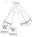
図3(A)は、スクリーン3内の任意の光学素子31を取り出し、この光学素子31を、観衆領域4の中央の位置Aから観測した場合の関係を概念的に示したものである。
光源部21から前記光学素子31を介して位置Aに指向される光線は、当該光学素子31の位置Xに入射し、ここで反射した光線である。つまり観衆領域4の位置Aでは、光学素子31の位置Xからの反射光が観測できる。また光学素子31の位置Y及び位置Zは、それぞれ遮光部22が映り込む対応関係となっている。よって位置Y及び位置Zには位置Aに向かう反射光線がないため、位置Aでは位置Y及び位置Zからの光は観測できない。そのため位置Aの観客Lからは、光学素子の位置Xからの反射光線のみが輝点5として観測される。
図3(B)に中央の位置Aの観客Lから視認できる光学素子31内の光入射位置(輝点5)の関係を示していて、この場合は、遮光部22の幅である投影範囲(Wx)において中央部に輝点5が視認される。
光源部21から前記光学素子31を介して位置Aに指向される光線は、当該光学素子31の位置Xに入射し、ここで反射した光線である。つまり観衆領域4の位置Aでは、光学素子31の位置Xからの反射光が観測できる。また光学素子31の位置Y及び位置Zは、それぞれ遮光部22が映り込む対応関係となっている。よって位置Y及び位置Zには位置Aに向かう反射光線がないため、位置Aでは位置Y及び位置Zからの光は観測できない。そのため位置Aの観客Lからは、光学素子の位置Xからの反射光線のみが輝点5として観測される。
図3(B)に中央の位置Aの観客Lから視認できる光学素子31内の光入射位置(輝点5)の関係を示していて、この場合は、遮光部22の幅である投影範囲(Wx)において中央部に輝点5が視認される。
図4(A)は、図3に示す概念図において、観測する位置(観客位置)を変えた場合の関係が示されている。
つまり、観衆領域4の一端(左端)を位置B、他端(右端)を位置Cとした場合、それぞれの位置で光学素子31を観測した場合が図示されている。
左端の位置Bから光学素子31をみた場合、光源部21からの光入射位置は光学素子31の位置Y(図4(A)における光学素子31の左側端部領域)に輝点として映り込み、それ以外の位置Xや位置Zには遮光部22が映り込む関係となる。
また右端の位置Cから光学素子31をみた場合、光源部21からの光入射位置は、光学素子31の位置Z(図4(A)における光学素子の右側端部領域)に輝点として映り込み、それ以外の位置X、位置Yには遮光部22が映り込む関係となる。つまり位置Bと位置Cとでは、光学素子31に映り込む投影範囲の領域が部分的に異なることになる。そのため、観衆領域4が大きい場合は、各観測位置(A、B、C)から光学素子31をみたとき、投影範囲内の光源部21と遮光部22のみが映り込むよう、投影範囲や光源部21の位置を設定する必要がある。
つまり、観衆領域4の一端(左端)を位置B、他端(右端)を位置Cとした場合、それぞれの位置で光学素子31を観測した場合が図示されている。
左端の位置Bから光学素子31をみた場合、光源部21からの光入射位置は光学素子31の位置Y(図4(A)における光学素子31の左側端部領域)に輝点として映り込み、それ以外の位置Xや位置Zには遮光部22が映り込む関係となる。
また右端の位置Cから光学素子31をみた場合、光源部21からの光入射位置は、光学素子31の位置Z(図4(A)における光学素子の右側端部領域)に輝点として映り込み、それ以外の位置X、位置Yには遮光部22が映り込む関係となる。つまり位置Bと位置Cとでは、光学素子31に映り込む投影範囲の領域が部分的に異なることになる。そのため、観衆領域4が大きい場合は、各観測位置(A、B、C)から光学素子31をみたとき、投影範囲内の光源部21と遮光部22のみが映り込むよう、投影範囲や光源部21の位置を設定する必要がある。
このように観衆領域4の観測位置(A、B、C)によって光学素子31の光入射位置(反射位置)が異なってみえるものの、観衆領域4内では遮光部22の幅である投影範囲(Wx)のみが光学素子31に映り込む対応関係となることで、観衆領域4内に外乱光が入り込むことがない。
図4(B)(C)に、ぞれぞれの観客B、Cから視認できる光学素子31内の光入射位置(輝点5)の関係を示している。
尚、光学素子31のサイズが非常に小さい場合は、観衆領域4内の観測位置が変わっても光学素子31内の光入射位置(輝点5の位置)のズレは殆ど視認できないため、投影画像の閲覧に支障がでることはない。
図4(B)(C)に、ぞれぞれの観客B、Cから視認できる光学素子31内の光入射位置(輝点5)の関係を示している。
尚、光学素子31のサイズが非常に小さい場合は、観衆領域4内の観測位置が変わっても光学素子31内の光入射位置(輝点5の位置)のズレは殆ど視認できないため、投影画像の閲覧に支障がでることはない。
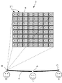
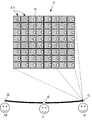
図5~7には、図3、4で説明した光学素子31を、縦横に複数配列してスクリーンを構成した場合の概念図が示されている。
なお、図5~7においては、光学素子31を縦方向、横方向ともに8個ずつ配列したスクリーン例が示されているが、スクリーンの大きさにもよるが、解像度の見地から、実際の配置数は数千個×数千個といったレベルでの配列となる。
なお、図5~7においては、光学素子31を縦方向、横方向ともに8個ずつ配列したスクリーン例が示されているが、スクリーンの大きさにもよるが、解像度の見地から、実際の配置数は数千個×数千個といったレベルでの配列となる。
図5では、観衆領域4の中央の位置(A)の観客Lからスクリーン3を見た場合の概念図であり、前記スクリーン3にはその全域に投影装置から投射光が投影されている。投影装置の光源部からの光は、スクリーン3の各光学素子31には、前記図3(B)に示すように中央の位置Xに投影されて、当該位置Xに輝点5が形成され、これにより観客Aは、前記スクリーン3に投影される画像を視認することができる。
図6および図7は、観衆領域4内において、観客位置が移動した場合であって、図6は観衆領域4の左端部に観客Mがいる場合で、図7は右端部に観客Nがいる場合を示している。このように観客位置が変わった場合、前記スクリーン3の各光学素子31に形成される光入射位置(反射位置)が変化し、これに伴い輝点5も移動する。
しかし、スクリーン3全域に投影された光は、各光学素子31で反射され、当該光学素子31内の反射位置(光源部からの光入射位置)によってそれぞれ観衆領域4内の異なる観測位置A~C(観客L~N)に光線が導かれることにより、異なる観測位置からでも同等の画像を視認することが可能となる。
上述のとおり、各光学素子は、光源部からの光入射位置によって、それぞれ観衆領域内の異なる特定の位置に光線が指向される。またこの光学素子は、特定の位置に対して光線を導くと共に、それ以外は遮光部のみを映し込む対応関係となっており、外乱光が入り込むことが無くなる。
しかし、スクリーン3全域に投影された光は、各光学素子31で反射され、当該光学素子31内の反射位置(光源部からの光入射位置)によってそれぞれ観衆領域4内の異なる観測位置A~C(観客L~N)に光線が導かれることにより、異なる観測位置からでも同等の画像を視認することが可能となる。
上述のとおり、各光学素子は、光源部からの光入射位置によって、それぞれ観衆領域内の異なる特定の位置に光線が指向される。またこの光学素子は、特定の位置に対して光線を導くと共に、それ以外は遮光部のみを映し込む対応関係となっており、外乱光が入り込むことが無くなる。
なお、投射光の投影領域内において、スクリーンを構成する光学素子の設置個数を増やすことで解像度を高めることが可能であることは前述したとおりである。また光学素子の設置個数が増大するにつれて、図5~図7に示す反射地点(輝点)の変動は殆ど認識されなくなり、投影装置からの映像が観客領域で適切に視認されることが理解できる。
次いで、本発明の投影システムにより外乱光の影響が抑えられる理由について図8に基づいて説明すると以下のとおりである。
スクリーン3に設けられた各光学素子31は、投影装置2の遮光部22の幅である投影範囲(Wx)が観客領域4に映り込む構成となっている。そのため投影範囲(Wx)から外れた領域の光Pは、光学素子31で反射されても、観衆領域4を外れたところに進行し、観衆領域4内に照射されることがない。また投影範囲(Wx)の内側の領域の光Qは、もともと遮光部22によって光が遮られるため、スクリーン3に到達することがなく、観衆領域4内には照射されない。このように、観衆領域4内に外乱光が入り込まないため、スクリーン上の外乱光を視認することがない。
以上の構成により、本発明が示す投影システムは、外乱光の影響を受けずに、スクリーンに画像投影することが可能となり、例えば屋外などの外乱光が強い環境下においてもコントラストの高い画像投影が可能となる。
スクリーン3に設けられた各光学素子31は、投影装置2の遮光部22の幅である投影範囲(Wx)が観客領域4に映り込む構成となっている。そのため投影範囲(Wx)から外れた領域の光Pは、光学素子31で反射されても、観衆領域4を外れたところに進行し、観衆領域4内に照射されることがない。また投影範囲(Wx)の内側の領域の光Qは、もともと遮光部22によって光が遮られるため、スクリーン3に到達することがなく、観衆領域4内には照射されない。このように、観衆領域4内に外乱光が入り込まないため、スクリーン上の外乱光を視認することがない。
以上の構成により、本発明が示す投影システムは、外乱光の影響を受けずに、スクリーンに画像投影することが可能となり、例えば屋外などの外乱光が強い環境下においてもコントラストの高い画像投影が可能となる。
本発明に係るスクリーンは、複数の光学素子を個々に決められた条件で配置させる必要がある。また解像度を高めるために、光学素子の幅を数mm~数μmに設計してもよく、その場合は、微細な三次元パターンが配列されたスクリーンとすることができる。このように、必要とされる解像度と、スクリーンと観衆領域との離間距離等によって、光学素子の幅が適宜設定される。
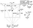
図9は、本発明の実施例に関連するパラメータを示しており、以下、本発明の投影システム全体の一数値例を挙げると以下のとおりである。
・スクリーン幅(Ws):1000mm
・スクリーン~投影装置間距離(Dsp):2000mm
・観衆領域幅(We):3000mm
・スクリーン~観衆領域間距離(Dse):5000mm
・光学素子の幅(Wm):1mm
・光学素子の形状:凸形状
なお、スクリーンの縦方向も上記設計に従う。
・スクリーン幅(Ws):1000mm
・スクリーン~投影装置間距離(Dsp):2000mm
・観衆領域幅(We):3000mm
・スクリーン~観衆領域間距離(Dse):5000mm
・光学素子の幅(Wm):1mm
・光学素子の形状:凸形状
なお、スクリーンの縦方向も上記設計に従う。
・スクリーン中心の光学素子の曲率半径(R)は、下記の計算式による算出することができる。
曲率半径(R)=1/(arctan(We/Wse))
=1/(arctan(3000/5000))=1.85mm
・スクリーン中心の光学素子の基準軸に対して、光学素子の傾き角度[°]が最も大きくなるスクリーン端部の光学素子の傾き(θ)は、下記の計算式により算出できる。尚、その他の光学素子については、スクリーンの中心位置からの離間距離を算出式に代入することで算出可能である。
傾き(θ)=arctan((Ws/2)/Wse)
=arctan(500/5000)=5.7[°]
・必要とされる遮光部の幅(Wx)は、下記の計算式により算出できる。
Wx=2×Dsp×tan(2θ)
=2×2000[mm]×tan(11.4[°])=810mm以上
曲率半径(R)=1/(arctan(We/Wse))
=1/(arctan(3000/5000))=1.85mm
・スクリーン中心の光学素子の基準軸に対して、光学素子の傾き角度[°]が最も大きくなるスクリーン端部の光学素子の傾き(θ)は、下記の計算式により算出できる。尚、その他の光学素子については、スクリーンの中心位置からの離間距離を算出式に代入することで算出可能である。
傾き(θ)=arctan((Ws/2)/Wse)
=arctan(500/5000)=5.7[°]
・必要とされる遮光部の幅(Wx)は、下記の計算式により算出できる。
Wx=2×Dsp×tan(2θ)
=2×2000[mm]×tan(11.4[°])=810mm以上
以上説明した実施例においては、スクリーン3を構成する光学素子31は凸面形状の反射体として説明していたが、この形状に限定されるものではない。この光学素子31は、設定された投影範囲(光源部21と遮光部22の設置範囲)内のみを観衆領域4の各観測(観客)位置に映し込む対応関係を有する構成であればよく、例えば、凹面形状であってもよく、平板形状であってもよい。
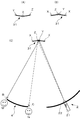
また、図10に示す第2の実施例のように、図1以下の実施例で示した凸形状光学素子(図10(A))を中央部で2分割して反対側に繋ぎ合わせた形状(図10(B))とすることもできる。
この実施例での、投影装置2の光源部21から光学素子31を経て観衆領域4内の観客Mに至る光路が図10(C)に示されている。
また、スクリーン3の形状も平面状である必要はなく、曲面形状であっても構わないし、スクリーンが円周状に配置された立体型のスクリーンであっても構わない。
この実施例での、投影装置2の光源部21から光学素子31を経て観衆領域4内の観客Mに至る光路が図10(C)に示されている。
また、スクリーン3の形状も平面状である必要はなく、曲面形状であっても構わないし、スクリーンが円周状に配置された立体型のスクリーンであっても構わない。
また、投影装置内に光源部は一つのみ形成されたものが説明されていたが、光源部は複数台であっても何ら問題はない。光源部と遮光部とで構成される投影範囲(Wx)は、配置形態に制約はなく様々な配置が採用できる。また反射体の形状やサイズは上述の計算式を参考として任意に設定してよく、投影装置の構成とスクリーンの構成、観衆領域の構成を加味し、幾何学的な関係に基づいて設計すればよい。
また本発明に記載の実施形態では、観衆領域は複数の観客を想定したものとなっているが、これに限定されるものではなく一人用(観衆領域が狭い設計)の投影システムであっても構わない。
また本発明に記載の実施形態では、観衆領域は複数の観客を想定したものとなっているが、これに限定されるものではなく一人用(観衆領域が狭い設計)の投影システムであっても構わない。
更には、以上の実施例では、光学素子31を反射体としたものであるが、透過型の光学レンズであってもよい。
図11には、光学素子31が光学レンズである第3の実施例が示されている。この実施例では、投影装置2は、スクリーン3の裏側(図11中では上部側)に設けられている。該投影装置2からスクリーン3の裏側に投影された光は、それぞれ光学レンズ(光学素子)31の位置Dや位置Eに入射し、該光学レンズ31を透過し屈曲されて、観客領域4内の観測位置Cや観測位置Bに集光される。これにより、観客Mや観客Nはそれぞれスクリーン3に投影された画像を認識することが出来る。
図11には、光学素子31が光学レンズである第3の実施例が示されている。この実施例では、投影装置2は、スクリーン3の裏側(図11中では上部側)に設けられている。該投影装置2からスクリーン3の裏側に投影された光は、それぞれ光学レンズ(光学素子)31の位置Dや位置Eに入射し、該光学レンズ31を透過し屈曲されて、観客領域4内の観測位置Cや観測位置Bに集光される。これにより、観客Mや観客Nはそれぞれスクリーン3に投影された画像を認識することが出来る。
ここで観測位置Cには光学レンズ(光学素子)31の光入射位置Eからの光線が指向され、観測位置Bには光学レンズ31の光入射位置Dからの光線が指向される。ここで光入射位置とは、単体の光学レンズ31における入射面上の任意の位置を指すものである。上記構成により、スクリーン3上に配列された各光学レンズ31は、それぞれ異なる光入射位置の光が各観客位置に指向されることにより、観衆領域4内の各位置で画像を観測することができる。
図12は、図11に示す概念図において、観衆領域4の一端にある位置Bと、他端にある位置Cのそれぞれの位置で光学レンズ(光学素子)31を観測した場合が図示されている。
左端の位置Bから光学レンズ31をみた場合、光源部21からの光入射位置は光学素子31の位置Dとなり、図12における光学レンズ31の右側端部領域に輝点として映り込む。またそれ以外の位置は遮光部22を映し込む関係となる。
一方、右端の位置Cから光学レンズ31をみた場合、光源部21からの光入射位置は光学レンズ31の位置Eとなり、図12における光学レンズ31の左側端部領域に輝点として映り込む。またそれ以外の位置は遮光部22を映し込む関係となる。つまり位置Bと位置Cとでは、光学レンズ31に映り込む投影範囲の領域が部分的に異なることになる。これにより観衆領域4内のどの位置から光学レンズ31をみても、投影領域内の光源部21と遮光部22のみを映し込む対応関係となることで、観衆領域4内に外乱光が入り込むことがない。
また観衆領域4が大きい場合は、各観測位置から光学レンズ31をみたとき、投影範囲内の光源部21と遮光部22のみを映し込むよう、投影範囲や光源部21の位置を設定する必要がある。
左端の位置Bから光学レンズ31をみた場合、光源部21からの光入射位置は光学素子31の位置Dとなり、図12における光学レンズ31の右側端部領域に輝点として映り込む。またそれ以外の位置は遮光部22を映し込む関係となる。
一方、右端の位置Cから光学レンズ31をみた場合、光源部21からの光入射位置は光学レンズ31の位置Eとなり、図12における光学レンズ31の左側端部領域に輝点として映り込む。またそれ以外の位置は遮光部22を映し込む関係となる。つまり位置Bと位置Cとでは、光学レンズ31に映り込む投影範囲の領域が部分的に異なることになる。これにより観衆領域4内のどの位置から光学レンズ31をみても、投影領域内の光源部21と遮光部22のみを映し込む対応関係となることで、観衆領域4内に外乱光が入り込むことがない。
また観衆領域4が大きい場合は、各観測位置から光学レンズ31をみたとき、投影範囲内の光源部21と遮光部22のみを映し込むよう、投影範囲や光源部21の位置を設定する必要がある。
ここで、投影装置2における遮光部22以外の領域からスクリーン3の光学レンズ(光学素子)31に入射され透過する光は、観衆領域4に入射することなく、観衆領域3以外に出射されることは、図8の説明に照らして容易に理解される。
このような光学レンズ31を縦横に配列させたスクリーン3を用い、本発明に係る装置構成とすることで、投影装置2の光源部21からスクリーン3の各光学レンズ31に入射しこれを透過する光は、すべて観衆領域4のいずれかの位置に照射され、一方、遮光部22以外の領域から光学レンズ31に入射し透過する光(外乱光)は観衆領域4に照射されることがなく、外乱光を排除した投影システム1が実現できる。
このような光学レンズ31を縦横に配列させたスクリーン3を用い、本発明に係る装置構成とすることで、投影装置2の光源部21からスクリーン3の各光学レンズ31に入射しこれを透過する光は、すべて観衆領域4のいずれかの位置に照射され、一方、遮光部22以外の領域から光学レンズ31に入射し透過する光(外乱光)は観衆領域4に照射されることがなく、外乱光を排除した投影システム1が実現できる。
以上説明したように、この発明によれば、投影装置とスクリーンを備えた投影システムにおいて、前記投影装置が、光源部と、当該光源部の周囲に延設された遮光部とを備え、前記スクリーンが、前記光源部からの光線の進行方向を変化させる光学素子が縦横に複数配列されており、前記各光学素子は、前記光源部からの光入射位置によって、それぞれ観衆領域内の異なる特定の位置に光線を指向させるとともに、前記遮光部は、前記観衆領域内のいずれの位置からみても、前記各光学素子の全域が、当該遮光部の範囲内のみを映し込むように構成されていることにより、前記光源部から前記スクリーンの光学素子に入射される光は、全て前記観衆領域のいずれかの位置に入射されて、観衆領域内の全ての観客に視認される。
そして、前記投影装置の遮光部以外の領域から前記発光素子に入射する光は、観衆領域を外れた位置に進行するので、外乱光として観客に視認されることがなく、観客は常に明瞭な画像を視認できるものである。
そして、前記投影装置の遮光部以外の領域から前記発光素子に入射する光は、観衆領域を外れた位置に進行するので、外乱光として観客に視認されることがなく、観客は常に明瞭な画像を視認できるものである。
以上の実施例では光源部が単一のものを説明したが、複数の光源部を備えることもでき、その第4の実施例について以下に説明する。
図13はその概念図を示すものであり、投影装置2に設けられる光源部21(211、212)が、前記遮光部22の範囲(遮光範囲)内に複数(この例では2つ)設けられた形態が示されている。この各光源部211、212からの光線は、スクリーン3を構成する各光学素子31によってそれぞれ観衆領域4内の異なる特定の部分領域H1、H2に指向されている。ここで部分領域H1、H2は、観衆領域4内で区画された一部の領域を指す。また、後述するように、各部分領域H1、H2は重なり合うよう構成されていてもよく、離間するよう構成されていても構わない。
図13はその概念図を示すものであり、投影装置2に設けられる光源部21(211、212)が、前記遮光部22の範囲(遮光範囲)内に複数(この例では2つ)設けられた形態が示されている。この各光源部211、212からの光線は、スクリーン3を構成する各光学素子31によってそれぞれ観衆領域4内の異なる特定の部分領域H1、H2に指向されている。ここで部分領域H1、H2は、観衆領域4内で区画された一部の領域を指す。また、後述するように、各部分領域H1、H2は重なり合うよう構成されていてもよく、離間するよう構成されていても構わない。
図14は、図13に示す実施例において、スクリーン3内の任意の光学素子31を取り出した場合の関係を概念的に示したものである。図13、図14に図示されるとおり、遮光部22の範囲(遮光範囲)内には複数の光源部211、212が設けられており、観衆領域4では、各光源部211、212に対応する部分領域H1、H2が形成されている。これにより観衆領域4は、複数の光源部211、212から投射された光が指向されることとなる。これにより例えば、スクリーンを構成する光学素子の設計を変えることなく、観衆領域の拡張を簡易的に行うことができる。また観衆領域内の部分領域を狭く設計することで、高輝度の光投射を実現することも可能である。
また各光学部211、212は、同じ画像を投影する構成であってもよいが、それぞれ異なる画像を投影する構成としても構わない。例えば、異なる画像を投影する場合について説明すると、各光源部211、212に対応する部分領域H1、H2には、それぞれ異なる光源部からの光が照射されることとなる。つまり、第1の光源部211から投影される画像と、第2の光源部212から投影される画像とを異ならせることにより、観衆領域4内の各部分領域H1、H2で異なる像が視認できるため、観測場所によって投影画像を変化させることができる。
図15は、観衆領域4の異なる位置での光源部21と遮光部22の説明であって、各光源部211、212に対応する部分領域H1、H2が連なるように配置させた場合の説明であり、図16は、図15の配置の場合の、各観衆位置A~Fでの遮光部22の説明であって、観衆領域4内の各観測位置(A~F)から光学素子31(311、312)を観測した場合の関係を概念的に示したものである。
観衆領域4内の観測位置Aから光学素子31を観測した場合、光学素子31に映り込む範囲は、遮光部22の位置a~c(範囲P)である。
図16に示すように、ここで位置cには第1の光源部211が配置されているため、位置cは輝点として観測できる。このように、位置cは光学素子31の位置Zに映り込む関係となり、観測位置Aでは光学素子31の位置Zが輝点として映り込むこととなる。
同様に観測位置Bから光学素子31を観測した場合、光学素子31に映り込む範囲は、遮光部22の位置b~d(範囲Q)である。ここで位置cには第1の光源部211が配置されているため、位置cは輝点として観測できる。この場合、位置cは光学素子31の位置Xに映り込む関係となり、観測位置Bでは光学素子31の位置Xが輝点として映り込むこととなる。このように観測位置を変えることによって、光学素子に映り込む遮光部の範囲が変化することとなる。
観衆領域4内の観測位置Aから光学素子31を観測した場合、光学素子31に映り込む範囲は、遮光部22の位置a~c(範囲P)である。
図16に示すように、ここで位置cには第1の光源部211が配置されているため、位置cは輝点として観測できる。このように、位置cは光学素子31の位置Zに映り込む関係となり、観測位置Aでは光学素子31の位置Zが輝点として映り込むこととなる。
同様に観測位置Bから光学素子31を観測した場合、光学素子31に映り込む範囲は、遮光部22の位置b~d(範囲Q)である。ここで位置cには第1の光源部211が配置されているため、位置cは輝点として観測できる。この場合、位置cは光学素子31の位置Xに映り込む関係となり、観測位置Bでは光学素子31の位置Xが輝点として映り込むこととなる。このように観測位置を変えることによって、光学素子に映り込む遮光部の範囲が変化することとなる。
次に、観衆領域内の観測位置Cから光学素子31を観測した場合、光学素子31に映り込む範囲は、遮光部22の位置c~e(範囲R)となる。ここで位置cには第1の光源部211が配置されているため、位置cは輝点として観測できる。この場合、位置cは光学素子31の位置Yに映り込む関係となり、観測位置Cでは光学素子31の位置Zが輝点として映り込むこととなる。
次いで観測位置Dから光学素子31を観測した場合、光学素子31に映り込む範囲は、遮光部22の位置d~f(範囲S)となる。ここで位置cには第1の光源部211が配置されているが、光学素子31には映り込まないため観測位置Dからは位置cに配置される第1の光源部211の光を確認することはできない。一方、位置fには他の第2の光源部212が配置されているため、位置fは輝点として観測できる。この場合、位置fは光学素子31の位置Zに映り込む関係となり、観測位置Dでは光学素子31の位置Zが輝点として映り込むこととなる。このように、それぞれの部分領域H1、H2において対応する各光源部211、212の光が観測できる関係となる。
図17は、遮光部22の範囲内に配置される複数の光源部の配置間隔について図示したものであって、各光源部(211、212、213、214)は、それぞれに対応する遮光範囲が存在する。これは、一つの光源部からの光線が、光学素子によって観衆領域内の特定の部分領域に指向される場合において、当該部分領域から観測可能な遮光部の観測範囲を示すものであり、各光源部に応じて特定される遮光範囲は異なっている。
ここで図17(A)は、複数(3つ)の光源部211~213が示されており、各光源部211~213が遮光部22の範囲内に所定間隔で配置されており、一つの光源部によって特定される遮光範囲Mの2分の1の間隔(1/2間隔)L1で各光源部が配置されている(L1=M/2)。これにより、観衆領域内の各部分領域が連接するよう配置されることにより、投影画像が途切れることなく観衆領域内に画像を映すことができる。
また図17(B)は、複数(4つ)の光源部211~214が遮光部22の範囲内に所定間隔で配置されており、一つの光源部によって特定される遮光範囲Mの2分の1のよりも小さい間隔(1/2よりも小さい間隔)L2で各光源部が配置されている(L2<M/2)。これにより観衆領域内の各部分領域が重なり合うよう配置されることとなり、より投影画像が途切れることなく観衆領域内に画像を映すことができる。例えば、観客自身が視点を動かしながら異なる画像を観測する場合には、各画像の映り変わり(切り替わり)がよりなめらかになるという効果がある。
各光源部211~214が異なる画像を投影する場合において、観衆領域内の各部分領域で異なる画像が映し出されることになるため、各部分領域間で視点を動かした場合には、当該部分領域の境界前後において画像が切り替わるよう視認されるため観測者に対して違和感を与えてしまう可能性がある。このような場合において、観衆領域内の各部分領域が重なり合うよう配置させることにより、当該部分領域間の画像の切り替わりが視認され難くなり画像の移り変わりがよりなめらかに認識されることとなる。
各光源部211~214が異なる画像を投影する場合において、観衆領域内の各部分領域で異なる画像が映し出されることになるため、各部分領域間で視点を動かした場合には、当該部分領域の境界前後において画像が切り替わるよう視認されるため観測者に対して違和感を与えてしまう可能性がある。このような場合において、観衆領域内の各部分領域が重なり合うよう配置させることにより、当該部分領域間の画像の切り替わりが視認され難くなり画像の移り変わりがよりなめらかに認識されることとなる。
また図17(C)は、複数(3つ)の光源部11~213が遮光部22の範囲内に所定間隔で配置されており、一つの光源部によって特定される遮光範囲の2分の1のよりも大きい間隔(1/2よりも大きい間隔)L3で各光源部が配置されている(L3>M/2)。これにより観衆領域内の各部分領域が離間するよう配置されることとなり、観衆領域内の特定領域に画像が映り込まない領域を形成することもできる。
例えば、投影を行う施設内の都合によって、観衆対象者以外の人が行き交う場所が一部存在する場合、その一部の範囲を非視認環境とすることができる。また異なる画像を映し出す場合において、画像の切り替わりをあえて明確に認識させる場合等に有効となる。
例えば、投影を行う施設内の都合によって、観衆対象者以外の人が行き交う場所が一部存在する場合、その一部の範囲を非視認環境とすることができる。また異なる画像を映し出す場合において、画像の切り替わりをあえて明確に認識させる場合等に有効となる。
ところで、複数の視差画像を用いた立体表示方法は知られている(例えば特開2010-54917)が、その実現手段として本投影システムを用いることができる。
本発明の投影システムは、物体を異なる視点からみたときの視差画像を投影することによって立体的な表示を行うことができる。
図18は、遮光部22の範囲内に複数の光源部(211~215)を配置させ、各光源部には異なる視差画像(P211~P215)を投射した場合の実施形態を概念的に示したものである。各光源部(211~215)に対応して、観衆領域4内には複数の部分領域(H1~H5)が形成されており、この各部分領域(H1~H5)にはそれぞれ異なる視差画像が映し出される。このような構成により立体的な表示を可能とする。
本発明の投影システムは、物体を異なる視点からみたときの視差画像を投影することによって立体的な表示を行うことができる。
図18は、遮光部22の範囲内に複数の光源部(211~215)を配置させ、各光源部には異なる視差画像(P211~P215)を投射した場合の実施形態を概念的に示したものである。各光源部(211~215)に対応して、観衆領域4内には複数の部分領域(H1~H5)が形成されており、この各部分領域(H1~H5)にはそれぞれ異なる視差画像が映し出される。このような構成により立体的な表示を可能とする。
図19は、本発明に係る立体表示を可能とする投影システムの実施例を例示したものである。この実施例は、視差画像を投影する2つの光源部211、212を備え、スクリーン3の中央に配置される一人の観衆者に対して立体表示を視認させる個人投影用の構成を示すものであり、以下に具体的な数値例を示す。
・スクリーン幅(Ws):300mm
・スクリーン~投影装置間距離(Dsp):100mm
・観衆領域幅(We):60mm(観衆者の両目の幅を想定)
・スクリーン~観衆領域間距離(Dse):500mm
・投影装置内の光源部の数と間隔:2つ、間隔100mm
・光学素子の幅(Wm):0.1mm
・光学素子の形状:凸形状
・光学素子の曲率半径:0.3mm
・スクリーン中央のミラー:広がり角が26度、スクリーンの中心線に対するミラー中心軸の傾きは0度。
・スクリーン中央のミラー:広がり角が9度、スクリーンの中心線に対するミラー中心軸の傾きは59度。
・スクリーン幅(Ws):300mm
・スクリーン~投影装置間距離(Dsp):100mm
・観衆領域幅(We):60mm(観衆者の両目の幅を想定)
・スクリーン~観衆領域間距離(Dse):500mm
・投影装置内の光源部の数と間隔:2つ、間隔100mm
・光学素子の幅(Wm):0.1mm
・光学素子の形状:凸形状
・光学素子の曲率半径:0.3mm
・スクリーン中央のミラー:広がり角が26度、スクリーンの中心線に対するミラー中心軸の傾きは0度。
・スクリーン中央のミラー:広がり角が9度、スクリーンの中心線に対するミラー中心軸の傾きは59度。
このように、本発明においては、光源部の周囲に遮光部が形成されており、観衆領域内において外乱光や迷光の混在を防止することができ、例えば野外等の明るい環境下であっても鮮明な立体像を映し出すことができる。また光源部をより増やすことにより多くの視差画像を映し出すことができ、臨場感のある立体視を可能とする。
更には、光源部の設置数を増やし、かつ、部分領域の間隔を狭くしてゆくにつれて、視点を動かしたときの像の変化がより滑らかとなり、より臨場感のある立体像の表示が可能となる。また部分領域の間隔が右眼と左眼の間隔程度に狭くすることで、右眼と左眼とで異なる視差画像を視認することができ両眼視差による立体視を可能とし、また視点を動かしたときの運動視差による像の変化も知覚することができ、より臨場感のある立体表示が可能となる。
さらに特開2002-258215に記載のように、片眼に複数の視差画像が同時に入る程度に部分領域の間隔を狭く設計することで、実際に存在する立体物に対して焦点調節した場合と同様の状態を作り出すことができ、より自然に立体像を知覚することが可能となる。また別の手段として、各部分領域が重なり合うよう各光源部を配置させることにより、特定位置において複数の視差画像を投影することができ、片眼に複数の視差画像を映し込むことで、より自然な立体表示を可能とすることもできる。
本発明にかかるスクリーンの形状は平面に限定されるものではなく、例えば、湾曲形状、柱形状(円筒形状)等の様々な形状が採用でき、また視界の一部乃至全部を覆うようなドーム形状であっても構わない。
また光学素子は、光源部から投射される光線を任意の部分領域に指向させるものであれどのような形状のものでも構わない。例えば、任意に設定される部分領域によって円形状、楕円形状、多角形状等を採用することができ、これら光学素子を縦横に配置させることでスクリーンが構成される。
1 :投影システム
2 :投影装置
21 :光源部
211~215:各光源部
22 :遮光部
3 :スクリーン
31 :光学素子
4 :観衆領域
5 :輝点(光入射位置)
M :遮光範囲
H :部分領域
2 :投影装置
21 :光源部
211~215:各光源部
22 :遮光部
3 :スクリーン
31 :光学素子
4 :観衆領域
5 :輝点(光入射位置)
M :遮光範囲
H :部分領域
Claims (8)
- 画像を投影する投影装置と、その画像が投影されるスクリーンとを備えた投影システムにおいて、
前記投影装置は、光源部と、当該光源部の周囲に延設された遮光部とを備え、
前記スクリーンは、前記光源部からの光線の進行方向を変化させる光学素子が縦横に複数配列されており、
前記各光学素子は、前記光源部からの光入射位置によって、それぞれ観衆領域内の異なる特定の位置に光線を指向させるとともに、
前記遮光部は、前記観衆領域内のいずれの位置からみても、前記各光学素子の全域が、当該遮光部の範囲内のみを映し込むように構成されていることを特徴とする投影システム。 - 前記光学素子は、反射体で構成されていることを特徴とする請求項1に記載の投影システム。
- 前記光学素子は、透光性の光学レンズで構成されていることを特徴とする請求項1に記載の投影システム。
- 前記光源部は、前記遮光部の範囲内に複数設けられており、
各光源部からの光線は、前記光学素子によって、それぞれ観衆領域内の異なる特定の部分領域に指向されることを特徴とする請求項1に記載の投影システム。 - ひとつの光源部によって特定される遮光範囲の略1/2の間隔で、隣接する光源部が配置されていることを特徴とする請求項4に記載の投影システム。
- ひとつの光源部によって特定される遮光範囲の略1/2よりも小さい間隔で、隣接する光源部が配置されていることを特徴とする請求項4に記載の投影システム。
- ひとつの光源部によって特定される遮光範囲の略1/2よりも大きい間隔で、隣接する光源部が配置されていることを特徴とする請求項4に記載の投影システム。
- 各光源部は、それぞれ異なる画像を投影することを特徴とする請求項4に記載の投影システム。
Priority Applications (1)
| Application Number | Priority Date | Filing Date | Title |
|---|---|---|---|
| JP2019562816A JP6872178B2 (ja) | 2017-12-28 | 2018-11-07 | 投影システム |
Applications Claiming Priority (2)
| Application Number | Priority Date | Filing Date | Title |
|---|---|---|---|
| JP2017254362 | 2017-12-28 | ||
| JP2017-254362 | 2017-12-28 |
Publications (1)
| Publication Number | Publication Date |
|---|---|
| WO2019130837A1 true WO2019130837A1 (ja) | 2019-07-04 |
Family
ID=67066942
Family Applications (1)
| Application Number | Title | Priority Date | Filing Date |
|---|---|---|---|
| PCT/JP2018/041321 Ceased WO2019130837A1 (ja) | 2017-12-28 | 2018-11-07 | 投影システム |
Country Status (2)
| Country | Link |
|---|---|
| JP (1) | JP6872178B2 (ja) |
| WO (1) | WO2019130837A1 (ja) |
Cited By (1)
| Publication number | Priority date | Publication date | Assignee | Title |
|---|---|---|---|---|
| CN110764342A (zh) * | 2019-11-19 | 2020-02-07 | 四川长虹电器股份有限公司 | 智能投影显示装置及其投影画面的调整方法 |
Citations (2)
| Publication number | Priority date | Publication date | Assignee | Title |
|---|---|---|---|---|
| US2075853A (en) * | 1930-08-08 | 1937-04-06 | Clarence W Kanolt | Projection of pictures for viewing in stereoscopic relief |
| US5696625A (en) * | 1989-12-29 | 1997-12-09 | Malifaud; Pierre Leon A. | Distributor for electromagnetic radiation, particularly a projection screen |
Family Cites Families (8)
| Publication number | Priority date | Publication date | Assignee | Title |
|---|---|---|---|---|
| JPH07120835A (ja) * | 1993-10-27 | 1995-05-12 | Nippon Telegr & Teleph Corp <Ntt> | マルチリンガル表示装置 |
| JP4642443B2 (ja) * | 2004-11-26 | 2011-03-02 | オリンパスイメージング株式会社 | マルチビジョンプロジェクターシステム |
| JP2007264261A (ja) * | 2006-03-28 | 2007-10-11 | Toshiba Corp | 投射型立体表示装置 |
| HU0900478D0 (en) * | 2009-07-31 | 2009-09-28 | Holografika Hologrameloeallito | Method and apparatus for displaying 3d images |
| JP6388830B2 (ja) * | 2011-06-13 | 2018-09-12 | ドルビー ラボラトリーズ ライセンシング コーポレイション | 高指向性のスクリーン |
| JP5920892B2 (ja) * | 2013-03-27 | 2016-05-18 | 日本電信電話株式会社 | 多指向映像表示装置及び多指向映像表示方法 |
| JP6187141B2 (ja) * | 2013-10-22 | 2017-08-30 | 株式会社Jvcケンウッド | 画像表示装置及び非平面型スクリーン |
| JP6236663B2 (ja) * | 2014-02-06 | 2017-11-29 | 日本電信電話株式会社 | スクリーン及び多指向映像表示システム |
-
2018
- 2018-11-07 WO PCT/JP2018/041321 patent/WO2019130837A1/ja not_active Ceased
- 2018-11-07 JP JP2019562816A patent/JP6872178B2/ja not_active Expired - Fee Related
Patent Citations (2)
| Publication number | Priority date | Publication date | Assignee | Title |
|---|---|---|---|---|
| US2075853A (en) * | 1930-08-08 | 1937-04-06 | Clarence W Kanolt | Projection of pictures for viewing in stereoscopic relief |
| US5696625A (en) * | 1989-12-29 | 1997-12-09 | Malifaud; Pierre Leon A. | Distributor for electromagnetic radiation, particularly a projection screen |
Cited By (1)
| Publication number | Priority date | Publication date | Assignee | Title |
|---|---|---|---|---|
| CN110764342A (zh) * | 2019-11-19 | 2020-02-07 | 四川长虹电器股份有限公司 | 智能投影显示装置及其投影画面的调整方法 |
Also Published As
| Publication number | Publication date |
|---|---|
| JP6872178B2 (ja) | 2021-05-19 |
| JPWO2019130837A1 (ja) | 2020-12-03 |
Similar Documents
| Publication | Publication Date | Title |
|---|---|---|
| KR100600459B1 (ko) | 입체 표시 방법 및 장치 | |
| JP7486701B2 (ja) | ヘッドアップディスプレイ用の軸方向に非対称な画像ソース | |
| JP3955589B2 (ja) | 立体表示装置 | |
| US6473115B1 (en) | Multiple viewer system for displaying a plurality of images | |
| TW201732373A (zh) | 顯示裝置 | |
| KR102885603B1 (ko) | 포비티드 프로젝션을 갖는 라이트 필드 가상 및 혼합 현실 시스템 | |
| CN111158162B (zh) | 一种超多视点三维显示装置以及系统 | |
| US20140055863A1 (en) | Image display apparatus | |
| JP2016080860A (ja) | ヘッドアップディスプレイ装置 | |
| JP6030578B2 (ja) | 光源制御装置及び映像表示装置 | |
| JP2012008301A (ja) | 体積走査型3次元映像表示装置 | |
| JP5888742B2 (ja) | 立体表示装置 | |
| US9268147B2 (en) | Autostereoscopic display device and autostereoscopic display method using the same | |
| JPH09318911A (ja) | 立体画像表示装置 | |
| JP6327806B2 (ja) | ディスプレイ装置 | |
| CN116300133B (zh) | 三维显示装置及系统 | |
| CN113589540A (zh) | 扩束光学膜、显示装置和多方向扩束光学膜 | |
| JP2015232634A (ja) | 表示装置 | |
| JP6872178B2 (ja) | 投影システム | |
| JP6890006B2 (ja) | 光学スクリーン、多視点映像表示装置および立体像表示装置 | |
| US20170302911A1 (en) | Autostereoscopic display device and autostereoscopic display method | |
| CN105204281A (zh) | 投影屏幕及应用其的投影系统 | |
| RU2002103312A (ru) | Проекционная система | |
| JP2006276292A (ja) | 映像表示システム | |
| JP2009025672A (ja) | 映像鑑賞装置 |
Legal Events
| Date | Code | Title | Description |
|---|---|---|---|
| 121 | Ep: the epo has been informed by wipo that ep was designated in this application |
Ref document number: 18895414 Country of ref document: EP Kind code of ref document: A1 |
|
| ENP | Entry into the national phase |
Ref document number: 2019562816 Country of ref document: JP Kind code of ref document: A |
|
| NENP | Non-entry into the national phase |
Ref country code: DE |
|
| 122 | Ep: pct application non-entry in european phase |
Ref document number: 18895414 Country of ref document: EP Kind code of ref document: A1 |