WO2019130779A1 - Store - Google Patents
Store Download PDFInfo
- Publication number
- WO2019130779A1 WO2019130779A1 PCT/JP2018/039765 JP2018039765W WO2019130779A1 WO 2019130779 A1 WO2019130779 A1 WO 2019130779A1 JP 2018039765 W JP2018039765 W JP 2018039765W WO 2019130779 A1 WO2019130779 A1 WO 2019130779A1
- Authority
- WO
- WIPO (PCT)
- Prior art keywords
- product
- information
- outlet
- goods
- elevator
- Prior art date
Links
- 230000007246 mechanism Effects 0.000 claims abstract description 57
- 238000012546 transfer Methods 0.000 claims description 55
- 238000007726 management method Methods 0.000 description 209
- 238000003860 storage Methods 0.000 description 155
- 230000032258 transport Effects 0.000 description 121
- 238000000034 method Methods 0.000 description 90
- 230000008569 process Effects 0.000 description 82
- 238000012545 processing Methods 0.000 description 40
- 238000010586 diagram Methods 0.000 description 35
- 238000004891 communication Methods 0.000 description 30
- 238000011156 evaluation Methods 0.000 description 20
- 238000003780 insertion Methods 0.000 description 19
- 230000037431 insertion Effects 0.000 description 19
- 238000012544 monitoring process Methods 0.000 description 14
- 238000012423 maintenance Methods 0.000 description 10
- 238000000605 extraction Methods 0.000 description 7
- 238000001514 detection method Methods 0.000 description 6
- 238000009434 installation Methods 0.000 description 6
- 230000004044 response Effects 0.000 description 5
- 230000008901 benefit Effects 0.000 description 4
- 230000008859 change Effects 0.000 description 3
- 230000008014 freezing Effects 0.000 description 3
- 238000007710 freezing Methods 0.000 description 3
- 238000005057 refrigeration Methods 0.000 description 3
- 230000000694 effects Effects 0.000 description 2
- 239000000284 extract Substances 0.000 description 2
- 230000006872 improvement Effects 0.000 description 2
- 238000004519 manufacturing process Methods 0.000 description 2
- 238000005192 partition Methods 0.000 description 2
- 230000002265 prevention Effects 0.000 description 2
- 238000013459 approach Methods 0.000 description 1
- 230000003190 augmentative effect Effects 0.000 description 1
- 230000005540 biological transmission Effects 0.000 description 1
- 238000012790 confirmation Methods 0.000 description 1
- 238000011109 contamination Methods 0.000 description 1
- 230000008602 contraction Effects 0.000 description 1
- 239000002537 cosmetic Substances 0.000 description 1
- 238000007599 discharging Methods 0.000 description 1
- 230000005021 gait Effects 0.000 description 1
- 238000010438 heat treatment Methods 0.000 description 1
- 230000002452 interceptive effect Effects 0.000 description 1
- 230000008520 organization Effects 0.000 description 1
- 230000001737 promoting effect Effects 0.000 description 1
- 238000004080 punching Methods 0.000 description 1
- 238000009877 rendering Methods 0.000 description 1
- 239000007787 solid Substances 0.000 description 1
- 239000000725 suspension Substances 0.000 description 1
Images


Classifications
-
- G—PHYSICS
- G07—CHECKING-DEVICES
- G07F—COIN-FREED OR LIKE APPARATUS
- G07F11/00—Coin-freed apparatus for dispensing, or the like, discrete articles
- G07F11/46—Coin-freed apparatus for dispensing, or the like, discrete articles from movable storage containers or supports
- G07F11/58—Coin-freed apparatus for dispensing, or the like, discrete articles from movable storage containers or supports the articles being supported on or by endless belts or like conveyors
-
- B—PERFORMING OPERATIONS; TRANSPORTING
- B65—CONVEYING; PACKING; STORING; HANDLING THIN OR FILAMENTARY MATERIAL
- B65G—TRANSPORT OR STORAGE DEVICES, e.g. CONVEYORS FOR LOADING OR TIPPING, SHOP CONVEYOR SYSTEMS OR PNEUMATIC TUBE CONVEYORS
- B65G1/00—Storing articles, individually or in orderly arrangement, in warehouses or magazines
- B65G1/02—Storage devices
- B65G1/04—Storage devices mechanical
- B65G1/06—Storage devices mechanical with means for presenting articles for removal at predetermined position or level
-
- B—PERFORMING OPERATIONS; TRANSPORTING
- B65—CONVEYING; PACKING; STORING; HANDLING THIN OR FILAMENTARY MATERIAL
- B65G—TRANSPORT OR STORAGE DEVICES, e.g. CONVEYORS FOR LOADING OR TIPPING, SHOP CONVEYOR SYSTEMS OR PNEUMATIC TUBE CONVEYORS
- B65G1/00—Storing articles, individually or in orderly arrangement, in warehouses or magazines
- B65G1/02—Storage devices
- B65G1/04—Storage devices mechanical
- B65G1/10—Storage devices mechanical with relatively movable racks to facilitate insertion or removal of articles
-
- G—PHYSICS
- G06—COMPUTING; CALCULATING OR COUNTING
- G06Q—INFORMATION AND COMMUNICATION TECHNOLOGY [ICT] SPECIALLY ADAPTED FOR ADMINISTRATIVE, COMMERCIAL, FINANCIAL, MANAGERIAL OR SUPERVISORY PURPOSES; SYSTEMS OR METHODS SPECIALLY ADAPTED FOR ADMINISTRATIVE, COMMERCIAL, FINANCIAL, MANAGERIAL OR SUPERVISORY PURPOSES, NOT OTHERWISE PROVIDED FOR
- G06Q10/00—Administration; Management
- G06Q10/08—Logistics, e.g. warehousing, loading or distribution; Inventory or stock management
- G06Q10/087—Inventory or stock management, e.g. order filling, procurement or balancing against orders
-
- G—PHYSICS
- G06—COMPUTING; CALCULATING OR COUNTING
- G06Q—INFORMATION AND COMMUNICATION TECHNOLOGY [ICT] SPECIALLY ADAPTED FOR ADMINISTRATIVE, COMMERCIAL, FINANCIAL, MANAGERIAL OR SUPERVISORY PURPOSES; SYSTEMS OR METHODS SPECIALLY ADAPTED FOR ADMINISTRATIVE, COMMERCIAL, FINANCIAL, MANAGERIAL OR SUPERVISORY PURPOSES, NOT OTHERWISE PROVIDED FOR
- G06Q30/00—Commerce
- G06Q30/06—Buying, selling or leasing transactions
-
- G—PHYSICS
- G07—CHECKING-DEVICES
- G07F—COIN-FREED OR LIKE APPARATUS
- G07F11/00—Coin-freed apparatus for dispensing, or the like, discrete articles
- G07F11/02—Coin-freed apparatus for dispensing, or the like, discrete articles from non-movable magazines
- G07F11/04—Coin-freed apparatus for dispensing, or the like, discrete articles from non-movable magazines in which magazines the articles are stored one vertically above the other
- G07F11/16—Delivery means
- G07F11/165—Delivery means using xyz-picker or multi-dimensional article picking arrangements
- G07F11/1653—Delivery means using xyz-picker or multi-dimensional article picking arrangements the picking arrangements being collecting buckets
-
- G—PHYSICS
- G07—CHECKING-DEVICES
- G07F—COIN-FREED OR LIKE APPARATUS
- G07F11/00—Coin-freed apparatus for dispensing, or the like, discrete articles
- G07F11/02—Coin-freed apparatus for dispensing, or the like, discrete articles from non-movable magazines
- G07F11/04—Coin-freed apparatus for dispensing, or the like, discrete articles from non-movable magazines in which magazines the articles are stored one vertically above the other
- G07F11/16—Delivery means
- G07F11/26—Endless bands
-
- G—PHYSICS
- G07—CHECKING-DEVICES
- G07F—COIN-FREED OR LIKE APPARATUS
- G07F11/00—Coin-freed apparatus for dispensing, or the like, discrete articles
- G07F11/02—Coin-freed apparatus for dispensing, or the like, discrete articles from non-movable magazines
- G07F11/38—Coin-freed apparatus for dispensing, or the like, discrete articles from non-movable magazines in which the magazines are horizontal
- G07F11/42—Coin-freed apparatus for dispensing, or the like, discrete articles from non-movable magazines in which the magazines are horizontal the articles being delivered by motor-driven means
-
- G—PHYSICS
- G07—CHECKING-DEVICES
- G07F—COIN-FREED OR LIKE APPARATUS
- G07F9/00—Details other than those peculiar to special kinds or types of apparatus
- G07F9/002—Vending machines being part of a centrally controlled network of vending machines
-
- G—PHYSICS
- G07—CHECKING-DEVICES
- G07F—COIN-FREED OR LIKE APPARATUS
- G07F9/00—Details other than those peculiar to special kinds or types of apparatus
- G07F9/009—User recognition or proximity detection
-
- G—PHYSICS
- G07—CHECKING-DEVICES
- G07F—COIN-FREED OR LIKE APPARATUS
- G07F9/00—Details other than those peculiar to special kinds or types of apparatus
- G07F9/02—Devices for alarm or indication, e.g. when empty; Advertising arrangements in coin-freed apparatus
- G07F9/023—Arrangements for display, data presentation or advertising
-
- G—PHYSICS
- G07—CHECKING-DEVICES
- G07F—COIN-FREED OR LIKE APPARATUS
- G07F9/00—Details other than those peculiar to special kinds or types of apparatus
- G07F9/02—Devices for alarm or indication, e.g. when empty; Advertising arrangements in coin-freed apparatus
- G07F9/026—Devices for alarm or indication, e.g. when empty; Advertising arrangements in coin-freed apparatus for alarm, monitoring and auditing in vending machines or means for indication, e.g. when empty
-
- G—PHYSICS
- G07—CHECKING-DEVICES
- G07F—COIN-FREED OR LIKE APPARATUS
- G07F9/00—Details other than those peculiar to special kinds or types of apparatus
- G07F9/10—Casings or parts thereof, e.g. with means for heating or cooling
Definitions
- the present invention relates to a store.
- the present invention relates to unmanned stores.
- a user who visits the store can purchase a product without going through the store employee or the like.
- Patent Document 1 discloses an unmanned retail store system in which a user side information terminal, a retail store side information terminal, and a payment institution side information terminal are connected via a network.
- the user transmits the information on the product to be purchased and the payment account information to the retail store side. Therefore, in the system of Patent Document 1, since it is necessary to notify the retail store side of the personal information of the user, there is room for improvement from the viewpoint of protecting the personal information of the user. Further, in the system of Patent Document 1, the user enters the unmanned commodity storage and receives the purchased commodity by inputting a code number for unlocking the key of the commodity storage. Therefore, in the system of Patent Document 1, there is a possibility that a suspicious object is mixed into the product storage, and there is room for improvement from the viewpoint of crime prevention of the product storage.
- Patent Document 1 does not disclose a specific configuration of the commodity storage. For this reason, in the system of Patent Document 1, it is unclear in what kind of configuration the product to be sold is stored in the product storage. And in the system of patent document 1, it is unknown in what kind of structure the goods stored in the goods storage are conveyed to the hand of a user.
- an example of the problem is to solve the above-mentioned problems. That is, an example of the subject of the present invention is to provide a store that can realize high-security and smooth commerce with both a store and a user with a simple configuration.
- the store stores a product selling the product by displaying product information for the user who has visited the store, stores the product sold by the sales apparatus, stores the product to the sales apparatus
- An automatic warehouse for transporting wherein the automatic warehouse has a shelf board portion in which goods are stored, is constituted by a belt conveyor, and the plurality of belt conveyors are provided in multiple stages,
- An elevator which ascends and descends between belt conveyors, carries out the elevator carrying the goods transported by the belt conveyor, and carries out the goods mounted on the elevator out of the elevator, and the goods provided in the vending apparatus
- an unloading mechanism for moving toward the outlet of the
- a plurality of the shelves are arranged along the width direction of the shelves, the elevator is provided for each of the plurality of shelves, and the unloading mechanism is provided for each of the plurality of shelves
- a pusher provided at a predetermined level and carried out of the elevator by pushing the goods mounted on the elevator toward the outlet of the vending apparatus and configured to be moved toward the outlet. Be done.
- a plurality of the outlets are disposed along the width direction, each of the plurality of outlets corresponds to each of the plurality of pushers, and each of the plurality of pushers is associated with the plurality of pushers. It is provided to be positioned ahead of each direction for pushing out the product.
- the automatic warehouse is provided between a plurality of elevators provided on each of the plurality of shelves and the plurality of outlets, and transfers the goods along the width direction.
- a first pusher which is one of the plurality of pushers, is one of the plurality of elevators, and the product mounted on the first elevator corresponding to the first pusher.
- the transfer mechanism is configured to Transferring the goods taken out of the elevator toward a second outlet which is one of the plurality of outlets and which is different from the first outlet, and which is one of the plurality of pushers; Said second Second pusher corresponding to the outlet, the product which has been transferred by the transfer mechanism, by extruding toward the second outlet, to reach to the second outlet.
- a third pusher which is one of the plurality of pushers and which is different from the first and second pushers is the plurality of pushers when the transfer mechanism is transferring the goods.
- the article mounted on a third elevator which is one of the elevators and corresponds to the third pusher, towards a third outlet which is one of the plurality of outlets and corresponding to the third pusher It waits to be pushed out, and when the transfer mechanism does not transfer the goods, the goods loaded in the third elevator are pushed out to the third outlet.
- each of the plurality of outlets is opened when the item reaches each of the plurality of outlets, and is provided with a door that closes when the arrived item is removed by the user.
- Each of the plurality of pushers pushes the article toward each of the plurality of outlets, and after reaching each of the plurality of outlets, the arrived article is taken out and the plurality of trays are removed. The state of pushing toward each of the plurality of outlets is maintained until the door provided at each of the outlets is closed.
- the store according to one aspect of the present invention can realize a commerce having high security and smooth for both the store side and the user side with a simple configuration.
- FIG. 1 is a view showing an appearance configuration of an unmanned store according to a first embodiment. It is the figure which looked at the sales apparatus concerning Embodiment 1 from the front.
- FIG. 2 is a diagram showing a functional configuration of the sales device according to the first embodiment. It is a perspective view which shows typically the internal structure of the automatic warehouse which concerns on Embodiment 1, and an extraction port. It is a figure which looks at the shelf with which the automatic warehouse shown by FIG.
- FIG. 6 is a view schematically showing the automatic warehouse and the outlet shown in FIG. 5 as viewed from above.
- FIG. 6 is a view schematically showing the automatic warehouse and the outlet shown in FIG. 5 as viewed in the width direction.
- FIG. 6 is a view schematically showing a belt conveyor provided in the automatic warehouse shown in FIG. 5 as viewed from the width direction.
- FIG. 2 is a diagram showing a functional configuration of the automatic warehouse according to the first embodiment.
- FIG. 2 is a diagram showing a functional configuration of a management server according to the first embodiment. It is a figure for demonstrating the merchandise information managed by the management server which concerns on Embodiment 1, storage information, and sales information.
- FIG. 1 is a figure for demonstrating the merchandise information managed by the management server which concerns on Embodiment 1, storage information, and sales information.
- FIG. 7 is a diagram for describing operation information managed by the management server according to the first embodiment.
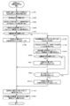
- FIG. 6 is a diagram showing a flow of product introduction processing performed in the unmanned store system according to the first embodiment.
- FIG. 7 is a diagram showing a flow of input control processing according to the first embodiment.
- FIG. 6 is a diagram showing a flow of commodity sales processing performed in the unmanned store system according to the first embodiment.
- FIG. 6 is a diagram showing a flow of recommended product determination processing according to the first embodiment.
- FIG. 6 is a diagram showing a flow of settlement processing according to the first embodiment. It is a figure which shows typically the screen of the user terminal before transmitting a payment request
- FIG. 7 is a diagram showing the flow of the transportation destination determination process according to the first embodiment.
- FIG. 6 is a diagram showing a flow of transport control processing according to the first embodiment. It is a figure which shows the flow of the conveyance control processing performed following FIG. 17A.
- FIG. 8 is a diagram for describing an operation example of the automatic warehouse in the transport control process according to the first embodiment. It is a figure which shows the mode of the automatic warehouse after FIG. 18A. It is a figure which shows the mode of the automatic warehouse after FIG. 18B. It is a figure which shows the mode of the automatic warehouse after FIG. 18C.
- FIG. 18A shows the mode of the automatic warehouse after FIG. 18A.
- FIG. 18B shows the mode of the automatic warehouse after FIG. 18B.
- FIG. 18C shows the mode of the automatic warehouse after FIG.
- FIG. 8 is a diagram for describing an operation example of the automatic warehouse in the transport control process according to the first embodiment. It is a figure which shows the mode of the automatic warehouse after FIG. 19A. It is a figure which shows the mode of the automatic warehouse after FIG. 19B.
- FIG. 8 is a diagram for describing an operation example of the automatic warehouse in the transport control process according to the first embodiment. It is a figure which shows the mode of the automatic warehouse after FIG. 20A. It is a figure which shows the mode of the automatic warehouse after FIG. 20B.
- FIG. 14 is a diagram showing a flow of settlement processing according to the second embodiment.
- FIG. 18 is a diagram showing a flow of recommended product determination processing according to the third embodiment.
- the direction facing the user is referred to as "front”, and the direction opposite to the front is referred to as “back”.
- the height direction of the store is referred to as “upper”, and the direction opposite to the upper direction is referred to as “lower”.
- a direction perpendicular to each of the front and rear direction and the vertical direction is referred to as a “width direction”.
- FIG. 1 is a diagram showing an entire configuration of an unmanned shop system 1 according to a first embodiment of the present invention.
- FIG. 2 is a view showing an appearance configuration of the unmanned store 10 according to the first embodiment.
- the unmanned store system 1 is a system for operating the unmanned store 10.
- the unmanned store 10 is a store where users who visit the store can purchase various products such as food, sundries, daily necessities, home appliances and the like.
- the unmanned store 10 is a store where users who visit the store can purchase these various products without manual intervention.
- the unmanned store 10 may be a retail store, such as a convenience store and a supermarket, in which the process of purchasing a product by a user is unmanned.
- the unmanned store system 1 includes an unmanned store 10, a management server 50, a settlement server 60, an operator terminal 70, and a user terminal 80, as shown in FIG.
- the unmanned store 10, the management server 50, the settlement server 60, the operator terminal 70, and the user terminal 80 are connected to a communication line that constructs a computer network.
- the unmanned store 10 is installed adjacent to the sales area 11 and the sales area 11 divided by the sales apparatus 20 that sells the product to the visiting user, and is sold by the sales apparatus 20.
- an automated warehouse 30 for storing the goods to be stored.
- the sales area 11 and the automated warehouse 30 are separated by a bulkhead 12.
- the user who has visited the unmanned store 10 passes through the gate 13 and enters the sales area 11, and after purchasing a product, the user passes the gate 13 and exits the sale area 11.
- a user who has visited the unmanned store 10 can not enter the automated warehouse 30.
- FIG. 3 is a front view of the sales apparatus 20 according to the first embodiment.
- FIG. 4 is a diagram showing a functional configuration of the sales device 20 according to the first embodiment.
- the sales apparatus 20 is an apparatus for selling goods unmanned, and is installed on the wall of the bulkhead 12 on the sales area 11 side.
- a plurality of vending devices 20 are disposed along the wall surface of the partition wall 12. Each of the plurality of vending devices 20 can sell goods independently.
- Each of the plurality of vending devices 20 is, as shown in FIGS. 3 and 4, a display unit 21, an outlet 22, a door 23, an outlet sensor 24, a camera 26, a speaker 27, and a communication unit. 28 and a control unit 29.
- the display unit 21 is a display that displays information on a product sold by the sales apparatus 20.
- the display unit 21 is provided at the front center of the sales apparatus 20.
- the display unit 21 associates and displays the product information of the product to be sold and the code image G including the payment request for requesting the payment of the product to be performed.
- the product information displayed on the display unit 21 is information such as an image, a name, a price, and a product description of a product to be sold.
- the settlement request is information for requesting the settlement server 60 that the settlement of the product is performed by accessing the settlement server 60 when the user purchases the product and performing processing for payment of the product price.
- the code image G is a two-dimensional code image obtained by encoding the payment request, the product information, the sales device information, and the like.
- the sales device information is identification information of the sales device 20 on which the code image G is displayed, and may be information for identifying the outlet 22 provided in the sales device 20.
- the sales device information can be the same information in a plurality of code images G displayed on the display unit 21 of one sales device 20.
- the display unit 21 is configured of a touch screen that receives a touch operation of the user.
- the display unit 21 can change the display mode of the product information of the product selected by the user by the touch operation and the code image G.
- the display unit 21 can enlarge the display area of the product selected by the user and display the product information in detail.
- the display unit 21 can adjust the display area of the code image G so that the user can easily pick up an image, and can emphasize and display the code image G so that the code image G stands out.
- the outlet 22 is an opening for the user to retrieve the product from the sales apparatus 20.
- the outlet 22 is provided at the lower front of the vending apparatus 20.
- the outlet 22 is provided with a door 23 that covers the opening from the sales area 11 side.
- the door 23 is automatically opened when the user can take out the product from the outlet 22, and is automatically closed after the user takes out the product from the outlet 22.
- the opening and closing operation of the door 23 is performed based on whether or not the outlet sensor 24 provided in the receiving portion 25 inside the outlet 22 has detected a product.
- the outlet sensor 24 may be configured of a reflective or transmissive photosensor or a weight sensor or the like.
- the receiving portion 25 is formed to be inclined obliquely downward as it goes from the rear to the front, and the product placed on the receiving portion 25 slides , Formed so as to stay in the vicinity of the door 23.
- the camera 26 is provided on the front top of the sales apparatus 20 and captures images of the sales area 11 and the user.
- the camera 26 may be a camera for monitoring the state of the sales area 11 for the purpose of crime prevention or the like.
- the camera 26 may be a camera for capturing an image of the user who has approached the sales apparatus 20 for the purpose of displaying on the display unit 21 the product according to the attribute of the user.
- the camera 26 can acquire an image necessary to analyze the user's attributes by face recognition or gait recognition or the like.
- the speaker 27 is provided at the upper front of the sales device 20 and emits a voice to the sales area 11.
- the speaker 27 can emit a sound indicating that the product can be taken out from the outlet 22, and can notify the user.
- the communication unit 28 is a communication module that performs wired or wireless communication with the automated warehouse 30 and the management server 50.
- the control unit 29 is a control unit that includes a processor and a storage device and centrally controls the operation of the sales apparatus 20.
- the control unit 29 is connected to the outlet sensor 24, the door 23 and the speaker 27. Then, the control unit 29 controls the opening / closing operation of the door 23 based on the detection result of the outlet sensor 24 and controls the operation of the speaker 27 that emits a sound indicating that the product can be taken out. Further, the control unit 29 is connected to the camera 26 and acquires an image captured by the camera 26. Further, the control unit 29 is connected to the communication unit 28 and the display unit 21.
- control unit 29 acquires the product information and the like transmitted by the management server 50 from the communication unit 28, creates the code image G, and causes the display unit 21 to display the code image G in association with the product information. Furthermore, the control unit 29 transmits, from the communication unit 28 to the automatic warehouse 30, a removal completion notification indicating that the user has removed the product from the removal port 22.
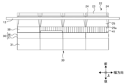
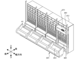
- FIG. 5 is a perspective view schematically showing the internal configuration of the automatic warehouse 30 and the outlet 22 according to the first embodiment.
- FIG. 6A is a view schematically showing the shelf 31 provided in the automatic warehouse 30 shown in FIG. 5 as viewed from the front.
- FIG. 6B is a view schematically showing the automatic warehouse 30 and the outlet 22 shown in FIG. 5 as viewed from above.
- FIG. 6C is a view schematically showing the automatic warehouse 30 and the outlet 22 shown in FIG. 5 as viewed in the width direction.
- FIG. 6D is a view schematically showing the belt conveyor 32 provided in the automatic warehouse 30 shown in FIG. 5 as viewed from the width direction.
- FIG. 7 is a diagram showing a functional configuration of the automatic warehouse 30 according to the first embodiment.
- the automatic warehouse 30 is an automatic warehouse that stores goods sold by the sales device 20 and automatically transports the stored goods to the sales device 20.
- the automatic warehouse 30 is a warehouse shared by a plurality of sales devices 20, and transports goods to the respective outlets 22 of the plurality of sales devices 20.
- the automatic warehouse 30 includes a shelf 31, a belt conveyor 32, an inlet sensor 34, an elevator 35, a pusher 38, a transfer mechanism 41, and a temperature control device 43.
- the storage commodity monitoring unit 44, the transport apparatus monitoring unit 45, the communication unit 46, and the control unit 47 are provided.
- the shelf 31 is a shelf for storing goods sold by the sales device 20.
- a plurality of shelves 31 are arranged along the width direction of the shelf 31 as shown in FIG. 6A.
- the width direction of the shelf 31 is substantially parallel to the width direction of the vending apparatus 20.
- the plurality of shelves 31 can store the products separately for each shelf 31 according to the storage environment of the stored products.
- the plurality of shelves 31 can store the products separately for each section in the shelf 31 according to the storage environment of the stored products.
- the plurality of shelves 31 may store frequently sold goods in a row near the pusher 38.
- the shelf 31 is provided with an insertion port 31a for inserting goods to be stored into the shelf 31 on the rear side of the shelf 31, that is, on the opposite side to the elevator 35.
- the shelf 31 is configured such that the back plate portion 31c on the rear side of the shelf 31 can be opened and closed freely, and goods are introduced from the insertion port 31a by opening the back plate portion 31c.
- the shelf 31 is provided with a discharge port 31 b for discharging the stored goods from the shelf 31 on the front side of the shelf 31, that is, on the elevator 35 side.
- the shelf 31 is configured such that the shelf board portion 31d in which the products are stored is constituted by the belt conveyor 32, and the belt conveyor 32 is provided in multiple stages in the vertical direction and arranged in many in the width direction. That is, the belt conveyor 32 stores the goods by placing the goods on the belt 33.
- the belt conveyor 32 is disposed such that the belt 33 moves in the front-rear direction.
- the belt conveyor 32 has its front end constitutes the lower part of the edge of the discharge port 31b, and its rear end constitutes the lower part of the edge of the inlet 31a. That is, the inlet 31a and the outlet 31b are provided in each of the plurality of belt conveyors 32 arranged in the vertical direction and the width direction.
- the belt conveyor 32 can convey the goods placed on the belt 33 toward the discharge port 31 b and discharge the product from the shelf 31 by moving the belt 33 toward the discharge port 31 b.
- the inlet sensor 34 is provided in the vicinity of the inlet 31a of the belt conveyor 32, as shown in FIG. 6D.
- the insertion port sensor 34 is a sensor that detects whether or not the product is positioned at the insertion port 31 a.
- the inlet sensor 34 may be configured by a reflective or transmissive photosensor or the like.
- An outlet sensor may be provided in the vicinity of the outlet 31b as in the case of the inlet sensor 34, and it may be detected whether or not the product is positioned at the outlet 31b.
- the belt 33 is provided with a plurality of support portions 33 a for supporting the goods placed on the belt 33.
- Each of the plurality of support portions 33 a is provided so as to project upward from the surface on which the product of the belt 33 is placed.
- the plurality of support portions 33a are disposed at intervals according to a predetermined movement amount of a belt 33 described later.
- the distance between the two support portions 33a adjacent to each other in the front-rear direction is designed to correspond to the size in the front-rear direction of the product placed on the belt 33. That is, the sizes of the plurality of products placed on the belt 33 in the front-rear direction are substantially the same in the belt 33.
- the elevator 35 is provided in front of each of the plurality of shelves 31, as shown in FIG. 5, and moves up and down between the plurality of belt conveyors 32 provided in multiple stages.
- Each of the plurality of elevators 35 is associated with each of the plurality of shelves 31 in a one-to-one relationship, and is associated with each of the plurality of outlets 22 in a one-to-one relationship.
- the elevator 35 is provided to move along the columns 36 between the pair of columns 36 and the pair of columns 36 arranged to extend in the vertical direction at predetermined intervals along the width direction of the shelf 31.
- Buckets 37 that can load products.
- the bucket 37 has a frame shape in which a through hole extending in the front-rear direction is formed in a rectangular solid.
- the bucket 37 may have a smooth plate shape or a plate shape subjected to concavo-convex processing by punching or the like.
- the bucket 37 may be provided with a stopper for preventing the falling of the mounted product.
- the elevator 35 moves the bucket 37 to the height of the stage where the storage position of the goods discharged from the shelf 31 is located, and receives the goods transported and discharged by the belt conveyor 32 at this storage position by the bucket 37. Thus, the elevator 35 can load the goods transported by the belt conveyor 32.
- the pusher 38 is an unloading mechanism that unloads the goods mounted on the elevator 35 out of the elevator 35.
- the pushers 38 are provided at predetermined stages of each of the plurality of shelves 31 as shown in FIGS. 5 and 6A.
- Each of the plurality of pushers 38 is associated with each of the plurality of elevators 35 in a one-to-one relationship, and is associated with each of the plurality of shelves 31 in a one-to-one relationship.
- the pusher 38 is, as shown in FIG. 6C, a cylinder 39 which is provided in a predetermined step of the shelf 31 and which is expanded and contracted in the front-rear direction, and an abutting part 40 which is provided at the front end of the cylinder 39 and which abuts on the product. May be included.
- the cylinder 39 and the abutment portion 40 have a shape that penetrates the inside of the bucket 37 of the elevator 35 in the front-rear direction.
- the shape of the cylinder 39 and the contact portion 40 may be any shape that can push the product mounted on the bucket 37 and move it forward.
- the pusher 38 moves in such a manner that the contact portion 40 projects forward from the shelf 31 in response to the expansion and contraction of the cylinder 39 and moves rearward and is stored at a predetermined level of the shelf 31.
- the pusher 38 pushes the goods loaded on the bucket 37 forward by projecting the abutment portion 40 forward. Thereby, the pusher 38 can carry out the goods mounted on the elevator 35 out of the elevator 35.
- each of the plurality of pushers 38 is associated with each outlet 22 of the plurality of vending apparatuses 20 in a one-to-one relationship. As shown in FIG. 5 and FIG. 6B, each of the plurality of pushers 38 is positioned such that each of the plurality of outlets 22 is located ahead of each direction for pushing out the articles mounted on each of the plurality of elevators 35. Provided. In other words, each of the plurality of pushers 38 pushes the articles mounted on each of the plurality of elevators 35 toward each of the plurality of outlets 22. Furthermore, each of the plurality of pushers 38 is configured to project until the respective abutments 40 reach the rear end 25 a of the respective receiving portions 25 of the plurality of outlets 22.
- each of the plurality of pushers 38 not only carries out the goods mounted on each of the plurality of elevators 35 out of each of the plurality of elevators 35 and places it on the transfer mechanism 41, but also the plurality of outlets 22. Can reach each of Furthermore, each of the plurality of pushers 38 can close the receiving portion 25 of each of the plurality of outlets 22 from the rear even when the door 23 of each of the plurality of outlets 22 is open.
- the transfer mechanism 41 is a mechanism which transfers the goods carried out of the elevator 35 along the width direction.
- the transfer mechanism 41 is provided between the plurality of elevators 35 provided on each of the plurality of shelves 31 and the plurality of outlets 22.
- the transfer mechanism 41 may be configured by, for example, a roller conveyor, a belt conveyor, a carriage, or the like.
- the transfer mechanism 41 may be provided such that the height of the surface on which the product is placed is substantially the same height as the predetermined level of the shelf 31 provided with the pusher 38.
- the transfer mechanism 41 may be provided such that the direction in which the product is transported is substantially orthogonal to the direction in which the pusher 38 pushes out the product.
- the transfer mechanism 41 allows one pusher 38 and one item to be smoothly transported on the transfer mechanism 41 when one pusher 38 causes a product mounted on one elevator 35 to reach one corresponding outlet 22. In order to pass through, the operation is kept stopped. On the other hand, when the transfer mechanism 41 causes the goods with the one pusher 38 mounted on the one elevator 35 to reach the other outlet 22, the goods are placed on the transfer mechanism 41 by the one pusher 38 and then the goods are removed. Start transferring the placed goods to the other outlet 22. The transfer mechanism 41 stops the transfer operation when the placed commodity is transferred to the same position as the other outlets 22 in the front-rear direction. Then, the goods placed on the transfer mechanism 41 can be pushed forward by the other pushers 38 corresponding to the other outlets 22 and reach the other outlets 22.
- the articles stored in the shelf 31 are transported to the outlet 22 of the vending apparatus 20 by the cooperation of the belt conveyor 32, the elevator 35, the pusher 38 and the transfer mechanism 41.
- the belt conveyor 32, the elevator 35, the pusher 38, and the transfer mechanism 41 are collectively referred to as a "carrier device 42".
- the temperature control device 43 is a device that adjusts the temperature of the goods stored on the shelf 31.
- the temperature control device 43 can adjust the temperature of the product separately for each shelf 31 according to the storage environment of the stored product.
- the temperature control device 43 shown in FIG. 6A can control the temperature of goods by dividing each shelf 31 into four storage environments of freezing, refrigeration, normal temperature, and heating.
- the plurality of shelves 31 can be divided for each section in the shelf 31 according to the storage environment of the stored product to adjust the temperature of the product.
- the temperature control device 43 may be configured by a heat pump.
- the stored product monitoring unit 44 monitors the storage status of the product stored on the shelf 31.
- the stored product monitoring unit 44 is configured by various sensors, and creates storage information indicating the storage status of the product stored on the shelf 31.
- the storage information is information indicating storage positions, storage times, stock numbers, and the like of each of the plurality of products stored in the shelf 31.
- the transport device monitoring unit 45 monitors the operating status of the transport device 42.
- the transporting device monitoring unit 45 is configured by various sensors, and creates operation information indicating the operating status of the belt conveyor 32 which is the transporting device 42, the elevator 35, the pusher 38, and the transfer mechanism 41.
- the operation information is information indicating an operation state, an operation time, an operation frequency, and the like of the transport device 42.
- the communication unit 46 is a communication module that performs wired or wireless communication with the sales apparatus 20, the management server 50, and the operator terminal 70.
- the control unit 47 is a control unit that includes a processor and a storage device and centrally controls the operation of the automatic warehouse 30.
- the control unit 47 is connected to the transport device 42 and the communication unit 46, acquires from the communication unit 46 the transport instruction transmitted by the management server 50, and is based on the acquired transport instruction. Control the operation of the transport device 42.
- the transport command is a command for transporting the goods stored in the shelf 31 to the outlet 22 of the sales apparatus 20.
- the control unit 47 transmits, from the communication unit 46 to the management server 50, a transport completion notification indicating that the product has been transported to the outlet 22 of the sales apparatus 20.
- control unit 47 is connected to the inlet sensor 34, acquires from the communication unit 46 the input command transmitted by the operator terminal 70, and based on the acquired input command and the detection result of the inlet sensor 34, The operation of the conveyor 32 is controlled.
- the input instruction is an instruction for causing the operator to insert a product into the shelf 31.
- control unit 47 is connected to the stored product monitoring unit 44 and the transport device monitoring unit 45, acquires storage information and operation information from the stored product monitoring unit 44 and the transport device monitoring unit 45, and manages them from the communication unit 46. Send to server 50. Further, the control unit 47 is connected to the temperature control device 43, and controls the operation of the temperature control device 43 based on the storage information acquired from the storage product monitoring unit 44.
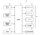
- FIG. 8 is a diagram showing a functional configuration of the management server 50 according to the first embodiment.
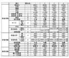
- FIG. 9A is a diagram for explaining product information, storage information, and sales information managed by the management server 50 according to the first embodiment.
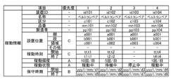
- FIG. 9B is a diagram for describing operation information managed by the management server 50 according to the first embodiment.
- the management server 50 is a server that manages the unmanned store 10. Specifically, the management server 50 manages the goods stored by the automatic warehouse 30, the transport device 42 provided in the automatic warehouse 30, and the sales device 20 installed in the sales area 11.
- the management server 50 may be a server that manages a plurality of unmanned stores 10.
- the management server 50 includes a commodity sales management unit 51, a transport device management unit 52, a communication unit 53, and a control unit 54.
- the commodity sales management unit 51 is a database in which various information for managing the storage status and the sales status of the commodity in the unmanned store 10 is registered and its management system.
- the product sales management unit 51 manages at least product information, storage information, and sales information.
- the product information is registered in the product sales management unit 51 by dividing various information related to the attribute of the product into items.
- the items included in the product information are, for example, product ID which is product identification information, product name, image, classification, part number, manufacturer (producer), manufacturing place (production place), price, storage environment, size, It may be in shape, time of sale, expiration date, etc.
- the storage environment is information defined by the manufacturer (producer) about the optimum temperature environment for storing products, such as freezing, refrigeration, normal temperature, and storage.
- the sales time includes the sales start time and the sales end time of the sales apparatus 20, and if the date is not registered in both the sales start time and the sales end time, the product is not a limited-time product but always sold. Indicates
- the storage information is registered in the product sales management unit 51 by dividing various information related to the storage status of the product into items.
- the storage information is registered in association with product information (product ID).
- the items included in the storage information may be, for example, the storage position of the product, the storage time, the storage environment, the number of stocks, the sales status, and the like.
- the storage position may be defined by the identification information of each shelf 31, the identification information of each row in the shelf 31, and the identification information of each storage area in the row.
- the storage time includes arrival time, which is the date when the product is put into a specific storage position of the shelf 31, and shipping time, which is the date when it is discharged from the specific storage position of the shelf 31.
- the storage environment is information indicating the temperature environment in which the product is actually stored, such as freezing, refrigeration, normal temperature, and storage.
- the sales state is information indicating whether the item is an item for sale.
- the sales information is registered in the product sales management unit 51 by dividing various information on the sales status of the product into items.
- the sales information is registered in association with product information (product ID).
- product ID product information
- the items included in the sales information may be, for example, the sales amount in a predetermined period, the number of sales, the number of customers, the purchase time slot, the user evaluation, and the like.
- the sales information may be POS (Point of Sales) data.
- the transport apparatus management unit 52 is a database in which various information for managing the operation status of the transport apparatus 42 in the automatic warehouse 30 is registered and a management system thereof.
- the transport apparatus management unit 52 manages at least operation information.
- the operation information is registered in the conveyance device management unit 52 by dividing various information related to the operation state of the conveyance device 42 into items.
- the items included in the operation information are, for example, the device ID which is identification information of the transportation device 42, the name of the transportation device 42, classification, part number, manufacturer, installation position, operation time, operation frequency, operation state, maintenance time, etc. May be there.
- the installation position is information indicating the position at which the transport device 42 is installed. If the transport device 42 is the belt conveyor 32, the installation position may be defined by the identification information of each shelf 31, the identification information of each stage in the shelf 31, and the identification information of each storage area in the stage It can correspond to the storage location of information.
- the installation position may be defined by the identification information of each shelf 31. If the transport device 42 is the transfer mechanism 41, the installation position may be identification information indicating a specific space in the automated warehouse 30.
- the operation time is information indicating the time when the operation of the transport device 42 starts and ends in a predetermined period.
- the operation frequency is information indicating the frequency at which the transport device 42 has been operated in a predetermined period.
- the operating state is information indicating whether the transport device 42 is in operation, in standby or in suspension.
- the maintenance time indicates the maintenance start time and end time of the transportation device 42 which is regularly maintained.
- the management server 50 can determine a recommended product which is a product to be recommended to the user who has visited the store, based on the product information, the storage information, the sales information, and the operation information. Then, the management server 50 can promote the sale of the product by displaying the product information of the determined recommended product on the sales device 20 and promoting it to the user who has visited the store.
- the priority is an index indicating which item is to be preferentially evaluated as an evaluation target when the management server 50 determines a recommended product.
- the priority is predetermined by the operator or operator of the unmanned store 10 or the management server 50.
- a process performed by the management server 50 to determine a recommended product is also referred to as a “recommended product determination process”. Details of the recommended product determination process will be described later with reference to FIG.
- the communication unit 53 is a communication module that performs wired or wireless communication with the sales apparatus 20, the automatic warehouse 30, the settlement server 60, and the operator terminal 70.
- the control unit 54 is a control unit that includes a processor and a storage device and centrally controls the operation of the management server 50.
- the control unit 54 is connected to the product sales management unit 51, the transport apparatus management unit 52, and the communication unit 53, and from the product sales management unit 51 and the transport apparatus management unit 52, the product information, sales information, storage information and operation information get. Then, based on the acquired product information, sales information, storage information, and operation information, the control unit 54 determines a product to be input to the automatic warehouse 30 for sale by the sales apparatus 20, and inputs a product input command. Are transmitted from the communication unit 53 to the operator terminal 70.
- control unit 54 creates a sales instruction of the put-in product, and transmits it from the communication unit 53 to the automatic warehouse 30 and the sales apparatus 20.
- the sales instruction is an instruction for starting the sales of the introduced product.
- the management server 50 transmits product information of a product to be sold by the sales apparatus 20 from the communication unit 53 to the sales apparatus 20 and causes the display unit 21 to display the information.
- the management server 50 acquires the settlement completion notification transmitted by the settlement server 60 from the communication unit 53, creates a transportation instruction, and transmits the conveyance instruction from the communication unit 53 to the automatic warehouse 30.
- the settlement completion notification is a notification indicating that the settlement server 60 performs settlement according to the settlement request and that the settlement of the product is completed.
- the settlement server 60 is a server that performs settlement of goods in response to a settlement request.
- the settlement server 60 may be a server owned by a settlement organization independent of the unmanned store 10 and the management entity of the management server 50.
- the settlement server 60 is configured to be communicable with the management server 50 and the user terminal 80, performs settlement of the product for which purchase is designated by the user in response to the settlement request, and transmits a settlement completion notification to the management server 50.
- the user picks up the code image G of the product displayed on the display unit 21 with the user terminal 80, and transmits the settlement request included in the code image G to the settlement server 60 to specify the product to be purchased.
- settlement server 60 settlement of goods is performed by electronic settlement, but the settlement method is not particularly limited, such as a prepaid method, a just pay method, a post pay method, and the like.
- electronic money used in electronic payment may be configured by legal currency, corporate currency (points), virtual currency, or a combination thereof.
- the settlement server 60 can accumulate the settlement history for each user, and can give the user a benefit according to the settlement history.
- the operator terminal 70 is an information terminal of an operator who manages the unmanned store 10.
- the operator terminal 70 is configured to be communicable with the management server 50 and the automatic warehouse 30, and stores product information, storage information, sales information, and the like of goods to be introduced into the automatic warehouse 30 for sale by the sales apparatus 20. It can be displayed.
- the operator terminal 70 may be configured to communicate with the sales device 20, the transport device 42, and the management server 50 to remotely control these.
- the user terminal 80 is an information terminal of a user who has visited the unmanned store 10.
- the user terminal 80 incorporates a camera capable of capturing the code image G displayed on the display unit 21 and an application program for performing payment processing with the payment server 60.
- the settlement process is a process related to the settlement of goods performed between the user terminal 80 and the settlement server 60. The details of the settlement process will be described later with reference to FIG.
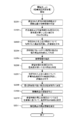
- FIG. 10 is a diagram showing the flow of the commodity introduction process performed by the unmanned shop system 1 according to the first embodiment.
- the unmanned store system 1 goods sold by the sales apparatus 20 are put into the rack 31 of the automatic warehouse 30 by the operator.
- the process performed by the unmanned store system 1 in order to put the goods stored in the automatic warehouse 30 into the rack 31 is also referred to as the “product introduction process”.
- the goods to be put into the shelf 31 are also referred to as "input goods”.
- the unmanned store system 1 there is a case in which the goods introduced before the goods introduction processing are already stored in the shelf 31 and the goods information is displayed on the sales apparatus 20.
- a product which has been loaded before the product loading process and has already been stored in the shelf 31 is also referred to as an “existing product”.
- the product introduction process shown in FIG. 10 is described focusing on the product introduction process when one product is introduced, and the product introduction process and the product sale process for other products are described. It does not prevent being done in parallel.
- the management server 50 specifies the product information of the input product, the storage position, and the target number of inputs. For example, the management server 50 specifies the storage position of the input product on the shelf 31 based on the product size, the storage environment, and the like included in the product information of the input product.
- step 1002 the management server 50 creates an input command including the specified product information, the storage position, and the target input number, and transmits the input command to the operator terminal 70.
- step 1003 when the operator terminal 70 receives the input command of the input product transmitted by the management server 50, the operator terminal 70 displays the product information, the storage position, and the target number of input of the input product included in the received input command. The operator can load the input product into the shelf 31 based on the displayed product information, the storage position, and the target number of inputs.
- the operator terminal 70 transmits an input command of the input product to the automatic warehouse 30.
- the operator may switch the automatic warehouse 30 to the commodity insertion mode by the operation at the operator terminal 70 and transmit the insertion instruction to the automatic warehouse 30.
- the operator may switch the automated warehouse 30 to the commodity loading mode by operating a predetermined operation panel or the like provided in advance in the automated warehouse 30, and transmit the loading instruction to the automated warehouse 30. The operator can manually load the input product into the shelf 31 after transmitting the input command.
- step 1005 when the automatic warehouse 30 receives the insertion command of the put-in product transmitted from the operator terminal 70, the automatic warehouse 30 performs a put-in control process.
- the input control process is a process performed by the automatic warehouse 30 to appropriately input the input goods to the shelf 31. Details of the input control process will be described later with reference to FIG.
- step 1006 the automatic warehouse 30 transmits storage information and the like of the input product to the operator terminal 70 after the input control process.
- the operator terminal 70 can display the received storage information and the like when receiving the storage information and the like transmitted by the automatic warehouse 30.
- the operator can confirm the actual input result of the input product based on the displayed storage information.
- the automated warehouse 30 proceeds to step 1014.
- step 1007 the operator terminal 70 transmits, to the management server 50, an input completion notification including storage information and the like of the input product.
- the input completion notification is a notification indicating that the input product has been properly input to the shelf 31 and the input has been completed.
- the management server 50 receives the insertion completion notification transmitted by the operator terminal 70, the management server 50 updates the registered storage information based on the storage information included in the received insertion completion notification. Thereafter, the operator terminal 70 ends the present process.
- step 1008 the management server 50 confirms the product information of the input product, and determines whether the input product is a newly released product different from the existing product. When the input product is a new release product, the management server 50 proceeds to step 1009. On the other hand, when the input product is not a newly released product, the management server 50 determines that the input product is the same product as the existing product and is a product that replenishes the stock of the existing product, and ends this processing.
- step 1009 the management server 50 confirms the product information of the input product, and specifies the sales start time of the input product.
- step 1010 the management server 50 determines whether the sales start time of the input product has come. When the sales start time of the input product has not come, the management server 50 stands by for the product introduction process until the sales start time of the input product comes. On the other hand, when the sales start time of the input product has come, the management server 50 proceeds to step 1011.
- step 1011 the management server 50 confirms storage information of the input product, and determines whether the input product is stored at the storage position of the existing product. In other words, the management server 50 determines whether there is an existing product at the storage position of the input product. If there is no existing product at the storage position of the input product, the management server 50 proceeds to step 1013. On the other hand, when there is an existing product at the storage position of the input product, the management server 50 proceeds to step 1012.
- the management server 50 determines whether or not the stock quantity of the existing product at the storage position of the input product has become zero.
- the management server 50 determines whether or not the notification of selling out of the existing product at the storage position of the input product has been received from the automatic warehouse 30, whereby the stock quantity of the existing product at the storage position of the input product becomes zero. Determine if it was.
- the management server 50 waits for the product loading process until the number of existing products in the storage position of the input product becomes zero. On the other hand, when the stock quantity of the existing product at the storage position of the input product becomes zero, the management server 50 proceeds to step 1013.
- step S1013 when the number of existing products at the storage position of the input product becomes zero, the management server 50 creates a sales command including the product information and the like of the input product, and transmits it to the automatic warehouse 30 and the sales apparatus 20. . Thereafter, the management server 50 ends the present process.
- step 1014 the automated warehouse 30 confirms the product information of the input product, and determines whether the input product is a newly released product different from the existing product. If the input product is a newly released product, the automatic warehouse 30 proceeds to step 1015. On the other hand, when the input product is not a newly released product, the automatic warehouse 30 determines that the input product is the same product as the existing product and is a product that replenishes the stock of the existing product, and ends this processing.
- step 1015 the automatic warehouse 30 is set to hold the sales of the input product until the sales command of the input product transmitted by the management server 50 is received.
- step 1016 the automated warehouse 30 checks storage information of the input product, and determines whether the input product is stored at the storage position of the existing product. In other words, the automatic warehouse 30 determines whether there is an existing product at the storage position of the input product. If there is no existing product at the storage position of the input product, the automatic warehouse 30 proceeds to step 1019. On the other hand, when there is an existing product at the storage position of the input product, the automatic warehouse 30 proceeds to step 1017.
- step 1017 the automated warehouse 30 determines whether the number of existing items in stock at the storage position of the input item has become zero.
- the automated warehouse 30 waits for the product loading process until the number of existing products in the storage position of the input product becomes zero. On the other hand, when the stock quantity of the existing product at the storage position of the input product becomes zero, the automatic warehouse 30 proceeds to step 1018.
- step 1018 the automated warehouse 30 transmits storage information indicating that the number of stock of the input product is zero to the management server 50, including in the sales-out notice of the existing product.
- step 1019 the automated warehouse 30 determines whether or not the sales instruction of the inserted commodity transmitted by the management server 50 has been received.
- the automatic warehouse 30 waits for the commodity insertion process until the sales instruction of the inserted product transmitted by the management server 50 is received.
- the processing moves to step 1020.
- step 1020 when the automatic warehouse 30 receives the sales instruction of the put-in product transmitted by the management server 50, the automatic warehouse 30 is set to start the sales of the put-in product which has been suspended. Thereafter, the automatic warehouse 30 ends the process.
- step 1021 when the sales device 20 receives the sales instruction of the inserted product transmitted by the management server 50, the sales device 20 receives the product information of the inserted product, the settlement request of the input product, the sales device information, etc. Encode to create a code image G. Then, the sales apparatus 20 displays the generated code image G in association with the product information of the input product. Thereafter, the vending device 20 ends the present process.
- the input product is a product different from the existing product already stored on the belt conveyor 32
- the selling device 20 loses the existing product and after the sales start time of the input product has come. , Product information etc. of the input product can be displayed.
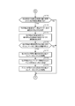
- FIG. 11 is a diagram showing the flow of input control processing according to the first embodiment.
- step 1101 when the automated warehouse 30 receives the input command of the input commodity transmitted from the operator terminal 70, the automatic warehouse 30 specifies the storage position where the input commodity is stored and the product size of the input commodity based on the received input instruction. Do.
- step 1102 the automated warehouse 30 determines whether the existing product is stored in the belt conveyor 32 at the storage position of the input product.
- the automatic warehouse 30 proceeds to step 1106 if the existing product is not stored.
- the automatic warehouse 30 shifts to step 1103.
- the size of the existing product stored in the belt conveyor 32 at the storage position of the input product is substantially the same as the size of the input product in the front-rear direction.
- step 1103 the automated warehouse 30 moves the belt 33 toward the inlet 31 a so that the existing product is positioned at the inlet 31 a.
- step 1104 the automatic warehouse 30 determines whether the existing product is positioned at the insertion port 31 a based on the detection result of the insertion port sensor 34. If the existing product is not located at the input port 31a, the automatic warehouse 30 proceeds to step 1103. On the other hand, when the existing product is located at the input port 31a, the automated warehouse 30 proceeds to step 1105.
- the automatic warehouse 30 moves the belt 33 toward the discharge port 31b by a predetermined movement amount according to the size of the input goods.
- the predetermined movement amount corresponds to an interval between two support portions 33a adjacent to each other in the front-rear direction on the belt 33 at the storage position of the input product. This interval is an interval according to the size of the input product in the front-rear direction.
- step 1106 the automatic warehouse 30 notifies the operator that the input of the product can be started. Specifically, the automatic warehouse 30 gives a notification by displaying on a predetermined operation panel or the like or transmitting to the operator terminal 70 that introduction of goods can be started. The operator can manually load the input product into the input port 31a.
- step 1107 the automatic warehouse 30 determines, based on the detection result of the insertion port sensor 34, whether or not the input commodity is positioned at the insertion port 31a.
- the automatic warehouse 30 stands by until it is detected that the input product is located at the input port 31a.
- the automated warehouse 30 proceeds to step 1108.
- step 1108 the automatic warehouse 30 moves the belt 33 toward the discharge port 31b by a predetermined movement amount according to the size of the input goods.
- the predetermined amount of movement is the same as the amount of movement at step 1105 described above.
- step 1109 the automatic warehouse 30 increments the number of times of movement of the belt 33.
- the number of times of movement of the belt 33 is the number of times of movement of the belt 33 toward the discharge port 31b by a predetermined movement amount.
- the automated warehouse 30 determines whether or not the input of goods has been completed.
- the operator may transmit from the operator terminal 70 to the automatic warehouse 30 that the input of the product has been completed when the input of the product has been completed.
- the operator may notify the automatic warehouse 30 by operating a predetermined operation panel or the like that the input of goods has been completed.
- the automatic warehouse 30 may determine whether or not the input of the product has ended based on the timing of the timer. Specifically, the automatic warehouse 30 determines that the introduction of the product is not finished until the timer counts the elapse of the predetermined time, and determines that the insertion of the commodity ends when the timer counts the elapse of the predetermined time. You may The automatic warehouse 30 proceeds to step 1107 when the input of the product has not been completed. On the other hand, when the input of goods has been completed, the automated warehouse 30 proceeds to step 1111.
- the automatic warehouse 30 acquires the number of inputs, which is the number of input products actually input, based on the number of movements of the belt 33.
- the automatic warehouse 30 moves the belt 33 to the discharge port 31b by a predetermined movement amount each time the input commodity is input.
- the predetermined movement amount is a movement amount according to the size of the input product in the front-rear direction.
- the automated warehouse 30 increments the number of times of movement of the belt 33 each time an input commodity is introduced. For this reason, the number of times of movement of the belt 33 after the end of the input of the product corresponds to the number of input of the input product. For example, when the number of movements of the belt 33 is two, the automatic warehouse 30 can determine that the number of inputs is two.
- the automatic warehouse 30 calculates the target moving amount of the belt 33 up to the discharge port 31 b based on the stock quantity of the existing product at the storage position of the input product and the acquired number of inputs.
- the upper limit value of the articles that can be stored on one of the belt conveyors 32 constituting the shelf portion 31d of the shelf 31 is determined in advance, and corresponds to the distance between the inlet 31a and the outlet 31b. Further, the stock quantity of the existing product at the storage position of the input product is grasped in advance by the storage information.
- the automated warehouse 30 moves the belt 33 toward the discharge port 31b by the calculated target movement amount.
- the product located at the front can be positioned at the discharge port 31b.
- the product positioned at the discharge port 31 b is a product discharged from the shelf 31 by transport to the sales apparatus 20 or the like, and is a product on standby for discharge from the shelf 31.
- the automatic warehouse 30 can quickly carry the product to the sales apparatus 20 by locating the foremost commodity among the commodities stored on the belt conveyor 32 at the discharge port 31 b.
- step 1114 the automated warehouse 30 creates storage information of the input product. Thereafter, the automatic warehouse 30 ends the process.
- FIG. 12 is a diagram showing the flow of the commodity sales process performed by the unmanned store system 1 according to the first embodiment.
- the automated warehouse 30 monitors the goods and the transport device 42 stored on the shelf 31, creates storage information and operation information, and transmits the storage information and the operation information to the management server 50.
- the management server 50 registers the storage information and the operation information transmitted by the automatic warehouse 30, and manages the storage state of the product and the operation state of the transport device 42 based on the information.
- the unmanned store system 1 the item information and the code image G are displayed on the display unit 21 of the sales apparatus 20 to sell the item to the user who has visited the unmanned store 10.
- the process performed by the unmanned store system 1 to sell goods to the user is also referred to as “merchandise sale process”.
- the user captures the code image G of the product displayed on the display unit 21 of the sales apparatus 20 at the user terminal 80, and transmits the payment request included in the code image G to the payment server 60 to purchase the product to be purchased. It can be specified.
- a product whose purchase has been designated by the user is also referred to as “designated product”.
- the product sales process shown in FIG. 12 is described focusing on the product sales process when one product is sold, and the product sales process and the product introduction process for other products are described. It does not prevent being done in parallel.
- the management server 50 performs recommended product determination processing. Details of the recommended product determination process will be described later with reference to FIG.
- step 1202 the management server 50 transmits product information and storage information of a product sold by the sales apparatus 20 to the sales apparatus 20.
- the products sold by the sales apparatus 20 may include the recommended products determined in step 1201. Thereafter, the management server 50 proceeds to step 1208.
- step 1203 when the sales device 20 receives the product information and the storage information transmitted by the management server 50, the sales device 20 encodes the received product information, a settlement request for the product indicated by the product information, the sales device information, etc. , Code image G is created. Then, the sales apparatus 20 displays the generated code image G in association with the product information. The user can check the product information displayed on the sales apparatus 20 and select a product by touch operation.
- step 1204 the vending apparatus 20 determines whether a touch operation has been received by the display unit 21. If the selling device 20 does not receive the touch operation, the selling device 20 proceeds to step 1216. On the other hand, when the sales device 20 receives a touch operation, the processing proceeds to step 1205.
- step 1205 the sales device 20 changes the display mode of the product information of the selected product and the code image G, and proceeds to step 1216.
- the sales apparatus 20 enlarges the display area of the selected product and displays the product information in detail.
- the sales apparatus 20 adjusts the display area of the code image G so that the user can easily pick up an image, and emphasizes and displays the code image G so that the code image G stands out.
- the sales apparatus 20 captures an image of the user with the camera 26 and acquires an image of the acquired user and an image of the selected product. And can be displayed on the display unit 21.
- the sales apparatus 20 can display related information such as a product, an event or a rendering image related to the selected product on the display unit 21 together with the product information of the selected product.
- the sales apparatus 20 can display on the display unit 21 the advertisement image, the effect image, the product information of the recommended product, and the like regardless of whether the product is selected by the user.
- the sales apparatus 20 has an AR (Augmented Reality) function such as virtual fitting and virtual makeup, and a signage function, and can promote the sale of goods.
- AR Augmented Reality
- step 1206 the user terminal 80 captures the code image G displayed on the sales apparatus 20 by the operation of the user.
- step 1207 the user terminal 80 performs payment processing with the payment server 60 based on the captured code image G.
- a settlement completion notice is transmitted from the settlement server 60 to the management server 50.
- the details of the settlement process will be described later with reference to FIG.
- the user terminal 80 ends the present process. The user stands by until the designated commodity is taken out from the outlet 22 of the sales apparatus 20.
- the management server 50 determines whether the settlement completion notification sent by the settlement server 60 has been received. When the management server 50 has not received the settlement completion notification, the management server 50 stands by until the settlement completion notification is received. On the other hand, when the management server 50 receives the settlement completion notification, the management server 50 proceeds to step 1209.
- step 1209 when receiving the settlement completion notification, the management server 50 updates the sales information of the designated product.
- the management server 50 can grasp that the price of the designated product has been paid by checking the product information of the designated product included in the payment completion notification. Based on that, the management server 50 updates the sales information of the specified product.
- step 1210 when the management server 50 receives the settlement completion notification, the management server 50 performs transport destination determination processing of determining the transport destination of the designated product.
- the transport destination is the outlet 22 of the sales apparatus 20 to which goods stored in the automated warehouse 30 are transported.
- the transport destination determination process is a process of determining which of the plurality of sales devices 20 the removal port 22 is provided to transport the goods.
- the management server 50 performs transport destination determination processing, and creates transport destination information indicating the outlet 22 of the transport destination of the designated product. Details of the transportation destination determination process will be described later with reference to FIG.
- step 1211 the management server 50 transmits, to the automatic warehouse 30, the transportation instruction including the product information of the specified product, the storage position, the transportation destination information, and the like after the transportation destination determination processing. Thereafter, the management server 50 proceeds to step 1214.
- step 1212 when the automated warehouse 30 receives the transportation command of the designated product transmitted by the management server 50, the automated warehouse 30 performs transportation control processing.
- the transport control process is a process performed by the automatic warehouse 30 to transport the designated commodity stored in the shelf 31 to the outlet 22 of the sales apparatus 20. Details of the transport control process will be described later with reference to FIGS. 17A and 17B.
- step 1213 the automatic warehouse 30 transmits, to the management server 50, a conveyance completion notification including storage information and the like of the designated commodity after the conveyance control processing.
- the transport completion notification is a notification indicating that the designated item has been properly transported to the outlet 22 and the transport has been completed. Thereafter, the automated warehouse 30 proceeds to step 1222.
- step 1214 the management server 50 determines whether the transport completion notification sent by the automated warehouse 30 has been received. If the management server 50 has not received the transportation completion notification, the management server 50 waits until receiving the transportation completion notification. On the other hand, when the management server 50 receives the transportation completion notification, the management server 50 proceeds to step 1215.
- step 1215 when receiving the transport completion notice, the management server 50 updates the registered storage information based on the storage information included in the received transport completion notice. Thereafter, the management server 50 ends the present process.
- step 1216 based on the detection result of the outlet sensor 24, the sales apparatus 20 determines whether the designated commodity transported by the automatic warehouse 30 has reached the outlet 22. If the designated item has not reached the outlet 22, the vending apparatus 20 proceeds to step 1204. On the other hand, when the designated item has reached the outlet 22, the selling device 20 proceeds to step 1217.
- the vending apparatus 20 opens the door 23 of the outlet 22 at which the designated commodity has arrived.
- the vending apparatus 20 notifies that the designated commodity can be taken out from the outlet 22.
- the sales apparatus 20 emits a sound indicating that the product can be removed from the outlet 22 from the speaker 27 or displays an image indicating that the product can be removed from the outlet 22 on the display unit 21. Can notify the user. The user can retrieve the designated item from the outlet 22.
- step 1219 the vending apparatus 20 determines whether the designated product has been taken out from the outlet 22 based on the detection result of the outlet sensor 24. If the designated item has not been taken out of the outlet 22, the vending apparatus 20 proceeds to step 1218. On the other hand, when the designated commodity is taken out from the outlet 22, the selling device 20 proceeds to step 1220.
- step 1220 the vending apparatus 20 closes the door 23 of the outlet 22 from which the designated item has been taken out.
- step 1221 the sales apparatus 20 creates a removal completion notification indicating that the specified product has been removed from the removal port 22, and transmits the removal completion notification to the automatic warehouse 30. Thereafter, the vending device 20 ends the present process.
- step 1222 the automated warehouse 30 determines whether the removal completion notification sent by the sales device 20 has been received. If the automatic warehouse 30 has not received the removal completion notification, it waits until receiving the removal completion notification. On the other hand, when the automatic warehouse 30 receives the removal completion notification, it moves on to step 1223.
- the automated warehouse 30 stores the pusher 38 corresponding to the outlet 22 from which the specified commodity is taken out on the shelf 31.
- the pusher 38 keeps the designated commodity pushed out toward the outlet 22 until the door 23 of the outlet 22 closes after the designated commodity reaches the outlet 22.
- the receiving portion 25 of the outlet 22 is closed by the pusher 38 even when the door 23 is open, so that the entry of suspicious objects from the outlet 22 into the interior of the automatic warehouse 30 is suppressed can do.
- the pusher 38 is stored in a predetermined stage of the shelf 31 after the designated commodity is taken out from the outlet 22 and the door 23 is closed. Thereafter, the automatic warehouse 30 ends the process.
- FIG. 13 is a diagram showing a flow of recommended product determination processing according to the first embodiment.
- the management server 50 confirms the product information and storage information of the product stored in the automated warehouse 30.
- the management server 50 specifies the top three items having high priorities among the items of the item information and the storage information.
- the management server 50 specifies the sales period, the expiration date, and the price as the top three items with high priority of the product information.
- the management server 50 specifies the number of items in stock, the sales state, and the storage time as the top three items having high priority of storage information.
- the management server 50 evaluates the products stored in the automated warehouse 30 for each of the three top items identified, and assigns an evaluation value. For example, with regard to the top three items having high priority of product information, the management server 50 has high evaluation values for products whose sales end time and expiration date are approaching and whose prices are high. You may give it. Also, for example, with regard to the top three items with high priority of storage information, the management server 50 has a large number of stocks, is selling in the sales state, and has a shipment date and time of storage time in the past. , May be assigned a high evaluation value.
- step 1304 the management server 50 specifies the top 10 products with high evaluation values as a recommended product candidate group.
- step 1305 the management server 50 confirms the operation information of the transport device 42.
- the management server 50 specifies the top three items having high priority among the items of the operation information.
- the management server 50 specifies the operation frequency, the operation state, and the maintenance time as the top three items having high priority of operation information.
- the management server 50 evaluates the products of the recommended product candidate group with respect to the top three identified items, and assigns an evaluation value. For example, the management server 50 pays attention to the belt conveyor 32 as the transport device 42, and the product is stored on the belt conveyor 32 whose operation frequency is low, the operation state is in operation, and the maintenance time is approaching. A high evaluation value may be assigned to it. Also, for example, the management server 50 focuses on the elevator 35 as the transport device 42, and the operation frequency is low, the operation state is in operation, and the shelf 31 corresponding to the elevator 35 whose maintenance time is approaching is approaching. A high evaluation value may be assigned to stored goods.
- step 1308 the management server 50 determines a product with the highest evaluation value as a recommended product.
- step 1309 the management server 50 confirms the product information of the determined recommended product, and specifies the current price of the determined recommended product.
- the management server 50 changes the price of the recommended product based on the operation frequency which is one of the top items of the operation information. For example, the management server 50 changes the new price of the recommended product to a price that discounts 30% from the current price. The price of the recommended product may be changed to an additional price if the recommended product is positioned as a premium product.
- step 1311 the management server 50 updates the product information of the recommended product so that the changed price is reflected, and ends the present process. Thereafter, the management server 50 transmits product information of the recommended product whose price has been changed to the sales apparatus 20.
- the selling device 20 reflects the price of the changed recommended product on the product information and the code image G and displays it.
- the unmanned store system 1 can efficiently sell the products stored in the automatic warehouse 30 in order to promote the products based on the storage conditions of the products or the operating conditions of the transport device 42.
- FIG. 14 is a diagram showing the flow of payment processing according to the first embodiment.
- FIG. 15A is a view schematically showing a screen of the user terminal 80 before transmitting a settlement request to the settlement server 60 in the settlement processing according to the first embodiment.
- FIG. 15B is a view schematically showing a screen of the user terminal 80 that has received the payment completion notification in the payment processing according to the first embodiment.
- the user terminal 80 specifies the captured code image G.
- step 1402 the user terminal 80 decodes the specified code image G, and extracts the product information of the specified product, the sales apparatus information, and the settlement request.
- the user terminal 80 displays the product information and the settlement request of the extracted specified product.
- the user terminal 80 may display a product ID, a name, an image, a price, and the like as product information of the specified product.
- the user terminal 80 may display, as a settlement request, settlement means information such as a credit card number input by the user's operation, a confirmation button for determining whether transmission to the settlement server 60 is possible, or the like.
- the user terminal 80 can display the sales device information of the sales device 20 on which the code image G of the designated product is displayed.
- the selling device information indicates the outlet 22 of the selling device 20 on which the code image G of the designated product is displayed.
- the outlet 22 indicated by the selling device information is the outlet 22 of the selling device 20 on which the code image G of the designated item is displayed. That is, the outlet 22 indicated by the sales device information is the outlet 22 of the sales device 20 from which the user intends to purchase a product, and may be a default transport destination of the specified product.
- the user terminal 80 transmits a settlement request including the user information, the product information of the designated product, and the sales apparatus information to the settlement server 60.
- the user information is identification information of a user who holds the user terminal 80, and may be a terminal ID of the user terminal 80. Thereafter, the user terminal 80 stands by until receiving the settlement completion notification transmitted by the settlement server 60.
- step 1405 when the settlement server 60 receives the settlement request transmitted by the user terminal 80, the settlement server 60 settles the designated product in response to the received settlement request. Specifically, the settlement server 60 performs processing relating to the payment of the price of the designated product.
- step 1406 the settlement server 60 creates a settlement completion notification including the product information of the designated product and the sales apparatus information, and transmits the notification to the management server 50.
- the settlement server 60 does not transmit the user information and the settlement means information corresponding to the personal information of the user to the management server 50. Therefore, the user can purchase a product without notifying the unmanned store 10 of personal information.
- the settlement server 60 may identify the customer base of the user based on the user information, and create customer base information indicating the specified customer base. Then, the settlement server 60 may include the created customer layer information in the settlement completion notification, and transmit the notification to the management server 50.
- the management server 50 can update the item of the customer class in the sales information of the registered designated product, and accumulate more detailed sales information.
- step 1407 the settlement server 60 specifies the settlement history of the user based on the user information.
- the settlement server 60 determines the benefit to be provided to the user according to the settlement history.
- This benefit is, for example, a discount on a product, a return such as corporate currency (points), and a sale of a special product.
- the settlement server 60 creates bonus grant information indicating that the determined bonus is to be granted to the user.
- step 1410 the settlement server 60 creates a settlement completion notice including the privilege imparting information, and transmits it to the user terminal 80. Thereafter, the settlement server 60 ends the present process.
- step 1411 when the user terminal 80 receives the settlement completion notice transmitted by the settlement server 60, the user terminal 80 displays the received settlement completion notice. As shown in FIG. 15B, the user terminal 80 can display the product information of the designated product shown in FIG. 15A, the payment method information and the selling device information, and the privilege giving information in addition to the payment completion notification. . Thereafter, the user terminal 80 ends the present process.
- the privilege imparting information shown in FIG. 15B allows the user carrying the user terminal 80 to purchase a product at a price discounted by 5% from the price displayed on the display unit 21 of the sales apparatus 20. Indicates that a certain benefit has been granted. This discount rate may be changed according to the customer rank so that the higher the customer rank, the higher.
- FIG. 16 is a diagram showing the flow of the transportation destination determination process according to the first embodiment.
- step 1601 when the management server 50 receives the settlement completion notification transmitted by the settlement server 60, the management server 50 specifies the product information and the sales apparatus information of the designated product included in the received settlement completion notification.
- the management server 50 confirms the product information of the designated product and specifies storage information of the designated product.
- the management server 50 confirms storage information and sales device information of the designated product, and specifies a transport path from the storage position of the designated product to the outlet 22 indicated by the sales device information.
- the outlet 22 indicated by the sales device information may be a default destination of the designated commodity. That is, in step 1603, the management server 50 specifies a default transport route of the designated product.
- the management server 50 calculates the transport time of the identified transport route based on the operation information of the transport device 42.
- the transportation time is the time required for the designated commodity to be transported to the outlet 22 through the specified transportation route.
- the management server 50 confirms the operation information of the transport device 42.
- the management server 50 uses the transport route specified using the installation position, operation state, operation time, and the like of each of the belt conveyor 32, elevator 35, pusher 38, and transfer mechanism 41 corresponding to the storage position of the designated product. Calculate the transport time of
- the management server 50 determines whether the calculated transport time is within the allowable range.
- the allowable range is determined in advance by the performance of the transport device 42, the scale of the number of products sold, the waiting time limit of the user, and the like. If the transport time is not within the allowable range, the management server 50 proceeds to step 1607. On the other hand, if the transport time is within the allowable range, the management server 50 proceeds to step 1606.
- step 1606 the management server 50 determines the transport destination of the designated commodity as the extraction port 22 indicated by the sales device information. That is, if the transport time is within the allowable range, the management server 50 determines the transport destination of the designated product as the outlet 22 of the default transport destination. Thereafter, the management server 50 proceeds to step 1614.
- step 1607 the management server 50 searches for another outlet 22 near the outlet 22 indicated by the sales device information.
- the management server 50 specifies the transport route from the storage position of the designated commodity to the retrieved outlet 22.
- step 1609 the management server 50 calculates the transport time of the identified transport route based on the operation information of the transport device 42.
- the management server 50 determines whether the calculated transport time is within the allowable range. If the transport time is not within the allowable range, the management server 50 proceeds to step 1612. On the other hand, if the transport time is within the allowable range, the management server 50 proceeds to step 1611.
- step 1611 the management server 50 determines the shipping destination of the designated commodity as the retrieved outlet 22. Thereafter, the management server 50 proceeds to step 1614.
- step 1612 the management server 50 determines whether or not the transport time has been considered for all the outlets 22. If the management server 50 has not considered the transport time for all the outlets 22, the management server 50 proceeds to step 1607. After shifting to step 1607, the management server 50 searches for the outlets 22 in the order of getting away from the outlet 22 indicated by the sales device information. On the other hand, when the management server 50 considers the transport time for all the outlets 22, the management server 50 proceeds to step 1613.
- step 1613 the management server 50 determines the transport destination of the designated commodity as the extraction port 22 indicated by the sales device information. That is, when the transportation time of all the outlets 22 exceeds the allowable range, the management server 50 determines the destination of the designated item as the outlet 22 of the default transportation destination. Thereafter, the management server 50 proceeds to step 1614.
- the management server 50 creates transport destination information indicating the outlet 22 of the transport destination of the determined designated commodity.
- the management server 50 creates a transportation command including the product information of the specified product, the storage position, the transport destination information, and the like. Thereafter, the management server 50 ends the present process.
- FIG. 17A is a diagram showing the flow of the transport control process according to the first embodiment.
- FIG. 17B is a diagram showing a flow of transport control processing performed subsequent to FIG. 17A.
- FIG. 18A is a diagram for describing an operation example of the automatic warehouse 30 in the transport control process according to the first embodiment.
- FIG. 18B is a view showing the state of the automatic warehouse 30 after FIG. 18A.
- FIG. 18C is a view showing the state of the automatic warehouse 30 after FIG. 18B.
- FIG. 18D is a view showing the state of the automatic warehouse 30 after FIG. 18C.
- FIG. 19A is a diagram for describing an operation example of the automatic warehouse 30 in the transport control process according to the first embodiment.
- FIG. 19B is a view showing the state of the automatic warehouse 30 after FIG.
- FIG. 19A is a diagram for describing an operation example of the automatic warehouse 30 in the transport control processing according to the first embodiment.
- FIG. 20B is a view showing the state of the automatic warehouse 30 after FIG. 20A.
- FIG. 20C is a view showing the state of the automatic warehouse 30 after FIG. 20B.
- dark gray boxes schematically indicate designated goods
- light gray boxes and white boxes schematically indicate other goods different from the designated goods.
- step 1701 when the automated warehouse 30 receives the transportation command transmitted by the management server 50, the automated warehouse 30 confirms the product information, the storage position, and the transportation destination information included in the received transportation command. Then, the automatic warehouse 30 specifies the storage position of the designated product, the size in the front-rear direction of the product, and the outlet 22 of the transport destination.
- step 1702 the automated warehouse 30 specifies the transport route from the storage position of the designated commodity to the outlet 22 of the transport destination.
- step 1703 the automated warehouse 30 determines whether the elevator 35 corresponding to the shelf 31 having the storage position of the designated product can load the product. If the elevator 35 can not load a product, the automated warehouse 30 proceeds to step 1707. On the other hand, when the elevator 35 can load a product, the automatic warehouse 30 shifts to step 1704.
- the bucket 37 of the elevator 35 exists at a predetermined height of the shelf 31 provided with the pusher 38, and the mounted product is carried out of the elevator 35. Is waiting for you to
- step 1704 the automated warehouse 30 moves the buckets 37 of the elevator 35 to the height of the level of the shelf 31 where the designated commodity storage position is located.
- the storage position of the designated commodity is at the third level from the top of the first shelf 311 which is one of the plurality of shelves 31.
- the first bucket 371 of the first elevator 351 which is one of the plurality of elevators 35 and corresponds to the first shelf 311 is the third one from the top of the first shelf 311 as shown in FIG. 18B. Moved to the height of the step.
- step 1705 the automatic warehouse 30 moves the belt conveyor 32 at the storage position of the specified product so that the specified product is loaded to the elevator 35, and moves the belt 33 toward the discharge port 31b.
- the designated commodity is transported forward, discharged from the first shelf 311, and mounted on the first bucket 371 of the first elevator 351.
- step 1706 the automated warehouse 30 moves the buckets 37 of the elevator 35 to a predetermined level of height of the shelf 31 provided with the pushers 38.
- step 1707 the automated warehouse 30 determines whether the transfer mechanism 41 is transferring goods.
- the automatic warehouse 30 shifts to step 1713.
- the transfer mechanism 41 is not transferring the goods, the automatic warehouse 30 shifts to step 1708.
- step 1708 the automated warehouse 30 determines whether the destination of the goods loaded on the elevator 35 is another take-out 22 different from the take-out 22 corresponding to the elevator 35.
- the automated warehouse 30 proceeds to step 1710 when the destination of the goods loaded in the elevator 35 is the other outlet 22 not corresponding to the elevator 35.
- the automated warehouse 30 proceeds to step 1709.
- step 1709 the automated warehouse 30 sends the goods loaded on the elevator 35 to the pushers 38 corresponding to the outlets 22 so as to reach the outlets 22 corresponding to the elevators 35 to which the goods are transported. And push it forward. Thereafter, the automated warehouse 30 proceeds to step 1720.
- the product mounted on the first elevator 351 is one of the plurality of outlets 22 by the first pusher 381 corresponding to the first elevator 351, and corresponds to the first pusher 381.
- the pushed-out goods are carried out of the first elevator 351 to the first outlet 221 and reach the first receiving portion 251 of the first outlet 221.
- step 1710 the automated warehouse 30 pushes the goods loaded on the elevator 35 forward with the pusher 38 corresponding to the elevator 35 so as to carry it out to the transfer mechanism 41.
- the goods mounted on the first elevator 351 are pushed forward by the first pusher 381 toward the first outlet 221.
- the pushed-out goods are carried out of the first elevator 351 to the transfer mechanism 41 and mounted on the transfer mechanism 41.
- step 1711 the automated warehouse 30 directs the goods carried out of the elevator 35 to the other take-off 22 different from the take-out 22 corresponding to the elevator 35, to which the goods are carried, to the transfer mechanism 41. Will be transported.
- the goods carried out of the first elevator 351 are the carrying destinations of the goods, and are one of the plurality of outlets 22 and different from the first outlet 221. It is transported towards the outlet 222.
- step 1712 the automated warehouse 30 pushes the transferred goods forward with the pushers 38 corresponding to the other outlets 22 so as to reach the other outlets 22 which are transport destinations. Thereafter, the automated warehouse 30 proceeds to step 1720.
- the goods transferred by the transfer mechanism 41 are directed to the second outlet 222 by the second pusher 382 which is one of the plurality of pushers 38 and corresponds to the second outlet 222. And pushed forward. The pushed-out goods are carried out of the transfer mechanism 41 to the second outlet 222 and reach the second receiving portion 252 of the second outlet 222.
- the second bucket 372 of the second elevator 352 has a height of a predetermined level provided with the second pusher 382. An example located at is shown. However, when the goods transferred by the transfer mechanism 41 are pushed out by the second pusher 382, the second bucket 372 does not have to be located at the height of this predetermined level, and it is necessary to It may be moved to another stage of the two shelves 312.
- step 1713 the automated warehouse 30 determines whether to transport another commodity stored in a storage position different from the designated commodity.
- the automated warehouse 30 may determine whether or not to transport another commodity by determining whether or not the other commodity transportation instruction transmitted from the management server 50 has been received. If the automated warehouse 30 does not carry other goods, it moves on to step 1703. On the other hand, when transporting another commodity, the automated warehouse 30 proceeds to step 1714.
- step 1714 the automatic warehouse 30 confirms the product information, the storage position and the transport destination information included in the received transport command, and stores the other product storage position, the size of the product in the front-rear direction, and the transport destination.
- the exit 22 is identified.
- step 1715 the automated warehouse 30 specifies the transport route from the storage position of the other goods to the outlet 22 of the transport destination.
- step 1716 the automated warehouse 30 determines whether or not the elevator 35 corresponding to the shelf 31 having the storage position of another product can load the product. If the elevator 35 can not load the goods, the automatic warehouse 30 shifts to step 1703. On the other hand, when the elevator 35 can load a product, the automatic warehouse 30 shifts to step 1717.
- step 1717 the automated warehouse 30 moves the buckets 37 of the elevator 35 to the height of the stage of the shelf 31 where the storage position of the other goods is located.
- the storage position of the other commodity is in the first row from the top of the third shelf 313 which is one of the plurality of shelves 31 and different from the first shelf 311.
- the third bucket 373 of the third elevator 353, which is one of the plurality of elevators 35 and corresponds to the third shelf 313, is the first from the top of the third shelf 313, as shown in FIG. 20B. Moved to the height of the step.
- step 1718 the automatic warehouse 30 moves the belt conveyor 32 at the storage position of the other goods so that the other goods are loaded to the elevator 35, and moves the belt 33 toward the discharge port 31b.
- the other goods are transported forward, discharged from the third shelf 313, and loaded into the third bucket 373 of the third elevator 353.
- step 1719 the automated warehouse 30 moves the buckets 37 of the elevator 35 to a predetermined level of height of the shelf 31 provided with the pushers 38. Thereafter, the automated warehouse 30 proceeds to step 1703.
- the third pusher 383 which is one of the plurality of pushers 38 is provided in the second lowest stage of the third shelf 313.
- the third of the third elevators 353 is The bucket 373 is moved to the height of the second lowest stage of the third shelf 313.
- the 3rd bucket 373 of the 3rd elevator 353 will be in the state where it is waiting that the carried other goods will be carried out out of the 3rd elevator 353.
- the third pusher 383 pushes the other goods mounted on the third elevator 353 toward the third outlet 223 corresponding to the third pusher 383, which is one of the plurality of outlets 22. Wait for that. Thereafter, when the transfer mechanism 41 stops transferring goods, the other goods mounted on the third elevator 353 are pushed out by the third pusher 383 toward the third outlet 223.
- step 1720 the automated warehouse 30 determines whether or not the designated commodity has been transported to the delivery outlet 22.
- the processing moves to step 1703.
- the designated warehouse has been transported to the outlet 22 of the transport destination, the automated warehouse 30 proceeds to step 1721.
- step 1721 the automatic warehouse 30 creates storage information of the designated commodity.
- the storage information of the other item is also created.
- step 1722 the automated warehouse 30 creates a transport completion notification including storage information of the designated item.
- a transport completion notification including storage information of the other item is also created. Thereafter, the automatic warehouse 30 ends the process.
- the unmanned store system 1 when the designated product can not be mounted on the elevator 35 or the transfer mechanism 41 is transferring the product, the conveyance of the other product different from the designated product is performed in parallel. Products can be efficiently transported.
- the unmanned shop 10 is separated from the sales area 11 where the sales apparatus 20 for selling goods is installed from the sales area 11 by the partition 12 and stores the goods.
- Automatic warehouse 30 and a management server 50 for managing products Then, the sales apparatus 20 associates and displays the product information and the code image G.
- the management server 50 transmits a transportation command to the automatic warehouse 30.
- the automated warehouse 30 transports the goods to the sales apparatus 20 based on the transport command.
- the unmanned store system 1 it is possible to unmannedly deliver goods on the spot to the user who has visited the store without entering the automated warehouse 30 with the user who has visited the unattended store 10.
- the unmanned store system 1 according to the first embodiment it is possible to carry out goods introduction to the automatic warehouse 30, maintenance of the automatic warehouse 30, and the like without interfering with the purchase behavior of the user who has visited the store.
- the user is prevented from stealing the product stored in the automatic warehouse 30 or mixing in of suspicious objects into the inside of the automatic warehouse 30, and for the user. You can quickly deliver the goods.
- the settlement server 60 independent of the unmanned shop 10 and the management entity of the management server 50 performs the settlement process with the user terminal 80, whereby the settlement of goods is performed. It will be.
- the unmanned shop system 1 according to the first embodiment since settlement of goods can be performed without intervention of the unmanned shop 10 and the management server 50, personal information of the user is notified to the unmanned shop 10 side. Instead, it becomes possible to purchase goods.
- the unmanned store system 1 according to the first embodiment, it is possible to realize high-security and smooth commerce for both the store side and the user side.
- the management server 50 determines a recommended product to be recommended to the user based on the storage information transmitted by the automatic warehouse 30, and the sales apparatus 20 determines the recommended Products can be sold. Therefore, in the unmanned store system 1 according to the first embodiment, since the product can be advertised based on the storage status of the product stored in the automatic warehouse 30, the product stored in the automatic warehouse 30 can be efficiently sold. can do. Therefore, in the unmanned store system 1 according to the first embodiment, it is possible to further promote commerce having high security and smooth for both the store side and the user side.
- the management server 50 determines a recommended product to be recommended to the user based on the operation information transmitted by the automatic warehouse 30, and the selling apparatus 20 determines the recommendation Products can be sold. For this reason, in the unmanned shop system 1 according to the first embodiment, since the product can be advertised based on the operation status of the transport device 42 in the automatic warehouse 30, the products stored in the automatic warehouse 30 are efficiently sold. be able to. Therefore, in the unmanned store system 1 according to the first embodiment, it is possible to further promote commerce having high security and smooth for both the store side and the user side.
- the unmanned store system 1 according to the first embodiment since the price of the recommended product can be changed based on the operation frequency of the transport device 42 in the automatic warehouse 30, the product can be sold more efficiently. Therefore, in the unmanned store system 1 according to the first embodiment, it is possible to further promote commerce having high security and smooth for both the store side and the user side.
- the automated warehouse 30 includes a shelf 31 provided with belt conveyors 32 forming the shelf plate portion 31d in multiple stages, and an elevator 35 for moving up and down between the plurality of belt conveyors 32. , And an unloading mechanism for unloading the goods mounted on the elevator 35.
- the automatic warehouse 30 in which the user who visits the store can not enter with a relatively simple configuration.
- the automatic warehouse 30 can be realized with a simple configuration that can suppress the stored goods being stolen or the suspicious objects being mixed therein. Therefore, in the unmanned store 10 according to the first embodiment, it is possible to realize commerce having high security and smooth for both the store side and the user side with a simple configuration.
- the unloading mechanism of the automatic warehouse 30 is provided at a predetermined level of each of the plurality of shelves 31, and the goods mounted on the elevator 35 are taken out to the outlet 22 of the sales apparatus 20 It is comprised by the pusher 38 which pushes out.
- the unmanned shop 10 according to the first embodiment an unloading mechanism for unloading goods mounted on the elevator 35 can be realized without using a complicated mechanism such as a manipulator and a robot arm, and in the shelf 31. Since it is stored, space saving can be achieved. Therefore, in the unmanned store 10 according to the first embodiment, it is possible to realize commerce having high security and smooth for both the store side and the user side with a simpler configuration.
- the outlet 22 of each of the plurality of vending apparatuses 20 is provided at the end of the product pushing direction of each of the plurality of pushers 38.
- the operation of pushing out the product of the pusher 38 acts not only to carry the product out of the elevator 35 but also to bring the product to the outlet 22. Therefore, in the unmanned store 10 according to the first embodiment, it is possible to realize commerce having high security and smooth for both the store side and the user side with a simpler configuration.
- the automatic warehouse 30 is further provided with a transfer mechanism 41 provided between the elevator 35 and the outlet 22 for transferring goods in the width direction of the shelf 31. Then, in the unmanned store 10 according to the first embodiment, the goods stored in the shelf 31 are transported toward another outlet 22 different from the outlet 22 corresponding to the shelf 31, and the other outlet 22 Can be reached. For this reason, in the unmanned shop 10 according to the first embodiment, the plurality of sales devices 20 can be made independent of each other to be able to sell goods, while the automatic warehouse 30 can be shared by the plurality of sales devices 20. it can.
- the unmanned store 10 according to the first embodiment various items such as different item sizes and storage environments can be sold at the same time in a compact space. Therefore, in the unmanned store 10 according to the first embodiment, it is possible to realize commerce having high security and smooth for both the store side and the user side with a simpler configuration.
- the unmanned shop 10 according to the first embodiment when the goods transported to the sales apparatus 20 can not be mounted on the elevator 35 or the transfer mechanism 41 is in the middle of transferring goods, The transport of different other goods can be done in parallel. For this reason, in the unmanned store 10 according to the first embodiment, it is possible to shorten the transport time of goods as the entire automatic warehouse 30. Therefore, in the unmanned store 10 according to the first embodiment, it is possible to perform commerce having high security for both the store side and the user side more smoothly even with a simple configuration.
- the pusher 38 pushes out the designated product toward the outlet 22 until the door 23 of the outlet 22 is closed after the product reaches the outlet 22. maintain. For this reason, in the unmanned shop 10 according to the first embodiment, even when the door 23 is open, the receiving portion 25 of the outlet 22 is blocked by the pusher 38, so suspicious objects are extracted from the outlet 22 into the automatic warehouse 30. Contamination can be suppressed. Therefore, in the unmanned store 10 according to the first embodiment, it is possible to further enhance the safety of smooth commerce which is realized with a simple configuration.
- the shelf plate portion 31 d of the shelf 31 is configured by the belt conveyor 32, and the product inlet and outlet 31 a and the outlet 31 b of the shelf 31 are provided at both ends of the belt conveyor 32. .
- the loading operation of the product on the shelf 31 can be performed speedily by the conveyance operation of the belt conveyor 32.
- the product is introduced from the insertion port 31a at the rear of the shelf 31 and the product is discharged from the discharge port 31b at the front of the shelf 31. It becomes.
- the unmanned shop 10 according to the first embodiment for example, the possibility of selling a product whose consumption has expired can be reduced, and the means for measuring the number of products actually stored on the shelf 31 is simplified. can do. Therefore, in the unmanned store 10 according to the first embodiment, it is possible to smoothly carry out a commerce having high security for both the store side and the user side, even with a simple configuration.
- the belt 33 of the belt conveyor 32 is discharged by a predetermined movement amount according to the size of the product. Move to the exit 31b.
- the belt 33 is sequentially moved each time a product is introduced, and a space on which the subsequently introduced product can be placed is placed on the belt 33 near the insertion port 31a. It can be secured. Thereby, in the unmanned store 10 according to the first embodiment, the goods to be introduced can be finely placed on the belt 33.
- the unmanned store 10 according to the first embodiment As a result, in the unmanned store 10 according to the first embodiment, more items can be put into and stored on the shelf 31 in the limited space, so various items can be sold at the same time in a compact space. Therefore, in the unmanned store 10 according to the first embodiment, it is possible to realize commerce having high security and smooth for both the store side and the user side with a simpler configuration.
- the belt 33 protrudes from the surface on which the goods are placed and is disposed at an interval corresponding to the above-described predetermined movement amount, and supports the placed goods.
- a plurality of supporting portions 33a are provided. Therefore, in the unmanned shop 10 according to the first embodiment, the position of the product on the belt 33 can be accurately grasped even with a simple configuration, and the movement amount of the belt 33 moved when transporting the product Can be precisely controlled.
- the support portion 33a can reliably convey even a product whose position is difficult to fix on the belt 33, such as cylindrical cans and plastic bottles. Therefore, it is possible to suppress an incorrect number of goods being discharged from the discharge port 31b. Therefore, in the unmanned store 10 according to the first embodiment, it is possible to realize commerce having high security and smooth for both the store side and the user side with a simpler configuration.
- the unmanned shop 10 when the existing product is stored on the belt conveyor 32 into which the product is input, the existing product is once transported to the input port 31a, and then the belt 33 is moved by the above-mentioned predetermined amount. Move toward the discharge port 31b. Therefore, in the unmanned shop 10 according to the first embodiment, even if the existing product is stored on the belt conveyor 32 into which the product is input, the product can be input to the belt conveyor 32 and immediately after the existing product. You can continue to introduce products. As a result, in the unmanned store 10 according to the first embodiment, more items can be put into and stored on the shelf 31 in the limited space, so various items can be sold simultaneously in a compact space. Therefore, in the unmanned store 10 according to the first embodiment, it is possible to realize commerce having high security and smooth for both the store side and the user side with a simpler configuration.
- the number of inserted products can be acquired based on the number of movements of the belt 33.
- the number of commodities actually stored on the shelf 31 can be accurately measured without using complicated means. Therefore, in the unmanned store 10 according to the first embodiment, since the number of items in stock can be accurately managed, it is possible to accurately determine the timing of product entry, and steadily execute the sales plan of the item. it can. Therefore, in the unmanned store 10 according to the first embodiment, it is possible to smoothly carry out a commerce having high security for both the store side and the user side, even with a simple configuration.
- the unmanned store 10 according to the first embodiment when the input product is different from the existing product on the belt conveyor 32, the number of existing products is zero, and the sales start time of the input product comes. After that, the product information of the input product is displayed on the sales apparatus 20. For this reason, in the unmanned store 10 according to the first embodiment, it is possible to suppress the erroneously selling the introduced product during the sale of the existing product. In addition, in the unmanned store 10 according to the first embodiment, it is possible to match the sale start time of the input product with the sale start time of the other unmanned store 10 products. Thereby, in the unmanned shop 10 according to the first embodiment, it is possible to simultaneously start selling newly-released products at a plurality of unmanned shops 10 while being unmanned. Therefore, in the unmanned store 10 according to the first embodiment, it is possible to further promote commerce having high security and smooth for both the store side and the user side.
- the unmanned store system 1 when the user who visits the unmanned store 10 purchases a product, the user performs payment processing with the settlement server 60 using the user terminal 80, and the product Is removed from the outlet 22. That is, in the unmanned store system 1 according to the first embodiment, it is assumed that the user who has visited the unmanned store 10 and the user who performs payment processing are the same user.
- the user who has visited the unmanned store 10 may be different from the user who performs the payment process.
- the user who has visited the unmanned store 10 is also referred to as a “first user”, and the user who performs payment processing is also referred to as a “second user”.
- the user terminal 80 possessed by the first user is also referred to as "first user terminal”, and the user terminal 80 possessed by the second user is also referred to as "second user terminal”.
- the first user terminal captures the code image G displayed on the display unit 21 of the sales apparatus 20, as shown in step 1206 of FIG.
- the settlement process shown in step 1207 the settlement process shown in FIG. 21 is performed instead of the settlement process shown in FIG.
- FIG. 21 is a diagram showing a flow of payment processing according to the second embodiment.
- step 2101 the first user terminal specifies the captured code image G.
- step 2102 the first user terminal transfers the identified code image G to the second user terminal. Thereafter, the first user terminal stands by until receiving the removal request notification transmitted by the second user terminal.
- the removal request notification is a notification for requesting the first user to remove the designated item from the outlet 22.
- step 2103 the second user terminal identifies the transferred code image G.
- step 2104 the second user terminal decodes the specified code image G, and extracts the product information of the specified product, the sales apparatus information, and the settlement request.
- the second user terminal displays the product information and the settlement request of the extracted specified product.
- the display content of the second user terminal may be the display content as shown in FIG. 15A, as in the first embodiment.
- the second user terminal transmits a settlement request including the user information, the product information of the designated product, the sales device information, and the sales device information to the settlement server 60.
- the user information may be identification information of a second user who holds the second user terminal, and may be a terminal ID of the second user terminal. Thereafter, the second user terminal waits until receiving the settlement completion notification transmitted by the settlement server 60.
- step 2107 when the settlement server 60 receives the settlement request transmitted by the second user terminal, the settlement server 60 settles the designated product in response to the received settlement request.
- step 2108 the settlement server 60 creates a settlement completion notification including the product information of the designated product and the sales apparatus information, and transmits the notification to the management server 50.
- the settlement server 60 specifies the settlement history of the second user based on the user information.
- the settlement server 60 determines the privilege to be given to the second user according to the settlement history.
- step 2111 the settlement server 60 creates bonus grant information indicating that the determined bonus is to be granted to the second user.
- the settlement server 60 creates a settlement completion notice including the privilege imparting information, and transmits it to the second user terminal. Thereafter, the settlement server 60 ends the present process.
- step 2113 when the second user terminal receives the settlement completion notice transmitted by the settlement server 60, the second user terminal displays the received settlement completion notice.
- the display content of the second user terminal may be the display content as shown in FIG. 15B as in the first embodiment.
- step 2114 the second user terminal transmits to the first user terminal a removal request notification including the product information of the designated product and the sales device information. Thereafter, the second user terminal ends the present process.
- step 2115 when the first user terminal receives the removal request notification transmitted by the second user terminal, the first user terminal displays the received removal request notification.
- the first user terminal can display the product information of the designated product and the sales apparatus information in addition to the removal request notification.
- the unmanned store system 1 according to the second embodiment even if the first user who visits the unmanned store 10 and takes out the product is different from the first user who performs the payment process, the payment of the product and It can be taken out properly. For this reason, in the unmanned store system 1 according to the second embodiment, various purchases are made such that the first user is a child and the second user is its parent, and the parent asks the child to send the money at a remote place. It is possible to flexibly cope with the form while securing the security of the transaction. Therefore, in the unmanned store system 1 according to the second embodiment, it is possible to realize high-security and smooth commerce for both the store side and the user side.
- the first user terminal possessed by the first user transmits the payment request included in the imaged code image G to the second user terminal possessed by the second user
- the second user terminal performs the settlement process with the settlement server 60
- the settlement of the product is performed.
- the information on the second user such as payment method information that the user wants to conceal from the first user is not transmitted to the first user terminal.
- the first user terminal only transfers the imaged code image G to the second user terminal, and it is possible to extract the settlement request from the code image G. It can be performed by the user terminal. Therefore, in the unmanned store system 1 according to the second embodiment, it is possible to realize high-security and smooth commerce for both the store side and the user side.
- the second user terminal can display the product information before performing the settlement process with the settlement server 60.
- the second user determines whether the target of the payment request included in the code image G captured by the first user terminal is the product requested to the first user , Can be confirmed before the payment process.
- the unmanned store system 1 according to the second embodiment even the second user who is at a remote place can reliably purchase a desired product. Therefore, in the unmanned store 10 according to the second embodiment, it is possible to more smoothly carry out the commerce having high security for both the store side and the user side.
- the unmanned store system 1 according to the third embodiment will be described.
- the explanation concerning the configuration and the operation similar to those of the unmanned shop system 1 according to the first and second embodiments will be omitted because it will be redundantly described.
- the management server 50 determines a recommended product based on product information, storage information, operation information, and the like, and determines the price of the determined recommended product as the operation information. It changed based on the operation frequency which is an item of.
- the management server 50 may change the price of the determined recommended product based on the number of stocks, which is an item of storage information.
- the recommended product determination process shown in FIG. 22 is used instead of the recommended product determination process shown in FIG. 13 as the recommended product determination process performed in step 1201 of FIG. Do.
- FIG. 22 is a diagram showing a flow of recommended product determination processing according to the third embodiment.
- the management server 50 confirms the product information of the product stored in the automated warehouse 30 and the operation information of the transport device 42.
- the management server 50 specifies the top three items having high priority among the items of the product information and the operation information.
- the management server 50 specifies the sales period, the expiration date, and the price as the top three items with high priority of the product information.
- the management server 50 specifies the operation frequency, the operation state, and the maintenance time as the top three items having high priority of operation information.
- the management server 50 evaluates the products stored in the automated warehouse 30 for each of the top three identified items, and assigns an evaluation value. For example, with regard to the top three items having high priority of product information, the management server 50 has high evaluation values for products whose sales end time and expiration date are approaching and whose prices are high. You may give it. Further, for example, the management server 50 focuses on the belt conveyor 32 as the transport device 42, and is stored on the belt conveyor 32 whose operation frequency is low, the operation state is in operation, and the maintenance time is approaching. The product may be given a high evaluation value.
- the management server 50 focuses on the elevator 35 as the transport device 42, and the operation frequency is low, the operation state is in operation, and the shelf 31 corresponding to the elevator 35 whose maintenance time is approaching is approaching.
- a high evaluation value may be assigned to stored goods.
- the management server 50 specifies the top 10 products with high evaluation values as a recommended product candidate group.
- step 2205 the management server 50 confirms storage information of the product stored in the automatic warehouse 30.
- the management server 50 specifies the top three items having high priority among the items of storage information.
- the management server 50 specifies the number of items in stock, the sales state, and the storage time as the top three items with high priority of storage information.
- the management server 50 evaluates the products of the recommended product candidate group with respect to the top three identified items, and assigns an evaluation value. For example, the management server 50 may assign a high evaluation value to a product that has a large number of stocks, is on sale in the sales state, and has a shipping date of storage time in the past.
- step 2208 the management server 50 determines a product with the highest evaluation value as a recommended product.
- step 2209 the management server 50 confirms the product information of the determined recommended product, and specifies the current price of the determined recommended product.
- the management server 50 changes the price of the recommended product based on the number of stocks, which is one of the top items of the storage information.
- step 2211 the management server 50 updates the product information of the recommended product so that the changed price is reflected, and ends this processing. Thereafter, the management server 50 transmits product information of the recommended product whose price has been changed to the sales apparatus 20.
- the price of the determined recommended product can be changed based on the number of stocks, which is an item of storage information. For this reason, in the unmanned store system 1 according to the third embodiment, goods can be sold more efficiently. Therefore, in the unmanned store system 1 according to the third embodiment, it is possible to further promote commerce having high security and smooth for both the store side and the user side.
- the management server 50 determines the recommended product based on the product information, the storage information, and the operation information at the time of the recommended product determination process, but determines based on the sales information in addition to these information. However, it may be determined based on storage information or operation information. Furthermore, although the management server 50 determines the recommended product using the priority and the evaluation value, the recommended product may be determined using the priority or the evaluation value, or the other reflecting the operator's discretion The indicator may be used to determine the recommended product. Furthermore, although the management server 50 changes the price of the determined recommended product, it may change matters other than the price, such as giving a privilege. Furthermore, in the above-described embodiment, in the recommended product determination process, the management server 50 determines the recommended product, but an operator may determine it.
- the door 23 of the outlet 22 is configured to automatically open when the designated product reaches the outlet 22, but the designated commodity reaches the outlet 22 and designated.
- the user who takes out the product may be configured to automatically open upon being authenticated.
- the vending apparatus 20 may be configured to display a password input screen on the display unit 21 and to authenticate a user who has input a correct password.
- the password may be, for example, a one-time password issued by the payment server 60.
- the settlement server 60 issues a one-time password after performing settlement according to the settlement request, and transmits the one-time password to the management server 50 and the user terminal 80 by including it in the settlement completion notification.
- the management server 50 may transmit the one-time password to the sales apparatus 20 together with the transfer destination information upon receiving the transfer completion notification transmitted from the automatic warehouse 30.
- the user can input the correct password to the vending device 20, and the vending device 20 can collate the input password with the password transmitted by the management server 50.
- the safety of the commerce can be further enhanced without notifying the unmanned store 10 side of the personal information of the user.
- the extraction opening 22 of the conveyance destination of designated goods was changed according to the conveyance time, it may be fixed to the predetermined extraction opening 22.
- the destination of the designated item may be fixed to the outlet 22 indicated by the sales device information. That is, the transport destination of the designated product may be fixed to the outlet 22 in the vicinity of the standby position of the user who has designated the purchase of the product. As a result, the user can retrieve the purchased product on the spot, and it is possible to suppress an interchange with the product purchased by another user.
- the destination of the designated goods may be fixed to the user designated outlet 22.
- the destination of the designated goods is fixed to the user specified outlet 22, there are the following methods.
- the user inputs the information of the user designated outlet 22 into the user terminal 80 in the settlement process, includes the information in the settlement request, and transmits it to the settlement server 60.
- the settlement server 60 may transmit the information of the user designated outlet 22 in the settlement completion notification to the management server 50.
- the user When designating the transport destination of the designated product, the user may input not only the information on the outlet 22 but also the time to be taken out to the user terminal 80 and include it in the settlement request and transmit it to the settlement server 60.
- the settlement server 60 may transmit information of the scheduled time to be taken out to the management server 50 by including it in the settlement completion notification.
- the user can retrieve the designated item at a desired time, so that the convenience of the user can be further improved.
- unmanned store 10 corresponds to an example of a "store” indicated in a claim.
- the sales device 20 corresponds to an example of the “sale device” described in the claims.
- the automatic warehouse 30 corresponds to an example of the “automatic warehouse” described in the claims.
- the shelf portion 31 d corresponds to an example of the “shelf portion” described in the claims.
- the belt conveyor 32 corresponds to an example of the “belt conveyor” described in the claims.
- the shelf 31 corresponds to an example of the “shelf” described in the claims.
- the elevator 35 corresponds to an example of the "elevator” described in the claims.
- the outlet 22 corresponds to an example of the "outlet” described in the claims.
- the pusher 38 corresponds to an example of the “delivery mechanism” and the “pusher” described in the claims.
- the transfer mechanism 41 corresponds to an example of the “transfer mechanism” described in the claims.
- the first pusher 381 corresponds to an example of the “first pusher” described in the claims.
- the first elevator 351 corresponds to an example of the “first elevator” described in the claims.
- the first outlet 221 corresponds to an example of the “first outlet” described in the claims.
- the second outlet 222 corresponds to an example of the “second outlet” described in the claims.
- the third pusher 383 corresponds to an example of the “third pusher” described in the claims.
- the third elevator 353 corresponds to an example of the “third elevator” described in the claims.
- the third outlet 223 corresponds to an example of the “third outlet” described in the claims.
- the door 23 corresponds to an example of the “door” described in the claims.
Abstract
Provided is a store in which it is possible to realize commercial transactions by a simple configuration, the commercial transactions being highly safe and smooth for both a store side and a user side. The store has a sales device for displaying commodity information and selling a commodity to a user who has come to the store, and an automated warehouse for storing the commodity sold by the sales device and conveying the commodity to the sales device. The automated warehouse is provided with: a shelf in which a shelf board where commodities are stored is configured from a belt conveyor, the belt conveyor being provided in multiple stages; an elevator that moves up and down between the plurality of belt conveyors provided in multiple stages and loads the commodity conveyed by the belt conveyor; and a delivery mechanism for carrying the commodity loaded in the elevator out of the elevator and moving the commodity toward an outlet for the commodity that is provided to the sales device.
Description
本発明は、店舗に関する。特に、本発明には、無人店舗に関する。
The present invention relates to a store. In particular, the present invention relates to unmanned stores.
無人店舗では、店舗に来店したユーザが、店舗の従業員等を介さずに商品を購入することができる。
In an unmanned store, a user who visits the store can purchase a product without going through the store employee or the like.
特許文献1には、利用者側情報端末と、小売店側情報端末と、決済機関側情報端末とがネットワークを介して接続されてなる無人小売店システムが開示されている。
Patent Document 1 discloses an unmanned retail store system in which a user side information terminal, a retail store side information terminal, and a payment institution side information terminal are connected via a network.
しかしながら、特許文献1のシステムでは、利用者は、購入する商品の情報と決済口座情報とを、小売店側に送信する。このため、特許文献1のシステムでは、利用者の個人情報を小売店側に通知する必要があるため、利用者の個人情報を保護する観点から、改善の余地がある。また、特許文献1のシステムでは、利用者は、商品格納庫の鍵を解錠するための暗証番号を入力することで、無人の商品格納庫に立ち入って、購入商品を受け取る。このため、特許文献1のシステムは、商品格納庫に不審物が混入される可能性があり、商品格納庫の防犯という観点から、改善の余地がある。
However, in the system of Patent Document 1, the user transmits the information on the product to be purchased and the payment account information to the retail store side. Therefore, in the system of Patent Document 1, since it is necessary to notify the retail store side of the personal information of the user, there is room for improvement from the viewpoint of protecting the personal information of the user. Further, in the system of Patent Document 1, the user enters the unmanned commodity storage and receives the purchased commodity by inputting a code number for unlocking the key of the commodity storage. Therefore, in the system of Patent Document 1, there is a possibility that a suspicious object is mixed into the product storage, and there is room for improvement from the viewpoint of crime prevention of the product storage.
また、特許文献1には、商品格納庫の具体的な構成が開示されていない。このため、特許文献1のシステムでは、販売される商品をどのような構成で商品格納庫に格納させるのかが不明である。そして、特許文献1のシステムでは、商品格納庫に格納された商品をどのような構成で利用者の手元まで運搬するのかが不明である。
Further, Patent Document 1 does not disclose a specific configuration of the commodity storage. For this reason, in the system of Patent Document 1, it is unclear in what kind of configuration the product to be sold is stored in the product storage. And in the system of patent document 1, it is unknown in what kind of structure the goods stored in the goods storage are conveyed to the hand of a user.
本発明は、上述の事情に鑑みてなされたものであり、上述のような問題点を解決することを課題の一例とする。すなわち、本発明の課題の一例は、店舗側及びユーザ側の双方にとって安全性が高くスムーズな商取引を、簡易な構成で実現することができる店舗を提供することである。
The present invention has been made in view of the above-mentioned circumstances, and an example of the problem is to solve the above-mentioned problems. That is, an example of the subject of the present invention is to provide a store that can realize high-security and smooth commerce with both a store and a user with a simple configuration.
本発明の一観点に係る店舗は、来店したユーザに対して商品情報を表示して商品を販売する販売装置と、前記販売装置により販売される前記商品を保管し、前記商品を前記販売装置へ運搬する自動倉庫と、を有し、前記自動倉庫は、商品が保管される棚板部がベルトコンベアによって構成され、前記ベルトコンベアが多段に設けられた棚と、多段に設けられた複数の前記ベルトコンベアの間を昇降し、前記ベルトコンベアにより搬送された前記商品を搭載するエレベータと、前記エレベータに搭載された前記商品を、前記エレベータの外へ搬出し、前記販売装置に設けられた前記商品の取出口へ向けて移動させる搬出機構と、を備える。
The store according to one aspect of the present invention stores a product selling the product by displaying product information for the user who has visited the store, stores the product sold by the sales apparatus, stores the product to the sales apparatus An automatic warehouse for transporting, wherein the automatic warehouse has a shelf board portion in which goods are stored, is constituted by a belt conveyor, and the plurality of belt conveyors are provided in multiple stages, An elevator which ascends and descends between belt conveyors, carries out the elevator carrying the goods transported by the belt conveyor, and carries out the goods mounted on the elevator out of the elevator, and the goods provided in the vending apparatus And an unloading mechanism for moving toward the outlet of the
好適には、前記店舗において、前記棚は、前記棚の幅方向に沿って複数配置され、前記エレベータは、複数の前記棚のそれぞれに設けられ、前記搬出機構は、前記複数の棚のそれぞれの所定の段に設けられ、前記エレベータに搭載された前記商品を、前記販売装置の前記取出口へ向けて押し出すことによって、前記エレベータの外へ搬出し、前記取出口へ向けて移動させるプッシャにより構成される。
Preferably, in the store, a plurality of the shelves are arranged along the width direction of the shelves, the elevator is provided for each of the plurality of shelves, and the unloading mechanism is provided for each of the plurality of shelves A pusher provided at a predetermined level and carried out of the elevator by pushing the goods mounted on the elevator toward the outlet of the vending apparatus and configured to be moved toward the outlet. Be done.
好適には、前記店舗において、前記取出口は、前記幅方向に沿って複数配置され、複数の前記取出口のそれぞれは、複数の前記プッシャのそれぞれと対応し、前記複数のプッシャのそれぞれが前記商品を押し出す各方向の先に位置するように設けられる。
Preferably, in the store, a plurality of the outlets are disposed along the width direction, each of the plurality of outlets corresponds to each of the plurality of pushers, and each of the plurality of pushers is associated with the plurality of pushers. It is provided to be positioned ahead of each direction for pushing out the product.
好適には、前記店舗において、前記自動倉庫は、前記複数の棚のそれぞれに設けられた複数の前記エレベータと前記複数の取出口との間に設けられ、前記幅方向に沿って前記商品を移送する移送機構を更に備え、前記複数のプッシャのうちの1つである第1プッシャは、前記複数のエレベータのうちの1つであり前記第1プッシャに対応する第1エレベータに搭載された前記商品を、前記複数の取出口のうちの1つであり前記第1プッシャに対応する第1取出口へ向けて押し出すことによって、前記第1エレベータの外へ搬出し、前記移送機構は、前記第1エレベータから搬出された前記商品を、前記複数の取出口のうちの1つであり前記第1取出口とは異なる第2取出口へ向けて移送し、前記複数のプッシャのうちの1つであり前記第2取出口に対応する第2プッシャは、前記移送機構により移送された前記商品を、前記第2取出口へ向けて押し出すことによって、前記第2取出口へ到達させる。
Preferably, in the store, the automatic warehouse is provided between a plurality of elevators provided on each of the plurality of shelves and the plurality of outlets, and transfers the goods along the width direction. And a first pusher, which is one of the plurality of pushers, is one of the plurality of elevators, and the product mounted on the first elevator corresponding to the first pusher. Is carried out of the first elevator by pushing it out toward the first outlet corresponding to the first pusher, which is one of the plurality of outlets, and the transfer mechanism is configured to Transferring the goods taken out of the elevator toward a second outlet which is one of the plurality of outlets and which is different from the first outlet, and which is one of the plurality of pushers; Said second Second pusher corresponding to the outlet, the product which has been transferred by the transfer mechanism, by extruding toward the second outlet, to reach to the second outlet.
好適には、前記店舗において、前記複数のプッシャのうちの1つであり前記第1及び第2プッシャとは異なる第3プッシャは、前記移送機構が前記商品を移送中であると、前記複数のエレベータのうちの1つであり前記第3プッシャに対応する第3エレベータに搭載された前記商品を、前記複数の取出口の1つであり前記第3プッシャに対応する第3取出口へ向けて押し出すことを待機し、前記移送機構が前記商品を移送中でなくなると、前記第3エレベータに搭載された前記商品を前記第3取出口へ向けて押し出す。
Preferably, in the store, a third pusher which is one of the plurality of pushers and which is different from the first and second pushers is the plurality of pushers when the transfer mechanism is transferring the goods. The article mounted on a third elevator which is one of the elevators and corresponds to the third pusher, towards a third outlet which is one of the plurality of outlets and corresponding to the third pusher It waits to be pushed out, and when the transfer mechanism does not transfer the goods, the goods loaded in the third elevator are pushed out to the third outlet.
好適には、前記店舗において、前記複数の取出口のそれぞれには、前記複数の取出口のそれぞれに前記商品が到達すると開き、到達した前記商品が前記ユーザによって取り出されると閉じる扉が設けられており、前記複数のプッシャのそれぞれは、前記商品を前記複数の取出口のそれぞれへ向けて押し出し、前記複数の取出口のそれぞれへ到達させた後、到達した前記商品が取り出されて前記複数の取出口のそれぞれに設けられた前記扉が閉じるまで、前記複数の取出口のそれぞれへ向けて押し出した状態を維持する。
Preferably, in the store, each of the plurality of outlets is opened when the item reaches each of the plurality of outlets, and is provided with a door that closes when the arrived item is removed by the user. Each of the plurality of pushers pushes the article toward each of the plurality of outlets, and after reaching each of the plurality of outlets, the arrived article is taken out and the plurality of trays are removed. The state of pushing toward each of the plurality of outlets is maintained until the door provided at each of the outlets is closed.
本発明の一観点に係る店舗は、店舗側及びユーザ側の双方にとって安全性が高くスムーズな商取引を、簡易な構成で実現することができる。
The store according to one aspect of the present invention can realize a commerce having high security and smooth for both the store side and the user side with a simple configuration.
本発明のいくつかの実施形態を、単なる例として、添付の図面を参照して以下に説明する。
本発明の実施形態1に係る無人店舗システムの全体構成を示す図である。
実施形態1に係る無人店舗の外観構成を示す図である。
実施形態1に係る販売装置を前方から視た図である。
実施形態1に係る販売装置の機能的構成を示す図である。
実施形態1に係る自動倉庫及び取出口の内部構成を模式的に示す斜視図である。
図5に示された自動倉庫が備える棚を前方から視て模式的に示す図である。
図5に示された自動倉庫及び取出口を上方から視て模式的に示す図である。
図5に示された自動倉庫及び取出口を幅方向から視て模式的に示す図である。
図5に示された自動倉庫が備えるベルトコンベアを幅方向から視て模式的に示す図である。
実施形態1に係る自動倉庫の機能的構成を示す図である。
実施形態1に係る管理サーバの機能的構成を示す図である。
実施形態1に係る管理サーバによって管理される商品情報、保管情報及び販売情報を説明するための図である。
実施形態1に係る管理サーバによって管理される稼動情報を説明するための図である。
実施形態1に係る無人店舗システムで行われる商品投入処理の流れを示す図である。
実施形態1に係る投入制御処理の流れを示す図である。
実施形態1に係る無人店舗システムで行われる商品販売処理の流れを示す図である。
実施形態1に係る推薦商品決定処理の流れを示す図である。
実施形態1に係る決済処理の流れを示す図である。
実施形態1に係る決済処理において決済要求を決済サーバへ送信する前のユーザ端末の画面を模式的に示す図である。
実施形態1に係る決済処理において決済完了通知を受信したユーザ端末の画面を模式的に示す図である。
実施形態1に係る運搬先決定処理の流れを示す図である。
実施形態1に係る運搬制御処理の流れを示す図である。
図17Aに続いて行われる運搬制御処理の流れを示す図である。
実施形態1に係る運搬制御処理における自動倉庫の動作例を説明するための図である。
図18Aの後の自動倉庫の様子を示す図である。
図18Bの後の自動倉庫の様子を示す図である。
図18Cの後の自動倉庫の様子を示す図である。
実施形態1に係る運搬制御処理における自動倉庫の動作例を説明するための図である。
図19Aの後の自動倉庫の様子を示す図である。
図19Bの後の自動倉庫の様子を示す図である。
実施形態1に係る運搬制御処理における自動倉庫の動作例を説明するための図である。
図20Aの後の自動倉庫の様子を示す図である。
図20Bの後の自動倉庫の様子を示す図である。
実施形態2に係る決済処理の流れを示す図である。
実施形態3に係る推薦商品決定処理の流れを示す図である。
Some embodiments of the present invention will now be described, by way of example only, with reference to the accompanying drawings in which:
BRIEF DESCRIPTION OF THE DRAWINGS It is a figure which shows the whole structure of the unmanned store system which concerns on Embodiment 1 of this invention. FIG. 1 is a view showing an appearance configuration of an unmanned store according to a first embodiment. It is the figure which looked at the sales apparatus concerning Embodiment 1 from the front. FIG. 2 is a diagram showing a functional configuration of the sales device according to the first embodiment. It is a perspective view which shows typically the internal structure of the automatic warehouse which concerns on Embodiment 1, and an extraction port. It is a figure which looks at the shelf with which the automatic warehouse shown by FIG. 5 is equipped when it sees from the front. FIG. 6 is a view schematically showing the automatic warehouse and the outlet shown in FIG. 5 as viewed from above. FIG. 6 is a view schematically showing the automatic warehouse and the outlet shown in FIG. 5 as viewed in the width direction. FIG. 6 is a view schematically showing a belt conveyor provided in the automatic warehouse shown in FIG. 5 as viewed from the width direction. FIG. 2 is a diagram showing a functional configuration of the automatic warehouse according to the first embodiment. FIG. 2 is a diagram showing a functional configuration of a management server according to the first embodiment. It is a figure for demonstrating the merchandise information managed by the management server which concerns on Embodiment 1, storage information, and sales information. FIG. 7 is a diagram for describing operation information managed by the management server according to the first embodiment. FIG. 6 is a diagram showing a flow of product introduction processing performed in the unmanned store system according to the first embodiment. FIG. 7 is a diagram showing a flow of input control processing according to the first embodiment. FIG. 6 is a diagram showing a flow of commodity sales processing performed in the unmanned store system according to the first embodiment. FIG. 6 is a diagram showing a flow of recommended product determination processing according to the first embodiment. FIG. 6 is a diagram showing a flow of settlement processing according to the first embodiment. It is a figure which shows typically the screen of the user terminal before transmitting a payment request | requirement to a payment server in the payment processing which concerns on Embodiment 1. FIG. It is a figure which shows typically the screen of the user terminal which received the notification of completion of a payment in the payment process which concerns on Embodiment 1. FIG. FIG. 7 is a diagram showing the flow of the transportation destination determination process according to the first embodiment. FIG. 6 is a diagram showing a flow of transport control processing according to the first embodiment. It is a figure which shows the flow of the conveyance control processing performed following FIG. 17A. FIG. 8 is a diagram for describing an operation example of the automatic warehouse in the transport control process according to the first embodiment. It is a figure which shows the mode of the automatic warehouse after FIG. 18A. It is a figure which shows the mode of the automatic warehouse after FIG. 18B. It is a figure which shows the mode of the automatic warehouse after FIG. 18C. FIG. 8 is a diagram for describing an operation example of the automatic warehouse in the transport control process according to the first embodiment. It is a figure which shows the mode of the automatic warehouse after FIG. 19A. It is a figure which shows the mode of the automatic warehouse after FIG. 19B. FIG. 8 is a diagram for describing an operation example of the automatic warehouse in the transport control process according to the first embodiment. It is a figure which shows the mode of the automatic warehouse after FIG. 20A. It is a figure which shows the mode of the automatic warehouse after FIG. 20B. FIG. 14 is a diagram showing a flow of settlement processing according to the second embodiment. FIG. 18 is a diagram showing a flow of recommended product determination processing according to the third embodiment.
以下、本発明の実施形態について、図面を参照しながら詳しく説明する。以下に説明される実施形態は、本発明のいくつかの例を示すものであって、本発明の内容を限定するものではない。また、各実施形態で説明される構成及び動作の全てが本発明の構成及び動作として必須であるとは限らない。
Hereinafter, embodiments of the present invention will be described in detail with reference to the drawings. The embodiments described below illustrate some examples of the present invention and do not limit the contents of the present invention. In addition, all the configurations and operations described in each embodiment are not necessarily essential as the configurations and operations of the present invention.
本実施形態では、店舗に来店したユーザが店舗内の販売装置を操作する際にユーザと対向する方向を「前方」と称し、前方とは反対方向を「後方」と称する。また、本実施形態では、店舗の高さ方向を「上方」と称し、上方と反対方向を「下方」と称する。また、本実施形態では、前後方向及び上下方向のそれぞれに垂直な方向を「幅方向」と称する。
In the present embodiment, when the user who visits the store operates the sales device in the store, the direction facing the user is referred to as "front", and the direction opposite to the front is referred to as "back". Further, in the present embodiment, the height direction of the store is referred to as “upper”, and the direction opposite to the upper direction is referred to as “lower”. Further, in the present embodiment, a direction perpendicular to each of the front and rear direction and the vertical direction is referred to as a “width direction”.
[実施形態1:無人店舗システムの構成]
図1は、本発明の実施形態1に係る無人店舗システム1の全体構成を示す図である。図2は、実施形態1に係る無人店舗10の外観構成を示す図である。 [Embodiment 1: Configuration of Unmanned Store System]
FIG. 1 is a diagram showing an entire configuration of anunmanned shop system 1 according to a first embodiment of the present invention. FIG. 2 is a view showing an appearance configuration of the unmanned store 10 according to the first embodiment.
図1は、本発明の実施形態1に係る無人店舗システム1の全体構成を示す図である。図2は、実施形態1に係る無人店舗10の外観構成を示す図である。 [Embodiment 1: Configuration of Unmanned Store System]
FIG. 1 is a diagram showing an entire configuration of an
無人店舗システム1は、無人店舗10を運営するシステムである。無人店舗10は、来店したユーザが、食品、雑貨、日用品、家電製品等の様々な商品を購入可能な店舗である。具体的には、無人店舗10は、来店したユーザが、これらの様々な商品を人手の介在無く購入可能な店舗である。無人店舗10は、ユーザによる商品の購入過程が無人化された、コンビニエンスストア及びスーパーマーケット等の小売店舗であってよい。
The unmanned store system 1 is a system for operating the unmanned store 10. The unmanned store 10 is a store where users who visit the store can purchase various products such as food, sundries, daily necessities, home appliances and the like. Specifically, the unmanned store 10 is a store where users who visit the store can purchase these various products without manual intervention. The unmanned store 10 may be a retail store, such as a convenience store and a supermarket, in which the process of purchasing a product by a user is unmanned.
無人店舗システム1は、図1に示されるように、無人店舗10と、管理サーバ50と、決済サーバ60と、オペレータ端末70と、ユーザ端末80とを有する。無人店舗10、管理サーバ50、決済サーバ60、オペレータ端末70及びユーザ端末80は、コンピュータネットワークを構築する通信回線に接続されている。
The unmanned store system 1 includes an unmanned store 10, a management server 50, a settlement server 60, an operator terminal 70, and a user terminal 80, as shown in FIG. The unmanned store 10, the management server 50, the settlement server 60, the operator terminal 70, and the user terminal 80 are connected to a communication line that constructs a computer network.
無人店舗10は、図2に示されるように、来店したユーザに対して商品を販売する販売装置20によって区分けされた販売エリア11と、販売エリア11に隣接して設置され、販売装置20により販売される商品を保管する自動倉庫30とを有する。販売エリア11と自動倉庫30とは、隔壁12によって隔てられている。無人店舗10に来店したユーザは、ゲート13を通過して販売エリア11へ入場し、商品を購入した後は、ゲート13を通過して販売エリア11から退場するという行動を取る。無人店舗10に来店したユーザは、自動倉庫30へ立ち入ることができない。
As shown in FIG. 2, the unmanned store 10 is installed adjacent to the sales area 11 and the sales area 11 divided by the sales apparatus 20 that sells the product to the visiting user, and is sold by the sales apparatus 20. And an automated warehouse 30 for storing the goods to be stored. The sales area 11 and the automated warehouse 30 are separated by a bulkhead 12. The user who has visited the unmanned store 10 passes through the gate 13 and enters the sales area 11, and after purchasing a product, the user passes the gate 13 and exits the sale area 11. A user who has visited the unmanned store 10 can not enter the automated warehouse 30.
図3は、実施形態1に係る販売装置20を前方から視た図である。図4は、実施形態1に係る販売装置20の機能的構成を示す図である。
FIG. 3 is a front view of the sales apparatus 20 according to the first embodiment. FIG. 4 is a diagram showing a functional configuration of the sales device 20 according to the first embodiment.
販売装置20は、無人で商品を販売する装置であり、隔壁12の販売エリア11側の壁面に設置される。販売装置20は、隔壁12の壁面に沿って複数配置される。複数の販売装置20は、それぞれが独立して商品を販売することができる。
The sales apparatus 20 is an apparatus for selling goods unmanned, and is installed on the wall of the bulkhead 12 on the sales area 11 side. A plurality of vending devices 20 are disposed along the wall surface of the partition wall 12. Each of the plurality of vending devices 20 can sell goods independently.
複数の販売装置20のそれぞれは、図3及び図4に示されるように、表示部21と、取出口22と、扉23と、取出口センサ24と、カメラ26と、スピーカ27と、通信部28と、制御部29とを備える。
Each of the plurality of vending devices 20 is, as shown in FIGS. 3 and 4, a display unit 21, an outlet 22, a door 23, an outlet sensor 24, a camera 26, a speaker 27, and a communication unit. 28 and a control unit 29.
表示部21は、販売装置20にて販売される商品に関する情報を表示するディスプレイである。表示部21は、販売装置20の前面中央部に設けられる。表示部21は、販売される商品の商品情報と、商品の決済が行われることを要求する決済要求を含むコード画像Gとを対応付けて表示する。
The display unit 21 is a display that displays information on a product sold by the sales apparatus 20. The display unit 21 is provided at the front center of the sales apparatus 20. The display unit 21 associates and displays the product information of the product to be sold and the code image G including the payment request for requesting the payment of the product to be performed.
表示部21に表示される商品情報は、販売される商品の画像、名称、価格及び商品説明等の情報である。決済要求は、ユーザが商品を購入する際に決済サーバ60にアクセスして、商品代金の支払いに関する処理が行われることによって、商品の決済が行われるよう決済サーバ60に要求するための情報である。コード画像Gは、この決済要求、商品情報、及び、販売装置情報等をエンコードして得られた2次元コード画像である。販売装置情報は、コード画像Gが表示された販売装置20の識別情報であり、この販売装置20に設けられた取出口22を識別する情報であり得る。販売装置情報は、一の販売装置20の表示部21に表示された複数のコード画像Gにおいて同一の情報となり得る。
The product information displayed on the display unit 21 is information such as an image, a name, a price, and a product description of a product to be sold. The settlement request is information for requesting the settlement server 60 that the settlement of the product is performed by accessing the settlement server 60 when the user purchases the product and performing processing for payment of the product price. . The code image G is a two-dimensional code image obtained by encoding the payment request, the product information, the sales device information, and the like. The sales device information is identification information of the sales device 20 on which the code image G is displayed, and may be information for identifying the outlet 22 provided in the sales device 20. The sales device information can be the same information in a plurality of code images G displayed on the display unit 21 of one sales device 20.
また、表示部21は、ユーザのタッチ操作を受け付けるタッチスクリーンによって構成される。表示部21は、タッチ操作によりユーザに選択された商品の商品情報及びコード画像Gの表示態様を変更することができる。例えば、表示部21は、ユーザにより選択された商品の表示領域を拡大し、その商品情報を詳細に表示することができる。更に、表示部21は、ユーザが撮像しやすいようコード画像Gの表示領域を調整すると共に、コード画像Gが目立つようコード画像Gを強調して表示することができる。
Further, the display unit 21 is configured of a touch screen that receives a touch operation of the user. The display unit 21 can change the display mode of the product information of the product selected by the user by the touch operation and the code image G. For example, the display unit 21 can enlarge the display area of the product selected by the user and display the product information in detail. Furthermore, the display unit 21 can adjust the display area of the code image G so that the user can easily pick up an image, and can emphasize and display the code image G so that the code image G stands out.
取出口22は、ユーザが販売装置20から商品を取り出すための開口部である。取出口22は、販売装置20の前面下部に設けられる。取出口22には、その開口を販売エリア11側から覆う扉23が設けられている。扉23は、ユーザが取出口22から商品を取り出し可能な状態となった場合に自動で開き、ユーザが取出口22から商品を取り出した後に自動で閉じる。
The outlet 22 is an opening for the user to retrieve the product from the sales apparatus 20. The outlet 22 is provided at the lower front of the vending apparatus 20. The outlet 22 is provided with a door 23 that covers the opening from the sales area 11 side. The door 23 is automatically opened when the user can take out the product from the outlet 22, and is automatically closed after the user takes out the product from the outlet 22.
扉23の開閉動作は、取出口22の内側にある受け部25に設けられた取出口センサ24が商品を検知したか否かに基づいて行われる。取出口センサ24は、反射型若しくは透過型のフォトセンサ又は重量センサ等によって構成されてよい。受け部25は、後述の図5及び図6Cに示されるように、後方から前方へ向かうにつれて斜め下方向へ傾斜するように形成されており、受け部25に載置された商品が滑走して、扉23付近に留まるように形成される。
The opening and closing operation of the door 23 is performed based on whether or not the outlet sensor 24 provided in the receiving portion 25 inside the outlet 22 has detected a product. The outlet sensor 24 may be configured of a reflective or transmissive photosensor or a weight sensor or the like. As shown in FIG. 5 and FIG. 6C, which will be described later, the receiving portion 25 is formed to be inclined obliquely downward as it goes from the rear to the front, and the product placed on the receiving portion 25 slides , Formed so as to stay in the vicinity of the door 23.
カメラ26は、販売装置20の前面上部に設けられ、販売エリア11及びユーザを撮像する。カメラ26は、防犯等の目的で販売エリア11の様子を監視するためのカメラであってよい。また、カメラ26は、ユーザの属性に応じた商品を表示部21に表示する目的で、販売装置20に接近したユーザを撮像するためのカメラであってよい。この場合、カメラ26は、顔認識又は歩容認識等によってユーザの属性を分析するために必要な画像を取得することができる。
The camera 26 is provided on the front top of the sales apparatus 20 and captures images of the sales area 11 and the user. The camera 26 may be a camera for monitoring the state of the sales area 11 for the purpose of crime prevention or the like. In addition, the camera 26 may be a camera for capturing an image of the user who has approached the sales apparatus 20 for the purpose of displaying on the display unit 21 the product according to the attribute of the user. In this case, the camera 26 can acquire an image necessary to analyze the user's attributes by face recognition or gait recognition or the like.
スピーカ27は、販売装置20の前面上部に設けられ、販売エリア11に音声を発する。スピーカ27は、取出口22から商品を取り出し可能である旨を示す音声を発し、ユーザに報知することができる。
The speaker 27 is provided at the upper front of the sales device 20 and emits a voice to the sales area 11. The speaker 27 can emit a sound indicating that the product can be taken out from the outlet 22, and can notify the user.
通信部28は、自動倉庫30及び管理サーバ50との間で有線又は無線で通信を行う通信モジュールである。
The communication unit 28 is a communication module that performs wired or wireless communication with the automated warehouse 30 and the management server 50.
制御部29は、プロセッサ及び記憶装置を含み、販売装置20の動作を統括的に制御する制御ユニットである。特に、制御部29は、図4に示されるように、取出口センサ24、扉23及びスピーカ27と接続される。そして、制御部29は、取出口センサ24の検知結果に基づいて、扉23の開閉動作を制御すると共に、商品が取り出し可能である旨の音声を発するスピーカ27の動作を制御する。また、制御部29は、カメラ26と接続され、カメラ26で撮像された画像を取得する。また、制御部29は、通信部28及び表示部21と接続される。そして、制御部29は、管理サーバ50により送信された商品情報等を通信部28から取得して、コード画像Gを作成し、商品情報と対応付けて表示部21に表示させる。更に、制御部29は、ユーザが取出口22から商品を取り出した旨を示す取出完了通知を、通信部28から自動倉庫30へ送信する。
The control unit 29 is a control unit that includes a processor and a storage device and centrally controls the operation of the sales apparatus 20. In particular, as shown in FIG. 4, the control unit 29 is connected to the outlet sensor 24, the door 23 and the speaker 27. Then, the control unit 29 controls the opening / closing operation of the door 23 based on the detection result of the outlet sensor 24 and controls the operation of the speaker 27 that emits a sound indicating that the product can be taken out. Further, the control unit 29 is connected to the camera 26 and acquires an image captured by the camera 26. Further, the control unit 29 is connected to the communication unit 28 and the display unit 21. Then, the control unit 29 acquires the product information and the like transmitted by the management server 50 from the communication unit 28, creates the code image G, and causes the display unit 21 to display the code image G in association with the product information. Furthermore, the control unit 29 transmits, from the communication unit 28 to the automatic warehouse 30, a removal completion notification indicating that the user has removed the product from the removal port 22.
図5は、実施形態1に係る自動倉庫30及び取出口22の内部構成を模式的に示す斜視図である。図6Aは、図5に示された自動倉庫30が備える棚31を前方から視て模式的に示す図である。図6Bは、図5に示された自動倉庫30及び取出口22を上方から視て模式的に示す図である。図6Cは、図5に示された自動倉庫30及び取出口22を幅方向から視て模式的に示す図である。図6Dは、図5に示された自動倉庫30が備えるベルトコンベア32を幅方向から視て模式的に示す図である。図7は、実施形態1に係る自動倉庫30の機能的構成を示す図である。
FIG. 5 is a perspective view schematically showing the internal configuration of the automatic warehouse 30 and the outlet 22 according to the first embodiment. FIG. 6A is a view schematically showing the shelf 31 provided in the automatic warehouse 30 shown in FIG. 5 as viewed from the front. FIG. 6B is a view schematically showing the automatic warehouse 30 and the outlet 22 shown in FIG. 5 as viewed from above. FIG. 6C is a view schematically showing the automatic warehouse 30 and the outlet 22 shown in FIG. 5 as viewed in the width direction. FIG. 6D is a view schematically showing the belt conveyor 32 provided in the automatic warehouse 30 shown in FIG. 5 as viewed from the width direction. FIG. 7 is a diagram showing a functional configuration of the automatic warehouse 30 according to the first embodiment.
自動倉庫30は、販売装置20により販売される商品を保管し、保管された商品を自動で販売装置20へ運搬する自動倉庫である。自動倉庫30は、複数の販売装置20において共用される倉庫であり、複数の販売装置20のそれぞれの取出口22へ商品を運搬する。
The automatic warehouse 30 is an automatic warehouse that stores goods sold by the sales device 20 and automatically transports the stored goods to the sales device 20. The automatic warehouse 30 is a warehouse shared by a plurality of sales devices 20, and transports goods to the respective outlets 22 of the plurality of sales devices 20.
自動倉庫30は、図5~図7に示されるように、棚31と、ベルトコンベア32と、投入口センサ34と、エレベータ35と、プッシャ38と、移送機構41と、温度調節装置43と、保管商品監視部44と、運搬装置監視部45と、通信部46と、制御部47とを備える。
As shown in FIGS. 5 to 7, the automatic warehouse 30 includes a shelf 31, a belt conveyor 32, an inlet sensor 34, an elevator 35, a pusher 38, a transfer mechanism 41, and a temperature control device 43. The storage commodity monitoring unit 44, the transport apparatus monitoring unit 45, the communication unit 46, and the control unit 47 are provided.
棚31は、販売装置20により販売される商品を保管するための棚である。棚31は、図6Aに示されるように、棚31の幅方向に沿って複数配置される。棚31の幅方向は、販売装置20の幅方向と略平行である。複数の棚31は、保管される商品の保存環境に応じて棚31ごとに分けて商品を保管することができる。或いは、複数の棚31は、保管される商品の保存環境に応じた棚31内の区画ごとに分けて商品を保管することができる。また、複数の棚31は、販売頻度の高い商品を、プッシャ38の近くの段に保管してよい。
The shelf 31 is a shelf for storing goods sold by the sales device 20. A plurality of shelves 31 are arranged along the width direction of the shelf 31 as shown in FIG. 6A. The width direction of the shelf 31 is substantially parallel to the width direction of the vending apparatus 20. The plurality of shelves 31 can store the products separately for each shelf 31 according to the storage environment of the stored products. Alternatively, the plurality of shelves 31 can store the products separately for each section in the shelf 31 according to the storage environment of the stored products. Also, the plurality of shelves 31 may store frequently sold goods in a row near the pusher 38.
棚31は、図6Cに示されるように、保管される商品を棚31へ投入するための投入口31aが、棚31の後側、すなわちエレベータ35と反対側に設けられる。棚31は、棚31の後側の背板部31cが開閉自在に構成されており、背板部31cを開くことによって投入口31aから商品が投入される。一方、棚31は、保管された商品を棚31から排出するための排出口31bが、棚31の前側、すなわちエレベータ35側に設けられる。
As shown in FIG. 6C, the shelf 31 is provided with an insertion port 31a for inserting goods to be stored into the shelf 31 on the rear side of the shelf 31, that is, on the opposite side to the elevator 35. The shelf 31 is configured such that the back plate portion 31c on the rear side of the shelf 31 can be opened and closed freely, and goods are introduced from the insertion port 31a by opening the back plate portion 31c. On the other hand, the shelf 31 is provided with a discharge port 31 b for discharging the stored goods from the shelf 31 on the front side of the shelf 31, that is, on the elevator 35 side.
また、棚31は、商品が保管される棚板部31dがベルトコンベア32によって構成され、ベルトコンベア32が上下方向に多段に設けられると共に幅方向に多数並ぶように設けられる。すなわち、ベルトコンベア32は、ベルト33上に商品を載置することによって、商品を保管する。ベルトコンベア32は、ベルト33が前後方向に移動するように配置される。ベルトコンベア32は、その前側端部が排出口31bの縁の下部分を構成し、その後側端部が投入口31aの縁の下部分を構成する。すなわち、投入口31a及び排出口31bは、上下方向及び幅方向に亘って配置された複数のベルトコンベア32のそれぞれに設けられる。ベルトコンベア32は、ベルト33を排出口31bに向けて移動させることによって、ベルト33に載置された商品を排出口31bに向けて搬送して棚31から排出することができる。
Further, the shelf 31 is configured such that the shelf board portion 31d in which the products are stored is constituted by the belt conveyor 32, and the belt conveyor 32 is provided in multiple stages in the vertical direction and arranged in many in the width direction. That is, the belt conveyor 32 stores the goods by placing the goods on the belt 33. The belt conveyor 32 is disposed such that the belt 33 moves in the front-rear direction. The belt conveyor 32 has its front end constitutes the lower part of the edge of the discharge port 31b, and its rear end constitutes the lower part of the edge of the inlet 31a. That is, the inlet 31a and the outlet 31b are provided in each of the plurality of belt conveyors 32 arranged in the vertical direction and the width direction. The belt conveyor 32 can convey the goods placed on the belt 33 toward the discharge port 31 b and discharge the product from the shelf 31 by moving the belt 33 toward the discharge port 31 b.
ベルトコンベア32の投入口31aの近傍には、図6Dに示されるように、投入口センサ34が設けられる。投入口センサ34は、商品が投入口31aに位置するか否かを検知するセンサである。投入口センサ34は、反射型又は透過型のフォトセンサ等によって構成されてよい。なお、排出口31bの近傍にも投入口センサ34と同様に排出口センサが設けられ、商品が排出口31bに位置するか否かが検知されてよい。
In the vicinity of the inlet 31a of the belt conveyor 32, as shown in FIG. 6D, the inlet sensor 34 is provided. The insertion port sensor 34 is a sensor that detects whether or not the product is positioned at the insertion port 31 a. The inlet sensor 34 may be configured by a reflective or transmissive photosensor or the like. An outlet sensor may be provided in the vicinity of the outlet 31b as in the case of the inlet sensor 34, and it may be detected whether or not the product is positioned at the outlet 31b.
ベルト33には、ベルト33に載置された商品を支持する複数の支持部33aが設けられる。複数の支持部33aのそれぞれは、ベルト33の商品が載置される面から上方に突出するように設けられる。複数の支持部33aは、後述するベルト33の所定移動量に応じた間隔をあけて配置される。具体的には、前後方向において互いに隣り合う2つの支持部33aの間隔は、ベルト33に載置される商品の前後方向のサイズに応じた間隔に設計されている。すなわち、ベルト33に載置される複数の商品のそれぞれの前後方向のサイズは、このベルト33においてが略同一である。言い換えると、棚31の棚板部31dを構成する一のベルトコンベア32には、少なくとも前後方向のサイズが略同一の商品が保管される。好適には、棚31の棚板部31dを構成する一のベルトコンベア32には、同一の商品が保管されてよい。
The belt 33 is provided with a plurality of support portions 33 a for supporting the goods placed on the belt 33. Each of the plurality of support portions 33 a is provided so as to project upward from the surface on which the product of the belt 33 is placed. The plurality of support portions 33a are disposed at intervals according to a predetermined movement amount of a belt 33 described later. Specifically, the distance between the two support portions 33a adjacent to each other in the front-rear direction is designed to correspond to the size in the front-rear direction of the product placed on the belt 33. That is, the sizes of the plurality of products placed on the belt 33 in the front-rear direction are substantially the same in the belt 33. In other words, on one of the belt conveyors 32 constituting the shelf plate portion 31 d of the shelf 31, products having substantially the same size in the front-rear direction are stored. Preferably, the same goods may be stored on one belt conveyor 32 constituting the shelf plate portion 31 d of the shelf 31.
エレベータ35は、図5に示されるように、複数の棚31のそれぞれの前方に設けられ、多段に設けられた複数のベルトコンベア32の間を昇降する。複数のエレベータ35のそれぞれは、複数の棚31のそれぞれと1対1の関係で対応付けられており、複数の取出口22のそれぞれと1対1の関係で対応付けられている。
The elevator 35 is provided in front of each of the plurality of shelves 31, as shown in FIG. 5, and moves up and down between the plurality of belt conveyors 32 provided in multiple stages. Each of the plurality of elevators 35 is associated with each of the plurality of shelves 31 in a one-to-one relationship, and is associated with each of the plurality of outlets 22 in a one-to-one relationship.
エレベータ35は、棚31の幅方向に沿って所定間隔をあけて上下方向に延びるように配置された一対の支柱36と、一対の支柱36の間において支柱36に沿って移動するように設けられ、商品を搭載可能なバケット37とを含んでよい。バケット37は、直方体に前後方向に延びる貫通孔を形成したような枠形状を有する。或いは、バケット37は、平滑な板形状、又は、パンチング等により凹凸加工が施された板形状を有してよい。なお、バケット37には、搭載された商品の落下を防止するストッパが設けられてよい。
The elevator 35 is provided to move along the columns 36 between the pair of columns 36 and the pair of columns 36 arranged to extend in the vertical direction at predetermined intervals along the width direction of the shelf 31. , Buckets 37 that can load products. The bucket 37 has a frame shape in which a through hole extending in the front-rear direction is formed in a rectangular solid. Alternatively, the bucket 37 may have a smooth plate shape or a plate shape subjected to concavo-convex processing by punching or the like. The bucket 37 may be provided with a stopper for preventing the falling of the mounted product.
エレベータ35は、棚31から排出される商品の保管位置がある段の高さにバケット37を移動させ、この保管位置のベルトコンベア32により搬送されて排出された商品を、バケット37にて受け取る。それにより、エレベータ35は、ベルトコンベア32により搬送された商品を搭載することができる。
The elevator 35 moves the bucket 37 to the height of the stage where the storage position of the goods discharged from the shelf 31 is located, and receives the goods transported and discharged by the belt conveyor 32 at this storage position by the bucket 37. Thus, the elevator 35 can load the goods transported by the belt conveyor 32.
プッシャ38は、エレベータ35に搭載された商品をエレベータ35の外へ搬出する搬出機構である。プッシャ38は、図5及び図6Aに示されるように、複数の棚31のそれぞれの所定の段に設けられる。複数のプッシャ38のそれぞれは、複数のエレベータ35のそれぞれと1対1の関係で対応付けられており、複数の棚31のそれぞれと1対1の関係で対応付けられている。
The pusher 38 is an unloading mechanism that unloads the goods mounted on the elevator 35 out of the elevator 35. The pushers 38 are provided at predetermined stages of each of the plurality of shelves 31 as shown in FIGS. 5 and 6A. Each of the plurality of pushers 38 is associated with each of the plurality of elevators 35 in a one-to-one relationship, and is associated with each of the plurality of shelves 31 in a one-to-one relationship.
プッシャ38は、図6Cに示されるように、棚31の所定の段に設けられた前後方向に伸縮するシリンダ39と、シリンダ39の前側端部に設けられ商品と当接する当接部40とを含んでよい。シリンダ39及び当接部40は、エレベータ35のバケット37内を前後方向に貫通する形状を有する。バケット37が板形状である場合、シリンダ39及び当接部40の形状は、バケット37に搭載された商品を押し出し、前方へ移動させ得る形状であればよい。
The pusher 38 is, as shown in FIG. 6C, a cylinder 39 which is provided in a predetermined step of the shelf 31 and which is expanded and contracted in the front-rear direction, and an abutting part 40 which is provided at the front end of the cylinder 39 and which abuts on the product. May be included. The cylinder 39 and the abutment portion 40 have a shape that penetrates the inside of the bucket 37 of the elevator 35 in the front-rear direction. When the bucket 37 has a plate shape, the shape of the cylinder 39 and the contact portion 40 may be any shape that can push the product mounted on the bucket 37 and move it forward.
プッシャ38は、シリンダ39の伸縮に応じて、当接部40が棚31から前方に張り出すように移動すると共に後方へ移動して棚31の所定の段に格納される。プッシャ38は、エレベータ35がバケット37を所定の段の高さに移動させると、当接部40を前方に張り出すことによって、バケット37に搭載された商品を前方へ押し出す。それにより、プッシャ38は、エレベータ35に搭載された商品をエレベータ35の外へ搬出することができる。
The pusher 38 moves in such a manner that the contact portion 40 projects forward from the shelf 31 in response to the expansion and contraction of the cylinder 39 and moves rearward and is stored at a predetermined level of the shelf 31. When the elevator 35 moves the bucket 37 to a predetermined level, the pusher 38 pushes the goods loaded on the bucket 37 forward by projecting the abutment portion 40 forward. Thereby, the pusher 38 can carry out the goods mounted on the elevator 35 out of the elevator 35.
また、複数のプッシャ38のそれぞれは、複数の販売装置20のそれぞれの取出口22と1対1の関係で対応付けられている。複数のプッシャ38のそれぞれは、図5及び図6Bに示されるように、複数のエレベータ35のそれぞれに搭載された商品を押し出す各方向の先に、複数の取出口22のそれぞれが位置するように設けられる。言い換えると、複数のプッシャ38のそれぞれは、複数のエレベータ35のそれぞれに搭載された商品を、複数の取出口22のそれぞれに向けて押し出す。更に、複数のプッシャ38のそれぞれは、それぞれの当接部40が、複数の取出口22のそれぞれの受け部25の後端部25aに到達するまで張り出すように構成される。それにより、複数のプッシャ38のそれぞれは、複数のエレベータ35のそれぞれに搭載された商品を、複数のエレベータ35のそれぞれの外に搬出して移送機構41に載せるだけでなく、複数の取出口22のそれぞれに到達させることができる。更に、複数のプッシャ38のそれぞれは、複数の取出口22のそれぞれの扉23が開いた状態であっても、複数の取出口22のそれぞれの受け部25を後方から閉塞することができる。
Further, each of the plurality of pushers 38 is associated with each outlet 22 of the plurality of vending apparatuses 20 in a one-to-one relationship. As shown in FIG. 5 and FIG. 6B, each of the plurality of pushers 38 is positioned such that each of the plurality of outlets 22 is located ahead of each direction for pushing out the articles mounted on each of the plurality of elevators 35. Provided. In other words, each of the plurality of pushers 38 pushes the articles mounted on each of the plurality of elevators 35 toward each of the plurality of outlets 22. Furthermore, each of the plurality of pushers 38 is configured to project until the respective abutments 40 reach the rear end 25 a of the respective receiving portions 25 of the plurality of outlets 22. Thereby, each of the plurality of pushers 38 not only carries out the goods mounted on each of the plurality of elevators 35 out of each of the plurality of elevators 35 and places it on the transfer mechanism 41, but also the plurality of outlets 22. Can reach each of Furthermore, each of the plurality of pushers 38 can close the receiving portion 25 of each of the plurality of outlets 22 from the rear even when the door 23 of each of the plurality of outlets 22 is open.
移送機構41は、エレベータ35から搬出された商品を、幅方向に沿って移送する機構である。移送機構41は、複数の棚31のそれぞれに設けられた複数のエレベータ35と、複数の取出口22との間に設けられる。移送機構41は、例えば、ローラコンベア、ベルトコンベア又は台車等によって構成されてよい。移送機構41は、商品が載置される面の高さが、プッシャ38が設けられた棚31の所定の段と略同じ高さとなるように設けられてよい。移送機構41は、プッシャ38が商品を押し出す方向に対して、商品を移送する方向が略直交するように設けられてよい。
The transfer mechanism 41 is a mechanism which transfers the goods carried out of the elevator 35 along the width direction. The transfer mechanism 41 is provided between the plurality of elevators 35 provided on each of the plurality of shelves 31 and the plurality of outlets 22. The transfer mechanism 41 may be configured by, for example, a roller conveyor, a belt conveyor, a carriage, or the like. The transfer mechanism 41 may be provided such that the height of the surface on which the product is placed is substantially the same height as the predetermined level of the shelf 31 provided with the pusher 38. The transfer mechanism 41 may be provided such that the direction in which the product is transported is substantially orthogonal to the direction in which the pusher 38 pushes out the product.
移送機構41は、一のプッシャ38が一のエレベータ35に搭載された商品を、これらに対応する一の取出口22に到達させる場合は、一のプッシャ38及び商品が移送機構41の上を円滑に通過するよう、その動作が停止された状態のまま維持される。一方、移送機構41は、一のプッシャ38が一のエレベータ35に搭載された商品を、他の取出口22に到達させる場合は、一のプッシャ38によって移送機構41に商品が載せられた後に商品の移送動作を開始し、載せられた商品を他の取出口22へ向けて移送する。そして、移送機構41は、載せられた商品が、前後方向において他の取出口22と同じ位置まで移送されると、移送動作が停止される。そして、移送機構41に載せられた商品は、他の取出口22に対応する他のプッシャ38によって前方に押し出され、他の取出口22に到達し得る。
The transfer mechanism 41 allows one pusher 38 and one item to be smoothly transported on the transfer mechanism 41 when one pusher 38 causes a product mounted on one elevator 35 to reach one corresponding outlet 22. In order to pass through, the operation is kept stopped. On the other hand, when the transfer mechanism 41 causes the goods with the one pusher 38 mounted on the one elevator 35 to reach the other outlet 22, the goods are placed on the transfer mechanism 41 by the one pusher 38 and then the goods are removed. Start transferring the placed goods to the other outlet 22. The transfer mechanism 41 stops the transfer operation when the placed commodity is transferred to the same position as the other outlets 22 in the front-rear direction. Then, the goods placed on the transfer mechanism 41 can be pushed forward by the other pushers 38 corresponding to the other outlets 22 and reach the other outlets 22.
このように、自動倉庫30では、ベルトコンベア32、エレベータ35、プッシャ38及び移送機構41の協働によって、棚31に保管された商品を販売装置20の取出口22へ運搬する。本実施形態では、ベルトコンベア32、エレベータ35、プッシャ38及び移送機構41をまとめて、「運搬装置42」とも称する。
As described above, in the automatic warehouse 30, the articles stored in the shelf 31 are transported to the outlet 22 of the vending apparatus 20 by the cooperation of the belt conveyor 32, the elevator 35, the pusher 38 and the transfer mechanism 41. In the present embodiment, the belt conveyor 32, the elevator 35, the pusher 38, and the transfer mechanism 41 are collectively referred to as a "carrier device 42".
温度調節装置43は、棚31に保管された商品の温度を調節する装置である。温度調節装置43は、保管される商品の保存環境に応じて、棚31ごとに分けて商品の温度を調節することができる。例えば、図6Aに示された温度調節装置43は、棚31ごとを、冷凍、冷蔵、常温、温蔵の4つの保存環境に分けて商品の温度を調節することができる。或いは、複数の棚31は、保管される商品の保存環境に応じた棚31内の区画ごとに分けて商品の温度を調節することができる。温度調節装置43は、温冷ヒートポンプによって構成されてよい。
The temperature control device 43 is a device that adjusts the temperature of the goods stored on the shelf 31. The temperature control device 43 can adjust the temperature of the product separately for each shelf 31 according to the storage environment of the stored product. For example, the temperature control device 43 shown in FIG. 6A can control the temperature of goods by dividing each shelf 31 into four storage environments of freezing, refrigeration, normal temperature, and heating. Alternatively, the plurality of shelves 31 can be divided for each section in the shelf 31 according to the storage environment of the stored product to adjust the temperature of the product. The temperature control device 43 may be configured by a heat pump.
保管商品監視部44は、棚31に保管された商品の保管状況を監視する。保管商品監視部44は、各種センサによって構成され、棚31に保管された商品の保管状況を示す保管情報を作成する。保管情報は、棚31に保管された複数の商品のそれぞれの保管位置、保管時期及び在庫数等を示す情報である。
The stored product monitoring unit 44 monitors the storage status of the product stored on the shelf 31. The stored product monitoring unit 44 is configured by various sensors, and creates storage information indicating the storage status of the product stored on the shelf 31. The storage information is information indicating storage positions, storage times, stock numbers, and the like of each of the plurality of products stored in the shelf 31.
運搬装置監視部45は、運搬装置42の稼動状況を監視する。運搬装置監視部45は、各種センサによって構成され、運搬装置42であるベルトコンベア32、エレベータ35、プッシャ38及び移送機構41の稼動状況を示す稼動情報を作成する。稼動情報は、運搬装置42のそれぞれの稼動状態、稼動時刻及び稼動頻度等を示す情報である。
The transport device monitoring unit 45 monitors the operating status of the transport device 42. The transporting device monitoring unit 45 is configured by various sensors, and creates operation information indicating the operating status of the belt conveyor 32 which is the transporting device 42, the elevator 35, the pusher 38, and the transfer mechanism 41. The operation information is information indicating an operation state, an operation time, an operation frequency, and the like of the transport device 42.
通信部46は、販売装置20、管理サーバ50及びオペレータ端末70との間で有線又は無線で通信を行う通信モジュールである。
The communication unit 46 is a communication module that performs wired or wireless communication with the sales apparatus 20, the management server 50, and the operator terminal 70.
制御部47は、プロセッサ及び記憶装置を含み、自動倉庫30の動作を統括的に制御する制御ユニットである。特に、制御部47は、図7に示されるように、運搬装置42及び通信部46と接続され、管理サーバ50により送信された運搬指令を通信部46から取得し、取得された運搬指令に基づいて、運搬装置42の動作を制御する。運搬指令は、棚31に保管された商品を販売装置20の取出口22へ運搬させるための指令である。また、制御部47は、商品が販売装置20の取出口22へ運搬されたことを示す運搬完了通知を、通信部46から管理サーバ50へ送信する。また、制御部47は、投入口センサ34と接続され、オペレータ端末70により送信された投入指令を通信部46から取得し、取得された投入指令及び投入口センサ34の検知結果に基づいて、ベルトコンベア32の動作を制御する。投入指令は、オペレータに対して棚31に商品を投入させるための指令である。
The control unit 47 is a control unit that includes a processor and a storage device and centrally controls the operation of the automatic warehouse 30. In particular, as shown in FIG. 7, the control unit 47 is connected to the transport device 42 and the communication unit 46, acquires from the communication unit 46 the transport instruction transmitted by the management server 50, and is based on the acquired transport instruction. Control the operation of the transport device 42. The transport command is a command for transporting the goods stored in the shelf 31 to the outlet 22 of the sales apparatus 20. In addition, the control unit 47 transmits, from the communication unit 46 to the management server 50, a transport completion notification indicating that the product has been transported to the outlet 22 of the sales apparatus 20. Further, the control unit 47 is connected to the inlet sensor 34, acquires from the communication unit 46 the input command transmitted by the operator terminal 70, and based on the acquired input command and the detection result of the inlet sensor 34, The operation of the conveyor 32 is controlled. The input instruction is an instruction for causing the operator to insert a product into the shelf 31.
また、制御部47は、保管商品監視部44及び運搬装置監視部45と接続され、保管商品監視部44及び運搬装置監視部45から保管情報及び稼動情報をそれぞれ取得して、通信部46から管理サーバ50へ送信する。また、制御部47は、温度調節装置43と接続され、保管商品監視部44から取得された保管情報に基づいて、温度調節装置43の動作を制御する。
In addition, the control unit 47 is connected to the stored product monitoring unit 44 and the transport device monitoring unit 45, acquires storage information and operation information from the stored product monitoring unit 44 and the transport device monitoring unit 45, and manages them from the communication unit 46. Send to server 50. Further, the control unit 47 is connected to the temperature control device 43, and controls the operation of the temperature control device 43 based on the storage information acquired from the storage product monitoring unit 44.
図8は、実施形態1に係る管理サーバ50の機能的構成を示す図である。図9Aは、実施形態1に係る管理サーバ50によって管理される商品情報、保管情報及び販売情報を説明するための図である。図9Bは、実施形態1に係る管理サーバ50によって管理される稼動情報を説明するための図である。
FIG. 8 is a diagram showing a functional configuration of the management server 50 according to the first embodiment. FIG. 9A is a diagram for explaining product information, storage information, and sales information managed by the management server 50 according to the first embodiment. FIG. 9B is a diagram for describing operation information managed by the management server 50 according to the first embodiment.
管理サーバ50は、無人店舗10を管理するサーバである。具体的には、管理サーバ50は、自動倉庫30により保管された商品、自動倉庫30に備えられた運搬装置42、及び、販売エリア11に設置された販売装置20を管理する。管理サーバ50は、複数の無人店舗10を管理するサーバであってよい。
The management server 50 is a server that manages the unmanned store 10. Specifically, the management server 50 manages the goods stored by the automatic warehouse 30, the transport device 42 provided in the automatic warehouse 30, and the sales device 20 installed in the sales area 11. The management server 50 may be a server that manages a plurality of unmanned stores 10.
管理サーバ50は、図8に示されるように、商品販売管理部51と、運搬装置管理部52と、通信部53と、制御部54とを備える。
As illustrated in FIG. 8, the management server 50 includes a commodity sales management unit 51, a transport device management unit 52, a communication unit 53, and a control unit 54.
商品販売管理部51は、無人店舗10における商品の保管状況及び販売状況を管理するための各種情報が登録されたデータベース及びその管理システムである。商品販売管理部51は、商品情報、保管情報及び販売情報を少なくとも管理する。
The commodity sales management unit 51 is a database in which various information for managing the storage status and the sales status of the commodity in the unmanned store 10 is registered and its management system. The product sales management unit 51 manages at least product information, storage information, and sales information.
商品情報は、図9Aに示されるように、商品の属性に関する様々な情報を項目に分けて商品販売管理部51に登録されている。商品情報に含まれる項目は、例えば、商品の識別情報である商品ID、商品の名称、画像、区分、品番、製造者(生産者)、製造地(生産地)、価格、保存環境、サイズ、形状、販売時期及び消費期限等であってよい。保存環境は、冷凍、冷蔵、常温及び温蔵等の、商品を保存する最適な温度環境について製造者(生産者)により定められた情報である。販売時期は、販売装置20の販売開始時期及び販売終了時期を含み、販売開始時期及び販売終了時期の両方に日付が登録されていない場合は、期間限定商品ではなく常時販売される商品であることを示す。
As shown in FIG. 9A, the product information is registered in the product sales management unit 51 by dividing various information related to the attribute of the product into items. The items included in the product information are, for example, product ID which is product identification information, product name, image, classification, part number, manufacturer (producer), manufacturing place (production place), price, storage environment, size, It may be in shape, time of sale, expiration date, etc. The storage environment is information defined by the manufacturer (producer) about the optimum temperature environment for storing products, such as freezing, refrigeration, normal temperature, and storage. The sales time includes the sales start time and the sales end time of the sales apparatus 20, and if the date is not registered in both the sales start time and the sales end time, the product is not a limited-time product but always sold. Indicates
保管情報は、図9Aに示されるように、商品の保管状況に関する様々な情報を項目に分けて商品販売管理部51に登録されている。保管情報は、商品情報(商品ID)に対応付けて登録されている。保管情報に含まれる項目は、例えば、商品の保管位置、保管時期、保管環境、在庫数及び販売状態等であってよい。保管位置は、各棚31の識別情報、棚31内の各段の識別情報、及び、段内の各保管領域の識別情報によって定義されてよい。保管時期は、棚31の特定の保管位置に投入された日付である入荷時期、及び、棚31の特定の保管位置から排出された日付である出荷時期を含む。保管環境は、冷凍、冷蔵、常温及び温蔵等の、商品が実際に保管されている温度環境を示す情報である。販売状態は、商品が販売中の商品であるか否かを示す情報である。
As shown in FIG. 9A, the storage information is registered in the product sales management unit 51 by dividing various information related to the storage status of the product into items. The storage information is registered in association with product information (product ID). The items included in the storage information may be, for example, the storage position of the product, the storage time, the storage environment, the number of stocks, the sales status, and the like. The storage position may be defined by the identification information of each shelf 31, the identification information of each row in the shelf 31, and the identification information of each storage area in the row. The storage time includes arrival time, which is the date when the product is put into a specific storage position of the shelf 31, and shipping time, which is the date when it is discharged from the specific storage position of the shelf 31. The storage environment is information indicating the temperature environment in which the product is actually stored, such as freezing, refrigeration, normal temperature, and storage. The sales state is information indicating whether the item is an item for sale.
販売情報は、図9Aに示されるように、商品の販売状況に関する様々な情報を項目に分けて商品販売管理部51に登録されている。販売情報は、商品情報(商品ID)に対応付けて登録されている。販売情報に含まれる項目は、例えば、所定期間での売上額、販売数、客層、購入時間帯及びユーザ評価等であってよい。販売情報は、POS(Point of Sales)データであってよい。
As shown in FIG. 9A, the sales information is registered in the product sales management unit 51 by dividing various information on the sales status of the product into items. The sales information is registered in association with product information (product ID). The items included in the sales information may be, for example, the sales amount in a predetermined period, the number of sales, the number of customers, the purchase time slot, the user evaluation, and the like. The sales information may be POS (Point of Sales) data.
運搬装置管理部52は、自動倉庫30における運搬装置42の稼動状況を管理するための各種情報が登録されたデータベース及びその管理システムである。運搬装置管理部52は、稼動情報を少なくとも管理する。
The transport apparatus management unit 52 is a database in which various information for managing the operation status of the transport apparatus 42 in the automatic warehouse 30 is registered and a management system thereof. The transport apparatus management unit 52 manages at least operation information.
稼動情報は、図9Bに示されるように、運搬装置42の稼動状況に関する様々な情報を項目に分けて運搬装置管理部52に登録されている。稼動情報に含まれる項目は、例えば、運搬装置42の識別情報である装置ID、運搬装置42の名称、区分、品番、製造者、設置位置、稼動時刻、稼動頻度、稼動状態及び保守時期等であってよい。設置位置は、運搬装置42が設置された位置を示す情報である。運搬装置42がベルトコンベア32であれば、設置位置は、各棚31の識別情報、棚31内の各段の識別情報、及び、段内の各保管領域の識別情報によって定義されてよく、保管情報の保管位置と対応し得る。運搬装置42がエレベータ35であれば、設置位置は、各棚31の識別情報によって定義されてよい。運搬装置42が移送機構41であれば、設置位置は、自動倉庫30内の特定のスペースを示す識別情報であってよい。稼働時刻は、所定期間において運搬装置42の稼動が開始及び終了した時刻を示す情報である。稼動頻度は、所定期間において運搬装置42が稼動した頻度を示す情報である。稼動状態は、運搬装置42が稼動中であるか、待機中であるか、又は、停止中であるかを示す情報である。保守時期は、定期的にメンテナンスされる運搬装置42のメンテナンス開始時期及び終了時期を示す。
As shown in FIG. 9B, the operation information is registered in the conveyance device management unit 52 by dividing various information related to the operation state of the conveyance device 42 into items. The items included in the operation information are, for example, the device ID which is identification information of the transportation device 42, the name of the transportation device 42, classification, part number, manufacturer, installation position, operation time, operation frequency, operation state, maintenance time, etc. May be there. The installation position is information indicating the position at which the transport device 42 is installed. If the transport device 42 is the belt conveyor 32, the installation position may be defined by the identification information of each shelf 31, the identification information of each stage in the shelf 31, and the identification information of each storage area in the stage It can correspond to the storage location of information. If the transport device 42 is an elevator 35, the installation position may be defined by the identification information of each shelf 31. If the transport device 42 is the transfer mechanism 41, the installation position may be identification information indicating a specific space in the automated warehouse 30. The operation time is information indicating the time when the operation of the transport device 42 starts and ends in a predetermined period. The operation frequency is information indicating the frequency at which the transport device 42 has been operated in a predetermined period. The operating state is information indicating whether the transport device 42 is in operation, in standby or in suspension. The maintenance time indicates the maintenance start time and end time of the transportation device 42 which is regularly maintained.
商品情報、保管情報、販売情報及び稼動情報のそれぞれの項目には、図9A及び図9Bに示されるように、優先度が付されている。管理サーバ50は、後述するように、商品情報、保管情報、販売情報及び稼動情報に基づいて、来店したユーザに対して推薦する商品である推薦商品を決定することができる。そして、管理サーバ50は、決定された推薦商品の商品情報を販売装置20に表示して、来店したユーザに宣伝することによって、商品の販売を促進することができる。優先度は、管理サーバ50が推薦商品を決定する上で、どの項目を優先的に評価対象として推薦商品を決定するのかを示す指標である。優先度は、無人店舗10若しくは管理サーバ50の運営主体又はオペレータ等によって予め定められている。本実施形態では、推薦商品を決定するために管理サーバ50にて行われる処理を、「推薦商品決定処理」とも称する。推薦商品決定処理の詳細については、図13を用いて後述する。
Items of commodity information, storage information, sales information, and operation information are given priorities, as shown in FIGS. 9A and 9B. As described later, the management server 50 can determine a recommended product which is a product to be recommended to the user who has visited the store, based on the product information, the storage information, the sales information, and the operation information. Then, the management server 50 can promote the sale of the product by displaying the product information of the determined recommended product on the sales device 20 and promoting it to the user who has visited the store. The priority is an index indicating which item is to be preferentially evaluated as an evaluation target when the management server 50 determines a recommended product. The priority is predetermined by the operator or operator of the unmanned store 10 or the management server 50. In the present embodiment, a process performed by the management server 50 to determine a recommended product is also referred to as a “recommended product determination process”. Details of the recommended product determination process will be described later with reference to FIG.
通信部53は、販売装置20、自動倉庫30、決済サーバ60及びオペレータ端末70との間で有線又は無線で通信を行う通信モジュールである。
The communication unit 53 is a communication module that performs wired or wireless communication with the sales apparatus 20, the automatic warehouse 30, the settlement server 60, and the operator terminal 70.
制御部54は、プロセッサ及び記憶装置を含み、管理サーバ50の動作を統括的に制御する制御ユニットである。特に、制御部54は、商品販売管理部51、運搬装置管理部52及び通信部53と接続され、商品販売管理部51及び運搬装置管理部52から商品情報、販売情報、保管情報及び稼動情報を取得する。そして、制御部54は、取得された商品情報、販売情報、保管情報及び稼動情報に基づいて、販売装置20にて販売するために自動倉庫30へ投入される商品を決定し、商品の投入指令を作成して、通信部53からオペレータ端末70へ送信する。また、制御部54は、投入された商品の販売指令を作成し、通信部53から自動倉庫30及び販売装置20へ送信する。販売指令は、投入された商品の販売を開始させるための指令である。また、管理サーバ50は、販売装置20にて販売する商品の商品情報を通信部53から販売装置20へ送信し、表示部21に表示させる。また、管理サーバ50は、決済サーバ60により送信された決済完了通知を通信部53から取得し、運搬指令を作成して、通信部53から自動倉庫30へ送信する。決済完了通知は、決済サーバ60が決済要求に応じた決済を行い、商品の決済が完了したことを示す通知である。
The control unit 54 is a control unit that includes a processor and a storage device and centrally controls the operation of the management server 50. In particular, the control unit 54 is connected to the product sales management unit 51, the transport apparatus management unit 52, and the communication unit 53, and from the product sales management unit 51 and the transport apparatus management unit 52, the product information, sales information, storage information and operation information get. Then, based on the acquired product information, sales information, storage information, and operation information, the control unit 54 determines a product to be input to the automatic warehouse 30 for sale by the sales apparatus 20, and inputs a product input command. Are transmitted from the communication unit 53 to the operator terminal 70. Further, the control unit 54 creates a sales instruction of the put-in product, and transmits it from the communication unit 53 to the automatic warehouse 30 and the sales apparatus 20. The sales instruction is an instruction for starting the sales of the introduced product. Further, the management server 50 transmits product information of a product to be sold by the sales apparatus 20 from the communication unit 53 to the sales apparatus 20 and causes the display unit 21 to display the information. In addition, the management server 50 acquires the settlement completion notification transmitted by the settlement server 60 from the communication unit 53, creates a transportation instruction, and transmits the conveyance instruction from the communication unit 53 to the automatic warehouse 30. The settlement completion notification is a notification indicating that the settlement server 60 performs settlement according to the settlement request and that the settlement of the product is completed.
決済サーバ60は、決済要求に応じて商品の決済を行うサーバである。決済サーバ60は、無人店舗10及び管理サーバ50の運営主体から独立した決済機関が有するサーバであってよい。決済サーバ60は、管理サーバ50及びユーザ端末80との間で通信可能に構成され、ユーザにより購入を指定された商品の決済を決済要求に応じて行い、決済完了通知を管理サーバ50へ送信する。ユーザは、表示部21に表示された商品のコード画像Gをユーザ端末80にて撮像し、コード画像Gに含まれる決済要求を決済サーバ60へ送信することによって、購入する商品を指定する。
The settlement server 60 is a server that performs settlement of goods in response to a settlement request. The settlement server 60 may be a server owned by a settlement organization independent of the unmanned store 10 and the management entity of the management server 50. The settlement server 60 is configured to be communicable with the management server 50 and the user terminal 80, performs settlement of the product for which purchase is designated by the user in response to the settlement request, and transmits a settlement completion notification to the management server 50. . The user picks up the code image G of the product displayed on the display unit 21 with the user terminal 80, and transmits the settlement request included in the code image G to the settlement server 60 to specify the product to be purchased.
決済サーバ60では、電子決済によって商品の決済が行われるが、その決済方式については、プリペイド方式、ジャストペイ方式又はポストペイ方式等、特に限定されない。また、電子決済で用いられる電子マネーは、法定通貨、企業通貨(ポイント)、仮想通貨又はこれらの組み合わせによって構成されてよい。決済サーバ60は、ユーザごとの決済履歴を蓄積し、決済履歴に応じた特典をユーザに付与することができる。
In the settlement server 60, settlement of goods is performed by electronic settlement, but the settlement method is not particularly limited, such as a prepaid method, a just pay method, a post pay method, and the like. In addition, electronic money used in electronic payment may be configured by legal currency, corporate currency (points), virtual currency, or a combination thereof. The settlement server 60 can accumulate the settlement history for each user, and can give the user a benefit according to the settlement history.
オペレータ端末70は、無人店舗10を管理するオペレータの情報端末である。オペレータ端末70は、管理サーバ50及び自動倉庫30との間で通信可能に構成され、販売装置20にて販売するために自動倉庫30へ投入される商品の商品情報、保管情報及び販売情報等を表示することができる。また、オペレータ端末70は、販売装置20、運搬装置42及び管理サーバ50との間で通信を行い、これらを遠隔操作することができるよう構成されてよい。
The operator terminal 70 is an information terminal of an operator who manages the unmanned store 10. The operator terminal 70 is configured to be communicable with the management server 50 and the automatic warehouse 30, and stores product information, storage information, sales information, and the like of goods to be introduced into the automatic warehouse 30 for sale by the sales apparatus 20. It can be displayed. In addition, the operator terminal 70 may be configured to communicate with the sales device 20, the transport device 42, and the management server 50 to remotely control these.
ユーザ端末80は、無人店舗10に来店したユーザの情報端末である。ユーザ端末80には、表示部21に表示されたコード画像Gを撮像可能なカメラと、決済サーバ60との間で決済処理を行うアプリケーションプログラムとが内蔵されている。決済処理とは、ユーザ端末80と決済サーバ60との間で行われる商品の決済に関する処理のことである。決済処理の詳細については、図14を用いて後述する。
The user terminal 80 is an information terminal of a user who has visited the unmanned store 10. The user terminal 80 incorporates a camera capable of capturing the code image G displayed on the display unit 21 and an application program for performing payment processing with the payment server 60. The settlement process is a process related to the settlement of goods performed between the user terminal 80 and the settlement server 60. The details of the settlement process will be described later with reference to FIG.
[実施形態1:無人店舗システムの商品投入処理]
図10は、実施形態1に係る無人店舗システム1で行われる商品投入処理の流れを示す図である。 [First embodiment: product introduction process of unmanned store system]
FIG. 10 is a diagram showing the flow of the commodity introduction process performed by theunmanned shop system 1 according to the first embodiment.
図10は、実施形態1に係る無人店舗システム1で行われる商品投入処理の流れを示す図である。 [First embodiment: product introduction process of unmanned store system]
FIG. 10 is a diagram showing the flow of the commodity introduction process performed by the
無人店舗システム1では、販売装置20により販売される商品は、オペレータによって自動倉庫30の棚31へ投入される。本実施形態では、自動倉庫30に保管される商品を棚31へ投入するために無人店舗システム1にて行われる処理を、「商品投入処理」とも称する。棚31へ投入される商品を、「投入商品」とも称する。
In the unmanned store system 1, goods sold by the sales apparatus 20 are put into the rack 31 of the automatic warehouse 30 by the operator. In the present embodiment, the process performed by the unmanned store system 1 in order to put the goods stored in the automatic warehouse 30 into the rack 31 is also referred to as the “product introduction process”. The goods to be put into the shelf 31 are also referred to as "input goods".
また、無人店舗システム1では、商品投入処理より前に投入された商品が棚31に既に保管され、その商品情報が販売装置20に表示されている場合がある。本実施形態では、商品投入処理より前に投入され棚31に既に保管されている商品を、「既存商品」とも称する。
Further, in the unmanned store system 1, there is a case in which the goods introduced before the goods introduction processing are already stored in the shelf 31 and the goods information is displayed on the sales apparatus 20. In the present embodiment, a product which has been loaded before the product loading process and has already been stored in the shelf 31 is also referred to as an “existing product”.
なお、図10に示された商品投入処理は、一の商品が投入される際の商品投入処理に焦点を絞って説明されるものであり、他の商品についての商品投入処理及び商品販売処理が並行して行われることを妨げない。
The product introduction process shown in FIG. 10 is described focusing on the product introduction process when one product is introduced, and the product introduction process and the product sale process for other products are described. It does not prevent being done in parallel.
ステップ1001において、管理サーバ50は、投入商品の商品情報、保管位置及び目標投入数を特定する。例えば、管理サーバ50は、投入商品の商品情報に含まれる商品サイズ及び保存環境等に基づいて、投入商品の棚31での保管位置を特定する。
In step 1001, the management server 50 specifies the product information of the input product, the storage position, and the target number of inputs. For example, the management server 50 specifies the storage position of the input product on the shelf 31 based on the product size, the storage environment, and the like included in the product information of the input product.
ステップ1002において、管理サーバ50は、特定された商品情報、保管位置及び目標投入数を含む投入指令を作成し、オペレータ端末70へ送信する。
In step 1002, the management server 50 creates an input command including the specified product information, the storage position, and the target input number, and transmits the input command to the operator terminal 70.
ステップ1003において、オペレータ端末70は、管理サーバ50により送信された投入商品の投入指令を受信すると、受信された投入指令に含まれる投入商品の商品情報、保管位置及び目標投入数を表示する。オペレータは、表示された商品情報、保管位置及び目標投入数に基づいて、投入商品を棚31へ投入することができる。
In step 1003, when the operator terminal 70 receives the input command of the input product transmitted by the management server 50, the operator terminal 70 displays the product information, the storage position, and the target number of input of the input product included in the received input command. The operator can load the input product into the shelf 31 based on the displayed product information, the storage position, and the target number of inputs.
ステップ1004において、オペレータ端末70は、投入商品の投入指令を自動倉庫30へ送信する。オペレータは、オペレータ端末70での操作により自動倉庫30を商品投入モードに切り替えて、自動倉庫30へ投入指令を送信してよい。或いは、オペレータは、自動倉庫30に予め設けられた所定の操作パネル等を操作することによって、自動倉庫30を商品投入モードに切り替えて、自動倉庫30へ投入指令を送信してよい。オペレータは、投入指令の送信後、投入商品を棚31へ手動で投入することができる。
In step 1004, the operator terminal 70 transmits an input command of the input product to the automatic warehouse 30. The operator may switch the automatic warehouse 30 to the commodity insertion mode by the operation at the operator terminal 70 and transmit the insertion instruction to the automatic warehouse 30. Alternatively, the operator may switch the automated warehouse 30 to the commodity loading mode by operating a predetermined operation panel or the like provided in advance in the automated warehouse 30, and transmit the loading instruction to the automated warehouse 30. The operator can manually load the input product into the shelf 31 after transmitting the input command.
ステップ1005において、自動倉庫30は、オペレータ端末70により送信された投入商品の投入指令を受信すると、投入制御処理を行う。投入制御処理は、投入商品を棚31へ適切に投入するために自動倉庫30によって行われる処理である。投入制御処理の詳細については、図11を用いて後述する。
In step 1005, when the automatic warehouse 30 receives the insertion command of the put-in product transmitted from the operator terminal 70, the automatic warehouse 30 performs a put-in control process. The input control process is a process performed by the automatic warehouse 30 to appropriately input the input goods to the shelf 31. Details of the input control process will be described later with reference to FIG.
ステップ1006において、自動倉庫30は、投入制御処理の後、投入商品の保管情報等をオペレータ端末70へ送信する。オペレータ端末70は、自動倉庫30により送信された保管情報等を受信すると、受信された保管情報等を表示することができる。オペレータは、表示された保管情報に基づいて、投入商品の実際の投入結果を確認することができる。その後、自動倉庫30は、ステップ1014へ移行する。
In step 1006, the automatic warehouse 30 transmits storage information and the like of the input product to the operator terminal 70 after the input control process. The operator terminal 70 can display the received storage information and the like when receiving the storage information and the like transmitted by the automatic warehouse 30. The operator can confirm the actual input result of the input product based on the displayed storage information. Thereafter, the automated warehouse 30 proceeds to step 1014.
ステップ1007において、オペレータ端末70は、投入商品の保管情報等を含む投入完了通知を、管理サーバ50へ送信する。投入完了通知は、投入商品が棚31へ適切に投入され、投入が完了したことを示す通知である。管理サーバ50は、オペレータ端末70により送信された投入完了通知を受信すると、受信された投入完了通知に含まれる保管情報に基づいて、登録された保管情報を更新する。その後、オペレータ端末70は、本処理を終了する。
In step 1007, the operator terminal 70 transmits, to the management server 50, an input completion notification including storage information and the like of the input product. The input completion notification is a notification indicating that the input product has been properly input to the shelf 31 and the input has been completed. When the management server 50 receives the insertion completion notification transmitted by the operator terminal 70, the management server 50 updates the registered storage information based on the storage information included in the received insertion completion notification. Thereafter, the operator terminal 70 ends the present process.
ステップ1008において、管理サーバ50は、投入商品の商品情報を確認し、投入商品が既存商品と異なる新発売の商品であるか否かを判断する。管理サーバ50は、投入商品が新発売の商品である場合、ステップ1009へ移行する。一方、管理サーバ50は、投入商品が新発売の商品でない場合、投入商品が、既存商品と同一商品であり、既存商品の在庫を補充する商品であると判断し、本処理を終了する。
In step 1008, the management server 50 confirms the product information of the input product, and determines whether the input product is a newly released product different from the existing product. When the input product is a new release product, the management server 50 proceeds to step 1009. On the other hand, when the input product is not a newly released product, the management server 50 determines that the input product is the same product as the existing product and is a product that replenishes the stock of the existing product, and ends this processing.
ステップ1009において、管理サーバ50は、投入商品の商品情報を確認し、投入商品の販売開始時期を特定する。
In step 1009, the management server 50 confirms the product information of the input product, and specifies the sales start time of the input product.
ステップ1010において、管理サーバ50は、投入商品の販売開始時期が到来したか否かを判断する。管理サーバ50は、投入商品の販売開始時期が到来していない場合、投入商品の販売開始時期が到来するまで、商品投入処理を待機する。一方、管理サーバ50は、投入商品の販売開始時期が到来した場合、ステップ1011へ移行する。
In step 1010, the management server 50 determines whether the sales start time of the input product has come. When the sales start time of the input product has not come, the management server 50 stands by for the product introduction process until the sales start time of the input product comes. On the other hand, when the sales start time of the input product has come, the management server 50 proceeds to step 1011.
ステップ1011において、管理サーバ50は、投入商品の保管情報を確認し、投入商品が既存商品の保管位置に保管されたか否かを判断する。言い換えると、管理サーバ50は、投入商品の保管位置に既存商品があるか否かを判断する。管理サーバ50は、投入商品の保管位置に既存商品がない場合、ステップ1013へ移行する。一方、管理サーバ50は、投入商品の保管位置に既存商品がある場合、ステップ1012へ移行する。
In step 1011, the management server 50 confirms storage information of the input product, and determines whether the input product is stored at the storage position of the existing product. In other words, the management server 50 determines whether there is an existing product at the storage position of the input product. If there is no existing product at the storage position of the input product, the management server 50 proceeds to step 1013. On the other hand, when there is an existing product at the storage position of the input product, the management server 50 proceeds to step 1012.
ステップ1012において、管理サーバ50は、投入商品の保管位置にある既存商品の在庫数がゼロになったか否かを判断する。管理サーバ50は、投入商品の保管位置にある既存商品の売切通知を自動倉庫30から受信したか否かを判断することによって、投入商品の保管位置にある既存商品の在庫数がゼロになったか否かを判断する。管理サーバ50は、投入商品の保管位置にある既存商品の在庫数がゼロになるまで、商品投入処理を待機する。一方、管理サーバ50は、投入商品の保管位置にある既存商品の在庫数がゼロになった場合、ステップ1013へ移行する。
At step 1012, the management server 50 determines whether or not the stock quantity of the existing product at the storage position of the input product has become zero. The management server 50 determines whether or not the notification of selling out of the existing product at the storage position of the input product has been received from the automatic warehouse 30, whereby the stock quantity of the existing product at the storage position of the input product becomes zero. Determine if it was. The management server 50 waits for the product loading process until the number of existing products in the storage position of the input product becomes zero. On the other hand, when the stock quantity of the existing product at the storage position of the input product becomes zero, the management server 50 proceeds to step 1013.
ステップ1013において、管理サーバ50は、投入商品の保管位置にある既存商品の在庫数がゼロになると、投入商品の商品情報等を含む販売指令を作成し、自動倉庫30及び販売装置20へ送信する。その後、管理サーバ50は、本処理を終了する。
In step S1013, when the number of existing products at the storage position of the input product becomes zero, the management server 50 creates a sales command including the product information and the like of the input product, and transmits it to the automatic warehouse 30 and the sales apparatus 20. . Thereafter, the management server 50 ends the present process.
ステップ1014において、自動倉庫30は、投入商品の商品情報を確認し、投入商品が既存商品と異なる新発売の商品であるか否かを判断する。自動倉庫30は、投入商品が新発売の商品である場合、ステップ1015へ移行する。一方、自動倉庫30は、投入商品が新発売の商品でない場合、投入商品が、既存商品と同一商品であり、既存商品の在庫を補充する商品であると判断し、本処理を終了する。
In step 1014, the automated warehouse 30 confirms the product information of the input product, and determines whether the input product is a newly released product different from the existing product. If the input product is a newly released product, the automatic warehouse 30 proceeds to step 1015. On the other hand, when the input product is not a newly released product, the automatic warehouse 30 determines that the input product is the same product as the existing product and is a product that replenishes the stock of the existing product, and ends this processing.
ステップ1015において、自動倉庫30は、管理サーバ50により送信される投入商品の販売指令を受信するまで投入商品の販売を保留するよう設定する。
In step 1015, the automatic warehouse 30 is set to hold the sales of the input product until the sales command of the input product transmitted by the management server 50 is received.
ステップ1016において、自動倉庫30は、投入商品の保管情報を確認し、投入商品が既存商品の保管位置に保管されたか否かを判断する。言い換えると、自動倉庫30は、投入商品の保管位置に既存商品があるか否かを判断する。自動倉庫30は、投入商品の保管位置に既存商品がない場合、ステップ1019へ移行する。一方、自動倉庫30は、投入商品の保管位置に既存商品がある場合、ステップ1017へ移行する。
In step 1016, the automated warehouse 30 checks storage information of the input product, and determines whether the input product is stored at the storage position of the existing product. In other words, the automatic warehouse 30 determines whether there is an existing product at the storage position of the input product. If there is no existing product at the storage position of the input product, the automatic warehouse 30 proceeds to step 1019. On the other hand, when there is an existing product at the storage position of the input product, the automatic warehouse 30 proceeds to step 1017.
ステップ1017において、自動倉庫30は、投入商品の保管位置にある既存商品の在庫数がゼロになったか否かを判断する。自動倉庫30は、投入商品の保管位置にある既存商品の在庫数がゼロになるまで、商品投入処理を待機する。一方、自動倉庫30は、投入商品の保管位置にある既存商品の在庫数がゼロになった場合、ステップ1018へ移行する。
In step 1017, the automated warehouse 30 determines whether the number of existing items in stock at the storage position of the input item has become zero. The automated warehouse 30 waits for the product loading process until the number of existing products in the storage position of the input product becomes zero. On the other hand, when the stock quantity of the existing product at the storage position of the input product becomes zero, the automatic warehouse 30 proceeds to step 1018.
ステップ1018において、自動倉庫30は、投入商品の在庫数がゼロであることを示す保管情報を既存商品の売切通知に含めて、管理サーバ50へ送信する。
In step 1018, the automated warehouse 30 transmits storage information indicating that the number of stock of the input product is zero to the management server 50, including in the sales-out notice of the existing product.
ステップ1019において、自動倉庫30は、管理サーバ50により送信された投入商品の販売指令を受信したか否かを判断する。自動倉庫30は、管理サーバ50により送信された投入商品の販売指令を受信していない場合、管理サーバ50により送信された投入商品の販売指令を受信するまで、商品投入処理を待機する。一方、自動倉庫30は、管理サーバ50により送信された投入商品の販売指令を受信した場合、ステップ1020へ移行する。
In step 1019, the automated warehouse 30 determines whether or not the sales instruction of the inserted commodity transmitted by the management server 50 has been received. When the automatic warehouse 30 has not received the sales instruction of the inserted product transmitted by the management server 50, the automatic warehouse 30 waits for the commodity insertion process until the sales instruction of the inserted product transmitted by the management server 50 is received. On the other hand, when the automated warehouse 30 receives the sales instruction of the put-in product transmitted by the management server 50, the processing moves to step 1020.
ステップ1020において、自動倉庫30は、管理サーバ50により送信された投入商品の販売指令を受信すると、保留されていた投入商品の販売を開始するよう設定する。その後、自動倉庫30は、本処理を終了する。
In step 1020, when the automatic warehouse 30 receives the sales instruction of the put-in product transmitted by the management server 50, the automatic warehouse 30 is set to start the sales of the put-in product which has been suspended. Thereafter, the automatic warehouse 30 ends the process.
ステップ1021において、販売装置20は、管理サーバ50により送信された投入商品の販売指令を受信すると、受信された販売指令に含まれる投入商品の商品情報、投入商品の決済要求及び販売装置情報等をエンコードし、コード画像Gを作成する。そして、販売装置20は、作成されたコード画像Gを、投入商品の商品情報と対応付けて表示する。その後、販売装置20は、本処理を終了する。このように、販売装置20は、投入商品が、ベルトコンベア32に既に保管された既存商品とは異なる商品である場合には、既存商品が無くなり、且つ、投入商品の販売開始時期が到来した後に、投入商品の商品情報等を表示することができる。
In step 1021, when the sales device 20 receives the sales instruction of the inserted product transmitted by the management server 50, the sales device 20 receives the product information of the inserted product, the settlement request of the input product, the sales device information, etc. Encode to create a code image G. Then, the sales apparatus 20 displays the generated code image G in association with the product information of the input product. Thereafter, the vending device 20 ends the present process. As described above, when the input product is a product different from the existing product already stored on the belt conveyor 32, the selling device 20 loses the existing product and after the sales start time of the input product has come. , Product information etc. of the input product can be displayed.
図11は、実施形態1に係る投入制御処理の流れを示す図である。
FIG. 11 is a diagram showing the flow of input control processing according to the first embodiment.
ステップ1101において、自動倉庫30は、オペレータ端末70により送信された投入商品の投入指令を受信すると、受信された投入指令に基づいて、投入商品が保管される保管位置及び投入商品の商品サイズを特定する。
In step 1101, when the automated warehouse 30 receives the input command of the input commodity transmitted from the operator terminal 70, the automatic warehouse 30 specifies the storage position where the input commodity is stored and the product size of the input commodity based on the received input instruction. Do.
ステップ1102において、自動倉庫30は、投入商品の保管位置のベルトコンベア32において、既存商品が保管されているか否かを判断する。自動倉庫30は、既存商品が保管されていない場合、ステップ1106へ移行する。一方、自動倉庫30は、既存商品が保管されている場合、ステップ1103へ移行する。なお、投入商品の保管位置のベルトコンベア32に対して保管された既存商品は、その前後方向のサイズが、投入商品の前後方向のサイズと略同一である。
In step 1102, the automated warehouse 30 determines whether the existing product is stored in the belt conveyor 32 at the storage position of the input product. The automatic warehouse 30 proceeds to step 1106 if the existing product is not stored. On the other hand, when the existing product is stored, the automatic warehouse 30 shifts to step 1103. The size of the existing product stored in the belt conveyor 32 at the storage position of the input product is substantially the same as the size of the input product in the front-rear direction.
ステップ1103において、自動倉庫30は、既存商品が投入口31aに位置するよう、ベルト33を投入口31aへ向けて移動させる。
In step 1103, the automated warehouse 30 moves the belt 33 toward the inlet 31 a so that the existing product is positioned at the inlet 31 a.
ステップ1104において、自動倉庫30は、投入口センサ34の検知結果に基づいて、既存商品が投入口31aに位置するか否かを判断する。自動倉庫30は、既存商品が投入口31aに位置しない場合、ステップ1103へ移行する。一方、自動倉庫30は、既存商品が投入口31aに位置する場合、ステップ1105へ移行する。
In step 1104, the automatic warehouse 30 determines whether the existing product is positioned at the insertion port 31 a based on the detection result of the insertion port sensor 34. If the existing product is not located at the input port 31a, the automatic warehouse 30 proceeds to step 1103. On the other hand, when the existing product is located at the input port 31a, the automated warehouse 30 proceeds to step 1105.
ステップ1105において、自動倉庫30は、投入商品の商品サイズに応じた所定移動量だけベルト33を排出口31bへ向けて移動させる。所定移動量は、投入商品の保管位置のベルト33において、前後方向において互いに隣り合う2つの支持部33aの間隔に相当する。この間隔は、投入商品の前後方向のサイズに応じた間隔である。これにより、自動倉庫30は、一の投入商品を載置可能なスペースを、既存商品の直後に続けて、投入口31a付近のベルト33上に確保することができる。
In step 1105, the automatic warehouse 30 moves the belt 33 toward the discharge port 31b by a predetermined movement amount according to the size of the input goods. The predetermined movement amount corresponds to an interval between two support portions 33a adjacent to each other in the front-rear direction on the belt 33 at the storage position of the input product. This interval is an interval according to the size of the input product in the front-rear direction. As a result, the automatic warehouse 30 can secure a space on which one input commodity can be placed, immediately after the existing commodity, on the belt 33 near the inlet 31a.
ステップ1106において、自動倉庫30は、商品の投入が開始可能である旨をオペレータへ報知する。具体的には、自動倉庫30は、商品の投入が開始可能である旨を、所定の操作パネル等に表示したり、オペレータ端末70へ送信したりすることによって報知する。オペレータは、投入商品を投入口31aへ手動で投入することができる。
In step 1106, the automatic warehouse 30 notifies the operator that the input of the product can be started. Specifically, the automatic warehouse 30 gives a notification by displaying on a predetermined operation panel or the like or transmitting to the operator terminal 70 that introduction of goods can be started. The operator can manually load the input product into the input port 31a.
ステップ1107において、自動倉庫30は、投入口センサ34の検知結果に基づいて、投入商品が投入口31aに位置するか否かを判断する。自動倉庫30は、投入商品が投入口31aに位置しない場合、投入商品が投入口31aに位置することが検知されるまで待機する。一方、自動倉庫30は、投入商品が投入口31aに位置する場合、ステップ1108へ移行する。
In step 1107, the automatic warehouse 30 determines, based on the detection result of the insertion port sensor 34, whether or not the input commodity is positioned at the insertion port 31a. When the input product is not located at the input port 31a, the automatic warehouse 30 stands by until it is detected that the input product is located at the input port 31a. On the other hand, when the input product is positioned at the input port 31a, the automated warehouse 30 proceeds to step 1108.
ステップ1108において、自動倉庫30は、投入商品の商品サイズに応じた所定移動量だけベルト33を排出口31bへ向けて移動させる。所定移動量は、上述のステップ1105と同一の移動量である。
In step 1108, the automatic warehouse 30 moves the belt 33 toward the discharge port 31b by a predetermined movement amount according to the size of the input goods. The predetermined amount of movement is the same as the amount of movement at step 1105 described above.
ステップ1109において、自動倉庫30は、ベルト33の移動回数をインクリメントする。ベルト33の移動回数は、ベルト33を所定移動量だけ排出口31bへ向けて移動させた回数である。
In step 1109, the automatic warehouse 30 increments the number of times of movement of the belt 33. The number of times of movement of the belt 33 is the number of times of movement of the belt 33 toward the discharge port 31b by a predetermined movement amount.
ステップ1110において、自動倉庫30は、商品の投入が終了したか否かを判断する。オペレータは、商品の投入が終了すると、商品の投入が終了した旨を、オペレータ端末70から自動倉庫30へ送信してもよい。或いは、オペレータは、商品の投入が終了した旨を、所定の操作パネル等を操作することによって自動倉庫30へ通知してよい。また、自動倉庫30は、タイマーの計時に基づいて、商品の投入が終了したか否かを判断してもよい。具体的には、自動倉庫30は、タイマーが所定時間の経過を計時するまでは商品の投入が終了していないと判断し、タイマーが所定時間の経過を計時すると商品の投入が終了したと判断してもよい。自動倉庫30は、商品の投入が終了していない場合、ステップ1107へ移行する。一方、自動倉庫30は、商品の投入が終了した場合、ステップ1111へ移行する。
In step 1110, the automated warehouse 30 determines whether or not the input of goods has been completed. The operator may transmit from the operator terminal 70 to the automatic warehouse 30 that the input of the product has been completed when the input of the product has been completed. Alternatively, the operator may notify the automatic warehouse 30 by operating a predetermined operation panel or the like that the input of goods has been completed. In addition, the automatic warehouse 30 may determine whether or not the input of the product has ended based on the timing of the timer. Specifically, the automatic warehouse 30 determines that the introduction of the product is not finished until the timer counts the elapse of the predetermined time, and determines that the insertion of the commodity ends when the timer counts the elapse of the predetermined time. You may The automatic warehouse 30 proceeds to step 1107 when the input of the product has not been completed. On the other hand, when the input of goods has been completed, the automated warehouse 30 proceeds to step 1111.
ステップ1111において、自動倉庫30は、ベルト33の移動回数に基づいて、投入商品が実際に投入された数である投入数を取得する。自動倉庫30は、ステップ1108のように、投入商品が投入される毎にベルト33を排出口31bへ所定移動量だけ移動させる。この所定移動量は、投入商品の前後方向のサイズに応じた移動量である。そして、自動倉庫30は、ステップ1109のように、投入商品が投入される毎にベルト33の移動回数をインクリメントする。このため、商品の投入が終了した後におけるベルト33の移動回数は、投入商品の投入数に相当する。例えば、自動倉庫30は、ベルト33の移動回数が2回である場合、投入数は2個である判断することができる。
In step 1111, the automatic warehouse 30 acquires the number of inputs, which is the number of input products actually input, based on the number of movements of the belt 33. As in step 1108, the automatic warehouse 30 moves the belt 33 to the discharge port 31b by a predetermined movement amount each time the input commodity is input. The predetermined movement amount is a movement amount according to the size of the input product in the front-rear direction. Then, as in step 1109, the automated warehouse 30 increments the number of times of movement of the belt 33 each time an input commodity is introduced. For this reason, the number of times of movement of the belt 33 after the end of the input of the product corresponds to the number of input of the input product. For example, when the number of movements of the belt 33 is two, the automatic warehouse 30 can determine that the number of inputs is two.
ステップ1112において、自動倉庫30は、投入商品の保管位置にある既存商品の在庫数と、取得された投入数とに基づいて、排出口31bまでのベルト33の目標移動量を算出する。自動倉庫30では、棚31の棚板部31dを構成する一のベルトコンベア32に保管可能な商品の上限値は、予め定められており、投入口31aと排出口31bとの距離に相当する。また、投入商品の保管位置にある既存商品の在庫数は、保管情報により予め把握されている。
In step 1112, the automatic warehouse 30 calculates the target moving amount of the belt 33 up to the discharge port 31 b based on the stock quantity of the existing product at the storage position of the input product and the acquired number of inputs. In the automatic warehouse 30, the upper limit value of the articles that can be stored on one of the belt conveyors 32 constituting the shelf portion 31d of the shelf 31 is determined in advance, and corresponds to the distance between the inlet 31a and the outlet 31b. Further, the stock quantity of the existing product at the storage position of the input product is grasped in advance by the storage information.
ここで、投入商品の保管位置にある既存商品の在庫数と、ステップ1111において取得された投入数との合計をNとする。投入商品の前後方向のサイズをLとする。投入口31aと排出口31bとの距離をDとする。すると、目標移動量Mは、次の式(1)を用いて算出される。
M=D-(L×N)・・・・式(1) Here, it is assumed that the total of the stock quantity of the existing product at the storage position of the input product and the number of inputs acquired in step 1111 is N. Let L be the size in the front-rear direction of the input product. The distance between theinlet 31a and the outlet 31b is D. Then, the target movement amount M is calculated using the following equation (1).
M = D-(L x N) · · · Formula (1)
M=D-(L×N)・・・・式(1) Here, it is assumed that the total of the stock quantity of the existing product at the storage position of the input product and the number of inputs acquired in step 1111 is N. Let L be the size in the front-rear direction of the input product. The distance between the
M = D-(L x N) · · · Formula (1)
ステップ1113において、自動倉庫30は、算出された目標移動量だけベルト33を排出口31bへ向けて移動させる。これにより、自動倉庫30では、棚31の棚板部31dを構成する一のベルトコンベア32に保管された商品のうち、最も前方にある商品が、排出口31bに位置し得る。排出口31bに位置する商品は、販売装置20への運搬等により棚31から排出される商品であり、棚31からの排出をスタンバイしている商品である。言い換えると、自動倉庫30は、ベルトコンベア32に保管された商品のうち最も前方にある商品を排出口31bに位置させることによって、販売装置20への運搬を迅速に行うことができる。
In step 1113, the automated warehouse 30 moves the belt 33 toward the discharge port 31b by the calculated target movement amount. Thereby, in the automatic storage 30, among the products stored in one of the belt conveyors 32 constituting the shelf plate portion 31d of the shelf 31, the product located at the front can be positioned at the discharge port 31b. The product positioned at the discharge port 31 b is a product discharged from the shelf 31 by transport to the sales apparatus 20 or the like, and is a product on standby for discharge from the shelf 31. In other words, the automatic warehouse 30 can quickly carry the product to the sales apparatus 20 by locating the foremost commodity among the commodities stored on the belt conveyor 32 at the discharge port 31 b.
ステップ1114において、自動倉庫30は、投入商品の保管情報を作成する。その後、自動倉庫30は、本処理を終了する。
In step 1114, the automated warehouse 30 creates storage information of the input product. Thereafter, the automatic warehouse 30 ends the process.
[実施形態1:無人店舗システムの商品販売処理]
図12は、実施形態1に係る無人店舗システム1で行われる商品販売処理の流れを示す図である。 [Embodiment 1: Product sales process of unmanned store system]
FIG. 12 is a diagram showing the flow of the commodity sales process performed by theunmanned store system 1 according to the first embodiment.
図12は、実施形態1に係る無人店舗システム1で行われる商品販売処理の流れを示す図である。 [Embodiment 1: Product sales process of unmanned store system]
FIG. 12 is a diagram showing the flow of the commodity sales process performed by the
上述のように、無人店舗システム1では、自動倉庫30は、棚31に保管された商品及び運搬装置42を監視し、保管情報及び稼動情報を作成して、管理サーバ50へ送信する。管理サーバ50は、自動倉庫30により送信された保管情報及び稼動情報を登録し、これら情報に基づいて、商品の保管状況及び運搬装置42の稼動状況を管理している。
As described above, in the unmanned store system 1, the automated warehouse 30 monitors the goods and the transport device 42 stored on the shelf 31, creates storage information and operation information, and transmits the storage information and the operation information to the management server 50. The management server 50 registers the storage information and the operation information transmitted by the automatic warehouse 30, and manages the storage state of the product and the operation state of the transport device 42 based on the information.
そして、無人店舗システム1では、販売装置20の表示部21に商品情報及びコード画像Gを表示することによって、無人店舗10に来店したユーザに対して商品を販売する。本実施形態では、ユーザに商品を販売するために無人店舗システム1にて行われる処理を、「商品販売処理」とも称する。
Then, in the unmanned store system 1, the item information and the code image G are displayed on the display unit 21 of the sales apparatus 20 to sell the item to the user who has visited the unmanned store 10. In the present embodiment, the process performed by the unmanned store system 1 to sell goods to the user is also referred to as “merchandise sale process”.
ユーザは、販売装置20の表示部21に表示された商品のコード画像Gをユーザ端末80にて撮像し、コード画像Gに含まれる決済要求を決済サーバ60へ送信することによって、購入する商品を指定することができる。本実施形態では、ユーザにより購入を指定された商品を、「指定商品」とも称する。
The user captures the code image G of the product displayed on the display unit 21 of the sales apparatus 20 at the user terminal 80, and transmits the payment request included in the code image G to the payment server 60 to purchase the product to be purchased. It can be specified. In the present embodiment, a product whose purchase has been designated by the user is also referred to as “designated product”.
なお、図12に示された商品販売処理は、一の商品が販売される際の商品販売処理に焦点を絞って説明されるものであり、他の商品についての商品販売処理及び商品投入処理が並行して行われることを妨げない。
The product sales process shown in FIG. 12 is described focusing on the product sales process when one product is sold, and the product sales process and the product introduction process for other products are described. It does not prevent being done in parallel.
ステップ1201において、管理サーバ50は、推薦商品決定処理を行う。推薦商品決定処理の詳細については、図13を用いて後述する。
At step 1201, the management server 50 performs recommended product determination processing. Details of the recommended product determination process will be described later with reference to FIG.
ステップ1202において、管理サーバ50は、販売装置20により販売される商品の商品情報及び保管情報を販売装置20へ送信する。販売装置20により販売される商品には、ステップ1201において決定された推薦商品が含まれてよい。その後、管理サーバ50は、ステップ1208へ移行する。
In step 1202, the management server 50 transmits product information and storage information of a product sold by the sales apparatus 20 to the sales apparatus 20. The products sold by the sales apparatus 20 may include the recommended products determined in step 1201. Thereafter, the management server 50 proceeds to step 1208.
ステップ1203において、販売装置20は、管理サーバ50により送信された商品情報及び保管情報を受信すると、受信された商品情報、この商品情報が示す商品の決済要求、及び、販売装置情報等をエンコードし、コード画像Gを作成する。そして、販売装置20は、作成されたコード画像Gを、商品情報と対応付けて表示する。ユーザは、販売装置20に表示された商品情報を確認し、タッチ操作によって商品を選択することができる。
In step 1203, when the sales device 20 receives the product information and the storage information transmitted by the management server 50, the sales device 20 encodes the received product information, a settlement request for the product indicated by the product information, the sales device information, etc. , Code image G is created. Then, the sales apparatus 20 displays the generated code image G in association with the product information. The user can check the product information displayed on the sales apparatus 20 and select a product by touch operation.
ステップ1204において、販売装置20は、表示部21にてタッチ操作を受け付けたか否かを判断する。販売装置20は、タッチ操作を受け付けていない場合、ステップ1216へ移行する。一方、販売装置20は、タッチ操作を受け付けた場合、ステップ1205へ移行する。
In step 1204, the vending apparatus 20 determines whether a touch operation has been received by the display unit 21. If the selling device 20 does not receive the touch operation, the selling device 20 proceeds to step 1216. On the other hand, when the sales device 20 receives a touch operation, the processing proceeds to step 1205.
ステップ1205において、販売装置20は、選択された商品の商品情報及びコード画像Gの表示態様を変更し、ステップ1216へ移行する。例えば、販売装置20は、選択された商品の表示領域を拡大し、その商品情報を詳細に表示する。更に、販売装置20は、ユーザが撮像しやすいようコード画像Gの表示領域を調整すると共に、コード画像Gが目立つようコード画像Gを強調して表示する。
In step 1205, the sales device 20 changes the display mode of the product information of the selected product and the code image G, and proceeds to step 1216. For example, the sales apparatus 20 enlarges the display area of the selected product and displays the product information in detail. Furthermore, the sales apparatus 20 adjusts the display area of the code image G so that the user can easily pick up an image, and emphasizes and displays the code image G so that the code image G stands out.
また、選択された商品が衣類又は化粧品等のユーザに試供される商品である場合、販売装置20は、カメラ26にてユーザを撮像し、取得されたユーザの画像と、選択された商品の画像とを合成して、表示部21に表示することができる。また、販売装置20は、選択された商品に関連する商品、イベント又は演出画像等の関連情報を、選択された商品の商品情報と合わせて表示部21に表示することができる。また、販売装置20は、ユーザにより商品が選択されたか否かに関わらず、広告画像、演出画像又は推薦商品の商品情報等を、表示部21に表示することができる。この際、販売装置20は、カメラ26にて販売エリア11を撮像し、取得された画像を解析して、ユーザが販売装置20に接近した場合に表示部21に表示される画像を切り替えてもよい。このように、販売装置20は、バーチャル試着及びバーチャルメイク等のAR(Augmented Reality)機能、並びに、サイネージ機能を備えており、商品の販売を促進することができる。
When the selected product is a product to be provided to the user such as clothes or cosmetics, the sales apparatus 20 captures an image of the user with the camera 26 and acquires an image of the acquired user and an image of the selected product. And can be displayed on the display unit 21. In addition, the sales apparatus 20 can display related information such as a product, an event or a rendering image related to the selected product on the display unit 21 together with the product information of the selected product. In addition, the sales apparatus 20 can display on the display unit 21 the advertisement image, the effect image, the product information of the recommended product, and the like regardless of whether the product is selected by the user. At this time, even if the sales device 20 captures the sales area 11 with the camera 26, analyzes the acquired image, and switches the image displayed on the display unit 21 when the user approaches the sales device 20. Good. As described above, the sales apparatus 20 has an AR (Augmented Reality) function such as virtual fitting and virtual makeup, and a signage function, and can promote the sale of goods.
ステップ1206において、ユーザ端末80は、ユーザの操作により、販売装置20に表示されたコード画像Gを撮像する。
In step 1206, the user terminal 80 captures the code image G displayed on the sales apparatus 20 by the operation of the user.
ステップ1207において、ユーザ端末80は、撮像されたコード画像Gに基づいて、決済サーバ60との間で決済処理を行う。決済処理が行われると、決済サーバ60から管理サーバ50へ決済完了通知が送信される。決済処理の詳細については、図14を用いて後述する。その後、ユーザ端末80は、本処理を終了する。ユーザは、販売装置20の取出口22から指定商品を取り出すまで待機する。
In step 1207, the user terminal 80 performs payment processing with the payment server 60 based on the captured code image G. When the settlement process is performed, a settlement completion notice is transmitted from the settlement server 60 to the management server 50. The details of the settlement process will be described later with reference to FIG. Thereafter, the user terminal 80 ends the present process. The user stands by until the designated commodity is taken out from the outlet 22 of the sales apparatus 20.
ステップ1208において、管理サーバ50は、決済サーバ60により送信された決済完了通知を受信したか否かを判断する。管理サーバ50は、決済完了通知を受信していない場合、決済完了通知を受信するまで待機する。一方、管理サーバ50は、決済完了通知を受信した場合、ステップ1209へ移行する。
At step 1208, the management server 50 determines whether the settlement completion notification sent by the settlement server 60 has been received. When the management server 50 has not received the settlement completion notification, the management server 50 stands by until the settlement completion notification is received. On the other hand, when the management server 50 receives the settlement completion notification, the management server 50 proceeds to step 1209.
ステップ1209において、管理サーバ50は、決済完了通知を受信すると、指定商品の販売情報を更新する。管理サーバ50は、決済完了通知に含まれる指定商品の商品情報を確認することによって、指定商品の代金が支払われたことを把握することができる。それに基づいて、管理サーバ50は、指定商品の販売情報を更新する。
In step 1209, when receiving the settlement completion notification, the management server 50 updates the sales information of the designated product. The management server 50 can grasp that the price of the designated product has been paid by checking the product information of the designated product included in the payment completion notification. Based on that, the management server 50 updates the sales information of the specified product.
ステップ1210において、管理サーバ50は、決済完了通知を受信すると、指定商品の運搬先を決定する運搬先決定処理を行う。運搬先とは、自動倉庫30に保管された商品が運搬される販売装置20の取出口22のことである。運搬先決定処理は、複数の販売装置20の何れに設けられた取出口22に対して、商品を運搬するのかを決定する処理である。管理サーバ50は、運搬先決定処理を行い、指定商品の運搬先の取出口22を示す運搬先情報を作成する。運搬先決定処理の詳細については、図16を用いて後述する。
In step 1210, when the management server 50 receives the settlement completion notification, the management server 50 performs transport destination determination processing of determining the transport destination of the designated product. The transport destination is the outlet 22 of the sales apparatus 20 to which goods stored in the automated warehouse 30 are transported. The transport destination determination process is a process of determining which of the plurality of sales devices 20 the removal port 22 is provided to transport the goods. The management server 50 performs transport destination determination processing, and creates transport destination information indicating the outlet 22 of the transport destination of the designated product. Details of the transportation destination determination process will be described later with reference to FIG.
ステップ1211において、管理サーバ50は、運搬先決定処理の後、指定商品の商品情報、保管位置及び運搬先情報等を含む運搬指令を、自動倉庫30へ送信する。その後、管理サーバ50は、ステップ1214へ移行する。
In step 1211, the management server 50 transmits, to the automatic warehouse 30, the transportation instruction including the product information of the specified product, the storage position, the transportation destination information, and the like after the transportation destination determination processing. Thereafter, the management server 50 proceeds to step 1214.
ステップ1212において、自動倉庫30は、管理サーバ50により送信された指定商品の運搬指令を受信すると、運搬制御処理を行う。運搬制御処理は、棚31に保管された指定商品を販売装置20の取出口22へ運搬するために自動倉庫30によって行われる処理である。運搬制御処理の詳細については、図17A及び図17Bを用いて後述する。
In step 1212, when the automated warehouse 30 receives the transportation command of the designated product transmitted by the management server 50, the automated warehouse 30 performs transportation control processing. The transport control process is a process performed by the automatic warehouse 30 to transport the designated commodity stored in the shelf 31 to the outlet 22 of the sales apparatus 20. Details of the transport control process will be described later with reference to FIGS. 17A and 17B.
ステップ1213において、自動倉庫30は、運搬制御処理の後、指定商品の保管情報等を含む運搬完了通知を管理サーバ50へ送信する。運搬完了通知は、指定商品が取出口22へ適切に運搬され、運搬が完了したことを示す通知である。その後、自動倉庫30は、ステップ1222へ移行する。
In step 1213, the automatic warehouse 30 transmits, to the management server 50, a conveyance completion notification including storage information and the like of the designated commodity after the conveyance control processing. The transport completion notification is a notification indicating that the designated item has been properly transported to the outlet 22 and the transport has been completed. Thereafter, the automated warehouse 30 proceeds to step 1222.
ステップ1214において、管理サーバ50は、自動倉庫30により送信された運搬完了通知を受信したか否かを判断する。管理サーバ50は、運搬完了通知を受信していない場合、運搬完了通知を受信するまで待機する。一方、管理サーバ50は、運搬完了通知を受信した場合、ステップ1215へ移行する。
In step 1214, the management server 50 determines whether the transport completion notification sent by the automated warehouse 30 has been received. If the management server 50 has not received the transportation completion notification, the management server 50 waits until receiving the transportation completion notification. On the other hand, when the management server 50 receives the transportation completion notification, the management server 50 proceeds to step 1215.
ステップ1215において、管理サーバ50は、運搬完了通知を受信すると、受信された運搬完了通知に含まれる保管情報に基づいて、登録された保管情報を更新する。その後、管理サーバ50は、本処理を終了する。
In step 1215, when receiving the transport completion notice, the management server 50 updates the registered storage information based on the storage information included in the received transport completion notice. Thereafter, the management server 50 ends the present process.
ステップ1216において、販売装置20は、取出口センサ24の検知結果に基づいて、自動倉庫30により運搬された指定商品が取出口22へ到達したか否かを判断する。販売装置20は、指定商品が取出口22へ到達していない場合、ステップ1204へ移行する。一方、販売装置20は、指定商品が取出口22へ到達した場合、ステップ1217へ移行する。
In step 1216, based on the detection result of the outlet sensor 24, the sales apparatus 20 determines whether the designated commodity transported by the automatic warehouse 30 has reached the outlet 22. If the designated item has not reached the outlet 22, the vending apparatus 20 proceeds to step 1204. On the other hand, when the designated item has reached the outlet 22, the selling device 20 proceeds to step 1217.
ステップ1217において、販売装置20は、指定商品が到達した取出口22の扉23を開く。
At step 1217, the vending apparatus 20 opens the door 23 of the outlet 22 at which the designated commodity has arrived.
ステップ1218において、販売装置20は、取出口22から指定商品を取り出し可能である旨を報知する。販売装置20は、取出口22から商品を取り出し可能である旨を示す音声をスピーカ27から発したり、取出口22から商品を取り出し可能である旨を示す画像を表示部21に表示したりすることによって、ユーザに報知することができる。ユーザは、指定商品を取出口22から取り出すことができる。
In step 1218, the vending apparatus 20 notifies that the designated commodity can be taken out from the outlet 22. The sales apparatus 20 emits a sound indicating that the product can be removed from the outlet 22 from the speaker 27 or displays an image indicating that the product can be removed from the outlet 22 on the display unit 21. Can notify the user. The user can retrieve the designated item from the outlet 22.
ステップ1219において、販売装置20は、取出口センサ24の検知結果に基づいて、指定商品が取出口22から取り出されたか否かを判断する。販売装置20は、指定商品が取出口22から取り出されていない場合、ステップ1218へ移行する。一方、販売装置20は、指定商品が取出口22から取り出された場合、ステップ1220へ移行する。
In step 1219, the vending apparatus 20 determines whether the designated product has been taken out from the outlet 22 based on the detection result of the outlet sensor 24. If the designated item has not been taken out of the outlet 22, the vending apparatus 20 proceeds to step 1218. On the other hand, when the designated commodity is taken out from the outlet 22, the selling device 20 proceeds to step 1220.
ステップ1220において、販売装置20は、指定商品が取り出された取出口22の扉23を閉じる。
In step 1220, the vending apparatus 20 closes the door 23 of the outlet 22 from which the designated item has been taken out.
ステップ1221において、販売装置20は、指定商品が取出口22から取り出されたことを示す取出完了通知を作成し、自動倉庫30へ送信する。その後、販売装置20は、本処理を終了する。
In step 1221, the sales apparatus 20 creates a removal completion notification indicating that the specified product has been removed from the removal port 22, and transmits the removal completion notification to the automatic warehouse 30. Thereafter, the vending device 20 ends the present process.
ステップ1222において、自動倉庫30は、販売装置20により送信された取出完了通知を受信したか否かを判断する。自動倉庫30は、取出完了通知を受信していない場合、取出完了通知を受信するまで待機する。一方、自動倉庫30は、取出完了通知を受信した場合、ステップ1223へ移行する。
In step 1222, the automated warehouse 30 determines whether the removal completion notification sent by the sales device 20 has been received. If the automatic warehouse 30 has not received the removal completion notification, it waits until receiving the removal completion notification. On the other hand, when the automatic warehouse 30 receives the removal completion notification, it moves on to step 1223.
ステップ1223において、自動倉庫30は、指定商品が取り出された取出口22に対応するプッシャ38を棚31へ格納する。プッシャ38は、指定商品を取出口22へ到達させた後、取出口22の扉23が閉じるまで、指定商品を取出口22へ向けて押し出した状態を維持する。それにより、取出口22では、扉23が開いた状態でも、取出口22の受け部25がプッシャ38によって閉塞されるため、取出口22から自動倉庫30の内部へ不審物が混入することを抑制することができる。そして、プッシャ38は、指定商品が取出口22から取り出され、扉23が閉じた後に、棚31の所定の段へ格納される。その後、自動倉庫30は、本処理を終了する。
In step 1223, the automated warehouse 30 stores the pusher 38 corresponding to the outlet 22 from which the specified commodity is taken out on the shelf 31. The pusher 38 keeps the designated commodity pushed out toward the outlet 22 until the door 23 of the outlet 22 closes after the designated commodity reaches the outlet 22. As a result, at the outlet 22, the receiving portion 25 of the outlet 22 is closed by the pusher 38 even when the door 23 is open, so that the entry of suspicious objects from the outlet 22 into the interior of the automatic warehouse 30 is suppressed can do. Then, the pusher 38 is stored in a predetermined stage of the shelf 31 after the designated commodity is taken out from the outlet 22 and the door 23 is closed. Thereafter, the automatic warehouse 30 ends the process.
図13は、実施形態1に係る推薦商品決定処理の流れを示す図である。
FIG. 13 is a diagram showing a flow of recommended product determination processing according to the first embodiment.
ステップ1301において、管理サーバ50は、自動倉庫30に保管された商品の商品情報及び保管情報を確認する。
At step 1301, the management server 50 confirms the product information and storage information of the product stored in the automated warehouse 30.
ステップ1302において、管理サーバ50は、商品情報及び保管情報の各項目のうち、優先度が高い上位3項目をそれぞれ特定する。図9Aに示される例では、管理サーバ50は、商品情報の優先度が高い上位3項目として、販売時期、消費期限及び価格を特定する。管理サーバ50は、保管情報の優先度が高い上位3項目として、在庫数、販売状態及び保管時期を特定する。
In step 1302, the management server 50 specifies the top three items having high priorities among the items of the item information and the storage information. In the example illustrated in FIG. 9A, the management server 50 specifies the sales period, the expiration date, and the price as the top three items with high priority of the product information. The management server 50 specifies the number of items in stock, the sales state, and the storage time as the top three items having high priority of storage information.
ステップ1303において、管理サーバ50は、自動倉庫30に保管された商品を、特定された各上位3項目について評価し、評価値を付与する。例えば、管理サーバ50は、商品情報の優先度が高い上位3項目については、販売時期の販売終了時期及び消費期限が間近に迫っており、且つ、価格が高い商品に対して、高い評価値を付与してよい。また、例えば、管理サーバ50は、保管情報の優先度が高い上位3項目については、在庫数が多く、販売状態が販売中であり、且つ、保管時期の出荷日時が過去にある商品に対して、高い評価値を付与してよい。
At step 1303, the management server 50 evaluates the products stored in the automated warehouse 30 for each of the three top items identified, and assigns an evaluation value. For example, with regard to the top three items having high priority of product information, the management server 50 has high evaluation values for products whose sales end time and expiration date are approaching and whose prices are high. You may give it. Also, for example, with regard to the top three items with high priority of storage information, the management server 50 has a large number of stocks, is selling in the sales state, and has a shipment date and time of storage time in the past. , May be assigned a high evaluation value.
ステップ1304において、管理サーバ50は、評価値が高い上位10種類の商品を推薦商品候補群として特定する。
In step 1304, the management server 50 specifies the top 10 products with high evaluation values as a recommended product candidate group.
ステップ1305において、管理サーバ50は、運搬装置42の稼動情報を確認する。
In step 1305, the management server 50 confirms the operation information of the transport device 42.
ステップ1306において、管理サーバ50は、稼動情報の各項目のうち、優先度が高い上位3項目を特定する。図9Bに示される例では、管理サーバ50は、稼動情報の優先度が高い上位3項目として、稼動頻度、稼動状態及び保守時期を特定する。
In step 1306, the management server 50 specifies the top three items having high priority among the items of the operation information. In the example illustrated in FIG. 9B, the management server 50 specifies the operation frequency, the operation state, and the maintenance time as the top three items having high priority of operation information.
ステップ1307において、管理サーバ50は、推薦商品候補群の商品を、特定された上位3項目について評価し、評価値を付与する。例えば、管理サーバ50は、運搬装置42としてベルトコンベア32に着目し、稼動頻度が低く、稼動状態が稼動中であり、且つ、保守時期が間近に迫っているベルトコンベア32に保管された商品に対して、高い評価値を付与してよい。また、例えば、管理サーバ50は、運搬装置42としてエレベータ35に着目し、稼動頻度が低く、稼動状態が稼動中であり、且つ、保守時期が間近に迫っているエレベータ35に対応する棚31に保管された商品に対して、高い評価値を付与してよい。
In step 1307, the management server 50 evaluates the products of the recommended product candidate group with respect to the top three identified items, and assigns an evaluation value. For example, the management server 50 pays attention to the belt conveyor 32 as the transport device 42, and the product is stored on the belt conveyor 32 whose operation frequency is low, the operation state is in operation, and the maintenance time is approaching. A high evaluation value may be assigned to it. Also, for example, the management server 50 focuses on the elevator 35 as the transport device 42, and the operation frequency is low, the operation state is in operation, and the shelf 31 corresponding to the elevator 35 whose maintenance time is approaching is approaching. A high evaluation value may be assigned to stored goods.
ステップ1308において、管理サーバ50は、最も評価値が高い商品を、推薦商品に決定する。
In step 1308, the management server 50 determines a product with the highest evaluation value as a recommended product.
ステップ1309において、管理サーバ50は、決定された推薦商品の商品情報を確認し、決定された推薦商品の現在の価格を特定する。
In step 1309, the management server 50 confirms the product information of the determined recommended product, and specifies the current price of the determined recommended product.
ステップ1310において、管理サーバ50は、稼動情報の最上位項目の1つである稼動頻度に基づいて、推薦商品の価格を変更する。例えば、管理サーバ50は、推薦商品の新しい価格を、現在の価格から30%割引する価格に変更する。なお、推薦商品の価格は、推薦商品をプレミア商品として位置付けるのであれば、割増するように変更されてもよい。
In step 1310, the management server 50 changes the price of the recommended product based on the operation frequency which is one of the top items of the operation information. For example, the management server 50 changes the new price of the recommended product to a price that discounts 30% from the current price. The price of the recommended product may be changed to an additional price if the recommended product is positioned as a premium product.
ステップ1311において、管理サーバ50は、変更された価格が反映されるよう、推薦商品の商品情報を更新し、本処理を終了する。その後、管理サーバ50は、価格が変更された推薦商品の商品情報を、販売装置20へ送信する。販売装置20では、変更された推薦商品の価格を、商品情報及びコード画像Gに反映させて表示する。このように、無人店舗システム1では、商品の保管状況又は運搬装置42の稼動状況に基づいて、商品を宣伝するため、自動倉庫30に保管された商品を効率的に販売することができる。
In step 1311, the management server 50 updates the product information of the recommended product so that the changed price is reflected, and ends the present process. Thereafter, the management server 50 transmits product information of the recommended product whose price has been changed to the sales apparatus 20. The selling device 20 reflects the price of the changed recommended product on the product information and the code image G and displays it. As described above, the unmanned store system 1 can efficiently sell the products stored in the automatic warehouse 30 in order to promote the products based on the storage conditions of the products or the operating conditions of the transport device 42.
図14は、実施形態1に係る決済処理の流れを示す図である。図15Aは、実施形態1に係る決済処理において決済要求を決済サーバ60へ送信する前のユーザ端末80の画面を模式的に示す図である。図15Bは、実施形態1に係る決済処理において決済完了通知を受信したユーザ端末80の画面を模式的に示す図である。
FIG. 14 is a diagram showing the flow of payment processing according to the first embodiment. FIG. 15A is a view schematically showing a screen of the user terminal 80 before transmitting a settlement request to the settlement server 60 in the settlement processing according to the first embodiment. FIG. 15B is a view schematically showing a screen of the user terminal 80 that has received the payment completion notification in the payment processing according to the first embodiment.
ステップ1401において、ユーザ端末80は、撮像されたコード画像Gを特定する。
At step 1401, the user terminal 80 specifies the captured code image G.
ステップ1402において、ユーザ端末80は、特定されたコード画像Gをデコードし、指定商品の商品情報、販売装置情報及び決済要求を抽出する。
In step 1402, the user terminal 80 decodes the specified code image G, and extracts the product information of the specified product, the sales apparatus information, and the settlement request.
ステップ1403において、ユーザ端末80は、抽出された指定商品の商品情報及び決済要求を表示する。ユーザ端末80は、図15Aに示されるように、指定商品の商品情報として、商品ID、名称、画像及び価格等を表示してよい。更に、ユーザ端末80は、決済要求として、ユーザの操作により入力されたクレジットカード番号等の決済手段情報、及び、決済サーバ60への送信可否の確認ボタン等を表示してよい。
In step 1403, the user terminal 80 displays the product information and the settlement request of the extracted specified product. As illustrated in FIG. 15A, the user terminal 80 may display a product ID, a name, an image, a price, and the like as product information of the specified product. Furthermore, the user terminal 80 may display, as a settlement request, settlement means information such as a credit card number input by the user's operation, a confirmation button for determining whether transmission to the settlement server 60 is possible, or the like.
また、ユーザ端末80は、指定商品のコード画像Gが表示された販売装置20の販売装置情報を表示することができる。この販売装置情報は、指定商品のコード画像Gが表示された販売装置20の取出口22を示している。販売装置情報が示す取出口22は、指定商品のコード画像Gが表示された販売装置20の取出口22である。すなわち、販売装置情報が示す取出口22は、ユーザが商品を購入しようとする販売装置20の取出口22であり、指定商品のデフォルトの運搬先であってよい。
In addition, the user terminal 80 can display the sales device information of the sales device 20 on which the code image G of the designated product is displayed. The selling device information indicates the outlet 22 of the selling device 20 on which the code image G of the designated product is displayed. The outlet 22 indicated by the selling device information is the outlet 22 of the selling device 20 on which the code image G of the designated item is displayed. That is, the outlet 22 indicated by the sales device information is the outlet 22 of the sales device 20 from which the user intends to purchase a product, and may be a default transport destination of the specified product.
ステップ1404において、ユーザ端末80は、ユーザ情報、指定商品の商品情報及び販売装置情報を含む決済要求を、決済サーバ60へ送信する。ユーザ情報は、ユーザ端末80を所持するユーザの識別情報であって、ユーザ端末80の端末IDであってよい。その後、ユーザ端末80は、決済サーバ60により送信される決済完了通知を受信するまで待機する。
In step 1404, the user terminal 80 transmits a settlement request including the user information, the product information of the designated product, and the sales apparatus information to the settlement server 60. The user information is identification information of a user who holds the user terminal 80, and may be a terminal ID of the user terminal 80. Thereafter, the user terminal 80 stands by until receiving the settlement completion notification transmitted by the settlement server 60.
ステップ1405において、決済サーバ60は、ユーザ端末80により送信された決済要求を受信すると、受信された決済要求に応じて指定商品の決済を行う。具体的には、決済サーバ60は、指定商品の代金の支払いに関する処理を行う。
In step 1405, when the settlement server 60 receives the settlement request transmitted by the user terminal 80, the settlement server 60 settles the designated product in response to the received settlement request. Specifically, the settlement server 60 performs processing relating to the payment of the price of the designated product.
ステップ1406において、決済サーバ60は、指定商品の商品情報及び販売装置情報を含む決済完了通知を作成し、管理サーバ50へ送信する。この際、決済サーバ60は、ユーザの個人情報に相当するユーザ情報及び決済手段情報を、管理サーバ50へ送信しない。このため、ユーザは、無人店舗10側に個人情報を通知しなくても、商品を購入することができる。
In step 1406, the settlement server 60 creates a settlement completion notification including the product information of the designated product and the sales apparatus information, and transmits the notification to the management server 50. At this time, the settlement server 60 does not transmit the user information and the settlement means information corresponding to the personal information of the user to the management server 50. Therefore, the user can purchase a product without notifying the unmanned store 10 of personal information.
なお、決済サーバ60は、ユーザ情報に基づいてユーザの客層を特定し、特定された客層を示す客層情報を作成してよい。そして、決済サーバ60は、作成された客層情報を決済完了通知に含めて、管理サーバ50へ送信してよい。管理サーバ50は、登録された指定商品の販売情報における客層の項目を更新し、より詳細な販売情報を蓄積することができる。
The settlement server 60 may identify the customer base of the user based on the user information, and create customer base information indicating the specified customer base. Then, the settlement server 60 may include the created customer layer information in the settlement completion notification, and transmit the notification to the management server 50. The management server 50 can update the item of the customer class in the sales information of the registered designated product, and accumulate more detailed sales information.
ステップ1407において、決済サーバ60は、ユーザ情報に基づいて、ユーザの決済履歴を特定する。
In step 1407, the settlement server 60 specifies the settlement history of the user based on the user information.
ステップ1408において、決済サーバ60は、決済履歴に応じてユーザに付与される特典を決定する。この特典は、例えば、商品の割引、企業通貨(ポイント)等の還元、及び、特別商品の販売等である。
In step 1408, the settlement server 60 determines the benefit to be provided to the user according to the settlement history. This benefit is, for example, a discount on a product, a return such as corporate currency (points), and a sale of a special product.
ステップ1409において、決済サーバ60は、決定された特典をユーザへ付与することを示す特典付与情報を作成する。
At step 1409, the settlement server 60 creates bonus grant information indicating that the determined bonus is to be granted to the user.
ステップ1410において、決済サーバ60は、特典付与情報を含む決済完了通知を作成し、ユーザ端末80へ送信する。その後、決済サーバ60は、本処理を終了する。
In step 1410, the settlement server 60 creates a settlement completion notice including the privilege imparting information, and transmits it to the user terminal 80. Thereafter, the settlement server 60 ends the present process.
ステップ1411において、ユーザ端末80は、決済サーバ60により送信された決済完了通知を受信すると、受信された決済完了通知を表示する。ユーザ端末80は、図15Bに示されるように、決済完了通知の他、図15Aに示された指定商品の商品情報、決済手段情報及び販売装置情報、並びに、特典付与情報を表示することができる。その後、ユーザ端末80は、本処理を終了する。
In step 1411, when the user terminal 80 receives the settlement completion notice transmitted by the settlement server 60, the user terminal 80 displays the received settlement completion notice. As shown in FIG. 15B, the user terminal 80 can display the product information of the designated product shown in FIG. 15A, the payment method information and the selling device information, and the privilege giving information in addition to the payment completion notification. . Thereafter, the user terminal 80 ends the present process.
なお、図15Bに示された特典付与情報は、ユーザ端末80を所持するユーザが、販売装置20の表示部21に表示された価格よりも5%割引された価格で、商品の購入が可能であるという特典が付与されたことを示す。この割引率は、カスタマーランクが高いほど高くなるよう、カスタマーランクに応じて変更されてよい。
The privilege imparting information shown in FIG. 15B allows the user carrying the user terminal 80 to purchase a product at a price discounted by 5% from the price displayed on the display unit 21 of the sales apparatus 20. Indicates that a certain benefit has been granted. This discount rate may be changed according to the customer rank so that the higher the customer rank, the higher.
図16は、実施形態1に係る運搬先決定処理の流れを示す図である。
FIG. 16 is a diagram showing the flow of the transportation destination determination process according to the first embodiment.
ステップ1601において、管理サーバ50は、決済サーバ60により送信された決済完了通知を受信すると、受信された決済完了通知に含まれる指定商品の商品情報及び販売装置情報を特定する。
In step 1601, when the management server 50 receives the settlement completion notification transmitted by the settlement server 60, the management server 50 specifies the product information and the sales apparatus information of the designated product included in the received settlement completion notification.
ステップ1602において、管理サーバ50は、指定商品の商品情報を確認し、指定商品の保管情報を特定する。
At step 1602, the management server 50 confirms the product information of the designated product and specifies storage information of the designated product.
ステップ1603において、管理サーバ50は、指定商品の保管情報及び販売装置情報を確認し、指定商品の保管位置から販売装置情報が示す取出口22までの運搬経路を特定する。販売装置情報が示す取出口22は、指定商品のデフォルトの運搬先であってよい。すなわち、管理サーバ50は、ステップ1603において、指定商品のデフォルトの運搬経路を特定する。
In step 1603, the management server 50 confirms storage information and sales device information of the designated product, and specifies a transport path from the storage position of the designated product to the outlet 22 indicated by the sales device information. The outlet 22 indicated by the sales device information may be a default destination of the designated commodity. That is, in step 1603, the management server 50 specifies a default transport route of the designated product.
ステップ1604において、管理サーバ50は、運搬装置42の稼動情報に基づいて、特定された運搬経路での運搬時間を計算する。運搬時間は、指定商品が、特定された運搬経路を通って取出口22へ運搬されるために要する時間である。管理サーバ50は、運搬装置42の稼動情報を確認する。そして、管理サーバ50は、指定商品の保管位置に対応するベルトコンベア32、エレベータ35、プッシャ38及び移送機構41のそれぞれの設置位置、稼動状態及び稼動時刻等を用いて、特定された運搬経路での運搬時間を計算する。
In step 1604, the management server 50 calculates the transport time of the identified transport route based on the operation information of the transport device 42. The transportation time is the time required for the designated commodity to be transported to the outlet 22 through the specified transportation route. The management server 50 confirms the operation information of the transport device 42. Then, the management server 50 uses the transport route specified using the installation position, operation state, operation time, and the like of each of the belt conveyor 32, elevator 35, pusher 38, and transfer mechanism 41 corresponding to the storage position of the designated product. Calculate the transport time of
ステップ1605において、管理サーバ50は、計算された運搬時間が許容範囲以内か否かを判断する。許容範囲は、運搬装置42の性能、販売される商品の数の規模、ユーザの待機限度時間等によって、予め定められている。管理サーバ50は、運搬時間が許容範囲以内でない場合、ステップ1607へ移行する。一方、管理サーバ50は、運搬時間が許容範囲以内である場合、ステップ1606へ移行する。
At step 1605, the management server 50 determines whether the calculated transport time is within the allowable range. The allowable range is determined in advance by the performance of the transport device 42, the scale of the number of products sold, the waiting time limit of the user, and the like. If the transport time is not within the allowable range, the management server 50 proceeds to step 1607. On the other hand, if the transport time is within the allowable range, the management server 50 proceeds to step 1606.
ステップ1606において、管理サーバ50は、指定商品の運搬先を、販売装置情報が示す取出口22に決定する。すなわち、管理サーバ50は、運搬時間が許容範囲以内であれば、指定商品の運搬先を、デフォルトの運搬先の取出口22に決定する。その後、管理サーバ50は、ステップ1614へ移行する。
In step 1606, the management server 50 determines the transport destination of the designated commodity as the extraction port 22 indicated by the sales device information. That is, if the transport time is within the allowable range, the management server 50 determines the transport destination of the designated product as the outlet 22 of the default transport destination. Thereafter, the management server 50 proceeds to step 1614.
ステップ1607において、管理サーバ50は、販売装置情報が示す取出口22の近くにある他の取出口22を探索する。
In step 1607, the management server 50 searches for another outlet 22 near the outlet 22 indicated by the sales device information.
ステップ1608において、管理サーバ50は、指定商品の保管位置から、探索された取出口22までの運搬経路を特定する。
At step 1608, the management server 50 specifies the transport route from the storage position of the designated commodity to the retrieved outlet 22.
ステップ1609において、管理サーバ50は、運搬装置42の稼動情報に基づいて、特定された運搬経路での運搬時間を計算する。
In step 1609, the management server 50 calculates the transport time of the identified transport route based on the operation information of the transport device 42.
ステップ1610において、管理サーバ50は、計算された運搬時間が許容範囲以内か否かを判断する。管理サーバ50は、運搬時間が許容範囲以内でない場合、ステップ1612へ移行する。一方、管理サーバ50は、運搬時間が許容範囲以内である場合、ステップ1611へ移行する。
At step 1610, the management server 50 determines whether the calculated transport time is within the allowable range. If the transport time is not within the allowable range, the management server 50 proceeds to step 1612. On the other hand, if the transport time is within the allowable range, the management server 50 proceeds to step 1611.
ステップ1611において、管理サーバ50は、指定商品の運搬先を、探索された取出口22に決定する。その後、管理サーバ50は、ステップ1614へ移行する。
In step 1611, the management server 50 determines the shipping destination of the designated commodity as the retrieved outlet 22. Thereafter, the management server 50 proceeds to step 1614.
ステップ1612において、管理サーバ50は、全ての取出口22について運搬時間を検討したか否かを判断する。管理サーバ50は、全ての取出口22について運搬時間を検討していない場合、ステップ1607へ移行する。ステップ1607へ移行後、管理サーバ50は、販売装置情報が示す取出口22から遠ざかる順に従って取出口22を探索することになる。一方、管理サーバ50は、全ての取出口22について運搬時間を検討した場合、ステップ1613へ移行する。
In step 1612, the management server 50 determines whether or not the transport time has been considered for all the outlets 22. If the management server 50 has not considered the transport time for all the outlets 22, the management server 50 proceeds to step 1607. After shifting to step 1607, the management server 50 searches for the outlets 22 in the order of getting away from the outlet 22 indicated by the sales device information. On the other hand, when the management server 50 considers the transport time for all the outlets 22, the management server 50 proceeds to step 1613.
ステップ1613において、管理サーバ50は、指定商品の運搬先を、販売装置情報が示す取出口22に決定する。すなわち、管理サーバ50は、全ての取出口22について運搬時間が許容範囲を超える場合には、指定商品の運搬先を、デフォルトの運搬先の取出口22に決定する。その後、管理サーバ50は、ステップ1614へ移行する。
In step 1613, the management server 50 determines the transport destination of the designated commodity as the extraction port 22 indicated by the sales device information. That is, when the transportation time of all the outlets 22 exceeds the allowable range, the management server 50 determines the destination of the designated item as the outlet 22 of the default transportation destination. Thereafter, the management server 50 proceeds to step 1614.
ステップ1614において、管理サーバ50は、決定された指定商品の運搬先の取出口22を示す運搬先情報を作成する。
At step 1614, the management server 50 creates transport destination information indicating the outlet 22 of the transport destination of the determined designated commodity.
ステップ1615において、管理サーバ50は、指定商品の商品情報、保管位置及び運搬先情報等を含む運搬指令を作成する。その後、管理サーバ50は、本処理を終了する。
At step 1615, the management server 50 creates a transportation command including the product information of the specified product, the storage position, the transport destination information, and the like. Thereafter, the management server 50 ends the present process.
図17Aは、実施形態1に係る運搬制御処理の流れを示す図である。図17Bは、図17Aに続いて行われる運搬制御処理の流れを示す図である。図18Aは、実施形態1に係る運搬制御処理における自動倉庫30の動作例を説明するための図である。図18Bは、図18Aの後の自動倉庫30の様子を示す図である。図18Cは、図18Bの後の自動倉庫30の様子を示す図である。図18Dは、図18Cの後の自動倉庫30の様子を示す図である。図19Aは、実施形態1に係る運搬制御処理における自動倉庫30の動作例を説明するための図である。図19Bは、図19Aの後の自動倉庫30の様子を示す図である。図19Cは、図19Bの後の自動倉庫30の様子を示す図である。図20Aは、実施形態1に係る運搬制御処理における自動倉庫30の動作例を説明するための図である。図20Bは、図20Aの後の自動倉庫30の様子を示す図である。図20Cは、図20Bの後の自動倉庫30の様子を示す図である。
FIG. 17A is a diagram showing the flow of the transport control process according to the first embodiment. FIG. 17B is a diagram showing a flow of transport control processing performed subsequent to FIG. 17A. FIG. 18A is a diagram for describing an operation example of the automatic warehouse 30 in the transport control process according to the first embodiment. FIG. 18B is a view showing the state of the automatic warehouse 30 after FIG. 18A. FIG. 18C is a view showing the state of the automatic warehouse 30 after FIG. 18B. FIG. 18D is a view showing the state of the automatic warehouse 30 after FIG. 18C. FIG. 19A is a diagram for describing an operation example of the automatic warehouse 30 in the transport control process according to the first embodiment. FIG. 19B is a view showing the state of the automatic warehouse 30 after FIG. 19A. FIG. 19C is a view showing the state of the automatic warehouse 30 after FIG. 19B. FIG. 20A is a diagram for describing an operation example of the automatic warehouse 30 in the transport control processing according to the first embodiment. FIG. 20B is a view showing the state of the automatic warehouse 30 after FIG. 20A. FIG. 20C is a view showing the state of the automatic warehouse 30 after FIG. 20B.
図18A~図20Cにおいて、濃い灰色の箱は、指定商品を模式的に示し、薄い灰色の箱及び白色の箱は、指定商品とは異なる他の商品を模式的に示している。
In FIG. 18A to FIG. 20C, dark gray boxes schematically indicate designated goods, and light gray boxes and white boxes schematically indicate other goods different from the designated goods.
ステップ1701において、自動倉庫30は、管理サーバ50により送信された運搬指令を受信すると、受信された運搬指令に含まれる商品情報、保管位置及び運搬先情報を確認する。そして、自動倉庫30は、指定商品の保管位置、商品の前後方向のサイズ、及び、運搬先の取出口22を特定する。
In step 1701, when the automated warehouse 30 receives the transportation command transmitted by the management server 50, the automated warehouse 30 confirms the product information, the storage position, and the transportation destination information included in the received transportation command. Then, the automatic warehouse 30 specifies the storage position of the designated product, the size in the front-rear direction of the product, and the outlet 22 of the transport destination.
ステップ1702において、自動倉庫30は、指定商品の保管位置から、運搬先の取出口22までの運搬経路を特定する。
In step 1702, the automated warehouse 30 specifies the transport route from the storage position of the designated commodity to the outlet 22 of the transport destination.
ステップ1703において、自動倉庫30は、指定商品の保管位置がある棚31に対応するエレベータ35が、商品を搭載可能であるか否かを判断する。自動倉庫30は、このエレベータ35が商品を搭載可能でない場合、ステップ1707へ移行する。一方、自動倉庫30は、このエレベータ35が商品を搭載可能である場合、ステップ1704へ移行する。
In step 1703, the automated warehouse 30 determines whether the elevator 35 corresponding to the shelf 31 having the storage position of the designated product can load the product. If the elevator 35 can not load a product, the automated warehouse 30 proceeds to step 1707. On the other hand, when the elevator 35 can load a product, the automatic warehouse 30 shifts to step 1704.
なお、エレベータ35が商品を搭載可能でない場合、エレベータ35のバケット37は、プッシャ38が設けられた棚31の所定の段の高さに存在し、搭載された商品がエレベータ35の外へ搬出されることを待機中の状態である。
If the elevator 35 can not load a product, the bucket 37 of the elevator 35 exists at a predetermined height of the shelf 31 provided with the pusher 38, and the mounted product is carried out of the elevator 35. Is waiting for you to
ステップ1704において、自動倉庫30は、指定商品の保管位置がある棚31の段の高さへエレベータ35のバケット37を移動させる。
In step 1704, the automated warehouse 30 moves the buckets 37 of the elevator 35 to the height of the level of the shelf 31 where the designated commodity storage position is located.
図18Aに示される例では、指定商品の保管位置が、複数の棚31のうちの1つである第1棚311の上から3番目の段にある。この場合、複数のエレベータ35のうちの1つであり第1棚311に対応する第1エレベータ351の第1バケット371は、図18Bに示されるように、第1棚311の上から3番目の段の高さへ移動される。
In the example shown in FIG. 18A, the storage position of the designated commodity is at the third level from the top of the first shelf 311 which is one of the plurality of shelves 31. In this case, the first bucket 371 of the first elevator 351 which is one of the plurality of elevators 35 and corresponds to the first shelf 311 is the third one from the top of the first shelf 311 as shown in FIG. 18B. Moved to the height of the step.
ステップ1705において、自動倉庫30は、指定商品がエレベータ35へ搭載されるよう、指定商品の保管位置のベルトコンベア32を動かして、ベルト33を排出口31bへ向けて移動させる。
In step 1705, the automatic warehouse 30 moves the belt conveyor 32 at the storage position of the specified product so that the specified product is loaded to the elevator 35, and moves the belt 33 toward the discharge port 31b.
図18Bに示される例では、指定商品は、前方に搬送されて第1棚311から排出され、第1エレベータ351の第1バケット371へ搭載される。
In the example shown in FIG. 18B, the designated commodity is transported forward, discharged from the first shelf 311, and mounted on the first bucket 371 of the first elevator 351.
ステップ1706において、自動倉庫30は、プッシャ38が設けられた棚31の所定の段の高さへエレベータ35のバケット37を移動させる。
In step 1706, the automated warehouse 30 moves the buckets 37 of the elevator 35 to a predetermined level of height of the shelf 31 provided with the pushers 38.
図18Cに示される例では、複数のプッシャ38のうちの1つである第1プッシャ381が、第1棚311の下から2番目の段に設けられている場合、第1エレベータ351の第1バケット371は、第1棚311の下から2番目の段の高さへ移動される。
In the example shown in FIG. 18C, when the first pusher 381, which is one of the plurality of pushers 38, is provided at the second level from the bottom of the first shelf 311, the first of the first elevators 351 is The bucket 371 is moved to the height of the second stage from the bottom of the first shelf 311.
ステップ1707において、自動倉庫30は、移送機構41が商品を移送中であるか否かを判断する。自動倉庫30は、移送機構41が商品を移送中である場合、ステップ1713へ移行する。一方、自動倉庫30は、移送機構41が商品を移送中でない場合、ステップ1708へ移行する。
In step 1707, the automated warehouse 30 determines whether the transfer mechanism 41 is transferring goods. When the transfer mechanism 41 is transferring the goods, the automatic warehouse 30 shifts to step 1713. On the other hand, when the transfer mechanism 41 is not transferring the goods, the automatic warehouse 30 shifts to step 1708.
ステップ1708において、自動倉庫30は、エレベータ35に搭載された商品の運搬先が、エレベータ35に対応する取出口22とは異なる他の取出口22か否かを判断する。自動倉庫30は、エレベータ35に搭載された商品の運搬先が、エレベータ35に対応しない他の取出口22である場合、ステップ1710へ移行する。一方、自動倉庫30は、エレベータ35に搭載された商品の運搬先が、エレベータ35に対応する取出口22である場合、ステップ1709へ移行する。
In step 1708, the automated warehouse 30 determines whether the destination of the goods loaded on the elevator 35 is another take-out 22 different from the take-out 22 corresponding to the elevator 35. The automated warehouse 30 proceeds to step 1710 when the destination of the goods loaded in the elevator 35 is the other outlet 22 not corresponding to the elevator 35. On the other hand, when the transport destination of the product mounted on the elevator 35 is the outlet 22 corresponding to the elevator 35, the automated warehouse 30 proceeds to step 1709.
ステップ1709において、自動倉庫30は、エレベータ35に搭載された商品を、この商品の運搬先である、このエレベータ35に対応する取出口22へ到達させるよう、この取出口22に対応するプッシャ38にて前方へ押し出す。その後、自動倉庫30は、ステップ1720へ移行する。
In step 1709, the automated warehouse 30 sends the goods loaded on the elevator 35 to the pushers 38 corresponding to the outlets 22 so as to reach the outlets 22 corresponding to the elevators 35 to which the goods are transported. And push it forward. Thereafter, the automated warehouse 30 proceeds to step 1720.
図18Dに示される例では、第1エレベータ351に搭載された商品は、第1エレベータ351に対応する第1プッシャ381によって、複数の取出口22のうちの1つであり第1プッシャ381に対応する第1取出口221へ向けて前方へ押し出される。押し出された商品は、第1エレベータ351から第1取出口221へ搬出され、第1取出口221の第1受け部251へ到達する。
In the example shown in FIG. 18D, the product mounted on the first elevator 351 is one of the plurality of outlets 22 by the first pusher 381 corresponding to the first elevator 351, and corresponds to the first pusher 381. Toward the first outlet 221 to be pushed forward. The pushed-out goods are carried out of the first elevator 351 to the first outlet 221 and reach the first receiving portion 251 of the first outlet 221.
ステップ1710において、自動倉庫30は、エレベータ35に搭載された商品を、移送機構41へ搬出するよう、このエレベータ35に対応するプッシャ38にて前方へ押し出す。
In step 1710, the automated warehouse 30 pushes the goods loaded on the elevator 35 forward with the pusher 38 corresponding to the elevator 35 so as to carry it out to the transfer mechanism 41.
図19Aに示される例では、第1エレベータ351に搭載された商品は、第1プッシャ381によって、第1取出口221へ向けて前方へ押し出される。押し出された商品は、第1エレベータ351から移送機構41へ搬出され、移送機構41に搭載される。
In the example shown in FIG. 19A, the goods mounted on the first elevator 351 are pushed forward by the first pusher 381 toward the first outlet 221. The pushed-out goods are carried out of the first elevator 351 to the transfer mechanism 41 and mounted on the transfer mechanism 41.
ステップ1711において、自動倉庫30は、エレベータ35から搬出された商品を、この商品の運搬先である、このエレベータ35に対応する取出口22とは異なる他の取出口22へ向けて移送機構41にて移送される。
In step 1711, the automated warehouse 30 directs the goods carried out of the elevator 35 to the other take-off 22 different from the take-out 22 corresponding to the elevator 35, to which the goods are carried, to the transfer mechanism 41. Will be transported.
図19Bに示される例では、第1エレベータ351から搬出された商品は、この商品の運搬先であって、複数の取出口22のうちの1つであり第1取出口221とは異なる第2取出口222へ向けて移送される。
In the example shown in FIG. 19B, the goods carried out of the first elevator 351 are the carrying destinations of the goods, and are one of the plurality of outlets 22 and different from the first outlet 221. It is transported towards the outlet 222.
ステップ1712において、自動倉庫30は、移送された商品を、運搬先である他の取出口22へ到達させるよう、他の取出口22に対応するプッシャ38にて前方へ押し出す。その後、自動倉庫30は、ステップ1720へ移行する。
In step 1712, the automated warehouse 30 pushes the transferred goods forward with the pushers 38 corresponding to the other outlets 22 so as to reach the other outlets 22 which are transport destinations. Thereafter, the automated warehouse 30 proceeds to step 1720.
図19Cに示される例では、移送機構41により移送された商品は、複数のプッシャ38のうちの1つであり第2取出口222に対応する第2プッシャ382によって、第2取出口222へ向けて前方へ押し出される。押し出された商品は、移送機構41から第2取出口222へ搬出され、第2取出口222の第2受け部252へ到達する。
In the example shown in FIG. 19C, the goods transferred by the transfer mechanism 41 are directed to the second outlet 222 by the second pusher 382 which is one of the plurality of pushers 38 and corresponds to the second outlet 222. And pushed forward. The pushed-out goods are carried out of the transfer mechanism 41 to the second outlet 222 and reach the second receiving portion 252 of the second outlet 222.
なお、図19Cには、移送機構41により移送された商品が第2プッシャ382によって押し出される際、第2エレベータ352の第2バケット372は、第2プッシャ382が設けられた所定の段の高さに位置する例が示されている。しかしながら、移送機構41により移送された商品が第2プッシャ382によって押し出される際、第2バケット372は、この所定の段の高さに位置する必要はなく、他の商品を運搬するために、第2棚312の他の段へ移動されてよい。
In FIG. 19C, when the goods transferred by the transfer mechanism 41 are pushed out by the second pusher 382, the second bucket 372 of the second elevator 352 has a height of a predetermined level provided with the second pusher 382. An example located at is shown. However, when the goods transferred by the transfer mechanism 41 are pushed out by the second pusher 382, the second bucket 372 does not have to be located at the height of this predetermined level, and it is necessary to It may be moved to another stage of the two shelves 312.
ステップ1713において、自動倉庫30は、指定商品とは異なる保管位置に保管された他の商品を運搬するか否かを判断する。自動倉庫30は、管理サーバ50から送信された他の商品の運搬指令を受信したか否かを判断することによって、他の商品を運搬するか否かを判断してよい。自動倉庫30は、他の商品を運搬しない場合、ステップ1703へ移行する。一方、自動倉庫30は、他の商品を運搬する場合、ステップ1714へ移行する。
In step 1713, the automated warehouse 30 determines whether to transport another commodity stored in a storage position different from the designated commodity. The automated warehouse 30 may determine whether or not to transport another commodity by determining whether or not the other commodity transportation instruction transmitted from the management server 50 has been received. If the automated warehouse 30 does not carry other goods, it moves on to step 1703. On the other hand, when transporting another commodity, the automated warehouse 30 proceeds to step 1714.
ステップ1714において、自動倉庫30は、受信された運搬指令に含まれる商品情報、保管位置及び運搬先情報を確認し、他の商品の保管位置、商品の前後方向のサイズ、及び、運搬先の取出口22を特定する。
In step 1714, the automatic warehouse 30 confirms the product information, the storage position and the transport destination information included in the received transport command, and stores the other product storage position, the size of the product in the front-rear direction, and the transport destination. The exit 22 is identified.
ステップ1715において、自動倉庫30は、他の商品の保管位置から、運搬先の取出口22までの運搬経路を特定する。
In step 1715, the automated warehouse 30 specifies the transport route from the storage position of the other goods to the outlet 22 of the transport destination.
ステップ1716において、自動倉庫30は、他の商品の保管位置がある棚31に対応するエレベータ35が、商品を搭載可能であるか否かを判断する。自動倉庫30は、このエレベータ35が商品を搭載可能でない場合、ステップ1703へ移行する。一方、自動倉庫30は、このエレベータ35が商品を搭載可能である場合、ステップ1717へ移行する。
In step 1716, the automated warehouse 30 determines whether or not the elevator 35 corresponding to the shelf 31 having the storage position of another product can load the product. If the elevator 35 can not load the goods, the automatic warehouse 30 shifts to step 1703. On the other hand, when the elevator 35 can load a product, the automatic warehouse 30 shifts to step 1717.
ステップ1717において、自動倉庫30は、他の商品の保管位置がある棚31の段の高さへエレベータ35のバケット37を移動させる。
In step 1717, the automated warehouse 30 moves the buckets 37 of the elevator 35 to the height of the stage of the shelf 31 where the storage position of the other goods is located.
図20Aに示される例では、他の商品の保管位置が、複数の棚31のうちの1つであり第1棚311とは異なる第3棚313の上から1番目の段にある。この場合、複数のエレベータ35のうちの1つであり第3棚313に対応する第3エレベータ353の第3バケット373は、図20Bに示されるように、第3棚313の上から1番目の段の高さへ移動される。
In the example shown in FIG. 20A, the storage position of the other commodity is in the first row from the top of the third shelf 313 which is one of the plurality of shelves 31 and different from the first shelf 311. In this case, the third bucket 373 of the third elevator 353, which is one of the plurality of elevators 35 and corresponds to the third shelf 313, is the first from the top of the third shelf 313, as shown in FIG. 20B. Moved to the height of the step.
ステップ1718において、自動倉庫30は、他の商品がエレベータ35へ搭載されるよう、他の商品の保管位置のベルトコンベア32を動かして、ベルト33を排出口31bへ向けて移動させる。
In step 1718, the automatic warehouse 30 moves the belt conveyor 32 at the storage position of the other goods so that the other goods are loaded to the elevator 35, and moves the belt 33 toward the discharge port 31b.
図20Bに示される例では、他の商品は、前方に搬送されて第3棚313から排出され、第3エレベータ353の第3バケット373へ搭載される。
In the example shown in FIG. 20B, the other goods are transported forward, discharged from the third shelf 313, and loaded into the third bucket 373 of the third elevator 353.
ステップ1719において、自動倉庫30は、プッシャ38が設けられた棚31の所定の段の高さへエレベータ35のバケット37を移動させる。その後、自動倉庫30は、ステップ1703へ移行する。
In step 1719, the automated warehouse 30 moves the buckets 37 of the elevator 35 to a predetermined level of height of the shelf 31 provided with the pushers 38. Thereafter, the automated warehouse 30 proceeds to step 1703.
図20Cに示される例では、複数のプッシャ38のうちの1つである第3プッシャ383が、第3棚313の下から2番目の段に設けられている場合、第3エレベータ353の第3バケット373は、第3棚313の下から2番目の段の高さへ移動される。そして、第3エレベータ353の第3バケット373は、搭載された他の商品が第3エレベータ353の外へ搬出されることを待機中の状態となる。言い換えると、第3プッシャ383は、第3エレベータ353に搭載された他の商品を、複数の取出口22のうちの1つであり第3プッシャ383に対応する第3取出口223へ向けて押し出すことを待機する。その後、移送機構41が商品を移送中でなくなると、第3エレベータ353に搭載された他の商品は、第3プッシャ383によって、第3取出口223へ向けて押し出される。
In the example shown in FIG. 20C, when the third pusher 383 which is one of the plurality of pushers 38 is provided in the second lowest stage of the third shelf 313, the third of the third elevators 353 is The bucket 373 is moved to the height of the second lowest stage of the third shelf 313. And the 3rd bucket 373 of the 3rd elevator 353 will be in the state where it is waiting that the carried other goods will be carried out out of the 3rd elevator 353. In other words, the third pusher 383 pushes the other goods mounted on the third elevator 353 toward the third outlet 223 corresponding to the third pusher 383, which is one of the plurality of outlets 22. Wait for that. Thereafter, when the transfer mechanism 41 stops transferring goods, the other goods mounted on the third elevator 353 are pushed out by the third pusher 383 toward the third outlet 223.
ステップ1720において、自動倉庫30は、指定商品を運搬先の取出口22へ運搬したか否かを判断する。自動倉庫30は、指定商品を運搬先の取出口22へ運搬していない場合、ステップ1703へ移行する。一方、自動倉庫30は、指定商品を運搬先の取出口22へ運搬した場合、ステップ1721へ移行する。
In step 1720, the automated warehouse 30 determines whether or not the designated commodity has been transported to the delivery outlet 22. When the automated warehouse 30 does not transport the designated commodity to the delivery outlet 22, the processing moves to step 1703. On the other hand, when the designated warehouse has been transported to the outlet 22 of the transport destination, the automated warehouse 30 proceeds to step 1721.
ステップ1721において、自動倉庫30は、指定商品の保管情報を作成する。指定商品とは異なる他の商品を運搬先の取出口22へ運搬した場合には、他の商品の保管情報も作成する。
In step 1721, the automatic warehouse 30 creates storage information of the designated commodity. When another item different from the designated item is transported to the delivery outlet 22, the storage information of the other item is also created.
ステップ1722において、自動倉庫30は、指定商品の保管情報を含む運搬完了通知を作成する。指定商品とは異なる他の商品を運搬先の取出口22へ運搬した場合には、他の商品の保管情報を含む運搬完了通知も作成する。その後、自動倉庫30は、本処理を終了する。
In step 1722, the automated warehouse 30 creates a transport completion notification including storage information of the designated item. When another item different from the designated item is transported to the outlet 22 of the shipping destination, a transfer completion notification including storage information of the other item is also created. Thereafter, the automatic warehouse 30 ends the process.
このように、無人店舗システム1では、指定商品がエレベータ35に搭載可能でなかったり、移送機構41が商品を移送中であったりした場合には、指定商品とは異なる他の商品の運搬を並行して行うことができるため、商品を効率的に運搬することができる。
As described above, in the unmanned store system 1, when the designated product can not be mounted on the elevator 35 or the transfer mechanism 41 is transferring the product, the conveyance of the other product different from the designated product is performed in parallel. Products can be efficiently transported.
[実施形態1:作用効果]
以上のように、実施形態1に係る無人店舗システム1では、無人店舗10が、商品を販売する販売装置20が設置された販売エリア11と、販売エリア11とは隔壁12により隔てられ商品を保管する自動倉庫30と、商品を管理する管理サーバ50とを有する。そして、販売装置20は、商品情報とコード画像Gとを対応付けて表示する。管理サーバ50は、コード画像Gに含まれる決済要求に応じた決済が行われると、運搬指令を自動倉庫30へ送信する。自動倉庫30は、運搬指令に基づいて、商品を販売装置20へ運搬する。 [Embodiment 1: Effect]
As described above, in theunmanned shop system 1 according to the first embodiment, the unmanned shop 10 is separated from the sales area 11 where the sales apparatus 20 for selling goods is installed from the sales area 11 by the partition 12 and stores the goods. Automatic warehouse 30 and a management server 50 for managing products. Then, the sales apparatus 20 associates and displays the product information and the code image G. When the settlement according to the settlement request included in the code image G is performed, the management server 50 transmits a transportation command to the automatic warehouse 30. The automated warehouse 30 transports the goods to the sales apparatus 20 based on the transport command.
以上のように、実施形態1に係る無人店舗システム1では、無人店舗10が、商品を販売する販売装置20が設置された販売エリア11と、販売エリア11とは隔壁12により隔てられ商品を保管する自動倉庫30と、商品を管理する管理サーバ50とを有する。そして、販売装置20は、商品情報とコード画像Gとを対応付けて表示する。管理サーバ50は、コード画像Gに含まれる決済要求に応じた決済が行われると、運搬指令を自動倉庫30へ送信する。自動倉庫30は、運搬指令に基づいて、商品を販売装置20へ運搬する。 [Embodiment 1: Effect]
As described above, in the
このため、実施形態1に係る無人店舗システム1では、無人店舗10に来店したユーザを自動倉庫30へ立ち入らせずに、来店したユーザに対してその場で商品を無人で引き渡すことができる。加えて、実施形態1に係る無人店舗システム1では、来店したユーザの購買行動を妨げずに、自動倉庫30への商品投入又は自動倉庫30のメンテナンス等を行うことができる。それにより、実施形態1に係る無人店舗システム1では、自動倉庫30に保管された商品を盗まれたり、自動倉庫30の内部へ不審物を混入されたりすることを抑制しつつ、ユーザに対してスピーディに商品を引き渡すことができる。
For this reason, in the unmanned store system 1 according to the first embodiment, it is possible to unmannedly deliver goods on the spot to the user who has visited the store without entering the automated warehouse 30 with the user who has visited the unattended store 10. In addition, in the unmanned store system 1 according to the first embodiment, it is possible to carry out goods introduction to the automatic warehouse 30, maintenance of the automatic warehouse 30, and the like without interfering with the purchase behavior of the user who has visited the store. Thus, in the unmanned store system 1 according to the first embodiment, the user is prevented from stealing the product stored in the automatic warehouse 30 or mixing in of suspicious objects into the inside of the automatic warehouse 30, and for the user. You can quickly deliver the goods.
しかも、実施形態1に係る無人店舗システム1では、無人店舗10及び管理サーバ50の運営主体から独立した決済サーバ60が、ユーザ端末80との間で決済処理を行うことによって、商品の決済が行われる。それにより、実施形態1に係る無人店舗システム1では、無人店舗10及び管理サーバ50を介在させずに商品の決済を行うことができるため、ユーザの個人情報が無人店舗10側に通知されることなく、商品の購入が可能となる。
Moreover, in the unmanned shop system 1 according to the first embodiment, the settlement server 60 independent of the unmanned shop 10 and the management entity of the management server 50 performs the settlement process with the user terminal 80, whereby the settlement of goods is performed. It will be. Thus, in the unmanned shop system 1 according to the first embodiment, since settlement of goods can be performed without intervention of the unmanned shop 10 and the management server 50, personal information of the user is notified to the unmanned shop 10 side. Instead, it becomes possible to purchase goods.
よって、実施形態1に係る無人店舗システム1では、店舗側及びユーザ側の双方にとって安全性が高くスムーズな商取引を実現することができる。
Therefore, in the unmanned store system 1 according to the first embodiment, it is possible to realize high-security and smooth commerce for both the store side and the user side.
更に、実施形態1に係る無人店舗システム1では、管理サーバ50が、自動倉庫30により送信された保管情報に基づいて、ユーザに推薦する推薦商品を決定し、販売装置20が、決定された推薦商品を販売することができる。このため、実施形態1に係る無人店舗システム1では、自動倉庫30に保管された商品の保管状況に基づいて商品を宣伝することができるため、自動倉庫30に保管された商品を効率的に販売することができる。よって、実施形態1に係る無人店舗システム1では、店舗側及びユーザ側の双方にとって安全性が高くスムーズな商取引を、更に促進することができる。
Furthermore, in the unmanned shop system 1 according to the first embodiment, the management server 50 determines a recommended product to be recommended to the user based on the storage information transmitted by the automatic warehouse 30, and the sales apparatus 20 determines the recommended Products can be sold. Therefore, in the unmanned store system 1 according to the first embodiment, since the product can be advertised based on the storage status of the product stored in the automatic warehouse 30, the product stored in the automatic warehouse 30 can be efficiently sold. can do. Therefore, in the unmanned store system 1 according to the first embodiment, it is possible to further promote commerce having high security and smooth for both the store side and the user side.
更に、実施形態1に係る無人店舗システム1では、管理サーバ50が、自動倉庫30により送信された稼動情報に基づいて、ユーザに推薦する推薦商品を決定し、販売装置20が、決定された推薦商品を販売することができる。このため、実施形態1に係る無人店舗システム1では、自動倉庫30における運搬装置42の稼動状況に基づいて商品を宣伝することができるため、自動倉庫30に保管された商品を効率的に販売することができる。よって、実施形態1に係る無人店舗システム1では、店舗側及びユーザ側の双方にとって安全性が高くスムーズな商取引を、更に促進することができる。
Furthermore, in the unmanned shop system 1 according to the first embodiment, the management server 50 determines a recommended product to be recommended to the user based on the operation information transmitted by the automatic warehouse 30, and the selling apparatus 20 determines the recommendation Products can be sold. For this reason, in the unmanned shop system 1 according to the first embodiment, since the product can be advertised based on the operation status of the transport device 42 in the automatic warehouse 30, the products stored in the automatic warehouse 30 are efficiently sold. be able to. Therefore, in the unmanned store system 1 according to the first embodiment, it is possible to further promote commerce having high security and smooth for both the store side and the user side.
特に、実施形態1に係る無人店舗システム1では、自動倉庫30における運搬装置42の稼動頻度に基づいて推薦商品の価格を変更することができるため、商品を更に効率的に販売することができる。よって、実施形態1に係る無人店舗システム1では、店舗側及びユーザ側の双方にとって安全性が高くスムーズな商取引を、更に促進することができる。
In particular, in the unmanned store system 1 according to the first embodiment, since the price of the recommended product can be changed based on the operation frequency of the transport device 42 in the automatic warehouse 30, the product can be sold more efficiently. Therefore, in the unmanned store system 1 according to the first embodiment, it is possible to further promote commerce having high security and smooth for both the store side and the user side.
また、実施形態1に係る無人店舗10では、自動倉庫30は、棚板部31dを構成するベルトコンベア32が多段に設けられた棚31と、複数のベルトコンベア32の間を昇降するエレベータ35と、エレベータ35に搭載された商品を搬出する搬出機構とを備える。このため、実施形態1に係る無人店舗10では、来店したユーザの立ち入りができない自動倉庫30を比較的簡易な構成で実現することができる。それにより、実施形態1に係る無人店舗10では、保管された商品を盗まれたり、内部へ不審物を混入されたりすることを抑制し得る自動倉庫30を簡易な構成で実現することができる。よって、実施形態1に係る無人店舗10では、店舗側及びユーザ側の双方にとって安全性が高くスムーズな商取引を、簡易な構成で実現することができる。
Further, in the unmanned shop 10 according to the first embodiment, the automated warehouse 30 includes a shelf 31 provided with belt conveyors 32 forming the shelf plate portion 31d in multiple stages, and an elevator 35 for moving up and down between the plurality of belt conveyors 32. , And an unloading mechanism for unloading the goods mounted on the elevator 35. For this reason, in the unmanned store 10 according to the first embodiment, it is possible to realize the automatic warehouse 30 in which the user who visits the store can not enter with a relatively simple configuration. Thereby, in the unmanned store 10 according to the first embodiment, the automatic warehouse 30 can be realized with a simple configuration that can suppress the stored goods being stolen or the suspicious objects being mixed therein. Therefore, in the unmanned store 10 according to the first embodiment, it is possible to realize commerce having high security and smooth for both the store side and the user side with a simple configuration.
更に、実施形態1に係る無人店舗10では、自動倉庫30の搬出機構が、複数の棚31のそれぞれの所定の段に設けられ、エレベータ35に搭載された商品を販売装置20の取出口22へ向けて押し出すプッシャ38により構成される。このため、実施形態1に係る無人店舗10では、エレベータ35に搭載された商品を搬出する搬出機構が、マニュピレータ及びロボットアーム等の複雑な機構を用いずに実現可能であると共に、棚31内に格納されるため省スペース化を図ることができる。よって、実施形態1に係る無人店舗10では、店舗側及びユーザ側の双方にとって安全性が高くスムーズな商取引を、更に簡易な構成で実現することができる。
Furthermore, in the unmanned store 10 according to the first embodiment, the unloading mechanism of the automatic warehouse 30 is provided at a predetermined level of each of the plurality of shelves 31, and the goods mounted on the elevator 35 are taken out to the outlet 22 of the sales apparatus 20 It is comprised by the pusher 38 which pushes out. For this reason, in the unmanned shop 10 according to the first embodiment, an unloading mechanism for unloading goods mounted on the elevator 35 can be realized without using a complicated mechanism such as a manipulator and a robot arm, and in the shelf 31. Since it is stored, space saving can be achieved. Therefore, in the unmanned store 10 according to the first embodiment, it is possible to realize commerce having high security and smooth for both the store side and the user side with a simpler configuration.
更に、実施形態1に係る無人店舗10では、複数の販売装置20のそれぞれの取出口22が、複数のプッシャ38のそれぞれの商品押し出し方向の先に位置するように設けられる。このため、実施形態1に係る無人店舗10では、プッシャ38の商品を押し出す動作が、商品をエレベータ35の外へ搬出するだけでなく、商品を取出口22へ到達させることにも作用する。よって、実施形態1に係る無人店舗10では、店舗側及びユーザ側の双方にとって安全性が高くスムーズな商取引を、更に簡易な構成で実現することができる。
Furthermore, in the unmanned store 10 according to the first embodiment, the outlet 22 of each of the plurality of vending apparatuses 20 is provided at the end of the product pushing direction of each of the plurality of pushers 38. For this reason, in the unmanned shop 10 according to the first embodiment, the operation of pushing out the product of the pusher 38 acts not only to carry the product out of the elevator 35 but also to bring the product to the outlet 22. Therefore, in the unmanned store 10 according to the first embodiment, it is possible to realize commerce having high security and smooth for both the store side and the user side with a simpler configuration.
更に、実施形態1に係る無人店舗10では、自動倉庫30が、エレベータ35と取出口22との間に設けられ、棚31の幅方向に沿って商品を移送する移送機構41を更に備える。そして、実施形態1に係る無人店舗10では、棚31に保管された商品を、この棚31に対応する取出口22とは異なる他の取出口22へ向けて移送し、この他の取出口22へ到達させることができる。このため、実施形態1に係る無人店舗10では、複数の販売装置20をそれぞれ独立して商品を販売可能な装置とすることができる一方、自動倉庫30を複数の販売装置20において共用させることができる。それにより、実施形態1に係る無人店舗10では、商品サイズ及び保存環境等の異なる様々な商品をコンパクトなスペースで同時に販売することができる。よって、実施形態1に係る無人店舗10では、店舗側及びユーザ側の双方にとって安全性が高くスムーズな商取引を、更に簡易な構成で実現することができる。
Furthermore, in the unmanned store 10 according to the first embodiment, the automatic warehouse 30 is further provided with a transfer mechanism 41 provided between the elevator 35 and the outlet 22 for transferring goods in the width direction of the shelf 31. Then, in the unmanned store 10 according to the first embodiment, the goods stored in the shelf 31 are transported toward another outlet 22 different from the outlet 22 corresponding to the shelf 31, and the other outlet 22 Can be reached. For this reason, in the unmanned shop 10 according to the first embodiment, the plurality of sales devices 20 can be made independent of each other to be able to sell goods, while the automatic warehouse 30 can be shared by the plurality of sales devices 20. it can. Thereby, in the unmanned store 10 according to the first embodiment, various items such as different item sizes and storage environments can be sold at the same time in a compact space. Therefore, in the unmanned store 10 according to the first embodiment, it is possible to realize commerce having high security and smooth for both the store side and the user side with a simpler configuration.
更に、実施形態1に係る無人店舗10では、販売装置20に運搬される商品がエレベータ35に搭載可能でなかったり、移送機構41が商品を移送中であったりした場合には、この商品とは異なる他の商品の運搬を並行して行うことができる。このため、実施形態1に係る無人店舗10では、自動倉庫30全体として商品の運搬時間を短縮することができる。よって、実施形態1に係る無人店舗10では、店舗側及びユーザ側の双方にとって安全性が高い商取引を、簡易な構成であっても更にスムーズに行うことができる。
Furthermore, in the unmanned shop 10 according to the first embodiment, when the goods transported to the sales apparatus 20 can not be mounted on the elevator 35 or the transfer mechanism 41 is in the middle of transferring goods, The transport of different other goods can be done in parallel. For this reason, in the unmanned store 10 according to the first embodiment, it is possible to shorten the transport time of goods as the entire automatic warehouse 30. Therefore, in the unmanned store 10 according to the first embodiment, it is possible to perform commerce having high security for both the store side and the user side more smoothly even with a simple configuration.
更に、実施形態1に係る無人店舗10では、プッシャ38は、商品を取出口22へ到達させた後、取出口22の扉23が閉じるまで、指定商品を取出口22へ向けて押し出した状態を維持する。このため、実施形態1に係る無人店舗10では、扉23が開いた状態でも、取出口22の受け部25がプッシャ38によって閉塞されるため、取出口22から自動倉庫30の内部へ不審物が混入することを抑制することができる。よって、実施形態1に係る無人店舗10では、簡易な構成で実現されるスムーズな商取引の安全性を、更に高めることができる。
Furthermore, in the unmanned shop 10 according to the first embodiment, the pusher 38 pushes out the designated product toward the outlet 22 until the door 23 of the outlet 22 is closed after the product reaches the outlet 22. maintain. For this reason, in the unmanned shop 10 according to the first embodiment, even when the door 23 is open, the receiving portion 25 of the outlet 22 is blocked by the pusher 38, so suspicious objects are extracted from the outlet 22 into the automatic warehouse 30. Contamination can be suppressed. Therefore, in the unmanned store 10 according to the first embodiment, it is possible to further enhance the safety of smooth commerce which is realized with a simple configuration.
また、実施形態1に係る無人店舗10では、棚31の棚板部31dがベルトコンベア32によって構成され、棚31における商品の投入口31a及び排出口31bがベルトコンベア32の両端部にそれぞれ設けられる。このため、実施形態1に係る無人店舗10では、棚31における商品の投入作業を、ベルトコンベア32の搬送動作によってスピーディに行うことができる。加えて、実施形態1に係る無人店舗10では、棚31の後部にある投入口31aから商品が投入され、棚31の前方にある排出口31bから商品が排出されるため、商品の先入れ先出しが可能となる。このため、実施形態1に係る無人店舗10では、例えば消費期限切れの商品が販売される可能性を低減することができると共に、実際に棚31に保管された商品の数を計測する手段を簡略化することができる。よって、実施形態1に係る無人店舗10では、店舗側及びユーザ側の双方にとって安全性が高い商取引を、簡易な構成であってもスムーズに行うことができる。
Further, in the unmanned shop 10 according to the first embodiment, the shelf plate portion 31 d of the shelf 31 is configured by the belt conveyor 32, and the product inlet and outlet 31 a and the outlet 31 b of the shelf 31 are provided at both ends of the belt conveyor 32. . For this reason, in the unmanned store 10 according to the first embodiment, the loading operation of the product on the shelf 31 can be performed speedily by the conveyance operation of the belt conveyor 32. In addition, in the unmanned store 10 according to the first embodiment, the product is introduced from the insertion port 31a at the rear of the shelf 31 and the product is discharged from the discharge port 31b at the front of the shelf 31. It becomes. Therefore, in the unmanned shop 10 according to the first embodiment, for example, the possibility of selling a product whose consumption has expired can be reduced, and the means for measuring the number of products actually stored on the shelf 31 is simplified. can do. Therefore, in the unmanned store 10 according to the first embodiment, it is possible to smoothly carry out a commerce having high security for both the store side and the user side, even with a simple configuration.
更に、実施形態1に係る無人店舗10では、商品が投入口31aに位置することが投入口センサ34により検知されると、ベルトコンベア32のベルト33を商品のサイズに応じた所定移動量だけ排出口31bへ移動させる。このため、実施形態1に係る無人店舗10では、商品が投入される毎にベルト33を逐次移動させ、後続して投入される商品が載置可能なスペースを投入口31a付近のベルト33上に確保することができる。それにより、実施形態1に係る無人店舗10では、投入される商品を細密にベルト33に載置することができる。その結果、実施形態1に係る無人店舗10では、限られたスペースの棚31に商品をより多く投入して保管することができるため、様々な商品をコンパクトなスペースで同時に販売することができる。よって、実施形態1に係る無人店舗10では、店舗側及びユーザ側の双方にとって安全性が高くスムーズな商取引を、更に簡易な構成で実現することができる。
Furthermore, in the unmanned shop 10 according to the first embodiment, when it is detected by the insertion port sensor 34 that the product is positioned at the insertion port 31a, the belt 33 of the belt conveyor 32 is discharged by a predetermined movement amount according to the size of the product. Move to the exit 31b. For this reason, in the unmanned shop 10 according to the first embodiment, the belt 33 is sequentially moved each time a product is introduced, and a space on which the subsequently introduced product can be placed is placed on the belt 33 near the insertion port 31a. It can be secured. Thereby, in the unmanned store 10 according to the first embodiment, the goods to be introduced can be finely placed on the belt 33. As a result, in the unmanned store 10 according to the first embodiment, more items can be put into and stored on the shelf 31 in the limited space, so various items can be sold at the same time in a compact space. Therefore, in the unmanned store 10 according to the first embodiment, it is possible to realize commerce having high security and smooth for both the store side and the user side with a simpler configuration.
更に、実施形態1に係る無人店舗10では、ベルト33には、商品が載置される面から突出すると共に上述の所定移動量に応じた間隔をあけて配置され、載置された商品を支持する複数の支持部33aが設けられる。このため、実施形態1に係る無人店舗10では、簡易な構成であっても、ベルト33における商品の位置を正確に把握することができ、商品を搬送する際に移動されるベルト33の移動量を正確に制御することができる。加えて、実施形態1に係る無人店舗10では、円筒形の缶及びペットボトル等の、ベルト33での位置の固定が困難な商品であっても、支持部33aによって確実に搬送することができるため、排出口31bから誤った数の商品が排出されることを抑制することができる。よって、実施形態1に係る無人店舗10では、店舗側及びユーザ側の双方にとって安全性が高くスムーズな商取引を、更に簡易な構成で実現することができる。
Furthermore, in the unmanned shop 10 according to the first embodiment, the belt 33 protrudes from the surface on which the goods are placed and is disposed at an interval corresponding to the above-described predetermined movement amount, and supports the placed goods. A plurality of supporting portions 33a are provided. Therefore, in the unmanned shop 10 according to the first embodiment, the position of the product on the belt 33 can be accurately grasped even with a simple configuration, and the movement amount of the belt 33 moved when transporting the product Can be precisely controlled. In addition, in the unmanned shop 10 according to the first embodiment, the support portion 33a can reliably convey even a product whose position is difficult to fix on the belt 33, such as cylindrical cans and plastic bottles. Therefore, it is possible to suppress an incorrect number of goods being discharged from the discharge port 31b. Therefore, in the unmanned store 10 according to the first embodiment, it is possible to realize commerce having high security and smooth for both the store side and the user side with a simpler configuration.
更に、実施形態1に係る無人店舗10では、商品が投入されるベルトコンベア32に既存商品が保管されていると、既存商品を一旦投入口31aに搬送した後に、ベルト33を上述の所定移動量だけ排出口31bへ向けて移動させる。このため、実施形態1に係る無人店舗10では、商品が投入されるベルトコンベア32に既存商品が保管されていても、このベルトコンベア32に商品を投入することができると共に、既存商品の直後に続けて商品を投入することができる。それにより、実施形態1に係る無人店舗10では、限られたスペースの棚31に商品をより多く投入して保管することができるため、様々な商品をコンパクトなスペースで同時に販売することができる。よって、実施形態1に係る無人店舗10では、店舗側及びユーザ側の双方にとって安全性が高くスムーズな商取引を、更に簡易な構成で実現することができる。
Furthermore, in the unmanned shop 10 according to the first embodiment, when the existing product is stored on the belt conveyor 32 into which the product is input, the existing product is once transported to the input port 31a, and then the belt 33 is moved by the above-mentioned predetermined amount. Move toward the discharge port 31b. Therefore, in the unmanned shop 10 according to the first embodiment, even if the existing product is stored on the belt conveyor 32 into which the product is input, the product can be input to the belt conveyor 32 and immediately after the existing product. You can continue to introduce products. As a result, in the unmanned store 10 according to the first embodiment, more items can be put into and stored on the shelf 31 in the limited space, so various items can be sold simultaneously in a compact space. Therefore, in the unmanned store 10 according to the first embodiment, it is possible to realize commerce having high security and smooth for both the store side and the user side with a simpler configuration.
更に、実施形態1に係る無人店舗10では、ベルト33の移動回数に基づいて、商品の投入数を取得することができる。このため、実施形態1に係る無人店舗10では、複雑な手段を用いなくとも、実際に棚31に保管された商品の数を正確に計測することができる。それより、実施形態1に係る無人店舗10では、商品の在庫数を正確に管理することができるため、商品の投入時期を正確に定めることができ、商品の販売計画を着実に遂行することができる。よって、実施形態1に係る無人店舗10では、店舗側及びユーザ側の双方にとって安全性が高い商取引を、簡易な構成であってもスムーズに行うことができる。
Furthermore, in the unmanned shop 10 according to the first embodiment, the number of inserted products can be acquired based on the number of movements of the belt 33. For this reason, in the unmanned store 10 according to the first embodiment, the number of commodities actually stored on the shelf 31 can be accurately measured without using complicated means. Therefore, in the unmanned store 10 according to the first embodiment, since the number of items in stock can be accurately managed, it is possible to accurately determine the timing of product entry, and steadily execute the sales plan of the item. it can. Therefore, in the unmanned store 10 according to the first embodiment, it is possible to smoothly carry out a commerce having high security for both the store side and the user side, even with a simple configuration.
更に、実施形態1に係る無人店舗10では、投入された商品がベルトコンベア32にある既存商品と異なる商品の場合、既存商品の数がゼロとなり、且つ、投入された商品の販売開始時期が到来した後に、投入された商品の商品情報を販売装置20に表示する。このため、実施形態1に係る無人店舗10では、投入された商品を既存商品の販売中に誤って販売してしまうことを抑制することができる。加えて、実施形態1に係る無人店舗10では、投入された商品の販売開始時期を、他の無人店舗10の商品の販売開始時期と合わせることができる。それにより、実施形態1に係る無人店舗10では、無人でありながら、新発売の商品の販売を複数の無人店舗10で一斉に開始することができる。よって、実施形態1に係る無人店舗10では、店舗側及びユーザ側の双方にとって安全性が高くスムーズな商取引を、更に促進することができる。
Furthermore, in the unmanned store 10 according to the first embodiment, when the input product is different from the existing product on the belt conveyor 32, the number of existing products is zero, and the sales start time of the input product comes. After that, the product information of the input product is displayed on the sales apparatus 20. For this reason, in the unmanned store 10 according to the first embodiment, it is possible to suppress the erroneously selling the introduced product during the sale of the existing product. In addition, in the unmanned store 10 according to the first embodiment, it is possible to match the sale start time of the input product with the sale start time of the other unmanned store 10 products. Thereby, in the unmanned shop 10 according to the first embodiment, it is possible to simultaneously start selling newly-released products at a plurality of unmanned shops 10 while being unmanned. Therefore, in the unmanned store 10 according to the first embodiment, it is possible to further promote commerce having high security and smooth for both the store side and the user side.
[実施形態2]
実施形態2に係る無人店舗システム1について説明する。実施形態2に係る無人店舗システム1の説明において、実施形態1に係る無人店舗システム1と同様の構成及び動作に係る説明については、重複する説明となるため省略する。 Second Embodiment
Theunmanned store system 1 according to the second embodiment will be described. In the explanation of the unmanned shop system 1 according to the second embodiment, the explanation relating to the same configuration and operation as the unmanned shop system 1 according to the first embodiment will be omitted because it will be redundantly described.
実施形態2に係る無人店舗システム1について説明する。実施形態2に係る無人店舗システム1の説明において、実施形態1に係る無人店舗システム1と同様の構成及び動作に係る説明については、重複する説明となるため省略する。 Second Embodiment
The
上述のように、実施形態1に係る無人店舗システム1では、無人店舗10に来店したユーザは、商品を購入する際、ユーザ端末80を用いて決済サーバ60との間で決済処理を行い、商品を取出口22から取り出す。すなわち、実施形態1に係る無人店舗システム1では、無人店舗10に来店したユーザと、決済処理を行うユーザとが同一のユーザであることを前提としていた。
As described above, in the unmanned store system 1 according to the first embodiment, when the user who visits the unmanned store 10 purchases a product, the user performs payment processing with the settlement server 60 using the user terminal 80, and the product Is removed from the outlet 22. That is, in the unmanned store system 1 according to the first embodiment, it is assumed that the user who has visited the unmanned store 10 and the user who performs payment processing are the same user.
これに対し、実施形態2に係る無人店舗システム1では、無人店舗10に来店したユーザと、決済処理を行うユーザとが異なるユーザであってよい。本実施形態では、無人店舗10に来店したユーザを「第1ユーザ」とも称し、決済処理を行うユーザを「第2ユーザ」とも称する。また、第1ユーザが所持するユーザ端末80を「第1ユーザ端末」とも称し、第2ユーザが所持するユーザ端末80を「第2ユーザ端末」とも称する。
On the other hand, in the unmanned store system 1 according to the second embodiment, the user who has visited the unmanned store 10 may be different from the user who performs the payment process. In the present embodiment, the user who has visited the unmanned store 10 is also referred to as a “first user”, and the user who performs payment processing is also referred to as a “second user”. The user terminal 80 possessed by the first user is also referred to as "first user terminal", and the user terminal 80 possessed by the second user is also referred to as "second user terminal".
第1ユーザが商品を購入する際、第1ユーザ端末は、図12のステップ1206に示されるように、販売装置20の表示部21に表示されたコード画像Gを撮像する。実施形態2に係る無人店舗システム1では、ステップ1207に示された決済処理として、図14に示された決済処理の代わりに、図21に示された決済処理を行う。
When the first user purchases a product, the first user terminal captures the code image G displayed on the display unit 21 of the sales apparatus 20, as shown in step 1206 of FIG. In the unmanned store system 1 according to the second embodiment, as the settlement process shown in step 1207, the settlement process shown in FIG. 21 is performed instead of the settlement process shown in FIG.
図21は、実施形態2に係る決済処理の流れを示す図である。
FIG. 21 is a diagram showing a flow of payment processing according to the second embodiment.
ステップ2101において、第1ユーザ端末は、撮像されたコード画像Gを特定する。
In step 2101, the first user terminal specifies the captured code image G.
ステップ2102において、第1ユーザ端末は、特定されたコード画像Gを第2ユーザ端末へ転送する。その後、第1ユーザ端末は、第2ユーザ端末により送信される取出依頼通知を受信するまで待機する。取出依頼通知は、第1ユーザに対して指定商品を取出口22から取り出すことを依頼する通知である。
In step 2102, the first user terminal transfers the identified code image G to the second user terminal. Thereafter, the first user terminal stands by until receiving the removal request notification transmitted by the second user terminal. The removal request notification is a notification for requesting the first user to remove the designated item from the outlet 22.
ステップ2103において、第2ユーザ端末は、転送されたコード画像Gを特定する。
In step 2103, the second user terminal identifies the transferred code image G.
ステップ2104において、第2ユーザ端末は、特定されたコード画像Gをデコードし、指定商品の商品情報、販売装置情報及び決済要求を抽出する。
In step 2104, the second user terminal decodes the specified code image G, and extracts the product information of the specified product, the sales apparatus information, and the settlement request.
ステップ2105において、第2ユーザ端末は、抽出された指定商品の商品情報及び決済要求を表示する。第2ユーザ端末の表示内容は、実施形態1と同様に、図15Aに示されるような表示内容であってよい。
In step 2105, the second user terminal displays the product information and the settlement request of the extracted specified product. The display content of the second user terminal may be the display content as shown in FIG. 15A, as in the first embodiment.
ステップ2106において、第2ユーザ端末は、ユーザ情報、指定商品の商品情報、販売装置情報及び販売装置情報を含む決済要求を、決済サーバ60へ送信する。ユーザ情報は、第2ユーザ端末を所持する第2ユーザの識別情報であって、第2ユーザ端末の端末IDであってよい。その後、第2ユーザ端末は、決済サーバ60により送信される決済完了通知を受信するまで待機する。
In step 2106, the second user terminal transmits a settlement request including the user information, the product information of the designated product, the sales device information, and the sales device information to the settlement server 60. The user information may be identification information of a second user who holds the second user terminal, and may be a terminal ID of the second user terminal. Thereafter, the second user terminal waits until receiving the settlement completion notification transmitted by the settlement server 60.
ステップ2107において、決済サーバ60は、第2ユーザ端末により送信された決済要求を受信すると、受信された決済要求に応じて指定商品の決済を行う。
In step 2107, when the settlement server 60 receives the settlement request transmitted by the second user terminal, the settlement server 60 settles the designated product in response to the received settlement request.
ステップ2108において、決済サーバ60は、指定商品の商品情報及び販売装置情報を含む決済完了通知を作成し、管理サーバ50へ送信する。
In step 2108, the settlement server 60 creates a settlement completion notification including the product information of the designated product and the sales apparatus information, and transmits the notification to the management server 50.
ステップ2109において、決済サーバ60は、ユーザ情報に基づいて、第2ユーザの決済履歴を特定する。
At step 2109, the settlement server 60 specifies the settlement history of the second user based on the user information.
ステップ2110において、決済サーバ60は、決済履歴に応じて第2ユーザに付与される特典を決定する。
At step 2110, the settlement server 60 determines the privilege to be given to the second user according to the settlement history.
ステップ2111において、決済サーバ60は、決定された特典を第2ユーザへ付与することを示す特典付与情報を作成する。
In step 2111, the settlement server 60 creates bonus grant information indicating that the determined bonus is to be granted to the second user.
ステップ2112において、決済サーバ60は、特典付与情報を含む決済完了通知を作成し、第2ユーザ端末へ送信する。その後、決済サーバ60は、本処理を終了する。
At step 2112, the settlement server 60 creates a settlement completion notice including the privilege imparting information, and transmits it to the second user terminal. Thereafter, the settlement server 60 ends the present process.
ステップ2113において、第2ユーザ端末は、決済サーバ60により送信された決済完了通知を受信すると、受信された決済完了通知を表示する。第2ユーザ端末の表示内容は、実施形態1と同様に、図15Bに示されるような表示内容であってよい。
In step 2113, when the second user terminal receives the settlement completion notice transmitted by the settlement server 60, the second user terminal displays the received settlement completion notice. The display content of the second user terminal may be the display content as shown in FIG. 15B as in the first embodiment.
ステップ2114において、第2ユーザ端末は、指定商品の商品情報及び販売装置情報を含む取出依頼通知を、第1ユーザ端末へ送信する。その後、第2ユーザ端末は、本処理を終了する。
In step 2114, the second user terminal transmits to the first user terminal a removal request notification including the product information of the designated product and the sales device information. Thereafter, the second user terminal ends the present process.
ステップ2115において、第1ユーザ端末は、第2ユーザ端末により送信された取出依頼通知を受信すると、受信された取出依頼通知を表示する。第1ユーザ端末は、取出依頼通知の他、指定商品の商品情報及び販売装置情報を表示することができる。
In step 2115, when the first user terminal receives the removal request notification transmitted by the second user terminal, the first user terminal displays the received removal request notification. The first user terminal can display the product information of the designated product and the sales apparatus information in addition to the removal request notification.
このように、実施形態2に係る無人店舗システム1では、無人店舗10に来店して商品を取り出す第1ユーザと、決済処理を行う第2ユーザとが異なるユーザであっても、商品の決済及び取り出しを適切に行わせることができる。このため、実施形態2に係る無人店舗システム1では、第1ユーザが子供で第2ユーザがその親であり、親が子供にお遣いを頼むといった決済者が遠隔地にいるような様々な購入形態に対して、取引の安全性を確保しつつ柔軟に対応することができる。よって、実施形態2に係る無人店舗システム1では、店舗側及びユーザ側の双方にとって安全性が高くスムーズな商取引を実現することができる。
As described above, in the unmanned store system 1 according to the second embodiment, even if the first user who visits the unmanned store 10 and takes out the product is different from the first user who performs the payment process, the payment of the product and It can be taken out properly. For this reason, in the unmanned store system 1 according to the second embodiment, various purchases are made such that the first user is a child and the second user is its parent, and the parent asks the child to send the money at a remote place. It is possible to flexibly cope with the form while securing the security of the transaction. Therefore, in the unmanned store system 1 according to the second embodiment, it is possible to realize high-security and smooth commerce for both the store side and the user side.
更に、実施形態2に係る無人店舗システム1では、第1ユーザが所持する第1ユーザ端末は、撮像されたコード画像Gに含まれる決済要求を、第2ユーザが所持する第2ユーザ端末へ送信し、第2ユーザ端末が決済サーバ60との間で決済処理を行うことによって、商品の決済が行われる。このため、実施形態2に係る無人店舗システム1では、第1ユーザに対して秘匿したい決済手段情報等の第2ユーザの情報が、第1ユーザ端末には送信されない。特に、実施形態2に係る無人店舗システム1では、第1ユーザ端末は、撮像されたコード画像Gを第2ユーザ端末へ転送するだけであり、コード画像Gから決済要求を抽出することは第2ユーザ端末に行わせることができる。よって、実施形態2に係る無人店舗システム1では、店舗側及びユーザ側の双方にとって安全性が高くスムーズな商取引を実現することができる。
Furthermore, in the unmanned shop system 1 according to the second embodiment, the first user terminal possessed by the first user transmits the payment request included in the imaged code image G to the second user terminal possessed by the second user When the second user terminal performs the settlement process with the settlement server 60, the settlement of the product is performed. For this reason, in the unmanned store system 1 according to the second embodiment, the information on the second user such as payment method information that the user wants to conceal from the first user is not transmitted to the first user terminal. In particular, in the unmanned shop system 1 according to the second embodiment, the first user terminal only transfers the imaged code image G to the second user terminal, and it is possible to extract the settlement request from the code image G. It can be performed by the user terminal. Therefore, in the unmanned store system 1 according to the second embodiment, it is possible to realize high-security and smooth commerce for both the store side and the user side.
更に、実施形態2に係る無人店舗システム1では、第2ユーザ端末は、決済サーバ60との間で決済処理を行う前に、商品情報を表示することができる。このため、実施形態2に係る無人店舗システム1では、第2ユーザは、第1ユーザ端末によって撮像されたコード画像Gに含まれる決済要求の対象が、第1ユーザに依頼した商品であるかを、決済処理の前に確認することができる。それにより、実施形態2に係る無人店舗システム1では、遠隔地にいる第2ユーザであっても、所望の商品を確実に購入することができる。よって、実施形態2に係る無人店舗10では、店舗側及びユーザ側の双方にとって安全性が高い商取引を、更にスムーズに行うことができる。
Furthermore, in the unmanned shop system 1 according to the second embodiment, the second user terminal can display the product information before performing the settlement process with the settlement server 60. For this reason, in the unmanned shop system 1 according to the second embodiment, the second user determines whether the target of the payment request included in the code image G captured by the first user terminal is the product requested to the first user , Can be confirmed before the payment process. Thereby, in the unmanned store system 1 according to the second embodiment, even the second user who is at a remote place can reliably purchase a desired product. Therefore, in the unmanned store 10 according to the second embodiment, it is possible to more smoothly carry out the commerce having high security for both the store side and the user side.
[実施形態3]
実施形態3に係る無人店舗システム1について説明する。実施形態3に係る無人店舗システム1の説明において、実施形態1及び2に係る無人店舗システム1と同様の構成及び動作に係る説明については、重複する説明となるため省略する。 Third Embodiment
Theunmanned store system 1 according to the third embodiment will be described. In the explanation of the unmanned shop system 1 according to the third embodiment, the explanation concerning the configuration and the operation similar to those of the unmanned shop system 1 according to the first and second embodiments will be omitted because it will be redundantly described.
実施形態3に係る無人店舗システム1について説明する。実施形態3に係る無人店舗システム1の説明において、実施形態1及び2に係る無人店舗システム1と同様の構成及び動作に係る説明については、重複する説明となるため省略する。 Third Embodiment
The
上述のように、実施形態1に係る無人店舗システム1では、管理サーバ50は、商品情報、保管情報及び稼動情報等に基づいて推薦商品を決定し、決定された推薦商品の価格を、稼動情報の項目である稼動頻度に基づいて変更していた。
As described above, in the unmanned shop system 1 according to the first embodiment, the management server 50 determines a recommended product based on product information, storage information, operation information, and the like, and determines the price of the determined recommended product as the operation information. It changed based on the operation frequency which is an item of.
これに対し、実施形態3に係る無人店舗システム1では、管理サーバ50は、決定された推薦商品の価格を、保管情報の項目である在庫数に基づいて変更してよい。実施形態3に係る無人店舗システム1では、図12のステップ1201において行われる推薦商品決定処理として、図13に示された推薦商品決定処理の代わりに、図22に示された推薦商品決定処理を行う。
On the other hand, in the unmanned store system 1 according to the third embodiment, the management server 50 may change the price of the determined recommended product based on the number of stocks, which is an item of storage information. In the unmanned shop system 1 according to the third embodiment, the recommended product determination process shown in FIG. 22 is used instead of the recommended product determination process shown in FIG. 13 as the recommended product determination process performed in step 1201 of FIG. Do.
図22は、実施形態3に係る推薦商品決定処理の流れを示す図である。
FIG. 22 is a diagram showing a flow of recommended product determination processing according to the third embodiment.
ステップ2201において、管理サーバ50は、自動倉庫30に保管された商品の商品情報及び運搬装置42の稼動情報を確認する。
In step 2201, the management server 50 confirms the product information of the product stored in the automated warehouse 30 and the operation information of the transport device 42.
ステップ2202において、管理サーバ50は、商品情報及び稼動情報の各項目のうち、優先度が高い上位3項目をそれぞれ特定する。図9Aに示される例では、管理サーバ50は、商品情報の優先度が高い上位3項目として、販売時期、消費期限及び価格を特定する。図9Bに示される例では、管理サーバ50は、稼動情報の優先度が高い上位3項目として、稼動頻度、稼動状態及び保守時期を特定する。
In step 2202, the management server 50 specifies the top three items having high priority among the items of the product information and the operation information. In the example illustrated in FIG. 9A, the management server 50 specifies the sales period, the expiration date, and the price as the top three items with high priority of the product information. In the example illustrated in FIG. 9B, the management server 50 specifies the operation frequency, the operation state, and the maintenance time as the top three items having high priority of operation information.
ステップ2203において、管理サーバ50は、自動倉庫30に保管された商品を、特定された各上位3項目について評価し、評価値を付与する。例えば、管理サーバ50は、商品情報の優先度が高い上位3項目については、販売時期の販売終了時期及び消費期限が間近に迫っており、且つ、価格が高い商品に対して、高い評価値を付与してよい。また、例えば、管理サーバ50は、運搬装置42としてベルトコンベア32に着目し、稼動頻度が低く、稼動状態が稼動中であり、且つ、保守時期が間近に迫っているベルトコンベア32に保管された商品に対して、高い評価値を付与してよい。また、例えば、管理サーバ50は、運搬装置42としてエレベータ35に着目し、稼動頻度が低く、稼動状態が稼動中であり、且つ、保守時期が間近に迫っているエレベータ35に対応する棚31に保管された商品に対して、高い評価値を付与してよい。
In step 2203, the management server 50 evaluates the products stored in the automated warehouse 30 for each of the top three identified items, and assigns an evaluation value. For example, with regard to the top three items having high priority of product information, the management server 50 has high evaluation values for products whose sales end time and expiration date are approaching and whose prices are high. You may give it. Further, for example, the management server 50 focuses on the belt conveyor 32 as the transport device 42, and is stored on the belt conveyor 32 whose operation frequency is low, the operation state is in operation, and the maintenance time is approaching. The product may be given a high evaluation value. Also, for example, the management server 50 focuses on the elevator 35 as the transport device 42, and the operation frequency is low, the operation state is in operation, and the shelf 31 corresponding to the elevator 35 whose maintenance time is approaching is approaching. A high evaluation value may be assigned to stored goods.
ステップ2204において、管理サーバ50は、評価値が高い上位10種類の商品を推薦商品候補群として特定する。
In step 2204, the management server 50 specifies the top 10 products with high evaluation values as a recommended product candidate group.
ステップ2205において、管理サーバ50は、自動倉庫30に保管された商品の保管情報を確認する。
In step 2205, the management server 50 confirms storage information of the product stored in the automatic warehouse 30.
ステップ2206において、管理サーバ50は、保管情報の各項目のうち、優先度が高い上位3項目を特定する。図9Aに示される例では、管理サーバ50は、保管情報の優先度が高い上位3項目として、在庫数、販売状態及び保管時期を特定する。
In step 2206, the management server 50 specifies the top three items having high priority among the items of storage information. In the example illustrated in FIG. 9A, the management server 50 specifies the number of items in stock, the sales state, and the storage time as the top three items with high priority of storage information.
ステップ2207において、管理サーバ50は、推薦商品候補群の商品を、特定された上位3項目について評価し、評価値を付与する。例えば、管理サーバ50は、在庫数が多く、販売状態が販売中であり、且つ、保管時期の出荷日時が過去にある商品に対して、高い評価値を付与してよい。
In step 2207, the management server 50 evaluates the products of the recommended product candidate group with respect to the top three identified items, and assigns an evaluation value. For example, the management server 50 may assign a high evaluation value to a product that has a large number of stocks, is on sale in the sales state, and has a shipping date of storage time in the past.
ステップ2208において、管理サーバ50は、最も評価値が高い商品を、推薦商品に決定する。
In step 2208, the management server 50 determines a product with the highest evaluation value as a recommended product.
ステップ2209において、管理サーバ50は、決定された推薦商品の商品情報を確認し、決定された推薦商品の現在の価格を特定する。
In step 2209, the management server 50 confirms the product information of the determined recommended product, and specifies the current price of the determined recommended product.
ステップ2210において、管理サーバ50は、保管情報の最上位項目の1つである在庫数に基づいて、推薦商品の価格を変更する。
In step 2210, the management server 50 changes the price of the recommended product based on the number of stocks, which is one of the top items of the storage information.
ステップ2211において、管理サーバ50は、変更された価格が反映されるよう、推薦商品の商品情報を更新し、本処理を終了する。その後、管理サーバ50は、価格が変更された推薦商品の商品情報を、販売装置20へ送信する。
In step 2211, the management server 50 updates the product information of the recommended product so that the changed price is reflected, and ends this processing. Thereafter, the management server 50 transmits product information of the recommended product whose price has been changed to the sales apparatus 20.
このように、実施形態3に係る無人店舗システム1では、決定された推薦商品の価格を、保管情報の項目である在庫数に基づいて変更することができる。このため、実施形態3に係る無人店舗システム1では、商品を更に効率的に販売することができる。よって、実施形態3に係る無人店舗システム1では、店舗側及びユーザ側の双方にとって安全性が高くスムーズな商取引を、更に促進することができる。
As described above, in the unmanned store system 1 according to the third embodiment, the price of the determined recommended product can be changed based on the number of stocks, which is an item of storage information. For this reason, in the unmanned store system 1 according to the third embodiment, goods can be sold more efficiently. Therefore, in the unmanned store system 1 according to the third embodiment, it is possible to further promote commerce having high security and smooth for both the store side and the user side.
[その他]
上述の実施形態において、管理サーバ50は、推薦商品決定処理の際、商品情報、保管情報及び稼動情報に基づいて推薦商品を決定しているが、これらの情報の他、販売情報に基づいて決定してもよし、保管情報又は稼動情報に基づいて決定してもよい。更に、管理サーバ50は、優先度及び評価値を用いて推薦商品を決定しているが、優先度又は評価値を用いて推薦商品を決定してもよいし、オペレータの裁量を反映した他の指標を用いて推薦商品を決定してもよい。更に、管理サーバ50は、決定された推薦商品の価格を変更しているが、特典を付与する等の、価格以外の事項を変更してもよい。更に、上述の実施形態において、推薦商品決定処理は、管理サーバ50が推薦商品を決定しているが、オペレータが決定してもよい。 [Others]
In the above-described embodiment, themanagement server 50 determines the recommended product based on the product information, the storage information, and the operation information at the time of the recommended product determination process, but determines based on the sales information in addition to these information. However, it may be determined based on storage information or operation information. Furthermore, although the management server 50 determines the recommended product using the priority and the evaluation value, the recommended product may be determined using the priority or the evaluation value, or the other reflecting the operator's discretion The indicator may be used to determine the recommended product. Furthermore, although the management server 50 changes the price of the determined recommended product, it may change matters other than the price, such as giving a privilege. Furthermore, in the above-described embodiment, in the recommended product determination process, the management server 50 determines the recommended product, but an operator may determine it.
上述の実施形態において、管理サーバ50は、推薦商品決定処理の際、商品情報、保管情報及び稼動情報に基づいて推薦商品を決定しているが、これらの情報の他、販売情報に基づいて決定してもよし、保管情報又は稼動情報に基づいて決定してもよい。更に、管理サーバ50は、優先度及び評価値を用いて推薦商品を決定しているが、優先度又は評価値を用いて推薦商品を決定してもよいし、オペレータの裁量を反映した他の指標を用いて推薦商品を決定してもよい。更に、管理サーバ50は、決定された推薦商品の価格を変更しているが、特典を付与する等の、価格以外の事項を変更してもよい。更に、上述の実施形態において、推薦商品決定処理は、管理サーバ50が推薦商品を決定しているが、オペレータが決定してもよい。 [Others]
In the above-described embodiment, the
また、上述の実施形態において、取出口22の扉23は、指定商品が取出口22へ到達すると自動的に開くように構成されていたが、指定商品が取出口22へ到達し、且つ、指定商品を取り出すユーザが認証されたことをもって、自動的に開くように構成されてよい。例えば、販売装置20は、表示部21にパスワード入力画面を表示し、正しいパスワードを入力したユーザを認証するように構成されてよい。パスワードは、例えば、決済サーバ60が発行するワンタイムパスワードであってよい。決済サーバ60は、決済要求に応じた決済を行った後に、ワンタイムパスワードを発行し、決済完了通知に含めて管理サーバ50及びユーザ端末80へ送信する。管理サーバ50は、自動倉庫30から送信された運搬完了通知を受信すると、運搬先情報と共にワンタイムパスワードを販売装置20へ送信すればよい。ユーザは、正しいパスワードを販売装置20に入力することができるし、販売装置20は、入力されたパスワードと、管理サーバ50により送信されたパスワードとを照合することができる。それにより、無人店舗システム1では、ユーザの個人情報を無人店舗10側に通知しなくても、商取引の安全性を更に高めることができる。
Further, in the above-described embodiment, the door 23 of the outlet 22 is configured to automatically open when the designated product reaches the outlet 22, but the designated commodity reaches the outlet 22 and designated. The user who takes out the product may be configured to automatically open upon being authenticated. For example, the vending apparatus 20 may be configured to display a password input screen on the display unit 21 and to authenticate a user who has input a correct password. The password may be, for example, a one-time password issued by the payment server 60. The settlement server 60 issues a one-time password after performing settlement according to the settlement request, and transmits the one-time password to the management server 50 and the user terminal 80 by including it in the settlement completion notification. The management server 50 may transmit the one-time password to the sales apparatus 20 together with the transfer destination information upon receiving the transfer completion notification transmitted from the automatic warehouse 30. The user can input the correct password to the vending device 20, and the vending device 20 can collate the input password with the password transmitted by the management server 50. Thereby, in the unmanned store system 1, the safety of the commerce can be further enhanced without notifying the unmanned store 10 side of the personal information of the user.
また、上述の実施形態において、指定商品の運搬先の取出口22は、その運搬時間に応じて変更されていたが、所定の取出口22に固定されてもよい。例えば、指定商品の運搬先は、販売装置情報が示す取出口22に固定されてもよい。すなわち、指定商品の運搬先は、商品の購入を指定したユーザの待機位置近傍の取出口22に固定されてもよい。それにより、ユーザは購入した商品をその場で取り出すことができ、他のユーザが購入した商品との取り違いを抑制することができる。
Moreover, in the above-mentioned embodiment, although the extraction opening 22 of the conveyance destination of designated goods was changed according to the conveyance time, it may be fixed to the predetermined extraction opening 22. FIG. For example, the destination of the designated item may be fixed to the outlet 22 indicated by the sales device information. That is, the transport destination of the designated product may be fixed to the outlet 22 in the vicinity of the standby position of the user who has designated the purchase of the product. As a result, the user can retrieve the purchased product on the spot, and it is possible to suppress an interchange with the product purchased by another user.
或いは、指定商品の運搬先は、ユーザ指定の取出口22に固定されてもよい。指定商品の運搬先をユーザ指定の取出口22に固定する場合には、次のような方法がある。例えば、ユーザは、決済処理においてユーザ指定の取出口22の情報をユーザ端末80に入力し、決済要求に含めて決済サーバ60へ送信する。決済サーバ60は、ユーザ指定の取出口22の情報を、決済完了通知に含めて管理サーバ50へ送信すればよい。それにより、無人店舗システム1では、複雑な手段を用いなくても、ユーザの利便性を向上させることができる。
Alternatively, the destination of the designated goods may be fixed to the user designated outlet 22. In the case where the destination of the designated goods is fixed to the user specified outlet 22, there are the following methods. For example, the user inputs the information of the user designated outlet 22 into the user terminal 80 in the settlement process, includes the information in the settlement request, and transmits it to the settlement server 60. The settlement server 60 may transmit the information of the user designated outlet 22 in the settlement completion notification to the management server 50. Thus, in the unmanned shop system 1, user convenience can be improved without using complicated means.
指定商品の運搬先を指定する際、ユーザは、取出口22の情報だけでなく、取り出す予定の時刻をユーザ端末80に入力し、決済要求に含めて決済サーバ60へ送信してもよい。決済サーバ60は、取り出す予定の時刻の情報を、決済完了通知に含めて管理サーバ50へ送信すればよい。それにより、無人店舗システム1では、ユーザが所望の時刻に指定商品を取り出すことができるため、ユーザの利便性を更に向上させることができる。
When designating the transport destination of the designated product, the user may input not only the information on the outlet 22 but also the time to be taken out to the user terminal 80 and include it in the settlement request and transmit it to the settlement server 60. The settlement server 60 may transmit information of the scheduled time to be taken out to the management server 50 by including it in the settlement completion notification. Thus, in the unmanned shop system 1, the user can retrieve the designated item at a desired time, so that the convenience of the user can be further improved.
上述の実施形態において、無人店舗10は、特許請求の範囲に記載された「店舗」の一例に該当する。販売装置20は、特許請求の範囲に記載された「販売装置」の一例に該当する。自動倉庫30は、特許請求の範囲に記載された「自動倉庫」の一例に該当する。棚板部31dは、特許請求の範囲に記載された「棚板部」の一例に該当する。ベルトコンベア32は、特許請求の範囲に記載された「ベルトコンベア」の一例に該当する。棚31は、特許請求の範囲に記載された「棚」の一例に該当する。エレベータ35は、特許請求の範囲に記載された「エレベータ」の一例に該当する。取出口22は、特許請求の範囲に記載された「取出口」の一例に該当する。プッシャ38は、特許請求の範囲に記載された「搬出機構」及び「プッシャ」の一例に該当する。移送機構41は、特許請求の範囲に記載された「移送機構」の一例に該当する。第1プッシャ381は、特許請求の範囲に記載された「第1プッシャ」の一例に該当する。第1エレベータ351は、特許請求の範囲に記載された「第1エレベータ」の一例に該当する。第1取出口221は、特許請求の範囲に記載された「第1取出口」の一例に該当する。第2取出口222は、特許請求の範囲に記載された「第2取出口」の一例に該当する。第3プッシャ383は、特許請求の範囲に記載された「第3プッシャ」の一例に該当する。第3エレベータ353は、特許請求の範囲に記載された「第3エレベータ」の一例に該当する。第3取出口223は、特許請求の範囲に記載された「第3取出口」の一例に該当する。扉23は、特許請求の範囲に記載された「扉」の一例に該当する。
In the above-mentioned embodiment, unmanned store 10 corresponds to an example of a "store" indicated in a claim. The sales device 20 corresponds to an example of the “sale device” described in the claims. The automatic warehouse 30 corresponds to an example of the “automatic warehouse” described in the claims. The shelf portion 31 d corresponds to an example of the “shelf portion” described in the claims. The belt conveyor 32 corresponds to an example of the "belt conveyor" described in the claims. The shelf 31 corresponds to an example of the “shelf” described in the claims. The elevator 35 corresponds to an example of the "elevator" described in the claims. The outlet 22 corresponds to an example of the "outlet" described in the claims. The pusher 38 corresponds to an example of the “delivery mechanism” and the “pusher” described in the claims. The transfer mechanism 41 corresponds to an example of the “transfer mechanism” described in the claims. The first pusher 381 corresponds to an example of the “first pusher” described in the claims. The first elevator 351 corresponds to an example of the “first elevator” described in the claims. The first outlet 221 corresponds to an example of the “first outlet” described in the claims. The second outlet 222 corresponds to an example of the “second outlet” described in the claims. The third pusher 383 corresponds to an example of the “third pusher” described in the claims. The third elevator 353 corresponds to an example of the “third elevator” described in the claims. The third outlet 223 corresponds to an example of the “third outlet” described in the claims. The door 23 corresponds to an example of the “door” described in the claims.
上述の実施形態は、変形例を含めて各実施形態同士で互いの技術を適用し得ることは、当業者には明らかであろう。
It will be apparent to those skilled in the art that the above-described embodiments can apply each other's techniques to each other including variations.
上述の説明は、制限ではなく単なる例示を意図している。従って、特許請求の範囲を逸脱することなく本発明の実施形態に変更を加えることができることは、当業者には明らかであろう。
The above description is intended to be illustrative only and not limiting. Thus, it will be apparent to one skilled in the art that changes can be made to the embodiments of the present invention without departing from the scope of the claims.
本明細書及び特許請求の範囲で使用される用語は、限定的でない用語として解釈されるべきである。例えば、「含む」という用語は、「含むものとして記載されたものに限定されない」と解釈されるべきである。「備える」という用語は、「備えるものとして記載されたものに限定されない」と解釈されるべきである。「有する」という用語は、「有するものとして記載されたものに限定されない」と解釈されるべきである。
Terms used in the specification and claims should be construed as non-limiting terms. For example, the term "comprising" should be interpreted as "not limited to what has been described as including." The term "comprising" should be interpreted as "not limited to what has been described as comprising." The term "having" should be interpreted as "not limited to what has been described as having."
1 無人店舗システム
10 無人店舗
11 販売エリア
12 隔壁
13 ゲート
20 販売装置
21 表示部
22 取出口
23 扉
24 取出口センサ
25 受け部
25a 後端部
26 カメラ
27 スピーカ
28 通信部
29 制御部
30 自動倉庫
31 棚
31a 投入口
31b 排出口
31c 背板部
31d 棚板部
32 ベルトコンベア
33 ベルト
33a 支持部
34 投入口センサ
35 エレベータ
36 支柱
37 バケット
38 プッシャ
39 シリンダ
40 当接部
41 移送機構
42 運搬装置
43 温度調節装置
44 保管商品監視部
45 運搬装置監視部
46 通信部
47 制御部
50 管理サーバ
51 商品販売管理部
52 運搬装置管理部
53 通信部
54 制御部
60 決済サーバ
70 オペレータ端末
80 ユーザ端末
221 第1取出口
222 第2取出口
223 第3取出口
251 第1受け部
252 第2受け部
253 第3受け部
311 第1棚
312 第2棚
313 第3棚
351 第1エレベータ
352 第2エレベータ
353 第3エレベータ
371 第1バケット
372 第2バケット
373 第3バケット
381 第1プッシャ
382 第2プッシャ
383 第3プッシャ DESCRIPTION OFSYMBOLS 1 Unmanned store system 10 Unmanned store 11 Sales area 12 Bulkhead 13 Gate 20 Sales apparatus 21 Display part 22 Extraction part 23 Door 24 Extraction part sensor 25 Receiving part 25a Rear end part 26 Camera 27 Speaker 28 Communication part 29 Control part 30 Automatic warehouse 31 Shelf 31a Input port 31b Discharge port 31c Back plate 31d Shelf section 32 Belt conveyor 33 Belt 33a Support section 34 Input port sensor 35 Elevator 36 Column 37 Bucket 38 Pusher 39 Cylinder 40 Contact section 41 Transfer mechanism 42 Transport device 43 Temperature control Device 44 Storage product monitoring unit 45 Transport device monitoring unit 46 Communication unit 47 Control unit 50 Management server 51 Product sales management unit 52 Transport device management unit 53 Communication unit DESCRIPTION OF SYMBOLS 4 control part 60 settlement server 70 operator terminal 80 user terminal 221 1st outlet 222 2nd outlet 223 3rd outlet 251 1st receiver 252 2nd receiver 253 3rd receiver 311 1st shelf 312 2nd shelf 313 third shelf 351 first elevator 352 second elevator 353 third elevator 371 first bucket 372 second bucket 373 third bucket 381 first pusher 382 second pusher 383 third pusher
10 無人店舗
11 販売エリア
12 隔壁
13 ゲート
20 販売装置
21 表示部
22 取出口
23 扉
24 取出口センサ
25 受け部
25a 後端部
26 カメラ
27 スピーカ
28 通信部
29 制御部
30 自動倉庫
31 棚
31a 投入口
31b 排出口
31c 背板部
31d 棚板部
32 ベルトコンベア
33 ベルト
33a 支持部
34 投入口センサ
35 エレベータ
36 支柱
37 バケット
38 プッシャ
39 シリンダ
40 当接部
41 移送機構
42 運搬装置
43 温度調節装置
44 保管商品監視部
45 運搬装置監視部
46 通信部
47 制御部
50 管理サーバ
51 商品販売管理部
52 運搬装置管理部
53 通信部
54 制御部
60 決済サーバ
70 オペレータ端末
80 ユーザ端末
221 第1取出口
222 第2取出口
223 第3取出口
251 第1受け部
252 第2受け部
253 第3受け部
311 第1棚
312 第2棚
313 第3棚
351 第1エレベータ
352 第2エレベータ
353 第3エレベータ
371 第1バケット
372 第2バケット
373 第3バケット
381 第1プッシャ
382 第2プッシャ
383 第3プッシャ DESCRIPTION OF
Claims (6)
- 来店したユーザに対して商品情報を表示して商品を販売する販売装置と、
前記販売装置により販売される前記商品を保管し、前記商品を前記販売装置へ運搬する自動倉庫と、
を有し、
前記自動倉庫は、
商品が保管される棚板部がベルトコンベアによって構成され、前記ベルトコンベアが多段に設けられた棚と、
多段に設けられた複数の前記ベルトコンベアの間を昇降し、前記ベルトコンベアにより搬送された前記商品を搭載するエレベータと、
前記エレベータに搭載された前記商品を、前記エレベータの外へ搬出し、前記販売装置に設けられた前記商品の取出口へ向けて移動させる搬出機構と、
を備える店舗。 A sales apparatus that displays product information to users who visit the store and sells the product;
An automatic warehouse for storing the goods sold by the sales device and transporting the goods to the sales device;
Have
The automatic warehouse is
A shelf board portion in which products are stored is constituted by a belt conveyor, and the belt conveyor is a shelf provided in multiple stages;
An elevator which ascends and descends between a plurality of the belt conveyors provided in multiple stages and mounts the goods transported by the belt conveyors;
An unloading mechanism that unloads the goods mounted on the elevator out of the elevator and moves the goods toward an outlet of the goods provided on the vending apparatus;
Store with. - 前記棚は、前記棚の幅方向に沿って複数配置され、
前記エレベータは、複数の前記棚のそれぞれに設けられ、
前記搬出機構は、
前記複数の棚のそれぞれの所定の段に設けられ、前記エレベータに搭載された前記商品を、前記販売装置の前記取出口へ向けて押し出すことによって、前記エレベータの外へ搬出し、前記取出口へ向けて移動させるプッシャにより構成される、
請求項1に記載の店舗。 A plurality of the shelves are arranged along the width direction of the shelf,
The elevator is provided to each of the plurality of shelves.
The unloading mechanism
The articles installed on the predetermined stages of the plurality of shelves and carried on the elevator are carried out of the elevator by pushing them out to the outlet of the vending apparatus, and are taken out to the outlet Configured with a pusher to move towards,
The store according to claim 1. - 前記取出口は、前記幅方向に沿って複数配置され、
複数の前記取出口のそれぞれは、複数の前記プッシャのそれぞれと対応し、前記複数のプッシャのそれぞれが前記商品を押し出す各方向の先に位置するように設けられる、
請求項2に記載の店舗。 The plurality of outlets are disposed along the width direction,
Each of the plurality of outlets corresponds to each of the plurality of pushers, and each of the plurality of pushers is provided to be positioned ahead in each direction for pushing out the product.
The store according to claim 2. - 前記自動倉庫は、前記複数の棚のそれぞれに設けられた複数の前記エレベータと前記複数の取出口との間に設けられ、前記幅方向に沿って前記商品を移送する移送機構を更に備え、
前記複数のプッシャのうちの1つである第1プッシャは、前記複数のエレベータのうちの1つであり前記第1プッシャに対応する第1エレベータに搭載された前記商品を、前記複数の取出口のうちの1つであり前記第1プッシャに対応する第1取出口へ向けて押し出すことによって、前記第1エレベータの外へ搬出し、
前記移送機構は、前記第1エレベータから搬出された前記商品を、前記複数の取出口のうちの1つであり前記第1取出口とは異なる第2取出口へ向けて移送し、
前記複数のプッシャのうちの1つであり前記第2取出口に対応する第2プッシャは、前記移送機構により移送された前記商品を、前記第2取出口へ向けて押し出すことによって、前記第2取出口へ到達させる、
請求項3に記載の店舗。 The automatic warehouse further includes a transfer mechanism provided between the plurality of elevators provided in each of the plurality of shelves and the plurality of outlets, and transferring the goods along the width direction.
A first pusher that is one of the plurality of pushers is one of the plurality of elevators, and the product mounted on a first elevator corresponding to the first pusher is the plurality of outlets. Out of the first elevator by pushing it out towards the first outlet corresponding to the first pusher.
The transfer mechanism transfers the goods unloaded from the first elevator toward a second outlet which is one of the plurality of outlets and which is different from the first outlet.
The second pusher, which is one of the plurality of pushers and corresponds to the second outlet, pushes the goods transferred by the transfer mechanism toward the second outlet, thereby the second pusher. Reach the outlet,
The store according to claim 3. - 前記複数のプッシャのうちの1つであり前記第1及び第2プッシャとは異なる第3プッシャは、
前記移送機構が前記商品を移送中であると、前記複数のエレベータのうちの1つであり前記第3プッシャに対応する第3エレベータに搭載された前記商品を、前記複数の取出口の1つであり前記第3プッシャに対応する第3取出口へ向けて押し出すことを待機し、
前記移送機構が前記商品を移送中でなくなると、前記第3エレベータに搭載された前記商品を前記第3取出口へ向けて押し出す、
請求項4に記載の店舗。 A third pusher, which is one of the plurality of pushers and is different from the first and second pushers,
When the transfer mechanism is transferring the product, the product mounted on a third elevator corresponding to the third pusher, which is one of the plurality of elevators, is one of the plurality of outlets. And waiting to be pushed out to the third outlet corresponding to the third pusher,
When the transfer mechanism stops transferring the goods, the goods loaded on the third elevator are pushed toward the third outlet.
The store according to claim 4. - 前記複数の取出口のそれぞれには、前記複数の取出口のそれぞれに前記商品が到達すると開き、到達した前記商品が前記ユーザによって取り出されると閉じる扉が設けられており、
前記複数のプッシャのそれぞれは、前記商品を前記複数の取出口のそれぞれへ向けて押し出し、前記複数の取出口のそれぞれへ到達させた後、到達した前記商品が取り出されて前記複数の取出口のそれぞれに設けられた前記扉が閉じるまで、前記複数の取出口のそれぞれへ向けて押し出した状態を維持する、
請求項3に記載の店舗。 Each of the plurality of outlets is provided with a door that opens when the product reaches each of the plurality of outlets, and is closed when the reached commodity is taken out by the user,
Each of the plurality of pushers pushes the article toward each of the plurality of outlets, and after reaching each of the plurality of outlets, the arrived article is taken out of the plurality of outlets. Keep pushed toward each of the plurality of outlets until the door provided on each closes.
The store according to claim 3.
Priority Applications (3)
| Application Number | Priority Date | Filing Date | Title |
|---|---|---|---|
| EP18894895.4A EP3716190A4 (en) | 2017-12-28 | 2018-10-25 | Store |
| CN201880082962.2A CN111742339A (en) | 2017-12-28 | 2018-10-25 | Shop |
| US16/958,621 US20210061564A1 (en) | 2017-12-28 | 2018-10-25 | Store |
Applications Claiming Priority (2)
| Application Number | Priority Date | Filing Date | Title |
|---|---|---|---|
| JP2017-253473 | 2017-12-28 | ||
| JP2017253473A JP6745785B2 (en) | 2017-12-28 | 2017-12-28 | Store |
Publications (1)
| Publication Number | Publication Date |
|---|---|
| WO2019130779A1 true WO2019130779A1 (en) | 2019-07-04 |
Family
ID=67066927
Family Applications (1)
| Application Number | Title | Priority Date | Filing Date |
|---|---|---|---|
| PCT/JP2018/039765 WO2019130779A1 (en) | 2017-12-28 | 2018-10-25 | Store |
Country Status (5)
| Country | Link |
|---|---|
| US (1) | US20210061564A1 (en) |
| EP (1) | EP3716190A4 (en) |
| JP (1) | JP6745785B2 (en) |
| CN (1) | CN111742339A (en) |
| WO (1) | WO2019130779A1 (en) |
Cited By (1)
| Publication number | Priority date | Publication date | Assignee | Title |
|---|---|---|---|---|
| WO2021097840A1 (en) * | 2019-11-22 | 2021-05-27 | 连云港伍江数码科技有限公司 | Article list determination method and apparatus, and computer device and storage medium |
Families Citing this family (4)
| Publication number | Priority date | Publication date | Assignee | Title |
|---|---|---|---|---|
| US11531963B2 (en) * | 2020-10-09 | 2022-12-20 | Alan Dumitras | Resource consumption systems |
| JP2022098818A (en) * | 2020-12-22 | 2022-07-04 | グローリー株式会社 | Merchandise take-out device and merchandise take-out system |
| US20240119410A1 (en) * | 2021-02-19 | 2024-04-11 | Nec Corporation | Information processing apparatus, article management system, and article management method |
| IT202100006887A1 (en) * | 2021-03-22 | 2022-09-22 | Leva Andrea De | MANAGEMENT SYSTEM AND METHOD OF A RETAIL PRODUCT DISTRIBUTION SERVICE |
Citations (9)
| Publication number | Priority date | Publication date | Assignee | Title |
|---|---|---|---|---|
| JPS4969000U (en) * | 1972-09-27 | 1974-06-15 | ||
| JP2001006041A (en) * | 1999-04-23 | 2001-01-12 | Fuji Electric Co Ltd | Automatic vending machine |
| JP2001155236A (en) * | 1999-11-30 | 2001-06-08 | Sanyo Electric Co Ltd | Commodity housing and paying-out device for automatic vending machine |
| JP2002216046A (en) | 2001-01-19 | 2002-08-02 | Nec Corp | Unmanned retail store system and merchandise purchasing method |
| JP2003132419A (en) * | 2001-10-22 | 2003-05-09 | Sanden Corp | Automatic vending machine |
| JP2004272711A (en) * | 2003-03-10 | 2004-09-30 | Fuji Electric Retail Systems Co Ltd | Vending machine |
| JP2007183993A (en) * | 2007-03-23 | 2007-07-19 | Fuji Electric Retail Systems Co Ltd | Vending machine |
| JP2008262249A (en) * | 2007-04-10 | 2008-10-30 | Kubota Corp | Vending machine |
| JP2015201115A (en) * | 2014-04-10 | 2015-11-12 | サッポロビール株式会社 | Commodity selling device and image display method |
Family Cites Families (14)
| Publication number | Priority date | Publication date | Assignee | Title |
|---|---|---|---|---|
| CN1042980C (en) * | 1992-04-02 | 1999-04-14 | 欧林巴斯光学工业株式会社 | System for counting of bought articles and soft management of stock |
| JP3263433B2 (en) * | 1992-06-11 | 2002-03-04 | 三洋電機株式会社 | Vending machine product unloading device |
| JP2004164089A (en) * | 2002-11-11 | 2004-06-10 | Fuji Electric Retail Systems Co Ltd | Vending machine |
| CN1884013A (en) * | 2005-06-24 | 2006-12-27 | 张宁 | Stereo storage (parking) system schema and application thereof |
| US8678232B2 (en) * | 2009-08-27 | 2014-03-25 | Utique, Inc. | Inventory storage and dispensing mechanism |
| JP5513930B2 (en) * | 2010-03-03 | 2014-06-04 | デマティック アカウンティング サービシーズ ゲーエムベーハー | 3D automatic warehouse |
| CN105279850A (en) * | 2015-11-10 | 2016-01-27 | 广州奥都曼茨电子科技有限公司 | Vending machine |
| CN105632029A (en) * | 2016-02-25 | 2016-06-01 | 贵州博大智能终端科技有限公司 | Self-service vending machine and goods dispensing method thereof |
| CN106846630B (en) * | 2016-03-20 | 2021-08-27 | 杨立超 | Vending machine |
| JP6644998B2 (en) * | 2016-03-30 | 2020-02-12 | トッパン・フォームズ株式会社 | Antenna structure |
| CN107424300A (en) * | 2016-05-24 | 2017-12-01 | 魏贞民 | A kind of automatic vending machine and its application method |
| CN206021441U (en) * | 2016-08-31 | 2017-03-15 | 深圳市利恩信息技术股份有限公司 | Rent and sale all-in-one |
| CN106485834B (en) * | 2016-09-29 | 2019-07-19 | 江苏蓝天空港设备有限公司 | Automatic vending machine |
| CN107464353A (en) * | 2017-07-18 | 2017-12-12 | 百达致胜(北京)科技有限公司 | Automatic vending system and automatic vending control method |
-
2017
- 2017-12-28 JP JP2017253473A patent/JP6745785B2/en active Active
-
2018
- 2018-10-25 WO PCT/JP2018/039765 patent/WO2019130779A1/en unknown
- 2018-10-25 CN CN201880082962.2A patent/CN111742339A/en active Pending
- 2018-10-25 US US16/958,621 patent/US20210061564A1/en not_active Abandoned
- 2018-10-25 EP EP18894895.4A patent/EP3716190A4/en not_active Withdrawn
Patent Citations (9)
| Publication number | Priority date | Publication date | Assignee | Title |
|---|---|---|---|---|
| JPS4969000U (en) * | 1972-09-27 | 1974-06-15 | ||
| JP2001006041A (en) * | 1999-04-23 | 2001-01-12 | Fuji Electric Co Ltd | Automatic vending machine |
| JP2001155236A (en) * | 1999-11-30 | 2001-06-08 | Sanyo Electric Co Ltd | Commodity housing and paying-out device for automatic vending machine |
| JP2002216046A (en) | 2001-01-19 | 2002-08-02 | Nec Corp | Unmanned retail store system and merchandise purchasing method |
| JP2003132419A (en) * | 2001-10-22 | 2003-05-09 | Sanden Corp | Automatic vending machine |
| JP2004272711A (en) * | 2003-03-10 | 2004-09-30 | Fuji Electric Retail Systems Co Ltd | Vending machine |
| JP2007183993A (en) * | 2007-03-23 | 2007-07-19 | Fuji Electric Retail Systems Co Ltd | Vending machine |
| JP2008262249A (en) * | 2007-04-10 | 2008-10-30 | Kubota Corp | Vending machine |
| JP2015201115A (en) * | 2014-04-10 | 2015-11-12 | サッポロビール株式会社 | Commodity selling device and image display method |
Non-Patent Citations (1)
| Title |
|---|
| See also references of EP3716190A4 |
Cited By (1)
| Publication number | Priority date | Publication date | Assignee | Title |
|---|---|---|---|---|
| WO2021097840A1 (en) * | 2019-11-22 | 2021-05-27 | 连云港伍江数码科技有限公司 | Article list determination method and apparatus, and computer device and storage medium |
Also Published As
| Publication number | Publication date |
|---|---|
| US20210061564A1 (en) | 2021-03-04 |
| JP6745785B2 (en) | 2020-08-26 |
| EP3716190A4 (en) | 2021-09-01 |
| JP2019121013A (en) | 2019-07-22 |
| CN111742339A (en) | 2020-10-02 |
| EP3716190A1 (en) | 2020-09-30 |
Similar Documents
| Publication | Publication Date | Title |
|---|---|---|
| WO2019130779A1 (en) | Store | |
| WO2019130778A1 (en) | Unstaffed store system | |
| US11475503B1 (en) | Materials handling facility to present predicted items to a user | |
| JP6704030B2 (en) | Distribution system and distribution method | |
| US20180260778A1 (en) | Self driving automated vending vehicle | |
| WO2019130780A1 (en) | Store | |
| JP5623832B2 (en) | Product delivery device, product delivery system, product delivery method and program | |
| US11475504B2 (en) | Dynamic product suggestions and in-store fulfillment | |
| KR101963999B1 (en) | System for storing product and operation method thereof | |
| KR20170008634A (en) | Iot based smart cart, smart shopping system and control method thereof | |
| CN111369734A (en) | Unmanned vending system, apparatus, method, and storage medium | |
| KR20200046709A (en) | Goods auto display system and method thereof | |
| JP2018158836A (en) | Product conveyance system | |
| CN112950839B (en) | Commodity selling method | |
| KR20190083608A (en) | System for selling product and operation method thereof | |
| KR20090019219A (en) | A system for managing and selling of goods using rfid and method thereby | |
| KR102425837B1 (en) | A recyclable product collection apparatus, a smart logistics apparatus and a smart logistics system including the recycling product recovery apparatus | |
| JP2019121012A (en) | Unmanned store system | |
| JP2019121011A (en) | Unmanned store system | |
| KR101889679B1 (en) | System for selling product and operation method thereof | |
| US20130339184A1 (en) | Method and System For Selling Items To Be Worn | |
| RU2747128C1 (en) | Automated store and method for operation thereof | |
| US20240029121A1 (en) | Methods and apparatuses for impulse purchases at remote locations | |
| KR20190083627A (en) | System for storing product and operation method thereof | |
| KR102326900B1 (en) | Method for selling goods based on combination of on-line and off-line and system thereof |
Legal Events
| Date | Code | Title | Description |
|---|---|---|---|
| 121 | Ep: the epo has been informed by wipo that ep was designated in this application |
Ref document number: 18894895 Country of ref document: EP Kind code of ref document: A1 |
|
| NENP | Non-entry into the national phase |
Ref country code: DE |
|
| ENP | Entry into the national phase |
Ref document number: 2018894895 Country of ref document: EP Effective date: 20200625 |