WO2019130709A1 - 認証システム及び電子ペン - Google Patents
認証システム及び電子ペン Download PDFInfo
- Publication number
- WO2019130709A1 WO2019130709A1 PCT/JP2018/037308 JP2018037308W WO2019130709A1 WO 2019130709 A1 WO2019130709 A1 WO 2019130709A1 JP 2018037308 W JP2018037308 W JP 2018037308W WO 2019130709 A1 WO2019130709 A1 WO 2019130709A1
- Authority
- WO
- WIPO (PCT)
- Prior art keywords
- information
- authentication
- electronic pen
- unit
- color
- Prior art date
- Legal status (The legal status is an assumption and is not a legal conclusion. Google has not performed a legal analysis and makes no representation as to the accuracy of the status listed.)
- Ceased
Links
Images







Classifications
-
- G—PHYSICS
- G06—COMPUTING OR CALCULATING; COUNTING
- G06F—ELECTRIC DIGITAL DATA PROCESSING
- G06F21/00—Security arrangements for protecting computers, components thereof, programs or data against unauthorised activity
- G06F21/30—Authentication, i.e. establishing the identity or authorisation of security principals
- G06F21/31—User authentication
- G06F21/36—User authentication by graphic or iconic representation
-
- G—PHYSICS
- G06—COMPUTING OR CALCULATING; COUNTING
- G06F—ELECTRIC DIGITAL DATA PROCESSING
- G06F21/00—Security arrangements for protecting computers, components thereof, programs or data against unauthorised activity
- G06F21/30—Authentication, i.e. establishing the identity or authorisation of security principals
- G06F21/31—User authentication
- G06F21/34—User authentication involving the use of external additional devices, e.g. dongles or smart cards
-
- G—PHYSICS
- G06—COMPUTING OR CALCULATING; COUNTING
- G06F—ELECTRIC DIGITAL DATA PROCESSING
- G06F3/00—Input arrangements for transferring data to be processed into a form capable of being handled by the computer; Output arrangements for transferring data from processing unit to output unit, e.g. interface arrangements
- G06F3/01—Input arrangements or combined input and output arrangements for interaction between user and computer
- G06F3/03—Arrangements for converting the position or the displacement of a member into a coded form
- G06F3/0304—Detection arrangements using opto-electronic means
- G06F3/0317—Detection arrangements using opto-electronic means in co-operation with a patterned surface, e.g. absolute position or relative movement detection for an optical mouse or pen positioned with respect to a coded surface
-
- G—PHYSICS
- G06—COMPUTING OR CALCULATING; COUNTING
- G06F—ELECTRIC DIGITAL DATA PROCESSING
- G06F3/00—Input arrangements for transferring data to be processed into a form capable of being handled by the computer; Output arrangements for transferring data from processing unit to output unit, e.g. interface arrangements
- G06F3/01—Input arrangements or combined input and output arrangements for interaction between user and computer
- G06F3/03—Arrangements for converting the position or the displacement of a member into a coded form
- G06F3/033—Pointing devices displaced or positioned by the user, e.g. mice, trackballs, pens or joysticks; Accessories therefor
- G06F3/0354—Pointing devices displaced or positioned by the user, e.g. mice, trackballs, pens or joysticks; Accessories therefor with detection of two-dimensional [2D] relative movements between the device, or an operating part thereof, and a plane or surface, e.g. 2D mice, trackballs, pens or pucks
- G06F3/03545—Pens or stylus
-
- G—PHYSICS
- G06—COMPUTING OR CALCULATING; COUNTING
- G06F—ELECTRIC DIGITAL DATA PROCESSING
- G06F3/00—Input arrangements for transferring data to be processed into a form capable of being handled by the computer; Output arrangements for transferring data from processing unit to output unit, e.g. interface arrangements
- G06F3/01—Input arrangements or combined input and output arrangements for interaction between user and computer
- G06F3/03—Arrangements for converting the position or the displacement of a member into a coded form
- G06F3/033—Pointing devices displaced or positioned by the user, e.g. mice, trackballs, pens or joysticks; Accessories therefor
- G06F3/038—Control and interface arrangements therefor, e.g. drivers or device-embedded control circuitry
-
- G—PHYSICS
- G06—COMPUTING OR CALCULATING; COUNTING
- G06F—ELECTRIC DIGITAL DATA PROCESSING
- G06F3/00—Input arrangements for transferring data to be processed into a form capable of being handled by the computer; Output arrangements for transferring data from processing unit to output unit, e.g. interface arrangements
- G06F3/01—Input arrangements or combined input and output arrangements for interaction between user and computer
- G06F3/03—Arrangements for converting the position or the displacement of a member into a coded form
- G06F3/041—Digitisers, e.g. for touch screens or touch pads, characterised by the transducing means
- G06F3/044—Digitisers, e.g. for touch screens or touch pads, characterised by the transducing means by capacitive means
- G06F3/0442—Digitisers, e.g. for touch screens or touch pads, characterised by the transducing means by capacitive means using active external devices, e.g. active pens, for transmitting changes in electrical potential to be received by the digitiser
-
- G—PHYSICS
- G06—COMPUTING OR CALCULATING; COUNTING
- G06F—ELECTRIC DIGITAL DATA PROCESSING
- G06F3/00—Input arrangements for transferring data to be processed into a form capable of being handled by the computer; Output arrangements for transferring data from processing unit to output unit, e.g. interface arrangements
- G06F3/01—Input arrangements or combined input and output arrangements for interaction between user and computer
- G06F3/03—Arrangements for converting the position or the displacement of a member into a coded form
- G06F3/041—Digitisers, e.g. for touch screens or touch pads, characterised by the transducing means
- G06F3/044—Digitisers, e.g. for touch screens or touch pads, characterised by the transducing means by capacitive means
- G06F3/0446—Digitisers, e.g. for touch screens or touch pads, characterised by the transducing means by capacitive means using a grid-like structure of electrodes in at least two directions, e.g. using row and column electrodes
Definitions
- the present invention relates to an authentication system using an electronic pen.
- the present invention also relates to an electronic pen used for this authentication system.
- the authentication method often used is setting and registering a PIN code using numbers, alphabets, symbols, etc. in advance, and performing authentication by comparing the PIN code registered and registered with the PIN code input at the time of authentication. Is a method of determining whether or not
- Patent Document 1 Japanese Patent Laid-Open No. 2004-156265
- Patent Document 2 Japanese Patent Laid-Open No. 2004-250475 A
- JP 2004-156265 A Unexamined-Japanese-Patent No. 2010-250475
- biometric information such as fingerprints, irises and veins
- the user's operation is simplified, and there is an advantage that it is not necessary to store multi-digit PIN codes. It requires special devices to acquire such biometric information, which causes the authentication system to be large-scale and the load of information processing to be heavy, and also causes problems of high cost. is there.
- An object of the present invention is to provide an authentication system capable of solving the above problems.
- An authentication system comprising an electronic pen and an electronic device for performing authentication upon receiving a signal from the electronic pen,
- the electronic pen is The rear end of the electronic pen is pushed to an arbitrary position on the rear end side of the cylindrical casing opposite to the end in the axial direction with respect to the front end to interact with the position detection sensor and input position
- a pickup unit that picks up a color or an image of the pressed part when it is pressed
- An authentication reference information storage unit that stores color authentication reference information or image authentication reference information; The color information or the image information received by the reception unit is compared with the authentication reference information of the color stored in the authentication reference information storage unit or the authentication reference information of the image for authentication
- An authentication availability determination unit that determines availability;
- a control unit that cancels the security protection of the authentication target associated with the
- the pickup unit picks up the color or image of the pressed part. Then, the transmission unit of the electronic pen transmits the information on the color or the image of the color picked up by the pickup unit to the electronic device.
- the reception unit receives color information or image information transmitted from the electronic pen, and the authentication possibility determination unit determines authentication reference information for the color stored in the authentication reference information storage unit or The authentication reference information of the image is compared to determine whether or not authentication is possible. Then, the control unit of the electronic device determines that the authentication protection information associated with the authentication reference information of the color or the authentication reference information of the image is determined by the authentication possibility determination unit that the authentication is successful. To release.
- the pickup is provided at the rear end of the electronic pen, and the color information or image information of the portion picked up by pressing the pickup portion against an arbitrary portion
- the electronic device performs authentication processing using Therefore, security can be ensured with a simple system configuration.
- the authentication information can be information of color or image of any part, which is very convenient.
- FIG. 1 It is a block diagram which shows the structural example of the electronic pen main-body part of the electronic pen which comprises 2nd Embodiment of the authentication system by this invention. It is a figure which shows the flowchart for demonstrating the operation example of the pick-up part of the electronic pen in 3rd Embodiment of the authentication system by this invention. It is a figure which shows the flowchart for demonstrating the operation example of the electronic device in 3rd Embodiment of the authentication system by this invention. It is a figure which shows a part of flowchart for demonstrating the operation example of the electronic device in 4th Embodiment of the authentication system by this invention.
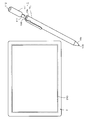
- FIG. 1 is a diagram showing an outline of an embodiment of an authentication system according to the present invention.
- the authentication system of this embodiment comprises an electronic pen 1 and an electronic device 2.
- the electronic pen 1 of this embodiment is configured by combining an electronic pen main body 10 (hereinafter referred to as an electronic pen main body 10) and a pickup 11.
- the electronic pen main body portion 10 has a power supply voltage generation portion, and has a configuration of a so-called active electrostatic system in which a position detection signal is supplied to a sensor portion of the electronic device 2 by electrostatic coupling.
- the power supply voltage generation unit is configured by a battery that can be charged by an electromagnetic induction method or the like in this example.
- the battery may be a primary battery.
- the electronic pen main body 10 is not limited to the configuration of the active electrostatic system, and may be a passive electrostatic capacitance system or an electromagnetic induction system.
- the pickup unit 11 is configured to be removable from the electronic pen main body 10 as a unit (adapter) separate from the electronic pen main body 10.
- the pickup unit 11 is configured to be connected to and coupled to a rear end portion 10b in the axial direction opposite to the pen tip portion 10a side of the electronic pen main body portion 10 in this example by a USB (Universal Serial Bus) It is done.
- USB Universal Serial Bus
- the USB connector jack 106 is provided at the rear end 10 b of the electronic pen main body 10, and the USB connector plug 111 is provided at the pickup 11. Then, the USB connector plug 111 of the pickup unit 11 is inserted into the USB connector jack 106 of the electronic pen main body unit 10, whereby the electronic pen main body unit 10 and the pickup unit 11 are physically and electrically coupled. Be done.
- the pickup unit 11 does not have a battery, and receives the supply of the power supply voltage from the battery of the electronic pen main body unit 10 through the USB connection unit.
- the pickup unit 11 has a function of picking up color information in this example as authentication information and transmitting the information to the electronic device 2. That is, the rear end portion of the pickup unit 11 is pressed against a portion that exhibits an arbitrary color of the predetermined plane portion in a state where the axial center direction of the electronic pen main body portion 10 is perpendicular to the predetermined plane portion At the same time, as described later, the pickup unit 11 is configured to pick up the color of the portion of the flat portion being pressed, and to transmit the information of the picked up color to the electronic device 2.
- the electronic device 2 is configured by a thin and small pad type personal computer.
- the electronic device 2 includes various application programs and has a function to perform various information processing, and in this example, a position detection sensor that interacts with the electronic pen 1 and uses the electronic pen 1 as an operation input device It can be used.
- the electronic device 2 has a function of performing security protection of an authentication target such as an application program or a data file, using the color information sent from the pickup unit 11 of the electronic pen 1 as authentication information.
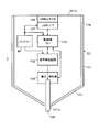
- FIG. 2 is a view showing an example of the configuration of the electronic pen main body 10 according to this embodiment.
- the electronic pen main body unit 10 includes a battery BT as an example of a power supply voltage generation unit, a signal generation circuit 102, and an IC (Integrated Circuit) in a hollow portion of a cylindrical casing 101. And a writing pressure detection unit 104. Further, the core 105 made of a conductor is disposed so that the tip of the pen tip 10 a protrudes from the opening 101 a on the side of the pen tip 10 a in the axial center direction of the housing 101. The other side is coupled to the writing pressure detection unit 104 and disposed in the housing 101 of the electronic pen main body unit 10.
- a USB connector jack 106 is provided at the opening 101b of the rear end 10b opposite to the pen tip 10a of the housing 101 in the axial direction.
- the USB connector jack 106 is connected to the control unit 103 through the USB interface 107.
- the power supply voltage from the battery BT is supplied to the pickup unit 11 connected to the USB connector jack 106 through the USB interface 107 and the USB connector jack 106.
- the signal generation circuit 102 supplies a position detection signal to the core 105 according to the control of the control unit 103.
- the electrostatic capacitance coupling between the core 105 of the electronic pen main body 10 of the electronic pen 1 and the position detection sensor of the electronic device 2 causes the signal from the core 105 of the electronic pen main body 10 to detect the position of the electronic device 2 Received by
- the capacitive coupling between the core 105 of the electronic pen main body 10 and the position detecting sensor of the electronic 2 is Through interaction, the position detection signal sent from the core 105 is received by the position detection sensor of the electronic device 2, and the position pointed by the core 105 of the electronic pen body 10 in the electronic device 2 as described later Position coordinates on the position detection sensor are detected.
- the control unit 103 generates writing pressure information corresponding to the writing pressure value detected by the writing pressure detection unit 104 and supplies the writing pressure information to the signal generation circuit 102.
- the signal generation circuit 102 supplies the pen pressure information to the core body 105 by supplying a position detection signal and the signal to the core 105 by, for example, a time division multiplex system, a frequency multiplex system, or another signal multiplex system. Is configured as.
- the signal generation circuit 102 transmits a position detection signal as a burst signal, modulates the pen pressure information as digital information, and modulates it into an on-off keying (OOK) signal or an amplitude shift keying (ASK) signal. It may be configured to deliver.
- OOK on-off keying
- ASK amplitude shift keying
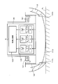
- FIG. 3 is a view showing a configuration example of the pickup unit 11 of this embodiment.
- FIG. 3 shows the rear end side of the pickup 11 downward
- FIG. 3A shows a state in which the rear end of the pickup 11 is free and not blocked.
- FIG. 3B shows a state in which the rear end of the pickup 11 is pressed against an arbitrary flat portion FL, and the opening of the rear end of the pickup 11 is closed.
- the pickup unit 11 is connected to the opening 112a of the cylindrical casing 112 on the side of connection with the electronic pen main unit 10, and in this example, the USB connector plug 111 is Prepare.
- a lens 113 is disposed in the opening 112 b of the rear end of the hollow portion of the housing 112 of the pickup unit 11 opposite to the side coupled with the electronic pen main body 10 in the axial direction.
- a color detection component including the lens 113 as a component is disposed inside the lens 113.
- the USB interface 115 disposed on the printed circuit board 114, the control unit 116, the power supply circuit 117, the wireless communication unit 118, and the memory 119 are disposed in the hollow portion of the housing 112 of the pickup unit 11. It is done.
- the wireless communication unit 118 is configured by a short distance wireless communication method, for example, a wireless communication unit of Bluetooth (registered trademark) standard.
- the wireless communication unit 118 is not limited to the wireless communication means using such radio waves, and for example, an optical communication means using infrared rays or the like can also be used.
- the USB interface 115 supplies the power supply voltage from the battery BT of the electronic pen main body 10 to the power supply circuit 117 when the electronic pen main body 10 and the pickup 11 are connected by USB.
- the power supply circuit 117 generates a power supply voltage for each unit of the pickup unit 11, supplies the power supply voltage to each unit of the control unit 116, the wireless communication unit 118, and the memory 119, and constitutes a color detection configuration unit.
- the power supply voltage is supplied to the light receiving unit 122, the color detection circuit 123, and the pressure detection switch 124.
- the control unit 116 controls the memory 119 to store the information of the color picked up and generated by the color detection configuration unit as described later and to transmit the information to the electronic device 2 through the wireless communication unit 118.
- the control unit 116 also has a function of controlling the operation of the color pickup by the color detection configuration unit.
- the color detection configuration unit is an LED (Light Emitting Diode) as an example of the light emitting element 121, a light receiving unit 122, a color detection circuit 123, a pressing detection switch 124, and a holder 125. And is configured.
- LED Light Emitting Diode
- the light receiving unit 122 and the color detection circuit 123 are unitized and housed in a case 126, and the case 126 is disposed behind the lens 113. It is arranged to be movable together with the lens 113. In this case, the case 126 is disposed behind the lens 113 in a state in which the light receiving unit 122 can receive the light collected by the lens 113.
- the light receiving unit 122 includes optical filters Fr, Fg, and Fb that transmit only red light, green light, and blue light, and the optical filters Fr, Fg, and Fb, respectively.
- the phototransistors PTr, PTg, and PTb receive the transmitted red light, green light, and blue light, respectively. Then, light reception output signals of the phototransistors PTr, PTg, and PTb are supplied to the color detection circuit 123.
- the color detection circuit 123 generates color information from light reception output signals corresponding to respective light reception levels of red light, green light, and blue light from the phototransistors PTr, PTg, and PTb of the light receiving unit 122. For example, the color detection circuit 123 converts the light reception output signals of red light, green light, and blue light into digital signals Dr, Dg, Db of a plurality of bits corresponding to the respective signal levels, for example, 8 bits. Further, lightness information (brightness information) indicating brightness is also generated from the light reception output signal as, for example, an 8-bit digital signal Y, and is configured as color information together with the digital signals Dr, Dg, Db. In this embodiment, the color detection circuit 123 generates color information of the L * a * b * color system which is obtained by mathematical conversion from the digital signals Dr, Dg, Db and Y.
- the color information generated by the color detection circuit 123 is not limited to the information of colors in the L * a * b * color system, and RGB using the three primary colors of red light, green light, and blue light. Color information of a color system may be used, or color information of an L * u * v * color system or another color system may be used.
- the holder portion 125 is disposed on the rear end portion side in the hollow portion of the housing 112 of the pickup portion 11 so as not to move in the axial direction.
- a concave portion 125 a having an opening at the lens 113 side is provided at a central portion of the holder portion 125, and a pressure detection switch 124 is disposed at the bottom of the concave portion 125 a.
- the pressure detection switch 124 is provided with a pressure element 124a. When the pressure element 124a is not pressed, the pressure detection switch 124 is turned off, and when the pressure element 124a is pressed, it is turned on. It is configured. Further, in this embodiment, the pressure detection switch 124 is disposed in the concave portion 125 a of the holder portion 125 in a state where the pressing element 124 a protrudes toward the lens 113 side. The pressure detection switch 124 is connected to the control unit 116, and the control unit 116 has a function of monitoring the switch state of the pressure detection switch 124.
- a case 126 which accommodates the light receiving unit 122 and the color detection circuit 123 and is attached to the rear side of the lens 113 is provided to face the pressing element 124 a of the pressure detection switch 124.
- the case 126 is smaller than the inner diameter of the recess 125 a of the holder portion 125, and therefore, the case 126 can move in the direction in which the pressing element 124 a is pressed.
- a plurality of light emitting elements (LEDs) 121 are arranged around the opening on the lens 113 side of the concave portion 125 a of the holder portion 125.
- the plurality of light emitting elements 121 are configured to be controlled to be turned on and off by a control signal from the control unit 116.
- the plurality of light emitting elements 121 are disposed, for example, at equal intervals around the opening on the lens 113 side of the concave portion 125 a of the holder portion 125.
- the number of light emitting elements 121 may be one for picking up a color, but by configuring as in this example, as shown in FIG. 3B, the pickup unit 11 is pushed by the flat portion FL.
- the emitted light is emitted to the flat portion FL through the lens 113, and light reflected from the flat portion FL can be uniformly incident on the light receiving surface of the light receiving portion 122 through the lens 113. Ru.
- the lens 113 is always biased toward the opening 112 b of the housing 112 between the end surface of the holder portion 125 on the lens 113 side and the rear surface of the lens 113.
- An elastic member in this example, a coil spring 127, is disposed as shown in FIG. 3 and FIG.
- the lens 113 is stepped by the opening 112b of the housing 112 by the elastic force of the coil spring 127.
- the opening 112 b of the housing 112 is closed by the lens 113 by being pressed against the portion 112 c.
- the lens 113 side of the pickup unit 11 is pressed against the flat surface portion FL as shown in FIG. 3B, the lens 113 resists the elastic force of the coil spring 127 and the lens 113 picks up It is pushed into the inside of the case 112 of the part 11. Then, with the sliding movement of the lens 113 to the inside of the housing 112 of the pickup unit 11, the case 126 moves in the axial direction, and presses the pressing element 124 a of the pressing detection switch 124. As a result, the pressure detection switch 124 changes from the off state to the on state.
- the control unit 116 of the pickup unit 11 detects that the pressure detection switch 124 has changed to the on state, and detects that the rear end of the pickup unit 11 is pressed against the flat surface portion FL. Then, based on the detection of the on state of the pressure detection switch 124, the control unit 116 controls all of the plurality of light emitting elements 121 from the light off state to the on state.
- the light emitted from the plurality of light emitting elements 121 is emitted to the portion of the flat portion FL corresponding to the opening 112 b at the rear end portion of the pickup unit 11.
- part is incident on the light-receiving part 122 through the lens 113 from the site
- the pickup unit 11 When the rear end of the pickup unit 11 is pressed against the flat portion FL by forming the casing 112 of the pickup unit 11 with an elastic body such as resin or rubber capable of elastic deformation, the pickup unit The degree of adhesion between the circumferential tip of the opening 112b on the side of the lens 113 and the flat portion FL can be increased.
- an elastic ring may be provided in the opening 112 b so as to fit in the outer peripheral portion of the lens 113 and to protrude in a direction along the axial center direction of the housing 112 more than the lens 113.
- the light receiving unit 122 divides the incident light into the red light component, the green light component, and the blue light component, and receives the light according to the light receiving level of each component.
- the color detection circuit 123 generates information on the color of the L * a * b * color system from the light receiving output from the light receiving unit 122.
- the color information generated by the color detection circuit 123 is stored in the memory 119 under the control of the control unit 116.
- the control unit 116 transmits the color information stored in the memory 119 to the electronic device 2 through the wireless communication unit 118.
- the control unit 116 confirms completion of transmission of color information (completion of reception by the electronic device 2) by communication with the electronic device 2 through the wireless communication unit 118, the transmission is stopped and stored in the memory 119. Erase the color information.
- matching detection is performed by matching the registered color information (authentication reference information) with the picked-up color information (authenticated information) Whether or not authentication is possible is determined, but by changing the threshold value determined to match, it is possible to determine that the information of both colors match, even if slightly different. It is because it can.
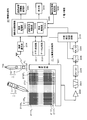
- the electronic device 2 interacts with the electronic pen main body 10 by electrostatic coupling to detect the position designation input instructed by the pen tip 10 a of the electronic pen main body 10.
- a position detection processing unit 21 including a position detection sensor 210 for the purpose, and an information processing unit 20 for performing various information processing.
- the position detection processing unit 21 of the electronic device 2 receives the position detection signal from the electronic pen main body 10 through the position detection sensor 210, and the position detection sensor 210 instructed by the pen tip 10 a of the electronic pen main body 10 is received. Detect the position.
- the position detection sensor 210 is formed by laminating a first conductor group and a second conductor group via an insulating layer.
- the first conductor group separates a plurality of first conductors 211Y 1 , 211Y 2 ,..., 211Y m (m is an integer of 1 or more) extending in the lateral direction (X-axis direction) from each other by a predetermined distance in parallel , Arranged in the Y-axis direction.
- the second conductor group extends in a direction intersecting the extending direction of the first conductors 211Y 1 , 211Y 2 ,..., 211Y m , in this example, in the vertical direction (Y-axis direction) orthogonal to the extending direction.
- a plurality of second conductors 212X 1 , 212X 2 ,..., 212X n (n is an integer of 1 or more) are arranged in parallel in the X-axis direction with a predetermined interval therebetween.
- a selection circuit 221 serving as an input / output interface is provided between the position detection sensor 210 and the position detection control circuit 227 of the position detection processing unit 21. Selection circuit 221 is controlled to select one conductor each in the present example from the first conductor group and the second conductor group based on the control signal from position detection control circuit 227. .
- the position detection processing unit 21 is input from the conductor of the position detection sensor 210 selected by the selection circuit 221 according to a control signal from the position detection control circuit 227.
- the transmission signal composed of the modulation signal of the sine wave signal from the electronic pen 1 is amplified by the amplification circuit 222 and supplied to the band pass filter 223 so that only the frequency component of the sine wave signal is extracted. Be done.
- the output signal of the band pass filter 223 is detected by the detection circuit 224, and the detection output signal is sampled and held at a predetermined timing by the sampling signal from the position detection control circuit 227 by the sample hold circuit 225, and then the AD conversion circuit. Converted to digital value by 226. Digital data from the AD conversion circuit 226 is supplied to the position detection control circuit 227.
- the position detection control circuit 227 calculates position coordinates on the position detection sensor 210 designated by the electronic pen 1 from the digital data.
- the pen pressure information detected by the pen pressure detection unit 104 is transmitted from the electronic pen 1 to the position detection sensor 210 in a time division state with the position detection signal.
- the position detection control circuit 227 of the position detection processing unit 21 detects a pen pressure value from the pen pressure information. Then, the position detection control circuit 227 supplies information on position coordinates on the position detection sensor 210 indicated by the detected electronic pen 1 and the writing pressure value to the information processing control unit 200 of the information processing unit 20.
- the information processing unit 20 causes the information processing control unit 200 to store an application storage unit 201 that stores one or more application programs, characters and symbols input by the position detection sensor 210 by the electronic pen 1.
- a data storage unit 202 for storing files and folders of drawing information such as figures and pictures drawn on the position detection sensor 210 by the electronic pen 1;
- a communication unit 204, an authentication reference information storage unit 205, and a writing color information storage unit 206 are connected.
- the display unit 203 is configured by an LCD (Liquid Crystal Display) in this example.
- the wireless communication unit 204 is configured to be capable of communicating with the wireless communication unit 118 of the pickup unit 11 of the electronic pen 1, and in this example, is configured by a wireless communication unit of Bluetooth (registered trademark) standard.
- the authentication reference information storage unit 205 stores in advance authentication reference information in which color information is associated with an authentication target, and when an authentication request is made, the electronic pen 1 A buffer area is provided to store the transmitted color information for comparison and comparison with the authentication reference information.
- the authentication reference information is information registered in advance and referred to in order to determine whether or not the information to be authenticated matches when the authentication process is performed.
- the writing color information storage unit 206 stores information of the writing color when the electronic pen 1 inputs a writing by the position detection sensor 210 of the electronic device 2. In this embodiment, as will be described later, the color information sent from the electronic pen 1 is stored as writing color information.
- the information processing control unit 200 is configured by a microprocessor formed of an IC (Integrated Circuit).
- the information processing control unit 200 includes functional units of a registration processing unit 2001 for authentication reference information, an authentication possibility determination unit 2002, a display control unit 2003, and other functional units. Each functional unit is configured to be executed using an application program stored in the unit 201.
- the registration processing unit 2001 designates, of the application storage unit 201, an application program that requires an authentication process that can be used only when authentication is successful, and registers authentication reference information for the authentication process. And processing for storing in the authentication reference information storage unit 205.
- the authentication reference information uses, in this example, the color information described above.
- the authentication possibility determination unit 2002 compares the registered authentication reference information with the color information sent from the electronic pen 1 to determine whether the authentication is possible. When the matching degree between the color information of the registered authentication reference information and the color information of the to-be-authenticated information sent from the electronic pen 1 is equal to or higher than a predetermined threshold, authentication is successful (authentication OK). If it is determined that the degree of coincidence does not meet the predetermined threshold value, it is determined that the authentication could not be performed (authentication NG).
- the determination of the matching degree between the registered color information of the authentication reference information and the color information of the to-be-authenticated information sent from the electronic pen 1 is performed by calculating the difference between the two color information If the difference exceeds the threshold, the authentication is OK, and if the difference is less than the threshold, the authentication is NG.
- the value of this threshold is determined in consideration of the fact that the color may change slightly depending on the external environment such as the time, place, and temperature to be detected and the use condition of the pickup unit 11.
- the threshold is set so that it can be determined as a match if it is not a physical match but a predetermined similarity range.
- the setting of the threshold value can also be used for security strength. That is, in order to make security strictly (strong), the threshold value is selected to be a value between 0 and a minute value between the color information of the registered authentication reference information and the color information of the authentication information. When the security is relatively weak, the threshold is selected to be a value to which the difference is relatively large. That is, when the range of the degree of color matching is narrow, it can be considered as a system with strong security, assuming that only colors close to perfect matching are recognized. On the other hand, if the degree of color matching is wide, the system can be weak in security.
- the information processing control unit 200 Based on the authentication determination result of the authentication possibility determination unit 2002, the information processing control unit 200 performs a control operation as an authentication target associated with the authentication reference information, that is, a control as to whether or not to start an application program. And open files and folders to control whether to allow the use of data.
- the display control unit 2003 executes a display function of each application program to control to display a display image on the display screen 203D (see FIG. 1) of the display unit 203.
- the pen of the electronic pen 1 Display the previous writing mark in color.
- the user requests the electronic device 2 to register the writing color, and the pickup unit 11 of the electronic pen 1 performs a color pickup operation to The information is configured to be able to be transmitted to the electronic device 2.
- the electronic device 2 stores the color information received from the pickup unit 11 of the electronic pen 1 in the writing color information storage unit 206, and the position detection sensor by the electronic pen 1 thereafter It is configured to be used as a display color for writing input on the screen 210.
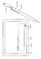
- the user When picking up color information, the user places the rear end side of the pickup unit 11 in white, with the pen tip 10a side up as shown in the upper center of FIG. , Etc., it is pressed against the portion of the flat portion FL which is exhibiting the color which oneself wants to pick up. At this time, the user presses the rear end side of the pickup unit 11 against the flat portion FL so that the axial center direction of the housing 101 of the electronic pen 1 is in the flat portion FL and is vertical.
- the lens 113 at the rear end of the pickup unit 11 is pushed into the inside against the elastic force of the coil spring 127, and the pickup unit The end face of the opening 112 b at the rear end of the housing 112 is pressed against the flat portion FL, and the outside light does not enter into the opening 112 b. Then, as the lens 113 is pushed inward against the elastic force of the coil spring 127, the press detection switch 124 changes from the off state to the on state, and the pickup operation of the color information by the pickup unit 11 is activated. Be done.
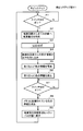
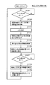
- the control unit 116 of the pickup unit 11 of the electronic pen 1 monitors whether or not the press detection switch 124 has been turned on (step S1).
- the control unit 116 controls the power supply circuit 117 to supply the power supply voltage to all the circuit units in the pickup unit 11.
- Step S2 The plurality of LEDs 121 are all turned on, and the light receiving unit 122 and the color detection circuit 123 are made operable (Step S3).
- the light receiving unit 122 divides the reflected light into the red light component, the green light component, and the blue light component and receives the light reception output according to the light reception level of each component Are output to the color detection circuit 123.
- the color detection circuit 123 generates information on the color of the L * a * b * color system from the light reception output from the light receiving unit 122.
- step S3 the control unit 116 takes in the color information generated by the color detection circuit 123 (step S4), and temporarily holds the information in the memory 119 (step S5). Then, the control unit 116 transmits the information on the color temporarily stored in the memory 119 to the electronic device 2 through the wireless communication unit 118 (step S6).
- the predetermined time at this time is a time sufficient for picking up the color information from the flat surface portion FL by the pickup unit 11 and transmitting the information to the electronic device 2, and is, for example, several seconds or more.
- a status notification display element such as an LED (Light Emitting Diode) is provided in the casing 112 of the pickup unit 11 so that the user can check whether the light emitting element 121 is on or off.
- the state notification light emitting element may be turned on.
- the press detection switch 124 changes from the on state to the off state.
- the control unit 116 of the pickup unit 11 of the electronic pen 1 monitors that the pressure detection switch 124 changes from the on state to the off state (step S7), and the pressure detection switch 124 changes from the on state to the off state When it is determined, the color information stored in the memory 119 is erased (step S8), and the supply state of the power supply voltage from the power supply circuit 117 to each circuit is returned to the standby state (step S9). Then, after step S9, the control unit 116 returns the process to step S1 and repeats the processes after step S1.
- the memory 119 is configured of a volatile memory, and the supply of the power supply voltage from the power supply circuit 117 supplied to the memory is stopped. You should do it. It goes without saying that when the memory 119 is composed of a non-volatile memory, the control unit 116 erases the color information.
- the user previously registers color information to be used for authentication for each object to be authenticated using color information.
- the registered color information is information for authentication reference in the case of judging whether or not the authentication of the authentication target is possible.
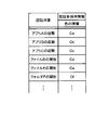
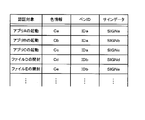
- each activation of application programs A, B and C is registered as an authentication target, and information Ca, Cb and Cc of different colors are registered for each authentication target, and files
- Each opening of D, E and folder F is registered as an authentication target, and information Cd, Ce, Cf of different colors is registered for each authentication target.
- Correspondence information (correspondence table information) between the authentication target and the authentication reference information in the example of FIG. 7 is stored and held in the authentication reference information storage unit 205 shown in FIG.
- the authentication target is not limited to the example shown in FIG.
- the operation activation of the electronic device 2 at the time of power activation may be an authentication target, and the operation of the electronic device 2 may be activated when the authentication by the color information is OK.
- the color information registered as authentication reference information is shown as being different for each authentication target, but even if the authentication target is different, color information obtained by picking up the same color is used. Needless to say, it may be used.
- the electronic device 2 can start the execution of the security function for the authentication target.
- the electronic device 2 specifies an authentication target, and color information which is authentication reference information stored in the authentication reference information storage unit 205 in association with the specified authentication target. And the color information as the authentication information sent from the pickup unit 11 of the electronic pen 1 at the time of the authentication (at the time of execution of the security function), and whether authentication is possible or not based on the comparison result. To judge. Then, only when the authentication is OK, when the authentication target is an application program, it can be started, and when the authentication target is a file or a folder, it can be opened and data can be used. It becomes. Further, in the case where the authentication target is, for example, operation activation at the time of power activation of the electronic device 2, when the authentication by the color information becomes OK, the electronic device 2 can start the operation.
- the user uses the pickup unit 11 of the electronic pen 1 to compare color information as authentication information to make it possible to determine whether or not authentication is possible in comparison with authentication reference information. To pick up.
- the pickup unit 11 of the electronic pen 1 picks up the color information and transmits it to the electronic device 2. Then, the electronic device 2 executes authentication processing for security, determines whether or not authentication is possible, and determines whether or not to use an authentication target according to the determination result.
- the electronic device 2 of this embodiment is configured to have a function capable of registering a writing color. That is, at the time of registration of the writing color, information of the color picked up by the pickup unit 11 of the electronic pen 1 and wirelessly transmitted is acquired and held in the writing color information storage unit 206. Then, a writing trace by writing input on the position detection sensor 210 by the electronic pen 1 is displayed in color on the display screen of the display unit 203 using the color information stored in the writing color information storage unit 206. .
- a line drawing such as characters and figures but also a type of pen tip of the electronic pen 1 can be designated by the electronic device 2 as a writing trace by the handwriting input in this case, a painting brush for painting It also includes a drawing mark by something like a brush or a brush.
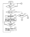
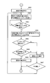
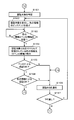
- the information processing control unit 200 first determines whether any processing event has occurred based on the input operation of the user (step S11). If it is determined in step S11 that some processing event has occurred, the information processing control unit 200 first determines whether the processing event is “registration for authentication” (step S12).
- step S12 When it is determined in this step S12 that the "registration for authentication" is made, the information processing control unit 200 specifies an authentication target based on the occurrence status of the processing event in step S11 (step S13).
- step S13 for example, an instruction indicating registration of authentication reference information for starting an application program specified or specified at the time of the process event determined in step S11 is performed. If it contains, the authentication target is the activation of the application program.
- the processing event includes an instruction that means registration of authentication reference information for opening a file or folder
- the authentication target is opening of the file or folder.
- the information processing control unit 200 holds the information of the authentication target specified in step S13, and urges the user to pick up color information as authentication reference information (step S14).
- the user who responds to the prompt in step S14 has the color that he / she wants to use as the authentication reference information, as described with reference to FIG. 6, the rear end side of the pickup unit 11 of the electronic pen 1 The flat part FL is pressed. Then, as described above, since color information is wirelessly transmitted from the pickup unit 11 of the electronic pen 1, the electronic device 2 receives the information of the color through the wireless communication unit 204.
- the information processing control unit 200 of the electronic device 2 waits for the user to receive the color information according to the prompt (step S15). If it is determined in step S15 that the reception of the color information has been confirmed, the information processing control unit 200 displays the authentication target information identified in step S13 and the received color information as shown in FIG. The table information stored in the authentication reference information storage unit 205 is stored as table information associated with (step S16). Then, the information processing control unit 200 returns the process to step S11 and repeats the processes after step S11.
- step S12 determines whether the processing event that has occurred requires “authentication” (step S17). .
- step S17 it is determined whether the process event determined in step S11 relates to the authentication target stored in the authentication reference information storage unit 205 and requires authentication.
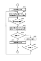
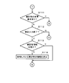
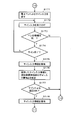
- step S17 If it is determined in step S17 that "authentication" is requested, the information processing control unit 200 determines the authentication target based on the processing event generated in step S11 and the storage information of the authentication reference information storage unit 205. The target of is identified (step S21 of FIG. 9).
- the information processing control unit 200 holds the identified information to be authenticated and urges the user to pick up the color information as the information to be authenticated for executing the authentication (step S22).
- the user who responds to the prompt in step S22 is, as described with reference to FIG. 6, information on the color registered for the rear end side of the pickup unit 11 of the electronic pen 1 with respect to the authentication target specified by the user.
- the operation is performed to press the flat portion FL which exhibits the same color as the registered color.
- the color information is transmitted wirelessly from the pickup unit 11 of the electronic pen 1, so the electronic device 2 uses the information on the color as the authentication information through the wireless communication unit 204. To receive.
- the information processing control unit 200 of the electronic device 2 waits for the user to receive the color information according to the prompt (step S23). If it is determined in step S23 that the reception of the color information has been confirmed, the information processing control unit 200 stores the color information as the authentication information received in step S23 and the authentication reference information storage unit 205. The color information of the authentication reference information stored in association with the authentication target specified in step S22 is compared (step S24), and it is determined whether the authentication is OK (step S24). Step S25).
- steps S24 and S25 whether or not authentication is possible is determined based on whether the color information stored in the authentication reference information storage unit 205 matches the color information received in step S23. That is, as described above, the difference between the color information of the authentication reference information and the information of the color of the information to be authenticated is calculated, and if the difference is equal to or less than the threshold, it is determined that authentication is OK, and the difference is the threshold When it exceeds, it is determined that it is authentication NG.
- step S25 If it is determined in this step S25 that the authentication is not OK but the authentication is NG, the information processing control unit 200 displays the authentication NG on the display screen of the display unit 203 and emits an alarm sound, etc. To the person (step S26). Then, after the step S26, the information processing control unit 200 inquires whether or not to perform the authentication again, and determines the reply from the user (step S27). If it is determined in step S27 that the response to redo is obtained, the information processing control unit 200 returns the process to step S22, and repeats the process from step S22. If it is determined in step S27 that an answer not to perform again is obtained, the information processing control unit 200 returns the process to step S11 of FIG. 8 and repeats the process of step S11 and subsequent steps.
- step S25 If it is determined in step S25 that the authentication is OK, the information processing control unit 200 releases the security protection and permits the authentication target (step S28). What is permitted in step S28 is activation of an application program to be authenticated and opening of a file or folder to be authenticated. Then, the information processing control unit 200 returns the process to step S11 in FIG. 8 and repeats the processes after step S11.
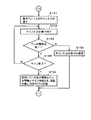
- step S31 of FIG. 10 determines whether the processing event is “registration of writing color”. It discriminate
- the determination in step S31 is, for example, when the processing event generated in step S11 is a handwriting input on the position detection sensor 210 of the electronic device 2 by using, for example, the electronic pen 1. This processing is performed depending on whether or not the processing event is based on clicking on the “registration of written color” icon displayed on the display screen of the electronic device 2.
- step S31 If it is determined in step S31 that "registration of writing color" is not performed, the information processing control unit 200 executes other processing for the processing event (step S32), and then the processing is performed in step S11 of FIG. Then, the process after step S11 is repeated.
- step S31 When it is determined in step S31 that the processing event is "registration of writing color", the information processing control unit 200 prompts the user to pick up information of color as writing color information (step S33).
- the user who responds to the prompt in step S33 exhibits the color he / she wants to use as the authentication reference information, as described with reference to FIG. 6, the rear end side of the pickup unit 11 of the electronic pen 1 The flat part FL is pressed. Then, as described above, since color information is wirelessly transmitted from the pickup unit 11 of the electronic pen 1, the electronic device 2 receives the information of the color through the wireless communication unit 204.
- the information processing control unit 200 of the electronic device 2 monitors the reception of the color information by the user in response to the prompt (step S34), and the color information If it is determined that it has been received, the received color information is stored as writing color information in the writing color information storage unit 206 (step S35).
- the electronic device 2 can receive writing input from the electronic pen 1 through the position detection sensor 210. It is configured. Therefore, from the state where the rear end of the pickup unit 11 is pressed against the flat portion FL, the user shown the electronic pen 1 at the center of FIG. The input area of the position detection sensor 210 is moved close to or in contact with the second position detection sensor 210 to change to a state where a handwriting input is performed.
- step S35 the information processing control unit 200 determines whether or not the handwriting input by the electronic pen 1 is detected based on whether or not a signal having a predetermined level or more is received from the electronic pen 1 through the position detection sensor 210. Then (step S36), the handwriting input is monitored. Then, when it is determined that the handwriting input is detected in step S36, the information processing control unit 200 stores the coordinate information of the detected locus of the handwriting input (step S37), and is stored in the handwriting color information storage unit 206. The locus of the handwriting input is displayed in color on the display screen of the display unit 203 using the color information (writing color information) (step S38).
- step S39 determines whether or not the user has made a change request for the writing color
- step S40 determines whether the writing input has ended. If it is determined, the process returns to step S36, and the processes after step S36 are repeated.
- step S40 When it is determined in step S40 that the handwriting input is completed, the information processing control unit 200 deletes the information of the color of the handwritten color stored in the handwritten color information storage unit 206 (step S41), and then, The process returns to step S11 of FIG. 8 to repeat the processes after step S11.
- authentication of an authentication target is performed using information of a color picked up by the pickup unit 11 coupled to the electronic pen main body unit 10. Can.
- the user only needs to press the rear end portion of the pickup portion 11 coupled to the rear end side of the electronic pen main body portion 10 against a flat portion presenting a color desired for authentication. So easy to use.
- the user since the information of the color picked up by the pickup unit 11 is used for the authentication, the user may store the color used for the authentication. For this reason, compared with the case where a multi-digit number, a symbol, etc. are used for authentication, the risk of forgetting information for authentication can be reduced.
- the user only needs to press the rear end of the pickup unit 11 against the flat portion exhibiting the color used for authentication as the input operation of the information for authentication. There is also an advantage that input operation errors as in the case of inputting numbers, symbols and the like are unlikely to occur, and input operations are easy.
- information on the color picked up by the pickup unit 11 can be used as the display color of the writing mark of the writing input in the position detection sensor 210 by the electronic pen 1.
- the display color of the writing mark can be used as it is because the information of the color picked up by the pickup unit 11 can be used as it is, so that the writing mark can be represented by a color intended by the user, which is convenient.
- the coordinate information of the handwriting input stored in the electronic device 2 may be stored in association with the information of the color stored in the handwriting color information storage unit 206.
- the color information transmitted from the pickup unit 11 of the electronic pen 1 changes the storage unit, and the color information as authentication reference information and the color as authentication information Information of color, and information of color as writing color information are distinguished, but an index for identifying each for authentication reference, authentication and writing color is added as additional information, and each color is added. It is of course possible to store information of
- the transmission of the color information picked up by the pickup unit 11 to the electronic device 2 is performed from the wireless communication unit 118 included in the pickup unit 11.
- the wireless communication unit is provided in the electronic pen main body unit 10, and the control unit 103 of the electronic pen main body unit 10 receives color information from the pickup unit 11 through the USB interface 107. May be acquired and transmitted using the wireless communication unit provided in the electronic pen main body unit 10.
- the control unit 103 of the electronic pen main body unit 10 acquires color information from the pickup unit 11 through the USB interface 107 and transmits the information through the core 105. And may be supplied to the position detection sensor 210, and may be transmitted to the electronic device 2 by interaction between the electronic pen main body 10 and the position detection sensor 210.
- the pickup unit 11 is connected to the electronic pen main body 10 of the electronic pen 1 by USB and configured to receive a power supply voltage from the electronic pen main body 10.
- a battery (which may be a primary battery or a secondary battery) may be provided in the housing 112 of the pickup unit 11.
- the pickup unit 11 and the electronic pen main body unit 10 do not need to be electrically connected. , Just be able to combine. Then, at the time of picking up color information by the pick-up unit 11, the pick-up unit 11 can be removed from the electronic pen main body 10 and pressed against the flat portion FL to perform a pick-up operation.
- the pressing detection switch detects the pressing due to the movement of the lens as a configuration in which the lens is pushed and moved when the rear end of the pickup unit is pressed against the flat portion. So, I started the pickup unit.
- the pressing detection switch detects the pressing due to the movement of the lens as a configuration in which the lens is pushed and moved when the rear end of the pickup unit is pressed against the flat portion. So, I started the pickup unit.
- it is not limited to such a configuration.
- the rear end portion of the pickup unit is provided with a skirt portion made of an elastic material such as silicone rubber so as to protrude outward in the axial direction of the pickup unit from the peripheral portion of the lens.
- a skirt portion made of an elastic material such as silicone rubber so as to protrude outward in the axial direction of the pickup unit from the peripheral portion of the lens.
- a contact sensor for detecting contact with the flat surface and a pressure sensor for detecting pressing force from the flat surface are provided in a housing portion at the rear end of the pickup unit, and detection of those contact sensors and pressure sensors
- the pickup unit may be activated based on the output to light the LED.
- the configuration as the authentication system includes the electronic pen and the electronic device described with reference to FIG. 1 in the first embodiment, but the authentication reference information includes only color information. This is a case where the security can be made stronger by using identification information of the electronic pen (hereinafter referred to as pen ID information) instead.
- the authentication system according to the second embodiment differs from the electronic pen 1 according to the first embodiment in the electronic pen 1A having a storage unit for storing pen ID information, and the electronic device 2 according to the first embodiment. It consists of the electronic device 2A which differs in the configuration of the processing function related to the authentication processing.
- the electronic pen 1A according to the second embodiment includes an electronic pen main body 10A (see FIG. 11) and a pickup 11A (not shown).
- the hardware configuration of the electronic pen main body portion 10A of the electronic pen 1A of the second embodiment is the same as that of the electronic pen 1 of the first embodiment in terms of control processing contents with the control unit 103, as shown in FIG.
- a different point is that a pen ID memory 108 is connected to the control unit 103A as well as having a different control unit 103A.
- the pen ID memory 108 stores pen ID information for identifying each electronic pen 1A.
- the other configuration of the electronic pen main body 10A is the same as that of the electronic pen main body 10 of the electronic pen 1 of the first embodiment shown in FIG. In FIG. 11, the same parts as those of the electronic pen main body 10 of the electronic pen 1 according to the first embodiment are denoted by the same reference numerals.
- the pickup unit 11A of the electronic pen 1A according to the second embodiment is not shown, but as the hardware configuration, the control unit 116 of the pickup unit 11 of the electronic pen 1 according to the first embodiment has control contents.
- the configuration is the same as that of the pickup unit 11 of the electronic pen 1 of the first embodiment described with reference to FIGS. 3 and 4 except that a control unit 116A (not shown) different from the above is included.
- the hardware configuration of the electronic device 2A of the second embodiment is different from the information processing control unit 200A of the information processing control unit 200 of the electronic device 2 of the first embodiment shown in FIG. Not shown), and an authentication reference information storage unit 205A (not shown) whose authentication reference information stored is different from the authentication reference information storage unit 205 of the electronic device 2 of the first embodiment.
- the writing color information storage unit 206 also includes a writing color information storage unit 206A (not shown) that is different from the writing color information stored.
- the other configuration of the electronic device 2A of the second embodiment is the same as that of the electronic device 2 of the first embodiment.
- the pickup unit 11A of the electronic pen 1A presses the rear end portion of the pickup unit 11A against the flat surface unit FL to pick up the color information
- the pickup unit 11 of the first embodiment Similar to the color information pickup operation.
- the control unit 116A of the pickup unit 11A according to the second embodiment temporarily holds the picked-up color information without transmitting it to the electronic device 2A, and temporarily holds the pen ID information. Is sent to the electronic pen main body 10A via the USB interface 115 and the USB connector plug 111.
- control unit 103A of the electronic pen main body 10A of the electronic pen 1A receives the acquisition request for pen ID information from the pickup unit 11A through the USB connector jack 106 and the USB interface 107, the pen ID information read from the pen ID memory 108 is , And transmits to the pickup unit 11A through the USB interface 107 and the USB connector jack 106.
- control unit 116A of the pickup unit 11A When the control unit 116A of the pickup unit 11A according to the second embodiment acquires pen ID information from the electronic pen main body unit 10A, the control unit 116A of the pickup unit 11A transmits the information of the held color and the acquired pen ID information to the wireless communication unit 118. To the electronic device 2 through
- step S51 to step S55 of FIG. 12 are the same as the operations from step S1 to step S5 of FIG. That is, the user presses the rear end side of the pickup unit 11A against the portion of the flat portion FL in which the user wishes to pick up the color with the electronic pen 1A with the pen tip 10a side up. Then, the press detection switch 124 changes from the off state to the on state (step S51), power is supplied to each part of the pickup unit 11A (step S52), the LED 121 is lighted (step S53), and color information An acquisition operation is performed (step S54), and information on the acquired color is temporarily stored in the memory 119 (step S55).
- step S55 the control unit 116A sends an acquisition request of pen ID information to the electronic pen main body unit 10A through the USB interface 115, In response to this, pen ID information sent from the electronic pen main body 10A is acquired through the USB interface 115 (step S56).
- control unit 116A transmits the color information temporarily stored in the memory 119 and the pen ID information acquired from the electronic pen main body unit 10A to the electronic device 2 through the wireless communication unit 118 (step S57).
- step S58 the control unit 116A of the pickup unit 11A of the electronic pen 1A releases the state in which the user presses the rear end side of the electronic pen 1A against the flat surface portion FL, thereby turning the press detection switch 124 from the on state to the off state.
- the change is monitored (step S58), and when it is determined that the pressure detection switch 124 has changed from the on state to the off state, the color information stored in the memory 119 is erased (step S59).
- the supply state of the power supply voltage to each circuit from 117 is returned to the standby state (step S60).
- step S60 the control unit 116A returns the process to step S51, and repeats the processes after step S51.
- the activation of each of the application programs A, B and C is registered as an authentication target, and information Ca of different colors is registered for each authentication target.
- Cb and Cc and pen ID information IDa, IDb and IDc are registered in association with each other.
- the unopened files D and E are registered as authentication targets, and information Cd and Ce of different colors and pen ID information IDd and IDe are registered in association with each other for each authentication target.
- the correspondence information (correspondence table information) between the authentication target and the authentication reference information in the example of FIG. 13 is stored and held in the authentication reference information storage unit 205A, as in the first embodiment.
- the color information is shown as being different for each authentication target, but it goes without saying that even if the authentication targets are different, color information obtained by picking up the same color may be used.
- the pen ID information is shown to be different for each authentication target, the authentication target may be different or the same pen ID information may be used, or the same pen ID information may be used for all the authentication targets. .
- the information transmitted from the pickup unit 11A of the electronic pen 1A to the electronic device 2A is a pair of picked up color information and pen ID information.
- the writing color information storage unit 206 stores information of a pair of color information and pen ID information as writing color information.
- the control unit 103A of the electronic pen 1A controls the signal generation circuit 102 so that the signal transmitted from the core body 105 of the electronic pen main body 10A includes pen ID information.
- the pen ID information is included in the signal from the core 105 by a multiplexing method such as time division multiplexing or frequency multiplexing with respect to the position detection signal and the pen pressure information.
- the pen ID information may be digital information such as a modulation signal such as an OOK signal or an ASK signal.
- the information processing control unit 200A receives a signal transmitted from the core body 105 of the electronic pen main body portion 10A of the electronic pen 1A, and pen ID information included in the signal;
- the pen ID information stored in the writing color information storage unit 206 is compared, and when both are in agreement, the writing trace based on the writing input by the pen point of the core of the electronic pen main body 10A of the electronic pen 1A.
- the information processing control unit 200 ⁇ / b> A includes pen ID information added to the signal from the core 105 of the electronic pen main body unit 10 ⁇ / b> A of the electronic pen 1 and pen ID information stored in the writing color information storage unit 206.
- the writing trace based on the writing input by the pen tip of the core body 105 of the electronic pen main body portion 10A of the electronic pen 1A is displayed in a default color, for example, black. Thereby, only at the time of writing input of the electronic pen 1A in which writing color information is registered, the writing trace can be displayed in color in the registered color.
- step S71 to step S74 in FIG. 14 is the same as the processing from step S11 to step S14 in FIG. 8 in the first embodiment, so the description will be omitted here.
- step S74 after the processing for prompting the user to pick up color information in step S74, color information and pen ID information are sent from the pickup unit 11A of the electronic pen 1A.
- the processes after S74 are different from those of the first embodiment.
- the information processing control unit 200A of the electronic device 2A of the second embodiment monitors the reception of the color information and the pen ID information sent from the pickup unit 11A of the electronic pen 1A (step S75).
- the color information on the color and the pen ID information are associated with the information to be authenticated received in step S73, as shown in FIG.
- the authentication reference information storage unit 205A stores the information (step S76).
- step S76 the information processing control unit 200A returns the process to step S71 and repeats the processes after step S71.
- step S72 determines whether the generated processing event is not "registration for authentication"
- step S77 determines whether the generated processing event requests "authentication”
- step S77 determines whether the generated processing event requests "authentication”
- step S77 determines whether the generated processing event requests "authentication”
- step S77 determines the authentication target based on the processing event generated in step S71 and the storage information of the authentication reference information storage unit 205A. The target of is identified (step S81 in FIG. 15).
- the information processing control unit 200A holds the identified authentication target information and urges the user to pick up color information as authentication information for performing authentication (step S82).
- step S82 since color information and pen ID information are sent from the pickup unit 11A of the electronic pen 1A, the information processing control unit 200A
- the reception of color information and pen ID information is monitored (step S83), and when it is determined that the information is received, the received information on color and pen ID information are stored in the authentication reference information storage unit 205.
- the color information as authentication reference information and the pen ID information are collated (step S84).
- the information processing control unit 200A first confirms that the authentication by the pen ID information is OK depending on whether or not the pen ID information of the authentication reference information completely matches the pen ID information of the information to be authenticated. It is determined whether or not (step S85).
- step S85 When it is determined in step S85 that the pen ID information of the authentication reference information and the pen ID information of the authentication information are not completely identical and that the authentication is not OK, the information processing control unit 200A displays the authentication NG. At the same time as displaying on the display screen of the unit 203, an alarm sound is emitted to notify the user (Step S86).
- step S86 the information processing control unit 200 inquires as to whether or not to perform authentication again, and determines an answer from the user (step S87). If it is determined in step S87 that an answer to redo is obtained, the information processing control unit 200A returns the process to step S82, and repeats the process from step S82. If it is determined in step S87 that an answer not to perform again is obtained, the information processing control unit 200A returns the process to step S71 in FIG. 14 and repeats the process from step S71.
- step S85 when it is determined that the pen ID information of the authentication reference information and the pen ID information of the authentication information completely match and the authentication is OK, the information processing control unit 200A refers to the authentication reference. Whether authentication is OK or not is determined based on whether the difference between the color information stored in the information storage unit 205A and the color information received in step S84 is equal to or less than the threshold (step S88). .
- step S88 when it is determined that the difference between the color information of the authentication reference information and the color information of the authentication information exceeds the threshold and the authentication is not OK, the information processing control unit 200A performs the process. The process proceeds to step S86, at which an authentication NG is displayed on the display screen of the display unit 203 and an alarm sound is emitted to notify the user of the process, and the processes at and after step S87 are executed.
- step S88 when it is determined that the difference between the color information of the authentication reference information and the color information of the authentication information is equal to or less than the threshold and the authentication is OK, that is, the authentication by the pen ID information
- the information processing control unit 200A permits the authentication target (step S89). Then, the information processing control unit 200A returns the process to step S71 in FIG. 14 and repeats the processes after step S71.
- step S77 in FIG. 14 determines whether the processing event is “registration of writing color”. It discriminate
- the processing from step S91 to step S93 in FIG. 16 is the same as the processing from step S31 to step S33 in FIG. 10 in the first embodiment, and thus the description thereof is omitted here.
- the user presses the rear end of the pickup unit 11A of the electronic pen 1A against the flat portion FL to pick up the color information.
- the pickup unit 11A wirelessly transmits the information of the picked up color and the pen ID information.
- the information processing control unit 200A of the electronic device 2A monitors reception of color information and pen ID information from the pickup unit 11A of the electronic pen 1A after step S103 (step S94), when it is determined that the color information and the pen ID information are received, the received color information and the pen ID information are stored in the writing color information storage unit 206A as writing color information (step S95).
- the electronic device 2A receives writing input from the electronic pen 1A through the position detection sensor 210. It is configured to be possible. However, in the second embodiment, as described above, in addition to the position detection signal and the writing pressure detection information, the pen ID information is added to the signal from the core 105 of the electronic pen main body 10A of the electronic pen 1A. It is included.
- step S95 the information processing control unit 200A determines whether or not the handwriting input by the electronic pen 1A is detected based on whether or not a signal having a predetermined level or more is received from the electronic pen 1A through the position detection sensor 210. Then (step S96), the handwriting input is monitored. Then, when it is determined that the handwriting input is detected in step S96, the information processing control unit 200A stores coordinate information of the trace of the detected handwriting input (step S97).
- the information processing control unit 200A collates the pen ID information included in the signal received as the writing input with the pen ID information stored in the writing color information storage unit 206A, and both of them complete one. It is determined whether or not it is determined (step S98).
- step S98 When it is determined in this step S98 that the pen ID information included in the signal received as the writing input and the pen ID information stored in the writing color information storage unit 206A completely match, information processing control Section 200A uses the color information stored in writing color information storage section 206A to color-display the locus of the handwriting input on the display screen of display section 203 (step S99).
- step S98 If it is determined in step S98 that the pen ID information included in the signal received as the handwriting input does not match the pen ID information stored in the handwriting color information storage unit 206A, the information processing is performed.
- the control unit 200A displays the locus of the handwriting input on the display screen of the display unit 203 in the default color (step S100).
- step S99 and step S100 the information processing control unit 200A determines whether or not the user has made a change request for the writing color (step S111 in FIG. 17), and the change request for the writing color is If it is determined that the process has been performed, the process returns to step S93, and the processes after step S93 are repeated.
- step S111 When it is determined in step S111 that the user has not made a change request for the writing color, the information processing control unit 200A determines whether the writing input is completed (step S112), and the process is not completed. If the determination is made, the process returns to step S96, and the processes after step S96 are repeated.
- step S112 When it is determined in step S112 that the handwriting input is completed, the information processing control unit 200A makes an inquiry as to whether or not to leave the handwritten color information through the display screen of the display unit 203 or through a voice message, and from the user The answer to that inquiry is determined (step S113), and when an answer to leave the writing color information is obtained, the process returns to step S71, and the process after step S71 is repeated.
- step S113 when an answer not to leave writing color information is obtained in step S113, the information processing control unit 200A determines the color information and pen ID information as the writing color information stored in the writing color information storage unit 206A. Are erased (step S114). Then, the information processing control unit 200A returns the process to step S71 and repeats the processes after step S71.
- the pen ID information is used in addition to the color information for authentication. Therefore, only the color information of the first embodiment is used for authentication. Security can be enhanced.
- the display control of the writing color in the second embodiment using the information of the color picked up by the pickup unit 11A of the electronic pen 1A is the same as in the first embodiment, but the pen ID information and the color It is convenient that writing marks can be displayed using registered color information only for writing input by the electronic pen 1A having the same pen ID, as the writing color information is associated with the information of .
- the coordinate information of the handwriting input stored in the electronic device 2A may be stored in association with the information of the color stored in the handwriting color information storage unit 206A.
- the third embodiment is a modification of the second embodiment.
- transmission of color information and pen ID information to the electronic device 2A is performed from the wireless communication unit 118 provided in the pickup unit 11A.
- the electronic communication unit 118 is not provided in the pickup unit 11B (not shown), and as shown in FIG. A wireless communication unit 109 that performs wireless communication with the device 2A is provided.
- the control unit 103B of the electronic pen main body unit 10B acquires color information from the pickup unit 11 through the USB interface 107, and together with the pen ID information stored in the pen ID memory 108, the electronic device through the wireless communication unit 109. Configure to send to 2A. That is, the third embodiment is different from the second embodiment only in that wireless transmission of color information and pen ID information to the electronic device 2A is performed from the electronic pen main body 10B.
- the electronic pen main body 10B of the electronic pen 1B in the third embodiment includes the wireless communication unit 109, and also includes a control unit 103B having a control function slightly different from that of the second embodiment.
- the other configuration of the electronic pen main body portion 10B is the same as that of the electronic pen main body portion 10A in the second embodiment shown in FIG. 11, and the same reference numerals are given to the same portions.
- the hardware configuration of the pickup unit 11B is the same as that of the pickup unit 11 illustrated in FIG. 3 from which the wireless communication unit has been removed, and thus the illustration thereof is omitted here.
- the processing operation in the electronic device 2A can be completely the same as that of the second embodiment. That is, in the third embodiment, since the electronic device 2A of the second embodiment can be used as it is, the description thereof including the description of the operation is omitted here.
- FIG. 19 is a flow chart showing an example of the flow at the time of pickup operation in the pickup unit 11B of the electronic pen 1B in the third embodiment.
- FIG. 20 is a flow chart showing an example of the flow of an operation of transmitting information on the color of the electronic pen main body 10B of the electronic pen 1B in the third embodiment.
- step S121 to step S125 are exactly the same as the processing steps from step S1 to step S5 of FIG. 6 and step S51 to step S55 of FIG.
- the control unit 116B (not shown) of the pickup unit 11B sends the information of the color picked up and held in step S125 to the electronic pen main body unit 10B. , And transmits via the USB interface 115 (step S126).
- the control unit 116B of the pickup unit 11B may include request information for wirelessly transmitting the color information to the electronic device 2A in the transmission information of the color information through the USB interface 115.
- step S126 the control unit 116B of the pickup unit 11B monitors the change of the press detection switch 124 from the on state to the off state (step S127), and the press detection switch 124 changes from the on state to the off state.
- step S127 the color information stored in the memory 119 is erased (step S128), and the supply state of the power supply voltage from the power supply circuit 117 to each circuit is returned to the standby state (step S129).
- step S129 the control unit 116B returns the process to step S121, and repeats the processes after step S121.
- the control unit 103B of the electronic pen main body unit 10B monitors reception of color information from the pickup unit 11B through the USB interface 107 (step S131 in FIG. 20), and when it is determined that it is not received, A process is performed (step S132), and then the process returns to step S131.
- step S131 If it is determined in step S131 that the color information from the pickup unit 11B has been received, the received color information is temporarily held (step S133). Then, the pen ID information stored in the pen ID memory 108 is read, and the read pen ID information and the color information acquired from the pickup unit 11B are wirelessly transmitted to the electronic device 2A through the wireless communication unit 109. (Step S134).
- control unit 103B determines whether the transmission is completed (step S135), and when it is determined that the transmission is not completed, the process returns to step S134 to continue the transmission process, and it is determined that the transmission is completed. If it has, the color information acquired from the temporarily held pickup unit 11B is erased (step S136), and this processing routine is ended.
- wireless transmission of color information and pen ID information is described as being triggered by reception of color information from the pickup unit 11B, but as described above, the pickup
- information for requesting wireless transmission to the electronic device 2A is added to the color information from the unit 11B
- detection of the information for requesting wireless transmission added thereto is triggered by detection of the information for requesting wireless transmission to the electronic device 2A. It is intended to perform wireless transmission.
- the same effect as that of the second embodiment can be obtained, and the processing load on the control unit 116B of the pickup unit 11B can be reduced.
- the power supply voltage is supplied to the pickup units 11A and 11B from the battery BT of the electronic pen main units 10A and 10B.
- each of the 11B may be equipped with a battery.
- the color information picked up by the pickup unit and the pen ID information are used as a pair (pair) in the wireless communication unit 118 of the pickup unit 11A or the electronic pen main unit 10B. It transmits to the electronic device 2A through the wireless communication unit 109 of FIG. However, color information is transmitted to the electronic device 2A through the wireless communication unit 118 of the pickup unit 11A or the wireless communication unit 109 of the electronic pen main unit 10B, and the pen ID information is the core of the electronic pen main units 10A and 10B.
- the color information and the pen ID information may be transmitted on different routes by transmitting the electronic device 2A through the sensor unit by being included in the signal from 105.
- the information of the pair of the color information and the pen ID information is wirelessly transmitted through the wireless communication unit 118 or the wireless communication unit 109, but the color information
- the information of the pair of the pen and the pen ID information may be included in the signal from the core body 105 of the electronic pen main body 10 and transmitted to the electronic device 2A through the position detection sensor 210. In that case, the wireless communication unit 118 or the wireless communication unit 109 and the wireless communication unit 204 do not have to be provided.
- the authentication target is a document file consisting of a handwriting input by an electronic pen, an image drawing file, or a folder thereof
- pen ID information is used. And pre-registration of authentication targets can be omitted. That is, pen ID information of the electronic pen is associated (added) and stored in the document file formed of the handwriting input by the electronic pen and the image drawing file. Then, in the case of the same document file or folder as the pen ID information stored as authentication reference information, it can be recognized as an authentication target, and authentication by color information can be executed. However, in this case, document files, image drawing files, and information of different colors can not be set for each folder, and authentication is performed using information of one common color for one pen ID information. .
- security is considered more rigid than in the second and third embodiments, and an electronic pen is used by the user for the electronic device.
- the input signature signature
- the input signature is added as authentication reference information.
- the electronic pen constituting the fourth embodiment either the electronic pen 1A of the second embodiment or the electronic pen 1B of the third embodiment described above can be used, and either one may be used. Therefore, the pickup operation of color information in the electronic pen 1A (or the electronic pen 1B) constituting the fourth embodiment and the operation of wireless transmission including the pen ID information are also the electronic according to the second embodiment described above. This is the same as the pen 1A or the electronic pen 1B of the third embodiment. So, the explanation is omitted here.
- the hardware configuration of the electronic device 2C (not shown) constituting the fourth embodiment is the same as the hardware configuration of the electronic device 2A of the second embodiment and the third embodiment described above.
- the control content is the information processing control unit 200A of the electronic device 2A of the second embodiment and the third embodiment.
- the authentication reference information storage unit 205C is different from the authentication reference information storage unit 205A of the electronic device 2A according to the second embodiment and the third embodiment.
- step S141 to step S145 is the same as the processing from step S71 to step S75 described with reference to FIG. 14 in the second embodiment, and thus the description thereof is omitted here.
- step S145 when it is determined in step S145 that color information and pen ID information have been received, the information processing control unit 200C temporarily holds the received color information and pen ID (step S145). S146).
- the information processing control unit 200C displays a sign input field (signature field) 203SG as shown in FIG. 25 on the display screen 203D of the display unit 203, and the information processing control unit 200C performs the processing by the electronic pen 1A (or the electronic pen 1B). The user is prompted to enter a signature in the input field 203SG (step S151 in FIG. 22).
- a sign input field signature field
- the user performs signature input in the input field 203SG with the electronic pen 1A (or the electronic pen 1B).
- pen ID information is transmitted as, for example, a time division signal from the core body 105 of the electronic pen 1A (or the electronic pen 1B).
- the position detection control circuit 227 detects the signal transmitted from the core 105 of the electronic pen 1A (or the electronic pen 1B) through the position detection sensor 210 in the position detection processing unit 21 (see FIG. 5). By detecting the coordinates of the locus designated by the core body 105 of the electronic pen 1A (or the electronic pen 1B) (the writing trace information of the signature), and calculating the writing pressure value from the writing pressure information. Detect ID information. Then, the position detection control circuit 227 supplies the information processing control unit 200C with the writing trace information of the detected signature, the information of the writing pressure value, and the pen ID information.
- the information processing control unit 200C receives the signature input including the writing trace information of the signature from the position detection control circuit 227, the information of the writing pressure value, and the pen ID information (step S152), and the pen ID included in the signature input
- the information collates with the pen I information held in step S146 to determine whether or not both are the same (step S153).
- step S153 When it is determined in step S153 that the pen ID information included in the signature input is not identical to the pen ID information stored in step S146, the information processing control unit 200C rejects acceptance of the signature input ( Step S154). Then, the information processing control unit 200C returns the process to step S141 of FIG. 21 and repeats the processes after step S141.
- step S153 and step S154 The processing in step S153 and step S154 is to secure the electronic pen that has performed the operation of picking up the color information and the electronic pen that has performed the sign input, since they should be identical. It is thought that it can be made stronger. However, since it is considered rare that the electronic pen that has performed the operation of picking up color information and the electronic pen that has performed the sign input are different, the processing steps of steps S153 and S154 may be omitted. Good.
- step S153 when it is determined in step S153 that the pen ID information included in the sign input is the same as the pen ID information stored in step S146, the information processing control unit 200C displays, for example, the display screen 203D of FIG. By determining whether or not the end button icon 203ES is clicked, it is determined whether or not the sign input has been completed (step S155).
- step S155 If it is determined in step S155 that the signature input has not ended, the information processing control unit 200C returns the process to step S152 and repeats the process from step S152.
- step S155 the information processing control unit 200C displays the color information, the pen ID information, and the sign information (the coordinate information of the writing trace) held in step S146.
- the authentication reference information associated with the authentication target is stored in the authentication reference information storage unit 205C as table information as shown in FIG. 26 (step S156).
- step S156 the information processing control unit 200C returns the process to step S141 in FIG. 21 and repeats the processes after step S141.
- step S147 in FIG. 21 when it is determined that the process event whose occurrence is determined in step S141 requests authentication, the information processing control unit 200C executes the process from step S161 in FIG.
- step S161 to step S168 since the processing steps from step S161 to step S168 are the same as the processing steps from step S81 to step S88 of FIG. 15, the description thereof will be omitted.
- the information processing control unit 200C causes the display screen 203D of the display unit 203 to display FIG.
- the input field (signature field) 203SG of the signature as shown in FIG. 7 is displayed to prompt the user to input the signature into the input field 203SG by the electronic pen 1A (or the electronic pen 1B) (step S171 in FIG. 22).
- the user performs signature input in the input field 203SG with the electronic pen 1A (or the electronic pen 1B).
- pen ID information is transmitted as, for example, a time division signal from the core body 105 of the electronic pen 1A (or the electronic pen 1B).
- the coordinates of the locus designated by the core 105 of the electronic pen 1A (or the electronic pen 1B) in the position detection control circuit 227 (see FIG. 5) of the position detection processing unit 21 While detecting the writing trace information of the signature, the writing pressure value is calculated from the writing pressure information, and further, the pen ID information is detected. Then, the position detection control circuit 227 supplies the information processing control unit 200C with the writing trace information of the detected signature, the information of the writing pressure value, and the pen ID information.
- the information processing control unit 200C receives the signature input including the writing trace information of the signature from the position detection control circuit 227, the information of the pen pressure value, and the pen ID information (step S172), and the pen ID included in the signature input
- the information collates with the pen ID information held in step S162 to determine whether or not both are the same (step S173).
- step S173 If it is determined in step S173 that the pen ID information included in the sign input accepted in step S172 is not identical to the pen ID information stored in step S162, the information processing control unit 200C performs the process shown in FIG. The process proceeds to step S166 of 23, to notify of authentication NG. Thereafter, the information processing control unit 200C returns the process to step S141 of FIG. 21 and repeats the processes after step S141.
- step S173 and step S174 are to secure the electronic pen that has performed the operation of picking up the color information and the electronic pen that has performed the sign input, since they should be identical. It is thought that it can be made stronger. However, since it is considered rare that the electronic pen that has performed the operation of picking up color information and the electronic pen that has performed the sign input are different, the processing steps of steps S173 and S174 may be omitted. Good.
- step S173 when it is determined in step S173 that the pen ID information included in the sign input is the same as the pen ID information stored in step S162, the information processing control unit 200C displays, for example, the display screen 203D of FIG. By determining whether or not the end button icon 203ES has been clicked, it is determined whether or not the sign input is completed (step S174).
- step S174 If it is determined in step S174 that the signature input has not ended, the information processing control unit 200C holds the signature input information (step S175), and the held signature input information and the authentication reference information storage unit 205C. Are compared with the signature input information stored in (step S176).
- the information processing control unit 200C determines whether or not the authentication by the signature is OK based on whether or not the signatures match as a result of the collation of the signature input information (step S177). Whether or not the signature matches is determined by, for example, whether or not the difference between the two pieces of input information to be collated is equal to or less than a predetermined threshold. . In this case, when the threshold value is small, security is strict, and when it is large, security is weak.
- step S177 When it is determined in step S177 that the authentication by signature is NG, the information processing control unit 200C shifts the process to step S166 in FIG. 23 and notifies of authentication NG. Thereafter, the information processing control unit 200C returns the process to step S141 of FIG. 21 and repeats the processes after step S141.
- step S177 When it is determined in step S177 that the authentication by signature is OK, the information processing control unit 200C permits the authentication target (step S178), and then returns the process to step S141 in FIG. The process after step S141 is repeated.
- the authentication based on the signature is performed, so that the security can be made stricter.
- authentication using a signature is added to the authentication system of the second embodiment or the third embodiment.
- authentication using a signature is not limited to the first It may be added to the authentication system of the embodiment. That is, the security protection of the authentication target may be released only when the authentication based on the color information and the authentication based on the signature are both OK.
- the electronic device generates table information that stores the authentication target and authentication reference information in association with each other, and performs authentication management and authentication control processing based on the table information. For example, information to the effect that security is managed may be added to each of authentication targets such as application programs and files and folders, and information for authentication reference may be added. In such a case, the same authentication process as described above is automatically activated and executed at the time of activation of the application program to be authenticated or opening of the file or folder to be authenticated. .
- color information is combined with pen ID information of the electronic pens 1A and 1B in order to strengthen security more than only color information.
- the identification information (the unit ID of the pickup unit) of the pickup unit is given to the pickup units 11A and 11B which are separate from the electronic pen main body units 10A and 10B, and the identification information of the pickup units is A storage unit for storing may be provided, and may be transmitted to the electronic device 2 together with color information instead of pen ID information.
- the means for transmitting color information and identification information from the electronic pens 1A and 1B to the electronic devices 2 and 2A may be a wireless communication unit mounted on the pickup units 11A and 11B, or the electronic pens It may be a wireless communication unit mounted on the main body units 10A and 10B. Further, it may be included in the signal transmitted from the core body 105 of the electronic pen main body 10A, 10B.
- the radio communication unit is provided in the pickup units 11A and 11B, and when the battery is mounted, color information; Transmission with the identification information of the pickup units 11A and 11B can be performed without being electrically connected to the electronic pen main body units 10A and 10B. For this reason, it is not necessary to electrically connect the pickup units 11A and 11B and the electronic pen main body units 10A and 10B, such as USB connection as in the above-described example, and it may be configured to be simply coupleable.
- the electronic pen has a configuration in which the electronic pen main body portion and the pickup portion are separated and coupled to each other.
- the electronic pen main body portion and the pickup portion are not separated, and the function of the electronic pen main body portion and the function of the pickup portion are provided in the housing of the electronic pen. It goes without saying that it is good.
- a functional portion of a pickup unit provided with a lens exposed to the outside is provided on the rear end side opposite to the core body side of the case of the electronic pen.
- the light receiving unit 122 is configured by a phototransistor and provided with a color detection circuit.
- it may be configured to pick up image information instead of color information.
- the light receiving unit 122 is configured by an image sensor in which a plurality of light receiving cells are two-dimensionally arranged, and instead of the color detection circuit, an image detection circuit that detects an image from the output of the image sensor
- the pickup unit can pick up an image of a portion pressed against the rear end. In this case, it is needless to say that not only monochrome images but also color images can be picked up as images.
- the electronic pen main body of the electronic pen according to the embodiment described above is configured as an active capacitive electronic pen that transmits signals from the core
- the electronic pen system that interacts with the position detection sensor 210 May be anything. That is, it may be a passive electronic pen or an electromagnetic induction electronic pen.
- the electromagnetic induction type electronic pen may be of a type that receives and returns a signal from the position detection sensor 210, or may be of a type that itself includes a signal generation circuit.
- 1, 1A, 1B electronic pen
- 2, 2A, 2C electronic device
- 10, 10A, 10B electronic pen main body portion
- 11, 11A, 11B pickup portion
- 113 lens
- 118 wireless communication portion
- 121 Light emitting element
- 122 light receiving unit
- 123 color detection circuit
- 124 pressing detection switch
- 200 information processing control unit
- 204 wireless communication unit
- 205 information storage unit for authentication reference
- 210 position detection sensor
Landscapes
- Engineering & Computer Science (AREA)
- Theoretical Computer Science (AREA)
- General Engineering & Computer Science (AREA)
- Computer Security & Cryptography (AREA)
- Physics & Mathematics (AREA)
- General Physics & Mathematics (AREA)
- Computer Hardware Design (AREA)
- Software Systems (AREA)
- Human Computer Interaction (AREA)
- Position Input By Displaying (AREA)
- Collating Specific Patterns (AREA)
- User Interface Of Digital Computer (AREA)
Abstract
認証対象のセキュリティを簡単な構成で確保できるようにする。 電子ペンと、電子機器とからなる認証システムである。電子ペンは、位置指示入力するための先端部側とは軸心方向において反対側の後端部に、任意の部位に当該後端部が押し当てられたときに、当該部位の色又は画像をピックアップするピックアップ部と、ピックアップした色の情報又は画像の情報を電子機器に送信する送信部とを備える。電子機器は、電子ペンから送信されてくる色の情報又は画像の情報を受信する受信部と、色の認証参照用情報又は画像の認証参照用情報を記憶する認証参照用情報記憶部と、受信部で受信した色の情報又は画像の情報を、色の認証参照用情報又は画像の認証参照用情報と照合して認証の可否を判断する認証可否判断部とを備える。制御部は、認証ができたと判断されたときに、認証対象のセキュリティ保護を解除する。
Description
この発明は、電子ペンを用いた認証システムに関する。また、この認証システムに使用する電子ペンに関する。
近年、パーソナルコンピュータ(以下、PCという)やスマートフォンなどの携帯機器の小型化、薄型化が進むと共に、その表示画面にタッチパネル等の位置検出センサが重畳して設けられて、当該表示画面を通じた操作入力が可能となってきている。そして、その表示画面を通じた操作入力の手段として電子ペンが用いられるようになってきている。
ところで、PCやスマートフォンには、多種多様なアプリケーションプログラムがインストールされると共に、多種多様なデータファイルやデータフォルダが記憶されることが多い。そして、その多種多様なアプリケーションプログラムや、データファイルやデータフォルダの中には、使用者がセキュリティを確保(保護)して、許可の無い他者のアクセスを排除したいというものもある。
そこで、その要求を満足するものとして、従来から、セキュリティを確保したいものを認証対象として、そのセキュリティを確保するための種々の認証方法及び認証システムが提供されている。
一般的に良く用いられる認証方法は、数字、アルファベット、記号などを用いた暗証コードを予め設定登録しておき、その設定登録された暗証コードと、認証時に入力された暗証コードとの照合により認証の可否を判断するようにする方法である。
しかし、数字やアルファベット、記号の組み合わせによる暗証コードは、桁数が少ないと他者による解読が比較容易であるという問題がある。そこで、桁数が多く、且つ、数字やアルファベット、記号を混在させることで、セキュリティを向上させることが行われる。しかし、暗証コードの桁数が多くなると、その入力作業が厄介であると共に、利用者が暗証コードを忘れてしまう恐れがあるという問題があった。
この問題点を解消する方法の一つとして、指紋、虹彩、静脈などの生体情報を認証用情報として用いる認証システムが知られている(特許文献1(特開2004‐156265号公報)や特許文献2(特開2010‐250475号公報)等参照)。
しかしながら、指紋、虹彩、静脈などの生体情報を認証用情報として用いる場合には、使用者の操作は簡単になると共に、多桁の暗証コードを記憶しておく必要がないという利点があるが、それらの生体情報を取得するための特殊なデバイスを必要とし、そのために認証システムが大掛かりのものとなったり、情報処理の負荷が重くなってしまったりすると共に、コスト高となってしまうという問題がある。
また、認証用情報としての生体情報を設定登録した者以外は、セキュリティを解除できなくなってしまうので、PCや携帯機器が、生体情報の設定登録者以外には利用できず、かえって不便となる場合もある。
この発明は、以上の問題点を解決することができるようにした認証システムを提供することを目的とする。
上記の課題を解決するために、
電子ペンと、前記電子ペンからの信号を受けて認証を行う電子機器とからなる認証システムであって、
前記電子ペンは、
筒状の筐体の、位置検出センサとインタラクションして位置指示入力するための先端部側とは軸心方向において反対側の後端側に、任意の部位に前記電子ペンの後端部が押し当てられたときに、前記押し当てられた部位の色又は画像をピックアップするピックアップ部と、
前記ピックアップ部でピックアップした前記色の情報又は前記画像の情報を、前記電子機器に送信する送信部と、
を備え、
前記電子機器は、
前記電子ペンから送信されてくる前記色の情報又は前記画像の情報を受信する受信部と、
色の認証参照用情報又は画像の認証参照用情報を記憶する認証参照用情報記憶部と、
前記受信部で受信した前記色の情報又は前記画像の情報を、前記認証参照用情報記憶部に記憶されている前記色の認証参照用情報又は前記画像の認証参照用情報と照合して認証の可否を判断する認証可否判断部と、
前記認証可否判断部で、前記認証ができたと判断されたときに、前記色の認証参照用情報又は前記画像の認証参照用情報と対応付けられている認証対象のセキュリティ保護を解除する制御部と、
を備えることを特徴とする認証システムを提供する。
電子ペンと、前記電子ペンからの信号を受けて認証を行う電子機器とからなる認証システムであって、
前記電子ペンは、
筒状の筐体の、位置検出センサとインタラクションして位置指示入力するための先端部側とは軸心方向において反対側の後端側に、任意の部位に前記電子ペンの後端部が押し当てられたときに、前記押し当てられた部位の色又は画像をピックアップするピックアップ部と、
前記ピックアップ部でピックアップした前記色の情報又は前記画像の情報を、前記電子機器に送信する送信部と、
を備え、
前記電子機器は、
前記電子ペンから送信されてくる前記色の情報又は前記画像の情報を受信する受信部と、
色の認証参照用情報又は画像の認証参照用情報を記憶する認証参照用情報記憶部と、
前記受信部で受信した前記色の情報又は前記画像の情報を、前記認証参照用情報記憶部に記憶されている前記色の認証参照用情報又は前記画像の認証参照用情報と照合して認証の可否を判断する認証可否判断部と、
前記認証可否判断部で、前記認証ができたと判断されたときに、前記色の認証参照用情報又は前記画像の認証参照用情報と対応付けられている認証対象のセキュリティ保護を解除する制御部と、
を備えることを特徴とする認証システムを提供する。
上述の構成の認証システムにおいては、電子ペンの後端部を、任意の部位に押し当てると、ピックアップ部が、その押し当てられた部位の色又は画像をピックアップする。そして、電子ペンの送信部は、ピックアップ部でピックアップされた色の情報又は画像の情報を、電子機器に送信する。
電子機器では、受信部で電子ペンから送信されてくる色の情報又は画像の情報を受信して、認証可否判断部で、認証参照用情報記憶部に記憶されている色の認証参照用情報又は画像の認証参照用情報と照合して認証の可否を判断する。そして、電子機器の制御部は、認証可否判断部で、認証ができたと判断されたときに、色の認証参照用情報又は画像の認証参照用情報と対応付けられている認証対象のセキュリティ保護を解除する。
以上のように、上述の構成の認証システムによれば、電子ペンの後端部にピックアップを設け、このピックアップ部を任意の部位に押し当てることでピックアップした当該部位の色の情報又は画像の情報を用いて、電子機器で認証処理がなされる。したがって、簡単なシステム構成で、セキュリティの確保ができる。また、認証用情報は、任意の部位の色又は画像の情報とすることができ、非常に便利である。
以下、この発明による認証システム及び電子ペンの実施形態を、図を参照しながら説明する。
[第1の実施形態]
図1は、この発明による認証システムの実施形態の概要を示す図である。この実施形態の認証システムは、電子ペン1と、電子機器2とからなる。この実施形態の電子ペン1は、電子ペン本体部10(以下、電子ペン本体部10という)とピックアップ部11とが結合されて構成されている。
図1は、この発明による認証システムの実施形態の概要を示す図である。この実施形態の認証システムは、電子ペン1と、電子機器2とからなる。この実施形態の電子ペン1は、電子ペン本体部10(以下、電子ペン本体部10という)とピックアップ部11とが結合されて構成されている。
電子ペン本体部10は、この例では、電源電圧発生部を備え、静電結合により位置検出用信号を電子機器2のセンサ部に供給する、いわゆるアクティブ静電方式の構成とされている。電源電圧発生部は、後述するように、この例では、電磁誘導方式などにより充電が可能なバッテリーで構成される。なお、バッテリーは、一次電池であっても勿論よい。また、電子ペン本体部10は、アクティブ静電方式の構成に限られるものでは無く、パッシブ静電容量方式でもよいし、電磁誘導方式の構成でもよい。
ピックアップ部11は、電子ペン本体部10とは別体のユニット(アダプタ)として電子ペン本体部10に対して取り外し可能に構成されている。ピックアップ部11は、電子ペン本体部10のペン先部10a側とは反対側の軸心方向の後端部10bに、この例では、USB(Universal Serial Bus)接続されて結合されるように構成されている。
すなわち、この例では、図1に示すように、電子ペン本体部10の後端部10bには、USBコネクタジャック106が設けられ、一方、ピックアップ部11にはUSBコネクタプラグ111が設けられる。そして、ピックアップ部11のUSBコネクタプラグ111が、電子ペン本体部10のUSBコネクタジャック106に差し込まれることで、電子ペン本体部10とピックアップ部11とが、物理的に、また、電気的に結合される。
この実施形態では、ピックアップ部11はバッテリーを備えず、電子ペン本体部10のバッテリーからの電源電圧の供給をUSB接続部を通じて受ける。そして、ピックアップ部11は、認証用情報としてこの例では色の情報をピックアップして、電子機器2に送信する機能を備える。すなわち、電子ペン本体部10の軸心方向が、所定の平面部に対して垂直となる状態で、ピックアップ部11の後端部を、前記所定の平面部の任意の色を呈する部位に押し当てたときに、ピックアップ部11は、後述するように、当該押し当てられている平面部の部位の色をピックアップし、そのピックアップした色の情報を電子機器2に送信するように構成されている。
電子機器2は、この例では、図1に示すように、薄型及び小型のパッド型パーソナルコンピュータからなるもので構成されている。電子機器2は、種々のアプリケーションプログラムを備えており、種々の情報処理を行う機能を有すると共に、この例では、電子ペン1とインタラクションする位置検出センサを備え、当該電子ペン1を操作入力デバイスとして用いることができる構成とされている。さらに、電子機器2は、電子ペン1のピックアップ部11から送られてくる色の情報を認証用の情報として、アプリケーションプログラムやデータファイルなどの認証対象のセキュリティ保護をする機能を備えている。
<電子ペン本体部10の構成例>
図2は、この実施形態の電子ペン本体部10の構成例を示す図である。電子ペン本体部10は、筒状の筐体101の中空部内に、電源電圧発生部の例としてのバッテリーBTと、信号発生回路102と、IC(Integrated Circuit;集積回路)で構成される制御部103と、筆圧検出部104とを備える。また、導体からなる芯体105が、筐体101の軸心方向のペン先部10a側の開口101aからペン先部10aの先端が突出するように配設されると共に、芯体105の先端側とは反対側が筆圧検出部104に結合されて、電子ペン本体部10の筐体101内に配置されている。
図2は、この実施形態の電子ペン本体部10の構成例を示す図である。電子ペン本体部10は、筒状の筐体101の中空部内に、電源電圧発生部の例としてのバッテリーBTと、信号発生回路102と、IC(Integrated Circuit;集積回路)で構成される制御部103と、筆圧検出部104とを備える。また、導体からなる芯体105が、筐体101の軸心方向のペン先部10a側の開口101aからペン先部10aの先端が突出するように配設されると共に、芯体105の先端側とは反対側が筆圧検出部104に結合されて、電子ペン本体部10の筐体101内に配置されている。
更に、筐体101のペン先部10aとは軸心方向に反対側の後端部10bの開口部101bには、この例ではUSBコネクタジャック106が設けられている。USBコネクタジャック106は、USBインターフェース107を通じて制御部103と接続されている。また、バッテリーBTからの電源電圧は、USBインターフェース107及びUSBコネクタジャック106を通じて、このUSBコネクタジャック106に接続されるピックアップ部11に対して供給される。
この実施形態の電子ペン本体部10においては、信号発生回路102は、制御部103の制御に従って、位置検出用信号を芯体105に供給する。電子ペン1の電子ペン本体部10の芯体105と電子機器2の位置検出センサとが静電容量結合することで、電子ペン本体部10の芯体105からの信号が電子機器2の位置検出で受信される。
すなわち、電子機器2の位置検出センサ上で、電子ペン1の芯体105により位置指示されると、電子ペン本体部10の芯体105と電子機器2の位置検出センサとの静電容量結合によるインタラクションを通じて、芯体105から送出される位置検出用信号が、電子機器2の位置検出センサで受信され、後述するようにして、電子機器2で電子ペン本体部10の芯体105による指示位置(位置検出センサ上の位置座標)が検出される。
制御部103は、また、この例では、筆圧検出部104で検出された筆圧値に応じた筆圧情報を生成し、信号発生回路102に供給する。信号発生回路102は、筆圧情報を、位置検出用信号と、例えば時分割多重方式、周波数多重方式、あるいは、その他の信号多重方式により、芯体105に供給して、電子機器2に供給するように構成されている。なお、信号発生回路102は、位置検出用信号をバースト信号として送出すると共に、筆圧情報をデジタル情報として、それをOOK(On-Off Keying)信号やASK(Amplitude Shift Keying)信号に変調して送出するように構成してもよい。
<ピックアップ部11の構成例>
図3は、この実施形態のピックアップ部11の構成例を示す図である。図3は、ピックアップ部11の後端部側を下向きに示したもので、図3(A)は、ピックアップ部11の後端部が閉塞されずにフリーの状態であるときを示しており、図3(B)は、ピックアップ部11の後端部が任意の平面部FLに対して押し付けられて、ピックアップ部11の後端部の開口が閉塞されるた状態であるときを示している。
図3は、この実施形態のピックアップ部11の構成例を示す図である。図3は、ピックアップ部11の後端部側を下向きに示したもので、図3(A)は、ピックアップ部11の後端部が閉塞されずにフリーの状態であるときを示しており、図3(B)は、ピックアップ部11の後端部が任意の平面部FLに対して押し付けられて、ピックアップ部11の後端部の開口が閉塞されるた状態であるときを示している。
図3(A)及び(B)に示すように、ピックアップ部11は、筒状の筐体112の電子ペン本体部10との結合側の開口部112a側に、この例ではUSBコネクタプラグ111を備える。ピックアップ部11の筐体112の中空部内の、軸心方向において、電子ペン本体部10との結合側とは反対側の後端部の開口部112bには、レンズ113が配設されている。このレンズ113の内側には、このレンズ113をも構成要素として含む色検出構成部が配設されている。さらに、ピックアップ部11の筐体112の中空部内には、プリント基板114に配設されたUSBインターフェース115と、制御部116と、電源回路117と、無線通信部118と、メモリ119とが配設されている。
無線通信部118は、この例では、近距離無線通信方式、例えばブルートゥース(登録商標)規格の無線通信部により構成されている。無線通信部118は、このような電波による無線通信手段に限られるものではなく、例えば、赤外線などを用いた光通信手段を用いることもできる。
USBインターフェース115は、電子ペン本体部10とピックアップ部11とがUSB接続されているときには、電子ペン本体部10のバッテリーBTからの電源電圧を電源回路117に供給する。電源回路117は、ピックアップ部11の各部用の電源電圧を生成し、制御部116、無線通信部118、メモリ119の各部に電源電圧を供給すると共に、色検出構成部を構成する、発光素子121、受光部122、色検出回路123、押圧検出スイッチ124に電源電圧を供給する。
制御部116は、後述するようにして色検出構成部でピックアップされて生成された色の情報を、メモリ119に記憶すると共に、無線通信部118を通じて、電子機器2に送信する制御を行う。また、制御部116は、色検出構成部により色ピックアップの動作を制御する機能も備える。
色検出構成部は、この例では、レンズ113の他、発光素子121の例としてのLED(Light Emitting Diode)と、受光部122と、色検出回路123と、押圧検出スイッチ124と、ホルダー部125とを備えて構成されている。
図3(A)及び(B)に示すように、受光部122と色検出回路123とは、ユニット化されてケース126内に収納されており、当該ケース126がレンズ113の後側に、当該レンズ113と一緒に移動可能の状態で配設されている。この場合に、ケース126は、受光部122が、レンズ113で集光された光を受光できるような状態で、レンズ113の後ろ側に配設されている。
受光部122は、この例では、図4に示すように、赤色光、緑色光、青色光のそれぞれのみを透過する光フィルタFr,Fg,Fbと、当該光フィルタFr,Fg,Fbのそれぞれを透過した赤色光、緑色光、青色光のそれぞれを受光するフォトトランジスタPTr,PTg,PTbとからなる。そして、フォトトランジスタPTr,PTg,PTbの受光出力信号が、色検出回路123に供給される。
色検出回路123は、受光部122のフォトトランジスタPTr,PTg,PTbそれぞれからの、赤色光、緑色光、青色光のそれぞれの受光レベルに応じた受光出力信号から色の情報を生成する。例えば、色検出回路123は、赤色光、緑色光、青色光のそれぞれの受光出力信号を、それぞれの信号レベルに応じた複数ビット、例えばそれぞれ8ビットのデジタル信号Dr,Dg,Dbに変換する。また、受光出力信号から明るさを示す明度の情報(輝度情報)も例えば8ビットのデジタル信号Yとして生成して、デジタル信号Dr,Dg,Dbと共に、色の情報として構成する。この実施形態では、色検出回路123は、デジタル信号Dr,Dg,Db及びYから数式変換して求められるL*a*b*表色系の色の情報を生成する。
なお、色検出回路123で生成する色の情報としては、L*a*b*表色系の色の情報に限られる訳ではなく、赤色光、緑色光、青色光の3原色を用いたRGB表色系の色情報としてもよいし、L*u*v*表色系や、その他の表色系の色情報を用いるようにしてもよい。
ホルダー部125は、図3に示すように、ピックアップ部11の筐体112の中空部内の後端部側において、軸心方向に移動不可の状態で配設されている。このホルダー部125の中央部には、レンズ113側を開口とする凹部125aが設けられており、その凹部125aの底部には、押圧検出スイッチ124が配設されている。
この押圧検出スイッチ124は押圧子124aを備えており、この押圧子124aが押圧されていないときには、押圧検出スイッチ124はオフの状態、押圧子124aが押圧されたときには、オンの状態となるように構成されている。そして、この実施形態では、押圧検出スイッチ124は、その押圧子124aがレンズ113側に突出する状態で、ホルダー部125の凹部125aに配設されている。この押圧検出スイッチ124は、制御部116に接続されており、制御部116は、当該押圧検出スイッチ124のスイッチ状態を監視する機能を備えている。
そして、受光部122及び色検出回路123を収納してレンズ113の後側に取り付けられているケース126が、この押圧検出スイッチ124の押圧子124aに対向する状態で設けられている。この場合に、ケース126は、ホルダー部125の凹部125aの内径よりも小さいものとされており、このため、ケース126は、押圧子124aを押圧する方向に移動可能となる。
ホルダー部125の凹部125aのレンズ113側の開口の周囲には、この例では複数個の発光素子(LED)121が配置されている。この複数個の発光素子121は、制御部116からの制御信号により、その点灯、消灯が制御されるように構成されている。
この例の場合、複数個の発光素子121は、例えばホルダー部125の凹部125aのレンズ113側の開口の周囲に等間隔で配設されている。発光素子121は、色をピックアップするためには1個でもよいが、この例のように構成することで、図3(B)に示すように、ピックアップ部11が、平面部FLに押られたときに、その発光光が、レンズ113を通して平面部FLに照射されて、その平面部FLから反射される光がレンズ113を通じて受光部122の受光面に一様に入射することができるようにされる。
そして、この実施形態では、ホルダー部125のレンズ113側の端面と、レンズ113の後側の面との間には、レンズ113を、常に、筐体112の開口部112b側に偏倚させるようにする弾性部材、この例では、コイルバネ127が、図3及び図4に示すように配設されている。
したがって、ピックアップ部11は、レンズ113側に押圧力が加わっていない通常の状態では、図3(A)に示すように、コイルバネ127の弾性力によりレンズ113が筐体112の開口部112bの段部112cに押し付けられて、筐体112の開口部112bがレンズ113で閉塞される状態とされる。
そして、ピックアップ部11のレンズ113側が、図3(B)に示すように、平面部FLに対して押し当てられたときには、レンズ113は、コイルバネ127の弾性力に抗して、レンズ113がピックアップ部11の筐体112の内部に押し込まれる。すると、このレンズ113のピックアップ部11の筐体112の内部への摺動移動に伴い、ケース126が軸心方向に移動して、押圧検出スイッチ124の押圧子124aを押下する。これにより、押圧検出スイッチ124は、オフ状態からオン状態に状態変化する。
ピックアップ部11の制御部116は、押圧検出スイッチ124がオン状態に変化したことを検出して、ピックアップ部11の後端部が平面部FLに押し付けられたことを検知する。そして、制御部116は、この押圧検出スイッチ124のオン状態の検出に基づいて、複数個の発光素子121の全てを、消灯状体から点灯状態に制御する。
この場合に、ピックアップ部11の軸心方向が平面部FLに対して垂直の状態で、ピックアップ部11の後端部を平面部FLに押し当てたときには、ピックアップ部11のレンズ113側の開口部112bの円周状先端部が、平面部FLと密着して、ピックアップ部11の開口部112bへの外光の進入が遮断される。したがって、複数個の発光素子121の発光光のみが、ピックアップ部11の後端部の開口部112bから平面部FLに、レンズ113を通じて照射される。つまり、ピックアップ部11の後端部の開口部112bに対応する平面部FLの部位に対して複数個の発光素子121の発光光が照射される。これにより、当該平面部FLの部位からは、当該部位の色に応じた反射光が、レンズ113を通じて受光部122に入射される。
なお、ピックアップ部11の筐体112を、弾性変形が可能な樹脂やゴムなどの弾性体で構成しておくことにより、ピックアップ部11の後端部を平面部FLに押し当てたときには、ピックアップ部11のレンズ113側の開口部112bの円周状先端部と、平面部FLとの密着度を上げることができる。あるいは、レンズ113の外周部に嵌合すると共に、レンズ113よりも、筐体112の軸心方向に沿う方向に突出する弾性体リングを、開口部112bに設けておくようにしてもよい。
受光部122では、前述したようにして、この例では、その入射光を赤色光成分と、緑色光成分と、青色光成分とに分けて受光し、それぞれの成分の受光レベルに応じた受光出力を色検出回路123に出力される。色検出回路123は、この受光部122からの受光出力から、前述したように、L*a*b*表色系の色の情報を生成する。この色検出回路123で生成された色の情報は、制御部116の制御により、メモリ119に記憶される。そして、制御部116は、メモリ119に記憶した色の情報を、無線通信部118を通じて、電子機器2に送信する。制御部116は、電子機器2との無線通信部118を通じた通信により、色の情報の送信の完了(電子機器2での受信の完了)を確認したら、送信を停止し、メモリ119に記憶されている色の情報を消去する。
なお、ピックアップ部11の後端部を平面部FLに押し当てて、押し当てた部位の色をピックアップするとき、できるだけ、ピックアップ部11の開口部112bへの外光の進入を遮断するようにすることが、正確な色のピックアップをする上で好ましい。しかし、ピックアップ部11の後端部を平面部FLに押し当てたときに、軸心方向が平面部FLに対して垂直の状態から若干ずれて、外光が若干、ピックアップ部11の開口部112aから進入したとしても構わない。後述するように、色の情報を用いた認証を行う際に、登録されている色の情報(認証参照用情報)と、ピックアップされた色の情報(被認証用情報)との照合による一致検出により、認証の可否を判断するが、当該一致していると判断する閾値を変更することで、少しくらい異なっていても、両者の色の情報が一致していると判断するようにすることができるからである。
<電子機器2の構成例>
電子機器2は、図5に示すように、この例では、電子ペン本体部10と静電結合によりインタラクションして、電子ペン本体部10のペン先部10aにより指示された位置指示入力を検出するための位置検出センサ210を含む位置検出処理部21と、種々の情報処理を行う情報処理部20とを備える。
電子機器2は、図5に示すように、この例では、電子ペン本体部10と静電結合によりインタラクションして、電子ペン本体部10のペン先部10aにより指示された位置指示入力を検出するための位置検出センサ210を含む位置検出処理部21と、種々の情報処理を行う情報処理部20とを備える。
電子機器2の位置検出処理部21では、位置検出センサ210を通じて電子ペン本体部10からの位置検出用信号を受け、電子ペン本体部10のペン先部10aにより指示された位置検出センサ210上の位置を検出する。
位置検出センサ210は、第1の導体群と第2の導体群とが絶縁層を介して積層されて形成されたものである。第1の導体群は、横方向(X軸方向)に延在した複数の第1の導体211Y1、211Y2、…、211Ym(mは1以上の整数)を互いに所定間隔離して並列に、Y軸方向に配置したものである。また、第2の導体群は、第1の導体211Y1、211Y2、…、211Ymの延在方向に対して交差する方向、この例では直交する縦方向(Y軸方向)に延在した複数の第2の導体212X1、212X2、…、212Xn(nは1以上の整数)を互いに所定間隔離して並列に、X軸方向に配置したものである。
位置検出センサ210と、位置検出処理部21の位置検出制御回路227との間には、入出力インターフェースとされる選択回路221が設けられている。選択回路221は、位置検出制御回路227からの制御信号に基づいて、第1の導体群および第2の導体群の中から、この例では、それぞれ1本の導体を選択するように制御される。
位置検出制御回路227からの制御信号により選択回路221で選択された位置検出センサ210の導体から、位置検出処理部21に入力される。位置検出処理部21においては、電子ペン1からの正弦波信号の変調信号からなる送信信号は、増幅回路222により増幅され、バンドパスフィルタ223に供給されて、正弦波信号の周波数成分のみが抽出される。
バンドパスフィルタ223の出力信号は検波回路224によって検波され、その検波出力信号はサンプルホールド回路225で、位置検出制御回路227からのサンプリング信号により、所定のタイミングでサンプルホールドされた後、AD変換回路226によってデジタル値に変換される。AD変換回路226からのデジタルデータは位置検出制御回路227に供給される。位置検出制御回路227は、このデジタルデータから、電子ペン1によって指示された位置検出センサ210上の位置座標を算出する。
また、電子ペン1からは、位置検出用信号とは時分割の状態で、筆圧検出部104で検出された筆圧情報が位置検出センサ210に送信される。位置検出処理部21の位置検出制御回路227は、この筆圧情報から筆圧値を検出する。そして、位置検出制御回路227は、検出した電子ペン1によって指示された位置検出センサ210上の位置座標と、筆圧値の情報を、情報処理部20の情報処理制御部200に供給する。
情報処理部20は、この例では、情報処理制御部200に対して、1~複数個のアプリケーションプログラムを記憶するアプリ記憶部201と、電子ペン1により位置検出センサ210で入力された文字、記号、数字等からなる文書のファイルやフォルダ、電子ペン1により位置検出センサ210上で描画された図形や絵画などの描画情報のファイルやフォルダを記憶するデータ記憶部202と、表示部203と、無線通信部204と、認証参照用情報記憶部205と、筆記色情報記憶部206とが接続されて構成されている。
表示部203は、この例では、LCD(Liquid Crystal Display;液晶ディスプレイ)で構成されている。無線通信部204は、電子ペン1のピックアップ部11の無線通信部118と通信可能なもので構成され、この例では、ブルートゥース(登録商標)規格の無線通信部により構成されている。
認証参照用情報記憶部205には、後述するように、予め、色の情報が認証対象と対応付けられた認証参照用情報が記憶されていると共に、認証要求があった時に、電子ペン1から送られてくる色の情報を、認証参照用情報と比較参照するために記憶するバッファエリアが設けられている。ここで、認証参照用情報とは、予め登録されていて、認証処理を行う際に、認証すべき情報と比較して一致するか否かを判別するために参照する情報のことを言う。
筆記色情報記憶部206には、電子ペン1により電子機器2の位置検出センサ210での筆記入力がなされたときに、その筆記色の情報を記憶する。この実施形態では、後述するように、電子ペン1から送られてくる色の情報を、筆記色の情報として記憶する。
そして、情報処理制御部200は、この例では、IC(Integrated Circuit;集積回路)からなるマイクロプロセッサで構成されている。情報処理制御部200は、この実施形態では、認証参照用情報の登録処理部2001と、認証可否判断部2002と、表示制御部2003との機能部、その他の機能部を備えており、アプリ記憶部201に記憶されているアプリケーションプログラムを用いて各機能部を実行するように構成されている。
登録処理部2001は、アプリ記憶部201の内、認証が取れたときにのみ利用可能とする認証処理が必要なアプリケーションプログラムを指定して、その認証処理のための認証参照用情報を登録して、認証参照用情報記憶部205に格納する処理を行う。認証参照用情報は、この例では、前述した色の情報を用いる。
認証可否判断部2002は、登録した認証参照用情報と、電子ペン1から送られてくる色の情報とを比較して、認証の可否を判断する処理を行う。登録した認証参照用情報の色の情報と、電子ペン1から送られてくる被認証用情報の色の情報との一致度が所定の閾値以上であるときには、認証が取れた(認証OK)と判断し、一致度が所定の閾値に満たないときには、認証ができなかった(認証NG)と判断する。
この場合に、登録した認証参照用情報の色の情報と、電子ペン1から送られてくる被認証用情報の色の情報との一致度の判定は、2つの色の情報の差分を算出し、その差分が閾値を超えていれば、認証OKとし、差分が閾値以下であるときには、認証NGであるとする。色は検出する時間・場所・気温等の外部環境やピックアップ部11の使用状況により若干変化する場合があることを考慮して、この閾値の値は定められる。
また、それぞれの色の情報のピックアップに当たって、常に、同じ物から色を採取するとは限らない。例えば、ある場所の、ある物の平面部の白色部分を、“白”として使用者が認識してピックアップ部11でピックアップして認証参照用情報として登録していた場合に、被認証用情報としての“白”を、他の場所あるいは別の物の平面部の白色部分からピックアップ部11でピックアップした場合、両者は、全く同じ“白”とは限らない。そのため、閾値は、物理的一致ではなく、所定の類似範囲であれば、一致と判定することができるように定められる。
閾値の値の設定は、セキュリティの強弱にも用いることができる。すなわち、セキュリティを厳格に(強く)するには、閾値は、登録した認証参照用情報の色の情報と被認証用情報の色の情報との差分が0~微小値の間の値に選定し、セキュリティを比較的弱くする場合には、閾値は、前記差分がある程度大きな値に選定される。すなわち、色の一致度の幅が狭い場合は、完全な一致に近い色しか認められないとして、セキュリティの強い・強固なシステムとすることができる。一方、色の一致度の幅が広い場合は、セキュリティが弱いシステムとすることができる。
情報処理制御部200は、この認証可否判断部2002の認証判断結果に基づいて、認証参照用情報に対応付けられている認証対象としての制御動作、すなわち、アプリケーションプログラムを起動するか否かの制御をしたり、ファイルやフォルダの開封してデータの利用を許可するか否かの制御を行ったりするようにする。
表示制御部2003は、各アプリケーションプログラムの表示機能を実行して、表示部203の表示画面203D(図1参照)に、表示画像を表示するように制御する。
そして、この実施形態においては、電子ペン1による電子機器2の位置検出センサ210上での筆記入力については、筆記色情報記憶部206に記憶されている色の情報を用いて電子ペン1のペン先の筆記跡をカラー表示する。後述するように、この実施形態では、電子機器2に対して、使用者が筆記色の登録の要求をして、電子ペン1のピックアップ部11を用いて色のピックアップ動作をして、色の情報を電子機器2に送信することができるように構成されている。電子機器2は、筆記色の登録の要求に応じて、電子ペン1のピックアップ部11から受信した色の情報を筆記色情報記憶部206に記憶して、その後の、電子ペン1による位置検出センサ210上での筆記入力についての表示色として用いるように構成されている。
[電子ペン1と、電子機器2とによる認証及び筆記色に関する処理動作]
次に、電子ペン1と、電子機器2とによる認証に関する処理動作の流れと、電子ペン1による位置検出センサ210上での筆記入力の表示色(筆記色)に関する処理動作の流れの例について説明する。
次に、電子ペン1と、電子機器2とによる認証に関する処理動作の流れと、電子ペン1による位置検出センサ210上での筆記入力の表示色(筆記色)に関する処理動作の流れの例について説明する。
<電子ペン1のピックアップ部11による色の情報のピックアップ動作の説明>
まず、図6のフローチャートを参照しながら、電子ペン1のピックアップ部11における色の情報の取得動作の流れの例について説明する。なお、図6の各ステップの動作は、ピックアップ部11の制御部116が実行するものとして説明する。
まず、図6のフローチャートを参照しながら、電子ペン1のピックアップ部11における色の情報の取得動作の流れの例について説明する。なお、図6の各ステップの動作は、ピックアップ部11の制御部116が実行するものとして説明する。
色の情報のピックアップに当たっては、使用者は、電子ペン1を、図5の中央上部に示したように、ペン先部10a側を上側にした状態で、ピックアップ部11の後端側を、白色、赤色、緑色、青色など、自分がピックアップしたい色を呈している平面部FLの部分に押し付けるようにする。このとき、使用者は、電子ペン1の筐体101の軸心方向が平面部FLにして垂直の状態になるように、ピックアップ部11の後端側を平面部FLに押し付ける。
すると、電子ペン1のピックアップ部11では、図3(B)に示したように、ピックアップ部11の後端部のレンズ113が、コイルバネ127の弾性力に抗して内部に押し込まれ、ピックアップ部11の筐体112の後端部の開口部112bの端面が平面部FLに押し付けられて、開口部112b内に、外光が入り込まない状態とされる。そして、レンズ113が、コイルバネ127の弾性力に抗して内部に押し込まれることに伴い、押圧検出スイッチ124がオフ状態からオン状態に変化して、ピックアップ部11による色の情報のピックアップ動作が起動される。
すなわち、図6に示すように、電子ペン1のピックアップ部11の制御部116は、押圧検出スイッチ124がオン状態に変化したか否か監視する(ステップS1)。そして、このステップS1で、押圧検出スイッチ124がオン状態に変化したと判別したときには、制御部116は、電源回路117からピックアップ部11内の全ての回路部へ電源電圧を供給するように制御し(ステップS2)、複数個のLED121を全て点灯させると共に、受光部122及び色検出回路123を動作可能の状態にする(ステップS3)。
すると、前述したように、ピックアップ部11の後端部の開口部112bに対応する平面部FLに対して複数個のLED121からの発光光が照射され、その反射光が、レンズ113を通じて受光部122で受光される。前述したように、この実施形態では、受光部122では、反射光を、赤色光成分と、緑色光成分と、青色光成分とに分けて受光し、それぞれの成分の受光レベルに応じた受光出力を色検出回路123に出力する。色検出回路123では、受光部122からの受光出力から、この実施形態では、L*a*b*表色系の色の情報を生成する。
そこで、ステップS3の次には、制御部116は、色検出回路123で生成された色の情報を取り込んで(ステップS4)、一時、メモリ119に保持する(ステップS5)。そして、制御部116は、メモリ119に一時保持した色の情報を、無線通信部118を通じて電子機器2に送信する(ステップS6)。
使用者は、所定時間、例えば数秒~数十秒の間、ピックアップ部11を平面部FLに押し当てる動作をしたら、当該ピックアップ部11を平面部FLに押し当てる動作を解除する。このときの所定時間は、ピックアップ部11で平面部FLから色の情報をピックアップして、電子機器2に送信することができる程度の時間であり、例えば数秒以上とされる。なお、ピックアップ部11の筐体112に、使用者が発光素子121の点灯、非点灯を確認することができるように、状態報知用表示素子例えばLED(Light Emitting Diode)を設けておき、無線通信部118からの色の情報の送信を完了したら、その状態報知用発光素子を点灯させるようにしてもよい。
使用者が、電子ペン1のピックアップ部11を平面部FLに押し当てる動作を解除すると、押圧検出スイッチ124はオン状態からオフ状態に変化する。
電子ペン1のピックアップ部11の制御部116は、この押圧検出スイッチ124がオン状態からオフ状態に変化するのを監視し(ステップS7)、押圧検出スイッチ124がオン状態からオフ状態に変化したことを判別したときには、メモリ119に記憶していた色の情報は消去し(ステップS8)、電源回路117から各回路への電源電圧の供給状態をスタンバイ状態に戻す(ステップS9)。そして、制御部116は、このステップS9の次には、処理をステップS1に戻し、このステップS1以降の処理を繰り返す。
なお、ステップS8におけるメモリ119に記憶されている色の情報の消去は、メモリ119を揮発性メモリで構成すると共に、当該メモリに供給されている電源回路117からの電源電圧の供給を停止するようにすればよい。メモリ119を不揮発性メモリで構成する場合には、制御部116が、色の情報の消去を行うことは言うまでもない。
<電子機器2における動作の例>
次に、上述のようにして、電子ペン1のピックアップ部11でピックアップした色の情報を、電子機器2において認証用情報として用いて認証対象について認証を行う動作の例と、筆記色として用いて表示画面に表示する動作について説明する。
次に、上述のようにして、電子ペン1のピックアップ部11でピックアップした色の情報を、電子機器2において認証用情報として用いて認証対象について認証を行う動作の例と、筆記色として用いて表示画面に表示する動作について説明する。
この実施形態の電子機器2においては、使用者は、予め色の情報を用いて認証したい対象毎に、認証用として用いる色の情報を予め登録する。登録した色の情報は、認証対象についての認証の可否を判断する場合の認証参照用情報となる。
例えば、図7に示すように、アプリケーションプログラムA,B,Cのそれぞれの起動を認証対象として登録すると共に、それぞれの認証対象について別々の色の情報Ca,Cb,Ccを登録し、また、ファイルD,EやフォルダFのそれぞれの開封を認証対象として登録すると共に、それぞれの認証対象について、それぞれ別々の色の情報Cd,Ce,Cfを登録するようにする。図7の例の認証対象と認証参照用情報との対応情報(対応テーブル情報)は、図5に示した認証参照用情報記憶部205に格納されて保持される。
認証対象は、図7に示した例に限られるものではないことは言うまでもない。例えば、電子機器2の電源立ち上げ時の動作起動を認証対象として、色の情報による認証がOKになったときに、当該電子機器2の動作を起動させることができるようにしてもよい。
なお、図7の例では、認証参照用情報として登録される色の情報は、認証対象毎に異なるものとして示したが、認証対象が異なっても同じ色をピックアップして得た色の情報を用いても良いことは言うまでもない。
こうして認証対象についての認証参照用情報の登録が終了すると、電子機器2においては、認証対象についてのセキュリティ機能の実行が開始可能となる。このセキュリティ機能の認証においては、電子機器2は、認証対象を特定し、その特定した認証対象と対応付けられて認証参照用情報記憶部205に記憶されている認証参照用情報である色の情報と、当該認証時(セキュリティ機能の実行時)に電子ペン1のピックアップ部11から送られてくる被認証用情報としての色の情報とを比較照合し、その比較照合結果に基づいて認証の可否を判断する。そして、認証がOKとなった時にのみ、認証対象がアプリケーションプログラムの場合には、その起動が可能となり、認証対象がファイルやフォルダの場合には、それを開いてデータの利用をすることが可能となる。また、認証対象が、例えば電子機器2の電源立ち上げ時の動作起動である場合には、色の情報による認証がOKになったときに、当該電子機器2が動作開始可能となる。
セキュリティ機能(認証)の実行の際には、使用者は、電子ペン1のピックアップ部11で、認証参照用情報と比較して認証の可否を判断させるための被認証用情報としての色の情報をピックアップする操作をする。電子ペン1のピックアップ部11は、使用者によるこの操作を受けて、色の情報をピックアップし、電子機器2に送信する。すると、電子機器2では、セキュリティのための認証処理を実行して、認証の可否を判断し、その判断結果に応じて、認証対象の利用の可否を決定する。
また、この実施形態の電子機器2は、筆記色の登録ができる機能を有するように構成されている。すなわち、筆記色の登録時には、電子ペン1のピックアップ部11でピックアップされて無線送信されてくる色の情報を取得して筆記色情報記憶部206に保持する。そして、電子ペン1による位置検出センサ210上での筆記入力による筆記跡を、筆記色情報記憶部206に記憶されている色の情報を用いて表示部203の表示画面にカラー表示するようにする。なお、この場合の筆記入力による筆記跡としては、文字や図形のような線画のみではなく、電子ペン1のペン先の種別を電子機器2で指定できるようにしてある場合において、絵画用の絵筆やブラシのようなものによる描画跡をも含むものである。
以上説明した電子機器2における動作の流れの例を、図8~図10のフローチャートを参照して説明する。なお、図8~図10の各ステップの処理は、電子機器2の情報処理制御部200が実行するものとして説明する。
情報処理制御部200は、先ず、使用者の入力操作に基づく何らかの処理イベントが発生したか否か判別する(ステップS11)。このステップS11で、何らかの処理イベントが発生したと判別したときには、情報処理制御部200は、まず、その処理イベントは、「認証用登録」であるか否か判別する(ステップS12)。
このステップS12で、「認証用登録」であると判別したときには、情報処理制御部200は、ステップS11での処理イベントの発生状況に基づいて認証対象を特定する(ステップS13)。このステップS13では、ステップS11で判別された処理イベントが、例えば、当該処理イベントで指定された、あるいは、その時に実行中のアプリケーションプログラムの起動のための認証参照用情報の登録を意味する指示を含む場合には、認証対象はアプリケーションプログラムの起動とされる。また、処理イベントが、ファイルやフォルダの開封のための認証参照用情報の登録を意味する指示を含む場合には、認証対象はファイルやフォルダの開封となる。
次に、情報処理制御部200は、ステップS13で特定した認証対象の情報を保持すると共に、使用者に対して、認証参照用情報としての色の情報のピックアップを促す(ステップS14)。
このステップS14での促しに応じた使用者は、図6を用いて説明したように、電子ペン1のピックアップ部11の後端側を、自分が認証参照用情報として用いたい色を呈している平面部FLに押し当てる動作をする。すると、前述したようにして、電子ペン1のピックアップ部11からは、色の情報が無線送信されてくるので、電子機器2では、その色の情報を、無線通信部204を通じて受信する。
電子機器2の情報処理制御部200は、ステップS14で色の情報のピックアップを促した後には、この促しに応じた使用者による色の情報の受信を待つ(ステップS15)。このステップS15で、色の情報の受信を確認したと判別したときには、情報処理制御部200は、ステップS13で特定した認証対象の情報と、受信した色の情報とを、図7に示したように対応付けたテーブル情報として、認証参照用情報記憶部205に記憶する(ステップS16)。そして、情報処理制御部200は、処理をステップS11に戻して、このステップS11以降の処理を繰り返す。
ステップS12で、発生した処理イベントは「認証用登録」ではないと判別したときには、情報処理制御部200は、発生した処理イベントは、「認証」を要求しているか否か判別する(ステップS17)。このステップS17では、ステップS11で判別された処理イベントが、認証参照用情報記憶部205に記憶されている認証対象に関するものであって認証を必要とするものであるか否かを判別する。
このステップS17で、「認証」が要求されていると判別したときには、情報処理制御部200は、ステップS11で発生した処理イベントと、認証参照用情報記憶部205の記憶情報に基づいて、認証対象の対象を特定する(図9のステップS21)。
そして、情報処理制御部200は、特定した認証対象の情報を保持すると共に、使用者に対して、認証を実行するための被認証用情報としての色の情報のピックアップを促す(ステップS22)。
このステップS22での促しに応じた使用者は、図6を用いて説明したように、電子ペン1のピックアップ部11の後端側を、自分が指定した認証対象に対して登録した色の情報と同一色の情報を取得すべく、当該登録した色と同一色を呈している平面部FLに押し当てる動作をする。すると、前述したようにして、電子ペン1のピックアップ部11からは、色の情報が無線送信してくるので、電子機器2では、その色の情報を被認証用情報として、無線通信部204を通じて受信する。
すなわち、電子機器2の情報処理制御部200は、ステップS22で色の情報のピックアップを促した後には、この促しに応じた使用者による色の情報の受信を待つ(ステップS23)。このステップS23で、色の情報の受信を確認したと判別したときには、情報処理制御部200は、ステップS23で受信した被認証用情報としての色の情報と、認証参照用情報記憶部205に記憶されている、ステップS22で特定した認証対象と対応付けられて記憶されている認証参照用情報の色の情報とを照合して(ステップS24)、認証がOKであるか否かを判別する(ステップS25)。
ステップS24及びステップS25では、認証参照用情報記憶部205に記憶されている色の情報と、ステップS23で受信した色の情報とが一致しているかどうかにより、認証の可否を判断する。すなわち、前述したように、認証参照用情報の色情報と、被認証用情報の色の情報との差分を演算し、その差分が、閾値以下であれば、認証OKと判定し、差分が閾値を超えているときには、認証NGであると判定する。
このステップS25で、認証OKではなく、認証がNGであると判別したときには、情報処理制御部200は、認証NGを表示部203の表示画面に表示すると共にアラーム音を放音するなどして使用者に報知する(ステップS26)。そして、このステップS26の次には、情報処理制御部200は、認証のやり直しをするか否かの問い合わせをして、使用者からの回答を判別する(ステップS27)。このステップS27で、やり直しをするという回答を得たと判別したときには、情報処理制御部200は、処理をステップS22に戻し、このステップS22以降の処理を繰り返す。また、ステップS27で、やり直しはしないとの回答を得たと判別したときには、情報処理制御部200は、処理を、図8のステップS11に戻し、このステップS11以降の処理を繰り返す。
また、ステップS25で、認証OKであると判別したときには、情報処理制御部200は、セキュリティの保護を解除して、認証対象を許可する(ステップS28)。ステップS28で許可されるのは、認証対象であるアプリケーションプログラムの起動や、認証対象であるファイルやフォルダの開封である。そして、情報処理制御部200は、処理を、図8のステップS11に戻し、このステップS11以降の処理を繰り返す。
次に、図8のステップS17で、処理イベントは、「認証」を要求してはいないと判別したときには、情報処理制御部200は、処理イベントは、「筆記色の登録」であるか否か判別する(図10のステップS31)。このステップS31での判別は、ステップS11で発生した処理イベントが、例えば、使用者が、例えば電子ペン1を用いて電子機器2の位置検出センサ210上での筆記入力をしている際に、電子機器2の表示画面に表示されている「筆記色の登録」のアイコンをクリックしたことに基づく処理イベントか否かによりなされる。
このステップS31で、「筆記色の登録」ではないと判別したときには、情報処理制御部200は、処理イベントについてのその他の処理を実行し(ステップS32)、その後、処理を図8のステップS11に戻し、このステップS11以降の処理を繰り返す。
ステップS31で、処理イベントが「筆記色の登録」であると判別したときには、情報処理制御部200は、使用者に対して、筆記色情報としての色の情報のピックアップを促す(ステップS33)。
このステップS33での促しに応じた使用者は、図6を用いて説明したように、電子ペン1のピックアップ部11の後端側を、自分が認証参照用情報として用いたい色を呈している平面部FLに押し当てる動作をする。すると、前述したようにして、電子ペン1のピックアップ部11からは、色の情報が無線送信されてくるので、電子機器2では、その色の情報を、無線通信部204を通じて受信する。
電子機器2の情報処理制御部200は、ステップS33で色の情報のピックアップを促した後には、この促しに応じた使用者による色の情報の受信を監視し(ステップS34)、色の情報を受信したと判別したときには、受信した色の情報を、筆記色情報として、筆記色情報記憶部206に記憶する(ステップS35)。
この実施形態では、このステップS35で、筆記色情報を筆記色情報記憶部206に記憶した後には、電子機器2においては、電子ペン1からの筆記入力を位置検出センサ210を通じて受け付けることが可能に構成されている。そこで、使用者は、電子ペン1を、図5の中央に示した、ピックアップ部11の後端部を平面部FLに押し当てた状態から、その左側に示すように、ペン先を、電子機器2の位置検出センサ210の入力領域上に近接あるいは接触させて、筆記入力を行うような状態に変化させる。
情報処理制御部200は、ステップS35の次には、位置検出センサ210を通じて電子ペン1から、所定レベル以上の信号を受信したか否かにより、電子ペン1による筆記入力を検出したか否か判別して(ステップS36)、筆記入力を監視する。そして、ステップS36で筆記入力を検出したと判別したときには、情報処理制御部200は、検出した筆記入力の軌跡の座標情報を記憶し(ステップS37)、筆記色情報記憶部206に記憶されている色の情報(筆記色情報)を用いて、筆記入力の軌跡を、表示部203の表示画面にカラー表示する(ステップS38)。
次に、情報処理制御部200は、使用者により筆記色の変更要求がなされたか否か判別し(ステップS39)、筆記色の変更要求がなされたと判別したときには、処理をステップS33に戻し、このステップS33以降の処理を繰り返す。また、ステップS39で、使用者により筆記色の変更要求はなされていないと判別したときには、情報処理制御部200は、筆記入力が終了したか否か判別し(ステップS40)、終了していないと判別したときには、処理をステップS36に戻して、このステップS36以降の処理を繰り返す。また、ステップS40で、筆記入力が終了したと判別したときには、情報処理制御部200は、筆記色情報記憶部206に記憶されている筆記色の色の情報を消去し(ステップS41)、その後、処理を図8のステップS11に戻し、このステップS11以降の処理を繰り返す。
以上のようにして、上述の第1の実施形態の電子ペンによれば、電子ペン本体部10に結合されたピックアップ部11でピックアップした色の情報を用いて、認証対象についての認証を行うことができる。この場合に、使用者は、電子ペン本体部10の後端側に結合されているピックアップ部11の後端部を、認証に用いたい色を呈している平面部に押し付ける操作をするだけでよいので、使い勝手が良い。
そして、認証のためにピックアップ部11でピックアップした色の情報を用いるので、使用者は認証に用いる色を記憶しておけばよい。このため、複数桁の番号や記号等を認証に用いる場合に比べて、認証のための情報を失念してしまう恐れを軽減することができる。また、使用者は、認証のための情報の入力操作としては、認証に用いた色を呈している平面部にピックアップ部11の後端部を押し当てる動作をするだけで良いため、複数桁の番号や記号等を入力する場合のような入力操作ミスが生じ難く、入力操作が容易であるというメリットもある。
また、上述の第1の実施形態では、電子ペン1による位置検出センサ210における筆記入力の筆記跡の表示色として、ピックアップ部11でピックアップした色の情報を用いることができる。この場合に、筆記跡の表示色は、ピックアップ部11でピックアップした色の情報をそのまま用いることができるので、使用者が意図する色で筆記跡を表すことができて、便利である。なお、電子機器2に記憶する筆記入力の座標情報に、筆記色情報記憶部206に記憶した色の情報を対応付けて記憶しておくようにしてもよい。
なお、上述の実施形態の説明では、電子ペン1のピックアップ部11から送信される色の情報は、記憶部を変えることで、認証参照用情報としての色の情報、被認証用情報としての色の情報、筆記色情報としての色の情報を区別するようにしたが、認証参照用、被認証用、筆記色用のそれぞれを識別するための指標を、付加情報として付加して、それぞれの色の情報を記憶するようにしても勿論よい。
また、上述の第1の実施形態の説明では、ピックアップ部11がピックアップした色の情報の電子機器2への送信は、ピックアップ部11が備える無線通信部118から行うようにした。しかし、ピックアップ部11には無線通信部118を設けずに、電子ペン本体部10に無線通信部を設け、電子ペン本体部10の制御部103が、USBインターフェース107を通じてピックアップ部11から色の情報を取得して、電子ペン本体部10に設けた無線通信部を用いて送信するように構成してもよい。
また、ピックアップ部11には無線通信部118を設けずに、電子ペン本体部10の制御部103が、USBインターフェース107を通じてピックアップ部11から色の情報を取得して、芯体105を通じて送出する信号に含めて位置検出センサ210に供給するようにして、電子ペン本体部10と位置検出センサ210との間のインタラクションにより電子機器2に送信するようにしてもよい。
また、上述の第1の実施形態の説明では、ピックアップ部11は、電子ペン1の電子ペン本体部10とUSB接続されて、電源電圧を電子ペン本体部10から受けるように構成した。しかし、ピックアップ部11の筐体112内にバッテリー(1次電池でも2次電池でもよい)を設けてもよい。その場合に、ピックアップ部11の無線通信部18を通じて色の情報を電子機器2に送信するようにする構成では、ピックアップ部11と電子ペン本体部10とは、電気的に接続する必要はないので、単に結合することができればよい。そして、ピックアップ部11による色の情報のピックアップ時には、ピックアップ部11を電子ペン本体部10から外して、平面部FLに押し付けてピックアップ動作を行わせるようにすることもできる。
[上述の実施形態のピックアップ部の変形例]
なお、上述の実施形態のピックアップ部では、ピックアップ部の後端部を平面部に押し当てたときにレンズが押し込まれて移動する構成として、このレンズの移動による押圧を押圧検出スイッチが検出することで、ピックアップ部を起動するようにした。しかし、このような構成に限られるものではない。
なお、上述の実施形態のピックアップ部では、ピックアップ部の後端部を平面部に押し当てたときにレンズが押し込まれて移動する構成として、このレンズの移動による押圧を押圧検出スイッチが検出することで、ピックアップ部を起動するようにした。しかし、このような構成に限られるものではない。
例えば、ピックアップ部の後端部に、レンズの周縁部から、ピックアップ部の軸心方向の外側に突出するように、シリコンゴムなどの弾性体からなるスカート部を設けておき、ピックアップ部の後端部を平面部に押し当てたときにそのスカート部の端部と平面部とが密着することにより、スカート部により囲まれる部分が外光から遮断されるように構成しておくと共に、フォトトランジスタで外光の有無を検出するように構成する。このようにすれば、ピックアップ部の後端部を平面部に押し当てたときに、スカート部により囲まれる部分が外光から遮断されたことがフォトトランジスタで検出することができるので、このフォトトランジスタの検出出力に基づいて、ピックアップ部を起動して、LEDを点灯させるように構成してもよい。
また、ピックアップ部の後端部の筐体部分に、平面部との接触を検出する接触センサや、平面部からの押圧力を検知する圧力センサを設けて、それらの接触センサや圧力センサの検知出力に基づいてピックアップ部を起動させて、LEDを点灯させるように構成してもよい。
[第2の実施形態]
上述の第1の実施形態では、認証用情報としては、色の情報のみを用いた。第2の実施形態は、認証システムとしての構成は、第1の実施形態において図1を用いて説明した電子ペンと電子機器とからなるものであるが、認証参照用情報を、色の情報のみでなく電子ペンの識別情報(以下ペンID情報という)を用いることにより、セキュリティをより強くすることができるようにした場合である。
上述の第1の実施形態では、認証用情報としては、色の情報のみを用いた。第2の実施形態は、認証システムとしての構成は、第1の実施形態において図1を用いて説明した電子ペンと電子機器とからなるものであるが、認証参照用情報を、色の情報のみでなく電子ペンの識別情報(以下ペンID情報という)を用いることにより、セキュリティをより強くすることができるようにした場合である。
この第2の実施形態の認証システムは、第1の実施形態の電子ペン1とはペンID情報の記憶部を備える点が異なる電子ペン1Aと、第1の実施形態の電子機器2とは、認証処理に関する処理機能の構成が異なる電子機器2Aとからなる。
第2の実施形態の電子ペン1Aは、電子ペン本体部10A(図11参照)と、ピックアップ部11A(図示は省略)とからなる。この第2の実施形態の電子ペン1Aの電子ペン本体部10Aのハードウエア構成は、図11に示すように、第1の実施形態の電子ペン1とは、制御処理内容が制御部103とは異なる制御部103Aを備えると共に、ペンIDメモリ108が、この制御部103Aに対して接続されている点が異なる。ペンIDメモリ108には、それぞれの電子ペン1Aを識別するためのペンID情報が記憶されている。
電子ペン本体部10Aのその他の構成は、図5に示した第1の実施形態の電子ペン1の電子ペン本体部10と同様である。なお、図11において、第1の実施形態の電子ペン1の電子ペン本体部10と同一の部分については、同一参照符号を付してある。
そして、この第2の実施形態の電子ペン1Aのピックアップ部11Aは、図示は省略するが、ハードウエア構成としては、制御内容が第1の実施形態の電子ペン1のピックアップ部11の制御部116とは異なる制御部116A(図示は省略)を備える点を除くと、図3及び図4を用いて説明した第1の実施形態の電子ペン1のピックアップ部11と同様の構成を備える。
また、第2の実施形態の電子機器2Aのハードウエア構成は、図5に示した第1の実施形態の電子機器2の情報処理制御部200とは制御処理内容が異なる情報処理制御部200A(図示は省略)を備えると共に、第1の実施形態の電子機器2の認証参照用情報記憶部205とは記憶される認証参照用情報が異なる認証参照用情報記憶部205A(図示は省略)を備える。また、筆記色情報記憶部206とは記憶される筆記色情報が異なる筆記色情報記憶部206A(図示は省略)を備える。第2の実施形態の電子機器2Aのその他の構成は、第1の実施形態の電子機器2と同様である。
この第2の実施形態においては、電子ペン1Aのピックアップ部11Aは、ピックアップ部11Aの後端部を平面部FLに押し当てて色の情報をピックアップしたときには、第1の実施形態のピックアップ部11と同様にして、色の情報のピックアップの動作をする。しかし、この第2の実施形態のピックアップ部11Aの制御部116Aは、そのピックアップした色の情報は、即座に電子機器2Aに対して送信することはせずに、一時保持すると共に、ペンID情報の取得要求を電子ペン本体部10Aに対してUSBインターフェース115及びUSBコネクタプラグ111を介して送信する。
電子ペン1Aの電子ペン本体部10Aの制御部103Aは、USBコネクタジャック106及びUSBインターフェース107を通じてピックアップ部11AからのペンID情報の取得要求を受けると、ペンIDメモリ108から読み出したペンID情報を、USBインターフェース107及びUSBコネクタジャック106を通じてピックアップ部11Aに送信する。
この第2の実施形態のピックアップ部11Aの制御部116Aは、電子ペン本体部10AからペンID情報を取得したら、保持している色の情報と、取得したペンID情報とを、無線通信部118を通じて電子機器2に送信するようにする。
この第2の実施形態における電子ペン1Aの動作の流れと、電子機器2Aの動作の流れの例について、フローチャートを参照しながら、さらに説明する。
<電子ペン1Aのピックアップ部11Aによる色の情報のピックアップ動作の説明>
まず、図12のフローチャートを参照しながら、電子ペン1Aのピックアップ部11Aにおける色の情報の取得動作の流れの例について説明する。なお、図6の各ステップの動作は、ピックアップ部11Aの制御部116A(図示は省略)が実行するものとして説明する。
まず、図12のフローチャートを参照しながら、電子ペン1Aのピックアップ部11Aにおける色の情報の取得動作の流れの例について説明する。なお、図6の各ステップの動作は、ピックアップ部11Aの制御部116A(図示は省略)が実行するものとして説明する。
この第2の実施形態の電子ペン1Aにおいても、図12のステップS51~ステップS55までの動作は、図6のステップS1~ステップS5までの動作と同様である。すなわち、使用者が、電子ペン1Aを、ペン先部10a側を上側にした状態で、ピックアップ部11Aの後端側を、自分がピックアップしたい色を呈している平面部FLの部分に押し付けるようにすると、押圧検出スイッチ124がオフ状態からオン状態に変化して(ステップS51)、ピックアップ部11Aの各部に電源が供給され(ステップS52)、LED121が点灯して(ステップS53)、色の情報の取得動作がなされ(ステップS54)、取得された色の情報はメモリ119に一時保持される(ステップS55)。
この第2の実施形態の電子ペン1Aのピックアップ部11Aにおいては、ステップS55の次には、制御部116Aは、電子ペン本体部10Aに対してUSBインターフェース115を通じてペンID情報の取得要求を送り、これに応答して電子ペン本体部10Aから送られてくるペンID情報をUSBインターフェース115を通じて取得する(ステップS56)。
次に、制御部116Aは、メモリ119に一時保持した色の情報と、電子ペン本体部10Aから取得したペンID情報とを、無線通信部118を通じて電子機器2に送信する(ステップS57)。
そして、電子ペン1Aのピックアップ部11Aの制御部116Aは、使用者が電子ペン1Aの後端側を平面部FLに押し付けていた状態を解除することにより押圧検出スイッチ124がオン状態からオフ状態に変化するのを監視し(ステップS58)、押圧検出スイッチ124がオン状態からオフ状態に変化したことを判別したときには、メモリ119に記憶していた色の情報は消去し(ステップS59)、電源回路117から各回路への電源電圧の供給状態をスタンバイ状態に戻す(ステップS60)。そして、制御部116Aは、このステップS60の次には、処理をステップS51に戻し、このステップS51以降の処理を繰り返す。
<電子機器2Aにおける動作の例>
この第2の実施形態の電子機器2Aにおいては、認証対象及び認証参照用情報の登録時には、登録した認証対象毎に、登録した色の情報とペンID情報とが、認証対象についての認証の可否を判断するための認証参照用情報となる。
この第2の実施形態の電子機器2Aにおいては、認証対象及び認証参照用情報の登録時には、登録した認証対象毎に、登録した色の情報とペンID情報とが、認証対象についての認証の可否を判断するための認証参照用情報となる。
すなわち、第2の実施形態においては、例えば、図13に示すように、アプリケーションプログラムA,B,Cのそれぞれの起動を認証対象として登録すると共に、それぞれの認証対象について別々の色の情報Ca,Cb,Ccと、ペンID情報IDa,IDb,IDcとをそれぞれ対応付けて登録する。また、ファイルD,Eのそれぞれ開封を認証対象として登録すると共に、それぞれの認証対象について、それぞれ別々の色の情報Cd,Ceと、ペンID情報IDd,IDeとをそれぞれ対応付けて登録する。
図13の例の認証対象と認証参照用情報との対応情報(対応テーブル情報)は、認証参照用情報記憶部205Aに格納されて保持されるのは、第1の実施形態と同様である。図13の例では、色の情報は、認証対象毎に異なるものとして示したが、認証対象が異なっても同じ色をピックアップして得た色の情報を用いてもよいことは言うまでもない。また、ペンID情報は、認証対象毎に異なるものとして示したが、認証対象が異なっても同じペンID情報を用いてもよいし、認証対象の全てについて同一のペンID情報を用いてもよい。
そして、この第2の実施形態においては、電子ペン1Aのピックアップ部11Aから電子機器2Aに送信する情報は、ピックアップした色の情報とペンID情報とのペアとするようにする。電子機器2Aでは、筆記色情報記憶部206に、色の情報とペンID情報とのペアの情報を筆記色の情報として記憶する。
また、この第2の実施形態では、電子ペン1Aの制御部103Aは、電子ペン本体部10Aの芯体105から送出する信号にはペンID情報を含むように、信号発生回路102を制御する。ペンID情報は、位置検出用信号や、筆圧情報に対して、時分割多重、周波数多重などの多重方式により、芯体105からの信号に含められる。あるいは、上述と同様に、ペンID情報は、デジタル情報として、OOK信号やASK信号などの変調信号としてもよい。
そして、電子機器2Aにおいては、情報処理制御部200Aは、電子ペン1Aの電子ペン本体部10Aの芯体105から送信される信号を受信して、当該信号に含まれているペンID情報と、筆記色情報記憶部206に記憶されているペンID情報とを比較して、両者が一致しているときには、電子ペン1Aの電子ペン本体部10Aの芯体のペン先による筆記入力に基づく筆記跡を、筆記色情報記憶部206に記憶されている色の情報を用いてカラー表示する。また、情報処理制御部200Aは、電子ペン1の電子ペン本体部10Aの芯体105からの信号に付加されているペンID情報と、筆記色情報記憶部206に記憶されているペンID情報とが一致しなかったときには、電子ペン1Aの電子ペン本体部10Aの芯体105のペン先による筆記入力に基づく筆記跡は、デフォルトの色、例えば黒色で表示するようにする。これにより、筆記色情報を登録した電子ペン1Aの筆記入力時のみ、その筆記跡を、登録した色でカラー表示することができる。
この第2の実施形態の電子機器2Aにおける動作の流れの例を、図14~図17のフローチャートを参照して説明する。なお、図14~図17の各ステップの処理は、電子機器2Aの情報処理制御部200Aが実行するものとして説明する。
図14のステップS71~ステップS74までの処理は、第1の実施形態における図8のステップS11~ステップS14までの処理と同様であるので、ここでは、説明は省略する。この第2の実施形態では、ステップS74での色の情報のピックアップを促す処理の後には、電子ペン1Aのピックアップ部11Aから、色の情報とペンID情報とが送られてくるので、このステップS74以降の処理が、第1の実施形態とは異なる。
すなわち、第2の実施形態の電子機器2Aの情報処理制御部200Aは、電子ペン1Aのピックアップ部11Aから送られてくる色の情報とペンID情報との受信を監視し(ステップS75)、色の情報とペンID情報とを受信したと判別したときには、その受信した色の情報とペンID情報とを、ステップS73で受け付けた認証対象の情報に対応付けて、図13に示したように、認証参照用情報記憶部205Aに記憶する(ステップS76)。
このステップS76の次には、情報処理制御部200Aは、処理をステップS71に戻して、このステップS71以降の処理を繰り返す。
そして、情報処理制御部200Aは、ステップS72で、発生した処理イベントは「認証用登録」ではないと判別したときには、発生した処理イベントは、「認証」を要求しているか否か判別する(ステップS77)。このステップS77で、「認証」が要求されていると判別したときには、情報処理制御部200Aは、ステップS71で発生した処理イベントと、認証参照用情報記憶部205Aの記憶情報に基づいて、認証対象の対象を特定する(図15のステップS81)。
そして、情報処理制御部200Aは、特定した認証対象の情報を保持すると共に、使用者に対して、認証を実行するための被認証用情報としての色の情報のピックアップを促す(ステップS82)。
このステップS82での促しに応じて、この第2の実施形態では、電子ペン1Aのピックアップ部11Aからは、色の情報とペンID情報が送られてくるので、情報処理制御部200Aは、当該色の情報とペンID情報の受信を監視し(ステップS83)、受信したと判別したときには、受信した色の情報とペンID情報とのそれぞれについて、認証参照用情報記憶部205に記憶されている認証参照用情報としての色の情報及びペンID情報との照合を行う(ステップS84)。
そして、この例では、情報処理制御部200Aは、先ず、認証参照用情報のペンID情報と、被認証用情報のペンID情報とが完全一致したか否かにより、ペンID情報による認証がOKであるか否か判別する(ステップS85)。
このステップS85で、認証参照用情報のペンID情報と、被認証用情報のペンID情報とは完全一致ではなく、認証OKではないと判別したときには、情報処理制御部200Aは、認証NGを表示部203の表示画面に表示すると共にアラーム音を放音するなどして使用者に報知する(ステップS86)。
そして、このステップS86の次には、情報処理制御部200は、認証のやり直しをするか否かの問い合わせをして、使用者からの回答を判別する(ステップS87)。このステップS87で、やり直しをするという回答を得たと判別したときには、情報処理制御部200Aは、処理をステップS82に戻し、このステップS82以降の処理を繰り返す。また、ステップS87で、やり直しはしないとの回答を得たと判別したときには、情報処理制御部200Aは、処理を、図14のステップS71に戻し、このステップS71以降の処理を繰り返す。
そして、ステップS85で、認証参照用情報のペンID情報と、被認証用情報のペンID情報とは完全一致しており、認証OKであると判別したときには、情報処理制御部200Aは、認証参照用情報記憶部205Aに記憶されている色の情報と、ステップS84で受信した色の情報との差分が、閾値以下であるかどうかにより、認証OKであるか否かを判断する(ステップS88)。このステップS88で、認証参照用情報の色の情報と、被認証用情報の色の情報との差分は閾値を超えており、認証OKではないと判別したときには、情報処理制御部200Aは、処理をステップS86に移行して、認証NGを表示部203の表示画面に表示すると共にアラーム音を放音するなどして使用者に報知し、さらに、ステップS87以降の処理を実行する。
また、ステップS88で、認証参照用情報の色の情報と、被認証用情報の色の情報との差分は閾値以下であり、認証OKであると判別したときには、すなわち、ペンID情報による認証がOKであり、且つ、色の情報による認証がOKであると判別したときには、情報処理制御部200Aは、認証対象を許可する(ステップS89)。そして、情報処理制御部200Aは、処理を、図14のステップS71に戻し、このステップS71以降の処理を繰り返す。
次に、図14のステップS77で、処理イベントは、「認証」を要求してはいないと判別したときには、情報処理制御部200Aは、処理イベントは、「筆記色の登録」であるか否か判別する(図16のステップS91)。この図16のステップS91からステップS93までの処理は、第1の実施形態における図10のステップS31からステップS33までの処理と同様であるので、ここでは、その説明は省略する。
この第2の実施形態では、ステップS33での色の情報のピックアップの促しに応じて、使用者が電子ペン1Aのピックアップ部11Aの後端部を平面部FLに押し付けて、色の情報のピックアップ動作をすると、上述したように、ピックアップ部11Aからはピックアップされた色の情報とペンID情報とが無線送信されてくる。
そこで、第2の実施形態では、電子機器2Aの情報処理制御部200Aは、ステップS103の後には、電子ペン1Aのピックアップ部11Aからの色の情報とペンID情報との受信を監視し(ステップS94)、色の情報とペンID情報とを受信したと判別したときには、受信した色の情報とペンID情報とを、筆記色情報として、筆記色情報記憶部206Aに記憶する(ステップS95)。
この第2の実施形態においても、このステップS95で、筆記色情報を筆記色情報記憶部206Aに記憶した後には、電子機器2Aにおいては、電子ペン1Aからの筆記入力を位置検出センサ210を通じて受け付けることが可能に構成されている。ただし、この第2の実施形態では、上述したように、電子ペン1Aの電子ペン本体部10Aの芯体105からの信号には、位置検出用信号と筆圧検出情報に加えて、ペンID情報が含まれている。
情報処理制御部200Aは、ステップS95の次には、位置検出センサ210を通じて電子ペン1Aから、所定レベル以上の信号を受信したか否かにより、電子ペン1Aによる筆記入力を検出したか否か判別して(ステップS96)、筆記入力を監視する。そして、ステップS96で筆記入力を検出したと判別したときには、情報処理制御部200Aは、検出した筆記入力の軌跡の座標情報を記憶する(ステップS97)。
次に、情報処理制御部200Aは、筆記入力として受信した信号に含まれているペンID情報と、筆記色情報記憶部206Aに記憶されているペンID情報とを照合して、両者が完全一致しているか否かを判別する(ステップS98)。
このステップS98で、筆記入力として受信した信号に含まれているペンID情報と、筆記色情報記憶部206Aに記憶されているペンID情報とが完全一致していると判別したときには、情報処理制御部200Aは、筆記色情報記憶部206Aに記憶されている色の情報を用いて、筆記入力の軌跡を、表示部203の表示画面にカラー表示する(ステップS99)。
また、ステップS98で、筆記入力として受信した信号に含まれているペンID情報と、筆記色情報記憶部206Aに記憶されているペンID情報とが一致してはいないと判別したときには、情報処理制御部200Aは、デフォルトの色で、筆記入力の軌跡を、表示部203の表示画面に表示する(ステップS100)。
そして、ステップS99、また、ステップS100の次には、情報処理制御部200Aは、使用者により筆記色の変更要求がなされたか否か判別し(図17のステップS111)、筆記色の変更要求がなされたと判別したときには、処理をステップS93に戻し、このステップS93以降の処理を繰り返す。
また、ステップS111で、使用者により筆記色の変更要求はなされていないと判別したときには、情報処理制御部200Aは、筆記入力が終了したか否か判別し(ステップS112)、終了していないと判別したときには、処理をステップS96に戻して、このステップS96以降の処理を繰り返す。
また、ステップS112で、筆記入力が終了したと判別したときには、情報処理制御部200Aは、筆記色情報を残すかどうかの問い合わせを表示部203の表示画面を通じて、あるいは音声メッセージを通じて行い、使用者からのその問い合わせの回答を判別し(ステップS113)、筆記色情報を残すとの回答を得たときには、処理をステップS71に戻して、このステップS71以降の処理を繰り返す。
また、ステップS113で、筆記色情報を残さないとの回答を得たときには、情報処理制御部200Aは、筆記色情報記憶部206Aに記憶されている筆記色情報としての色の情報及びペンID情報を消去する(ステップS114)。そして、情報処理制御部200Aは、処理をステップS71に戻して、このステップS71以降の処理を繰り返す。
以上説明したように、第2の実施形態においては、認証用として、色の情報に加えてペンID情報を用いるので、第1の実施形態の色の情報のみを認証用として使用する場合に比較して、セキュリティの強度を高くすることができる。
また、第2の実施形態にける筆記色の表示制御においては、電子ペン1Aのピックアップ部11Aでピックアップした色の情報を用いるのは第1の実施形態と同様であるが、ペンID情報と色の情報とを対応付けて筆記色情報としたので、同じペンIDを有する電子ペン1Aによる筆記入力に対してのみ、登録した色の情報を用いて筆記跡を表示することができて便利である。なお、電子機器2Aに記憶する筆記入力の座標情報に、筆記色情報記憶部206Aに記憶した色の情報を対応付けて記憶しておくようにしてもよい。
[第3の実施形態]
第3の実施形態は、第2の実施形態の変形例である。上述の第2の実施形態では、電子機器2Aへの色の情報及びペンID情報の送信は、ピックアップ部11Aが備える無線通信部118から行うようにした。
第3の実施形態は、第2の実施形態の変形例である。上述の第2の実施形態では、電子機器2Aへの色の情報及びペンID情報の送信は、ピックアップ部11Aが備える無線通信部118から行うようにした。
これに対して、第3の実施形態の電子ペン1Bでは、ピックアップ部11B(図示は省略)には無線通信部118は設けずに、図18に示すように、電子ペン本体部10Bに、電子機器2Aと無線通信を行う無線通信部109を設ける。
そして、電子ペン本体部10Bの制御部103Bが、USBインターフェース107を通じてピックアップ部11から色の情報を取得し、ペンIDメモリ108に記憶されているペンID情報と共に、無線通信部109を通じて、電子機器2Aに送信するように構成する。すなわち、第3の実施形態においては、色の情報とペンID情報との電子機器2Aへの無線送信が、電子ペン本体部10Bからなされる点のみが第2の実施形態とは異なる。
図18に示すように、第3の実施形態における電子ペン1Bの電子ペン本体部10Bは、無線通信部109を備えると共に、第2の実施形態とは制御機能が若干異なる制御部103Bを備える。電子ペン本体部10Bのその他の構成は、図11に示した第2の実施形態における電子ペン本体部10Aと同様であり、同一部分には、同一参照符号を付して示している。
なお、ピックアップ部11Bのハードウエア構成は、図3に示したピックアップ部11において、無線通信部を除去したものに等しいので、ここでは図示を省略する。
また、電子機器2Aにおける処理動作は、第2の実施形態と全く同様にすることができる。すなわち、第3の実施形態においては、第2の実施形態の電子機器2Aは、そのまま用いることができるので、その動作説明も含めてここでは省略する。
図19は、この第3の実施形態における電子ペン1Bのピックアップ部11Bにおけるピックアップ動作時の流れの例を示すフローチャートである。また、図20は、この第3の実施形態における電子ペン1Bの電子ペン本体部10Bの色の情報の送信の動作の流れの例を示すフローチャートである。
図19において、ステップS121~ステップS125までの処理ステップは、図6のステップS1~ステップS5及び図12のステップS51~ステップS55までの処理ステップと全く同様である。
この第3の実施形態では、ステップS125の次には、ピックアップ部11Bの制御部116B(図示は省略)は、ステップS125でピックアップして保持した色の情報を、電子ペン本体部10Bに対して、USBインターフェース115を通じて送信するようにする(ステップS126)。この場合に、ピックアップ部11Bの制御部116Bは、色の情報のUSBインターフェース115を通じた送信情報には、色の情報を電子機器2Aへの無線送信する依頼情報を含めるようにしてもよい。
ステップS126の次には、ピックアップ部11Bの制御部116Bは、押圧検出スイッチ124がオン状態からオフ状態に変化するのを監視し(ステップS127)、押圧検出スイッチ124がオン状態からオフ状態に変化したことを判別したときには、メモリ119に記憶保持していた色の情報は消去し(ステップS128)、電源回路117から各回路への電源電圧の供給状態をスタンバイ状態に戻す(ステップS129)。そして、制御部116Bは、このステップS129の次には、処理をステップS121に戻し、このステップS121以降の処理を繰り返す。
電子ペン本体部10Bの制御部103Bは、USBインターフェース107を通じてピックアップ部11Bからの色の情報を受信するのを監視し(図20のステップS131)、受信してはいないと判別したときには、その他の処理を行い(ステップS132)、その後、ステップS131に処理を戻す。
ステップS131で、ピックアップ部11Bからの色の情報を受信したと判別したときには、受信した色の情報を一時保持する(ステップS133)。そして、ペンIDメモリ108に記憶しているペンID情報を読み出して、この読み出したペンID情報と、ピックアップ部11Bから取得した色の情報とを無線通信部109を通じて電子機器2Aへの無線送信する(ステップS134)。
そして、制御部103Bは、送信が完了したか否か判別し(ステップS135)、送信が完了してはいないと判別したときには、ステップS134に戻って送信処理を継続し、送信が完了したと判別したときには、一時保持しているピックアップ部11Bから取得した色の情報を消去して(ステップS136)、この処理ルーチンを終了する。
なお、図20の例では、色の情報と、ペンID情報との無線送信は、ピックアップ部11Bから色の情報を受信したことをトリガとして実行するように説明したが、前述したように、ピックアップ部11Bからの色の情報に、電子機器2Aへの無線送信を依頼する情報が付加されている場合には、その付加されている無線送信を依頼する情報の検知をトリガとして電子機器2Aへの無線送信を実行するようにするものである。
この第3の実施形態においても第2の実施形態と同様の効果が得られると共に、ピックアップ部11Bの制御部116Bにおける処理の負荷が小さくなるという効果がある。
なお、上述した第2の実施形態及び第3の実施形態では、ピックアップ部11A,11Bには、電子ペン本体部10A,10BのバッテリーBTから電源電圧を供給するようにしたが、ピックアップ部11A,11Bのそれぞれがバッテリーを搭載していても勿論よい。
[第2の実施形態及び第3の実施形態の変形例]
上述した第2の実施形態及び第3の実施形態では、ピックアップ部でピックアップした色の情報とペンID情報とは、対(ペア)として、ピックアップ部11Aの無線通信部118又は電子ペン本体部10Bの無線通信部109を通じて電子機器2Aに送信するようにした。しかし、色の情報は、ピックアップ部11Aの無線通信部118又は電子ペン本体部10Bの無線通信部109を通じて電子機器2Aに送信すると共に、ペンID情報は、電子ペン本体部10A,10Bの芯体105からの信号に含めて、センサ部を通じて電子機器2Aに送信することで、色の情報とペンID情報とを別々のルートで送信するようにしてもよい。
上述した第2の実施形態及び第3の実施形態では、ピックアップ部でピックアップした色の情報とペンID情報とは、対(ペア)として、ピックアップ部11Aの無線通信部118又は電子ペン本体部10Bの無線通信部109を通じて電子機器2Aに送信するようにした。しかし、色の情報は、ピックアップ部11Aの無線通信部118又は電子ペン本体部10Bの無線通信部109を通じて電子機器2Aに送信すると共に、ペンID情報は、電子ペン本体部10A,10Bの芯体105からの信号に含めて、センサ部を通じて電子機器2Aに送信することで、色の情報とペンID情報とを別々のルートで送信するようにしてもよい。
また、第2の実施形態及び第3の実施形態では、色の情報とペンID情報とのペアの情報を、無線通信部118または無線通信部109を通じて無線送信するようにしたが、色の情報とペンID情報とのペアの情報を、電子ペン本体部10の芯体105からの信号に含めて、位置検出センサ210を通じて電子機器2Aに送信するようにしてもよい。その場合には、無線通信部118または無線通信部109と、無線通信部204とは設ける必要はない。
第2の実施形態及び第3の実施形態の変形例として、認証対象が電子ペンによる筆記入力からなる文書ファイル、画像描画ファイルや、それらのフォルダである場合には、ペンID情報を用いることで、認証対象の事前登録を省略することができる。すなわち、電子ペンによる筆記入力からなる文書ファイル、画像描画ファイルには、電子ペンのペンID情報を対応付けて(付加して)記憶しておく。そして、認証参照用情報として記憶しているペンID情報と同一の文書ファイルやフォルダの場合には、それを認証対象として認定して、色の情報による認証を実行するようにすることができる。ただし、この場合には、文書ファイル、画像描画ファイルや、それらのフォルダ毎に異なる色の情報を設定することはできず、一つのペンID情報について、共通の一つの色の情報による認証となる。
[第4の実施形態]
第4の実施形態は、第2の実施形態及び第3の実施形態よりも、セキュリティを、さらに厳格化することができるように考慮したもので、使用者により電子ペンが用いられて電子機器に入力されるサイン(署名)を、認証参照用情報として追加するものである。
第4の実施形態は、第2の実施形態及び第3の実施形態よりも、セキュリティを、さらに厳格化することができるように考慮したもので、使用者により電子ペンが用いられて電子機器に入力されるサイン(署名)を、認証参照用情報として追加するものである。
この第4の実施形態を構成する電子ペンは、上述した第2の実施形態の電子ペン1Aまたは第3の実施形態の電子ペン1Bのいずれも用いることができ、どちらを用いてもよい。したがって、この第4の実施形態を構成する電子ペン1A(又は電子ペン1B)における色の情報のピックアップ動作及びペンID情報をも含めた無線送出の動作も、上述した第2の実施形態の電子ペン1Aまたは第3の実施形態の電子ペン1Bと同様である。そこで、ここではその説明は省略する。
また、この第4の実施形態を構成する電子機器2C(図示は省略)のハードウエア構成は、上述した第2の実施形態及び第3の実施形態の電子機器2Aのハードウエア構成と同様である。ただし、第4の実施形態の電子機器2Cが備える情報処理制御部200C(図示は省略)は、制御内容が第2の実施形態及び第3の実施形態の電子機器2Aの情報処理制御部200Aとは異なると共に、認証参照用情報記憶部205Cは、記憶する認証参照用情報が第2の実施形態及び第3の実施形態の電子機器2Aの認証参照用情報記憶部205Aとは異なる。
以下に、この第4の実施形態の電子機器2Cの情報処理制御部200Cの動作の例を、図21~図23のフローチャートを参照して説明する。
図21において、ステップS141~ステップS145までの処理は、第2の実施形態で図14について説明したステップS71~ステップS75までの処理と同様であるので、ここでは説明は省略する。
第4の実施形態では、ステップS145で、色の情報とペンID情報とを受信したと判別したときには、情報処理制御部200Cは、その受信した色の情報とペンIDとを一時保持する(ステップS146)。
次に、情報処理制御部200Cは、表示部203の表示画面203Dに、図25に示すようなサインの入力欄(署名欄)203SGを表示して、電子ペン1A(又は電子ペン1B)による当該入力欄203SGへのサイン入力を促す(図22のステップS151)。
この促しに応じて使用者は、電子ペン1A(又は電子ペン1B)により、入力欄203SGにおいて、サイン入力を行う。この場合に、上述したように、電子ペン1A(又は電子ペン1B)の芯体105からは、位置検出用信号及び筆圧情報に加えて、ペンID情報が、例えば時分割信号として送出される。
電子機器2Cでは、位置検出センサ210を通じて、この電子ペン1A(又は電子ペン1B)の芯体105から送出される信号を、位置検出処理部21(図5参照)で位置検出制御回路227が検出することで、電子ペン1A(又は電子ペン1B)の芯体105により指示された軌跡の座標(サインの筆記跡情報)を検出すると共に、筆圧情報から筆圧値を算出し、更に、ペンID情報を検出する。そして、位置検出制御回路227は、検出したサインの筆記跡情報と、筆圧値の情報と、ペンID情報とを、情報処理制御部200Cに供給する。
情報処理制御部200Cは、位置検出制御回路227からのサインの筆記跡情報と、筆圧値の情報と、ペンID情報とを含むサイン入力を受け付け(ステップS152)、サイン入力に含まれるペンID情報が、ステップS146で保持しているペンI情報とを照合して、両者が同一であるか否か判別する(ステップS153)。
このステップS153で、サイン入力に含まれるペンID情報と、ステップS146で保持しているペンID情報とは同一ではないと判別したときには、情報処理制御部200Cは、サイン入力の受付を拒否する(ステップS154)。そして、情報処理制御部200Cは、処理を図21のステップS141に戻して、このステップS141以降の処理を繰り返す。
このステップS153及びステップS154の処理は、色の情報をピックアップする操作をした電子ペンと、サイン入力をした電子ペンとが同一であるべきであるので、それを担保するためであり、セキュリティを、より強くすることができると考えられるからである。もっとも、色の情報をピックアップする操作をした電子ペンと、サイン入力をした電子ペンとが異なることは稀であると考えられるので、ステップS153及びステップS154の処理ステップは、省略するようにしてもよい。
そして、ステップS153で、サイン入力に含まれるペンID情報と、ステップS146で保持しているペンID情報とは同一であると判別したときには、情報処理制御部200Cは、例えば図25の表示画面203Dの終了ボタンアイコン203ESがクリックされたか否かを判別することにより、サイン入力が終了したか否か判別する(ステップS155)。
ステップS155で、サイン入力が終了してはいないと判別したときには、情報処理制御部200Cは、処理をステップS152に戻して、このステップS152以降の処理を繰り返す。また、ステップS155で、サイン入力が終了したと判別したときには、情報処理制御部200Cは、ステップS146で保持していた色の情報とペンID情報と、サイン情報(筆記跡の座標情報)とを、認証対象に対応付けた認証参照用情報を、図26に示すようなテーブル情報として、認証参照用情報記憶部205Cに記憶する(ステップS156)。
このステップS156の次には、情報処理制御部200Cは、処理を図21のステップS141に戻して、このステップS141以降の処理を繰り返す。
そして、図21におけるステップS147において、ステップS141で発生が判別された処理イベントが認証を要求していると判別したときには、情報処理制御部200Cは、図23のステップS161からの処理を実行する。この図23において、ステップS161からステップS168までの処理ステップは、図15のステップS81からステップS88までの処理ステップと同様であるので、その説明は省略する。
そして、図23のステップS168で、ペンIDによる認証OKであり、且つ、色の情報による認証OKであると判別したときには、情報処理制御部200Cは、表示部203の表示画面203Dに、図25に示すようなサインの入力欄(署名欄)203SGを表示して、電子ペン1A(又は電子ペン1B)による当該入力欄203SGへのサイン入力を促す(図22のステップS171)。
この促しに応じて使用者は、電子ペン1A(又は電子ペン1B)により、入力欄203SGにおいて、サイン入力を行う。この場合に、上述したように、電子ペン1A(又は電子ペン1B)の芯体105からは、位置検出用信号及び筆圧情報に加えて、ペンID情報が、例えば時分割信号として送出される。
電子機器2Cでは、前述したようにして、位置検出処理部21の位置検出制御回路227(図5参照)で、電子ペン1A(又は電子ペン1B)の芯体105により指示された軌跡の座標(サインの筆記跡情報)を検出すると共に、筆圧情報から筆圧値を算出し、更に、ペンID情報を検出する。そして、位置検出制御回路227は、検出したサインの筆記跡情報と、筆圧値の情報と、ペンID情報とを、情報処理制御部200Cに供給する。
情報処理制御部200Cは、位置検出制御回路227からのサインの筆記跡情報と、筆圧値の情報と、ペンID情報とを含むサイン入力を受け付け(ステップS172)、サイン入力に含まれるペンID情報が、ステップS162で保持しているペンID情報とを照合して、両者が同一であるか否か判別する(ステップS173)。
このステップS173で、ステップS172で受け付けたサイン入力に含まれるペンID情報と、ステップS162で保持しているペンID情報とは同一ではないと判別したときには、情報処理制御部200Cは、処理を図23のステップS166に移行して、認証NGを通知する。その後、情報処理制御部200Cは、処理を図21のステップS141に戻して、このステップS141以降の処理を繰り返す。
このステップS173及びステップS174の処理は、色の情報をピックアップする操作をした電子ペンと、サイン入力をした電子ペンとが同一であるべきであるので、それを担保するためであり、セキュリティを、より強くすることができると考えられるからである。もっとも、色の情報をピックアップする操作をした電子ペンと、サイン入力をした電子ペンとが異なることは稀であると考えられるので、ステップS173及びステップS174の処理ステップは、省略するようにしてもよい。
そして、ステップS173で、サイン入力に含まれるペンID情報と、ステップS162で保持しているペンID情報とは同一であると判別したときには、情報処理制御部200Cは、例えば図25の表示画面203Dの終了ボタンアイコン203ESがクリックされたか否かを判別することにより、サイン入力が終了したか否か判別する(ステップS174)。
ステップS174で、サイン入力が終了してはいないと判別したときには、情報処理制御部200Cは、サイン入力情報を保持し(ステップS175)、その保持したサイン入力情報と、認証参照用情報記憶部205Cに記憶されているサイン入力情報とを照合する(ステップS176)。
そして、情報処理制御部200Cは、サイン入力情報の照合の結果、サインが一致しているか否かにより、サインによる認証がOKであるか否か判別する(ステップS177)。サインが一致しているか否かは、例えば照合する2つの入力情報の差分が所定の閾値以下であるか否かにより判別し、閾値以下であれば認証OK、閾値より大きいときには認証NGと判別する。この場合、閾値の値が小さいときには、セキュリティが厳格になり、大きいときには、セキュリティは弱くなる。
ステップS177で、サインによる認証がNGであると判別したときには、情報処理制御部200Cは、処理を図23のステップS166に移行して、認証NGを通知する。その後、情報処理制御部200Cは、処理を図21のステップS141に戻して、このステップS141以降の処理を繰り返す。
また、ステップS177で、サインによる認証がOKであると判別したときには、情報処理制御部200Cは、認証対象を許可して(ステップS178)、その後、処理を図21のステップS141に戻して、このステップS141以降の処理を繰り返す。
以上説明した第4の実施形態においては、色の情報による認証と、ペンIDによる認証とに加えて、サインによる認証を行うようにしているので、セキュリティを厳格化することができる。
なお、上述の第4の実施形態の説明では、サインを用いる認証を、第2の実施形態または第3の実施形態の認証システムに追加するようにしたが、サインを用いる認証を、第1の実施形態の認証システムに追加するようにしてもよい。すなわち、色の情報による認証と、サインによる認証の両方の認証がOKであるときにのみ、認証対象についてのセキュリティ保護を解除することができるようにしてもよい。
[その他の実施形態または変形例]
上述の実施形態では、電子機器は、認証対象と認証参照用情報とを対応付けて記憶するテーブル情報を生成して、当該テーブル情報に基づいて認証管理及び認証制御処理を行うようにしたが、例えばアプリケーションプログラム、ファイルやフォルダなどの認証対象のそれぞれに、セキュリティ管理されている旨の情報を付加すると共に、認証参照用情報を付加しておくようにしてもよい。その場合には、認証対象のアプリケーションプログラムの起動時や認証対象のファイルやフォルダの開封時には、上述と同様の認証処理が自動的に起動されて実行され、認証の可否が判断されるものである。
上述の実施形態では、電子機器は、認証対象と認証参照用情報とを対応付けて記憶するテーブル情報を生成して、当該テーブル情報に基づいて認証管理及び認証制御処理を行うようにしたが、例えばアプリケーションプログラム、ファイルやフォルダなどの認証対象のそれぞれに、セキュリティ管理されている旨の情報を付加すると共に、認証参照用情報を付加しておくようにしてもよい。その場合には、認証対象のアプリケーションプログラムの起動時や認証対象のファイルやフォルダの開封時には、上述と同様の認証処理が自動的に起動されて実行され、認証の可否が判断されるものである。
また、上述の第2の実施形態~第4の実施形態の認識システムでは、色の情報のみよりもセキュリティを強固にするために、色の情報と電子ペン1A,1BのペンID情報とを組み合わせるようにしたが、電子ペン本体部10A,10Bとは別体であるピックアップ部11A,11Bに、当該ピックアップ部の識別情報(ピックアップ部のユニットID)を付与すると共に、そのピックアップ部の識別情報を記憶する記憶部を設けて、ペンID情報の代わりに、色の情報と共に、電子機器2に送信するようにしてもよい。この場合にも、電子ペン1A,1Bから電子機器2,2Aへの色の情報と識別情報との送信手段は、ピックアップ部11A,11Bに搭載した無線通信部であってもよいし、電子ペン本体部10A,10Bに搭載した無線通信部であってもよい。また、電子ペン本体部10A,10Bの芯体105から送出する信号に含めるようにしてもよい。
このように、色の情報と共に送信する識別情報としてピックアップ部のユニットIDを用いる場合において、ピックアップ部11A,11Bに、無線通信部を設けると共に、バッテリーを搭載する場合には、色の情報と、ピックアップ部11A,11Bの識別情報との送信は、電子ペン本体部10A,10Bとは電気的に接続されていなくても可能となる。このため、ピックアップ部11A,11Bと電子ペン本体部10A,10Bとは、上述の例のようなUSB接続などの電気的な接続は、不要となり、単に結合可能に構成されていればよい。
以上の実施形態では、電子ペンは、電子ペン本体部とピックアップ部とを別体として、両者を結合する構成とした。しかし、電子ペン本体部とピックアップ部とを別体とするのではなく、電子ペンの筐体内に、電子ペン本体部の機能と、ピックアップ部の機能を設けるように構成した単体の電子ペンの構成としてもよいことは言うまでもない。この場合には、電子ペンの筐体の芯体側とは反対側の後端側に、外部に露出するレンズを備えるピックアップ部の機能部が設けられることになる。
なお、以上の実施形態では、認証用として色の情報をピックアップして用いるようにしたので、受光部122は、フォトトランジスタで構成すると共に、色検出回路を設けるようにした。しかし、この発明による認証システムにおいては、色の情報の代わりに、画像情報をピックアップするように構成することもできる。
すなわち、その場合には、受光部122を、複数の受光セルが2次元配置されているイメージセンサで構成すると共に、色検出回路の代わりに、イメージセンサの出力から画像を検出する画像検出回路を設けることで、ピックアップ部は、後端部を押し当てた部位の画像をピックアップすることできる。この場合に、画像としては、モノクロ画像に限らず、カラー画像をピックアップすることができることは言うまでもない。
また、上述の実施形態の電子ペンの電子ペン本体部は、全て、芯体から信号を送出するアクティブ静電容量方式の電子ペンの構成としたが、位置検出センサ210とインタラクションする電子ペンの方式は、どのようなものであってもよい。すなわち、パッシブ方式の電子ペンであってもよいし、電磁誘導方式の電子ペンであってもよい。電磁誘導方式の電子ペンは、位置検出センサ210からの信号を受信して帰還させるタイプのものであってもよいし、自身が信号発生回路を備えるタイプのものであってもよい。
1,1A,1B…電子ペン、2,2A,2C…電子機器、10,10A,10B…電子ペン本体部、11,11A,11B…ピックアップ部、113…レンズ、118…無線通信部、121…発光素子、122…受光部、123…色検出回路、124…押圧検出スイッチ、200…情報処理制御部、204…無線通信部、205…認証参照用情報記憶部、210…位置検出センサ
Claims (27)
- 電子ペンと、前記電子ペンからの信号を受けて認証を行う電子機器とからなる認証システムであって、
前記電子ペンは、
筒状の筐体の、位置検出センサとインタラクションして位置指示入力するための先端部側とは軸心方向において反対側の後端側に、任意の部位に前記電子ペンの後端部が押し当てられたときに、前記押し当てられた部位の色又は画像をピックアップするピックアップ部と、
前記ピックアップ部でピックアップした前記色の情報又は前記画像の情報を、前記電子機器に送信する送信部と、
を備え、
前記電子機器は、
前記電子ペンから送信されてくる前記色の情報又は前記画像の情報を受信する受信部と、
色の認証参照用情報又は画像の認証参照用情報を記憶する認証参照用情報記憶部と、
前記受信部で受信した前記色の情報又は前記画像の情報を、前記認証参照用情報記憶部に記憶されている前記色の認証参照用情報又は前記画像の認証参照用情報と照合して認証の可否を判断する認証可否判断部と、
前記認証可否判断部で、前記認証ができたと判断されたときに、前記色の認証参照用情報又は前記画像の認証参照用情報と対応付けられている認証対象のセキュリティ保護を解除する制御部と、
を備えることを特徴とする認証システム。 - 前記電子ペンは、固有の識別情報を記憶する識別情報記憶部を備えると共に、前記送信部は、前記識別情報記憶部の前記識別情報を、前記ピックアップ部でピックアップした前記色の情報又は前記画像の情報と共に前記電子機器に送信し、
前記電子機器の受信部は、前記電子ペンから送信されてくる前記色の情報又は前記画像の情報と共に前記識別情報を受信すると共に、前記認証参照用情報記憶部には、前記色の認証参照用情報又は前記画像の認証参照用情報に加えて前記識別情報の認証参照用情報が記憶され、前記認証可否判断部は、前記電子ペンから送信されてくる前記色の情報又は前記画像の情報に加えて、前記識別情報をも、前記認証参照用情報記憶部に記憶されている前記色の認証参照用情報又は画像の認証参照用情報と前記識別情報の認証参照用情報と照合することで認証の可否を判断する
ことを特徴とする請求項1に記載の認証システム。 - 前記電子ペンは、固有の識別情報を記憶する識別情報記憶部を備えると共に、前記識別情報記憶部の前記識別情報を前記電子機器に送信する識別情報送信部を備え、
前記電子機器は、前記電子ペンから送信されてくる前記識別情報を受信する識別情報受信部を備えると共に、前記認証参照用情報記憶部には、前記色の認証参照用情報又は前記画像の認証参照用情報に加えて前記識別情報の認証参照用情報が記憶され、前記認証可否判断部は、前記電子ペンから送信されてくる前記色の情報又は前記画像の情報に加えて、前記識別情報をも、前記認証参照用情報記憶部に記憶されている前記色の認証参照用情報又は前記画像の認証参照用情報と前記識別情報の認証参照用情報と照合することで認証の可否を判断する
ことを特徴とする請求項1に記載の認証システム。 - 前記電子機器は、前記位置検出センサを備えていると共に、前記電子ペンによる前記位置指示入力に応じた軌跡情報を、前記位置検出センサを通じて検出する検出回路を備え、
前記認証参照用情報記憶部には、前記軌跡情報の認証参照用情報が記憶されており、
前記認証可否判断部は、前記電子ペンから送信されてくる前記色の情報又は前記画像の情報と、前記認証参照用情報記憶部に記憶されている前記色の認証参照用情報又は前記画像の認証参照用情報とを照合すると共に、前記検出回路で検出された前記軌跡情報と、前記認証参照用情報記憶部に記憶されている前記軌跡情報の認証参照用情報とを照合して認証の可否を判断する
ことを特徴とする請求項1~請求項3のいずれかに記載の認証システム。 - 前記電子機器の前記認証参照用情報記憶部には、前記認証参照用情報は、認証対象と対応付けられて記憶されている
ことを特徴とする請求項1に記載の認証システム。 - 前記送信部と前記受信部とは、所定の通信規格の無線通信を行う
ことを特徴とする請求項1に記載の認証システム。 - 前記電子機器は、前記位置検出センサを備えていると共に、前記識別情報送信部及び前記識別情報受信部は、前記電子ペンと前記位置検出センサとのインタラクションにより前記識別情報の送受を行う
ことを特徴とする請求項3に記載の認証システム。 - 前記ピックアップ部は、前記電子ペンの本体部に対して取り外し可能な別体の構成とされている
ことを特徴とする請求項1に記載の認証システム。 - 前記ピックアップ部は、前記電子ペンの本体部に設けられる第1のコネクタと接続される第2のコネクタを備えていて、前記ピックアップ部と前記電子ペンの本体部とは電気的に接続されている
ことを特徴とする請求項8に記載の認証システム。 - 前記送信部は、前記ピックアップ部に設けられている
ことを特徴とする請求項8又は請求項9に記載の認証システム。 - 前記ピックアップ部は、前記電子ペンの本体部とは取り外し可能な別体の構成とされていると共に、
前記ピックアップ部は、前記電子ペンの本体部に設けられる第1のコネクタと接続される第2のコネクタを備えていて、前記ピックアップ部と前記電子ペンの本体部とは電気的に接続されており、
前記送信部は、前記電子ペンの本体部の、前記位置検出センサとのインタラクションにより情報の送受を行う機能で構成される
ことを特徴とする請求項1に記載の認証システム。 - 前記ピックアップ部は、前記後端部に開口部を備えると共に、前記開口部の内部には、発光素子と受光素子とが配置されており、
前記開口部側が、平面部に押し当てられて、外光の前記開口部内への進入が遮断される状態となったときには、前記発光素子が発光を開始して、前記押し当てられた前記平面部に対して前記発光素子からの光が照射され、前記平面部からの反射光を前記受光素子が受光し、前記受光素子の出力信号から、前記色の情報又は前記画像の情報を取得する
ことを特徴とする請求項1に記載の認証システム。 - 前記開口部には、レンズが配設されている
ことを特徴とする請求項12に記載の認証システム。 - 前記レンズは、前記開口部から外方に突出すると共に、外方から押下されたときに、前記電子ペンの軸心方向に前記開口部の内部側に変位可能に配設されており、
前記レンズの前記開口部の内部側への変位に応じてスイッチ状態を変化するスイッチが設けられており、
前記スイッチの前記スイッチ状態の変化に応じて、前記発光素子の点灯制御がなされる
ことを特徴とする請求項13に記載の認証システム。 - 前記開口部が前記平面部に押し当てられて、前記開口部への外光の進入の遮断を検知する検知手段を備え、
前記検知手段の検知出力に基づいて、前記発光素子の点灯制御がなされる
ことを特徴とする請求項12に記載の認証システム。 - 筒状の筐体の、位置検出センサとインタラクションして位置指示入力するための先端部側とは軸心方向において反対側の後端部に、任意の部位に前記後端部が押し当てられたときに、前記押し当てられた部位の色又は画像をピックアップするピックアップ部と、
前記ピックアップ部でピックアップした前記色の情報又は前記画像の情報を、外部に送信する送信部と、
を備え、
前記ピックアップ部は、前記後端部に開口部を備えると共に、前記開口部の内部には、発光素子と受光素子とが配置されており、
前記開口部側が、任意の部位に前記後端部が押し当てられて、外光の前記開口部内への進入が遮断される状態となったときに、前記発光素子を点灯させて発光させることで前記押し当てられた前記部位に対して前記発光素子からの光を照射させ、前記部位からの反射光を前記受光素子で受光し、前記受光素子の出力信号から、前記色の情報又は前記画像の情報を取得する
ことを特徴とする電子ペン。 - 前記開口部には、レンズが配設されている
ことを特徴とする請求項16に記載の電子ペン。 - 前記レンズは、前記開口部から外方に突出すると共に、任意の部位に前記後端部が押し当てられて、外方から押下されたときに、前記電子ペンの軸心方向に前記開口部の内部側に変位可能に配設されており、
前記レンズの前記開口部の内部側への変位に応じてスイッチ状態が変化するスイッチが設けられており、
前記スイッチの前記スイッチ状態の変化に応じて、前記発光素子の点灯制御がなされる
ことを特徴とする請求項17に記載の電子ペン。 - 前記開口部が任意の部位に押し当てられたときに、前記開口部への外光の進入が遮断される状態を検知する検知手段を備え、
前記検知手段の検知出力に基づいて、前記発光素子の点灯制御がなされる
ことを特徴とする請求項16に記載の電子ペン。 - 固有の識別情報を記憶する識別情報記憶部を備え、
前記送信部は、前記色の情報又は前記画像の情報と共に、前記識別情報を外部に送信する
ことを特徴とする請求項16に記載の電子ペン。 - 固有の識別情報を記憶する識別情報記憶部を備え、
前記位置検出センサとのインタラクションにより、前記識別情報を外部に送信する
ことを特徴とする請求項16に記載の電子ペン。 - 前記ピックアップ部は、前記電子ペンの本体部とは取り外し可能な別体の構成とされていると共に、前記送信部を備えている
ことを特徴とする請求項16に記載の電子ペン。 - 前記ピックアップ部は、前記電子ペンの本体部とは取り外し可能な別体の構成とされていると共に、前記電子ペンの本体部に設けられる第1のコネクタと接続される第2のコネクタを備えていて、前記ピックアップ部と前記電子ペンの本体部とは電気的に接続されており、
前記ピックアップ部は、前記電子ペンの本体部から前記第1のコネクタ及び前記第2のコネクタを通じて電源電圧の供給を受ける
ことを特徴とする請求項16又は請求項22に記載の電子ペン。 - 前記ピックアップ部は、前記電子ペンの本体部とは取り外し可能な別ユニットの構成とされていると共に、前記電子ペンの本体部に設けられる第1のコネクタと接続される第2のコネクタを備えていて、前記ピックアップ部と前記電子ペンの本体部とは電気的に接続されており、
前記電子ペンの本体部は、前記ピックアップ部から前記第1のコネクタ及び前記第2のコネクタを通じて前記色の情報又は前記画像の情報を受けて、外部に送信する前記送信部を備える
ことを特徴とする請求項16に記載の電子ペン。 - 前記ピックアップ部は、前記電子ペンの本体部とは取り外し可能な別ユニットの構成とされていると共に、
前記ピックアップ部は、前記電子ペンの本体部に設けられる第1のコネクタと接続される第2のコネクタを備えていて、前記ピックアップ部と前記電子ペンの本体部とは電気的に接続されており、
前記送信部は、前記電子ペンの本体部と前記位置検出センサとのインタラクションにより前記情報の送受を行う機能で構成される
ことを特徴とする請求項16に記載の電子ペン。 - 前記ピックアップ部は、前記電子ペンの本体部とは取り外し可能な別ユニットの構成とされていると共に、前記電子ペンの本体部に設けられる第1のコネクタと接続される第2のコネクタを備えていて、前記ピックアップ部と前記電子ペンの本体部とは電気的に接続されており、
前記電子ペンの本体部は、固有の識別情報を記憶する識別情報記憶部を備え、
前記ピックアップ部は、前記第1のコネクタ及び前記第2のコネクタを通じて前記識別情報記憶部からの前記識別情報を取得して、前記送信部により、前記色の情報又は前記画像の情報と共に、前記識別情報を外部に送信する
ことを特徴とする請求項22に記載の電子ペン。 - 固有の識別情報を記憶する識別情報記憶部を備え、
前記位置検出センサとのインタラクションにより、前記識別情報を外部に送信する
ことを特徴とする請求項26に記載の電子ペン。
Priority Applications (5)
| Application Number | Priority Date | Filing Date | Title |
|---|---|---|---|
| JP2019562765A JPWO2019130709A1 (ja) | 2017-12-28 | 2018-10-05 | 認証システム及び電子ペン |
| CN201880073868.0A CN111357000B (zh) | 2017-12-28 | 2018-10-05 | 认证系统及电子笔 |
| US16/906,973 US11416597B2 (en) | 2017-12-28 | 2020-06-19 | Authentication system and electronic pen |
| JP2023086597A JP7578758B2 (ja) | 2017-12-28 | 2023-05-26 | 認証システム |
| JP2024187274A JP7837380B2 (ja) | 2017-12-28 | 2024-10-24 | 認証システム及び電子ペン |
Applications Claiming Priority (2)
| Application Number | Priority Date | Filing Date | Title |
|---|---|---|---|
| US201762611386P | 2017-12-28 | 2017-12-28 | |
| US62/611,386 | 2017-12-28 |
Related Child Applications (1)
| Application Number | Title | Priority Date | Filing Date |
|---|---|---|---|
| US16/906,973 Continuation US11416597B2 (en) | 2017-12-28 | 2020-06-19 | Authentication system and electronic pen |
Publications (1)
| Publication Number | Publication Date |
|---|---|
| WO2019130709A1 true WO2019130709A1 (ja) | 2019-07-04 |
Family
ID=67066974
Family Applications (1)
| Application Number | Title | Priority Date | Filing Date |
|---|---|---|---|
| PCT/JP2018/037308 Ceased WO2019130709A1 (ja) | 2017-12-28 | 2018-10-05 | 認証システム及び電子ペン |
Country Status (4)
| Country | Link |
|---|---|
| US (1) | US11416597B2 (ja) |
| JP (3) | JPWO2019130709A1 (ja) |
| CN (1) | CN111357000B (ja) |
| WO (1) | WO2019130709A1 (ja) |
Cited By (1)
| Publication number | Priority date | Publication date | Assignee | Title |
|---|---|---|---|---|
| CN114981644A (zh) * | 2020-01-13 | 2022-08-30 | 瑞典英特莱戈技术公司 | 用于量化颜色变化的系统 |
Families Citing this family (1)
| Publication number | Priority date | Publication date | Assignee | Title |
|---|---|---|---|---|
| TW202441354A (zh) * | 2023-03-31 | 2024-10-16 | 矽統科技股份有限公司 | 書寫辨識系統及方法 |
Citations (4)
| Publication number | Priority date | Publication date | Assignee | Title |
|---|---|---|---|---|
| JP2004303155A (ja) * | 2003-04-01 | 2004-10-28 | Canon Inc | キーボードシステム |
| JP2007114038A (ja) * | 2005-10-20 | 2007-05-10 | Agilent Technol Inc | カラーセンサ装置 |
| JP2017529594A (ja) * | 2014-08-12 | 2017-10-05 | マイクロソフト テクノロジー ライセンシング,エルエルシー | 色制御を用いるスタイル |
| JP2017182118A (ja) * | 2016-03-28 | 2017-10-05 | 株式会社ワコム | 電子ペンおよび位置検出システム |
Family Cites Families (12)
| Publication number | Priority date | Publication date | Assignee | Title |
|---|---|---|---|---|
| AU2001272784A1 (en) * | 2000-07-25 | 2002-02-05 | Asahi Business Assist Limited | Secret information recorded medium, secret information protection method, secretinformation protective storing method, and system for reporting emergency such as theft or confinement when secret information is accessed |
| SE523112C2 (sv) | 2001-07-05 | 2004-03-30 | Anoto Ab | Förfaringssätt för kommunikation mellan en användarenhet som har möjlighet att läsa information från en yta, och servrar som exekverar tjänster som stöder användarenheten |
| KR20040005505A (ko) * | 2002-07-10 | 2004-01-16 | 삼성전자주식회사 | 컴퓨터시스템 및 그 부팅제어방법 |
| JP2004156265A (ja) | 2002-11-05 | 2004-06-03 | Aruze Corp | ロックシステム |
| JP2008123185A (ja) * | 2006-11-10 | 2008-05-29 | Hitachi Maxell Ltd | サイン認証システム及びサイン認証方法 |
| JP5289152B2 (ja) | 2009-04-14 | 2013-09-11 | 三菱電機株式会社 | 生体認証装置および生体認証システム |
| JP2011018127A (ja) * | 2009-07-07 | 2011-01-27 | Hitachi Ltd | 筆記者判定システム、筆記者判定方法、電子ペン、および情報処理装置 |
| US9329703B2 (en) | 2011-06-22 | 2016-05-03 | Apple Inc. | Intelligent stylus |
| JP2013161261A (ja) * | 2012-02-06 | 2013-08-19 | Hitachi Consumer Electronics Co Ltd | 情報処理端末、その認証制御方法、及び認証制御プログラム |
| US20140028635A1 (en) | 2012-07-27 | 2014-01-30 | Christoph Horst Krah | Modular stylus device |
| JP2015201109A (ja) * | 2014-04-10 | 2015-11-12 | 富士ゼロックス株式会社 | 情報処理装置、ペン情報処理装置、情報処理システム及び情報処理プログラム |
| CN106796460B (zh) * | 2014-10-10 | 2019-10-11 | Nec显示器解决方案株式会社 | 显示系统、输入装置、显示装置及显示方法 |
-
2018
- 2018-10-05 CN CN201880073868.0A patent/CN111357000B/zh active Active
- 2018-10-05 WO PCT/JP2018/037308 patent/WO2019130709A1/ja not_active Ceased
- 2018-10-05 JP JP2019562765A patent/JPWO2019130709A1/ja active Pending
-
2020
- 2020-06-19 US US16/906,973 patent/US11416597B2/en active Active
-
2023
- 2023-05-26 JP JP2023086597A patent/JP7578758B2/ja active Active
-
2024
- 2024-10-24 JP JP2024187274A patent/JP7837380B2/ja active Active
Patent Citations (4)
| Publication number | Priority date | Publication date | Assignee | Title |
|---|---|---|---|---|
| JP2004303155A (ja) * | 2003-04-01 | 2004-10-28 | Canon Inc | キーボードシステム |
| JP2007114038A (ja) * | 2005-10-20 | 2007-05-10 | Agilent Technol Inc | カラーセンサ装置 |
| JP2017529594A (ja) * | 2014-08-12 | 2017-10-05 | マイクロソフト テクノロジー ライセンシング,エルエルシー | 色制御を用いるスタイル |
| JP2017182118A (ja) * | 2016-03-28 | 2017-10-05 | 株式会社ワコム | 電子ペンおよび位置検出システム |
Cited By (1)
| Publication number | Priority date | Publication date | Assignee | Title |
|---|---|---|---|---|
| CN114981644A (zh) * | 2020-01-13 | 2022-08-30 | 瑞典英特莱戈技术公司 | 用于量化颜色变化的系统 |
Also Published As
| Publication number | Publication date |
|---|---|
| JP7837380B2 (ja) | 2026-03-30 |
| JP2025010187A (ja) | 2025-01-20 |
| JP2023111933A (ja) | 2023-08-10 |
| US20200334351A1 (en) | 2020-10-22 |
| CN111357000B (zh) | 2024-01-12 |
| US11416597B2 (en) | 2022-08-16 |
| JPWO2019130709A1 (ja) | 2020-12-24 |
| CN111357000A (zh) | 2020-06-30 |
| JP7578758B2 (ja) | 2024-11-06 |
Similar Documents
| Publication | Publication Date | Title |
|---|---|---|
| JP7837380B2 (ja) | 認証システム及び電子ペン | |
| US11250307B2 (en) | Secure, remote biometric enrollment | |
| US10775906B2 (en) | Power source for biometric enrollment with status indicators | |
| KR102354415B1 (ko) | 전자 장치 및 전자 장치 제어 방법 | |
| US9971927B2 (en) | Fingerprint sensors | |
| Chong et al. | A survey of user interaction for spontaneous device association | |
| US10126858B2 (en) | Touch display device and touch method thereof | |
| US11587353B2 (en) | Electronic device including palm biometric sensor layer and related methods | |
| AU2018201939A1 (en) | Sensor array system selectively configurable as a fingerprint sensor or data entry device | |
| KR20180135242A (ko) | 단말 및 그 제어 방법 | |
| US20190238969A1 (en) | Sound output apparatus, method of executing function of sound output apparatus, and program | |
| CN105474223A (zh) | 用于改变电子设备的设置的用户验证 | |
| KR102544320B1 (ko) | 전자 장치 및 전자 장치의 제어 방법 | |
| WO2017166355A1 (zh) | 信息处理方法、装置和系统、移动终端、智能锁 | |
| KR20170003245A (ko) | 정맥 인식 장치 및 이를 이용한 개인 인식 시스템 | |
| KR102503417B1 (ko) | 스타일러스 펜을 이용한 입력을 처리하는 방법 및 그 전자 장치 | |
| KR102580884B1 (ko) | 식별한 커버들의 종류에 기반하여 동작을 수행하는 전자 장치 및 그의 동작 방법 | |
| KR102555213B1 (ko) | 스타일러스 펜을 이용하여 전자 장치를 잠금 해제하기 위한 장치 및 그에 관한 방법 | |
| US20200089920A1 (en) | Electronic device and method for controlling connection of external device using the same | |
| CN107463825B (zh) | 指纹登录设备及指纹登录方法 | |
| CN207352617U (zh) | 指纹登录设备 | |
| KR101876731B1 (ko) | 생체인증형 스마트 펜을 이용한 서명 정보 관리시스템 | |
| KR101283287B1 (ko) | 모바일 단말의 어플리케이션 잠금 장치 및 잠금 방법 | |
| KR102751563B1 (ko) | 전자 장치에서 사용자 입력을 위한 피드백 제공 장치 및 방법 | |
| KR102143420B1 (ko) | 스티커형 지문인식 IoT버튼을 이용한 기기 제어방법 |
Legal Events
| Date | Code | Title | Description |
|---|---|---|---|
| 121 | Ep: the epo has been informed by wipo that ep was designated in this application |
Ref document number: 18895906 Country of ref document: EP Kind code of ref document: A1 |
|
| ENP | Entry into the national phase |
Ref document number: 2019562765 Country of ref document: JP Kind code of ref document: A |
|
| NENP | Non-entry into the national phase |
Ref country code: DE |
|
| 122 | Ep: pct application non-entry in european phase |
Ref document number: 18895906 Country of ref document: EP Kind code of ref document: A1 |