WO2019130679A1 - 水田のリアルタイム管理システム、薬剤散布用水上エアクッション艇、操縦端末、リアルタイム管理方法、プログラム、および記録媒体 - Google Patents
水田のリアルタイム管理システム、薬剤散布用水上エアクッション艇、操縦端末、リアルタイム管理方法、プログラム、および記録媒体 Download PDFInfo
- Publication number
- WO2019130679A1 WO2019130679A1 PCT/JP2018/034464 JP2018034464W WO2019130679A1 WO 2019130679 A1 WO2019130679 A1 WO 2019130679A1 JP 2018034464 W JP2018034464 W JP 2018034464W WO 2019130679 A1 WO2019130679 A1 WO 2019130679A1
- Authority
- WO
- WIPO (PCT)
- Prior art keywords
- unit
- data
- air cushion
- cushion boat
- imaging
- Prior art date
- Legal status (The legal status is an assumption and is not a legal conclusion. Google has not performed a legal analysis and makes no representation as to the accuracy of the status listed.)
- Ceased
Links
Images


Classifications
-
- B—PERFORMING OPERATIONS; TRANSPORTING
- B63—SHIPS OR OTHER WATERBORNE VESSELS; RELATED EQUIPMENT
- B63B—SHIPS OR OTHER WATERBORNE VESSELS; EQUIPMENT FOR SHIPPING
- B63B35/00—Vessels or similar floating structures specially adapted for specific purposes and not otherwise provided for
-
- A—HUMAN NECESSITIES
- A01—AGRICULTURE; FORESTRY; ANIMAL HUSBANDRY; HUNTING; TRAPPING; FISHING
- A01M—CATCHING, TRAPPING OR SCARING OF ANIMALS; APPARATUS FOR THE DESTRUCTION OF NOXIOUS ANIMALS OR NOXIOUS PLANTS
- A01M7/00—Special adaptations or arrangements of liquid-spraying apparatus for purposes covered by this subclass
-
- H—ELECTRICITY
- H04—ELECTRIC COMMUNICATION TECHNIQUE
- H04Q—SELECTING
- H04Q9/00—Arrangements in telecontrol or telemetry systems for selectively calling a substation from a main station, in which substation desired apparatus is selected for applying a control signal thereto or for obtaining measured values therefrom
Definitions
- the present invention relates to a real-time management system for paddy field, an air cushion boat on a chemical spray, a control terminal, a real-time management method, a program, and a recording medium.
- a remote control drone is used to spray the chemical in the paddy field.
- aerial spraying from a drone has a risk that the drug will flow by the wind and the drug will be sprayed to the adjacent farmland.
- some farmers have chosen contract manufacturers to place importance on enhancing the commercial value of their crops by thoroughly selecting the type of medicine used and limiting the amount used.
- the medicines flow, even if their farmland can be managed, there is a possibility that it will be affected by the neighboring medicine spraying.
- the drug does not have to be sprayed all over the paddy field, and pinpoint spraying may be sufficient.
- Patent Document 1 a drug dispersion boat operated by a controller has also been reported, it is possible to operate within a range where the pilot can visually recognize, and it is similarly difficult to perform pinpoint spraying to a necessary place (Patent Document 1) ).
- the present invention aims to provide a new system capable of managing a paddy field in real time and spraying a medicine as needed by using a drone operated by remote control instead of an airborne drone. .
- the system of the present invention is a paddy field real-time management system, A waterborne air cushion boat for drug dispersion, and a control terminal for operating the air cushion boat,
- the air cushion boat and the control terminal can be connected via a communication network;
- the air cushion boat is A transmission / reception unit, an imaging unit, a sensor unit, a navigation unit, a medicine dispersion unit, and a steering control unit;
- the imaging unit images the periphery of the air cushion boat,
- the sensor unit senses environmental factors around the air cushion boat,
- the navigation unit causes the air cushion boat to travel.
- the drug spraying unit sprays the drug mounted on the air cushion
- the transmission / reception unit receives maneuvering control data from the maneuvering terminal, and transmits imaging data by the imaging unit and sensing data by the sensor unit to the maneuvering terminal.
- the steering control unit controls the steering of each part based on the steering control data;
- the control terminal is Transmission / reception, analysis unit, storage unit, and display unit;
- the transmission / reception unit receives the imaging data and the sensing data from the air cushion boat, and transmits steering control data to the air cushion boat.
- the analysis unit analyzes the imaging data and the sensing data, and associates the analysis data with map data of a paddy field.
- the storage unit stores map data of the paddy field, received data received from the air cushion boat, and analysis data analyzed by the analysis unit.
- the display unit displays the map data of the paddy field and the analysis data in association with each other.
- the airborne air cushion boat for drug dispersion of the present invention A transmission / reception unit, an imaging unit, a sensor unit, a navigation unit, a medicine dispersion unit, and a steering control unit;
- the imaging unit images the periphery of the air cushion boat,
- the sensor unit senses environmental factors around the air cushion boat,
- the navigation unit causes the air cushion boat to travel.
- the drug spraying unit sprays the drug mounted on the air cushion
- the transmission / reception unit receives maneuvering control data from the maneuvering terminal, and transmits imaging data by the imaging unit and sensing data by the sensor unit to the maneuvering terminal.
- the steering control unit controls the steering of each part based on the steering control data, It is characterized by being connectable with the said control terminal via a communication network.
- the control terminal of the present invention is a control terminal for a chemical airborne water cushion boat, A transmission / reception unit, an analysis unit, a storage unit, and a display unit;
- the receiving unit receives imaging data and sensing data from the air cushion boat, and transmits steering control data to the air cushion boat.
- the analysis unit analyzes the imaging data and the sensing data, and associates the analysis data with map data of a paddy field.
- the storage unit stores map data of a paddy field, received data received from the air cushion boat, and analysis data analyzed by the analysis unit.
- the display unit links and displays the map data and the analysis data.
- the air cushion boat is characterized in that it can be connected via a communication network.
- the method of the present invention is a method for real-time management of paddy fields, Using the airborne air cushion boat for drug dispersion of the present invention, and the control terminal of the present invention, Connecting the air cushion boat and the control terminal via a communication network; A transmitting step of transmitting steering control data to the air cushion boat by a transmitting / receiving unit of the steering terminal; A receiving step of receiving the maneuvering control data from the maneuvering terminal by a transmitting and receiving unit of the air cushion boat; An imaging step of imaging the periphery of the air cushion boat by the imaging unit of the air cushion boat; A sensing step of sensing an environmental factor around the air cushion boat by the sensor unit of the air cushion boat; A navigation step of causing the air cushion boat to travel by the navigation portion of the air cushion boat; Spraying the drug mounted on the air cushion boat by the drug spray unit of the air cushion boat; Receiving steering control data from the steering terminal by the transmitting and receiving unit of the air cushion boat; Controlling the steering of each part based on the steering control data by the steering control
- the program of the present invention is characterized in that the real-time management method of paddy fields of the present invention can be executed on a computer.
- a computer readable recording medium of the present invention is characterized in that the program of the present invention is recorded.
- the present invention it is possible to acquire information on the paddy field while, for example, traveling an air cushion boat on a paddy field for drug dispersion, so that the paddy field can be managed in real time. Then, based on the information of the paddy field in real time, for example, it is possible to determine whether or not the drug needs to be sprayed, and the area where the drug needs to be sprayed. For this reason, management of a paddy field, adjustment of a chemical
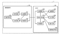
- FIG. 1 is a block diagram showing an example of a real-time management system of a paddy field in Embodiment 1 of the present invention.
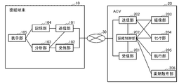
- FIG. 2 is a block diagram showing another example of the real time management system according to the first embodiment of the present invention.
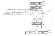
- FIG. 3 is a flowchart showing an example of the real-time management method in Embodiment 1 of the present invention.
- FIG. 4 is a block diagram showing an example of a real time management system according to Embodiment 2 of the present invention.
- FIG. 5 is a block diagram showing an example of the hardware configuration of the control terminal in the real-time management system of Embodiment 1 of the present invention.
- FIG. 6 is a block diagram showing an example of a hardware configuration of a drug dispersion air cushion boat in the real time management system according to the first embodiment of the present invention.
- Embodiment 1 The first embodiment relates to the real time management system, the chemical airborne water cushion boat, the control terminal and the real time management method of the present invention.
- FIG. 1 shows a block diagram of a real time management system in the present embodiment.
- the real-time management system 1 of the present embodiment includes a control terminal 10 and a floating air cushion boat 20 (hereinafter referred to as ACV (Air Cushion Vehicle) or hovercraft) for chemical dispersion.
- ACV Air Cushion Vehicle
- FIG. 2 the control terminal 10 and the ACV 20 can be connected via the communication network 30.
- the communication network 30 is not particularly limited, and a known computer network can be used, for example, wireless is preferable. Examples of the network include LAN (Local Area Network) and WiFi.
- LAN Local Area Network
- WiFi Wireless Fidelity
- the ACV 20 may be connected to the control terminal 10 via the communication network 30, and may be able to control the control terminal 10 and navigate the paddy field.
- the floating method of the ACV 10 is not particularly limited, and examples thereof include pressure suppression air floating, dynamic pressure air floating, pressurized air floating, and negative pressure air floating.
- the ACV 20 includes a transmitting / receiving unit (receiving unit 201, transmitting unit 202), an imaging unit 203, a sensor unit 204, a navigation unit 205, a medicine spreading unit 206, and a steering control unit 207.
- the ACV 20 has, for example, a CPU (central processing unit).
- the CPU includes, for example, a steering control unit 207.
- the receiving unit 201, the transmitting unit 202, and the steering control unit 207 may be incorporated in, for example, a data processing unit (data processing apparatus) which is hardware, or software or hardware incorporating the software. Good.
- the data processing unit may include a CPU or the like.
- Each part in ACV20 is electrically connected, for example.
- the reception unit 201 of the ACV 20 receives steering control data from the steering terminal 10.
- the steering control data is, for example, a control signal of the steering of the ACV 20.
- the steering control signal includes, for example, a control signal of the ACV 20, a control signal of the imaging unit 203, a control signal of the sensor unit 204, a control signal of the navigation unit 205, a control signal of the drug scattering unit 206, and the like.
- the control signal of the ACV 20 is, for example, a signal that controls ON-OFF of activation of the ACV 20 and the like.
- the control signal of the imaging unit 203 is, for example, a signal for controlling ON-OFF of imaging, imaging conditions, and the like.
- the control signal of the sensor unit 204 is, for example, a signal that controls ON / OFF of sensing, sensing conditions, and the like.
- the control signal of the navigation unit 205 is, for example, a signal that controls forward, reverse, turn to the left and right, stop, speed, and the like.
- the control signal of the drug spraying unit 206 is, for example, a signal for controlling start and stop of drug spraying, spraying amount and the like.
- the imaging unit 203 of the ACV 20 captures an image around the ACV 20.
- Examples of the imaging unit 203 include a camera.
- the type of the camera is not particularly limited, and for example, a high resolution camera for image analysis can be used.
- the number of imaging units 203 mounted on the ACV 20 is not particularly limited. In the real-time management system 1 of the present embodiment, it is preferable to obtain imaging data such as the growing condition of crops and the underwater condition of the paddy field, and the imaging unit 203 can pick up an imaging unit, for example, so as to It is preferable to provide 203.
- the sensor unit 204 of the ACV 20 senses environmental factors around the ACV 20.
- the type of the sensor unit 204 is not particularly limited, and can be appropriately selected depending on the type of crop in the paddy field, the season, and the like.
- Examples of the sensor unit 204 include a water level sensor, a temperature sensor, a pH sensor, a nitrogen concentration sensor, a phosphorus concentration sensor, and a urea concentration sensor.
- the type and the number of sensor units 204 mounted on the ACV 20 are not particularly limited, and may be one type, two or more types, or one or two or more types, for example.
- the navigation unit 205 of the ACV 20 causes the ACV 20 to travel.
- the navigation unit 205 includes, for example, a floating unit that floats on water by the above-described floating method, and a propulsion unit such as a propeller or a screw or a front rotor.
- the front rotor preferably has, for example, a right rotor and a left rotor, and it is preferable that the rotational speed can be controlled separately by the transmission gear.
- the ACV 20 can also be pivoted by controlling the right rotor and the left rotor separately.
- the drug spraying unit 206 of the ACV 20 sprays the drug loaded on the ACV 20.
- a dripping nozzle, a jet nozzle, and the like can be given as the drug dispersion unit 206.
- the steering control unit 207 of the ACV 20 controls the steering of each unit, for example, the imaging unit 203, the sensor unit 204, the navigation unit 205, and the medicine dispersion unit 206, based on the steering control data received by the receiving unit 201.
- the transmission unit 202 of the ACV 20 transmits the imaging data by the imaging unit 203 and the sensing data by the sensor unit 204 to the control terminal 10.
- the ACV 20 may further include, for example, a GPS (Global Positioning System).
- the ACV 20 can acquire map data around the ACV 20 via the communication network 30, for example, by GPS.
- the map data acquired by the GPS of the ACV 20 may be transmitted from the transmission unit 202 to the control terminal 10 via the communication network 30, for example.
- the map data is, for example, position coordinates of the ACV 20 on the map.
- the control terminal 10 includes a transmission unit 101, a reception unit 102, an analysis unit 103, a storage unit 104, and a display unit 105.
- the transmission unit 101, the reception unit 102, and the analysis unit 103 may be incorporated, for example, in a data processing unit (data processing apparatus) which is hardware, or may be software or hardware in which the software is incorporated.
- the data processing unit may include a central processing unit (CPU) or the like.
- CPU central processing unit
- the control terminal 10 is not particularly limited, and may be, for example, a propo, a smartphone, a tablet or the like. According to the real-time management system 1, since a smartphone or a tablet can be used as the control terminal 10, the ACV 20 can be easily steered while looking at the display content of the display unit 105, for example.
- the transmission unit 101 of the control terminal 10 transmits control control data to the ACV 20.
- the steering control data is, for example, as described above.
- the receiving unit 102 of the control terminal 10 receives, from the ACV 20, the imaging data of the imaging unit 203 and the sensing data of the sensor unit 204.
- the imaging data and the sensing data are, for example, as described above.
- the analysis unit 103 of the control terminal 10 analyzes the imaging data and the sensing data, and links the analysis data to map data of a paddy field.
- the map data of the said paddy field can be acquired by GPS of ACV20 as mentioned above, for example.
- the linking of the imaging data and the sensing data means, for example, associating the sensing data with the imaging data corresponding to each area of the paddy field in the map data of the paddy field.
- the imaging data is, for example, classified into a growth target (eg, rice seedling, rice leaf sheath etc.) and a removal target (eg, weed etc.) in the paddy field by performing image analysis by the analysis unit 103, the removal target Classification etc. can be performed whether there are many things or not.
- the storage unit 104 of the control terminal 10 stores map data of the paddy field, data received from the ACV 20 (including the imaging data and the sensing data), and analysis data analyzed by the analysis unit 103.
- the storage unit 104 may be, for example, a random access memory (RAM), a read only memory (ROM), a flash memory, a hard disk (HD), an optical disk, a floppy (registered trademark) disk (FD) or the like.
- the storage unit 104 may be built in the control terminal 10 or may be externally attached to the control terminal 10.
- the display unit 105 of the control terminal 10 links and displays the map data of the paddy field and the analysis data.
- the display unit 105 is, for example, a display.
- a map of a paddy field can be displayed and further linked with each area of the paddy field to display actual imaging data of each area and sensing data indicating the state of each area.
- FIG 5 and 6 illustrate block diagrams of hardware configurations of the control terminal 10 and the ACV 20 in the real-time management system 1, respectively.
- the control terminal 10 has, for example, a CPU (central processing unit) 11, a memory 12, a bus 13, an input device 14, a display 15, a communication device 16, a storage device 17 and the like.
- each unit is mutually connected via a bus 13 by, for example, respective interfaces (I / F).
- the CPU 11 is responsible for overall control of the control terminal 10.
- the program 18 of the present invention and other programs are executed by the CPU 11, and reading and writing of various information are performed.
- the CPU 11 functions as an analysis unit 103.
- the control terminal 10 can be connected to a communication network by, for example, the communication device 16 connected to the bus 13 and can also connect external devices such as the ACV 20 via the communication network.
- the connection method between the control terminal 10 and the external device is not particularly limited, and for example, wireless connection is preferable as described above.
- the wireless connection may be, for example, a connection using a communication network or a connection using wireless communication.
- the communication network is not particularly limited, and for example, a known communication network can be used and is the same as described above.
- the memory 12 includes, for example, a main memory, and the main memory is also referred to as a main storage device.
- the main memory is, for example, a RAM (random access memory).
- the memory 12 further includes, for example, a ROM (read only memory).
- the storage device 17 is also called, for example, a so-called auxiliary storage device with respect to the main memory (main storage device).
- the storage device 17 includes, for example, a storage medium and a drive for reading and writing to the storage medium.
- the storage medium is not particularly limited, and may be, for example, a built-in type or an external type, HD (hard disk), FD (floppy (registered trademark) disk), CD-ROM, CD-R, CD-RW, MO, Examples of the drive include a DVD, a flash memory, and a memory card, and the drive is not particularly limited.
- the storage device 17 can be exemplified by, for example, a hard disk drive (HDD) in which a storage medium and a drive are integrated, a solid state drive (SSD), and the like.
- the storage device 17 stores, for example, a program 18 such as the program of the present invention.
- the storage unit 17 is a storage unit 104, and stores, for example, map data 191 of the paddy field, received data 192 received from the ACV 20, analysis data 193 analyzed by the analysis unit 103, and the like as described above.
- the control terminal 10 has a display 15 as the display unit 105, and examples thereof include an LED display and a liquid crystal display.
- the control terminal 10 may further include, for example, an input device 14 such as a touch panel and a keyboard.
- the ACV 20 includes, for example, a CPU 21, a memory 22, a bus 23, an input device 24, a camera 25, a sensor 26, a navigation unit 205, a medicine spreading unit 206, a communication device 27, a storage device 28 and the like.
- each unit is mutually connected via a bus 23, for example, by respective interfaces (I / F).
- the CPU 21 is responsible for overall control of the ACV 20.
- the program 18 of the present invention and other programs are executed by the CPU 21, and reading and writing of various information are performed.
- the CPU 21 functions as a steering control unit 207.
- the ACV 20 can be connected to a communication network, for example, by a communication device 27 connected to the bus 23, and can be connected to the control terminal 10 via the communication network.
- the connection method between the ACV 20 and the control terminal 10 is not particularly limited, and is as described above.
- the memory 22 includes, for example, a main memory, and the main memory is also referred to as a main storage device.
- the main memory 22 reads a program 18 including an operation program such as a program of the present invention stored in an auxiliary storage device described later, and the CPU 21 receives data from the memory 22 And execute the program.
- the illustration of the main memory is, for example, the same as the illustration of the control terminal 10.
- the ACV 20 includes, for example, a camera 25 as an imaging unit 203 and various sensors 26 as a sensor unit 204.
- the navigation unit 205 and the drug dispersion unit 206 are, for example, the same as described above.
- the camera 25, the sensor 26, the navigation unit 205 and the medicine distribution unit 206 are controlled by the CPU 21 functioning as a steering control unit and 207 respectively.
- the storage device 28 is also called, for example, a so-called auxiliary storage device with respect to the main memory (main storage device).
- the illustration of the main memory is, for example, the same as the illustration of the control terminal 10.
- the storage device 28 is a storage unit, and stores, for example, imaging data 291 captured by the camera 25, sensing data 292 acquired by the sensor 26, and the like.
- the ACV 20 may further include, for example, an input device 24 and a display as a display unit.
- the input device 24 may be, for example, a touch panel or a keyboard, and the display may be, for example, an LED display or a liquid crystal display.
- FIG. 3 shows a flowchart of the method for managing paddy fields in real time according to the present embodiment.
- the real-time management method of this embodiment is implemented as follows, for example, using the real-time management system 1 of FIG. 1 and FIG.
- a steering control data transmission step (S 100), an acquired data reception step (S 104), an analysis step (S 105), a display step (S 106) Operation control data reception process (S101), imaging process (S102-1), sensing process (S102-2), navigation process (S102-3), drug dispersion process (A102) having a data storage process (S107) S102-4) includes an acquired data transmission step (S103).
- the thick frame process is the process by the control terminal 10
- the narrow frame process is the process by the ACV 20.
- each step by the control terminal 10 and each step by the ACV 20 may be sequentially performed or may be performed in parallel.
- the maneuvering terminal 10 transmits the maneuver control data to the ACV 20 (S100).
- the steering control data includes, for example, data for controlling navigation of the ACV 20, imaging with the ACV 20, sensing, and drug dispersion.
- the ACV 20 receives the maneuvering control data from the maneuvering terminal 10 (S101), and the maneuvering control unit 207 of the ACV 20 receives an imaging unit 203, a sensor unit 204, and a navigation unit 205 based on the received maneuvering control data. , And controls the operation of the drug distribution unit 206 to execute each step.
- the image capturing unit 203 of the ACV 20 captures an image of the surroundings of the ACV 20 (S102-1), and the sensor unit 204 of the ACV 20 senses environmental factors around the ACV 20 (S102-2), and the navigation unit 205 of the ACV 20 Then, the ACV 20 is made to travel (S 102-3), and the drug mounted on the ACV 20 is sprayed to the paddy field by the drug spraying unit 206 of the ACV 20 (S 102-4).
- the ACV 20 transmits acquisition data (the imaging data and the sensing data) to the control terminal 10 (S103), and the control terminal 10 receives the acquisition data (the imaging data and the sensing data) from the ACV 20. It receives (S104).
- the acquired data (the imaging data and the sensing data) is analyzed by the analysis unit 103 of the control terminal 10, and the analysis data is linked to the map data of the paddy field (S105).
- the map data of the paddy field may be stored in the control terminal 10 in advance, for example.
- the linking of the analysis data to map data of a paddy field can also be carried out by GPS mapping, for example, by mounting a GPS on the ACV 20.
- map data of the paddy field, the data received from the ACV 20, and the analysis data analyzed by the analysis unit 103 are stored (S107).
- the map data of the paddy field and the analysis data are linked and displayed by the display unit 105 of the control terminal 10 (S106).
- the display unit 105 displays the actual imaging data of each area of the paddy field and the sensing data indicating the state of each area in association with the map data of the paddy field, thereby enabling the operator Can grasp the condition of paddy field in real time. For this reason, the pilot can determine, for example, whether or not the drug needs to be sprayed, the amount of spraying, etc., for each region of the paddy field, based on the real-time information while viewing the display on the display unit 105.
- the pilot can further determine the navigation direction, navigation speed, and the like of the ACV 20 based on the display content of the display unit 105 of the steering terminal 10, for example, an image around the ACV 20. .
- the ACV 20 is made to travel in a direction to bypass the obstacle, or when there is a weed in the periphery in the image, drug treatment
- the navigation speed of the ACV 20 is reduced.
- the determined navigation conditions are transmitted as maneuvering control data from the maneuvering terminal 10 to the ACV 20 (S100).
- the ACV 20 receives the maneuver control data (S101), and navigates based on the maneuver control data (S102-03).
- the pilot can similarly determine the presence or absence of the drug dispersion from the ACV 20, the drug dispersion amount, and the like based on the display contents of the display unit 105 of the control terminal 10, for example, the image around the ACV 20. Specifically, for example, when there is no weed in the periphery of the image, the drug dispersion is turned off, and when there is a weed in the periphery in the image, the drug dispersion is turned on according to the amount of weeds , Changing the amount of drug sprayed, etc. Then, the control terminal 10 transmits the determined spraying condition as steering control data to the ACV 20 (S100). On the other hand, the ACV 20 receives the steering control data (S101), and disperses the medicine based on the steering control data (S102-4).
- the pilot senses various data while navigating the ACV 20 (S102-2).
- This sensing data is real-time information indicating the condition of the paddy field. Therefore, analysis is performed and linked to map data of the paddy field (S105), and by displaying the analysis result together with the image (S106), for example, the state of the paddy field can be managed in real time.
- the present invention it is possible to acquire imaging data of each area of the paddy field and sensing data indicating the state of each area while traveling ACV in the paddy field. And since the pilot can grasp the state of the paddy field in real time by linking the imaging data and the sensing data with the map data of the paddy field, it becomes possible to disperse the medicine appropriately.
- the agent is not sprayed, and the agent is dispersed only when the object to be removed is identified. It is possible to make pinpoint drug dispersion as described above. Further, based on the imaging data, it is possible to adjust the amount of drug to be dispersed according to the amount of the removal target. Also, for example, when a growth target (for example, rice seedling, rice leaf sheath etc.) is confirmed in the imaging data, navigation of the ACV is performed based on the imaging data so as not to touch the growth target. It is also possible to adjust. Also, since the ACV is used instead of a flight drone, unnecessary diffusion of the drug in the air can be prevented.
- a growth target for example, rice seedling, rice leaf sheath etc.
- the state of the paddy field can be grasped
- the state of the paddy field can be grasped
- the second embodiment exemplifies the more specific implementation functions and the relation of processes for the terminal 10 and the ACV 20 in the first embodiment.
- Table 1 below illustrates the functions of the terminal 10 and the functions of the ACV 20.
- the program of the present embodiment is a program that can execute the above-described real-time management method on a computer.
- the program of the present embodiment may be recorded on, for example, a computer readable recording medium.
- the recording medium is not particularly limited, and examples thereof include random access memory (RAM), read only memory (ROM), hard disk (HD), optical disk, floppy (registered trademark) disk (FD) and the like.
- the air cushion boat and the control terminal can be connected via a communication network;
- the air cushion boat is A transmission / reception unit, an imaging unit, a sensor unit, a navigation unit, a medicine dispersion unit, and a steering control unit;
- the imaging unit images the periphery of the air cushion boat,
- the sensor unit senses environmental factors around the air cushion boat,
- the navigation unit causes the air cushion boat to travel.
- the drug spraying unit sprays the drug mounted on the air cushion
- the transmission / reception unit receives maneuvering control data from the maneuvering terminal, and transmits imaging data by the imaging unit and sensing data by the sensor unit to the maneuvering terminal.
- the steering control unit controls the steering of each part based on the steering control data;
- the control terminal is A transmission / reception unit, an analysis unit, a storage unit, and a display unit;
- the transmission / reception unit receives the imaging data and the sensing data from the air cushion boat, and transmits steering control data to the air cushion boat.
- the analysis unit analyzes the imaging data and the sensing data, and associates the analysis data with map data of a paddy field.
- the storage unit stores map data of the paddy field, received data received from the air cushion boat, and analysis data analyzed by the analysis unit.
- the real time management system of a paddy field wherein the display unit links and displays the map data of the paddy field and the analysis data.
- the paddy field real-time management system according to appendix 1, wherein the imaging unit is a high resolution camera for image analysis.
- the imaging unit is a high resolution camera for image analysis.
- the sensor unit is at least one selected from the group consisting of a water level sensor, a temperature sensor, a pH sensor, a nitrogen concentration sensor, a phosphorus concentration sensor, and a urea concentration sensor system.
- the control terminal is a smartphone or a tablet.
- the imaging unit images the periphery of the air cushion boat,
- the sensor unit senses environmental factors around the air cushion boat,
- the navigation unit causes the air cushion boat to travel.
- the drug spraying unit sprays the drug mounted on the air cushion.
- the transmission / reception unit receives maneuvering control data from the maneuvering terminal, and transmits imaging data by the imaging unit and sensing data by the sensor unit to the maneuvering terminal.
- the steering control unit controls the steering of each part based on the steering control data,
- a drug-dispersion floating air cushion boat characterized in that it is connectable to the control terminal via a communication network.
- [Supplementary Note 6] The waterborne air cushion boat according to appendix 5, wherein the imaging unit is a high resolution camera for image analysis.
- the sensor unit is at least one selected from the group consisting of a water level sensor, a temperature sensor, a pH sensor, a nitrogen concentration sensor, a phosphorus concentration sensor, and a urea concentration sensor. Air cushion boat.
- the analysis unit analyzes the imaging data and the sensing data, and associates the analysis data with map data of a paddy field.
- the storage unit stores map data of a paddy field, received data received from the air cushion boat, and analysis data analyzed by the analysis unit.
- the display unit links and displays the map data and the analysis data.
- a control terminal for a pharmaceutical airborne water cushion boat which is connectable to the air cushion boat via a communication network.
- the present invention it is possible to acquire information on the paddy field while, for example, traveling an air cushion boat on a paddy field for drug dispersion, so that the paddy field can be managed in real time. Then, based on the information of the paddy field in real time, for example, it is possible to determine whether or not the drug needs to be sprayed, and the area where the drug needs to be sprayed. For this reason, management of a paddy field and control of a chemical
- Control terminal 20 Waterborne air cushion boat 101 for drug dispersion Waterborne unit 102 Transmitter 102 Receiver 103 Analysis unit 104 Storage unit 105 Display unit 201 Receiver 202 Transmitter 203 Imager 204 Sensor unit 205 Navigation unit 206 Drug dispersion unit 207 Steering control unit
Landscapes
- Engineering & Computer Science (AREA)
- Life Sciences & Earth Sciences (AREA)
- Combustion & Propulsion (AREA)
- Mechanical Engineering (AREA)
- Ocean & Marine Engineering (AREA)
- Chemical & Material Sciences (AREA)
- Pest Control & Pesticides (AREA)
- Insects & Arthropods (AREA)
- Computer Networks & Wireless Communication (AREA)
- Wood Science & Technology (AREA)
- Zoology (AREA)
- Environmental Sciences (AREA)
- Selective Calling Equipment (AREA)
- Catching Or Destruction (AREA)
- Management, Administration, Business Operations System, And Electronic Commerce (AREA)
- Guiding Agricultural Machines (AREA)
Abstract
ドローンではなく遠隔操作の無人機により水田をリアルタイムに管理し、必要に応じた薬剤散布を行う新たなシステムを提供する。リアルタイム管理システム1は、薬剤散布用水上エアクッション艇20と操縦端末10とを含む。エアクッション艇20は、その周囲を撮像する撮像部203、前記周囲の環境要因をセンシングするセンサ部204、航行部205、薬剤散布部206、操縦端末10から操縦制御データを受信する受信部201、操縦端末10へ撮像データとセンシングデータとを送信する送信部202、操縦制御データに基づき制御する操縦制御部207を有する。操縦端末10は、エアクッション艇20から撮像データとセンシングデータとを受信する受信部102、エアクッション艇20へ操縦制御データを送信する送信部101、撮像データおよびセンシングデータを分析して水田マップデータに紐づけする分析部103、マップデータと受信データと分析データとを記憶する記憶部104、マップデータと分析データとを紐づけて表示する表示部105を有する。
Description
本発明は、水田のリアルタイム管理システム、薬剤散布用水上エアクッション艇、操縦端末、リアルタイム管理方法、プログラム、および記録媒体に関する。
水田への薬剤散布において、遠隔操作が可能なドローンが利用されている。しかしながら、日本のように、1つ1つの農地面積が狭い国の場合、ドローンからの空中散布では、薬剤が風で流れてしまい、隣接する農地にまで薬剤が散布されてしまうというリスクがある。例えば、健康志向が広まる昨今、農家によっては、使用する薬剤の種類の選択、使用量の制限等を徹底することで、農作物の商品価値を高めることを重要視するという契約農家もある。しかし、前述のように、薬剤が流れてしまうと、自らの農地については管理ができていても、近隣の薬剤散布による影響をうける可能性がある。
また、薬剤は、必ずしも水田の全体に散布する必要はなく、ピンポイントの散布で足りる場合もある。しかし、航空飛行するドローンにより、水田において上空から薬剤散布が必要な箇所を見つけ出し、ピンポイントで散布することは、非常に困難である。
また、コントローラで操縦する薬剤散布用ボートも報告されているが、操縦者が視認できる範囲で操縦できるにとどまり、必要な箇所にピンポイントで散布することは、同様に困難である(特許文献1)。
そこで、本発明は、空中飛行のドローンではなく、遠隔操作で操縦する無人機を用いて、水田をリアルタイムに管理し、必要に応じた薬剤散布を可能とする新たなシステムの提供を目的とする。
前記目的を達成するために、本発明のシステムは、水田のリアルタイム管理システムであり、
薬剤散布用水上エアクッション艇と、前記エアクッション艇を操縦する操縦端末とを含み、
前記エアクッション艇と前記操縦端末とは、通信回線網を介して接続可能であり;
前記エアクッション艇は、
送受信部、撮像部、センサ部、航行部、薬剤散布部、および操縦制御部を有し、
前記撮像部は、前記エアクッション艇の周囲を撮像し、
前記センサ部は、前記エアクッション艇の周囲の環境要因をセンシングし、
前記航行部は、前記エアクッション艇を航行させ、
前記薬剤散布部は、前記エアクッションに搭載された薬剤を散布し、
前記送受信部は、前記操縦端末から、操縦制御データを受信し、前記操縦端末へ、前記撮像部による撮像データ、および前記センサ部によるセンシングデータを送信し、
前記操縦制御部は、前記操縦制御データに基づいて、各部の操縦を制御し;
前記操縦端末は、
送受信、分析部、記憶部、および表示部を有し、
前記送受信部は、前記エアクッション艇から、前記撮像データ、および前記センシングデータを受信し、前記エアクッション艇へ、操縦制御データを送信し、
前記分析部は、前記撮像データおよび前記センシングデータを分析して、水田のマップデータに紐づけし、
前記記憶部は、前記水田のマップデータ、前記エアクッション艇から受信した受信データ、および前記分析部により分析した分析データを、記憶し、
前記表示部は、前記水田のマップデータと前記分析データとを紐づけて表示する
ことを特徴とする。
薬剤散布用水上エアクッション艇と、前記エアクッション艇を操縦する操縦端末とを含み、
前記エアクッション艇と前記操縦端末とは、通信回線網を介して接続可能であり;
前記エアクッション艇は、
送受信部、撮像部、センサ部、航行部、薬剤散布部、および操縦制御部を有し、
前記撮像部は、前記エアクッション艇の周囲を撮像し、
前記センサ部は、前記エアクッション艇の周囲の環境要因をセンシングし、
前記航行部は、前記エアクッション艇を航行させ、
前記薬剤散布部は、前記エアクッションに搭載された薬剤を散布し、
前記送受信部は、前記操縦端末から、操縦制御データを受信し、前記操縦端末へ、前記撮像部による撮像データ、および前記センサ部によるセンシングデータを送信し、
前記操縦制御部は、前記操縦制御データに基づいて、各部の操縦を制御し;
前記操縦端末は、
送受信、分析部、記憶部、および表示部を有し、
前記送受信部は、前記エアクッション艇から、前記撮像データ、および前記センシングデータを受信し、前記エアクッション艇へ、操縦制御データを送信し、
前記分析部は、前記撮像データおよび前記センシングデータを分析して、水田のマップデータに紐づけし、
前記記憶部は、前記水田のマップデータ、前記エアクッション艇から受信した受信データ、および前記分析部により分析した分析データを、記憶し、
前記表示部は、前記水田のマップデータと前記分析データとを紐づけて表示する
ことを特徴とする。
本発明の薬剤散布用水上エアクッション艇は、
送受信部、撮像部、センサ部、航行部、薬剤散布部、および操縦制御部を有し、
前記撮像部は、前記エアクッション艇の周囲を撮像し、
前記センサ部は、前記エアクッション艇の周囲の環境要因をセンシングし、
前記航行部は、前記エアクッション艇を航行させ、
前記薬剤散布部は、前記エアクッションに搭載された薬剤を散布し、
前記送受信部は、操縦端末から、操縦制御データを受信し、前記操縦端末へ、前記撮像部による撮像データ、および前記センサ部によるセンシングデータを送信し、
前記操縦制御部は、前記操縦制御データに基づいて、各部の操縦を制御し、
前記操縦端末と、通信回線網を介して接続可能であることを特徴とする。
送受信部、撮像部、センサ部、航行部、薬剤散布部、および操縦制御部を有し、
前記撮像部は、前記エアクッション艇の周囲を撮像し、
前記センサ部は、前記エアクッション艇の周囲の環境要因をセンシングし、
前記航行部は、前記エアクッション艇を航行させ、
前記薬剤散布部は、前記エアクッションに搭載された薬剤を散布し、
前記送受信部は、操縦端末から、操縦制御データを受信し、前記操縦端末へ、前記撮像部による撮像データ、および前記センサ部によるセンシングデータを送信し、
前記操縦制御部は、前記操縦制御データに基づいて、各部の操縦を制御し、
前記操縦端末と、通信回線網を介して接続可能であることを特徴とする。
本発明の操縦端末は、薬剤散布用水上エアクッション艇用の操縦端末であり、
送受信部、分析部、記憶部、および表示部を有し、
前記受信部は、前記エアクッション艇から、撮像データ、およびセンシングデータを受信し、前記エアクッション艇へ、操縦制御データを送信し、
前記分析部は、前記撮像データおよび前記センシングデータを分析して、水田のマップデータに紐づけし、
前記記憶部は、水田のマップデータ、前記エアクッション艇から受信した受信データ、および前記分析部により分析した分析データを記憶し、
前記表示部は、前記マップデータと前記分析データとを紐づけて表示し、
前記エアクッション艇と、通信回線網を介して接続可能であることを特徴とする。
送受信部、分析部、記憶部、および表示部を有し、
前記受信部は、前記エアクッション艇から、撮像データ、およびセンシングデータを受信し、前記エアクッション艇へ、操縦制御データを送信し、
前記分析部は、前記撮像データおよび前記センシングデータを分析して、水田のマップデータに紐づけし、
前記記憶部は、水田のマップデータ、前記エアクッション艇から受信した受信データ、および前記分析部により分析した分析データを記憶し、
前記表示部は、前記マップデータと前記分析データとを紐づけて表示し、
前記エアクッション艇と、通信回線網を介して接続可能であることを特徴とする。
本発明の方法は、水田のリアルタイム管理方法であり、
前記本発明の薬剤散布用水上エアクッション艇と、前記本発明の操縦端末を使用し、
前記エアクッション艇と前記操縦端末とを、通信回線網を介して接続し;
前記操縦端末の送受信部により、前記エアクッション艇へ、操縦制御データを送信する送信工程、
前記エアクッション艇の送受信部により、前記操縦端末からの前記操縦制御データを受信する受信工程、
前記エアクッション艇の前記撮像部により、前記エアクッション艇の周囲を撮像する撮像工程、
前記エアクッション艇の前記センサ部により、前記エアクッション艇の周囲の環境要因をセンシングするセンシング工程、
前記エアクッション艇の航行部により、前記エアクッション艇を航行させる航行工程、
前記エアクッション艇の薬剤散布部により、前記エアクッション艇に搭載された薬剤を散布する工程、
前記エアクッション艇の送受信部により、前記操縦端末からの操縦制御データを受信する工程、
前記エアクッション艇の操縦制御部により、前記操縦制御データに基づいて、各部の操縦を制御する工程、
前記エアクッションの送受信部により、前記操縦端末へ、前記撮像部による撮像データ、および前記センサ部によるセンシングデータを送信する工程、
前記操縦端末の送受信部により、前記エアクッションからの前記撮像データ、および前記センシングデータを受信する工程、
前記操縦端末の分析部により、前記撮像データおよび前記センシングデータを分析して、水田のマップデータに紐づけする工程、
前記操縦端末の前記記憶部により、前記水田のマップデータ、前記エアクッション艇から受信したデータ、および前記分析部により分析した分析データを、記憶する工程、
前記操縦端末の表示部により、前記水田のマップデータと前記分析データとを紐づけて表示する工程を含むことを特徴とする。
前記本発明の薬剤散布用水上エアクッション艇と、前記本発明の操縦端末を使用し、
前記エアクッション艇と前記操縦端末とを、通信回線網を介して接続し;
前記操縦端末の送受信部により、前記エアクッション艇へ、操縦制御データを送信する送信工程、
前記エアクッション艇の送受信部により、前記操縦端末からの前記操縦制御データを受信する受信工程、
前記エアクッション艇の前記撮像部により、前記エアクッション艇の周囲を撮像する撮像工程、
前記エアクッション艇の前記センサ部により、前記エアクッション艇の周囲の環境要因をセンシングするセンシング工程、
前記エアクッション艇の航行部により、前記エアクッション艇を航行させる航行工程、
前記エアクッション艇の薬剤散布部により、前記エアクッション艇に搭載された薬剤を散布する工程、
前記エアクッション艇の送受信部により、前記操縦端末からの操縦制御データを受信する工程、
前記エアクッション艇の操縦制御部により、前記操縦制御データに基づいて、各部の操縦を制御する工程、
前記エアクッションの送受信部により、前記操縦端末へ、前記撮像部による撮像データ、および前記センサ部によるセンシングデータを送信する工程、
前記操縦端末の送受信部により、前記エアクッションからの前記撮像データ、および前記センシングデータを受信する工程、
前記操縦端末の分析部により、前記撮像データおよび前記センシングデータを分析して、水田のマップデータに紐づけする工程、
前記操縦端末の前記記憶部により、前記水田のマップデータ、前記エアクッション艇から受信したデータ、および前記分析部により分析した分析データを、記憶する工程、
前記操縦端末の表示部により、前記水田のマップデータと前記分析データとを紐づけて表示する工程を含むことを特徴とする。
本発明のプログラムは、前記本発明の水田のリアルタイム管理方法をコンピュータ上で実行可能なことを特徴とする。
本発明のコンピュータ読み取り可能な記録媒体は、前記本発明のプログラムを記録していることを特徴とする。
本発明によれば、例えば、水田において薬剤散布用水上エアクッション艇を航行させながら、水田の情報を取得できるため、リアルタイムでも水田の管理を行うことができる。そして、リアルタイムでの水田の情報に基づいて、例えば、薬剤の散布の要否、薬剤散布が必要な領域の判断等も行える。このため、簡便に、水田の管理と薬剤散布の調節等も可能となる。
本発明の実施形態について、図を用いて説明する。本発明は、下記の実施形態によって何ら限定および制限されない。以下の各図において、同一部分には、同一符号を付している。各実施形態の説明は、特に言及がない限り、互いの説明を援用できる。さらに、各実施形態の構成は、特に言及がない限り、組合せ可能である。
[実施形態1]
実施形態1は、本発明のリアルタイム管理システム、薬剤散布用水上エアクッション艇、操縦端末およびリアルタイム管理方法に関する。
実施形態1は、本発明のリアルタイム管理システム、薬剤散布用水上エアクッション艇、操縦端末およびリアルタイム管理方法に関する。
図1に、本実施形態におけるリアルタイム管理システムのブロック図を示す。図1に示すように、本実施形態のリアルタイム管理システム1は、操縦端末10と、薬剤散布用水上エアクッション艇20(以下、ACV(Air cushion vehicle)またはホバークラフトという)とを含む。そして、図2に示すように、操縦端末10とACV20とが、通信回線網30を介して接続可能である。
通信回線網30は、特に制限されず、公知のコンピュータネットワークを使用でき、例えば、無線が好ましい。前記ネットワークは、例えば、LAN(Local Area Network)、WiFi等があげられる
ACV20は、通信回線網30を介して、操縦端末10と接続され、操縦端末10により操縦でき、水田を航行できればよい。ACV10の浮上方式は、特に制限されず、例えば、制圧式空気浮上、動圧式空気浮上、加圧式空気浮上、負圧式空気浮上等があげられる。
ACV20は、送受信部(受信部201、送信部202)、撮像部203、センサ部204、航行部205、薬剤散布部206、操縦制御部207を有する。ACV20は、例えば、CPU(中央演算装置)を有する。前記CPUは、例えば、操縦制御部207を含む。ACV20において、受信部201、送信部202、および操縦制御部207は、例えば、ハードウェアであるデータ処理部(データ処理装置)に組み込まれてもよく、ソフトウェアまたは前記ソフトウェアが組み込まれたハードウェアでもよい。前記データ処理部は、CPU等を備えてもよい。ACV20における各部は、例えば、電気的に接続されている。
ACV20の受信部201は、操縦端末10から、操縦制御データを受信する。前記操縦制御データは、例えば、ACV20の操縦の制御シグナルである。前記操縦制御シグナルは、例えば、ACV20の制御シグナル、撮像部203の制御シグナル、センサ部204の制御シグナル、航行部205の制御シグナル、薬剤散布部206の制御シグナル等を含む。ACV20の制御シグナルは、例えば、ACV20の起動のON-OFF等を制御するシグナルである。撮像部203の制御シグナルは、例えば、撮像のON-OFF、撮像条件等を制御するシグナルである。センサ部204の制御シグナルは、例えば、センシングのON-OFF、センシング条件等を制御するシグナルである。航行部205の制御シグナルは、例えば、前進、後進、左右への方向転換、停止、スピード等を制御するシグナルである。薬剤散布部206の制御シグナルは、例えば、薬剤散布の開始と停止、散布量等を制御するシグナルである。
ACV20の撮像部203は、ACV20の周囲を撮像する。撮像部203としては、例えば、カメラがあげられる。前記カメラの種類は、特に制限されず、例えば、画像解析用途の高解像度カメラ等が使用できる。ACV20に搭載する撮像部203の数は、特に制限されない。本実施形態のリアルタイム管理システム1では、作物の生育状況、水田の水中状況等の撮像データを得ることが好ましく、撮像部203は、例えば、水田における表面、水中等を撮像できるように、撮像部203を備えることが好ましい。
ACV20のセンサ部204は、ACV20の周囲の環境要因をセンシングする。センサ部204の種類は、特に制限されず、水田の作物の種類、季節等に応じて、適宜選択できる。センサ部204としては、例えば、水位センサ、温度センサ、pHセンサ、窒素濃度センサ、リン濃度センサ、および尿素濃度センサ等があげられる。ACV20に搭載するセンサ部204の種類と数は、特に制限されず、例えば、1種類でもよいし2種類以上でもよく、また、1つでもよいし2つ以上でもよい。
ACV20の航行部205は、ACV20を航行させる。航行部205は、例えば、前述した浮上方式により水上に浮上させる浮上部、プロペラまたはスクリューまたはフロントロータ等の推進部等を含む。前記フロントロータは、例えば、右ロータと左ロータを有し、それぞれ別個に、変速ギアにより回転数を制御できることが好ましい。このように、前記右ロータと前記左ロータとを、それぞれ別個に制御することで、ACV20を旋回することもできる。
ACV20の薬剤散布部206は、ACV20に搭載された薬剤を散布する。薬剤散布部206は、例えば、滴下ノズル、噴射ノズル等があげられる。
ACV20の操縦制御部207は、受信部201が受信した前記操縦制御データに基づいて、各部、例えば、撮像部203、センサ部204、航行部205、薬剤散布部206の操縦を制御する。
ACV20の送信部202は、操縦端末10へ、撮像部203による撮像データ、およびセンサ部204によるセンシングデータを送信する。
ACV20は、例えば、さらにGPS(Global Positioning System)を備えてもよい。ACV20は、例えば、GPSにより、ACV20周辺のマップデータを、通信回線網30を介して取得することができる。ACV20のGPSにより取得したマップデータは、例えば、通信回線網30を介して、送信部202から操縦端末10に送信してもよい。前記マップデータは、例えば、地図におけるACV20の位置座標である。
操縦端末10は、送信部101、受信部102、分析部103、記憶部104、および表示部105を有する。送信部101、受信部102、分析部103は、例えば、ハードウェアであるデータ処理部(データ処理装置)に組み込まれてもよく、ソフトウェアまたは前記ソフトウェアが組み込まれたハードウェアでもよい。前記データ処理部は、中央演算装置(CPU)等を備えてもよい。操縦端末10の各部は、例えば、電気的に接続されている。
操縦端末10は、特に制限されず、例えば、プロポ、スマートフォン、タブレット等があげられる。リアルタイム管理システム1によれば、操縦端末10としてスマートフォンまたはタブレット等を使用できるため、例えば、表示部105の表示内容を見ながら、容易にACV20を操縦できる。
操縦端末10の送信部101は、ACV20へ、操縦制御データを送信する。前記操縦制御データは、例えば、前述の通りである。
操縦端末10の受信部102は、ACV20から、撮像部203の前記撮像データ、およびセンサ部204の前記センシングデータを受信する。前記撮像データおよび前記センシングデータは、例えば、前述の通りである。
操縦端末10の分析部103は、前記撮像データおよび前記センシングデータを分析して、水田のマップデータに紐づけする。前記水田のマップデータは、例えば、前述のように、ACV20のGPSにより取得することができる。前記撮像データおよび前記センシングデータの紐づけとは、例えば、前記水田のマップデータに、水田の各領域に該当する前記撮像データと前記センシングデータを関連づけることを意味する。前記撮像データは、例えば、分析部103により画像解析を行うことによって、水田における生育対象物(例えば、稲苗、稲葉鞘等)と除去対象物(例えば、雑草等)との分類、前記除去対象物が多い箇所か否かの分類等を行うことができる。
操縦端末10の記憶部104は、前記水田のマップデータ、ACV20から受信したデータ(前記撮像データおよび前記センシングデータを含む)、および分析部103により分析した分析データを記憶する。記憶部104は、例えば、ランダムアクセスメモリ(RAM)、読み出し専用メモリ(ROM)、フラッシュメモリー、ハードディスク(HD)、光ディスク、フロッピー(登録商標)ディスク(FD)等があげられる。記憶部104は、例えば、操縦端末10に内蔵されてもいし、操縦端末10に外付けされてもよい。
操縦端末10の表示部105は、前記水田のマップデータと前記分析データとを紐づけて表示する。表示部105は、例えば、ディスプレイである。表示部105において、例えば、水田のマップを表示し、さらに、水田の各領域と紐づけして、前記各領域の実際の撮像データと前記各領域の状態を示すセンシングデータを表示できる。
また、図5および図6に、リアルタイム管理システム1における操縦端末10およびACV20のハードウェア構成のブロック図を、それぞれ例示する。
図5に示すように、操縦端末10は、例えば、CPU(中央処理装置)11、メモリ12、バス13、入力装置14、ディスプレイ15、通信デバイス16、記憶装置17等を有する。前記ハードウェア構成において各部は、例えば、それぞれのインターフェイス(I/F)により、バス13を介して、相互に接続されている。
CPU11は、操縦端末10の全体の制御を担う。操縦端末10において、CPU11により、例えば、本発明のプログラム18やその他のプログラムが実行され、また、各種情報の読み込みや書き込みが行われる。具体的に、操縦端末10は、例えば、CPU11が、分析部103として機能する。
操縦端末10は、例えば、バス13に接続された通信デバイス16により、通信回線網に接続でき、前記通信回線網を介して、ACV20等の外部機器も接続できる。操縦端末10と前記外部機器との接続方式は、特に制限されず、例えば、前述のように無線による接続が好ましい。前記無線による接続は、例えば、通信回線網を利用した接続でもよいし、無線通信を利用した接続でもよい。前記通信回線網は、特に制限されず、例えば、公知の通信回線網を使用でき、前述と同様である。
メモリ12は、例えば、メインメモリを含み、前記メインメモリは、主記憶装置ともいう。CPU11が処理を行う際には、例えば、後述する補助記憶装置に記憶されている、本発明のプログラム等の動作プログラムを含むプログラム18を、メモリ12が読み込み、CPU11は、メモリ12からデータを受け取って、前記プログラムを実行する。前記メインメモリは、例えば、RAM(ランダムアクセスメモリ)である。メモリ12は、例えば、さらに、ROM(読み出し専用メモリ)を含む。
記憶装置17は、例えば、前記メインメモリ(主記憶装置)に対して、いわゆる補助記憶装置ともいう。記憶装置17は、例えば、記憶媒体と、前記記憶媒体に読み書きするドライブとを含む。前記記憶媒体は、特に制限されず、例えば、内蔵型でも外付け型でもよく、HD(ハードディスク)、FD(フロッピー(登録商標)ディスク)、CD-ROM、CD-R、CD-RW、MO、DVD、フラッシュメモリー、メモリーカード等があげられ、前記ドライブは、特に制限されない。記憶装置17は、例えば、記憶媒体とドライブとが一体化されたハードディスクドライブ(HDD)、ソリッドステートドライブ(SSD)等も例示できる。記憶装置17は、例えば、本発明のプログラム等のプログラム18が格納される。記憶装置17は、記憶部104であり、例えば、前述のような、前記水田のマップデータ191、ACV20から受信した受信データ192、分析部103で分析した分析データ193等が格納される。
操縦端末10は、表示部105として、ディスプレイ15を有し、例えば、LEDディスプレイ、液晶ディスプレイ等があげられる。操縦端末10は、例えば、さらに、入力装置14を有してもよく、例えば、タッチパネル、キーボード等があげられる。
図6に示すように、ACV20は、例えば、CPU21、メモリ22、バス23、入力装置24、カメラ25、センサ26、航行部205、薬剤散布部206、通信デバイス27、記憶装置28等を有する。前記ハードウェア構成において各部は、例えば、それぞれのインターフェイス(I/F)により、バス23を介して、相互に接続されている。
CPU21は、ACV20の全体の制御を担う。ACV20において、CPU21により、例えば、本発明のプログラム18やその他のプログラムが実行され、また、各種情報の読み込みや書き込みが行われる。具体的に、ACV20は、例えば、CPU21が、操縦制御部207として機能する。
ACV20は、例えば、バス23に接続された通信デバイス27により、通信回線網に接続でき、前記通信回線網を介して、操縦端末10と接続できる。ACV20と操縦端末10との接続方式は、特に制限されず、前述の通りである。
メモリ22は、例えば、メインメモリを含み、前記メインメモリは、主記憶装置ともいう。CPU21が処理を行う際には、例えば、後述する補助記憶装置に記憶されている、本発明のプログラム等の動作プログラムを含むプログラム18を、メモリ22が読み込み、CPU21は、メモリ22からデータを受け取って、前記プログラムを実行する。前記メインメモリの例示は、例えば、操縦端末10における例示と同様である。
ACV20は、例えば、撮像部203としてカメラ25を有し、センサ部204として各種センサ26を有する。航行部205および薬剤散布部206は、例えば、前述と同様である。カメラ25、センサ26、航行部205および薬剤散布部206は、CPU21が操縦制御部と207として機能することにより、それぞれ制御される。
記憶装置28は、例えば、前記メインメモリ(主記憶装置)に対して、いわゆる補助記憶装置ともいう。前記メインメモリの例示は、例えば、操縦端末10における例示と同様である。記憶装置28は、記憶部であり、例えば、カメラ25で撮像した撮像データ291、センサ26で取得したセンシングデータ292等が格納される。
ACV20は、例えば、さらに、入力装置24、表示部としてディスプレイ等を有してもよい。入力装置24は、例えば、タッチパネル、キーボード等があげられ、前記ディスプレイは、例えば、LEDディスプレイ、液晶ディスプレイ等があげられる。
つぎに、図3に、本実施形態における水田のリアルタイム管理方法のフローチャートを示す。本実施形態のリアルタイム管理方法は、例えば、図1および図2のリアルタイム管理システム1を用いて、つぎのように実施する。
図3に示すように、本実施形態のリアルタイム管理方法は、操縦端末10による、操縦制御データ送信工程(S100)、取得データ受信工程(S104)、分析工程(S105)、表示工程(S106)およびデータ記憶工程(S107)を有し、ACV20による、操縦制御データ受信工程(S101)、撮像工程(S102-1)、センシング工程(S102-2)、航行工程(S102-3)、薬剤散布工程(S102-4)、取得データ送信工程(S103)を含む。図3において、太枠の工程は、操縦端末10による工程であり、細枠の工程は、ACV20による工程である。本実施形態において、操縦端末10による各工程と、ACV20による各工程は、それぞれ、順次行われてもよいし、並行して行われてもよい。
まず、操縦端末10が、ACV20に、前記操縦制御データを送信する(S100)。前記操縦制御データには、例えば、ACV20の航行、ACV20による撮像、センシング、および薬剤散布を制御するデータが含まれる。
そして、ACV20は、操縦端末10から、前記操縦制御データを受信(S101)し、受信した前記操縦制御データに基づいて、ACV20の操縦制御部207は、撮像部203、センサ部204、航行部205、および薬剤散布部206の操縦を制御して、各工程を実行する。
すなわち、ACV20の撮像部203により、ACV20の周囲を撮像し(S102-1)し、ACV20のセンサ部204により、ACV20の周囲の環境要因をセンシングし(S102-2)、ACV20の航行部205により、ACV20を航行させ(S102-3)、ACV20の薬剤散布部206により、ACV20に搭載した薬剤を、水田に散布する(S102-4)。
つぎに、ACV20は、操縦端末10に、取得データ(前記撮像データおよび前記センシングデータ)を送信し(S103)、操縦端末10は、ACV20から、前記取得データ(前記撮像データおよび前記センシングデータ)を受信する(S104)。
そして、操縦端末10の分析部103により、前記取得データ(前記撮像データおよび前記センシングデータ)を分析して、分析データを、水田のマップデータに紐づけする(S105)。前記水田のマップデータは、例えば、予め、操縦端末10に記憶させてもよい。水田のマップデータへの前記分析データの紐づけは、例えば、ACV20にGPSを搭載し、GPSマッピングにより行うこともできる。
そして、前記水田のマップデータ、ACV20から受信したデータ、および分析部103により分析した分析データを記憶する(S107)。
また、操縦端末10の表示部105により、前記水田のマップデータと前記分析データとを紐づけて表示する(S106)。このように、表示部105に、前記水田のマップデータと紐づけて、前記水田の各領域の実際の撮像データと、前記各領域の状態を示すセンシングデータとが表示されることで、操縦者は、リアルタイムで水田の状態を把握できる。このため、操縦者は、表示部105の表示を見ながら、リアルタイムの情報に基づいて、水田の各領域について、例えば、薬剤の散布の要否、散布量等を決定できる。
具体的に、本実施形態によれば、操縦者は、操縦端末10の表示部105の表示内容、例えば、ACV20の周囲の画像に基づいて、さらに、ACV20の航行方向、航行スピード等を決定できる。具体的には、例えば、前記画像において進行方向に障害物がある場合は、前記障害物を迂回するような方向にACV20を航行させたり、前記画像において周囲に雑草がある場合は、薬剤処理を効果的に行うために、ACV20の航行スピードを減速する等である。そして、決定した航行条件を操縦制御データとして、操縦端末10からACV20に、送信する(S100)。他方、ACV20は、前記操縦制御データを受信し(S101)、前記操縦制御データに基づいて、航行する(S102-03)。
また、操縦者は、同様に、操縦端末10の表示部105の表示内容、例えば、ACV20の周囲の画像に基づいて、さらに、ACV20からの薬剤散布の有無、薬剤散布量等を決定できる。具体的には、例えば、前記画像において周囲に雑草がない場合は、薬剤散布をOFFにする、前記画像において周囲に雑草がある場合は、薬剤散布をONにする、前記雑草の量に応じて、薬剤散布量を変化させる等である。そして、決定した散布条件を操縦制御データとして、操縦端末10からACV20に、送信する(S100)。他方、ACV20は、前記操縦制御データを受信し(S101)、前記操縦制御データに基づいて、薬剤散布する(S102-4)。
また、操縦者は、ACV20を航行させながら、各種データをセンシングする(S102-2)。このセンシングデータは、水田の状態を示すリアルタイムの情報である。このため、分析を行い、水田のマップデータに紐づけし(S105)、その分析結果を、例えば、画像と共に表示することで(S106)、水田の状態をリアルタイムで管理することができる。
このように、本発明によれば、水田においてACVを航行させながら、水田の各領域の撮像データと、前記各領域の状態を示すセンシングデータを取得できる。そして、前記撮像データと前記センシングデータとを、水田のマップデータと紐づけすることにより、操縦者は、リアルタイムで、水田の状態を把握できることから、適切な薬剤散布が可能となる。
具体的には、例えば、前記撮像データにおいて、除去対象物(例えば、雑草等)が確認されなければ、薬剤散布を行わず、前記除去対象物が確認された場合のみ、薬剤散布を行うことができ、前述のようなピンポイントの薬剤散布が可能となる。また、前記撮像データに基づいて、前記除去対象物の量に応じて、散布する薬剤量を調節することが可能となる。また、例えば、前記撮像データにおいて生育対象物(例えば、稲苗、稲葉鞘等)が確認された場合は、前記撮像データに基づいて、前記生育対象物にあたらないように、前記ACVの航行を調節することも可能である。また、飛行ドローンではなく、前記ACVを使用するため、空中における薬剤の不要な拡散も防止できる。
また、前記センシングデータの取得により、水田の状態を把握することができる。このような水田の状態のデータを蓄積することによって、例えば、今後の前記生育対象物の育成計画等に反映することも可能となる。具体例としては、例えば、薬剤の選択、肥料の選択、消毒の要否等の計画である。
本発明によれば、前述のような効果から、例えば、農業者の水田圃場管理のための精細な圃場管理データ収集および分析と同時に、除草剤散布作業を効率化し、減農薬農法への一助にもなり、農薬コストを低減させ、農薬の除草効率の向上にも期待できると考えられる。
[実施形態2]
実施形態2は、実施形態1における端末10とACV20について、さらに具体的な実装機能と、プロセスの関連とを、例示する。
実施形態2は、実施形態1における端末10とACV20について、さらに具体的な実装機能と、プロセスの関連とを、例示する。
下記表1に、端末10が備える機能およびACV20が備える機能を例示する。

また、これらの機能を備える端末10とACV20とのプロセスの関係性を、図4に示す。
[実施形態3]
本実施形態のプログラムは、前述のリアルタイム管理方法を、コンピュータ上で実行可能なプログラムである。本実施形態のプログラムは、例えば、コンピュータ読み取り可能な記録媒体に記録されてもよい。前記記録媒体としては、特に限定されず、例えば、ランダムアクセスメモリ(RAM)、読み出し専用メモリ(ROM)、ハードディスク(HD)、光ディスク、フロッピー(登録商標)ディスク(FD)等があげられる。
本実施形態のプログラムは、前述のリアルタイム管理方法を、コンピュータ上で実行可能なプログラムである。本実施形態のプログラムは、例えば、コンピュータ読み取り可能な記録媒体に記録されてもよい。前記記録媒体としては、特に限定されず、例えば、ランダムアクセスメモリ(RAM)、読み出し専用メモリ(ROM)、ハードディスク(HD)、光ディスク、フロッピー(登録商標)ディスク(FD)等があげられる。
以上、実施形態を参照して本発明を説明したが、本発明は、上記実施形態に限定されるものではない。本発明の構成や詳細には、本発明のスコープ内で当業者が理解しうる様々な変更をできる。
この出願は、2017年12月28日に出願された日本出願特願2017―254592を基礎とする優先権を主張し、その開示のすべてをここに取り込む。
上記の実施形態の一部または全部は、以下の付記のように記載されうるが、以下には限られない。
[付記1]
薬剤散布用水上エアクッション艇と、前記エアクッション艇を操縦する操縦端末とを含み、
前記エアクッション艇と前記操縦端末とは、通信回線網を介して接続可能であり;
前記エアクッション艇は、
送受信部、撮像部、センサ部、航行部、薬剤散布部、および操縦制御部を有し、
前記撮像部は、前記エアクッション艇の周囲を撮像し、
前記センサ部は、前記エアクッション艇の周囲の環境要因をセンシングし、
前記航行部は、前記エアクッション艇を航行させ、
前記薬剤散布部は、前記エアクッションに搭載された薬剤を散布し、
前記送受信部は、前記操縦端末から、操縦制御データを受信し、前記操縦端末へ、前記撮像部による撮像データ、および前記センサ部によるセンシングデータを送信し、
前記操縦制御部は、前記操縦制御データに基づいて、各部の操縦を制御し;
前記操縦端末は、
送受信部、分析部、記憶部、および表示部を有し、
前記送受信部は、前記エアクッション艇から、前記撮像データ、および前記センシングデータを受信し、前記エアクッション艇へ、操縦制御データを送信し、
前記分析部は、前記撮像データおよび前記センシングデータを分析して、水田のマップデータに紐づけし、
前記記憶部は、前記水田のマップデータ、前記エアクッション艇から受信した受信データ、および前記分析部により分析した分析データを、記憶し、
前記表示部は、前記水田のマップデータと前記分析データとを紐づけて表示する
ことを特徴とする水田のリアルタイム管理システム。
[付記2]
前記撮像部が、画像解析用途の高解像度カメラである、付記1に記載の水田のリアルタイム管理システム。
[付記3]
前記センサ部が、水位センサ、温度センサ、pHセンサ、窒素濃度センサ、リン濃度センサ、および尿素濃度センサからなる群から選択された少なくとも一つである、付記1または2に記載の水田のリアルタイム管理システム。
[付記4]
前記操縦端末が、スマートフォンまたはタブレットである、付記1から3のいずれかに記載の水田のリアルタイム管理システム。
[付記5]
送受信部、撮像部、センサ部、航行部、薬剤散布部、および操縦制御部を有し、
前記撮像部は、エアクッション艇の周囲を撮像し、
前記センサ部は、前記エアクッション艇の周囲の環境要因をセンシングし、
前記航行部は、前記エアクッション艇を航行させ、
前記薬剤散布部は、前記エアクッションに搭載された薬剤を散布し、
前記送受信部は、操縦端末から、操縦制御データを受信し、前記操縦端末へ、前記撮像部による撮像データ、および前記センサ部によるセンシングデータを送信し、
前記操縦制御部は、前記操縦制御データに基づいて、各部の操縦を制御し、
前記操縦端末と、通信回線網を介して接続可能であることを特徴とする
薬剤散布用水上エアクッション艇。
[付記6]
前記撮像部が、画像解析用途の高解像度カメラである、付記5に記載の薬剤散布用水上エアクッション艇。
[付記7]
前記センサ部が、水位センサ、温度センサ、pHセンサ、窒素濃度センサ、リン濃度センサ、および尿素濃度センサからなる群から選択された少なくとも一つである、付記5または6に記載の薬剤散布用水上エアクッション艇。
[付記8]
送受信部、分析部、記憶部、および表示部を有し、
前記受信部は、エアクッション艇から、撮像データ、およびセンシングデータを受信し、前記エアクッション艇へ、操縦制御データを送信し、
前記分析部は、前記撮像データおよび前記センシングデータを分析して、水田のマップデータに紐づけし、
前記記憶部は、水田のマップデータ、前記エアクッション艇から受信した受信データ、および前記分析部により分析した分析データを記憶し、
前記表示部は、前記マップデータと前記分析データとを紐づけて表示し、
前記エアクッション艇と、通信回線網を介して接続可能であることを特徴とする
薬剤散布用水上エアクッション艇用の操縦端末。
[付記9]
前記操縦端末が、スマートフォンまたはタブレットである、付記8に記載の薬剤散布用水上エアクッション艇用の操縦端末。
[付記10]
付記5から7のいずれかに記載の薬剤散布用水上エアクッション艇と、付記8または9に記載の操縦端末を使用し、
前記エアクッション艇と前記操縦端末とを、通信回線網を介して接続し;
前記操縦端末の送受信部により、前記エアクッション艇へ、操縦制御データを送信する送信工程、
前記エアクッション艇の送受信部により、前記操縦端末からの前記操縦制御データを受信する受信工程、
前記エアクッション艇の前記撮像部により、前記エアクッション艇の周囲を撮像する撮像工程、
前記エアクッション艇の前記センサ部により、前記エアクッション艇の周囲の環境要因をセンシングするセンシング工程、
前記エアクッション艇の航行部により、前記エアクッション艇を航行させる航行工程、
前記エアクッション艇の薬剤散布部により、前記エアクッション艇に搭載された薬剤を散布する工程、
前記エアクッション艇の送受信部により、前記操縦端末からの操縦制御データを受信する工程、
前記エアクッション艇の操縦制御部により、前記操縦制御データに基づいて、各部の操縦を制御する工程、
前記エアクッションの送受信部により、前記操縦端末へ、前記撮像部による撮像データ、および前記センサ部によるセンシングデータを送信する工程、
前記操縦端末の送受信部により、前記エアクッションからの前記撮像データ、および前記センシングデータを受信する工程、
前記操縦端末の分析部により、前記撮像データおよび前記センシングデータを分析して、水田のマップデータに紐づけする工程、
前記操縦端末の前記記憶部により、前記水田のマップデータ、前記エアクッション艇から受信したデータ、および前記分析部により分析した分析データを、記憶する工程、
前記操縦端末の表示部により、前記水田のマップデータと前記分析データとを紐づけて表示する工程
を含むことを特徴とする水田のリアルタイム管理方法。
[付記11]
前記撮像データが、画像解析用途の高解像度カメラの画像データである、付記10に記載のリアルタイム管理方法。
[付記12]
前記センシングデータが、水位データ、温度データ、pHデータ、窒素濃度データ、リン濃度データ、および尿素濃度データからなる群から選択された少なくとも一つである、付記10または11に記載のリアルタイム管理方法。
[付記13]
前記操縦端末が、スマートフォンまたはタブレットである、付記10から12のいずれかに記載のリアルタイム管理方法。
[付記14]
付記10から13のいずれかに記載の水田のリアルタイム管理方法をコンピュータ上で実行可能なことを特徴とする、プログラム。
[付記15]
付記14に記載のプログラムを記録していることを特徴とする、コンピュータ読み取り可能な記録媒体。
薬剤散布用水上エアクッション艇と、前記エアクッション艇を操縦する操縦端末とを含み、
前記エアクッション艇と前記操縦端末とは、通信回線網を介して接続可能であり;
前記エアクッション艇は、
送受信部、撮像部、センサ部、航行部、薬剤散布部、および操縦制御部を有し、
前記撮像部は、前記エアクッション艇の周囲を撮像し、
前記センサ部は、前記エアクッション艇の周囲の環境要因をセンシングし、
前記航行部は、前記エアクッション艇を航行させ、
前記薬剤散布部は、前記エアクッションに搭載された薬剤を散布し、
前記送受信部は、前記操縦端末から、操縦制御データを受信し、前記操縦端末へ、前記撮像部による撮像データ、および前記センサ部によるセンシングデータを送信し、
前記操縦制御部は、前記操縦制御データに基づいて、各部の操縦を制御し;
前記操縦端末は、
送受信部、分析部、記憶部、および表示部を有し、
前記送受信部は、前記エアクッション艇から、前記撮像データ、および前記センシングデータを受信し、前記エアクッション艇へ、操縦制御データを送信し、
前記分析部は、前記撮像データおよび前記センシングデータを分析して、水田のマップデータに紐づけし、
前記記憶部は、前記水田のマップデータ、前記エアクッション艇から受信した受信データ、および前記分析部により分析した分析データを、記憶し、
前記表示部は、前記水田のマップデータと前記分析データとを紐づけて表示する
ことを特徴とする水田のリアルタイム管理システム。
[付記2]
前記撮像部が、画像解析用途の高解像度カメラである、付記1に記載の水田のリアルタイム管理システム。
[付記3]
前記センサ部が、水位センサ、温度センサ、pHセンサ、窒素濃度センサ、リン濃度センサ、および尿素濃度センサからなる群から選択された少なくとも一つである、付記1または2に記載の水田のリアルタイム管理システム。
[付記4]
前記操縦端末が、スマートフォンまたはタブレットである、付記1から3のいずれかに記載の水田のリアルタイム管理システム。
[付記5]
送受信部、撮像部、センサ部、航行部、薬剤散布部、および操縦制御部を有し、
前記撮像部は、エアクッション艇の周囲を撮像し、
前記センサ部は、前記エアクッション艇の周囲の環境要因をセンシングし、
前記航行部は、前記エアクッション艇を航行させ、
前記薬剤散布部は、前記エアクッションに搭載された薬剤を散布し、
前記送受信部は、操縦端末から、操縦制御データを受信し、前記操縦端末へ、前記撮像部による撮像データ、および前記センサ部によるセンシングデータを送信し、
前記操縦制御部は、前記操縦制御データに基づいて、各部の操縦を制御し、
前記操縦端末と、通信回線網を介して接続可能であることを特徴とする
薬剤散布用水上エアクッション艇。
[付記6]
前記撮像部が、画像解析用途の高解像度カメラである、付記5に記載の薬剤散布用水上エアクッション艇。
[付記7]
前記センサ部が、水位センサ、温度センサ、pHセンサ、窒素濃度センサ、リン濃度センサ、および尿素濃度センサからなる群から選択された少なくとも一つである、付記5または6に記載の薬剤散布用水上エアクッション艇。
[付記8]
送受信部、分析部、記憶部、および表示部を有し、
前記受信部は、エアクッション艇から、撮像データ、およびセンシングデータを受信し、前記エアクッション艇へ、操縦制御データを送信し、
前記分析部は、前記撮像データおよび前記センシングデータを分析して、水田のマップデータに紐づけし、
前記記憶部は、水田のマップデータ、前記エアクッション艇から受信した受信データ、および前記分析部により分析した分析データを記憶し、
前記表示部は、前記マップデータと前記分析データとを紐づけて表示し、
前記エアクッション艇と、通信回線網を介して接続可能であることを特徴とする
薬剤散布用水上エアクッション艇用の操縦端末。
[付記9]
前記操縦端末が、スマートフォンまたはタブレットである、付記8に記載の薬剤散布用水上エアクッション艇用の操縦端末。
[付記10]
付記5から7のいずれかに記載の薬剤散布用水上エアクッション艇と、付記8または9に記載の操縦端末を使用し、
前記エアクッション艇と前記操縦端末とを、通信回線網を介して接続し;
前記操縦端末の送受信部により、前記エアクッション艇へ、操縦制御データを送信する送信工程、
前記エアクッション艇の送受信部により、前記操縦端末からの前記操縦制御データを受信する受信工程、
前記エアクッション艇の前記撮像部により、前記エアクッション艇の周囲を撮像する撮像工程、
前記エアクッション艇の前記センサ部により、前記エアクッション艇の周囲の環境要因をセンシングするセンシング工程、
前記エアクッション艇の航行部により、前記エアクッション艇を航行させる航行工程、
前記エアクッション艇の薬剤散布部により、前記エアクッション艇に搭載された薬剤を散布する工程、
前記エアクッション艇の送受信部により、前記操縦端末からの操縦制御データを受信する工程、
前記エアクッション艇の操縦制御部により、前記操縦制御データに基づいて、各部の操縦を制御する工程、
前記エアクッションの送受信部により、前記操縦端末へ、前記撮像部による撮像データ、および前記センサ部によるセンシングデータを送信する工程、
前記操縦端末の送受信部により、前記エアクッションからの前記撮像データ、および前記センシングデータを受信する工程、
前記操縦端末の分析部により、前記撮像データおよび前記センシングデータを分析して、水田のマップデータに紐づけする工程、
前記操縦端末の前記記憶部により、前記水田のマップデータ、前記エアクッション艇から受信したデータ、および前記分析部により分析した分析データを、記憶する工程、
前記操縦端末の表示部により、前記水田のマップデータと前記分析データとを紐づけて表示する工程
を含むことを特徴とする水田のリアルタイム管理方法。
[付記11]
前記撮像データが、画像解析用途の高解像度カメラの画像データである、付記10に記載のリアルタイム管理方法。
[付記12]
前記センシングデータが、水位データ、温度データ、pHデータ、窒素濃度データ、リン濃度データ、および尿素濃度データからなる群から選択された少なくとも一つである、付記10または11に記載のリアルタイム管理方法。
[付記13]
前記操縦端末が、スマートフォンまたはタブレットである、付記10から12のいずれかに記載のリアルタイム管理方法。
[付記14]
付記10から13のいずれかに記載の水田のリアルタイム管理方法をコンピュータ上で実行可能なことを特徴とする、プログラム。
[付記15]
付記14に記載のプログラムを記録していることを特徴とする、コンピュータ読み取り可能な記録媒体。
本発明によれば、例えば、水田において薬剤散布用水上エアクッション艇を航行させながら、水田の情報を取得できるため、リアルタイムでも水田の管理を行うことができる。そして、リアルタイムでの水田の情報に基づいて、例えば、薬剤の散布の要否、薬剤散布が必要な領域の判断等も行える。このため、簡便に、水田の管理と薬剤散布の調節とが可能となる。
1 リアルタイム管理システム
10 操縦端末
20 薬剤散布用水上エアクッション艇
101 送信部
102 受信部
103 分析部
104 記憶部
105 表示部
201 受信部
202 送信部
203 撮像部
204 センサ部
205 航行部
206 薬剤散布部
207 操縦制御部
10 操縦端末
20 薬剤散布用水上エアクッション艇
101 送信部
102 受信部
103 分析部
104 記憶部
105 表示部
201 受信部
202 送信部
203 撮像部
204 センサ部
205 航行部
206 薬剤散布部
207 操縦制御部
Claims (15)
- 薬剤散布用水上エアクッション艇と、前記エアクッション艇を操縦する操縦端末とを含み、
前記エアクッション艇と前記操縦端末とは、通信回線網を介して接続可能であり;
前記エアクッション艇は、
送受信部、撮像部、センサ部、航行部、薬剤散布部、および操縦制御部を有し、
前記撮像部は、前記エアクッション艇の周囲を撮像し、
前記センサ部は、前記エアクッション艇の周囲の環境要因をセンシングし、
前記航行部は、前記エアクッション艇を航行させ、
前記薬剤散布部は、前記エアクッションに搭載された薬剤を散布し、
前記送受信部は、前記操縦端末から、操縦制御データを受信し、前記操縦端末へ、前記撮像部による撮像データ、および前記センサ部によるセンシングデータを送信し、
前記操縦制御部は、前記操縦制御データに基づいて、各部の操縦を制御し;
前記操縦端末は、
送受信部、分析部、記憶部、および表示部を有し、
前記送受信部は、前記エアクッション艇から、前記撮像データ、および前記センシングデータを受信し、前記エアクッション艇へ、操縦制御データを送信し、
前記分析部は、前記撮像データおよび前記センシングデータを分析して、水田のマップデータに紐づけし、
前記記憶部は、前記水田のマップデータ、前記エアクッション艇から受信した受信データ、および前記分析部により分析した分析データを、記憶し、
前記表示部は、前記水田のマップデータと前記分析データとを紐づけて表示する
ことを特徴とする水田のリアルタイム管理システム。 - 前記撮像部が、画像解析用途の高解像度カメラである、請求項1に記載の水田のリアルタイム管理システム。
- 前記センサ部が、水位センサ、温度センサ、pHセンサ、窒素濃度センサ、リン濃度センサ、および尿素濃度センサからなる群から選択された少なくとも一つである、請求項1または2に記載の水田のリアルタイム管理システム。
- 前記操縦端末が、スマートフォンまたはタブレットである、請求項1から3のいずれか一項に記載の水田のリアルタイム管理システム。
- 送受信部、撮像部、センサ部、航行部、薬剤散布部、および操縦制御部を有し、
前記撮像部は、エアクッション艇の周囲を撮像し、
前記センサ部は、前記エアクッション艇の周囲の環境要因をセンシングし、
前記航行部は、前記エアクッション艇を航行させ、
前記薬剤散布部は、前記エアクッションに搭載された薬剤を散布し、
前記送受信部は、操縦端末から、操縦制御データを受信し、前記操縦端末へ、前記撮像部による撮像データ、および前記センサ部によるセンシングデータを送信し、
前記操縦制御部は、前記操縦制御データに基づいて、各部の操縦を制御し、
前記操縦端末と、通信回線網を介して接続可能であることを特徴とする
薬剤散布用水上エアクッション艇。 - 前記撮像部が、画像解析用途の高解像度カメラである、請求項5に記載の薬剤散布用水上エアクッション艇。
- 前記センサ部が、水位センサ、温度センサ、pHセンサ、窒素濃度センサ、リン濃度センサ、および尿素濃度センサからなる群から選択された少なくとも一つである、請求項5または6に記載の薬剤散布用水上エアクッション艇。
- 送受信部、分析部、記憶部、および表示部を有し、
前記受信部は、エアクッション艇から、撮像データ、およびセンシングデータを受信し、前記エアクッション艇へ、操縦制御データを送信し、
前記分析部は、前記撮像データおよび前記センシングデータを分析して、水田のマップデータに紐づけし、
前記記憶部は、水田のマップデータ、前記エアクッション艇から受信した受信データ、および前記分析部により分析した分析データを記憶し、
前記表示部は、前記マップデータと前記分析データとを紐づけて表示し、
前記エアクッション艇と、通信回線網を介して接続可能であることを特徴とする
薬剤散布用水上エアクッション艇用の操縦端末。 - 前記操縦端末が、スマートフォンまたはタブレットである、請求項8に記載の薬剤散布用水上エアクッション艇用の操縦端末。
- 請求項5から7のいずれか一項に記載の薬剤散布用水上エアクッション艇と、請求項8または9に記載の操縦端末を使用し、
前記エアクッション艇と前記操縦端末とを、通信回線網を介して接続し;
前記操縦端末の送受信部により、前記エアクッション艇へ、操縦制御データを送信する送信工程、
前記エアクッション艇の送受信部により、前記操縦端末からの前記操縦制御データを受信する受信工程、
前記エアクッション艇の前記撮像部により、前記エアクッション艇の周囲を撮像する撮像工程、
前記エアクッション艇の前記センサ部により、前記エアクッション艇の周囲の環境要因をセンシングするセンシング工程、
前記エアクッション艇の航行部により、前記エアクッション艇を航行させる航行工程、
前記エアクッション艇の薬剤散布部により、前記エアクッション艇に搭載された薬剤を散布する工程、
前記エアクッション艇の送受信部により、前記操縦端末からの操縦制御データを受信する工程、
前記エアクッション艇の操縦制御部により、前記操縦制御データに基づいて、各部の操縦を制御する工程、
前記エアクッションの送受信部により、前記操縦端末へ、前記撮像部による撮像データ、および前記センサ部によるセンシングデータを送信する工程、
前記操縦端末の送受信部により、前記エアクッションからの前記撮像データ、および前記センシングデータを受信する工程、
前記操縦端末の分析部により、前記撮像データおよび前記センシングデータを分析して、水田のマップデータに紐づけする工程、
前記操縦端末の前記記憶部により、前記水田のマップデータ、前記エアクッション艇から受信したデータ、および前記分析部により分析した分析データを、記憶する工程、
前記操縦端末の表示部により、前記水田のマップデータと前記分析データとを紐づけて表示する工程
を含むことを特徴とする水田のリアルタイム管理方法。 - 前記撮像データが、画像解析用途の高解像度カメラの画像データである、請求項10に記載のリアルタイム管理方法。
- 前記センシングデータが、水位データ、温度データ、pHデータ、窒素濃度データ、リン濃度データ、および尿素濃度データからなる群から選択された少なくとも一つである、請求項10または11に記載のリアルタイム管理方法。
- 前記操縦端末が、スマートフォンまたはタブレットである、請求項10から12のいずれか一項に記載のリアルタイム管理方法。
- 請求項10から13のいずれか一項に記載の水田のリアルタイム管理方法をコンピュータ上で実行可能なことを特徴とする、プログラム。
- 請求項14に記載のプログラムを記録していることを特徴とする、コンピュータ読み取り可能な記録媒体。
Priority Applications (1)
| Application Number | Priority Date | Filing Date | Title |
|---|---|---|---|
| JP2019562748A JP6962601B2 (ja) | 2017-12-28 | 2018-09-18 | 水田のリアルタイム管理システム、薬剤散布用水上エアクッション艇、操縦端末、リアルタイム管理方法、プログラム、および記録媒体 |
Applications Claiming Priority (2)
| Application Number | Priority Date | Filing Date | Title |
|---|---|---|---|
| JP2017-254592 | 2017-12-28 | ||
| JP2017254592 | 2017-12-28 |
Publications (1)
| Publication Number | Publication Date |
|---|---|
| WO2019130679A1 true WO2019130679A1 (ja) | 2019-07-04 |
Family
ID=67066902
Family Applications (1)
| Application Number | Title | Priority Date | Filing Date |
|---|---|---|---|
| PCT/JP2018/034464 Ceased WO2019130679A1 (ja) | 2017-12-28 | 2018-09-18 | 水田のリアルタイム管理システム、薬剤散布用水上エアクッション艇、操縦端末、リアルタイム管理方法、プログラム、および記録媒体 |
Country Status (2)
| Country | Link |
|---|---|
| JP (1) | JP6962601B2 (ja) |
| WO (1) | WO2019130679A1 (ja) |
Cited By (2)
| Publication number | Priority date | Publication date | Assignee | Title |
|---|---|---|---|---|
| CN110637543A (zh) * | 2019-09-20 | 2020-01-03 | 山东理工大学 | 一种水田移动作业平台 |
| CN112693568A (zh) * | 2020-12-28 | 2021-04-23 | 广东海纳农业有限公司 | 一种水田水稻虫害视觉调查方法与调查用无人船 |
Citations (5)
| Publication number | Priority date | Publication date | Assignee | Title |
|---|---|---|---|---|
| JP2004199332A (ja) * | 2002-12-18 | 2004-07-15 | Sakae Shibusawa | 階層的情報管理システム |
| JP2004213364A (ja) * | 2002-12-27 | 2004-07-29 | Bio Oriented Technol Res Advancement Inst | 穀物情報提供方法、穀物情報提供サーバ、穀物情報提供システム及び穀物情報提供プログラム |
| JP2009240242A (ja) * | 2008-03-31 | 2009-10-22 | Abyz:Kk | 農薬散布用ホバークラフト |
| JP2016101145A (ja) * | 2014-11-28 | 2016-06-02 | 井関農機株式会社 | 農作業支援システム |
| JP2016154501A (ja) * | 2015-02-25 | 2016-09-01 | 井関農機株式会社 | 農作業支援システム |
Family Cites Families (2)
| Publication number | Priority date | Publication date | Assignee | Title |
|---|---|---|---|---|
| JP4649323B2 (ja) * | 2005-12-07 | 2011-03-09 | 株式会社アビーズ | 農薬散布用ホバークラフト |
| JP7076969B2 (ja) * | 2017-09-06 | 2022-05-30 | 株式会社トプコン | 施肥を行う装置、施肥を行う方法およびプログラム |
-
2018
- 2018-09-18 JP JP2019562748A patent/JP6962601B2/ja active Active
- 2018-09-18 WO PCT/JP2018/034464 patent/WO2019130679A1/ja not_active Ceased
Patent Citations (5)
| Publication number | Priority date | Publication date | Assignee | Title |
|---|---|---|---|---|
| JP2004199332A (ja) * | 2002-12-18 | 2004-07-15 | Sakae Shibusawa | 階層的情報管理システム |
| JP2004213364A (ja) * | 2002-12-27 | 2004-07-29 | Bio Oriented Technol Res Advancement Inst | 穀物情報提供方法、穀物情報提供サーバ、穀物情報提供システム及び穀物情報提供プログラム |
| JP2009240242A (ja) * | 2008-03-31 | 2009-10-22 | Abyz:Kk | 農薬散布用ホバークラフト |
| JP2016101145A (ja) * | 2014-11-28 | 2016-06-02 | 井関農機株式会社 | 農作業支援システム |
| JP2016154501A (ja) * | 2015-02-25 | 2016-09-01 | 井関農機株式会社 | 農作業支援システム |
Cited By (3)
| Publication number | Priority date | Publication date | Assignee | Title |
|---|---|---|---|---|
| CN110637543A (zh) * | 2019-09-20 | 2020-01-03 | 山东理工大学 | 一种水田移动作业平台 |
| CN112693568A (zh) * | 2020-12-28 | 2021-04-23 | 广东海纳农业有限公司 | 一种水田水稻虫害视觉调查方法与调查用无人船 |
| CN112693568B (zh) * | 2020-12-28 | 2024-07-19 | 广东海纳农业有限公司 | 一种水田水稻虫害视觉调查方法与调查用无人船 |
Also Published As
| Publication number | Publication date |
|---|---|
| JP6962601B2 (ja) | 2021-11-05 |
| JPWO2019130679A1 (ja) | 2020-11-19 |
Similar Documents
| Publication | Publication Date | Title |
|---|---|---|
| AU2020334981B2 (en) | Plant group identification | |
| JP7062610B2 (ja) | 作業制御システム | |
| US20240276902A1 (en) | Multi-device agricultural field treatment | |
| US11903379B2 (en) | System and method for performing spraying operations with an agricultural sprayer | |
| JP2016095661A (ja) | 無人作業システム | |
| Liu et al. | Development of a positioning system using UAV-based computer vision for an airboat navigation in paddy field | |
| KR20170081686A (ko) | 포장 상태 검지 시스템 | |
| WO2021026648A1 (en) | Mobile platform for crop monitoring and treatment | |
| EP4111839B1 (en) | Agricultural machine, and device and method for controlling agricultural machine | |
| US20240138282A1 (en) | Management system for agricultural machines | |
| JP2018164420A (ja) | 作業車両の作業管理システム | |
| WO2019130679A1 (ja) | 水田のリアルタイム管理システム、薬剤散布用水上エアクッション艇、操縦端末、リアルタイム管理方法、プログラム、および記録媒体 | |
| CN113542345A (zh) | 信息处理系统、信息处理装置以及非临时性的存储介质 | |
| US20250089596A1 (en) | Agricultural management system | |
| JP2021070413A (ja) | 無人飛行体を利用した作業車両の自律走行システム | |
| Cho et al. | Using multiple sensors to detect uncut crop edges for autonomous guidance systems of head-feeding combine harvesters | |
| ES3054946T3 (en) | Mobile analysis and processing device | |
| Manish et al. | Agbug: Agricultural robotic platform for in-row and under canopy crop monitoring and assessment | |
| Ganesan et al. | Review on the Real-time Implementation of IoT-enabled UAV in Precision Agriculture and the Overview of Collision Avoidance Strategies. | |
| WO2021255940A1 (ja) | 作物の生育診断を行うドローンと、そのカメラシステム | |
| CN113874716A (zh) | 可移动平台的作业方法、可移动平台以及电子设备 | |
| Xiang et al. | Development of autonomous unmanned helicopter based agricultural remote sensing system | |
| US20250091515A1 (en) | Systems and methods for work vehicles | |
| US20230394771A1 (en) | Augmented Reality Tracking of Unmanned Systems using Multimodal Input Processing | |
| JP6608492B1 (ja) | ネットワークシステムおよび通信方法 |
Legal Events
| Date | Code | Title | Description |
|---|---|---|---|
| 121 | Ep: the epo has been informed by wipo that ep was designated in this application |
Ref document number: 18894355 Country of ref document: EP Kind code of ref document: A1 |
|
| ENP | Entry into the national phase |
Ref document number: 2019562748 Country of ref document: JP Kind code of ref document: A |
|
| NENP | Non-entry into the national phase |
Ref country code: DE |
|
| 122 | Ep: pct application non-entry in european phase |
Ref document number: 18894355 Country of ref document: EP Kind code of ref document: A1 |