WO2019130672A1 - 車両用駆動装置 - Google Patents
車両用駆動装置 Download PDFInfo
- Publication number
- WO2019130672A1 WO2019130672A1 PCT/JP2018/033938 JP2018033938W WO2019130672A1 WO 2019130672 A1 WO2019130672 A1 WO 2019130672A1 JP 2018033938 W JP2018033938 W JP 2018033938W WO 2019130672 A1 WO2019130672 A1 WO 2019130672A1
- Authority
- WO
- WIPO (PCT)
- Prior art keywords
- switch unit
- inverter
- vehicle
- drive device
- vehicle drive
- Prior art date
- Legal status (The legal status is an assumption and is not a legal conclusion. Google has not performed a legal analysis and makes no representation as to the accuracy of the status listed.)
- Ceased
Links
Images





Classifications
-
- B—PERFORMING OPERATIONS; TRANSPORTING
- B60—VEHICLES IN GENERAL
- B60L—PROPULSION OF ELECTRICALLY-PROPELLED VEHICLES; SUPPLYING ELECTRIC POWER FOR AUXILIARY EQUIPMENT OF ELECTRICALLY-PROPELLED VEHICLES; ELECTRODYNAMIC BRAKE SYSTEMS FOR VEHICLES IN GENERAL; MAGNETIC SUSPENSION OR LEVITATION FOR VEHICLES; MONITORING OPERATING VARIABLES OF ELECTRICALLY-PROPELLED VEHICLES; ELECTRIC SAFETY DEVICES FOR ELECTRICALLY-PROPELLED VEHICLES
- B60L50/00—Electric propulsion with power supplied within the vehicle
- B60L50/50—Electric propulsion with power supplied within the vehicle using propulsion power supplied by batteries or fuel cells
- B60L50/60—Electric propulsion with power supplied within the vehicle using propulsion power supplied by batteries or fuel cells using power supplied by batteries
-
- B—PERFORMING OPERATIONS; TRANSPORTING
- B60—VEHICLES IN GENERAL
- B60L—PROPULSION OF ELECTRICALLY-PROPELLED VEHICLES; SUPPLYING ELECTRIC POWER FOR AUXILIARY EQUIPMENT OF ELECTRICALLY-PROPELLED VEHICLES; ELECTRODYNAMIC BRAKE SYSTEMS FOR VEHICLES IN GENERAL; MAGNETIC SUSPENSION OR LEVITATION FOR VEHICLES; MONITORING OPERATING VARIABLES OF ELECTRICALLY-PROPELLED VEHICLES; ELECTRIC SAFETY DEVICES FOR ELECTRICALLY-PROPELLED VEHICLES
- B60L15/00—Methods, circuits, or devices for controlling the traction-motor speed of electrically-propelled vehicles
- B60L15/007—Physical arrangements or structures of drive train converters specially adapted for the propulsion motors of electric vehicles
-
- B—PERFORMING OPERATIONS; TRANSPORTING
- B60—VEHICLES IN GENERAL
- B60L—PROPULSION OF ELECTRICALLY-PROPELLED VEHICLES; SUPPLYING ELECTRIC POWER FOR AUXILIARY EQUIPMENT OF ELECTRICALLY-PROPELLED VEHICLES; ELECTRODYNAMIC BRAKE SYSTEMS FOR VEHICLES IN GENERAL; MAGNETIC SUSPENSION OR LEVITATION FOR VEHICLES; MONITORING OPERATING VARIABLES OF ELECTRICALLY-PROPELLED VEHICLES; ELECTRIC SAFETY DEVICES FOR ELECTRICALLY-PROPELLED VEHICLES
- B60L2210/00—Converter types
- B60L2210/10—DC to DC converters
-
- B—PERFORMING OPERATIONS; TRANSPORTING
- B60—VEHICLES IN GENERAL
- B60L—PROPULSION OF ELECTRICALLY-PROPELLED VEHICLES; SUPPLYING ELECTRIC POWER FOR AUXILIARY EQUIPMENT OF ELECTRICALLY-PROPELLED VEHICLES; ELECTRODYNAMIC BRAKE SYSTEMS FOR VEHICLES IN GENERAL; MAGNETIC SUSPENSION OR LEVITATION FOR VEHICLES; MONITORING OPERATING VARIABLES OF ELECTRICALLY-PROPELLED VEHICLES; ELECTRIC SAFETY DEVICES FOR ELECTRICALLY-PROPELLED VEHICLES
- B60L2210/00—Converter types
- B60L2210/10—DC to DC converters
- B60L2210/14—Boost converters
-
- H—ELECTRICITY
- H02—GENERATION; CONVERSION OR DISTRIBUTION OF ELECTRIC POWER
- H02M—APPARATUS FOR CONVERSION BETWEEN AC AND AC, BETWEEN AC AND DC, OR BETWEEN DC AND DC, AND FOR USE WITH MAINS OR SIMILAR POWER SUPPLY SYSTEMS; CONVERSION OF DC OR AC INPUT POWER INTO SURGE OUTPUT POWER; CONTROL OR REGULATION THEREOF
- H02M1/00—Details of apparatus for conversion
- H02M1/0048—Circuits or arrangements for reducing losses
- H02M1/0054—Transistor switching losses
-
- H—ELECTRICITY
- H02—GENERATION; CONVERSION OR DISTRIBUTION OF ELECTRIC POWER
- H02M—APPARATUS FOR CONVERSION BETWEEN AC AND AC, BETWEEN AC AND DC, OR BETWEEN DC AND DC, AND FOR USE WITH MAINS OR SIMILAR POWER SUPPLY SYSTEMS; CONVERSION OF DC OR AC INPUT POWER INTO SURGE OUTPUT POWER; CONTROL OR REGULATION THEREOF
- H02M3/00—Conversion of DC power input into DC power output
- H02M3/02—Conversion of DC power input into DC power output without intermediate conversion into AC
- H02M3/04—Conversion of DC power input into DC power output without intermediate conversion into AC by static converters
- H02M3/10—Conversion of DC power input into DC power output without intermediate conversion into AC by static converters using discharge tubes with control electrode or semiconductor devices with control electrode
- H02M3/145—Conversion of DC power input into DC power output without intermediate conversion into AC by static converters using discharge tubes with control electrode or semiconductor devices with control electrode using devices of a triode or transistor type requiring continuous application of a control signal
- H02M3/155—Conversion of DC power input into DC power output without intermediate conversion into AC by static converters using discharge tubes with control electrode or semiconductor devices with control electrode using devices of a triode or transistor type requiring continuous application of a control signal using semiconductor devices only
- H02M3/156—Conversion of DC power input into DC power output without intermediate conversion into AC by static converters using discharge tubes with control electrode or semiconductor devices with control electrode using devices of a triode or transistor type requiring continuous application of a control signal using semiconductor devices only with automatic control of output voltage or current, e.g. switching regulators
- H02M3/158—Conversion of DC power input into DC power output without intermediate conversion into AC by static converters using discharge tubes with control electrode or semiconductor devices with control electrode using devices of a triode or transistor type requiring continuous application of a control signal using semiconductor devices only with automatic control of output voltage or current, e.g. switching regulators including plural semiconductor devices as final control devices for a single load
-
- Y—GENERAL TAGGING OF NEW TECHNOLOGICAL DEVELOPMENTS; GENERAL TAGGING OF CROSS-SECTIONAL TECHNOLOGIES SPANNING OVER SEVERAL SECTIONS OF THE IPC; TECHNICAL SUBJECTS COVERED BY FORMER USPC CROSS-REFERENCE ART COLLECTIONS [XRACs] AND DIGESTS
- Y02—TECHNOLOGIES OR APPLICATIONS FOR MITIGATION OR ADAPTATION AGAINST CLIMATE CHANGE
- Y02T—CLIMATE CHANGE MITIGATION TECHNOLOGIES RELATED TO TRANSPORTATION
- Y02T10/00—Road transport of goods or passengers
- Y02T10/60—Other road transportation technologies with climate change mitigation effect
- Y02T10/64—Electric machine technologies in electromobility
-
- Y—GENERAL TAGGING OF NEW TECHNOLOGICAL DEVELOPMENTS; GENERAL TAGGING OF CROSS-SECTIONAL TECHNOLOGIES SPANNING OVER SEVERAL SECTIONS OF THE IPC; TECHNICAL SUBJECTS COVERED BY FORMER USPC CROSS-REFERENCE ART COLLECTIONS [XRACs] AND DIGESTS
- Y02—TECHNOLOGIES OR APPLICATIONS FOR MITIGATION OR ADAPTATION AGAINST CLIMATE CHANGE
- Y02T—CLIMATE CHANGE MITIGATION TECHNOLOGIES RELATED TO TRANSPORTATION
- Y02T10/00—Road transport of goods or passengers
- Y02T10/60—Other road transportation technologies with climate change mitigation effect
- Y02T10/70—Energy storage systems for electromobility, e.g. batteries
-
- Y—GENERAL TAGGING OF NEW TECHNOLOGICAL DEVELOPMENTS; GENERAL TAGGING OF CROSS-SECTIONAL TECHNOLOGIES SPANNING OVER SEVERAL SECTIONS OF THE IPC; TECHNICAL SUBJECTS COVERED BY FORMER USPC CROSS-REFERENCE ART COLLECTIONS [XRACs] AND DIGESTS
- Y02—TECHNOLOGIES OR APPLICATIONS FOR MITIGATION OR ADAPTATION AGAINST CLIMATE CHANGE
- Y02T—CLIMATE CHANGE MITIGATION TECHNOLOGIES RELATED TO TRANSPORTATION
- Y02T10/00—Road transport of goods or passengers
- Y02T10/60—Other road transportation technologies with climate change mitigation effect
- Y02T10/72—Electric energy management in electromobility
Definitions
- the present invention relates to a vehicle drive device having a motor.
- An electric car or a hybrid car is provided with a motor that rotates wheels.
- a vehicle drive device having a motor is provided with a booster circuit that increases a voltage.
- Japanese Patent Laid-Open No. 2016-20864 discloses a power conversion system in which two booster circuits are connected to each of two batteries.
- buck-boost operation for two batteries is performed in parallel.
- the booster circuit increases the voltage in preparation for the case where a high torque is required, such as when the vehicle is rapidly accelerating.
- a high torque is required, such as when the vehicle is rapidly accelerating.
- the use of the booster circuit causes an increase in power consumption.
- the amount of heat generation of the booster circuit is large, a large cooling device is required, and the size of the vehicle drive device may be increased.
- an object of this invention is to provide the drive device for vehicles which can be used when a booster circuit is required.
- a vehicle drive device includes a boost circuit connected to a battery, an inverter connected to the boost circuit, a motor driven by the inverter, and a portion between the battery and the inverter.
- a switch unit connected in parallel to the booster circuit, wherein power is supplied from the battery to the inverter when the switch unit is on, and the booster circuit when the switch unit is off Power is supplied to the inverter.
- the switch unit it is possible to switch between use and non-use of the booster circuit by the switch unit. Therefore, it is possible to select the driving state of the vehicle requiring high torque and the state of the power saving driving. In the power saving operation which does not use the booster circuit, since the booster circuit does not generate heat, a large cooling device is not necessary, and the vehicle drive device can be miniaturized.
- FIG. 1 is a block diagram showing a basic configuration of a vehicle drive system according to an embodiment of the present invention.
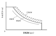
- FIG. 2 is a diagram showing an example of the relationship between the power consumption of the motor, the number of revolutions of the motor, and the torque.
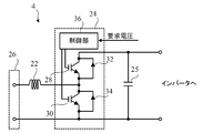
- FIG. 3 is a circuit diagram showing an example of a booster circuit.
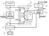
- FIG. 4 is a block diagram showing the configuration of the vehicle drive device according to the first embodiment of the present invention.
- FIG. 5 is a block diagram showing the configuration of a vehicle drive system according to a second embodiment of the present invention.
- FIG. 6 is a block diagram showing the configuration of a vehicle drive system according to a third embodiment of the present invention.
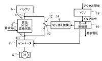
- FIG. 7 is a block diagram showing the configuration of a vehicle drive system according to a fourth embodiment of the present invention.
- FIG. 1 is a block diagram showing a basic configuration of a vehicle drive system according to an embodiment of the present invention.
- FIG. 2 is a diagram showing an example of the relationship between the power consumption of the motor,
- FIG. 8 is a block diagram showing the configuration of a vehicle drive system according to a fifth embodiment of the present invention.
- FIG. 9 is a block diagram showing the configuration of a vehicle drive system according to a sixth embodiment of the present invention.
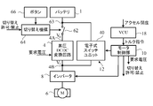
- FIG. 10 is a block diagram showing the configuration of a vehicle drive system according to a seventh embodiment of the present invention.
- FIG. 1 is a block diagram showing a basic configuration of a vehicle drive system according to an embodiment of the present invention.
- the vehicle drive device is mounted on a vehicle such as an electric vehicle or a hybrid vehicle, a two-wheeled vehicle, or another vehicle.
- the vehicle drive device includes a battery 1 which is a motive power source, and a motor unit 2 which is supplied with electric power from the battery 1 and rotationally drives wheels (not shown) of the vehicle. Although only one motor unit 2 is shown in the figure, the motor unit 2 may be provided on each drive wheel of the vehicle.
- the motor unit 2 includes a boost DCDC conversion circuit 4, a motor 6, an inverter 8, a motor control unit 10, a switch unit 12, and a position sensor 20. These components of the motor unit 2 are arranged in a common housing 14. That is, the motor unit 2 is a motor-integral motor.
- Boost DCDC converter circuit 4 is connected to the battery 1, by boosting the DC supply voltage V B of the battery 1 and supplies the boosted voltage V T to the inverter 8.
- the motor 6 is, for example, a brushless motor, and includes a rotor rotating around a rotation axis, and a stator having a field coil generating a magnetic field by a drive current corresponding to a three-phase drive voltage. Permanent magnets are attached to the rotor, and the rotor rotates in response to the magnetic field generated by the field coil. The rotation of the rotor is transmitted to the wheels.
- the inverter 8 is connected to the step-up DCDC conversion circuit 4 and drives the motor 6.
- the inverter 8 includes an IGBT (Insulated Gate Bipolar Transistor) module 16.
- IGBT module 16 according to the instruction from the motor control unit 10 performs switching of the voltage V T supplied to the inverter 8 generates a drive voltage of the three-phase supplies a drive voltage to the inverter 8.
- the IGBT module 16 includes three sets of six switching elements (IGBT elements) in order to generate three-phase drive voltages.
- IGBT element instead of the IGBT element, another switching element such as a MOSFET (Metal Oxide Semiconductor Field Effect Transistor) may be used.
- MOSFET Metal Oxide Semiconductor Field Effect Transistor
- the motor control unit 10 gives a command to the IGBT module 16 of the inverter 8 according to the rotation speed and torque required for the motor 6.
- the motor control unit 10 is connected to a VCU (Vehicle Control Unit) 18 provided in a vehicle.
- the VCU 18 gives the motor unit 2 various commands in accordance with the state of the vehicle.
- the VCU 18 supplies the motor control unit 10 with a torque command that represents the value of the torque required for the motor 6 based on the accelerator opening degree.
- the switch unit 12 is connected in parallel to the step-up DCDC converter circuit 4 between the battery 1 and the inverter 8. Switch unit 12 when turned on, electric power from the battery 1 to the inverter 8 without using the booster DCDC converter circuit 4 is supplied (power supply voltage V B is supplied). On the other hand, the switch unit 12 when it is off, the step-up DCDC converter circuit 4 and power is supplied to the inverter 8 (voltage V T, which is boosted by the booster DCDC converter circuit 4 is supplied).
- the position sensor 20 is disposed inside the motor 6.
- the position sensor 20 includes, for example, magnetic sensors, which are three Hall elements arranged at angular intervals of 120 ° around the rotor and detecting the magnetism of the rotor, and measures the angle of the rotor.
- the angle of the rotor may be measured by other means such as a rotary encoder.
- the output signal of the position sensor 20 is supplied to the motor control unit 10, and the motor control unit 10 calculates the number of rotations of the motor 6 based on the output signal of the position sensor 20.
- the motor control unit 10 calculates electric power necessary for driving the motor 6 according to the torque command value from the VCU 18 and the number of rotations of the motor 6 calculated by the motor control unit 10.
- FIG. 2 is a diagram showing an example of the relationship between the power consumption of the motor, the number of revolutions of the motor, and the torque.
- the relationship between the rotational speed of the motor 6 and the torque changes according to the power consumption of the motor 6. For example, when the power consumption is 80 kW, this relationship is as shown by a solid line in the figure, but when it is 120 kW, it is as shown by a broken line, and as 60 kW is as shown by a dotted line. Therefore, based on such a relationship, the motor control unit 10 calculates the power necessary to drive the motor 6 in accordance with the torque command value and the rotational speed of the motor 6.
- the motor control unit 10 calculates a voltage value and a current value necessary to drive the motor 6 according to the calculated required power.
- the motor control unit 10 supplies the calculated voltage value to the boost DCDC conversion circuit 4 as a required voltage.
- Boost DCDC converter circuit 4 supplies a voltage V T boosted in response to a request voltage from the motor control unit 10 to the inverter 8.
- the step-up DC / DC converter circuit 4 is a chopper-type step-up circuit, and includes a reactor 22, a circuit board 24, and a capacitor 25.
- the reactor 22 is large and easily generates heat, and thus is provided separately from the circuit board 24 for cooling.
- Boost DCDC converter circuit 4 a power supply voltage V B supplied through the power connector 26, it is boosted by the step-up ratio corresponding to the required voltage from the motor controller 10, the boosted voltage V T to the inverter 8 Supply.
- switching elements 28 and 30 such as FETs (Field Effect Transistors) that constitute a booster circuit, diodes 32 and 34 for rectification, and a control unit 36 are mounted.
- Control unit 36 in response to a request voltage from the motor control unit 10, by controlling the timing of on and off of the switching elements 28 and 30, to boost the power supply voltage V B to the requested voltage V T.
- the capacitor 25 smoothes the voltage supplied to the inverter 8.
- the use of the boost DCDC conversion circuit 4 is not always necessary. In normal vehicle operation, high torque is not required, and there is no problem even if the motor 6 is driven with electric power of 80 kW or less. Since power is lost in the step-up DCDC converter circuit 4, use of the step-up DCDC converter circuit 4 causes an increase in power consumption. In addition, when current flows constantly in the step-up DCDC conversion circuit 4, the amount of heat generation of the step-up DCDC conversion circuit 4 is large, a large cooling device is required, and the size of the vehicle drive device may be increased.
- the switch unit 12 can switch between use and non-use of the boost DCDC conversion circuit 4. Therefore, it is possible to select the power mode which is the driving state of the vehicle requiring a high torque and the power saving mode which is the state of the power saving driving. In the power saving mode in which the boost DCDC conversion circuit 4 is not used, there is no heat generation of the boost DCDC conversion circuit 4. Further, in the power mode using the step-up DCDC conversion circuit 4, since the operation period in which the step-up DCDC conversion circuit 4 is used is short, the heat generation of the step-up DCDC conversion circuit 4 is suppressed. Therefore, a large cooling device is not necessary, and downsizing of the vehicle drive device is possible.
- the motor control unit 10 directly or indirectly relates to the switching operation of the switch unit 12.
- FIG. 4 is a block diagram showing the configuration of the vehicle drive device according to the first embodiment of the present invention.
- the switch unit 12 is an electronic switch unit 40.
- the electronic switch unit 40 is a bidirectional switch unit that allows regenerative current to flow from the inverter 8 to the battery 1.
- the motor control unit 10 switches the electronic switch unit 40 off and causes the boost DC DC conversion circuit 4 to supply power to the inverter 8 to boost the voltage.
- the voltage V T boosted by the DCDC conversion circuit 4 is supplied to the inverter 8.
- the electronic switch unit 40 includes switch circuits 42 and 44.
- the switch circuit 42 has a switching element 42A and a diode 42B.
- the collector of the switching element 42A and the cathode of the diode 42B are connected to the input end 4A of the step-up DCDC conversion circuit 4.
- the switch circuit 44 has a switching element 44A and a diode 44B.
- the collector of the switching element 44A and the cathode of the diode 44B are connected to the output end 4B of the step-up DCDC conversion circuit 4.
- the emitter of the switching element 42A and the anode of the diode 42B are connected to the emitter of the switching element 44A and the anode of the diode 44B.
- the switching elements 42A and 44A are, for example, FETs.
- the motor control unit 10 can switch on and off the switching elements 42A and 44A.
- the switching element 42A When the switching element 42A is turned on, a drive current of the motor 6 flows from the battery 1 to the inverter 8 through the switching element 42A and the diode 44B. When the switching element 42A is turned off, the electronic switch unit 40 blocks the flow of drive current from the battery 1 to the inverter 8. When the switching element 44A is turned on, regenerative current flows from the inverter 8 to the battery 1 through the switching element 44A and the diode 42B. When the switching element 44A is turned off, no regenerative current flows from the inverter 8 to the battery 1.
- the switch unit 12 When the switching element 42A is on, it is considered that the switch unit 12 (electronic switch unit 40) is on. Further, when the switching element 42A is off, it is considered that the switch unit 12 (the electronic switch unit 40) is off.
- the switch unit 12 When the switch unit 12 is on, the resistances of the switching element 42A and the diode 44B are considered to be zero, so no current flows in the step-up DCDC conversion circuit 4, and the battery 1 to the inverter are not 8, via the switching element 42A and the diode 44B, power is supplied (power supply voltage V B is supplied).
- the switch unit 12 when it is off, the step-up DCDC converter circuit 4 and power is supplied to the inverter 8 (voltage V T, which is boosted by the booster DCDC converter circuit 4 is supplied).
- the motor control unit 10 switches the switch unit 12 off and causes the boost DC DC conversion circuit 4 to supply power to the inverter 8.
- the boosted voltage V T is supplied to the inverter 8.
- motor control unit 10 switches switch unit 12 on to supply power from battery 1 to inverter 8 without passing through boost DCDC conversion circuit 4. It is allowed to supply power voltage V B of the battery 1 to the inverter 8. In this way, it is possible to select a power mode that can be operated with high torque and a power saving mode that can be operated with power saving.
- the first threshold and the second threshold may, for example, be the same.
- the motor control unit 10 switches the switch unit 12 on when the vehicle retreats, and the battery is not transmitted via the boost DCDC conversion circuit 4.
- Power is supplied from 1 to the inverter 8. That is, when the vehicle is in the power mode before the vehicle retreats, it is preferable that the motor control unit 10 automatically switches the vehicle to the power saving mode when the vehicle retreats.
- the motor control unit 10 automatically switches the vehicle to the power saving mode when the vehicle retreats.
- the boosted voltage V T to supply to the inverter 8 leads to an increase in power consumption. At this time, power consumption can be reduced by switching on the switch unit 12 and supplying power from the battery 1 to the inverter 8 without passing through the step-up DCDC conversion circuit 4.
- FIG. 5 is a block diagram showing the configuration of a vehicle drive system according to a second embodiment of the present invention.
- the switch unit 12 is an electronic switch unit 40.
- the electronic switch unit 40 is a bidirectional switch unit that allows regenerative current to flow from the inverter 8 to the battery 1.
- the motor control unit 10 switches the electronic switch unit 40 off to set the inverter DC from the boost DCDC conversion circuit 4 to the inverter. 8 is supplied with power, and the voltage V T boosted by the step-up DC DC conversion circuit 4 is supplied to the inverter 8.
- the electronic switch unit 40 of the present embodiment includes two switching elements 46A and 46B.
- the switching elements 46A and 46B are, for example, FETs.
- the collector of the switching element 46A and the emitter of the switching element 46B are connected to the input end 4A of the step-up DCDC conversion circuit 4.
- the emitter of the switching element 46A and the collector of the switching element 46B are connected to the output end 4B of the step-up DCDC conversion circuit 4.
- the motor control unit 10 can switch on and off the switching elements 46A and 46B.
- the switching element 46A When the switching element 46A is turned on, a drive current of the motor 6 flows from the battery 1 to the inverter 8 through the switching element 46A. When the switching element 46A is turned off, the electronic switch unit 40 blocks the flow of drive current from the battery 1 to the inverter 8. When the switching element 46B is turned on, regenerative current flows from the inverter 8 to the battery 1 through the switching element 46B. When the switching element 46B is turned off, no regenerative current flows from the inverter 8 to the battery 1.
- the switch unit 12 When the switching element 46A is on, it is considered that the switch unit 12 (electronic switch unit 40) is on. Further, when the switching element 46A is off, it is considered that the switch unit 12 (electronic switch unit 40) is off. Since the resistance value of switching element 46A is regarded as zero when switch unit 12 is on, no current flows in boost DCDC conversion circuit 4 and switching from battery 1 to inverter 8 without passing boost DCDC conversion circuit 4 power is supplied via the element 46A (the power supply voltage V B is supplied). On the other hand, the switch unit 12 when it is off, the step-up DCDC converter circuit 4 and power is supplied to the inverter 8 (voltage V T, which is boosted by the booster DCDC converter circuit 4 is supplied).
- the motor control unit 10 switches the switch unit 12 off and supplies power from the boost DCDC conversion circuit 4 to the inverter 8. It is allowed to supply a voltage V T, which is boosted by the booster DCDC converter 4 to the inverter 8. Further, when the torque command value from VCU 18 becomes smaller than the second threshold, motor control unit 10 switches switch unit 12 on to supply power from battery 1 to inverter 8 without passing through boost DCDC conversion circuit 4. It is allowed to supply power voltage V B of the battery 1 to the inverter 8. In this way, it is possible to select a power mode that can be operated with high torque and a power saving mode that can be operated with power saving.
- the motor control unit 10 switches the switch unit 12 on when the vehicle retreats, and the battery is not transmitted via the boost DCDC conversion circuit 4. Power is supplied from 1 to the inverter 8. That is, when the vehicle is in the power mode before the vehicle retreats, it is preferable that the motor control unit 10 automatically switches the vehicle to the power saving mode when the vehicle retreats.
- FIG. 6 is a block diagram showing the configuration of a vehicle drive system according to a third embodiment of the present invention.
- the switch unit 12 is an electronic switch unit 40.
- the electronic switch unit 40 is a bidirectional switch unit that allows regenerative current to flow from the inverter 8 to the battery 1.
- the motor control unit 10 switches the electronic switch unit 40 off to set the inverter DC from the boost DCDC conversion circuit 4 to the inverter. 8 is supplied with power, and the voltage V T boosted by the step-up DC DC conversion circuit 4 is supplied to the inverter 8.
- the electronic switch unit 40 of the present embodiment includes four diodes 48A, 48B, 48C, 48D, and a switching element 50.
- the switching element 50 is, for example, an FET.
- the anode of the diode 48A and the cathode of the diode 48D are connected to the input end 4A of the boost DC DC conversion circuit 4, and the anode of the diode 48C and the cathode of the diode 48 B are connected to the output end 4B of the boost DC DC conversion circuit 4. It is done.
- the cathode of the diode 48A and the cathode of the diode 48C are connected to the collector of the switching element 50, and the anode of the diode 48D and the anode of the diode 48B are connected to the emitter of the switching element 50.
- the motor control unit 10 can switch on and off the switching element 50.
- the switching element 50 When the switching element 50 is turned on, a drive current of the motor 6 flows from the battery 1 to the inverter 8 through the diode 48A, the switching element 50 and the diode 48B. When the switching element 50 is turned off, the electronic switch unit 40 blocks the flow of drive current from the battery 1 to the inverter 8. When the switching element 50 is turned on, a regenerative current flows from the inverter 8 to the battery 1 through the diode 48C, the switching element 50 and the diode 48D. When the switching element 50 is turned off, the electronic switch unit 40 blocks the flow of the regenerative current from the inverter 8 to the battery 1.
- the switch unit 12 When the switching element 50 is on, it is considered that the switch unit 12 (electronic switch unit 40) is on. When the switching element 50 is off, it is considered that the switch unit 12 (electronic switch unit 40) is off.
- the switch unit 12 When the switch unit 12 is on, the resistances of the diode 48A, the switching element 50 and the diode 48B are considered to be zero, so no current flows in the step-up DCDC converter circuit 4 and the battery does not pass through the step-up DCDC converter circuit 1 power is supplied to the inverter 8 from (the power supply voltage V B is supplied).
- the switch unit 12 when it is off, the step-up DCDC converter circuit 4 and power is supplied to the inverter 8 (voltage V T, which is boosted by the booster DCDC converter circuit 4 is supplied).
- the motor control unit 10 switches the switch unit 12 off and supplies power from the boost DCDC conversion circuit 4 to the inverter 8. It is allowed to supply a voltage V T, which is boosted by the booster DCDC converter 4 to the inverter 8. Further, when the torque command value from VCU 18 becomes smaller than the second threshold, motor control unit 10 switches switch unit 12 on to supply power from battery 1 to inverter 8 without passing through boost DCDC conversion circuit 4. It is allowed to supply power voltage V B of the battery 1 to the inverter 8. In this way, it is possible to select a power mode that can be operated with high torque and a power saving mode that can be operated with power saving.
- the motor control unit 10 switches the switch unit 12 on when the vehicle retreats, and the battery is not transmitted via the boost DCDC conversion circuit 4. Power is supplied from 1 to the inverter 8. That is, when the vehicle is in the power mode before the vehicle retreats, it is preferable that the motor control unit 10 automatically switches the vehicle to the power saving mode when the vehicle retreats.
- FIG. 7 is a block diagram showing the configuration of a vehicle drive system according to a fourth embodiment of the present invention.
- the switch unit 12 is a mechanical switch unit 52.
- the mechanical switch unit 52 allows regenerative current to flow from the inverter 8 to the battery 1.
- the motor control unit 10 switches the mechanical switch unit 52 off to set the inverter from the boost DCDC conversion circuit 4 8 is supplied with power, and the voltage V T boosted by the step-up DC DC conversion circuit 4 is supplied to the inverter 8.
- One end of the mechanical switch unit 52 of the present embodiment is connected to the input end 4A of the boost DCDC conversion circuit 4, and the other end of the mechanical switch unit 52 is connected to the output end 4B of the boost DCDC conversion circuit 4. ing.
- a switching mechanism 54 is provided in the vehicle drive device according to the present embodiment.
- the switching mechanism 54 can switch on and off the mechanical switch unit 52 in accordance with a command from the motor control unit 10.
- the switching mechanism 54 may be, for example, a solenoid actuator, a screw mechanism, or a gear mechanism.
- the motor control unit 10 switches the switch unit 12 off and supplies power from the boost DCDC conversion circuit 4 to the inverter 8. It is allowed to supply a voltage V T, which is boosted by the booster DCDC converter 4 to the inverter 8. Further, when the torque command value from VCU 18 becomes smaller than the second threshold, motor control unit 10 switches switch unit 12 on to supply power from battery 1 to inverter 8 without passing through boost DCDC conversion circuit 4. It is allowed to supply power voltage V B of the battery 1 to the inverter 8. In this way, it is possible to select a power mode that can be operated with high torque and a power saving mode that can be operated with power saving.
- the motor control unit 10 preferably switches the mechanical switch unit 52 when no current flows in the step-up DCDC conversion circuit 4. Specifically, the motor control unit 10 preferably switches the mechanical switch unit 52 when the potentials of the input end 4A and the output end 4B of the step-up DCDC conversion circuit 4 are equal. Thereby, the life of the mechanical switch unit 52 can be extended.
- motor control unit 10 boosts the voltage boosted by boost DCDC conversion circuit 4 in the power mode. as V T is equal to the supply voltage V B, for setting the request voltage applied to the boost DCDC converter 4 to the supply voltage V B. Then, the motor control unit 10 may switch the mechanical switch unit 52 from on to off after the voltage V T becomes equal to the power supply voltage V B.
- the motor control unit 10 monitors the voltage V T, which is boosted by the booster DCDC converter circuit 4, after confirming that no current flows through the booster DCDC converter circuit 4, off the mechanical switch units 52 from ON You may switch to Alternatively, the motor control unit 10, without monitoring the voltage V T, the power mode, if you set the required voltage to the supply voltage V B immediately may switch off the mechanical switch units 52 from ON.
- the motor control unit 10 When switching from the power saving mode to the power mode, the motor control unit 10 turns off the mechanical switch unit 52 without taking special measures because no current flows in the step-up DCDC conversion circuit 4 in the power saving mode. Can be switched on.
- the motor control unit 10 switches the switch unit 12 on when the vehicle retreats, and the battery is not transmitted via the boost DCDC conversion circuit 4. Power is supplied from 1 to the inverter 8. That is, when the vehicle is in the power mode before the vehicle retreats, it is preferable that the motor control unit 10 automatically switches the vehicle to the power saving mode when the vehicle retreats. In this case, the motor control unit 10 turns the mechanical switch unit 52 off from on when no current flows in the step-up DCDC conversion circuit 4 in order to prevent the occurrence of arc discharge in the mechanical switch unit 52. It is preferable to switch. For example, when the reverse of the vehicle is selected by the shift lever or the select lever, the motor control unit 10 gives the switching mechanism 54 a command to switch on the mechanical switch unit 52 while the vehicle is stopped. Is preferred.
- FIG. 8 is a block diagram showing the configuration of a vehicle drive system according to a fifth embodiment of the present invention.
- the switch unit 12 has an electronic switch unit 40 and a mechanical switch unit 52 connected in parallel.
- the electronic switch unit 40 is a bidirectional switch unit that allows regenerative current to flow from the inverter 8 to the battery 1.
- the electronic switch unit 40 may be any of the electronic switch units 40 (see FIGS. 4 to 6) according to the first to third embodiments.
- the mechanical switch unit 52 allows regenerative current to flow from the inverter 8 to the battery 1.
- a switching mechanism 54 is provided to switch the mechanical switch unit 52 on and off.
- the mechanical switch unit 52 and the switching mechanism 54 may be the same as the mechanical switch unit 52 and the switching mechanism 54 of the fourth embodiment.
- the motor control unit 10 switches the switch unit 12 off and causes the boost DC DC conversion circuit 4 to supply power to the inverter 8.
- the boosted voltage V T is supplied to the inverter 8.
- motor control unit 10 switches switch unit 12 on to supply power from battery 1 to inverter 8 without passing through boost DCDC conversion circuit 4. It is allowed to supply power voltage V B of the battery 1 to the inverter 8. In this way, it is possible to select a power mode that can be operated with high torque and a power saving mode that can be operated with power saving.
- the motor control unit 10 preferably switches the mechanical switch unit 52 when no current flows in the step-up DCDC conversion circuit 4. Specifically, as in the fourth embodiment, the motor control unit 10 preferably switches the mechanical switch unit 52 when the potentials of the input end 4A and the output end 4B of the step-up DCDC conversion circuit 4 are equal. Thereby, the life of the mechanical switch unit 52 can be extended.
- the motor control unit 10 switches the switch unit 12 on when the vehicle retreats, and the battery is not transmitted via the boost DCDC conversion circuit 4. Power is supplied from 1 to the inverter 8. That is, when the vehicle is in the power mode before the vehicle retreats, it is preferable that the motor control unit 10 automatically switches the vehicle to the power saving mode when the vehicle retreats. In this case, the motor control unit 10 turns the mechanical switch unit 52 off from on when no current flows in the step-up DCDC conversion circuit 4 in order to prevent the occurrence of arc discharge in the mechanical switch unit 52. It is preferable to switch. For example, when the reverse of the vehicle is selected by the shift lever or the select lever, the motor control unit 10 gives the switching mechanism 54 a command to switch on the mechanical switch unit 52 while the vehicle is stopped. Is preferred.
- FIG. 9 is a block diagram showing the configuration of a vehicle drive system according to a sixth embodiment of the present invention.
- the switch unit 12 is a mechanical switch unit 52.
- the mechanical switch unit 52 allows regenerative current to flow from the inverter 8 to the battery 1.
- the on / off of the switch unit 12 (mechanical switch unit 52) is switched according to the operation of the user of the vehicle.
- mechanical switch unit 52 When mechanical switch unit 52 is switched off, the power from the step-up DCDC converter 4 to the inverter 8 is supplied, the voltage V T, which is boosted by the booster DCDC converter circuit 4 is supplied to the inverter 8. That is, a power mode that can be operated with high torque is selected.
- the mechanical switch unit 52 is switched on, the resistance value of the mechanical switch unit 52 is regarded as zero, so no current flows in the step-up DCDC conversion circuit 4 and the battery 1 is not passed through the step-up DCDC conversion circuit 4.
- power is supplied to the inverter 8, the power supply voltage V B is supplied to the inverter 8. That is, a power saving mode that can be operated with power saving is selected.
- a button 56 is provided on the dashboard, shift lever or select lever of the vehicle.
- the switching mechanism 54 for transmitting the operation of the button 56 to the mechanical switch unit 52 is provided in the vehicle drive device according to the present embodiment.
- the switching mechanism 54 can switch on and off the mechanical switch unit 52 in accordance with the operation of the button 56.
- the switching mechanism 54 may be, for example, a solenoid actuator, a screw mechanism, or a gear mechanism. In this way, it is possible to select a power mode that can be operated with high torque and a power saving mode that can be operated with power saving.
- the motor control unit 10 makes the operation of the switching mechanism 54 effective only when the vehicle is stopped. Specifically, when the vehicle stops, the motor control unit 10 supplies a switching permission signal to the switching mechanism 54. When the switching permission signal is received, the switching mechanism 54 can switch on and off the mechanical switch unit 52 in accordance with the operation of the button 56. When the vehicle starts moving, the motor control unit 10 supplies a switching prohibition signal to the switching mechanism 54. When the switching prohibition signal is received, the switching mechanism 54 can not switch the mechanical switch unit 52 on and off. Therefore, the switching mechanism 54 allows the mechanical switch unit 52 to be switched when the vehicle in which no current flows in the step-up DCDC conversion circuit 4 is stopped. Thereby, the life of the mechanical switch unit 52 can be extended.
- the motor control unit 10 switches the switch unit 12 on when the vehicle is moved backward to boost DCDC conversion. Power is supplied from the battery 1 to the inverter 8 without passing through the circuit 4. That is, when the vehicle is in the power mode before the vehicle retreats, it is preferable that the motor control unit 10 automatically switches the vehicle to the power saving mode when the vehicle retreats.
- the motor control unit 10 gives the switching mechanism 54 a command to switch on the mechanical switch unit 52 while the vehicle is stopped. Is preferred.
- the motor control unit 10 switches the switch unit 12 off after the vehicle retreats, and boost DCDC conversion is performed.
- Power is preferably supplied from the circuit 4 to the inverter 8. That is, when the vehicle is in the power mode before the vehicle retreats, it is preferable that the motor control unit 10 automatically switch the vehicle from the power saving mode to the power mode at the time of re-advance or re-advance of the vehicle .
- the motor control unit 10 automatically switch the vehicle from the power saving mode to the power mode at the time of re-advance or re-advance of the vehicle .
- the motor control unit 10 may instruct the switching mechanism 54 to switch off the mechanical switch unit 52 when the vehicle moves forward again after the vehicle retreats.
- the motor control unit 10 may instruct the switching mechanism 54 to switch the mechanical switch unit 52 off after the predetermined period has elapsed since the restart. In the power saving mode, since no current flows in the step-up DCDC conversion circuit 4, occurrence of arcing is prevented even if the mechanical switch unit 52 is switched off while the vehicle is traveling.
- the switch unit 12 is a mechanical switch unit 52.
- any of the electronic switch units 40 (see FIGS. 4 to 6) of the first to third embodiments may be used.
- the electronic switch unit 40 is switched on / off by the button 56.
- the electronic switch unit 40 may be switched on / off even if a current flows in the step-up DCDC conversion circuit 4.
- FIG. 10 is a block diagram showing the configuration of a vehicle drive system according to a seventh embodiment of the present invention.
- the switch unit 12 is an electronic switch unit 40
- the electronic switch unit 40 is a bidirectional switch unit that allows regenerative current to flow from the inverter 8 to the battery 1. is there.
- the electronic switch unit 40 may be any of the electronic switch units 40 (see FIGS. 4 to 6) according to the first to third embodiments.
- the mechanical switch unit 62 is disposed in series with the step-up DCDC conversion circuit 4. One end of the mechanical switch unit 62 is connected to the battery 1, and the other end of the mechanical switch unit 62 is connected to the input end 4 A of the step-up DCDC conversion circuit 4.
- One end of the switch unit 12 (electronic switch unit 40) is connected to the point 63 between the battery 1 and the mechanical switch unit 62, and the other end is connected to the output end 4B of the step-up DCDC conversion circuit 4. That is, the electronic switch unit 40 is connected in parallel to the combination of the mechanical switch unit 62 and the step-up DCDC conversion circuit 4 connected in series.
- the electronic switch unit 40 can switch between the power mode using the step-up DC DC conversion circuit 4 and the power saving mode not using the step-up DC DC conversion circuit 4 according to the torque command.
- the mechanical switch unit 62 is switched on / off according to the operation of the user of the vehicle.
- the mechanical switch unit 62 When the mechanical switch unit 62 is switched on, power is supplied from the battery 1 to the step-up DCDC conversion circuit 4. That is, a boost enabled mode in which boost DCDC conversion circuit 4 can be used is selected.
- the mechanical switch unit 62 When the mechanical switch unit 62 is switched off, no power is supplied to the step-up DCDC conversion circuit 4 from the battery 1. That is, the step-up impossible mode in which the use of the step-up DCDC conversion circuit 4 is invalidated is selected. In the non-boost mode, power consumption is saved.
- the motor control unit 10 switches the switch unit 12 (electronic switch unit 40) off, and the boost DCDC conversion circuit 4 starts the inverter. 8 is supplied with power, and the voltage V T boosted by the step-up DC DC conversion circuit 4 is supplied to the inverter 8. Further, when the torque command value from VCU 18 becomes smaller than the second threshold, motor control unit 10 switches switch unit 12 on to supply power from battery 1 to inverter 8 without passing through boost DCDC conversion circuit 4. It is allowed to supply power voltage V B of the battery 1 to the inverter 8.
- the step-up enable mode it is possible to select the power mode capable of operating with high torque and the power saving mode capable of operating with power saving.
- the switch unit 12 is as long as is on, power is supplied from the battery 1 to the inverter 8, the power supply voltage V B of the battery 1 is supplied to the inverter 8.
- a button 66 is provided on the dashboard, shift lever or select lever of the vehicle in order to switch on / off the mechanical switch unit 62 according to the operation of the user of the vehicle.
- the switching mechanism 64 for transmitting the operation of the button 66 to the mechanical switch unit 62 is provided in the vehicle drive device according to the present embodiment.
- the switching mechanism 64 can switch on / off the mechanical switch unit 62 in accordance with the operation of the button 66.
- the switching mechanism 64 may be, for example, a solenoid actuator, a screw mechanism, or a gear mechanism. In this way, it is possible to select the step-up impossible mode and the step-up possible mode.
- the motor control unit 10 enables the operation of the switching mechanism 64 only when the vehicle is stopped. Specifically, when the vehicle stops, the motor control unit 10 supplies a switching permission signal to the switching mechanism 64. When the switching permission signal is received, the switching mechanism 64 can switch on and off the mechanical switch unit 62 in accordance with the operation of the button 66. When the vehicle starts moving, the motor control unit 10 supplies a switching prohibition signal to the switching mechanism 64. When the switching prohibition signal is received, the switching mechanism 64 can not switch the mechanical switch unit 62 on and off. Therefore, the switching mechanism 64 allows the mechanical switch unit 62 to be switched when the vehicle in which no current flows in the step-up DCDC conversion circuit 4 is stopped. Thereby, the life of the mechanical switch unit 62 can be extended.
- motor control unit 10 switches switch unit 12 to ON when the vehicle retracts, if switch unit 12 (electronic switch unit 40) is off before the vehicle retracts in the step-up possible mode. Then, the power is supplied from the battery 1 to the inverter 8 without passing through the step-up DCDC conversion circuit 4. That is, in the pressure increase enabled mode, when the vehicle is in the power mode before the vehicle retreats, it is preferable that the motor control unit 10 automatically switches the vehicle to the power saving mode when the vehicle retreats.
- the motor control unit 10 switches the switch unit 12 off after the vehicle retreats, thereby boosting DCDC conversion.
- Power is preferably supplied from the circuit 4 to the inverter 8. That is, when the vehicle is in the power mode before the vehicle retreats, it is preferable that the motor control unit 10 automatically switches the vehicle to the power mode at the time of re-advance or re-advance of the vehicle. Thus, it is possible to automatically change the optimal mode without the need for the user of the vehicle to recognize the change in the mode.
- the motor control unit 10 may instruct the switching mechanism 64 to switch the switch unit 12 off in the case of re-forwarding after the vehicle retreats.
- the motor control unit 10 may instruct the switching mechanism 64 to switch the switch unit 12 off after the predetermined period has elapsed since the restart.
- the mechanical switch unit 62 is interposed between the battery 1 and the step-up DCDC conversion circuit 4.
- the mechanical switch unit 62 may be interposed between the step-up DCDC conversion circuit 4 and the inverter 8.
- an electronic switch unit separate from the switch unit 12 may be used instead of the mechanical switch unit 62 and the switching mechanism 64.
- the button 66 switches on / off of the electronic switch unit. In this case, even if a current flows in the step-up DCDC conversion circuit 4, the on / off of the electronic switch unit may be switched.
- the motor 6 is a brushless motor, but the motor 6 may be a three-phase induction motor.
- step-up DCDC conversion circuit 4 includes the reactor 22 and the circuit board 24, the switching elements on the circuit board 24 may be provided outside the circuit board 24.
- the first threshold and the second threshold to be compared with the torque command value may be the same or different.
- the second value may be set lower than the first value to avoid frequent on / off switching of the switching element or the mechanical switch unit.
- the first threshold and the second threshold may be fixed values or may be changed according to the driving state of the vehicle. For example, while the vehicle climbs a steep slope, the first threshold and the second threshold may be lowered to facilitate the motor 6 to exert high torque, and in other cases, the first threshold and the second threshold.
- the threshold of may be increased to increase the opportunities for power saving operation.
Landscapes
- Engineering & Computer Science (AREA)
- Power Engineering (AREA)
- Transportation (AREA)
- Mechanical Engineering (AREA)
- Life Sciences & Earth Sciences (AREA)
- Sustainable Development (AREA)
- Sustainable Energy (AREA)
- Dc-Dc Converters (AREA)
- Electric Propulsion And Braking For Vehicles (AREA)
- Inverter Devices (AREA)
Abstract
昇圧回路を必要な場合に使用することが可能な車両用駆動装置を提供する。車両用駆動装置は、バッテリに接続される昇圧回路と、昇圧回路に接続されたインバータと、インバータに駆動されるモータと、バッテリとインバータとの間に、昇圧回路に対して並列に接続されるスイッチユニットとを備える。スイッチユニットがオンの場合に、バッテリからインバータに電力が供給され、スイッチユニットがオフの場合に、昇圧回路からインバータに電力が供給される。
Description
本発明は、モータを有する車両用駆動装置に関する。
電気自動車またはハイブリッド自動車には、車輪を回転させるモータが設けられている。モータを有する車両用駆動装置には、一般的に、電圧を増加させる昇圧回路が設けられている。
例えば、特開2016-20864号公報は、2つのバッテリのそれぞれに2つの昇圧回路が接続された電力変換システムを開示する。特開2016-20864号公報に開示された技術では、2つのバッテリに対する昇降圧が並列に行われる。
昇圧回路は、車両の急加速時など高トルクが必要な場合に備えて、電圧を増加させる。しかし、昇圧回路では電力が損失されるので、昇圧回路の使用は消費電力の増大の原因となる。また、昇圧回路に常に電流が流れていると、昇圧回路の発熱量が多く、大きな冷却装置が必要となり、車両用駆動装置のサイズが大きくなってしまうおそれがある。
そこで、本発明は、昇圧回路を必要な場合に使用することが可能な車両用駆動装置を提供することを目的とする。
本発明のある態様に係る車両用駆動装置は、バッテリに接続される昇圧回路と、前記昇圧回路に接続されたインバータと、前記インバータに駆動されるモータと、前記バッテリと前記インバータとの間に、前記昇圧回路に対して並列に接続されるスイッチユニットとを備え、前記スイッチユニットがオンの場合に、前記バッテリから前記インバータに電力が供給され、前記スイッチユニットがオフの場合に、前記昇圧回路から前記インバータに電力が供給される。
上記態様においては、スイッチユニットによって昇圧回路の使用と不使用を切り替えることが可能である。したがって、高トルクが必要な車両の運転状態と、省電力運転の状態の選択が可能である。昇圧回路を使用しない省電力運転では、昇圧回路の発熱がないため、大きな冷却装置が不要であり、車両用駆動装置の小型化が可能である。
以下、添付の図面を参照しながら本発明に係る複数の実施の形態を説明する。
<基本構成>
図1は、本発明の実施形態に係る車両用駆動装置の基本構成を示すブロック図である。車両用駆動装置は、電気自動車またはハイブリッド自動車などの自動車、二輪車、またはその他の車両に搭載されている。
<基本構成>
図1は、本発明の実施形態に係る車両用駆動装置の基本構成を示すブロック図である。車両用駆動装置は、電気自動車またはハイブリッド自動車などの自動車、二輪車、またはその他の車両に搭載されている。
車両用駆動装置は、動力源であるバッテリ1と、バッテリ1から電力が供給されて、車両の車輪(図示せず)を回転駆動させるモータユニット2とを備える。図においては、1つのモータユニット2のみが示されているが、モータユニット2は、車両の各駆動輪に設けられてもよい。
モータユニット2は、昇圧DCDC変換回路4、モータ6、インバータ8、モータ制御部10、スイッチユニット12、および位置センサ20を備える。モータユニット2のこれらの構成要素は、共通の筐体14内に配置されている。すなわち、モータユニット2は機電一体型のモータである。
昇圧DCDC変換回路4は、バッテリ1に接続され、バッテリ1の直流の電源電圧VBを昇圧して、昇圧された電圧VTをインバータ8に供給する。
モータ6は、例えば、ブラシレスモータであって、回転軸を中心として回転するロータと、三相の駆動電圧に応じた駆動電流によって磁界を発生する界磁コイルを有するステータとを備える。ロータには、永久磁石が取り付けられており、界磁コイルにより発生される磁界に応じて、ロータは回転する。ロータの回転は車輪に伝達される。
インバータ8は、昇圧DCDC変換回路4に接続されており、モータ6を駆動する。インバータ8は、IGBT(Insulated Gate Bipolar Transistor)モジュール16を備える。IGBTモジュール16は、モータ制御部10からの指令に従って、インバータ8に供給される電圧VTのスイッチングを行って三相の駆動電圧を生成し、駆動電圧をインバータ8に供給する。IGBTモジュール16は、三相の駆動電圧を生成するため、3組6個のスイッチング素子(IGBT素子)を備えている。IGBT素子の代わりにMOSFET(Metal Oxide Semiconductor Field Effect Transistor)等の他のスイッチング素子を用いてもよい。
モータ制御部10は、モータ6に必要な回転速度およびトルクに応じて、インバータ8のIGBTモジュール16に指令を与える。
モータ制御部10には、車両に設けられたVCU(Vehicle Control Unit)18が接続されている。VCU18は、車両の状態に応じて、モータユニット2に各種の指令を与える。例えば、VCU18は、アクセル開度に基づいて、モータ6に必要なトルクの値を表すトルク指令をモータ制御部10に供給する。
スイッチユニット12は、バッテリ1とインバータ8との間に、昇圧DCDC変換回路4に対して並列に接続されている。スイッチユニット12がオンの場合に、昇圧DCDC変換回路4を介さずにバッテリ1からインバータ8に電力が供給される(電源電圧VBが供給される)。一方、スイッチユニット12がオフの場合に、昇圧DCDC変換回路4からインバータ8に電力が供給される(昇圧DCDC変換回路4で昇圧された電圧VTが供給される)。
位置センサ20は、モータ6の内部に配置されている。位置センサ20は、例えばロータの周囲に120°の角間隔をおいて配置され、ロータの磁気を検出する3つのホール素子である磁気センサを備え、ロータの角度を測定する。ロータリーエンコーダ等の他の手段によってロータの角度を測定するようにしてもよい。位置センサ20の出力信号は、モータ制御部10に供給され、モータ制御部10は、位置センサ20の出力信号に基づいて、モータ6の回転数を算出する。
モータ制御部10は、VCU18からのトルク指令値と、モータ制御部10で算出したモータ6の回転数に応じて、モータ6の駆動に必要な電力を算出する。図2は、モータの消費電力とモータの回転数とトルクとの関係の例を示す図である。モータ6の回転数とトルクとの関係は、モータ6の消費電力に応じて変化する。例えば、消費電力が80kWでは、この関係は同図中の実線のようになるが、120kWでは破線で示すようになり、60kWでは点線で示すようになる。このため、モータ制御部10は、このような関係に基づいて、トルク指令値とモータ6の回転数に応じて、モータ6の駆動に必要な電力を算出する。
さらに、モータ制御部10は、算出した必要電力に応じて、モータ6の駆動に必要な電圧値と電流値を算出する。昇圧DCDC変換回路4が使用される場合には、モータ制御部10は、算出した電圧値を要求電圧として昇圧DCDC変換回路4に供給する。昇圧DCDC変換回路4は、モータ制御部10からの要求電圧に応じて昇圧された電圧VTをインバータ8に供給する。
昇圧DCDC変換回路4は、例えば図3に示すように、チョッパ形の昇圧回路であり、リアクトル22と、回路基板24と、キャパシタ25とを備える。リアクトル22は、大型であり、発熱しやすいため、冷却のために回路基板24とは別に設けられている。昇圧DCDC変換回路4は、電源コネクタ26を介して供給される電源電圧VBを、モータ制御部10からの要求電圧に応じた昇圧比で昇圧して、昇圧された電圧VTをインバータ8に供給する。回路基板24には、昇圧回路を構成するFET(Field Effect Transistor)等のスイッチング素子28,30、整流用のダイオード32,34、および制御部36が実装されている。制御部36は、モータ制御部10からの要求電圧に応じて、スイッチング素子28,30のオン・オフのタイミングを制御することにより、電源電圧VBを要求された電圧VTに昇圧する。キャパシタ25は、インバータ8に供給する電圧を平滑化する。
しかし、昇圧DCDC変換回路4の使用は常に必要であるとは限らない。通常の車両の運転では、高トルクは必要とされず、80kW以下の電力でモータ6を駆動しても問題ない。昇圧DCDC変換回路4では電力が損失されるので、昇圧DCDC変換回路4の使用は消費電力の増大の原因となる。また、昇圧DCDC変換回路4に常に電流が流れていると、昇圧DCDC変換回路4の発熱量が多く、大きな冷却装置が必要となり、車両用駆動装置のサイズが大きくなってしまうおそれがある。
他方、車両の急加速時など高トルクが必要な場合には、80kWより大きい電力でモータ6を駆動するのが望ましい。すなわち、図2において斜線で示す範囲を用いるのが望ましい。しかしながら、高トルクが必要な期間は通常は短い。
以下に説明する本発明の実施形態においては、スイッチユニット12によって、昇圧DCDC変換回路4の使用と不使用を切り替えることが可能である。したがって、高トルクが必要な車両の運転状態であるパワーモードと、省電力運転の状態である省電力モードの選択が可能である。昇圧DCDC変換回路4を使用しない省電力モードでは、昇圧DCDC変換回路4の発熱がない。また、昇圧DCDC変換回路4を使用するパワーモードでは、昇圧DCDC変換回路4を使用する運転期間は短いため、昇圧DCDC変換回路4の発熱は抑制される。したがって、大きな冷却装置が不要であり、車両用駆動装置の小型化が可能である。
以下に説明する複数の実施形態において、モータ制御部10は、スイッチユニット12の切り替え動作に直接的または間接的に関わる。
<第1実施形態>
図4は、本発明の第1実施形態に係る車両用駆動装置の構成を示すブロック図である。本実施形態に係る車両用駆動装置において、スイッチユニット12は、電子式スイッチユニット40である。電子式スイッチユニット40は、インバータ8からバッテリ1に回生電流が流れることを許容する双方向スイッチユニットである。本実施形態では、モータ制御部10は、VCU18からのトルク指令値が閾値より大きい場合に、電子式スイッチユニット40をオフに切り替えて、昇圧DCDC変換回路4からインバータ8に電力を供給させ、昇圧DCDC変換回路4で昇圧された電圧VTをインバータ8に供給する。
図4は、本発明の第1実施形態に係る車両用駆動装置の構成を示すブロック図である。本実施形態に係る車両用駆動装置において、スイッチユニット12は、電子式スイッチユニット40である。電子式スイッチユニット40は、インバータ8からバッテリ1に回生電流が流れることを許容する双方向スイッチユニットである。本実施形態では、モータ制御部10は、VCU18からのトルク指令値が閾値より大きい場合に、電子式スイッチユニット40をオフに切り替えて、昇圧DCDC変換回路4からインバータ8に電力を供給させ、昇圧DCDC変換回路4で昇圧された電圧VTをインバータ8に供給する。
電子式スイッチユニット40は、スイッチ回路42,44を備える。スイッチ回路42は、スイッチング素子42Aとダイオード42Bを有する。スイッチング素子42Aのコレクタとダイオード42Bのカソードは、昇圧DCDC変換回路4の入力端4Aに接続されている。スイッチ回路44は、スイッチング素子44Aとダイオード44Bを有する。スイッチング素子44Aのコレクタとダイオード44Bのカソードは、昇圧DCDC変換回路4の出力端4Bに接続されている。スイッチング素子42Aのエミッタとダイオード42Bのアノードは、スイッチング素子44Aのエミッタとダイオード44Bのアノードに接続されている。スイッチング素子42A,44Aは、例えばFETである。モータ制御部10は、スイッチング素子42A,44Aのオン・オフを切り替えることができる。
スイッチング素子42Aをオンにすると、バッテリ1からスイッチング素子42Aおよびダイオード44Bを経てインバータ8にモータ6の駆動電流が流れる。スイッチング素子42Aをオフにすると、バッテリ1からインバータ8への駆動電流の流れを電子式スイッチユニット40は阻止する。スイッチング素子44Aをオンにすると、インバータ8からスイッチング素子44Aおよびダイオード42Bを経てバッテリ1に回生電流が流れる。スイッチング素子44Aをオフにすると、インバータ8からバッテリ1に回生電流は流れない。
スイッチング素子42Aがオンの場合をスイッチユニット12(電子式スイッチユニット40)がオンであると考える。また、スイッチング素子42Aがオフの場合をスイッチユニット12(電子式スイッチユニット40)がオフであると考える。スイッチユニット12がオンの場合に、スイッチング素子42Aおよびダイオード44Bの抵抗値はゼロとみなされるので、昇圧DCDC変換回路4には電流が流れず、昇圧DCDC変換回路4を介さずにバッテリ1からインバータ8に、スイッチング素子42Aおよびダイオード44Bを介して、電力が供給される(電源電圧VBが供給される)。一方、スイッチユニット12がオフの場合に、昇圧DCDC変換回路4からインバータ8に電力が供給される(昇圧DCDC変換回路4で昇圧された電圧VTが供給される)。
モータ制御部10は、VCU18からのトルク指令値が第1の閾値より大きくなると、スイッチユニット12をオフに切り替えて、昇圧DCDC変換回路4からインバータ8に電力を供給させ、昇圧DCDC変換回路4で昇圧された電圧VTをインバータ8に供給する。また、モータ制御部10は、VCU18からのトルク指令値が第2の閾値より小さくなると、スイッチユニット12をオンに切り替えて、昇圧DCDC変換回路4を介さずにバッテリ1からインバータ8に電力を供給させ、バッテリ1の電源電圧VBをインバータ8に供給する。このようにして、高トルクで運転可能なパワーモードと、省電力で運転可能な省電力モードの選択が可能である。第1の閾値および第2の閾値は、例えば、同じであってよい。
また、好ましくは、モータ制御部10は、車両の後退前に、スイッチユニット12がオフであれば、車両の後退時に、スイッチユニット12をオンに切り替えて、昇圧DCDC変換回路4を介さずにバッテリ1からインバータ8に電力を供給させる。すなわち、車両の後退前に車両がパワーモードであった場合には、車両の後退時に、モータ制御部10は、自動的に車両を省電力モードに切り替えるのが好ましい。車両の駐車などのために、車両が後退する際に、昇圧DCDC変換回路4を用いて、昇圧された電圧VTをインバータ8に供給するのは、消費電力の増大につながる。この際に、スイッチユニット12をオンに切り替えて、昇圧DCDC変換回路4を介さずにバッテリ1からインバータ8に電力を供給させることにより、消費電力を節減することができる。
<第2実施形態>
図5は、本発明の第2実施形態に係る車両用駆動装置の構成を示すブロック図である。本実施形態に係る車両用駆動装置において、スイッチユニット12は、電子式スイッチユニット40である。電子式スイッチユニット40は、インバータ8からバッテリ1に回生電流が流れることを許容する双方向スイッチユニットである。第1実施形態と同様に、本実施形態では、モータ制御部10は、VCU18からのトルク指令値が閾値より大きい場合に、電子式スイッチユニット40をオフに切り替えて、昇圧DCDC変換回路4からインバータ8に電力を供給させ、昇圧DCDC変換回路4で昇圧された電圧VTをインバータ8に供給する。
図5は、本発明の第2実施形態に係る車両用駆動装置の構成を示すブロック図である。本実施形態に係る車両用駆動装置において、スイッチユニット12は、電子式スイッチユニット40である。電子式スイッチユニット40は、インバータ8からバッテリ1に回生電流が流れることを許容する双方向スイッチユニットである。第1実施形態と同様に、本実施形態では、モータ制御部10は、VCU18からのトルク指令値が閾値より大きい場合に、電子式スイッチユニット40をオフに切り替えて、昇圧DCDC変換回路4からインバータ8に電力を供給させ、昇圧DCDC変換回路4で昇圧された電圧VTをインバータ8に供給する。
本実施形態の電子式スイッチユニット40は、2つのスイッチング素子46A,46Bを備える。スイッチング素子46A,46Bは、例えばFETである。スイッチング素子46Aのコレクタとスイッチング素子46Bのエミッタは、昇圧DCDC変換回路4の入力端4Aに接続されている。スイッチング素子46Aのエミッタとスイッチング素子46Bのコレクタは、昇圧DCDC変換回路4の出力端4Bに接続されている。モータ制御部10は、スイッチング素子46A,46Bのオン・オフを切り替えることができる。
スイッチング素子46Aをオンにすると、バッテリ1からスイッチング素子46Aを経てインバータ8にモータ6の駆動電流が流れる。スイッチング素子46Aをオフにすると、バッテリ1からインバータ8への駆動電流の流れを電子式スイッチユニット40は阻止する。スイッチング素子46Bをオンにすると、インバータ8からスイッチング素子46Bを経てバッテリ1に回生電流が流れる。スイッチング素子46Bをオフにすると、インバータ8からバッテリ1に回生電流は流れない。
スイッチング素子46Aがオンの場合をスイッチユニット12(電子式スイッチユニット40)がオンであると考える。また、スイッチング素子46Aがオフの場合をスイッチユニット12(電子式スイッチユニット40)がオフであると考える。スイッチユニット12がオンの場合に、スイッチング素子46Aの抵抗値はゼロとみなされるので、昇圧DCDC変換回路4には電流が流れず、昇圧DCDC変換回路4を介さずにバッテリ1からインバータ8にスイッチング素子46Aを介して電力が供給される(電源電圧VBが供給される)。一方、スイッチユニット12がオフの場合に、昇圧DCDC変換回路4からインバータ8に電力が供給される(昇圧DCDC変換回路4で昇圧された電圧VTが供給される)。
第1実施形態と同様に、モータ制御部10は、VCU18からのトルク指令値が第1の閾値より大きくなると、スイッチユニット12をオフに切り替えて、昇圧DCDC変換回路4からインバータ8に電力を供給させ、昇圧DCDC変換回路4で昇圧された電圧VTをインバータ8に供給する。また、モータ制御部10は、VCU18からのトルク指令値が第2の閾値より小さくなると、スイッチユニット12をオンに切り替えて、昇圧DCDC変換回路4を介さずにバッテリ1からインバータ8に電力を供給させ、バッテリ1の電源電圧VBをインバータ8に供給する。このようにして、高トルクで運転可能なパワーモードと、省電力で運転可能な省電力モードの選択が可能である。
また、好ましくは、モータ制御部10は、車両の後退前に、スイッチユニット12がオフであれば、車両の後退時に、スイッチユニット12をオンに切り替えて、昇圧DCDC変換回路4を介さずにバッテリ1からインバータ8に電力を供給させる。すなわち、車両の後退前に車両がパワーモードであった場合には、車両の後退時に、モータ制御部10は、自動的に車両を省電力モードに切り替えるのが好ましい。
<第3実施形態>
図6は、本発明の第3実施形態に係る車両用駆動装置の構成を示すブロック図である。本実施形態に係る車両用駆動装置において、スイッチユニット12は、電子式スイッチユニット40である。電子式スイッチユニット40は、インバータ8からバッテリ1に回生電流が流れることを許容する双方向スイッチユニットである。第1実施形態と同様に、本実施形態では、モータ制御部10は、VCU18からのトルク指令値が閾値より大きい場合に、電子式スイッチユニット40をオフに切り替えて、昇圧DCDC変換回路4からインバータ8に電力を供給させ、昇圧DCDC変換回路4で昇圧された電圧VTをインバータ8に供給する。
図6は、本発明の第3実施形態に係る車両用駆動装置の構成を示すブロック図である。本実施形態に係る車両用駆動装置において、スイッチユニット12は、電子式スイッチユニット40である。電子式スイッチユニット40は、インバータ8からバッテリ1に回生電流が流れることを許容する双方向スイッチユニットである。第1実施形態と同様に、本実施形態では、モータ制御部10は、VCU18からのトルク指令値が閾値より大きい場合に、電子式スイッチユニット40をオフに切り替えて、昇圧DCDC変換回路4からインバータ8に電力を供給させ、昇圧DCDC変換回路4で昇圧された電圧VTをインバータ8に供給する。
本実施形態の電子式スイッチユニット40は、4つのダイオード48A,48B,48C,48Dと、スイッチング素子50を備える。スイッチング素子50は、例えばFETである。ダイオード48Aのアノードと、ダイオード48Dのカソードは、昇圧DCDC変換回路4の入力端4Aに接続されており、ダイオード48Cのアノードと、ダイオード48Bのカソードは、昇圧DCDC変換回路4の出力端4Bに接続されている。ダイオード48Aのカソードとダイオード48Cのカソードは、スイッチング素子50のコレクタに接続され、ダイオード48Dのアノードとダイオード48Bのアノードは、スイッチング素子50のエミッタに接続されている。モータ制御部10は、スイッチング素子50のオン・オフを切り替えることができる。
スイッチング素子50をオンにすると、バッテリ1からダイオード48A、スイッチング素子50およびダイオード48Bを経てインバータ8にモータ6の駆動電流が流れる。スイッチング素子50をオフにすると、バッテリ1からインバータ8への駆動電流の流れを電子式スイッチユニット40は阻止する。また、スイッチング素子50をオンにすると、インバータ8からダイオード48C、スイッチング素子50およびダイオード48Dを経てバッテリ1に回生電流が流れる。スイッチング素子50をオフにすると、インバータ8からバッテリ1への回生電流の流れを電子式スイッチユニット40は阻止する。
スイッチング素子50がオンの場合をスイッチユニット12(電子式スイッチユニット40)がオンであると考える。また、スイッチング素子50がオフの場合をスイッチユニット12(電子式スイッチユニット40)がオフであると考える。スイッチユニット12がオンの場合に、ダイオード48A、スイッチング素子50およびダイオード48Bの抵抗値はゼロとみなされるので、昇圧DCDC変換回路4には電流が流れず、昇圧DCDC変換回路4を介さずにバッテリ1からインバータ8に電力が供給される(電源電圧VBが供給される)。一方、スイッチユニット12がオフの場合に、昇圧DCDC変換回路4からインバータ8に電力が供給される(昇圧DCDC変換回路4で昇圧された電圧VTが供給される)。
第1実施形態と同様に、モータ制御部10は、VCU18からのトルク指令値が第1の閾値より大きくなると、スイッチユニット12をオフに切り替えて、昇圧DCDC変換回路4からインバータ8に電力を供給させ、昇圧DCDC変換回路4で昇圧された電圧VTをインバータ8に供給する。また、モータ制御部10は、VCU18からのトルク指令値が第2の閾値より小さくなると、スイッチユニット12をオンに切り替えて、昇圧DCDC変換回路4を介さずにバッテリ1からインバータ8に電力を供給させ、バッテリ1の電源電圧VBをインバータ8に供給する。このようにして、高トルクで運転可能なパワーモードと、省電力で運転可能な省電力モードの選択が可能である。
また、好ましくは、モータ制御部10は、車両の後退前に、スイッチユニット12がオフであれば、車両の後退時に、スイッチユニット12をオンに切り替えて、昇圧DCDC変換回路4を介さずにバッテリ1からインバータ8に電力を供給させる。すなわち、車両の後退前に車両がパワーモードであった場合には、車両の後退時に、モータ制御部10は、自動的に車両を省電力モードに切り替えるのが好ましい。
<第4実施形態>
図7は、本発明の第4実施形態に係る車両用駆動装置の構成を示すブロック図である。本実施形態に係る車両用駆動装置において、スイッチユニット12は、機械式スイッチユニット52である。機械式スイッチユニット52は、インバータ8からバッテリ1に回生電流が流れることを許容する。第1実施形態と同様に、本実施形態では、モータ制御部10は、VCU18からのトルク指令値が閾値より大きい場合に、機械式スイッチユニット52をオフに切り替えて、昇圧DCDC変換回路4からインバータ8に電力を供給させ、昇圧DCDC変換回路4で昇圧された電圧VTをインバータ8に供給する。
図7は、本発明の第4実施形態に係る車両用駆動装置の構成を示すブロック図である。本実施形態に係る車両用駆動装置において、スイッチユニット12は、機械式スイッチユニット52である。機械式スイッチユニット52は、インバータ8からバッテリ1に回生電流が流れることを許容する。第1実施形態と同様に、本実施形態では、モータ制御部10は、VCU18からのトルク指令値が閾値より大きい場合に、機械式スイッチユニット52をオフに切り替えて、昇圧DCDC変換回路4からインバータ8に電力を供給させ、昇圧DCDC変換回路4で昇圧された電圧VTをインバータ8に供給する。
本実施形態の機械式スイッチユニット52の一端は、昇圧DCDC変換回路4の入力端4Aに接続されており、機械式スイッチユニット52の他端は、昇圧DCDC変換回路4の出力端4Bに接続されている。
機械式スイッチユニット52のオン・オフを切り替えるため、本実施形態に係る車両用駆動装置には、切り替え機構54が設けられている。切り替え機構54は、モータ制御部10からの指令に応じて、機械式スイッチユニット52のオン・オフを切り替えることができる。切り替え機構54は、例えば、ソレノイドアクチュエータでもよいし、ネジ機構でもよいし、歯車機構でもよい。
機械式スイッチユニット52をオンにすると、バッテリ1から機械式スイッチユニット52を経てインバータ8にモータ6の駆動電流が流れる。機械式スイッチユニット52をオフにすると、バッテリ1からインバータ8への駆動電流の流れを機械式スイッチユニット52は阻止する。また、機械式スイッチユニット52をオンにすると、インバータ8から機械式スイッチユニット52を経てバッテリ1に回生電流が流れる。機械式スイッチユニット52をオフにすると、インバータ8からバッテリ1への回生電流の流れを機械式スイッチユニット52は阻止する。
スイッチユニット12(機械式スイッチユニット52)がオンの場合に、機械式スイッチユニット52の抵抗値はゼロとみなされるので、昇圧DCDC変換回路4には電流が流れず、昇圧DCDC変換回路4を介さずにバッテリ1からインバータ8に、機械式スイッチユニット52を介して、電力が供給される(電源電圧VBが供給される)。一方、スイッチユニット12がオフの場合に、昇圧DCDC変換回路4からインバータ8に電力が供給される(昇圧DCDC変換回路4で昇圧された電圧VTが供給される)。
第1実施形態と同様に、モータ制御部10は、VCU18からのトルク指令値が第1の閾値より大きくなると、スイッチユニット12をオフに切り替えて、昇圧DCDC変換回路4からインバータ8に電力を供給させ、昇圧DCDC変換回路4で昇圧された電圧VTをインバータ8に供給する。また、モータ制御部10は、VCU18からのトルク指令値が第2の閾値より小さくなると、スイッチユニット12をオンに切り替えて、昇圧DCDC変換回路4を介さずにバッテリ1からインバータ8に電力を供給させ、バッテリ1の電源電圧VBをインバータ8に供給する。このようにして、高トルクで運転可能なパワーモードと、省電力で運転可能な省電力モードの選択が可能である。
但し、機械式スイッチユニット52でのアーク放電の発生を防止するため、モータ制御部10は、昇圧DCDC変換回路4に電流が流れていない場合に、機械式スイッチユニット52を切り替えるのが好ましい。具体的には、モータ制御部10は、昇圧DCDC変換回路4の入力端4Aと出力端4Bの電位が等しい場合に、機械式スイッチユニット52を切り替えるのが好ましい。これにより、機械式スイッチユニット52の寿命を延ばすことができる。
したがって、昇圧DCDC変換回路4を使用するパワーモードから昇圧DCDC変換回路4を使用しない省電力モードに切り替える場合には、パワーモードにおいて、モータ制御部10は、昇圧DCDC変換回路4で昇圧された電圧VTが電源電圧VBに等しくなるように、昇圧DCDC変換回路4に与える上記の要求電圧を電源電圧VBに設定する。そして、モータ制御部10は、電圧VTが電源電圧VBに等しくなった後に、機械式スイッチユニット52をオンからオフに切り替えてもよい。すなわち、モータ制御部10は、昇圧DCDC変換回路4で昇圧された電圧VTを監視し、昇圧DCDC変換回路4に電流が流れていないことを確認した後に、機械式スイッチユニット52をオンからオフに切り替えてもよい。あるいは、モータ制御部10は、電圧VTを監視せずに、パワーモードにおいて、要求電圧を電源電圧VBに設定したら直ちに、機械式スイッチユニット52をオンからオフに切り替えてもよい。
省電力モードからパワーモードに切り替える場合には、省電力モードでは昇圧DCDC変換回路4に電流が流れていないため、モータ制御部10は、特段の措置を採らずに、機械式スイッチユニット52をオフからオンに切り替えることができる。
また、好ましくは、モータ制御部10は、車両の後退前に、スイッチユニット12がオフであれば、車両の後退時に、スイッチユニット12をオンに切り替えて、昇圧DCDC変換回路4を介さずにバッテリ1からインバータ8に電力を供給させる。すなわち、車両の後退前に車両がパワーモードであった場合には、車両の後退時に、モータ制御部10は、自動的に車両を省電力モードに切り替えるのが好ましい。この場合、モータ制御部10は、機械式スイッチユニット52でのアーク放電の発生を防止するために、昇圧DCDC変換回路4に電流が流れていない場合に、機械式スイッチユニット52をオフからオンに切り替えるのが好ましい。例えば、シフトレバーまたはセレクトレバーで車両の後退が選択されると、車両が停止している間に、モータ制御部10は、切り替え機構54に、機械式スイッチユニット52をオンに切り替える指令を与えるのが好ましい。
<第5実施形態>
図8は、本発明の第5実施形態に係る車両用駆動装置の構成を示すブロック図である。本実施形態に係る車両用駆動装置において、スイッチユニット12は、並列に接続された電子式スイッチユニット40と機械式スイッチユニット52を有する。
図8は、本発明の第5実施形態に係る車両用駆動装置の構成を示すブロック図である。本実施形態に係る車両用駆動装置において、スイッチユニット12は、並列に接続された電子式スイッチユニット40と機械式スイッチユニット52を有する。
電子式スイッチユニット40は、インバータ8からバッテリ1に回生電流が流れることを許容する双方向スイッチユニットである。電子式スイッチユニット40は、第1~第3実施形態の電子式スイッチユニット40(図4~図6参照)のいずれでもよい。
機械式スイッチユニット52は、インバータ8からバッテリ1に回生電流が流れることを許容する。機械式スイッチユニット52のオン・オフを切り替えるため、切り替え機構54が設けられている。機械式スイッチユニット52と切り替え機構54は、第4実施形態の機械式スイッチユニット52と切り替え機構54と同じでよい。
電子式スイッチユニット40と機械式スイッチユニット52の両方がオンの場合をスイッチユニット12がオンであると考える。また、電子式スイッチユニット40と機械式スイッチユニット52の両方がオフの場合をスイッチユニット12がオフであると考える。電子式スイッチユニット40と機械式スイッチユニット52の両方またはいずれか一方がオンの場合に、昇圧DCDC変換回路4には電流が流れず、昇圧DCDC変換回路4を介さずにバッテリ1からインバータ8に電力が供給される(電源電圧VBが供給される)。スイッチユニット12がオフの場合(電子式スイッチユニット40と機械式スイッチユニット52の両方がオフの場合)に、昇圧DCDC変換回路4からインバータ8に電力が供給される(昇圧DCDC変換回路4で昇圧された電圧VTが供給される)。
モータ制御部10は、VCU18からのトルク指令値が第1の閾値より大きくなると、スイッチユニット12をオフに切り替えて、昇圧DCDC変換回路4からインバータ8に電力を供給させ、昇圧DCDC変換回路4で昇圧された電圧VTをインバータ8に供給する。また、モータ制御部10は、VCU18からのトルク指令値が第2の閾値より小さくなると、スイッチユニット12をオンに切り替えて、昇圧DCDC変換回路4を介さずにバッテリ1からインバータ8に電力を供給させ、バッテリ1の電源電圧VBをインバータ8に供給する。このようにして、高トルクで運転可能なパワーモードと、省電力で運転可能な省電力モードの選択が可能である。
但し、機械式スイッチユニット52でのアーク放電の発生を防止するため、モータ制御部10は、昇圧DCDC変換回路4に電流が流れていない場合に、機械式スイッチユニット52を切り替えるのが好ましい。具体的には、第4実施形態と同様に、モータ制御部10は、昇圧DCDC変換回路4の入力端4Aと出力端4Bの電位が等しい場合に、機械式スイッチユニット52を切り替えるのが好ましい。これにより、機械式スイッチユニット52の寿命を延ばすことができる。
また、好ましくは、モータ制御部10は、車両の後退前に、スイッチユニット12がオフであれば、車両の後退時に、スイッチユニット12をオンに切り替えて、昇圧DCDC変換回路4を介さずにバッテリ1からインバータ8に電力を供給させる。すなわち、車両の後退前に車両がパワーモードであった場合には、車両の後退時に、モータ制御部10は、自動的に車両を省電力モードに切り替えるのが好ましい。この場合、モータ制御部10は、機械式スイッチユニット52でのアーク放電の発生を防止するために、昇圧DCDC変換回路4に電流が流れていない場合に、機械式スイッチユニット52をオフからオンに切り替えるのが好ましい。例えば、シフトレバーまたはセレクトレバーで車両の後退が選択されると、車両が停止している間に、モータ制御部10は、切り替え機構54に、機械式スイッチユニット52をオンに切り替える指令を与えるのが好ましい。
<第6実施形態>
図9は、本発明の第6実施形態に係る車両用駆動装置の構成を示すブロック図である。本実施形態に係る車両用駆動装置において、スイッチユニット12は、機械式スイッチユニット52である。機械式スイッチユニット52は、インバータ8からバッテリ1に回生電流が流れることを許容する。
図9は、本発明の第6実施形態に係る車両用駆動装置の構成を示すブロック図である。本実施形態に係る車両用駆動装置において、スイッチユニット12は、機械式スイッチユニット52である。機械式スイッチユニット52は、インバータ8からバッテリ1に回生電流が流れることを許容する。
本実施形態では、車両の使用者の操作に応じて、スイッチユニット12(機械式スイッチユニット52)のオン・オフを切り替える。機械式スイッチユニット52がオフに切り替えられると、昇圧DCDC変換回路4からインバータ8に電力が供給され、昇圧DCDC変換回路4で昇圧された電圧VTがインバータ8に供給される。すなわち、高トルクで運転可能なパワーモードが選択される。機械式スイッチユニット52がオンに切り替えられると、機械式スイッチユニット52の抵抗値はゼロとみなされるので、昇圧DCDC変換回路4には電流が流れず、昇圧DCDC変換回路4を介さずにバッテリ1からインバータ8に電力が供給され、電源電圧VBがインバータ8に供給される。すなわち、省電力で運転可能な省電力モードが選択される。
車両の使用者の操作に応じて、スイッチユニット12(機械式スイッチユニット52)のオン・オフを切り替えるため、車両のダッシュボード、シフトレバーまたはセレクトレバーに、ボタン56が設けられている。また、本実施形態に係る車両用駆動装置には、ボタン56の動作を機械式スイッチユニット52に伝達する切り替え機構54が設けられている。切り替え機構54は、ボタン56の動作に応じて、機械式スイッチユニット52のオン・オフを切り替えることができる。切り替え機構54は、例えば、ソレノイドアクチュエータでもよいし、ネジ機構でもよいし、歯車機構でもよい。このようにして、高トルクで運転可能なパワーモードと、省電力で運転可能な省電力モードの選択が可能である。
但し、機械式スイッチユニット52でのアーク放電の発生を防止するため、昇圧DCDC変換回路4に電流が流れていない場合に、機械式スイッチユニット52を切り替えるのが好ましい。そこで、本実施形態では、モータ制御部10は、車両が停止している際にのみ、切り替え機構54の動作を有効にする。具体的には、車両が停止すると、モータ制御部10は切り替え許可信号を切り替え機構54に供給する。切り替え許可信号を受け取ると、切り替え機構54は、ボタン56の動作に応じて、機械式スイッチユニット52のオン・オフを切り替えることができるようになる。車両が発進すると、モータ制御部10は切り替え禁止信号を切り替え機構54に供給する。切り替え禁止信号を受け取ると、切り替え機構54は、機械式スイッチユニット52のオン・オフを切り替えることができなくなる。したがって、切り替え機構54は、昇圧DCDC変換回路4に電流が流れていない車両の停止時に、機械式スイッチユニット52を切り替えることを許容する。これにより、機械式スイッチユニット52の寿命を延ばすことができる。
また、好ましくは、モータ制御部10は、車両の後退前に、スイッチユニット12(機械式スイッチユニット52)がオフであれば、車両の後退時に、スイッチユニット12をオンに切り替えて、昇圧DCDC変換回路4を介さずにバッテリ1からインバータ8に電力を供給させる。すなわち、車両の後退前に車両がパワーモードであった場合には、車両の後退時に、モータ制御部10は、自動的に車両を省電力モードに切り替えるのが好ましい。
この場合、上記のように、アーク放電の発生を防止するために、昇圧DCDC変換回路4に電流が流れていない場合に、機械式スイッチユニット52をオフからオンに切り替えるのが好ましい。したがって、シフトレバーまたはセレクトレバーで車両の後退が選択されると、車両が停止している間に、モータ制御部10は、切り替え機構54に、機械式スイッチユニット52をオンに切り替える指令を与えるのが好ましい。
さらにこの場合、車両の後退前に、スイッチユニット12(機械式スイッチユニット52)がオフであれば、モータ制御部10は、車両の後退終了後、スイッチユニット12をオフに切り替えて、昇圧DCDC変換回路4からインバータ8に電力を供給させることが好ましい。すなわち、車両の後退前に車両がパワーモードであった場合には、車両の再前進時または再前進後に、モータ制御部10は、自動的に車両を省電力モードからパワーモードに切り替えるのが好ましい。これにより、車両の使用者にモードの変化を認識させる必要性がなく、自動的に最適なモードの変更が可能である。
例えば、車両の後退後の再前進の際に、モータ制御部10は機械式スイッチユニット52をオフに切り替えるよう切り替え機構54に指令を与えてもよい。あるいは、再発進から所定の期間が経過した後に、モータ制御部10は機械式スイッチユニット52をオフに切り替えるよう切り替え機構54に指令を与えてもよい。省電力モードでは昇圧DCDC変換回路4に電流が流れていないため、車両の走行中に機械式スイッチユニット52をオフに切り替えても、アーク放電の発生が防止される。
本実施形態では、スイッチユニット12は、機械式スイッチユニット52である。但し、機械式スイッチユニット52と切り替え機構54の代わりに、第1~第3実施形態の電子式スイッチユニット40(図4~図6参照)のいずれかを使用してもよい。この場合には、ボタン56で、電子式スイッチユニット40のオン・オフが切り替えられる。この場合には、昇圧DCDC変換回路4に電流が流れていても、電子式スイッチユニット40のオン・オフを切り替えてよい。
<第7実施形態>
図10は、本発明の第7実施形態に係る車両用駆動装置の構成を示すブロック図である。本実施形態に係る車両用駆動装置において、スイッチユニット12は、電子式スイッチユニット40であり、電子式スイッチユニット40は、インバータ8からバッテリ1に回生電流が流れることを許容する双方向スイッチユニットである。電子式スイッチユニット40は、第1~第3実施形態の電子式スイッチユニット40(図4~図6参照)のいずれでもよい。
図10は、本発明の第7実施形態に係る車両用駆動装置の構成を示すブロック図である。本実施形態に係る車両用駆動装置において、スイッチユニット12は、電子式スイッチユニット40であり、電子式スイッチユニット40は、インバータ8からバッテリ1に回生電流が流れることを許容する双方向スイッチユニットである。電子式スイッチユニット40は、第1~第3実施形態の電子式スイッチユニット40(図4~図6参照)のいずれでもよい。
さらに、本実施形態の車両用駆動装置では、機械式スイッチユニット62が昇圧DCDC変換回路4と直列に配置されている。機械式スイッチユニット62の一端は、バッテリ1に接続されており、機械式スイッチユニット62の他端は、昇圧DCDC変換回路4の入力端4Aに接続されている。
スイッチユニット12(電子式スイッチユニット40)の一端は、バッテリ1と機械式スイッチユニット62の間のポイント63に接続され、他端は、昇圧DCDC変換回路4の出力端4Bに接続されている。すなわち、直列に接続された機械式スイッチユニット62と昇圧DCDC変換回路4の組合せに対して、電子式スイッチユニット40は並列に接続されている。
本実施形態では、機械式スイッチユニット62によって昇圧DCDC変換回路4の使用を無効にする昇圧不能モードと、昇圧DCDC変換回路4を使用することができる昇圧可能モードを選択することができる。さらに、昇圧可能モードにおいて、電子式スイッチユニット40によって、トルク指令に応じて、昇圧DCDC変換回路4を使用するパワーモードと昇圧DCDC変換回路4を使用しない省電力モードを切り替えることができる。
本実施形態では、車両の使用者の操作に応じて、機械式スイッチユニット62のオン・オフを切り替える。機械式スイッチユニット62がオンに切り替えられると、昇圧DCDC変換回路4にバッテリ1から電力が供給される。すなわち、昇圧DCDC変換回路4を使用することができる昇圧可能モードが選択される。機械式スイッチユニット62がオフに切り替えられると、昇圧DCDC変換回路4にはバッテリ1から電力が供給されない。すなわち、昇圧DCDC変換回路4の使用を無効にする昇圧不能モードが選択される。昇圧不能モードでは、消費電力が節減される。
昇圧可能モードにおいては、モータ制御部10は、VCU18からのトルク指令値が第1の閾値より大きくなると、スイッチユニット12(電子式スイッチユニット40)をオフに切り替えて、昇圧DCDC変換回路4からインバータ8に電力を供給させ、昇圧DCDC変換回路4で昇圧された電圧VTをインバータ8に供給する。また、モータ制御部10は、VCU18からのトルク指令値が第2の閾値より小さくなると、スイッチユニット12をオンに切り替えて、昇圧DCDC変換回路4を介さずにバッテリ1からインバータ8に電力を供給させ、バッテリ1の電源電圧VBをインバータ8に供給する。このようにして、昇圧可能モードにおいては、高トルクで運転可能なパワーモードと、省電力で運転可能な省電力モードの選択が可能である。
一方、昇圧不能モードにおいては、スイッチユニット12がオンである限り、バッテリ1からインバータ8に電力が供給され、バッテリ1の電源電圧VBがインバータ8に供給される。
車両の使用者の操作に応じて、機械式スイッチユニット62のオン・オフを切り替えるため、車両のダッシュボード、シフトレバーまたはセレクトレバーに、ボタン66が設けられている。また、本実施形態に係る車両用駆動装置には、ボタン66の動作を機械式スイッチユニット62に伝達する切り替え機構64が設けられている。切り替え機構64は、ボタン66の動作に応じて、機械式スイッチユニット62のオン・オフを切り替えることができる。切り替え機構64は、例えば、ソレノイドアクチュエータでもよいし、ネジ機構でもよいし、歯車機構でもよい。このようにして、昇圧不能モードと、昇圧可能モードの選択が可能である。
但し、機械式スイッチユニット62でのアーク放電の発生を防止するため、昇圧DCDC変換回路4に電流が流れていない場合に、機械式スイッチユニット62を切り替えるのが好ましい。そこで、本実施形態では、モータ制御部10は、車両が停止している際にのみ、切り替え機構64の動作を有効にする。具体的には、車両が停止すると、モータ制御部10は切り替え許可信号を切り替え機構64に供給する。切り替え許可信号を受け取ると、切り替え機構64は、ボタン66の動作に応じて、機械式スイッチユニット62のオン・オフを切り替えることができるようになる。車両が発進すると、モータ制御部10は切り替え禁止信号を切り替え機構64に供給する。切り替え禁止信号を受け取ると、切り替え機構64は、機械式スイッチユニット62のオン・オフを切り替えることができなくなる。したがって、切り替え機構64は、昇圧DCDC変換回路4に電流が流れていない車両の停止時に、機械式スイッチユニット62を切り替えることを許容する。これにより、機械式スイッチユニット62の寿命を延ばすことができる。
また、好ましくは、モータ制御部10は、昇圧可能モードにおいて、車両の後退前に、スイッチユニット12(電子式スイッチユニット40)がオフであれば、車両の後退時に、スイッチユニット12をオンに切り替えて、昇圧DCDC変換回路4を介さずにバッテリ1からインバータ8に電力を供給させる。すなわち、昇圧可能モードにおいて、車両の後退前に車両がパワーモードであった場合には、車両の後退時に、モータ制御部10は、自動的に車両を省電力モードに切り替えるのが好ましい。
さらにこの場合、車両の後退前に、スイッチユニット12(電子式スイッチユニット40)がオフであれば、モータ制御部10は、車両の後退終了後、スイッチユニット12をオフに切り替えて、昇圧DCDC変換回路4からインバータ8に電力を供給させることが好ましい。すなわち、車両の後退前に車両がパワーモードであった場合には、車両の再前進時または再前進後に、モータ制御部10は、自動的に車両をパワーモードに切り替えるのが好ましい。これにより、車両の使用者にモードの変化を認識させる必要性がなく、自動的に最適なモードの変更が可能である。
例えば、車両の後退後の再前進の際に、モータ制御部10はスイッチユニット12をオフに切り替えるよう切り替え機構64に指令を与えてもよい。あるいは、再発進から所定の期間が経過した後に、モータ制御部10はスイッチユニット12をオフに切り替えるよう切り替え機構64に指令を与えてもよい。
本実施形態では、機械式スイッチユニット62はバッテリ1と昇圧DCDC変換回路4の間に介在する。しかし、機械式スイッチユニット62を昇圧DCDC変換回路4とインバータ8の間に介在させてもよい。
機械式スイッチユニット62と切り替え機構64の代わりに、スイッチユニット12とは別個の電子式スイッチユニットを使用してもよい。この場合には、ボタン66で、当該電子式スイッチユニットのオン・オフが切り替えられる。この場合には、昇圧DCDC変換回路4に電流が流れていても、当該電子式スイッチユニットのオン・オフを切り替えてよい。
<他の変形例>
以上、本発明の実施形態を説明したが、上記の説明は本発明を限定するものではなく、本発明の技術的範囲において、構成要素の削除、追加、置換を含む様々な変形例が考えられる。
以上、本発明の実施形態を説明したが、上記の説明は本発明を限定するものではなく、本発明の技術的範囲において、構成要素の削除、追加、置換を含む様々な変形例が考えられる。
例えば、上記の各実施形態では、モータ6はブラシレスモータであるが、モータ6は3相誘導モータであってもよい。
また、上記の各実施形態では、昇圧DCDC変換回路4は、リアクトル22と回路基板24を備えるが、回路基板24上のスイッチング素子は、回路基板24の外部に設けてもよい。
第1~第5および第7実施形態で、トルク指令値と比較される第1の閾値および第2の閾値は、同じであってもよいが、異なっていてもよい。例えば、スイッチング素子または機械式スイッチユニットの頻繁なオン・オフ切り替えを避けるため、第2の値は第1の値より低く設定してもよい。
また、第1の閾値および第2の閾値は、固定の値であってもよいし、車両の運転状態に応じて変化させてもよい。例えば、車両が急な坂を登る期間には、第1の閾値および第2の閾値を下げて、モータ6が高トルクを発揮しやすくし、他の場合には、第1の閾値および第2の閾値を上げて、省電力運転の機会を多くしてもよい。
本出願は、2017年12月27日に出願された日本特許出願である特願2017-252401号に基づく優先権を主張し、当該日本特許出願に記載されたすべての記載内容を援用する。
1 バッテリ
4 昇圧DCDC変換回路
4A 入力端
4B 出力端
6 モータ
8 インバータ
10 モータ制御部
12 スイッチユニット
14 筐体
40 電子式スイッチユニット
52 機械式スイッチユニット
54 切り替え機構
62 機械式スイッチユニット
64 切り替え機構
4 昇圧DCDC変換回路
4A 入力端
4B 出力端
6 モータ
8 インバータ
10 モータ制御部
12 スイッチユニット
14 筐体
40 電子式スイッチユニット
52 機械式スイッチユニット
54 切り替え機構
62 機械式スイッチユニット
64 切り替え機構
Claims (17)
- バッテリに接続される昇圧回路と、
前記昇圧回路に接続されたインバータと、
前記インバータに駆動されるモータと、
前記バッテリと前記インバータとの間に、前記昇圧回路に対して並列に接続されるスイッチユニットと
を備え、
前記スイッチユニットがオンの場合に、前記バッテリから前記インバータに電力が供給され、前記スイッチユニットがオフの場合に、前記昇圧回路から前記インバータに電力が供給される、
車両用駆動装置。 - トルク指令値が閾値より大きい場合に、前記スイッチユニットをオフに切り替えて、前記昇圧回路から前記インバータに電力を供給させる制御部をさらに備える、
請求項1に記載の車両用駆動装置。 - 前記スイッチユニットは、電子式スイッチユニットである、
請求項2に記載の車両用駆動装置。 - 前記電子式スイッチユニットは、前記インバータから前記バッテリに回生電流が流れることを許容する双方向スイッチユニットである、請求項3に記載の車両用駆動装置。
- 前記スイッチユニットは、機械式スイッチユニットである、
請求項2に記載の車両用駆動装置。 - 前記スイッチユニットは、互いに並列に接続された電子式スイッチユニットと機械式スイッチユニットを備える、
請求項2に記載の車両用駆動装置。 - 前記制御部は、前記昇圧回路に電流が流れていない場合に、前記機械式スイッチユニットを切り替える、
請求項5または6に記載の車両用駆動装置。 - 前記制御部は、前記昇圧回路の入力端と出力端の電位が等しい場合に、前記機械式スイッチユニットを切り替える、
請求項7に記載の車両用駆動装置。 - 前記制御部は、車両の後退前に、前記スイッチユニットがオフであれば、前記車両の後退時に、前記スイッチユニットをオンに切り替えて、前記バッテリから前記インバータに電力を供給させる、
請求項2から8のいずれか1項に記載の車両用駆動装置。 - 車両の使用者の操作に応じて、前記スイッチユニットが切り替えられる、請求項1に記載の車両用駆動装置。
- 前記スイッチユニットは、機械式スイッチユニットである、
請求項10に記載の車両用駆動装置。 - 前記昇圧回路に直列に接続された更なるスイッチユニットを備え、
前記スイッチユニットは、前記更なるスイッチユニットと前記昇圧回路の組合せに対して並列に接続されている、
請求項10に記載の車両用駆動装置。 - 前記更なるスイッチユニットは、機械式スイッチユニットである、
請求項12に記載の車両用駆動装置。 - 前記昇圧回路に電流が流れていない場合に、前記機械式スイッチユニットを切り替えることを許容する機構
をさらに備える、請求項11または13に記載の車両用駆動装置。 - 前記機構は、前記車両の停止時に、前記機械式スイッチユニットを切り替えることを許容する、
請求項14に記載の車両用駆動装置。 - 前記車両の後退前に、前記スイッチユニットがオフであれば、前記車両の後退時に、前記スイッチユニットをオンに切り替えて、前記バッテリから前記インバータに電力を供給させる制御部をさらに備える、
請求項10から15のいずれか1項に記載の車両用駆動装置。 - 前記昇圧回路と、前記インバータと、前記モータが共通の筐体に配置されている、
請求項1から16のいずれか1項に記載の車両用駆動装置。
Priority Applications (2)
| Application Number | Priority Date | Filing Date | Title |
|---|---|---|---|
| CN201880083818.0A CN111565964A (zh) | 2017-12-27 | 2018-09-13 | 车辆用驱动装置 |
| DE112018006632.0T DE112018006632T5 (de) | 2017-12-27 | 2018-09-13 | Antriebsvorrichtung für ein Fahrzeug |
Applications Claiming Priority (2)
| Application Number | Priority Date | Filing Date | Title |
|---|---|---|---|
| JP2017-252401 | 2017-12-27 | ||
| JP2017252401A JP2019118240A (ja) | 2017-12-27 | 2017-12-27 | 車両用駆動装置 |
Publications (1)
| Publication Number | Publication Date |
|---|---|
| WO2019130672A1 true WO2019130672A1 (ja) | 2019-07-04 |
Family
ID=67066835
Family Applications (1)
| Application Number | Title | Priority Date | Filing Date |
|---|---|---|---|
| PCT/JP2018/033938 Ceased WO2019130672A1 (ja) | 2017-12-27 | 2018-09-13 | 車両用駆動装置 |
Country Status (4)
| Country | Link |
|---|---|
| JP (1) | JP2019118240A (ja) |
| CN (1) | CN111565964A (ja) |
| DE (1) | DE112018006632T5 (ja) |
| WO (1) | WO2019130672A1 (ja) |
Citations (3)
| Publication number | Priority date | Publication date | Assignee | Title |
|---|---|---|---|---|
| JPH04145808A (ja) * | 1990-10-03 | 1992-05-19 | Hitachi Ltd | 電気自動車の省エネルギー装置 |
| WO2008018131A1 (fr) * | 2006-08-09 | 2008-02-14 | Mitsubishi Electric Corporation | Convertisseur de puissance et contrôleur utilisant un tel convertisseur de puissance pour du matériel roulant électrique |
| JP2011223755A (ja) * | 2010-04-09 | 2011-11-04 | Honda Motor Co Ltd | Dc−dcコンバータ |
Family Cites Families (3)
| Publication number | Priority date | Publication date | Assignee | Title |
|---|---|---|---|---|
| JP2010208541A (ja) * | 2009-03-11 | 2010-09-24 | Toyota Motor Corp | ハイブリッド車両の制御装置、制御方法およびハイブリッド車両 |
| WO2013102960A1 (ja) * | 2012-01-05 | 2013-07-11 | 株式会社 東芝 | 電気車制御装置及び電気車 |
| US20160089981A1 (en) * | 2013-06-07 | 2016-03-31 | Nissan Motor Co., Ltd. | Control system for a hybrid vehicle |
-
2017
- 2017-12-27 JP JP2017252401A patent/JP2019118240A/ja active Pending
-
2018
- 2018-09-13 DE DE112018006632.0T patent/DE112018006632T5/de not_active Withdrawn
- 2018-09-13 CN CN201880083818.0A patent/CN111565964A/zh active Pending
- 2018-09-13 WO PCT/JP2018/033938 patent/WO2019130672A1/ja not_active Ceased
Patent Citations (3)
| Publication number | Priority date | Publication date | Assignee | Title |
|---|---|---|---|---|
| JPH04145808A (ja) * | 1990-10-03 | 1992-05-19 | Hitachi Ltd | 電気自動車の省エネルギー装置 |
| WO2008018131A1 (fr) * | 2006-08-09 | 2008-02-14 | Mitsubishi Electric Corporation | Convertisseur de puissance et contrôleur utilisant un tel convertisseur de puissance pour du matériel roulant électrique |
| JP2011223755A (ja) * | 2010-04-09 | 2011-11-04 | Honda Motor Co Ltd | Dc−dcコンバータ |
Also Published As
| Publication number | Publication date |
|---|---|
| JP2019118240A (ja) | 2019-07-18 |
| DE112018006632T5 (de) | 2020-09-03 |
| CN111565964A (zh) | 2020-08-21 |
Similar Documents
| Publication | Publication Date | Title |
|---|---|---|
| US8541967B2 (en) | Steering control apparatus | |
| JP5065986B2 (ja) | 半導体装置の駆動装置及びその駆動方法 | |
| US9680405B2 (en) | Onboard motor controller | |
| US20070200523A1 (en) | Motor drive apparatus and method and electrically driven brake apparatus | |
| JP5660997B2 (ja) | 電動機制御装置 | |
| JP5916201B2 (ja) | スイッチトリラクタンスモータの制御装置 | |
| WO2021161798A1 (ja) | 電力変換器の制御回路 | |
| US11398761B2 (en) | Motor comprising coolant flow path | |
| US10727776B2 (en) | Motor control device | |
| WO2018155321A1 (ja) | 制御装置およびこれを用いた電動パワーステアリング装置 | |
| JP2014121129A (ja) | 駆動制御装置及び該駆動制御装置を適用した電動パワーステアリング装置 | |
| US20190199268A1 (en) | Motor control device | |
| JP6392464B2 (ja) | 車両用駆動装置、車両用駆動システム、および、車両用駆動装置の制御方法 | |
| WO2019130673A1 (ja) | 車両用駆動装置 | |
| US11139762B2 (en) | Motor control device | |
| JP2019118240A (ja) | 車両用駆動装置 | |
| JP5660996B2 (ja) | 電動機制御装置 | |
| JP2019134550A (ja) | モータ制御装置 | |
| US9130490B2 (en) | Rotary electric machine control apparatus and electric power steering system using the same | |
| WO2021161797A1 (ja) | 電力変換器の制御回路 | |
| JP7386096B2 (ja) | インバータ回路 | |
| JP2010011622A (ja) | 車両用制御装置及び車両用制御システム | |
| JP2005168136A (ja) | モータの制御装置 | |
| JP6935739B2 (ja) | 昇圧システム | |
| CN111527690A (zh) | 马达控制装置 |
Legal Events
| Date | Code | Title | Description |
|---|---|---|---|
| 121 | Ep: the epo has been informed by wipo that ep was designated in this application |
Ref document number: 18897250 Country of ref document: EP Kind code of ref document: A1 |
|
| 122 | Ep: pct application non-entry in european phase |
Ref document number: 18897250 Country of ref document: EP Kind code of ref document: A1 |