WO2019130517A1 - 蒸気タービン - Google Patents
蒸気タービン Download PDFInfo
- Publication number
- WO2019130517A1 WO2019130517A1 PCT/JP2017/047096 JP2017047096W WO2019130517A1 WO 2019130517 A1 WO2019130517 A1 WO 2019130517A1 JP 2017047096 W JP2017047096 W JP 2017047096W WO 2019130517 A1 WO2019130517 A1 WO 2019130517A1
- Authority
- WO
- WIPO (PCT)
- Prior art keywords
- steam
- steam turbine
- throttle body
- turbine according
- degree
- Prior art date
- Legal status (The legal status is an assumption and is not a legal conclusion. Google has not performed a legal analysis and makes no representation as to the accuracy of the status listed.)
- Ceased
Links
Images

Classifications
-
- F—MECHANICAL ENGINEERING; LIGHTING; HEATING; WEAPONS; BLASTING
- F01—MACHINES OR ENGINES IN GENERAL; ENGINE PLANTS IN GENERAL; STEAM ENGINES
- F01D—NON-POSITIVE DISPLACEMENT MACHINES OR ENGINES, e.g. STEAM TURBINES
- F01D9/00—Stators
- F01D9/02—Nozzles; Nozzle boxes; Stator blades; Guide conduits, e.g. individual nozzles
Definitions
- the present invention relates to the structure of a steam turbine.
- the objective of this invention is to provide the steam turbine which can suppress the moisture degree of steam, even when the temperature of steam supplied is low, in order to solve said subject.
- a steam turbine comprising a plurality of stages comprising a plurality of stator blades and blades,
- a throttle body for throttling the passage area of the steam passage is provided upstream of at least one of the paragraphs at a distance equal to or greater than the axial width of the blade of the paragraph.
- the degree of superheat of the steam that does not work when passing through the throttling body is provided downstream of the throttling body by providing the throttling body and intentionally reducing the pressure. Since the space on the side is recovered, the degree of wetness of the steam can be suppressed. Furthermore, it is possible to rectify the steam that has passed through the throttling body while using the conventional structure by providing a predetermined wide space downstream of the throttling body based on the moving blade size.
- the throttle body may be provided upstream of a stage in which the degree of superheat of steam is equal to or less than a predetermined value.
- the throttling body may be provided on the upstream side of any of the high pressure side half of the plurality of paragraphs. According to this configuration, it is possible to effectively suppress the degree of wetness of the steam by reducing the pressure of the steam in a state where the degree of wetness is low.
- the throttle body may be an annular plate having a large number of holes. According to this configuration, it is easy to maintain the conventional steam turbine structure by adopting the annular plate-shaped throttle body. Furthermore, the degree of pressure drop can be easily adjusted by changing the number and size of the holes.
- the steam outlet of the throttle body may be formed at a radial position deviated from the radial position of the vane of the downstream side.
- a labyrinth seal may be formed between the inner circumferential surface of the throttle body and the rotation shaft of the steam turbine. According to this configuration, it is easy to maintain the conventional steam turbine structure by making the structure of the throttle body compatible with the conventional stator vanes.
- FIG. 1 shows a steam turbine 1 according to an embodiment of the present invention.
- the rotating shaft 3 of the steam turbine 1 is driven by the steam W supplied from a steam source such as a boiler outside the steam turbine 1, and the rotating power output by the rotating shaft 3 Drive a load 5 such as:
- the steam turbine 1 includes a plurality of stages ST including the stationary blades 11 and the moving blades 13.
- Each stage ST includes a plurality of stationary blades 11 provided in the circumferential direction on the inner circumferential surface of the turbine casing 17 and a plurality of moving blades 13 provided in the circumferential direction on the outer circumferential surface of the rotating shaft 3.
- a space inside the turbine casing 17 forms a steam passage 15.
- the moving blade 13 is disposed on the downstream side of the stationary blade 11.
- the diameter of the plurality of stages ST gradually increases as going from the upstream side to the downstream side, and the steam W expands as the stages ST are passed, and the pressure decreases.
- a steam control valve 27 for adjusting the amount of steam flowing into the steam passage 15 is provided in the steam introduction passage 25 for taking the steam W into the steam passage 15.
- the stationary blade 11 of the first stage ST is disposed at the steam passage inlet 29 on the downstream side of the steam control valve 27.
- a steam discharge passage 31 for discharging the steam W from the steam passage 15 is connected to the stage outlet of the most downstream stage ST (in the example shown, the ninth stage ST). The steam W discharged from the steam W discharge passage 31 is sent to a condenser (not shown) and then returned to the steam source.
- the stator vanes 11 of the second and subsequent stages have an outer peripheral ring portion 11a on the radially outer side, an inner peripheral ring portion 11b on the radial inner side, an outer peripheral ring portion 11a, and an inner peripheral ring portion 11b. And a nozzle portion 11c composed of a plurality of blades provided between the two.
- An outer peripheral ring portion 11 a of the stationary blade 11 is connected to the turbine casing 17.
- a labyrinth seal 33 is formed between the inner circumferential surface of the radially inner inner ring portion 11 b of the stationary blade 11 and the outer circumferential surface of the rotary shaft 3.
- the moving blades 13 are formed by a radially outer shroud portion 13a, a disk portion 13b protruding from the radially inner rotation shaft 3, and a plurality of blades provided between the shroud portion 13a and the disk portion 13b. And the wing portion 13c.
- a throttle body 35 for reducing the passage area is provided on the upstream side of at least one (one in the illustrated example) of the paragraph ST.
- the throttling body 35 is axially separated from the downstream stage ST (that is, the stationary blades 11 of this stage ST) at an interval equal to or greater than the axial width of the moving blades 13 of the relevant stage.
- a plurality of diaphragms 35 may be provided.
- the pressure of the steam W decreases on the downstream side of the throttling body 35.
- the space S having the above-mentioned axial distance D is provided from the throttle body 35 to the stage ST on the downstream side thereof, the steam W flowing out from the throttle body 35 is rectified. Since the axial distance D of the space S on the downstream side of the throttle body 35 is set based on the moving blade size, it becomes easy to use the conventional steam passage structure. Thus, while the pressure of the steam W is lowered by the throttling body 35, the steam W does not work, so the temperature of the steam W (though it is momentarily lowered as will be described later). It does not decrease significantly.
- the degree of superheat of the steam W recovers in the space S on the downstream side of the throttle body 35, so the degree of wetness of the steam W is suppressed. Furthermore, since the enthalpy difference at the critical wetness level is increased, the effect of improving the output of the steam turbine 1 can also be obtained.
- the throttle body 35 is also axially spaced at a distance equal to or greater than the axial width of the rotor blade 13 of the paragraph from the paragraph ST on its upstream side (that is, the rotor blade 13 of this paragraph ST). It is preferable to be spaced apart. However, it is not essential to make such a space on the upstream side of the throttle body 35.
- the throttle body 35 is an annular plate having a large number of holes (hereinafter referred to as “throttling holes”) 37.
- the throttle body 35 which is an annular plate, has a structure compatible with the stationary blade 11 shown in FIG. More specifically, the radially outer peripheral portion 35 a of the throttle body 35 is connected to the turbine casing 17. Further, a labyrinth seal 39 is formed between the inner peripheral surface of the throttle body 35 and the outer peripheral surface of the rotary shaft 3.
- the form of the throttle body 35 is not limited to the illustrated example as long as it has a structure capable of locally squeezing the passage area of the steam passage P in the axial direction.
- a mere annular plate (without the throttle hole 37 formed) having an inner diameter larger than the outer diameter of the rotary shaft 3 may be attached to the turbine casing 17 and used as the throttle body 35.
- an annular plate having a structure compatible with the vanes 11 as the throttle body 35 it becomes easy to maintain the conventional steam turbine structure.
- FIG. 3 by setting the throttle body 35 as an annular plate having the throttle holes 37, the degree of pressure drop can be easily adjusted by changing the number and size of the throttle holes 37. it can.
- each throttling hole 37 of the throttling body 35 is the nozzle portion (vane) of the stationary blade 11 on the downstream side. It is formed in the radial direction position shifted from the radial direction position of 11c.
- each throttling hole 37 which is a steam outlet of the throttling body 35 has an inner diameter side (in this example, the inner circumferential ring portion 11b) than the inner diameter side end of the nozzle portion 11c of the stationary blade 11 located downstream thereof. Located in the existing radial range).
- the steam outlet since the radial position of the steam outlet (throttle hole 37) is shifted from the radial position of the downstream nozzle portion 11c, the steam W which has passed through the throttle body 35 is Once it collides with the inner peripheral ring portion 11b or the like, the speed decreases and passes through the nozzle portion 11c in a state where the temperature is sufficiently recovered. Thereby, the wetness of steam W can be controlled more certainly.
- the throttle body 35 is a form other than an annular plate having a throttle hole
- the steam outlet is at a radial position shifted from the radial position of the nozzle portion (blade) 11c of the stationary blade 11 on the downstream side. Preferably, it is formed.
- the position at which the steam outlet is formed in the throttle body 35 is not limited to this example.
- the position at which the diaphragm body 35 is provided is not limited to the example of FIG.
- the throttle body 35 is preferably provided on the high pressure side (upstream side) as much as possible, and is preferably provided on the upstream side of at least the stage where the degree of superheat of the steam W is equal to or less than a predetermined value.
- the throttling body 35 be located on the upstream side of one of the plurality of paragraphs ST on the high pressure side half ST. That is, in the illustrated example, it is preferable that the diaphragm 35 be disposed on the upstream side of any one of the first paragraph ST to the fourth paragraph ST in all nine paragraph ST.
- the “predetermined value” of the degree of superheat is, for example, 10 ° C.
- the throttle body 35 is provided to actively reduce the pressure, thereby suppressing the degree of wetness of the steam W. can do. Further, by forming a predetermined wide space S downstream of the throttle body 35 based on the moving blade size, it is possible to rectify the vapor W which has passed through the throttle body 35 while using the conventional structure.
Landscapes
- Engineering & Computer Science (AREA)
- Mechanical Engineering (AREA)
- General Engineering & Computer Science (AREA)
- Sealing Using Fluids, Sealing Without Contact, And Removal Of Oil (AREA)
- Turbine Rotor Nozzle Sealing (AREA)
Abstract
静翼(11)および動翼(13)からなる段落(ST)を複数備える蒸気タービン(1)において、少なくとも1つの前記段落(ST)の上流に、前記動翼(13)の軸方向幅以上の間隔で軸方向に離間して設けられた、蒸気通路(P)の通路面積を絞る絞り体(35)を設ける。前記絞り体(35)は、例えば、蒸気(W)の過熱度が所定値以下となる段落よりも上流側に設けられていてもよい。前記絞り体(35)は、例えば、多数の孔(37)を有する環状板であってよい。
Description
本発明は、蒸気タービンの構造に関する。
従来から、蒸気タービンは、熱を排出する他の設備と組み合せた複合システムとして利用されている。このような複合システムでは、他の設備の排熱を、蒸気タービンに蒸気を供給するボイラの熱源として利用することができる(例えば、特許文献1参照)。
しかし、蒸気タービンをこのように複合システムに組み込んだ場合、排熱源となる他の設備の仕様によっては、蒸気タービンに供給される蒸気の温度が不十分で、蒸気タービンの下流側の段落において蒸気の湿り度が過度に高くなるおそれがある。蒸気の湿り度が高い場合、タービン翼の損傷を招くので、供給される蒸気の温度が低い場合にも、蒸気の湿り度を抑制する必要がある。
そこで、本発明の目的は、上記の課題を解決するために、供給される蒸気温度が低い場合にも、蒸気の湿り度を抑えることができる蒸気タービンを提供することにある。
前記した目的を達成するために、本発明に係る蒸気タービンは、
複数の静翼および動翼からなる段落を複数備える蒸気タービンであって、
少なくとも1つの前記段落の上流に、当該段落の動翼の軸方向幅以上の間隔で軸方向に離間して設けられた、蒸気通路の通路面積を絞る絞り体を備える。
複数の静翼および動翼からなる段落を複数備える蒸気タービンであって、
少なくとも1つの前記段落の上流に、当該段落の動翼の軸方向幅以上の間隔で軸方向に離間して設けられた、蒸気通路の通路面積を絞る絞り体を備える。
この構成によれば、供給される蒸気温度が低い場合でも、絞り体を設けて意図的に圧力を低下させることにより、絞り体を通過する際に仕事をしない蒸気の過熱度が絞り体の下流側の空間において回復するので、蒸気の湿り度を抑制することができる。さらに、絞り体の下流に動翼寸法を基準とした所定の広い間隔を空けることにより、従来構造を利用しながら、絞り体を通過した蒸気を整流することが可能になる。
本発明の一実施形態に係る蒸気タービンにおいて、前記絞り体が、蒸気の過熱度が所定値以下となる段落よりも上流側に設けられていてもよい。例えば、複数の前記段落のうち高圧側半分のいずれかの段落の上流側に前記絞り体が設けられていてもよい。この構成によれば、湿り度が低い状態の蒸気の圧力を低下させて、蒸気の湿り度を効果的に抑制することができる。
本発明の一実施形態に係る蒸気タービンにおいて、前記絞り体が、多数の孔を有する環状板であってもよい。この構成によれば、環状板形状の絞り体を採用することによって、従来の蒸気タービン構造を維持することが容易となる。さらに、孔の数や大きさを変更することで容易に圧力低下度合いを調整することができる。
本発明の一実施形態に係る蒸気タービンにおいて、前記絞り体の蒸気出口が、その下流側の静翼の羽根の径方向位置からずれた径方向位置に形成されていてもよい。この構成によれば、絞り体を通過した際に、速度上昇によって瞬間的に温度が低下した蒸気が、速度が低下して温度が回復した状態で静翼の羽根を通過する。これにより、一層確実に蒸気の湿り度を抑制することができる。
本発明の一実施形態に係る蒸気タービンにおいて、前記絞り体の内周面と当該蒸気タービンの回転軸との間にラビリンスシールが形成されていてもよい。この構成によれば、絞り体の構造に従来の静翼との互換性をもたせることによって、従来の蒸気タービン構造を維持することが容易となる。
請求の範囲および/または明細書および/または図面に開示された少なくとも2つの構成のどのような組合せも、本発明に含まれる。特に、請求の範囲の各請求項の2つ以上のどのような組合せも、本発明に含まれる。
この発明は、添付の図面を参考にした以下の好適な実施形態の説明から、より明瞭に理解されるであろう。しかしながら、実施形態および図面は単なる図示および説明のためのものであり、この発明の範囲を定めるために利用されるべきものではない。この発明の範囲は添付の請求の範囲によって定まる。添付図面において、複数の図面における同一の符号は、同一または相当する部分を示す。
本発明の一実施形態に係る蒸気タービンの概略構成を示す縦断面図である。
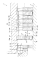
図1の蒸気タービンの一部を拡大して模式的に示す断面図である。
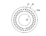
図1の蒸気タービンに使用される絞り体の一例を示す正面図である。
以下、本発明に係る実施形態を図面に従って説明するが、本発明はこの実施形態に限定されるものではない。
図1に、本発明の一実施形態に係る蒸気タービン1を示す。蒸気タービン1では、この蒸気タービン1の外部のボイラのような蒸気源から供給された蒸気Wによって蒸気タービン1の回転軸3が駆動され、回転軸3によって出力される回転動力によって発電機Gのような負荷5を駆動する。
蒸気タービン1は、静翼11および動翼13からなる段落STを複数備えている。各段落STは、タービンケーシング17の内周面に、周方向に複数設けられた静翼11と、回転軸3の外周面に、周方向に複数設けられた動翼13とからなる。タービンケーシング17の内側の空間が蒸気通路15を形成している。各段落STにおいて、静翼11の下流側に動翼13が配置されている。複数の段落STは、上流側から下流側へ向かうに従って次第に拡径しており、各段落STを経るに従って蒸気Wが膨張し、圧力が低下していく。
図示の例では、蒸気通路15に蒸気Wを取り入れる蒸気導入通路25に、蒸気通路15に流入する蒸気量を調整する蒸気加減弁27が設けられている。蒸気加減弁27の下流側の蒸気通路入口29に、第1段落STの静翼11が配置されている。最下流段落ST(図示の例では第9段落ST)の段落出口に、蒸気通路15から蒸気Wを排出する蒸気排出通路31が接続されている。蒸気W排出通路31から排出された蒸気Wは、図示しない復水器へ送られた後、蒸気源へ戻される。
図2に示すように、第2段落以降の静翼11は、その径方向外側の外周リング部11aと、径方向内側の内周リング部11bと、外周リング部11aと内周リング部11bとの間に設けられた複数の羽根からなるノズル部11cとを有している。静翼11の外周リング部11aがタービンケーシング17に連結されている。静翼11の径方向内側の内周リング部11bの内周面と、回転軸3の外周面との間にはラビリンスシール33が形成されている。動翼13は、その径方向外側のシュラウド部13aと、径方向内側の回転軸3から突設されたディスク部13bと、シュラウド部13aとディスク部13bとの間に設けられた複数の羽根からなる翼部13cとを有している。
本実施形態では、蒸気通路15において、少なくとも1つ(図示の例では1つ)の段落STの上流側に、通路面積を絞る絞り体35が設けられている。絞り体35は、その下流側の段落ST(つまりこの段落STの静翼11)から、当該段落の動翼13の軸方向幅以上の間隔で軸方向に離間して設けられている。なお、絞り体35は複数設けられていてもよい。
蒸気通路15に絞り体35を設けたことにより、絞り体35の下流側において蒸気Wの圧力が低下する。本実施形態では、絞り体35からその下流側の段落STまで上記の軸方向間隔Dを有する空間Sを設けているので、絞り体35から流出した蒸気Wが整流される。絞り体35の下流側の空間Sの軸方向間隔Dを、動翼寸法を基準として設定するので、従来の蒸気通路構造を利用することが容易となる。このようにして絞り体35により蒸気Wの圧力が低下する一方、蒸気Wは仕事をしないので、蒸気Wの温度は(後述するように瞬間的に低下するものの)動翼13を通過する場合ほど大幅には低下しない。したがって、絞り体35の下流側の空間Sにおいて蒸気Wの過熱度が回復するので、蒸気Wの湿り度が抑制される。さらには、限界湿り度におけるエンタルピー差が大きくなることから、蒸気タービン1の出力が向上するという効果も得られる。
なお、同図に示すように、絞り体35は、その上流側の段落ST(つまりこの段落STの動翼13)からも、当該段落の動翼13の軸方向幅以上の間隔で軸方向に離間して設けられていることが好ましい。もっとも絞り体35の上流側にこのような間隔を空けることは必須ではない。
図3に示すように、本実施形態に係る絞り体35は、多数の孔(以下、「絞り孔」と呼ぶ。)37を有する環状板である。この例では、環状板である絞り体35は、図2に示す静翼11と互換性のある構造を有している。より具体的には、絞り体35の径方向外側の外周部35aがタービンケーシング17に連結されている。また、絞り体35の内周面と回転軸3の外周面との間にラビリンスシール39が形成されている。
絞り体35の形態は、蒸気通路Pの通路面積を、軸心方向において局所的に絞ることが可能な構造を有していれば、図示の例に限定されない。例えば、タービンケーシング17に、回転軸3の外径よりも大きい内径を有する単なる(絞り孔37が形成されていない)環状板を取り付けて絞り体35として使用してもよい。もっとも、静翼11と互換性のある構造を有する環状板を絞り体35として使用することによって、従来の蒸気タービン構造を維持することが容易となる。さらに、図3に示したように、絞り体35を絞り孔37を有する環状板とすることにより、絞り孔37の数や大きさを変更することで容易に圧力低下の度合いを調整することができる。
また、図2に示すように、上記の環状板である絞り体35において、絞り体35の蒸気出口(この例では各絞り孔37)は、その下流側の静翼11のノズル部(羽根)11cの径方向位置からずれた径方向位置に形成されている。図示の例では、絞り体35の蒸気出口である各絞り孔37は、その下流側に位置する静翼11のノズル部11cの内径側端よりも内径側(この例では内周リング部11bが存在する径方向範囲)に位置している。
蒸気Wが絞り体35を通過する時、上述したように大幅な温度低下は起こらないものの、熱エネルギーが速度エネルギーに変わるため、蒸気Wの温度は瞬間的に低下する。蒸気Wが絞り体35を通過した直後、速度が低下せず直接ノズル部11cに流入した場合は、温度(すなわち過熱度)がさほど回復していない状態の蒸気Wがノズル部11cを通過することになる。これに対して、図示の例では、蒸気出口(絞り孔37)の径方向位置が、その下流側のノズル部11cの径方向位置とずれているので、絞り体35を通過した蒸気Wは、いったん内周リング部11bに衝突するなどして速度が低下し、十分に温度が回復した状態でノズル部11cを通過する。これにより、一層確実に蒸気Wの湿り度を抑制することができる。なお、絞り体35が絞り孔を有する環状板以外の形態である場合にも、蒸気出口が、その下流側の静翼11のノズル部(羽根)11cの径方向位置からずれた径方向位置に形成されていることが好ましい。もっとも、絞り体35において蒸気出口を形成する位置はこの例に限定されない。
絞り体35が設けられる位置は、図1の例に限定されない。もっとも、絞り体35は、できるだけ高圧側(上流側)に設けられることが好ましく、少なくとも、蒸気Wの過熱度が所定値以下となる段落よりも上流側に設けられることが好ましい。例えば、絞り体35は、複数の段落STのうち高圧側半分のいずれかの段落STの上流側に位置していることが好ましい。すなわち、図示の例では、絞り体35が、全9段落STのうちの、第1段落ST~第4段落STのいずれかの段落の上流側に配置されていることが好ましい。上記過熱度の「所定値」とは、例えば、10℃である。このように、絞り体35を高圧側の段落STの近傍に配置することにより、湿り度が低い状態の蒸気Wの圧力を低下させて、蒸気Wの湿り度を効果的に抑制することができる。
以上説明した本実施形態に係る蒸気タービン1によれば、供給される蒸気Wの温度が低い場合でも、絞り体35を設けて積極的に圧力を低下させることにより、蒸気Wの湿り度を抑制することができる。さらに、絞り体35の下流に動翼寸法を基準とした所定の広い空間Sを形成することにより、従来構造を利用しながら、絞り体35を通過した蒸気Wを整流することが可能になる。
以上のとおり、図面を参照しながら本発明の好適な実施形態を説明したが、本発明の趣旨を逸脱しない範囲内で、種々の追加、変更または削除が可能である。したがって、そのようなものも本発明の範囲内に含まれる。
1 蒸気タービン
3 回転軸
11 静翼
13 動翼
15 蒸気通路
35 絞り体
37 絞り孔(絞り体の蒸気出口)
39 ラビリンスシール
ST 段落
W 蒸気
3 回転軸
11 静翼
13 動翼
15 蒸気通路
35 絞り体
37 絞り孔(絞り体の蒸気出口)
39 ラビリンスシール
ST 段落
W 蒸気
Claims (6)
- 静翼および動翼からなる段落を複数備える蒸気タービンであって、
少なくとも1つの前記段落の上流に、前記動翼の軸方向幅以上の間隔で軸方向に離間して設けられた、蒸気通路の通路面積を絞る絞り体
を備える蒸気タービン。 - 請求項1に記載の蒸気タービンにおいて、前記絞り体が、蒸気の過熱度が所定値以下となる段落よりも上流側に設けられている蒸気タービン。
- 請求項2に記載の蒸気タービンにおいて、複数の前記段落のうち高圧側半分のいずれかの段落の上流側に前記絞り体が設けられている蒸気タービン。
- 請求項1から3のいずれか一項に記載の蒸気タービンにおいて、前記絞り体が、多数の孔を有する環状板である蒸気タービン。
- 請求項1から4のいずれか一項に記載の蒸気タービンにおいて、前記絞り体の蒸気出口が、その下流側の静翼の羽根の径方向位置からずれた径方向位置に形成されている蒸気タービン。
- 請求項4または請求項4を引用する請求項5に記載の蒸気タービンにおいて、前記絞り体の内周面と当該蒸気タービンの回転軸との間にラビリンスシールが形成されている蒸気タービン。
Priority Applications (2)
| Application Number | Priority Date | Filing Date | Title |
|---|---|---|---|
| JP2019561504A JP6970756B2 (ja) | 2017-12-27 | 2017-12-27 | 蒸気タービン |
| PCT/JP2017/047096 WO2019130517A1 (ja) | 2017-12-27 | 2017-12-27 | 蒸気タービン |
Applications Claiming Priority (1)
| Application Number | Priority Date | Filing Date | Title |
|---|---|---|---|
| PCT/JP2017/047096 WO2019130517A1 (ja) | 2017-12-27 | 2017-12-27 | 蒸気タービン |
Publications (1)
| Publication Number | Publication Date |
|---|---|
| WO2019130517A1 true WO2019130517A1 (ja) | 2019-07-04 |
Family
ID=67063455
Family Applications (1)
| Application Number | Title | Priority Date | Filing Date |
|---|---|---|---|
| PCT/JP2017/047096 Ceased WO2019130517A1 (ja) | 2017-12-27 | 2017-12-27 | 蒸気タービン |
Country Status (2)
| Country | Link |
|---|---|
| JP (1) | JP6970756B2 (ja) |
| WO (1) | WO2019130517A1 (ja) |
Citations (4)
| Publication number | Priority date | Publication date | Assignee | Title |
|---|---|---|---|---|
| JPS58202306A (ja) * | 1982-05-19 | 1983-11-25 | Toshiba Corp | 混圧式タ−ビン |
| JPS591802U (ja) * | 1978-05-24 | 1984-01-07 | キヤリア・コ−ポレイシヨン | 封止装置 |
| JPS6139404U (ja) * | 1984-08-14 | 1986-03-12 | 株式会社東芝 | 蒸気タ−ビン |
| JP2016011626A (ja) * | 2014-06-27 | 2016-01-21 | 三菱日立パワーシステムズ株式会社 | 静翼ユニット及び蒸気タービン |
Family Cites Families (1)
| Publication number | Priority date | Publication date | Assignee | Title |
|---|---|---|---|---|
| JP2002309906A (ja) * | 2001-04-11 | 2002-10-23 | Mitsubishi Heavy Ind Ltd | 蒸気冷却型ガスタービン |
-
2017
- 2017-12-27 WO PCT/JP2017/047096 patent/WO2019130517A1/ja not_active Ceased
- 2017-12-27 JP JP2019561504A patent/JP6970756B2/ja active Active
Patent Citations (4)
| Publication number | Priority date | Publication date | Assignee | Title |
|---|---|---|---|---|
| JPS591802U (ja) * | 1978-05-24 | 1984-01-07 | キヤリア・コ−ポレイシヨン | 封止装置 |
| JPS58202306A (ja) * | 1982-05-19 | 1983-11-25 | Toshiba Corp | 混圧式タ−ビン |
| JPS6139404U (ja) * | 1984-08-14 | 1986-03-12 | 株式会社東芝 | 蒸気タ−ビン |
| JP2016011626A (ja) * | 2014-06-27 | 2016-01-21 | 三菱日立パワーシステムズ株式会社 | 静翼ユニット及び蒸気タービン |
Also Published As
| Publication number | Publication date |
|---|---|
| JPWO2019130517A1 (ja) | 2021-01-07 |
| JP6970756B2 (ja) | 2021-11-24 |
Similar Documents
| Publication | Publication Date | Title |
|---|---|---|
| US20120121411A1 (en) | Labyrinth Seals for Turbomachinery | |
| US20140212269A1 (en) | Cooling for a fluid flow machine | |
| JP2016041934A (ja) | 多段軸流圧縮機装置 | |
| JP2011247257A5 (ja) | ||
| US10837290B2 (en) | Structure for cooling rotor of turbomachine, rotor and turbomachine having the same | |
| EP3553276B1 (en) | Gas turbine engine rotor with coolant flow redirection component | |
| JP6278329B2 (ja) | 蒸気タービン | |
| US11015449B2 (en) | Steam turbine blade and steam turbine | |
| EP3012409B1 (en) | Turbine assembly | |
| JP7187464B2 (ja) | タービンの先端バランススリット | |
| JP2012072708A (ja) | ガスタービンおよびガスタービンの冷却方法 | |
| JP2017057838A (ja) | ガスタービン冷却構造およびガスタービン | |
| JP2009036118A (ja) | 軸流排気型タービン | |
| JP5653486B2 (ja) | 軸流タービン用の固定ベーンアッセンブリ | |
| US20150167488A1 (en) | Adjustable clearance control system for airfoil tip in gas turbine engine | |
| JP6791777B2 (ja) | 地熱タービン | |
| WO2015198853A1 (ja) | 静翼ユニット及び蒸気タービン | |
| JP6970756B2 (ja) | 蒸気タービン | |
| JP2018040282A (ja) | 軸流タービン及びそのダイヤフラム外輪 | |
| WO2018155189A1 (ja) | 回転機械、回転機械の排気部材 | |
| JP6005861B2 (ja) | 低圧タービン | |
| JP2018035676A (ja) | タービン | |
| US20150020527A1 (en) | Steam turbomachine having a bypass circuit for throttle flow capacity adjustment | |
| US20140037439A1 (en) | Turbomachine exhaust diffuser | |
| JP2015178832A (ja) | 冷却孔入口を備えるロータ軸 |
Legal Events
| Date | Code | Title | Description |
|---|---|---|---|
| 121 | Ep: the epo has been informed by wipo that ep was designated in this application |
Ref document number: 17935922 Country of ref document: EP Kind code of ref document: A1 |
|
| ENP | Entry into the national phase |
Ref document number: 2019561504 Country of ref document: JP Kind code of ref document: A |
|
| NENP | Non-entry into the national phase |
Ref country code: DE |
|
| 122 | Ep: pct application non-entry in european phase |
Ref document number: 17935922 Country of ref document: EP Kind code of ref document: A1 |