WO2019130491A1 - 照明装置およびその診断方法 - Google Patents
照明装置およびその診断方法 Download PDFInfo
- Publication number
- WO2019130491A1 WO2019130491A1 PCT/JP2017/047006 JP2017047006W WO2019130491A1 WO 2019130491 A1 WO2019130491 A1 WO 2019130491A1 JP 2017047006 W JP2017047006 W JP 2017047006W WO 2019130491 A1 WO2019130491 A1 WO 2019130491A1
- Authority
- WO
- WIPO (PCT)
- Prior art keywords
- impact
- test
- lighting device
- shock
- mover
- Prior art date
- Legal status (The legal status is an assumption and is not a legal conclusion. Google has not performed a legal analysis and makes no representation as to the accuracy of the status listed.)
- Ceased
Links
- 0 C*CC(CC1)CC1=* Chemical compound C*CC(CC1)CC1=* 0.000 description 1
Images






Classifications
-
- A—HUMAN NECESSITIES
- A61—MEDICAL OR VETERINARY SCIENCE; HYGIENE
- A61B—DIAGNOSIS; SURGERY; IDENTIFICATION
- A61B1/00—Instruments for performing medical examinations of the interior of cavities or tubes of the body by visual or photographical inspection, e.g. endoscopes; Illuminating arrangements therefor
- A61B1/06—Instruments for performing medical examinations of the interior of cavities or tubes of the body by visual or photographical inspection, e.g. endoscopes; Illuminating arrangements therefor with illuminating arrangements
- A61B1/0655—Control therefor
-
- A—HUMAN NECESSITIES
- A61—MEDICAL OR VETERINARY SCIENCE; HYGIENE
- A61B—DIAGNOSIS; SURGERY; IDENTIFICATION
- A61B1/00—Instruments for performing medical examinations of the interior of cavities or tubes of the body by visual or photographical inspection, e.g. endoscopes; Illuminating arrangements therefor
-
- A—HUMAN NECESSITIES
- A61—MEDICAL OR VETERINARY SCIENCE; HYGIENE
- A61B—DIAGNOSIS; SURGERY; IDENTIFICATION
- A61B1/00—Instruments for performing medical examinations of the interior of cavities or tubes of the body by visual or photographical inspection, e.g. endoscopes; Illuminating arrangements therefor
- A61B1/06—Instruments for performing medical examinations of the interior of cavities or tubes of the body by visual or photographical inspection, e.g. endoscopes; Illuminating arrangements therefor with illuminating arrangements
-
- F—MECHANICAL ENGINEERING; LIGHTING; HEATING; WEAPONS; BLASTING
- F21—LIGHTING
- F21S—NON-PORTABLE LIGHTING DEVICES; SYSTEMS THEREOF; VEHICLE LIGHTING DEVICES SPECIALLY ADAPTED FOR VEHICLE EXTERIORS
- F21S2/00—Systems of lighting devices, not provided for in main groups F21S4/00 - F21S10/00 or F21S19/00, e.g. of modular construction
-
- F—MECHANICAL ENGINEERING; LIGHTING; HEATING; WEAPONS; BLASTING
- F21—LIGHTING
- F21V—FUNCTIONAL FEATURES OR DETAILS OF LIGHTING DEVICES OR SYSTEMS THEREOF; STRUCTURAL COMBINATIONS OF LIGHTING DEVICES WITH OTHER ARTICLES, NOT OTHERWISE PROVIDED FOR
- F21V23/00—Arrangement of electric circuit elements in or on lighting devices
Definitions
- the present invention relates to a lighting device.
- Japanese Patent No. 4732783 is directed to a light guide, a phosphor disposed on the front end side of the light guide, a semiconductor laser light source for emitting excitation light for exciting the phosphor, and excitation light to the rear end of the light guide
- An endoscope illumination device includes a condensing lens for condensing light.
- the document also discloses an endoscope system having an endoscope incorporating an endoscope illumination device.
- An object of the present invention is to provide a lighting device and a diagnostic method for efficiently performing a diagnostic test for diagnosing the presence or absence of a failure.
- the illumination device comprises an illumination system for emitting illumination light, an impact sensor for detecting an impact, a memory for storing information of an impact detected by the impact sensor, and information on an impact stored in the memory. And a light source controller for performing a diagnostic test for diagnosing the presence or absence of a failure of the illumination system.
- the diagnostic method according to the present invention is a diagnostic method of an illumination device having an illumination system for emitting illumination light, an impact sensor for detecting an impact, and a memory for storing information of the impact detected by the impact sensor. Based on the information of the impact stored in the memory, a diagnostic test is performed to diagnose the presence or absence of a failure of the illumination system.
- a lighting device and a diagnostic method for efficiently performing a diagnostic test for diagnosing the presence or absence of a failure are provided.
- FIG. 1 shows an endoscope system according to an embodiment.
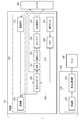
- FIG. 2 shows functional blocks of the endoscope system shown in FIG.
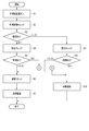
- FIG. 3 shows a flowchart of processing of the activation of the endoscope system and the accompanying illumination device.
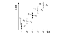
- FIG. 4 is a graph showing the measurement results of a test item for measuring the brightness of the illumination light emitted from the optical system with respect to the current supplied to the light source, which is performed in the diagnosis in the full test mode.
- FIG. 5 is a graph showing the measurement results of the test item for measuring the luminance of the illumination light emitted from the optical system with respect to the current supplied to the light source, which is performed in the diagnosis in the simplified test mode.
- FIG. 4 is a graph showing the measurement results of a test item for measuring the brightness of the illumination light emitted from the optical system with respect to the current supplied to the light source, which is performed in the diagnosis in the full test mode.
- FIG. 5 is a graph showing the measurement results of the test item for measuring the luminance of the
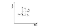
- FIG. 6 is a graph showing the measurement results of test items for measuring the luminance of the illumination light emitted from the optical system with respect to the current supplied to the light source in another simplified test mode.
- FIG. 7 is a graph showing another measurement result of the test item for measuring the luminance of the illumination light emitted from the optical system with respect to the current supplied to the light source in the same simplified test mode as FIG.
- FIG. 8 shows a composite shock sensor having the function of shock sensor and the function of memory.
- FIG. 9 is an exploded view of the shock sensing element shown in FIG.
- FIG. 10 shows a cross section of the shock sensing element shown in FIG. 8 before and after receiving a shock.
- FIG. 11 shows another shock sensing element having a shock sensor function and a memory function.
- FIG. 12 shows the elastic member and the mover shown in FIG. 11 before and after receiving an impact.
- FIG. 13 schematically shows still another shock sensing element having a shock sensor function and a memory function.
- FIG. 14 schematically shows an impact sensing element according to a modification of the impact sensing element shown in FIG.
- FIG. 15 is a perspective view of an impact sensing unit of the impact sensing element shown in FIG.
- FIG. 16 schematically shows the impact sensing unit shown in FIG. 15 which has received an impact in the lateral direction.
- FIG. 17 schematically shows the shock sensing unit shown in FIG. 15 which has been shocked along the vertical axis.
- FIG. 18 schematically shows an impact sensing element according to a modification of the impact sensing element shown in FIG.
- FIG. 19 schematically shows the impact sensing unit shown in FIG. 18 which has been laterally impacted.
- FIG. 20 schematically shows the shock sensing unit shown in FIG. 18 which has been shocked along the vertical axis.
- FIG. 1 shows an endoscope system 100 according to an embodiment.
- the endoscope system 100 displays an endoscope 110 configured to capture an observation target, a control device 160 configured to process an image captured by the endoscope 110, and the like, and an image captured by the endoscope 110. It has a monitor 180.
- the endoscope 110 is configured of a wireless endoscope, and transmission and reception of signals between the endoscope 110 and the control device 160 are performed wirelessly.
- the endoscope 110 has a hollow elongated insertion portion 130 inserted into a space such as a lumen or a conduit of an observation object, and an operation portion 120 connected to the proximal end side of the insertion portion 130 There is.
- the insertion portion 130 includes a distal end hard portion 132 located at the distal end, a curved portion 134 coupled to the proximal end side of the distal end hard portion 132, and a flexible tube portion 136 coupled to the proximal end side of the curved portion 134.
- the bending portion 134 is configured to be bendable in a desired direction by operating the operation portion 120.
- the flexible tube portion 136 is bendable, and can be bent, for example, in accordance with the shape of a lumen, a conduit or the like of the object to be observed.
- the operation unit 120 has an operation dial 122 for bending the bending portion 134.
- the operation unit 120 is mounted with a battery 124 for supplying electric power to electric components inside the endoscope 110 (for example, the illumination device 200, the imaging device 272, and the transmitter 274 described later).
- the battery 124 is removed from the operation unit 120 while the endoscope 110 is not in use, and is attached to the operation unit 120 at the next use. Thus, power is not supplied to the endoscope 110 while the endoscope 110 is not in use.
- the wireless endoscope 110 is convenient because it has no universal cord and can change the posture and position of the endoscope 110 without being pulled by the universal cord.
- FIG. 2 shows functional blocks of the endoscope system 100 shown in FIG. As shown in FIG. 2, the endoscope system 100 includes the endoscope 110, the control device 160, and the monitor 180 as described above.
- the endoscope 110 incorporates the illumination device 200.
- the illumination device 200 includes an illumination system 210 for illuminating an observation object.
- the illumination system 210 includes a light source 212, a coupling lens 214, an optical fiber 216 which is a light guide member, and a light conversion element 218 which converts incident light into illumination light.
- the light source 212 and the coupling lens 214 are disposed inside the operation unit 120.
- An optical fiber 216 extends through the insert 130.
- the light conversion element 218 is disposed inside the distal end hard portion 132 of the insertion portion 130.
- the light source 212 is not limited to this, in the present embodiment, it is configured by a laser light source, for example, a laser diode.
- Coupling lens 214 couples the light emitted from light source 212 to optical fiber 216.
- the optical fiber 216 guides the incident light to the light conversion element 218.
- the light conversion element 218 converts the light incident from the optical fiber 216 into illumination light having a desired quality.
- the illumination light having the desired quality is preferably light having a broad light distribution and an almost constant intensity distribution.
- the light conversion element 218 is configured of, for example, a diffuser that diffuses incident light.
- the light conversion element 218 may also be configured of a phosphor that absorbs incident light and emits light of a wavelength different from the wavelength of the incident light.
- the endoscope system 100 includes an imaging system 270 for imaging an observation target.
- the imaging system 270 includes an imaging element 272 that receives light from an observation target and outputs an image signal of an optical image of the observation target, and a transmitter 274 that wirelessly transmits an image signal output from the imaging element 272.
- the imaging element 272 is disposed inside the distal end rigid portion 132 of the insertion portion 130.
- the transmitter 274 is disposed inside the operation unit 120.
- the receiver 276 and the image processing circuit 278 are disposed inside the control device 160.
- the image processing circuit 278 is disposed inside the control device 160, but a part of the image processing circuit 278 may be disposed inside the endoscope 110.
- the operator After use of the endoscope 110 until the next use, for example, at the time of non-use such as cleaning of the endoscope 110, the operator mishandles and drops the endoscope 110 to the floor If the endoscope 110 receives an impact due to a collision or collision with another object, the illumination system 210 of the illumination device 200 may be damaged. When the optical fiber 216 and the light conversion element 218 of the illumination system 210 are damaged, a defect such as failure to emit illumination light having a desired quality may occur at the next use.
- the illumination device 200 diagnoses the presence or absence of a failure of the illumination system 210 when the endoscope system 100 is activated, and that the illumination system 210 is not damaged. After confirming, it is configured to drive. If the operator accidentally removes the hand from the endoscope, the wireless endoscope without the universal cord may fall to the ground as it is. Therefore, it is more important to drive the wireless endoscope after confirming that the illumination system is not damaged.
- the illumination device 200 further detects an impact received by the endoscope 110 while the endoscope 110 is not in use, in other words, while the illumination device 200 is not driven, and based on the detection result, It is configured to change the content of a diagnostic test that diagnoses the presence or absence of a failure of the illumination system 210.
- the lighting device 200 while the lighting device 200 is not driven, it may be rephrased as a state where there is no power supply to the lighting device 200.
- the lighting device 200 includes an impact sensor 222 that detects an impact, and a memory 224 that stores the impact detected by the impact sensor 222.
- the impact sensor 222 and the memory 224 are configured to be used repeatedly.
- the impact sensor 222 and the memory 224 do not include a mode in which an impact is detected or information is stored due to breakage of a member, such as wire breakage, for example.
- the impact sensor 222 is configured to detect an impact while the lighting device 200 is not driven, in other words, while the lighting device 200 is not receiving power.
- the impact sensor 222 may be configured to detect an impact while the lighting device 200 is driven.
- the impact sensor 222 is disposed, for example, near the light conversion element 218.
- the light conversion element 218 is broken or dropped, the laser light emitted from the optical fiber 216 is not properly converted by the light conversion element 218.
- the light conversion element 218 is a diffuser, diffusion Laser light that is not sufficiently diffused by the body and thus deviates from the desired quality may be emitted from the tip of the insertion portion 130 of the endoscope 110. That is, the light conversion element 218 is an important optical component for the emission of illumination light having a desired quality. Therefore, the vicinity of the light conversion element 218 is one of the candidates considered to be suitable as a placement place of the impact sensor 222.
- the impact sensor 222 is disposed, for example, near the optical fiber 216.
- the optical fiber 216 When the optical fiber 216 is broken, the laser light emitted from the optical fiber 216 may not be properly guided, and in some cases, may be emitted from the tip of the insertion portion 130 of the endoscope 110.
- the optical fiber 216 is also an important optical component for the emission of illumination light having the desired quality. Therefore, the vicinity of the optical fiber 216 is also one of the candidates considered appropriate as the placement location of the impact sensor 222.
- the impact sensor 222 is disposed, for example, inside the distal end rigid portion 132.
- the distal end hard portion 132 is also a portion that is considered to often collide with the floor or other objects when the endoscope 110 is not used, and is a portion that is considered to be susceptible to a strong impact when colliding. . Therefore, the inside of the distal end hard portion 132 is also one of the candidates considered to be suitable as the placement point of the impact sensor 222.
- the impact sensor 222 is disposed, for example, inside the operation unit 120.
- the operation unit 120 is a portion considered to be susceptible to a strong impact when the endoscope 110 falls to the floor. Therefore, the inside of the operation unit 120 is also one of the candidates considered to be suitable as the placement location of the impact sensor 222.
- the impact sensor 222 may be disposed not only at the point described here, but also near other optical components that are important for the emission of laser light of safe intensity or at other points considered to be susceptible to strong impact .
- the lighting device 200 may have only one impact sensor 222 or may have a plurality of impact sensors 222.
- the plurality of impact sensors 222 may be located at the locations described herein and / or elsewhere.
- the impact sensor 222 is configured of, for example, a single impact sensing element.
- a single impact sensing element is configured to detect impacts along, for example, multiple axes, eg, three axes.
- the impact sensor 222 may be composed of a complex of a plurality of impact sensing elements. Each impact sensing element is configured to detect an impact along one axis, for example. In this case, the impact sensor 222 may include three impact sensing elements that detect impacts along different axes. Alternatively, each impact sensing element may be configured to detect an impact in one direction. In this case, the impact sensor 222 preferably includes six impact sensing elements that detect impacts in different directions.
- the impact sensor 222 may have, for example, a plurality of impact sensing elements having different sensitivities.
- the memory 224 includes a plurality of storage elements each storing an impact detected by the plurality of impact sensing elements.
- the impact sensor 222 and the memory 224 are both configured by mechanical elements.
- a mechanical element means an element that functions without using electricity. That is, the impact sensor 222 and the memory 224 are configured to function without using electricity. That is, the impact sensor 222 is configured by a mechanical sensor.
- the memory 224 is configured by a mechanical memory.
- the impact sensor 222 is configured to detect an impact exceeding a predetermined magnitude.
- memory 224 is configured to store a history of shocks detected by shock sensor 222.
- the impact sensor 222 and the memory 224 are integrally configured, for example. In other words, the impact sensor 222 and the memory 224 are configured by a single mechanical element. Specific examples of such mechanical elements will be described later with reference to FIGS. 8 to 12.
- the impact sensor 222 may be configured by a mechanical element
- the memory 224 may be configured by an electrical element.
- an electrical element means an element that functions using electricity. The specific example will be described later with reference to FIGS. 13 to 20.
- the lighting device 200 also includes a light source controller 226 that controls the light source 212.
- the light source controller 226 may be configured by, for example, a microcomputer, an integrated circuit, or the like that operates in accordance with pre-programmed software.
- the light source controller 226 is configured to control the light source 212 according to various drive modes.
- the drive mode includes, for example, a normal mode for emitting illumination light for observation of an observation object by the endoscope system 100 and a diagnostic test for diagnosing the presence or absence of a failure of the illumination system 210 at startup of the endoscope system 100. Includes a diagnostic mode that emits illumination light for.
- the light source controller 226 may, for example, the light source 212 such that illumination light for a diagnostic test is emitted from the light source 212 which is weaker than the light emitted from the light source 212 in the normal mode, for safety, in diagnostic mode. Control.
- the diagnostic mode includes a plurality of test modes in accordance with test items to be performed or omitted in the diagnostic test with respect to a plurality of test items prepared for the diagnostic test.
- the plurality of test modes are divided into a complete test mode in which all the test items are performed and a non-complete test mode different from the full test mode with respect to a plurality of test items prepared for a diagnostic test.
- the diagnostic test in the incomplete test mode can be performed in a short time as compared with the diagnostic test in the complete test mode.
- the implementation of at least one test item in the plurality of test items is omitted, and the simplified test mode in which the remaining test items in the plurality of test items are implemented, and the plurality of test items are implemented. Not including the test omission mode.
- the simplified test mode includes various modes depending on the test item whose implementation is omitted.
- the light source controller 226 selects one test mode from a plurality of test modes based on the shock information stored in the memory 224, and drives the light source 212 according to the selected test mode. Is configured.
- the light source controller 226 is also configured to diagnose the presence or absence of a failure of the illumination system 210 based on the image signal output from the imaging device 272 in the diagnostic mode.
- the shutter 242 is provided at the tip of the insertion portion 130 of the endoscope 110 so that the illumination light emitted from the illumination system 210 is incident on the imaging element 272 after being reflected by the shutter 242.
- the shutter 242 is configured of, for example, a white balance cap.
- the shutter 242 may be composed of any member as long as it has an appropriate reflectance.
- FIG. 3 shows a flowchart of activation of the endoscope system 100 and processing in the illumination device 200 accordingly. The process of FIG. 3 is performed mainly by the light source controller 226.
- the illumination device 200 shifts to drive of the light source 212 in the normal mode or the illumination system 210 It represents the time until the notification of a failure.
- step S1 after the endoscope system 100 is activated, in step S2, the light source controller 226 checks the information on the impact stored in the memory 224.
- the impact sensor 222 is configured to detect an impact exceeding a predetermined magnitude, and the memory 224 stores the history of the impact detected by the impact sensor 222 (the fact that the impact is detected). Is configured.
- the shock information stored in the memory 224 is a history of shocks detected by the shock sensor 222.
- step S3 the light source controller 226 determines whether the shock history stored in the memory 224 indicates that the shock sensor 222 has detected a shock. If it is determined that the shock history indicates that the shock sensor 222 has detected a shock, the process proceeds to step S4. Conversely, if it is determined that the shock history indicates that the shock sensor 222 has not detected a shock, the process proceeds to step S8.
- step S4 the light source controller 226 selects the complete test mode and drives the light source 212 according to the complete test mode At the same time, based on the image signal output from the imaging element 272, the presence or absence of a failure of the illumination system 210 is diagnosed. Diagnosis in the complete test mode is conveniently referred to as a complete check.
- the light source controller 226 also notifies that it is performing a full test mode diagnosis while making a diagnosis. For example, the light source controller 226 causes the monitor 180 to display a message indicating that diagnosis in the complete test mode is being performed. Thereafter, the process proceeds to step S5.
- step S5 the light source controller 226 determines whether the illumination system 210 has a failure. If it is determined that there is no failure in the illumination system 210, the process proceeds to step S6. Conversely, if it is determined that the illumination system 210 has a failure, the process proceeds to step S10.
- step S5 If it is determined in step S5 that there is no failure in the illumination system 210, the light source controller 226 resets the impact information stored in the memory 224, for example, the history of the impact in step S6. Thereafter, the process proceeds to step S7.
- step S7 the light source controller 226 drives the light source 212 in the normal mode.
- step S8 the light source controller 226 selects the non-perfect test mode and follows the non-perfect test mode
- the light source 212 is driven, and the presence or absence of a failure of the illumination system 210 is diagnosed based on the image signal output from the imaging device 272.
- the light source controller 226 selects the simplified test mode as the incomplete test mode and diagnoses the presence or absence of a failure of the illumination system 210.
- the diagnosis in the simple test mode is referred to as a simple check for the sake of convenience.
- the light source controller 226 also notifies that the diagnosis in the simple test mode is being performed while performing the diagnosis. For example, the light source controller 226 causes the monitor 180 to display a message indicating that diagnosis in the simple test mode is being performed. Thereafter, the process proceeds to step S9.
- step S9 the light source controller 226 determines whether the illumination system 210 has a failure. If it is determined that there is no failure in the illumination system 210, the process proceeds to step S7. Conversely, if it is determined that the illumination system 210 has a failure, the process proceeds to step S10.
- step S10 the light source controller 226 notifies the illumination system 210 that there is a failure. For example, the light source controller 226 causes the monitor 180 to display a message indicating that the illumination system 210 has a failure.
- FIG. 4 is a graph showing the measurement results of test items performed in diagnosis in the complete test mode.
- FIG. 5 is a graph showing measurement results of test items performed in diagnosis in the simple test mode.
- the horizontal axis represents the magnitude of the current supplied to the light source 212
- the vertical axis represents the intensity (brightness) of light emitted from the illumination system 210, and more specifically, it is emitted from the light conversion element 218.
- the intensity of light reflected by the shutter 242 and incident on the image sensor 272 is shown.
- the light source controller 226, first, supplying a current of a current value I 1 to the light source 212, based on the image signals output from the image sensor 272, a light intensity value P 1 with respect to the current value I 1 taking measurement.
- Light intensity value P 1 is, for example, be a sum of the output signals of the pixels of the image sensor 272.
- the light source controller 226 changes the magnitude of the current supplied to the light source 212 to the current value I 2, to measure the light intensity values P 2 with respect to the current value I 2.
- the light source controller 226 performs the supply of the current values I 3 , I 4 and I 5 and the measurement of the light intensity values P 3 , P 4 and P 5 .
- light intensity values P 1 to P 5 are obtained for each of the five current values I 1 to I 5 .
- the light source controller 226 causes the illumination system 210 to fail when all of the five light intensity values P 1 to P 5 for the five current values I 1 to I 5 fall within the respective standard ranges S 1 to S 5 . I will not judge.
- the light source controller 226 is an illumination system 210 when any one of the five light intensity values P 1 to P 5 for the five current values I 1 to I 5 is out of the respective standard ranges S 1 to S 5. Judge that there is a failure in
- the five light intensity values P 1 to P 5 correspond to the respective standard ranges S 1 to S.
- the illumination system 210 may be notified that there is a failure, and the measurement of the light intensity value for the remaining current value may be omitted. . By doing this, it is possible to shorten the time required for the diagnostic test when there is a failure in the illumination system 210.
- the light source controller 226 supplies a current of a current value I 5 to the light source 212, based on the image signals output from the image sensor 272, the light intensity values P 5 with respect to the current value I 5 taking measurement.
- the light intensity value P 5 obtained for one of the current values I 5.
- the light intensity values P 5 for the highest current value I 5 are measured, the current value (check point) is not limited thereto. Light intensity values for any of the other current values I 1 to I 4 may be measured.
- the measurement of the light intensity value for one current value and the determination of the presence or absence of a failure of the illumination system 210 based on the measured light intensity value are taken as one test item.
- the complete test mode five test items are performed, and in the simple test mode, one test item is performed.
- the endoscope 110 receives an impact exceeding a predetermined size, and thus there is a risk that the illumination system 210 may have a failure.
- the diagnostic test is performed in the complete test mode in which all test items are performed, in other words, the diagnostic test is performed carefully to check the presence or absence of a failure of the illumination system 210, and conversely, the endoscope 110 has a predetermined size.
- the diagnostic test by the simplified test mode in which at least one test item is omitted and the test item is performed, in other words, the test item is not conducted if there is substantially no possibility that the lighting system 210 has a failure.
- a diagnostic test with a short required time, or a diagnostic test in a test omission mode in which no test item is performed at all, in other words, a diagnostic Omission of the strike itself is carried out.
- a diagnostic test for diagnosing the presence or absence of a failure of the illumination system 210 is efficiently performed. That is, if there is substantially no risk that the illumination system 210 has a failure while the endoscope 110 is not in use, the execution of at least one test item or the execution of all test items is omitted. Therefore, the time required for the diagnostic test can be shortened.
- the measurement of the light intensity (brightness) of the illumination light emitted from the light conversion element 218 with respect to the current supplied to the light source 212 described herein is only one example of the test item.
- the difference between the complete test mode and the simple test mode is not limited to the difference in the number of current values.
- the test items include, for example, ( ⁇ ) measurement of light intensity (brightness) of illumination light emitted from the light conversion element 218 with respect to current supplied to the light source 212, ( ⁇ ) color tone of illumination light emitted from the light conversion element 218 And ( ⁇ ) measurement of the luminance unevenness of the illumination light emitted from the light conversion element 218.
- the intensity (brightness) of the illumination light emitted from the light conversion element 218 with respect to the current supplied to the light source 212 is measured.
- the measurement of the luminance is performed based on the image signal output from the imaging element 272.
- the presence or absence of a failure of the illumination system 210 is determined based on whether or not the measured luminance falls within a predetermined luminance range (standard range).
- the color tone of the illumination light emitted from the light conversion element 218 is measured.
- the measurement of the color tone is performed based on the image signal output from the imaging element 272.
- the presence or absence of a failure of the illumination system 210 is determined based on whether or not the measured color tone falls within a predetermined color tone range.
- the luminance unevenness of the illumination light emitted from the light conversion element 218 is measured.
- the measurement of the uneven brightness is performed based on the image signal output from the image sensor 272.
- the presence or absence of a failure of the illumination system 210 is determined based on whether or not the measured luminance unevenness falls within a predetermined luminance unevenness range.
- the following shows an example of combination of test items performed in the complete test mode and test items performed in the simple test mode.
- test items ( ⁇ ) are performed for five current values.
- test item ( ⁇ ) is performed for one current value.
- Test items ( ⁇ ) for one current value are regarded as one test item. That is, in the complete test mode, five test items ( ⁇ ) are performed, and in the simple test mode, one test item ( ⁇ ) is performed.
- the number of test items ( ⁇ ) is merely an example, and the number of test items ( ⁇ ) in the complete test mode may be larger than the number of test items ( ⁇ ) in the simple test mode.
- test item ( ⁇ ) is performed in both the complete test mode and the simple test mode.
- the standard range in the complete test mode and the standard range in the simple test mode are different. Specifically, the standard range in the simple test mode is wider than the standard range in the complete test mode.
- test item ( ⁇ ) is performed, for example, for one current value.
- test item ( ⁇ ) may be performed for a plurality of current values.
- test item ( ⁇ ) and the test item ( ⁇ ) are sequentially performed.
- simple test mode only the test item ( ⁇ ) is performed.
- the test item ( ⁇ ) is performed, for example, for one current value in both the complete test mode and the simplified test mode.
- the test item ( ⁇ ) may be performed for a plurality of current values.
- the test item ( ⁇ ) may be performed for more current values than the current values in the simple test mode.
- test item ( ⁇ ) determines whether or not there is a failure in the illumination system 210 is made each time a test item is completed.
- test item ( ⁇ ) is completed, if it is determined that there is a failure in the lighting system, it is notified that the lighting system 210 has a failure without performing the remaining test items ( ⁇ ), and the diagnostic test is performed. Finish.
- test item ( ⁇ ) and the test item ( ⁇ ) are sequentially performed.
- the simplified test mode only the test item ( ⁇ ) is performed.
- test item ( ⁇ ) is performed, for example, for one current value.
- test item ( ⁇ ) may be performed for a plurality of current values.
- determination of whether or not there is a failure in the illumination system 210 is made each time a test item is completed.
- the test item ( ⁇ ) is completed, if it is determined that there is a failure in the illumination system, it is notified that there is a failure in the illumination system 210 without performing the test item ( ⁇ ), and the diagnostic test is ended. Do.
- test item ( ⁇ ) and the test item ( ⁇ ) are sequentially performed.
- a test item ( ⁇ ) is performed.
- test item ( ⁇ ) is performed, for example, for one current value.
- test item ( ⁇ ) may be performed for a plurality of current values.
- determination of whether or not there is a failure in the illumination system 210 is made each time a test item is completed.
- the test item ( ⁇ ) is completed, if it is determined that there is a failure in the illumination system, it is notified that there is a failure in the illumination system 210 without performing the test item ( ⁇ ), and the diagnostic test is ended. Do.
- test item ( ⁇ ) and the test item ( ⁇ ) are sequentially performed.
- the simplified test mode only the test item ( ⁇ ) is performed.
- test item ( ⁇ ) is performed, for example, for one current value.
- test item ( ⁇ ) may be performed for a plurality of current values.
- determination of whether or not there is a failure in the illumination system 210 is made each time a test item is completed.
- the test item ( ⁇ ) is completed, if it is determined that there is a failure in the lighting system, the lighting system 210 is notified that there is a failure without performing the test item ( ⁇ ), and the diagnostic test is ended. Do.
- Example 7 of diagnostic test test items The time required for the test item ( ⁇ ) is assumed to be shorter than the time required for the test item ( ⁇ ).
- test item ( ⁇ ) and the test item ( ⁇ ) are sequentially performed.
- simple test mode only one of the test item ( ⁇ ) and the test item ( ⁇ ) is performed.
- simplified test mode it is preferable to execute the test item ( ⁇ ) from the viewpoint of shortening the time required for the simplified check.
- test item ( ⁇ ) is performed, for example, for one current value.
- test item ( ⁇ ) may be performed for a plurality of current values.
- determination of whether or not there is a failure in the illumination system 210 is made each time a test item is completed.
- the test item ( ⁇ ) is completed, if it is determined that the lighting system 210 has a failure, the lighting system 210 is notified of the failure without performing the test item ( ⁇ ), and the diagnostic test is performed. finish. Thereby, when there is a failure in the illumination system 210, this can be notified earlier, and the diagnostic test can be completed more quickly.
- Example 8 of diagnostic test test items The time required for the test item ( ⁇ ) is assumed to be shorter than the time required for the test item ( ⁇ ).
- test item ( ⁇ ) and the test item ( ⁇ ) are sequentially performed.
- simple test mode only one of the test item ( ⁇ ) and the test item ( ⁇ ) is performed.
- simplified test mode it is preferable to execute the test item ( ⁇ ) from the viewpoint of shortening the time required for the simplified check.
- test item ( ⁇ ) is performed, for example, for one current value.
- test item ( ⁇ ) may be performed for a plurality of current values.
- determination of whether or not there is a failure in the illumination system 210 is made each time a test item is completed.
- the test item ( ⁇ ) is completed, if it is determined that there is a failure in the illumination system, it is notified that there is a failure in the illumination system 210 without performing the test item ( ⁇ ), and the diagnostic test is ended. Do. Thereby, when there is a failure in the illumination system 210, this can be notified earlier, and the diagnostic test can be completed more quickly.
- the impact sensor 222 has a high sensitivity first impact sensing element and a low sensitivity second impact sensing element.
- the memory 224 has a first storage element for storing an impact detected by the first impact sensing element, and a second storage element for storing an impact detected by the second impact sensing element.
- the simplified test mode has a first simplified test mode and a second simplified test mode.
- the light source controller 226 selects the test mode based on the information on the shock stored in the first storage element and the second storage element. For example, the light source controller 226 indicates that the shock information stored in the first storage element indicates that the first shock sensing element has detected a shock, and the shock stored in the second storage element. If the second information indicates that the second shock sensing element has detected a shock, the complete test mode is selected.
- the light source controller 226 indicates that the shock information stored in the first storage element indicates that the first shock sensing element has detected a shock, and the shock stored in the second storage element. If the second information indicates that the second impact sensing element did not detect an impact, the first simplified test mode is selected.
- the light source controller 226 indicates that the shock information stored in the first storage element indicates that the first shock sensing element did not detect a shock, and the light source controller 226 stores the information in the second storage element.
- the second simplified test mode is selected if the information of the impact that is present indicates that the second impact sensing element did not detect an impact.
- test items ( ⁇ ) are performed for five current values. In other words, in the complete test mode, the current value is changed to perform five test items ( ⁇ ).
- test items ( ⁇ ) are performed for three current values. In other words, in the first simplified test mode, the current value is changed to perform three test items ( ⁇ ).
- a test item ( ⁇ ) is performed for one current value. In other words, one test item ( ⁇ ) is performed in the second simplified test mode.
- the simplified test mode has a first simplified test mode and a second simplified test mode.
- the configurations of the impact sensor 222 and the memory 224 are the same as those of the ninth example.
- the way of selecting the first simplified test mode and the second simplified test mode is also the same as in the case of the ninth example.
- test item ( ⁇ ), the test item ( ⁇ ) and the test item ( ⁇ ) are sequentially performed.
- test item ( ⁇ ) and the test item ( ⁇ ) are sequentially performed.
- second simplified test mode only the test item ( ⁇ ) is performed.
- the required time of the test item ( ⁇ ) is shorter than the required time of the test item ( ⁇ ).
- the required time of the test item ( ⁇ ) is shorter than the required time of the test item ( ⁇ ). That is, in the complete test mode and the first simple test mode, test items with short required time are performed first, and test items with long required time are performed later.
- test item ( ⁇ ) is performed, for example, for one current value.
- test item ( ⁇ ) may be performed for a plurality of current values.
- the complete test mode when the test item ( ⁇ ) is completed, if it is determined that the illumination system has a failure, the illumination system 210 is performed without performing the remaining test items ( ⁇ ) and the test items ( ⁇ ). Informing that there is a fault in the and terminating the diagnostic test.
- the complete test mode and the first simple test mode when it is determined that there is a failure in the illumination system when the test item ( ⁇ ) is completed, the remaining test items ( ⁇ ) are not performed. The lighting system 210 is notified that there is a failure, and the diagnostic test is ended.
- test item ( ⁇ ) in the simplified test mode the presence or absence of a failure of the illumination system 210 is determined based on whether or not the measured luminance falls within a predetermined luminance range (standard range). It may be determined by comparing it to the luminance measured at the previous use of the mirror 110.
- a predetermined luminance range standard range
- FIG. 6 and 7 are graphs similar to FIG. 5, and in such a simple test mode, the test item ( ⁇ ) for measuring the luminance of the illumination light emitted from the illumination system 210 with respect to the current supplied to the light source 212 It is a graph shown.
- P p indicates the luminance value measured last time
- P n indicates the luminance value measured this time
- S a indicates the standard range for the luminance values P p and P n
- S b indicates the luminance value P p
- S c is the lowest standard range luminance value P p, for P n.
- the light source controller 226 stores the previously measured luminance value.
- the light source controller 226 supplies a current to the light source 212, and measures the luminance value P n with respect to the current value based on the image signal output from the imaging device 272.
- the light source controller 226 obtains a difference (P n ⁇ P p ) between the luminance value P n measured this time and the luminance value P p measured last time.
- the light source controller 226 compares the difference (P n ⁇ P p ) with the standard range S b .
- the difference (P n ⁇ P p ) is within the standard range S b .
- the light source controller 226 determines that the illumination system 210 has no failure.
- the difference (P n -P p ) is out of the standard range S b , the light source controller 226 determines that the illumination system 210 has a failure.
- the minimum specification range Sc is a specification range in which the brightness of the illumination light emitted from the illumination system 210 must at least satisfy.
- FIG. 8 shows a composite impact sensor 300 having the function of impact sensor 222 and the function of memory 224.
- FIG. 9 is an exploded view of the impact sensing element 310 shown in FIG.
- FIG. 10 shows a cross section of the shock sensing element 310 shown in FIG. 8 before and after receiving a shock.
- the composite impact sensor 300 has an impact sensing element 310 that senses and stores an impact in one direction.
- the impact sensing element 310 is composed of a mechanical element.
- the impact sensing element 310 has a stator 312 and a mover 314.
- the stator 312 and the mover 314 are both made of an insulator.
- the stator 312 is fixed to the endoscope 110 in a state in which the impact sensing element 310 is installed in the endoscope 110.
- the mover 314 is attached to the end of the stator 312.
- the end on which the mover 314 is mounted is referred to as a distal end, and the opposite end is referred to as a proximal end.
- the stator 312 is formed in a cylindrical shape
- the mover 314 is formed in a bottomed cylindrical shape.
- the mover 314 has a recess.
- the impact sensing element 310 having the stator 312 and the mover 314 has, for example, a diameter of about 100 ⁇ m and a length of about several mm.
- the shapes of the stator 312 and the mover 314 are merely an example, and the present invention is not limited thereto, and may have any other shape as long as it has the functions described herein. .
- the stator 312 and the mover 314 are formed to fit each other.
- the mover 314 is held by the stator 312 with an appropriate frictional resistance with respect to the stator 312, and fixed along the axis of the stator 312, more specifically, in the direction from the distal end to the proximal end. It is configured to move relative to the stator 312 when the child 312 receives an impact exceeding a predetermined magnitude.
- the stator 312 and the mover 314 are preferably configured to prevent the mover 314 from completely coming off the stator 312.
- the stator 312 and the mover 314 are preferably configured such that the mover 314 is less likely to move in a direction closer to the stator 312 than in a direction away from the stator 312. Such adjustment is performed, for example, by surface processing on a surface where the stator 312 and the mover 314 contact with each other.
- the stator 312 has a pair of stator electrodes 322.
- the pair of stator electrodes 322 are provided apart from each other on the end face of the tip.
- a pair of wires 324 is connected to the pair of stator electrodes 322, respectively.
- the wire 324 extends from the proximal end through the internal space of the stator 312.
- the wire 324 is connected to the detection circuit 328.
- the detection circuit 328 is configured to apply a voltage between the pair of wirings 324 and to detect a current flowing in the wirings 324.
- the detection circuit 328 is included in the light source controller 226. In other words, light source controller 226 includes detection circuit 328.
- the mover 314 has a mover electrode 326.
- the mover electrode 326 is shaped like a ring.
- the mover electrode 326 is provided on the bottom surface of the recess of the mover 314 so as to face the end face of the stator 312 when the mover 314 is mounted on the stator 312.
- Wires 342 extend from the proximal end through the interior space of the stator 312.
- the other end of the wire 342 is coupled to a wire winder 344.
- the wire winder 344 is configured to wind the wire 342 as needed. Winding of the wire 342 by the wire winder 344 provides the mover 314 with a force that brings the mover 314 closer to the stator 312.
- the wire winding device 344 is provided, for example, inside the operation unit 120.
- the wire 342 has good affinity with the endoscope 110.
- the wire winding device 344 winds the wire 342 with an appropriate force.
- a force in the direction toward the stator 312 is applied to the mover 314.
- the mover 314 is separated from the stator 312, the mover 314 approaches the stator 312, and the mover 314 abuts the stator 312 as shown on the left side of FIG.
- an appropriate force is large enough to move the mover 314 but not large enough to damage the mover 314 and the wire 342 structure.
- the mover 314 abuts on the stator 312 means that the mover electrode 326 provided on the bottom of the recess of the mover 314 is more accurately fixed on the end face of the tip of the stator 312 It is meant to abut on the secondary electrode 322.
- the fact that the mover 314 is separated from the stator 312 includes the mover electrode 326 provided on the bottom of the recess of the mover 314 and the stator electrode 322 provided on the end face of the tip of the stator 312. Means that there is a gap between
- the winding of the wire 342 by the wire winder 344 is performed, for example, by the light source controller 226 driving the wire winder 344 at the end of driving of the lighting device 200.
- the wire 342 is fed by the wire winder 344 and the wire 342 is loosened.
- the mover 314 is maintained in the state of being held by the stator 312, and the movement of the mover 314 relative to the stator 312 due to impact is not impeded by the wire 342.
- the wire 342 is loosened to such an extent that the movement of the mover 314 due to the impact is not impeded.
- the pair of stator electrodes 322 of the stator 312 are electrically connected to each other via the mover electrode 326 of the mover 314. Therefore, the pair of wires 324 connected to the pair of stator electrodes 322 are electrically connected to each other.
- stator 312 moves together with the endoscope 110, but is movable
- the child 314 tries to stay at the original position by inertia.
- the mover 314 separates from the stator 312. Since the pair of stator electrodes 322 of the stator 312 is separated from the mover electrode 326 of the mover 314 when the mover 314 is separated from the stator 312, the pair of wires 324 are conductive to each other Absent.
- the detection circuit 328 in the light source controller 226 applies a voltage between the pair of wires 324 and checks the current flowing in the wires 324. If the mover 314 is in contact with the stator 312, the detection circuit 328 detects the current flowing through the wiring 324. If the mover 314 is separated from the stator 312, the detection circuit 328 is connected to the wiring It does not detect the current flowing to 324.
- the light source controller 226 Based on the detection result of the detection circuit 328, when the detection circuit 328 detects a current, the light source controller 226 detects the impact sensing element 310 and hence the endoscope 110 while the endoscope 110 is not in use. If it is determined that the shock exceeding the predetermined magnitude has not been received, and on the contrary, the detection circuit 328 does not detect the current, the shock sensing element 310 and thus the endoscope during the non-use of the endoscope 110 It is determined that the mirror 110 has received an impact exceeding a predetermined size. Subsequently, the light source controller 226 selects the test mode of the diagnostic mode based on the determination result.
- the impact sensing element 310 mechanically senses an impact in the form of movement of the mover 314 relative to the stator 312, and determines whether the stator 312 and the mover 314 are in contact or not. Mechanically stores the presence or absence of
- the sensitivity of the impact sensing element 310 is, in other words, the minimum impact that induces the movement of the mover 314 with respect to the stator 312, that is, the impact of the predetermined magnitude mentioned above. Adjustment is made by designing the frictional resistance between the movers 314, the length L of the portion where the movers 314 overlap the stator 312 when the movers 314 contact the stator 312, and the like.
- the high-sensitivity first impact sensing element and the low-sensitivity second impact sensing element in [Example 9 of the test item of the diagnostic test] described above include, for example, the mass of the mover 314, the stator 312 and the mover 314.
- the shock sensing element 310 is provided by changing the frictional resistance between them, the length L of the portion where the mover 314 in contact with the stator 312 overlaps the stator 312, and the like.
- the impact sensing element 310 is installed with the stator 312 oriented in a direction highly likely to receive an impact, for example, in a portion where the impact is likely to be applied accidentally when cleaning the endoscope 110 or the like. It is good.
- a plurality of shock sensing elements 310 may be installed in directions different from one another.
- six impact sensing elements 310 may be installed in the positive and negative directions along three mutually orthogonal axes.
- FIG. 11 shows a shock sensing element 410 having the functions of shock sensor 222 and memory 224.
- FIG. 12 shows the elastic member 442, the elastic member 444 and the mover 452 shown in FIG. 11 before and after receiving an impact.
- the impact sensing element 410 is a mechanical element that senses and stores an impact along one axis.
- the impact sensing element 410 has a box-like stator 420.
- the box-shaped stator 420 has a size of, for example, 20 mm ⁇ 20 mm ⁇ 10 mm, although not limited thereto.
- the stator 420 is fixed to the endoscope 110 in a state in which the impact sensing element 410 is installed in the endoscope 110.
- the stator 420 has a bottom plate 422, a top plate 424, a side plate 426, a side plate 428, a back plate 430, and a front plate 432.
- the names “bottom plate”, “top plate”, “side plate”, “back plate” and “front plate” are referred to for convenience according to the posture shown in FIG. I do not have
- the bottom plate 422 and the top plate 424 are connected at intervals by the side plate 426 and the side plate 428.
- the back plate 430 and the front plate 432 close the opening of the frame-like structure formed by the bottom plate 422, the top plate 424, the side plate 426 and the side plate 428.
- the bottom plate 422, the top plate 424, the side plate 426, the side plate 428, the back plate 430, and the front plate 432 define an internal space shielded from the outside.
- the stator 420 is formed in a rectangular box shape, but the rectangular box shape is merely an example, and the stator 420 is not limited to this, and may be formed in other shapes. It doesn't matter at all.
- An elastic member 442 is fixed to the bottom plate 422, and an elastic member 444 is fixed to the top plate 424.
- the elastic member 442 extends inward from the bottom plate 422, and the elastic member 444 extends inward from the top plate 424.
- the elastic member 442 and the elastic member 444 extend along one axis, abut each other, and push each other.
- the elastic member 442 and the elastic member 444 both have conductivity.
- the elastic member 442 and the elastic member 444 are connected to the detection circuit 446.
- the detection circuit 446 is configured to apply a voltage between the elastic member 442 and the elastic member 444 and to detect the current flowing in the elastic member 442 and the elastic member 444.
- the detection circuit 446 is included in the light source controller 226. In other words, the light source controller 226 includes the detection circuit 446.
- the impact sensing element 410 also has a mover 452 disposed inside the stator 420.
- the mover 452 is fixed to one end of a mover support bar 454.
- the other end of the mover support bar 454 is fixed to the rotary bar 456.
- the rotating rod 456 extends between the bottom plate 422 and the top plate 424 and is rotatably supported.
- One end of the rotary bar 456 is connected to a rotary actuator 458.
- the rotary actuator 458 is configured to be able to rotate the rotating rod 456 in the forward and reverse directions as necessary.
- the rotation of the rotary bar 456 by the rotary actuator 458 pivots the mover support bar 454 around the rotary bar 456, thereby moving the mover 452 along an arc.
- the mover 452 is made of an insulator.
- the mover 452 is disposed between the elastic member 442 and the elastic member 444 as shown on the left side of FIG. 12 by the rotary actuator 458 at the preparation stage of the detection of the impact, for example, after the use of the endoscope 110 is finished. Be done.
- the mover support rod 454 is pivoted by the rotary actuator 458 to move the mover 452, and the mover 452
- the elastic member 442 and the elastic member 444 are deformed against the restoring force of the elastic member 444 and inserted and arranged between the elastic member 442 and the elastic member 444.
- the arrangement of the mover 452 between the elastic member 442 and the elastic member 444 is performed, for example, by the light source controller 226 driving the rotary actuator 458 at the end of driving of the lighting device 200.
- the rotary actuator 458 incorporates, for example, an encoder and has an angle detection function of detecting the rotation angle of the rotary rod 456. By using this angle detection function, the space between the elastic member 442 and the elastic member 444 is used. Control of placement of the mover 452 is performed.
- the endoscope 110 holding the stator 420 receives an impact, for example, along an axis orthogonal to both the axes of the elastic member 442 and the elastic member 444 and the axis of the mover support bar 454
- the child 420 moves with the endoscope 110, but the mover 452 tries to stay in the original position by inertia.
- the mover 452 is disengaged from between the elastic member 442 and the elastic member 444.
- the elastic member 442 and the elastic member 444 are in contact with each other, and conduct each other.
- the detection circuit 446 in the light source controller 226 applies a voltage between the elastic member 442 and the elastic member 444, and the elastic member 442 and the elastic member Check the current flowing to 444. In the state where the mover 452 is disposed between the elastic member 442 and the elastic member 444, the detection circuit 446 does not detect the current flowing through the elastic member 442 and the elastic member 444, and the elastic member 442 and the elastic member 444. If the mover 452 is out of the interval, the detection circuit 446 detects the current flowing in the elastic member 442 and the elastic member 444.
- the light source controller 226 Based on the detection result of the detection circuit 446, when the detection circuit 446 does not detect the current, the light source controller 226 detects the impact sensing element 410 and hence the endoscope during the non-use of the endoscope 110. When it is determined that the impact 110 does not receive an impact exceeding a predetermined magnitude, and conversely when the detection circuit 446 detects a current, the impact sensing element 410 and thus the endoscope during the non-use of the endoscope 110. It is determined that the mirror 110 has received an impact exceeding a predetermined size. Subsequently, the light source controller 226 selects the test mode of the diagnostic mode based on the determination result.
- shock sensing element 410 mechanically senses shock in the form of detachment of mover 452 from between elastic member 442 and elastic member 444, and elastic member 442 and elastic member 444 are in contact with each other. Mechanically memorizes the presence or absence of shock in the form of whether or not.
- the sensitivity of the impact sensing element 410 is, in other words, the minimum impact that induces the detachment of the mover 452 from between the elastic member 442 and the elastic member 444, that is, the impact of the predetermined magnitude mentioned above. Adjustment is made by designing the materials, dimensions, and the like of the elastic member 444 and the mover 452.
- the impact sensing element 410 having a large overall elastic modulus of the elastic member 442 and the elastic member 444 has higher sensitivity than the impact sensing element 410 having a small overall elastic modulus of the elastic member 442 and the elastic member 444.
- the impact sensing element 410 is installed, for example, in such a direction that the mover 452 is moved in a direction in which the possibility of receiving an impact is high, at a part where the impact is erroneously given at the time of cleaning of the endoscope 110 or the like. Good to be done.
- a plurality of shock sensing elements 410 may be installed in different directions.
- three impact sensing elements 410 may be installed with the moving directions of the mover 452 aligned along the three axes orthogonal to each other.
- the impact sensing element 410 described here is configured such that the elastic member 442 and the elastic member 444 both have conductivity, but instead of the elastic member 442 and the elastic member 444 both having conductivity, Electrodes may be provided on the surfaces of the elastic member 442 and the elastic member 444 facing each other.
- FIG. 13 schematically shows an impact sensing element 510 having the function of the impact sensor 222 and the function of the memory 224.
- the impact sensing element 510 is an element that senses and stores an impact along one axis.
- the shock sensing element 510 includes a shock sensing unit 510a that senses a shock along one axis, and a storage unit 510b that stores the shock sensed by the shock sensing unit 510a.
- the impact sensing unit 510a is configured by a mechanical element.
- the storage unit 510 b is configured of an electrical element.
- the impact sensing unit 510 a includes a movable electrode 512, an elastic support 514 supporting the movable electrode 512, and a fixed electrode 516.
- the movable electrode 512 is shaped like a sphere.
- the elastic support 514 supports the movable electrode 512 at a distance from the fixed electrode 516.
- the elastic support 514 is, for example, a spring.
- the impact sensing unit 510 a is configured such that the movable electrode 512 contacts the fixed electrode 516 when an impact exceeding a predetermined magnitude is received.
- the movable electrode 512, the elastic support 514, and the fixed electrode 516 all have conductivity.
- the elastic support 514 and the fixed electrode 516 are insulated from each other and fixed to the endoscope 110 when the impact sensing element 510 is installed on the endoscope 110.
- the storage unit 510 b includes a capacitor 522 and an electrical resistor 524.
- the capacitor 522 and the electrical resistor 524 are connected in series.
- One end of the capacitor 522 is electrically connected to the elastic support 514, and the other end is electrically connected to the electrical resistor 524.
- One end of the electrical resistor 524 is electrically connected to the fixed electrode 516, and the other end is electrically connected to the capacitor 522.
- the capacitor 522 is electrically connected to the voltage source 526, as shown on the left side of FIG. Thus, the capacitor 522 is charged.
- the voltage source 526 may be, for example, a battery 124 that supplies power to the illumination device 200, the imaging device 272, the transmitter 274, and the like inside the endoscope 110.
- the storage of the capacitor 522 may be controlled by the light source controller 226, for example.
- the fixed electrode 516 and the elastic support 514 are the endoscope 110.
- the movable electrode 512 tries to stay in the original position by inertia. As a result, the movable electrode 512 moves relative to the fixed electrode 516.
- the movable electrode 512 is then moved in the opposite direction by the restoring force of the elastic support 514. That is, the movable electrode 512 vibrates.
- the amplitude of the vibration of the movable electrode 512 is proportional to the magnitude of the shock. If the magnitude of the impact is greater than the predetermined magnitude, the movable electrode 512 contacts the fixed electrode 516, as shown in the center of FIG. As a result, the capacitor 522 discharges.
- the capacitor 522 Prior to use of the endoscope 110, for example, at the start of driving of the illumination device 200, the capacitor 522 is electrically connected to the detection circuit 528, as shown on the right side of FIG.
- the detection circuit 528 detects the presence or absence of the storage of the capacitor 522. For example, the detection circuit 528 forcibly discharges the capacitor 522, measures the current flowing at that time, and compares the current value with a predetermined value to determine the presence or absence of storage.
- the detection circuit 528 is included in the light source controller 226.
- the light source controller 226 Based on the detection result of the detection circuit 528, when the detection circuit 528 detects the storage of the capacitor 522, the light source controller 226 detects the shock sensing element 510 and hence the endoscope during the non-use of the endoscope 110. If it is determined that the mirror 110 has not received an impact exceeding a predetermined size, and conversely that the detection circuit 528 has not detected the storage of the capacitor 522, the impact sensing is performed while the endoscope 110 is not in use. The element 510 and thus the endoscope 110 are judged to have received an impact exceeding a predetermined size. Subsequently, the light source controller 226 selects the test mode of the diagnostic mode based on the determination result.
- the impact sensing element 510 mechanically senses an impact in the form of contact between the movable electrode 512 and the fixed electrode 516, and electrically stores the presence or absence of an impact in the form of storage of the capacitor 522.
- the sensitivity of the shock sensing element 510 is, in other words, the minimum shock that induces the contact between the movable electrode 512 and the fixed electrode 516, that is, the shock of the predetermined size mentioned above. It is adjusted by designing the distance between the fixed electrodes 516, the elastic modulus of the elastic support 514, and the like.
- the high sensitivity first impact sensing element and the low sensitivity second impact sensing element in [Example 9 of the test item of the diagnostic test] described above are, for example, the distance between the movable electrode 512 and the fixed electrode 516, the elasticity The elastic modulus of the support 514 is changed to provide the shock sensing element 510.
- the impact sensing element 510 with a short distance between the movable electrode 512 and the fixed electrode 516 has higher sensitivity than the impact sensing element 510 with a long distance between the movable electrode 512 and the fixed electrode 516.
- the impact sensing element 510 having a small elastic modulus of the elastic support 514 has higher sensitivity than the impact sensing element 510 having a large elastic modulus of the elastic support 514.
- the light source controller 226 performs a diagnostic test in the complete test mode as in the case where the endoscope 110 receives an impact exceeding a predetermined magnitude.
- FIG. 14 schematically shows an impact sensing element 540 according to this modification.
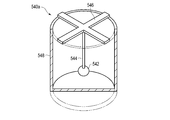
- FIG. 15 is a perspective view of the shock sensing unit 540a of the shock sensing element 540 shown in FIG.
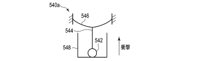
- FIG. 16 schematically shows an impact sensing unit 540 a which has received an impact in the lateral direction.
- FIG. 17 schematically shows an impact sensing unit 540 a which has received an impact along the vertical axis.
- the impact sensing element 540 is an element that senses and stores an impact along three axes.
- the shock sensing element 540 includes a shock sensing unit 540 a that senses shocks along three axes, and a storage unit 540 b that stores shocks detected by the shock sensing unit 540 a.
- the impact sensing unit 540 a is configured by a mechanical element.
- the storage unit 540 b is configured by an electrical element.
- the configuration of the storage unit 540 b is the same as the configuration of the storage unit 510 b of the shock sensing element 510.
- the impact sensing unit 540 a includes a movable electrode 542, an elastic support bar 544 supporting the movable electrode 542, an elastic support 546 supporting the elastic support bar 544, and a fixed electrode 548.
- the movable electrode 542, the elastic support rod 544, the elastic support 546, and the fixed electrode 548 all have conductivity.
- the movable electrode 542 is shaped like a sphere.
- the fixed electrode 548 is formed in a bottomed cylindrical shape.
- the elastic support bar 544 is elastically deformable and supports the movable electrode 542 so as to be movable in the lateral direction.
- the lateral direction is a direction orthogonal to the axis of the elastic support bar 544 in the non-deformed state.
- the lateral direction is decomposable into components along two axes orthogonal to the axis of the elastic support bar 544.
- the elastic support 546 is elastically deformable, and supports the movable electrode 542 and the elastic support bar 544 movably along the longitudinal axis.
- the vertical axis is an axis parallel to the axis of the elastic support bar 544 in the non-deformed state. That is, the composite of the elastic support rod 544 and the elastic support 546 supports the movable electrode 542 movably along three axes.
- the movable electrode 542 is supported inside the fixed electrode 548 by an elastic support rod 544 and an elastic support 546.
- the movable electrode 542 is disposed at a distance from the peripheral wall and the bottom wall of the fixed electrode 548.
- the movable electrode 542 is disposed on the central axis of the bottomed cylindrical fixed electrode 548.
- the elastic support 546 and the fixed electrode 548 are insulated from each other.
- the elastic support 546 is fixed to the open end of the fixed electrode 548 through an insulator.
- the fixed electrode 548 is electrically connected to one end of the capacitor 522.
- the other end of the capacitor 522 is electrically connected to one end of the electrical resistor 524.
- the other end of the electrical resistance 524 is electrically connected to the elastic support 546.
- the fixed electrode 548 and the elastic support 546 are fixed to the endoscope 110 in a state in which the impact sensing element 540 is installed in the endoscope 110.
- the capacitor 522 is charged.
- the movable electrode 542 vibrates in the lateral direction. If the magnitude of the impact is greater than the predetermined magnitude, the movable electrode 542 contacts the peripheral wall of the fixed electrode 548, as shown in FIG. As a result, the capacitor 522 discharges.
- the movable electrode 542 vibrates along the vertical axis. If the magnitude of the impact is greater than the predetermined magnitude, the movable electrode 542 contacts the bottom wall of the fixed electrode 548, as shown in FIG. As a result, the capacitor 522 discharges.
- the light source controller 226 selects the test mode of the diagnostic mode.
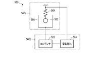
- FIG. 18 schematically shows an impact sensing element 560 according to the present modification.
- FIG. 19 schematically shows an impact sensing unit 560 a which has received an impact in the lateral direction.
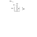
- FIG. 20 schematically shows an impact sensing unit 560 a that has received an impact along the vertical axis.
- the shock sensing element 560 is an element that senses and stores shocks along three axes, similarly to the shock sensing element 540 according to the first modification.
- the shock sensing element 560 includes a shock sensing unit 560 a that senses shocks along three axes, and a storage unit 560 b that stores shocks detected by the shock sensing unit 560 a.
- the configuration of storage unit 560 b is the same as the configuration of storage unit 510 b of impact sensing element 510.
- the impact sensing unit 560 a includes a movable electrode 562, an elastic support 564 supporting the movable electrode 562, and a fixed electrode 566.
- the movable electrode 562, the elastic support 564 and the fixed electrode 566 all have conductivity.
- the movable electrode 562 is spherically shaped.
- the fixed electrode 566 is formed in a bottomed cylindrical shape.
- the elastic support 564 is elastically deformable, and movably supports the movable electrode 562 along three axes.
- the movable electrode 562 is supported by the elastic support 564 inside the fixed electrode 566 at a distance from the peripheral wall and the bottom wall of the fixed electrode 566.
- the elastic support 564 and the fixed electrode 566 are insulated from each other.
- the fixed electrode 566 is electrically connected to one end of the capacitor 522.
- the other end of the capacitor 522 is electrically connected to one end of the electrical resistor 524.
- the other end of the electrical resistance 524 is electrically connected to the elastic support 564.
- the fixed electrode 566 and the elastic support 564 are fixed to the endoscope 110 in a state where the impact sensing element 560 is installed in the endoscope 110.
- the capacitor 522 is charged.
- the movable electrode 562 vibrates in the lateral direction.
- the magnitude of the impact is larger than the predetermined magnitude, the movable electrode 562 contacts the peripheral wall of the fixed electrode 566, as shown in FIG. As a result, the capacitor 522 discharges.
- the movable electrode 562 vibrates along the vertical axis. If the magnitude of the impact is greater than the predetermined magnitude, the movable electrode 562 contacts the bottom wall of the fixed electrode 566, as shown in FIG. As a result, the capacitor 522 discharges.
- the light source controller 226 selects the test mode of the diagnostic mode.
- Both the impact sensor 222 and the memory 224 may be configured by electrical elements. Also, the impact sensor 222 may be configured to detect the magnitude of the impact. In this case, the memory 224 is configured to store the magnitude of the shock detected by the shock sensor 222. Such impact sensor 222 is configured by, for example, an acceleration sensor. Also, the memory 224 is configured of, for example, a semiconductor memory. In this case, since the acceleration sensor and the semiconductor memory are both electrical elements that need to be supplied with power, the battery that supplies power to the shock sensor 222 and the memory 224 separately from the battery 124 is together with the shock sensor 222 and the memory 224. It is provided inside the endoscope 110.
- the impact sensor 222 detects an impact received by the endoscope 110 while the lighting device 200 is not driven, the memory 224 stores information of the impact, and the light source is activated when the endoscope system 100 is activated.
- the controller 226 acquires impact information
- the impact received by the endoscope 110 during driving of the lighting device 200 is used for the shock sensor 222 and the memory 224 to drive the lighting device 200.
- the light source controller 226 may be configured to acquire impact information.
Landscapes
- Health & Medical Sciences (AREA)
- Life Sciences & Earth Sciences (AREA)
- Surgery (AREA)
- Engineering & Computer Science (AREA)
- Biomedical Technology (AREA)
- Molecular Biology (AREA)
- Pathology (AREA)
- Radiology & Medical Imaging (AREA)
- Nuclear Medicine, Radiotherapy & Molecular Imaging (AREA)
- Biophysics (AREA)
- Physics & Mathematics (AREA)
- Heart & Thoracic Surgery (AREA)
- Medical Informatics (AREA)
- Optics & Photonics (AREA)
- Animal Behavior & Ethology (AREA)
- General Health & Medical Sciences (AREA)
- Public Health (AREA)
- Veterinary Medicine (AREA)
- General Engineering & Computer Science (AREA)
- Endoscopes (AREA)
- Arrangement Of Elements, Cooling, Sealing, Or The Like Of Lighting Devices (AREA)
Abstract
照明装置(200)は、照明光を出射する照明系(210)と、衝撃を検知する衝撃センサ(222)と、衝撃センサ(222)により検知された衝撃の情報を記憶するメモリ(224)と、メモリ(224)に記憶されている衝撃の情報に基づいて、照明系(210)の故障の有無を診断する診断テストを行う光源コントローラ(226)を備えている。
Description
本発明は、照明装置に関する。
例えば日本国特許第4732783号は、ライトガイドと、ライトガイドの先端側に配置された蛍光体と、蛍光体を励起する励起光を射出する半導体レーザ光源と、励起光をライトガイドの後端へ集光する集光レンズとを備えた内視鏡用照明装置を開示している。
同文献はまた、内視鏡用照明装置を内蔵した内視鏡を有する内視鏡システムを開示している。
本発明の目的は、故障の有無を診断する診断テストを効率良く行う照明装置および診断方法を提供することである。
本発明による照明装置は、照明光を出射する照明系と、衝撃を検知する衝撃センサと、前記衝撃センサにより検知された衝撃の情報を記憶するメモリと、前記メモリに記憶されている衝撃の情報に基づいて、前記照明系の故障の有無を診断する診断テストを行う光源コントローラとを有する。
本発明による診断方法は、照明光を出射する照明系と、衝撃を検知する衝撃センサと、前記衝撃センサにより検知された衝撃の情報を記憶するメモリとを有する照明装置の診断方法であり、前記メモリに記憶されている衝撃の情報に基づいて、前記照明系の故障の有無を診断する診断テストを行う。
本発明によれば、故障の有無を診断する診断テストを効率良く行う照明装置および診断方法が提供される。
図1は、実施形態に係る内視鏡システム100を示している。内視鏡システム100は、観察対象物を撮像する内視鏡110と、内視鏡110によって撮像された画像の処理等を行う制御装置160と、内視鏡110によって撮像された画像を表示するモニタ180を有している。
内視鏡110は、ワイヤレス内視鏡で構成されており、内視鏡110と制御装置160の間の信号の送受信は無線で行われる。
内視鏡110は、観察対象物の管腔や管路等の空所に挿入される中空の細長い挿入部130と、挿入部130の基端側に連結された操作部120とを有している。
挿入部130は、先端に位置する先端硬質部132と、先端硬質部132の基端側に連結された湾曲部134と、湾曲部134の基端側に連結された可撓管部136とを有している。湾曲部134は、操作部120を操作することにより所望の方向に湾曲可能に構成されている。可撓管部136は、湾曲自在であり、例えば、観察対象物の管腔や管路等の形状に倣って湾曲可能である。
操作部120は、湾曲部134を湾曲させるための操作ダイヤル122を有している。操作部120には、内視鏡110の内部の電気部品(例えば、後述する照明装置200や撮像素子272、送信機274)に電力を供給するバッテリー124が装着される。
通常、バッテリー124は、内視鏡110が使用されていない間は、操作部120から外されており、次回の使用時に、操作部120に装着される。従って、内視鏡110が使用されていない間、内視鏡110には電力が供給されない。
ワイヤレスの内視鏡110は、ユニバーサルコードがないため、ユニバーサルコードに引っ張られることなく内視鏡110の姿勢や位置を変えることができることなどから、利便性に優れている。
図2は、図1に示された内視鏡システム100の機能ブロックを示している。図2に示されるように、内視鏡システム100は、前述したように、内視鏡110と制御装置160とモニタ180を有している。
内視鏡110は、照明装置200を内蔵している。照明装置200は、観察対象物を照明するための照明系210を有している。照明系210は、光源212と、結合レンズ214と、導光部材である光ファイバ216と、入射する光を照明光に変換する光変換素子218を有している。
光源212と結合レンズ214は、操作部120の内部に配置されている。光ファイバ216は、挿入部130の中を通って延びている。光変換素子218は、挿入部130の先端硬質部132の内部に配置されている。
光源212は、これに限らないが、本実施形態では、レーザ光源、例えばレーザダイオードで構成されている。結合レンズ214は、光源212から発せられた光を光ファイバ216に結合する。光ファイバ216は、入射した光を光変換素子218まで導光する。光変換素子218は、光ファイバ216から入射した光を、所望の品質を有する照明光に変換する。
所望の品質を有する照明光は、好ましくは、配光が広く、ほぼ一定した強度分布を有する光である。光変換素子218は、例えば、入射した光を拡散させる拡散体で構成される。光変換素子218はまた、入射した光を吸収して、入射した光の波長とは異なる波長の光を発する蛍光体で構成されてもよい。
内視鏡システム100は、観察対象物を撮像するための撮像系270を有している。撮像系270は、観察対象物からの光を受光して観察対象物の光学像の画像信号を出力する撮像素子272と、撮像素子272から出力される画像信号を無線で送信する送信機274と、送信機274から送信された画像信号を受信する受信機276と、受信機276によって受信された画像信号を処理する画像処理回路278を有している。
撮像素子272は、挿入部130の先端硬質部132の内部に配置されている。送信機274は、操作部120の内部に配置されている。受信機276と画像処理回路278は、制御装置160の内部に配置されている。ここでは、画像処理回路278が制御装置160の内部に配置されているが、画像処理回路278の一部が内視鏡110の内部に配置されてもよい。
内視鏡110の使用後から次回の使用時までの間に、例えば、内視鏡110の洗浄時等の非使用時に、作業者が取り扱いを誤って、内視鏡110を落下させて床に激突させたり、他の物体に衝突させたりしたために、内視鏡110が衝撃を受けた場合、照明装置200の照明系210が損傷することが考えられる。照明系210の光ファイバ216や光変換素子218が破損した場合、次回の使用時に、所望の品質を有する照明光が出射されない等の不具合が生じるおそれがある。
これは、ワイヤレスの内視鏡110に限った話ではなく、ユニバーサルコードを有する通常の内視鏡においても言えることである。
所望の品質を有する照明光が出射されない等の事態を避けるため、照明装置200は、内視鏡システム100の起動時に、照明系210の故障の有無を診断し、照明系210に損傷がないことを確認した後に駆動するように構成されている。作業者が誤って内視鏡から手を離してしまった場合、ユニバーサルコードが無いワイヤレス内視鏡は、そのまま地面に落ちることがある。従って、ワイヤレス内視鏡は、照明系に損傷がないことを確認した後に駆動することがより重要である。
照明装置200は、さらに、内視鏡110の非使用時の間に、言い換えれば、照明装置200が駆動されていない間に、内視鏡110が受けた衝撃を検知し、その検知結果に基づいて、照明系210の故障の有無を診断する診断テストの内容を変更するように構成されている。なお、照明装置200が駆動されていない間は、照明装置200に対する電力供給がない状態と言い換えてもよい。
このため、照明装置200は、衝撃を検知する衝撃センサ222と、衝撃センサ222によって検知された衝撃を記憶するメモリ224を有している。
衝撃センサ222とメモリ224は、繰り返し使用できるように構成されている。衝撃センサ222とメモリ224は、例えば線材の断線のように部材の破損によって衝撃を検知したり情報を記憶したりする形態は含まない。
衝撃センサ222は、照明装置200が駆動されていない間に、言い換えれば、照明装置200が電力供給を受けていない間に、衝撃を検知するように構成されている。衝撃センサ222は、照明装置200が駆動されている間も、衝撃を検知するように構成されていてもよい。
衝撃センサ222は、例えば、光変換素子218の近くに配置されている。光変換素子218が破損したり脱落したりした場合、光ファイバ216から出射したレーザ光が、光変換素子218によって適切に変換されず、例えば、光変換素子218が拡散体である場合に、拡散体によって十分に拡散されず、そのために、所望の品質から外れたレーザ光が内視鏡110の挿入部130の先端から出射する可能性がある。つまり、光変換素子218は、所望の品質を有する照明光の出射にとって、重要な光学部品である。従って、光変換素子218の近くは、衝撃センサ222の配置個所として、適当と考えられる候補の一つである。
衝撃センサ222は、例えば、光ファイバ216の近くに配置されている。光ファイバ216が破損した場合、光ファイバ216から出射したレーザ光が、適切に導光されなくなり、場合によっては、内視鏡110の挿入部130の先端から出射する可能性がある。このように、光ファイバ216もまた、所望の品質を有する照明光の出射にとって、重要な光学部品である。従って、光ファイバ216の近くもまた、衝撃センサ222の配置個所として、適当と考えられる候補の一つである。
衝撃センサ222は、例えば、先端硬質部132の内部に配置されている。先端硬質部132は、内視鏡110の非使用時に、床や他の物体等に衝突することが多いと考えられる個所でもあり、また、衝突した場合に強い衝撃を受けやすいと考えられる個所である。従って、先端硬質部132の内部もまた、衝撃センサ222の配置個所として、適当と考えられる候補の一つである。
衝撃センサ222は、例えば、操作部120の内部に配置されている。操作部120は、内視鏡110が床に落下した場合に、強い衝撃を受けやすいと考えられる個所である。従って、操作部120の内部もまた、衝撃センサ222の配置個所として、適当と考えられる候補の一つである。
衝撃センサ222は、ここに述べた個所に限らず、安全な強度のレーザ光の出射にとって重要である他の光学部品の近くや強い衝撃を受けやすいと考えられる他の個所に配置されてもよい。
照明装置200は、ただ1つの衝撃センサ222を有していてもよいし、複数の衝撃センサ222を有していてもよい。複数の衝撃センサ222は、ここに述べた個所および/または他の個所に配置されてもよい。
衝撃センサ222は、例えば、単一の衝撃センシング素子で構成されている。単一の衝撃センシング素子は、例えば、複数軸たとえば3軸に沿った衝撃を検知するように構成されている。
あるいは、衝撃センサ222は、複数の衝撃センシング素子の複合体で構成されていてもよい。各衝撃センシング素子は、例えば、1軸に沿った衝撃を検知するように構成されている。この場合、衝撃センサ222は、互いに異なる軸に沿った衝撃を検知する3個の衝撃センシング素子を含んでいるとよい。あるいは、各衝撃センシング素子は、1方向の衝撃を検知するように構成されていてもよい。この場合、衝撃センサ222は、好ましくは、互いに異なる方向の衝撃を検知する6個の衝撃センシング素子を含んでいるとよい。
衝撃センサ222は、例えば、感度の異なる複数の衝撃センシング素子を有していてもよい。この場合、メモリ224は、複数の衝撃センシング素子によって検知された衝撃をそれぞれ記憶する複数の記憶素子を有している。
例えば、衝撃センサ222とメモリ224は共に、機械的素子によって構成されている。ここにおいて、機械的素子は、電気を利用することなく、機能する素子を意味している。すなわち、衝撃センサ222とメモリ224は、電気を利用することなく機能するように構成されている。すなわち、衝撃センサ222は、機械的なセンサで構成されている。また、メモリ224は、機械的なメモリで構成されている。
例えば、衝撃センサ222は、所定の大きさを超える衝撃を検知するように構成されている。これに応じて、メモリ224は、衝撃センサ222により検知された衝撃の履歴を記憶するように構成されている。
衝撃センサ222とメモリ224は、例えば、一体に構成されている。言い換えれば、衝撃センサ222とメモリ224は、単一の機械的素子によって構成されている。このような機械的素子の具体例については、図8~図12を参照しながら後述する。
あるいは、衝撃センサ222は、機械的素子で構成されており、メモリ224は、電気的素子によって構成されていてもよい。ここにおいて、電気的素子は、電気を利用して機能する素子を意味している。その具体例については、図13~図20を参照しながら後述する。
照明装置200はまた、光源212を制御する光源コントローラ226を有している。光源コントローラ226は、例えば、予めプログラムされたソフトウェアに従って動作を行うマイコンや集積回路等によって構成されてよい。光源コントローラ226は、各種の駆動モードに従って光源212を制御するように構成されている。
駆動モードは、例えば、内視鏡システム100による観察対象物の観察のための照明光を出射する通常モードと、内視鏡システム100の起動時に照明系210の故障の有無を診断する診断テストのための照明光を出射する診断モードを含んでいる。
光源コントローラ226は、例えば、安全のため、診断モードにおいては、通常モードにおいて光源212から発せられる光よりも弱い光である診断テストのための照明光が光源212から発せられるように、光源212を制御する。
診断モードは、診断テストのために用意された複数のテスト項目に関して、診断テストにおいて実施または省略されるテスト項目に応じて、複数のテストモードを含んでいる。
複数のテストモードは、診断テストのために用意された複数のテスト項目に関して、すべてのテスト項目が実施される完全テストモードと、完全テストモードとは異なる非完全テストモードとに分けられる。非完全テストモードによる診断テストは、完全テストモードよる診断テストと比べて短時間で実施可能である。
非完全テストモードは、複数のテスト項目中の少なくともひとつのテスト項目の実施が省略され、複数のテスト項目中の残りのテスト項目が実施される簡易テストモードと、複数のテスト項目のいずれも実施されないテスト省略モードとを含んでいる。
簡易テストモードは、実施が省略されるテスト項目に応じて、様々なモードを含んでいる。
光源コントローラ226は、診断モードにおいては、メモリ224に記憶されている衝撃の情報に基づいて、複数のテストモードの中から1つのテストモードを選択し、選択したテストモードに従って光源212を駆動するように構成されている。
光源コントローラ226はまた、診断モードにおいては、撮像素子272から出力される画像信号に基づいて、照明系210の故障の有無を診断するように構成されている。
診断モードにおいては、照明系210から出射された照明光が、シャッタ242によって反射された後に撮像素子272に入射するようにするため、内視鏡110の挿入部130の先端にシャッタ242が設けられる。シャッタ242は、例えば、ホワイトバランスキャップで構成される。シャッタ242は、適度な反射率を有してさえいれば、どんな部材で構成されてもよい。
[内視鏡システム起動時の光源装置の動作]
次に、本実施形態に係る照明装置200の動作について説明する。図3は、内視鏡システム100の起動と、それに伴う照明装置200における処理のフローチャートを示している。図3の処理は、光源コントローラ226が主体となっておこなわれる。
次に、本実施形態に係る照明装置200の動作について説明する。図3は、内視鏡システム100の起動と、それに伴う照明装置200における処理のフローチャートを示している。図3の処理は、光源コントローラ226が主体となっておこなわれる。
図3のフローチャートは、内視鏡システム100の起動前の状態から、内視鏡システム100の起動時の診断を経て、照明装置200が、通常モードによる光源212の駆動に移るか、照明系210の故障を通知するまでを表している。
ステップS1において、内視鏡システム100が起動された後、ステップS2において、光源コントローラ226は、メモリ224に記憶されている衝撃の情報をチェックする。例えば、衝撃センサ222は、所定の大きさを超える衝撃を検知するように構成されており、メモリ224は、衝撃センサ222により検知された衝撃の履歴(衝撃が検知されたこと)を記憶するように構成されている。この場合、メモリ224に記憶されている衝撃の情報は、衝撃センサ222により検知された衝撃の履歴である。
ステップS3において、光源コントローラ226は、メモリ224に記憶されている衝撃の履歴が、衝撃センサ222が衝撃を検知したことを示すか否かを判定する。衝撃の履歴が、衝撃センサ222が衝撃を検知したことを示すと判定された場合、処理はステップS4に移行する。反対に、衝撃の履歴が、衝撃センサ222が衝撃を検知しなかったことを示すと判定された場合、処理はステップS8に移行する。
ステップS3において、衝撃の履歴が、衝撃センサ222が衝撃を検知したことを示すと判定された場合、ステップS4において、光源コントローラ226は、完全テストモードを選択し、完全テストモードに従って光源212を駆動するとともに、撮像素子272から出力される画像信号に基づいて、照明系210の故障の有無を診断する。完全テストモードによる診断を、便宜上、完全チェックと称する。
光源コントローラ226はまた、診断を行っている間、完全テストモードによる診断を行っていることを通知する。例えば、光源コントローラ226は、完全テストモードによる診断を行っていることを示すメッセージをモニタ180に表示させる。その後、処理はステップS5に移行する。
ステップS5において、光源コントローラ226は、照明系210に故障があるか否かを判定する。照明系210に故障がないと判定された場合、処理はステップS6に移行する。反対に、照明系210に故障があると判定された場合、処理はステップS10に移行する。
ステップS5において、照明系210に故障がないと判定された場合、ステップS6において、光源コントローラ226は、メモリ224に記憶されている衝撃の情報、例えば、衝撃の履歴をリセットする。その後、処理はステップS7に移行する。
ステップS7において、光源コントローラ226は、通常モードで光源212を駆動する。
ステップS3において、衝撃の履歴が、衝撃センサ222が衝撃を検知しなかったことを示すと判定された場合、ステップS8において、光源コントローラ226は、非完全テストモードを選択し、非完全テストモードに従って光源212を駆動するとともに、撮像素子272から出力される画像信号に基づいて、照明系210の故障の有無を診断する。ここでは、光源コントローラ226は、非完全テストモードとして、簡易テストモードを選択して、照明系210の故障の有無を診断するものとする。簡易テストモードによる診断を、便宜上、簡易チェックと称する。
光源コントローラ226はまた、診断を行っている間、簡易テストモードによる診断を行っていることを通知する。例えば、光源コントローラ226は、簡易テストモードによる診断を行っていることを示すメッセージをモニタ180に表示させる。その後、処理はステップS9に移行する。
ステップS9において、光源コントローラ226は、照明系210に故障があるか否かを判定する。照明系210に故障がないと判定された場合、処理はステップS7に移行する。反対に、照明系210に故障があると判定された場合、処理はステップS10に移行する。
ステップS5またはステップS9において、照明系210に故障があると判定された場合、ステップS10において、光源コントローラ226は、照明系210に故障があることを通知する。例えば、光源コントローラ226は、照明系210に故障があることを示すメッセージをモニタ180に表示させる。
[診断テストのテスト項目の一例]
図4は、完全テストモードによる診断において実施されるテスト項目の測定結果を示したグラフである。また、図5は、簡易テストモードによる診断において実施されるテスト項目の測定結果を示したグラフである。これらのグラフにおいて、横軸は、光源212に供給する電流の大きさを示しており、縦軸は、照明系210から出射する光の強度(輝度)、詳しくは、光変換素子218から放出されシャッタ242で反射され撮像素子272に入射する光の強度を示している。
図4は、完全テストモードによる診断において実施されるテスト項目の測定結果を示したグラフである。また、図5は、簡易テストモードによる診断において実施されるテスト項目の測定結果を示したグラフである。これらのグラフにおいて、横軸は、光源212に供給する電流の大きさを示しており、縦軸は、照明系210から出射する光の強度(輝度)、詳しくは、光変換素子218から放出されシャッタ242で反射され撮像素子272に入射する光の強度を示している。
完全テストモードにおいては、光源コントローラ226は、先ず、電流値I1の電流を光源212に供給し、撮像素子272から出力される画像信号に基づいて、電流値I1に対する光強度値P1を測定する。光強度値P1は、例えば、撮像素子272の各画素の出力信号の総和であってよい。次に、光源コントローラ226は、光源212に供給する電流の大きさを電流値I2に変更し、電流値I2に対する光強度値P2を測定する。以下、同様にして、光源コントローラ226は、電流値I3,I4,I5の電流の供給と、光強度値P3,P4,P5の測定を行う。
その結果、図4に示されるように、5つの電流値I1~I5のそれぞれに対する光強度値P1~P5が得られる。光源コントローラ226は、5つの電流値I1~I5に対する5つの光強度値P1~P5のすべてが、それぞれの規格範囲S1~S5内に納まっている場合、照明系210に故障はないと判断する。光源コントローラ226は、5つの電流値I1~I5に対する5つの光強度値P1~P5のいずれか1つでも、それぞれの規格範囲S1~S5から外れている場合、照明系210に故障があると判断する。
ここでは、便宜上、5つの電流値I1~I5のすべてについて光強度値P1~P5を測定した後に、5つの光強度値P1~P5が、それぞれの規格範囲S1~S5内に納まっているか否かを判定するとして説明したが、1つの電流値について光強度値を測定した時点で、測定した光強度値が規格範囲内に納まっているか否かを判定するようにしてもよい。この場合、測定した光強度値が規格範囲内に納まっていないことが判明した時点で、照明系210に故障があることを通知し、残りの電流値に対する光強度値の測定を省略してよい。このようにすることにより、照明系210に故障がある場合に、診断テストの所要時間の短縮が見込める。
一方、簡易テストモードにおいては、光源コントローラ226は、電流値I5の電流を光源212に供給し、撮像素子272から出力される画像信号に基づいて、電流値I5に対する光強度値P5を測定する。その結果、図5に示されるように、1つの電流値I5に対する光強度値P5が得られる。光源コントローラ226は、光強度値P5が規格範囲S5内に納まっている場合、照明系210に故障はないと判断する。光源コントローラ226は、光強度値P5が規格範囲S5から外れている場合、照明系210に故障があると判断する。
ここでは、簡易テストモードおいて、最も高い電流値I5に対する光強度値P5が測定されているが、電流値(確認点)は、これに限定されない。他の電流値I1~I4のいずれかに対する光強度値が測定されてもよい。
ここにおいて、1つの電流値に対する光強度値の測定と、測定した光強度値に基づく照明系210の故障の有無の判断を、1つのテスト項目とする。完全テストモードにおいては、5つのテスト項目を行い、簡易テストモードにおいては、1つのテスト項目を行う。
これまでの説明から分かるように、本実施形態に係る照明装置200においては、内視鏡110が所定の大きさを超える衝撃を受けた、従って、照明系210に故障が生じたおそれがある場合には、すべてのテスト項目を実施する完全テストモードによる診断テスト、言い換えれば、照明系210の故障の有無を入念にチェックする診断テストが行われ、反対に、内視鏡110が所定の大きさを超える衝撃を受けていない、従って、照明系210に故障が生じたおそれが実質的にない場合には、少なくとも1つのテスト項目を省略してテスト項目を実施する簡易テストモードによる診断テスト、言い換えれば、所要時間の短い診断テスト、または、テスト項目をまったく実施しないテスト省略モードによる診断テスト、言い換えれば、診断テストそのものの省略が行われる。
これにより、照明系210の故障の有無を診断する診断テストが効率良く行われる。つまり、内視鏡110が使用されていない間に、照明系210に故障が生じたおそれが実質的にない場合には、少なくとも1つのテスト項目の実施またはすべてのテスト項目の実施が省略されるため、診断テストに要する時間が短くて済む。
ここに説明した、光源212に供給する電流に対する光変換素子218から放出される照明光の光強度(輝度)の測定は、テスト項目のほんの一例に過ぎない。また、完全テストモードと簡易テストモードの違いは、電流値の数の違いに限定されない。
テスト項目は、例えば、(α)光源212に供給する電流に対する光変換素子218から放出される照明光の光強度(輝度)の測定、(β)光変換素子218から放出される照明光の色調の測定、(γ)光変換素子218から放出される照明光の輝度ムラの測定を含んでいる。
テスト項目(α)では、前述したように、光源212に供給する電流に対する光変換素子218から放出される照明光の強度(輝度)が測定される。輝度の測定は、撮像素子272から出力される画像信号に基づいて行われる。照明系210の故障の有無は、測定した輝度が予め定めた輝度の範囲(規格範囲)内に入っているか否かで判断される。
テスト項目(β)では、光変換素子218から放出される照明光の色調が測定される。色調の測定は、撮像素子272から出力される画像信号に基づいて行われる。照明系210の故障の有無は、測定した色調が予め定めた色調の範囲内に入っているか否かで判断される。
テスト項目(γ)では、光変換素子218から放出される照明光の輝度ムラが測定される。輝度ムラの測定は、撮像素子272から出力される画像信号に基づいて行われる。照明系210の故障の有無は、測定した輝度ムラが予め定めた輝度ムラの範囲内に入っているか否かで判断される。
以下に、完全テストモードにおいて実施されるテスト項目と、簡易テストモードにおいて実施されるテスト項目の組み合わせ例を示す。
[診断テストのテスト項目の例1]
完全テストモードにおいては、5つの電流値について、テスト項目(α)を行う。簡易テストモードにおいては、1つの電流値について、テスト項目(α)を行う。
完全テストモードにおいては、5つの電流値について、テスト項目(α)を行う。簡易テストモードにおいては、1つの電流値について、テスト項目(α)を行う。
1つの電流値についてのテスト項目(α)を1つのテスト項目とする。すなわち、完全テストモードにおいては、5つのテスト項目(α)を行い、簡易テストモードにおいては、1つのテスト項目(α)を行う。尚、テスト項目(α)の数は例示に過ぎず、完全テストモードのテスト項目(α)の数が簡易テストモードのテスト項目(α)の数より多ければよい。
[診断テストのテスト項目の例2]
完全テストモードと簡易テストモードのいずれにおいても、テスト項目(α)を行う。完全テストモードにおける規格範囲と簡易テストモードにおける規格範囲は異なっている。詳しくは、簡易テストモードにおける規格範囲は、完全テストモードにおける規格範囲よりも広い。
完全テストモードと簡易テストモードのいずれにおいても、テスト項目(α)を行う。完全テストモードにおける規格範囲と簡易テストモードにおける規格範囲は異なっている。詳しくは、簡易テストモードにおける規格範囲は、完全テストモードにおける規格範囲よりも広い。
テスト項目(α)は、例えば1つの電流値について行う。もちろん、テスト項目(α)は、複数の電流値について行ってもよい。
[診断テストのテスト項目の例3]
完全テストモードにおいては、テスト項目(α)とテスト項目(β)を順に行う。簡易テストモードにおいては、テスト項目(α)だけを行う。
完全テストモードにおいては、テスト項目(α)とテスト項目(β)を順に行う。簡易テストモードにおいては、テスト項目(α)だけを行う。
テスト項目(α)は、完全テストモードと簡易テストモードのいずれにおいても、例えば1つの電流値について行う。もちろん、テスト項目(α)は、複数の電流値について行ってもよい。さらには、完全テストモードにおいては、簡易テストモードにおける電流値よりも多くの電流値についてテスト項目(α)を行ってもよい。
完全テストモードにおいて、照明系210に故障があるか否かの判定は、テスト項目が完了する度に行う。テスト項目(α)を完了した時点で、照明系に故障があると判定された場合は、残りのテスト項目(β)を行うことなく、照明系210に故障があることを通知し、診断テストを終了する。
[診断テストのテスト項目の例4]
完全テストモードにおいては、テスト項目(α)とテスト項目(β)を順に行う。簡易テストモードにおいては、テスト項目(β)だけを行う。
完全テストモードにおいては、テスト項目(α)とテスト項目(β)を順に行う。簡易テストモードにおいては、テスト項目(β)だけを行う。
テスト項目(α)は、例えば1つの電流値について行う。もちろん、テスト項目(α)は、複数の電流値について行ってもよい。
完全テストモードにおいて、照明系210に故障があるか否かの判定は、テスト項目が完了する度に行う。テスト項目(α)を完了した時点で、照明系に故障があると判定された場合は、テスト項目(β)を行うことなく、照明系210に故障があることを通知し、診断テストを終了する。
[診断テストのテスト項目の例5]
完全テストモードにおいては、テスト項目(α)とテスト項目(β)を順に行う。簡易テストモードにおいては、テスト項目(γ)を行う。
完全テストモードにおいては、テスト項目(α)とテスト項目(β)を順に行う。簡易テストモードにおいては、テスト項目(γ)を行う。
テスト項目(α)は、例えば1つの電流値について行う。もちろん、テスト項目(α)は、複数の電流値について行ってもよい。
完全テストモードにおいて、照明系210に故障があるか否かの判定は、テスト項目が完了する度に行う。テスト項目(α)を完了した時点で、照明系に故障があると判定された場合は、テスト項目(β)を行うことなく、照明系210に故障があることを通知し、診断テストを終了する。
[診断テストのテスト項目の例6]
完全テストモードにおいては、テスト項目(α)とテスト項目(γ)を順に行う。簡易テストモードにおいては、テスト項目(γ)だけを行う。
完全テストモードにおいては、テスト項目(α)とテスト項目(γ)を順に行う。簡易テストモードにおいては、テスト項目(γ)だけを行う。
テスト項目(α)は、例えば1つの電流値について行う。もちろん、テスト項目(α)は、複数の電流値について行ってもよい。
完全テストモードにおいて、照明系210に故障があるか否かの判定は、テスト項目が完了する度に行う。テスト項目(α)を完了した時点で、照明系に故障があると判定された場合は、テスト項目(γ)を行うことなく、照明系210に故障があることを通知し、診断テストを終了する。
[診断テストのテスト項目の例7]
テスト項目(β)の所要時間は、テスト項目(α)の所要時間よりも短いと仮定した場合について述べる。
テスト項目(β)の所要時間は、テスト項目(α)の所要時間よりも短いと仮定した場合について述べる。
完全テストモードにおいては、テスト項目(β)とテスト項目(α)を順に行う。簡易テストモードにおいては、テスト項目(α)又はテスト項目(β)の一方だけを行う。尚、簡易テストモードではテスト項目(β)を実施した方が、簡易チェックの所要時間をより短縮する観点では好ましい。
テスト項目(α)は、例えば1つの電流値について行う。もちろん、テスト項目(α)は、複数の電流値について行ってもよい。
完全テストモードにおいて、照明系210に故障があるか否かの判定は、テスト項目が完了する度に行う。テスト項目(β)を完了した時点で、照明系210に故障があると判定された場合は、テスト項目(α)を行うことなく、照明系210に故障があることを通知し、診断テストを終了する。これにより、照明系210に故障がある場合に、そのことをより早く通知し、診断テストをより早く終了できる。
[診断テストのテスト項目の例8]
テスト項目(α)の所要時間は、テスト項目(β)の所要時間よりも短いと仮定した場合について述べる。
テスト項目(α)の所要時間は、テスト項目(β)の所要時間よりも短いと仮定した場合について述べる。
完全テストモードにおいては、テスト項目(α)とテスト項目(β)を順に行う。簡易テストモードにおいては、テスト項目(α)又はテスト項目(β)の一方だけを行う。尚、簡易テストモードではテスト項目(α)を実施した方が、簡易チェックの所要時間をより短縮する観点では好ましい。
テスト項目(α)は、例えば1つの電流値について行う。もちろん、テスト項目(β)は、複数の電流値について行ってもよい。
完全テストモードにおいて、照明系210に故障があるか否かの判定は、テスト項目が完了する度に行う。テスト項目(α)を完了した時点で、照明系に故障があると判定された場合は、テスト項目(β)を行うことなく、照明系210に故障があることを通知し、診断テストを終了する。これにより、照明系210に故障がある場合に、そのことをより早く通知し、診断テストをより早く終了できる。
[診断テストのテスト項目の例9]
衝撃センサ222は、高感度の第1の衝撃センシング素子と、低感度の第2の衝撃センシング素子を有している。メモリ224は、第1の衝撃センシング素子によって検知された衝撃を記憶する第1の記憶素子と、第2の衝撃センシング素子によって検知された衝撃を記憶する第2の記憶素子を有している。簡易テストモードは、第1の簡易テストモードと第2の簡易テストモードを有している。
衝撃センサ222は、高感度の第1の衝撃センシング素子と、低感度の第2の衝撃センシング素子を有している。メモリ224は、第1の衝撃センシング素子によって検知された衝撃を記憶する第1の記憶素子と、第2の衝撃センシング素子によって検知された衝撃を記憶する第2の記憶素子を有している。簡易テストモードは、第1の簡易テストモードと第2の簡易テストモードを有している。
光源コントローラ226は、第1の記憶素子と第2の記憶素子に記憶されている衝撃の情報に基づいてテストモードを選択する。例えば、光源コントローラ226は、第1の記憶素子に記憶されている衝撃の情報が、第1の衝撃センシング素子が衝撃を検知したことを示し、かつ、第2の記憶素子に記憶されている衝撃の情報が、第2の衝撃センシング素子が衝撃を検知したことを示す場合、完全テストモードを選択する。
また、光源コントローラ226は、第1の記憶素子に記憶されている衝撃の情報が、第1の衝撃センシング素子が衝撃を検知したことを示し、かつ、第2の記憶素子に記憶されている衝撃の情報が、第2の衝撃センシング素子が衝撃を検知しなかったことを示す場合、第1の簡易テストモードを選択する。
また、光源コントローラ226は、第1の記憶素子に記憶されている衝撃の情報が、第1の衝撃センシング素子が衝撃を検知しなかったことを示し、かつ、第2の記憶素子に記憶されている衝撃の情報が、第2の衝撃センシング素子が衝撃を検知しなかったことを示す場合、第2の簡易テストモードを選択する。
完全テストモードにおいては、5つの電流値について、テスト項目(α)を行う。言い換えれば、完全テストモードにおいては、電流値を変えて、5つのテスト項目(α)を行う。第1の簡易テストモードにおいては、3つの電流値について、テスト項目(α)を行う。言い換えれば、第1の簡易テストモードにおいては、電流値を変えて、3つのテスト項目(α)を行う。第2の簡易テストモードにおいては、1つの電流値について、テスト項目(α)を行う。言い換えれば、第2の簡易テストモードにおいては、1つのテスト項目(α)を行う。
[診断テストのテスト項目の例10]
簡易テストモードは、第1の簡易テストモードと第2の簡易テストモードを有している。衝撃センサ222とメモリ224の構成は、例9の場合と同様である。第1の簡易テストモードと第2の簡易テストモードの選択の仕方も、例9の場合と同様である。
簡易テストモードは、第1の簡易テストモードと第2の簡易テストモードを有している。衝撃センサ222とメモリ224の構成は、例9の場合と同様である。第1の簡易テストモードと第2の簡易テストモードの選択の仕方も、例9の場合と同様である。
完全テストモードにおいては、テスト項目(β)とテスト項目(α)とテスト項目(γ)を順に行う。第1の簡易テストモードにおいては、テスト項目(α)とテスト項目(γ)を順に行う。第2の簡易テストモードにおいては、テスト項目(α)だけ行う。
テスト項目(β)の所要時間は、テスト項目(α)の所要時間よりも短い。テスト項目(α)の所要時間は、テスト項目(γ)の所要時間よりも短い。つまり、完全テストモードと第1の簡易テストモードにおいては、所要時間の短いテスト項目を先に行い、所要時間の長いテスト項目を後で行う。
テスト項目(α)は、例えば1つの電流値について行う。もちろん、テスト項目(β)は、複数の電流値について行ってもよい。
完全テストモードにおいて、テスト項目(β)を完了した時点で、照明系に故障があると判定された場合は、残りのテスト項目(α)とテスト項目(γ)を行うことなく、照明系210に故障があることを通知し、診断テストを終了する。また、完全テストモードと第1の簡易テストモードにおいて、テスト項目(α)を完了した時点で、照明系に故障があると判定された場合は、残りのテスト項目(γ)を行うことなく、照明系210に故障があることを通知し、診断テストを終了する。
[診断テストのテスト項目の例11]
簡易テストモードにおけるテスト項目(α)において、照明系210の故障の有無は、測定した輝度が予め定めた輝度の範囲(規格範囲)内に入っているか否かで判断される代わりに、内視鏡110の前回の使用時に測定した輝度と比較することにより判断されてもよい。
簡易テストモードにおけるテスト項目(α)において、照明系210の故障の有無は、測定した輝度が予め定めた輝度の範囲(規格範囲)内に入っているか否かで判断される代わりに、内視鏡110の前回の使用時に測定した輝度と比較することにより判断されてもよい。
図6と図7は、図5と同様のグラフであり、このような簡易テストモードにおいて、光源212に供給する電流に対する照明系210から出射する照明光の輝度を測定するテスト項目(α)を示したグラフである。グラフにおいて、Ppは、前回測定した輝度値を示し、Pnは、今回測定した輝度値を示し、Saは、輝度値Pp,Pnに対する規格範囲を示し、Sbは、輝度値Pp,Pnの差分(Pn-Pp)に対する規格範囲を示し、Scは、輝度値Pp,Pnに対する最低規格範囲を示している。
光源コントローラ226は、前回測定した輝度値を記憶している。光源コントローラ226は、光源212に電流を供給し、撮像素子272から出力される画像信号に基づいて、その電流値に対する輝度値Pnを測定する。次に、光源コントローラ226は、今回測定した輝度値Pnと前回測定した輝度値Ppの差分(Pn-Pp)を求める。続いて、光源コントローラ226は、差分(Pn-Pp)を規格範囲Sbと比較する。
図6に示されるように、今回測定した輝度値Pnが、規格範囲Saから外れている場合であっても、差分(Pn-Pp)が、規格範囲Sb内に納まっている場合には、光源コントローラ226は、照明系210に故障はないと判断する。反対に、差分(Pn-Pp)が、規格範囲Sbから外れている場合には、光源コントローラ226は、照明系210に故障があると判断する。
しかし、図7に示されるように、今回測定した輝度値Pnは、規格範囲Saから外れているが、差分(Pn-Pp)は、規格範囲Sb内に納まっている場合であっても、今回測定した輝度値Pnが、最低規格範囲Scから外れている場合には、光源コントローラ226は、照明系210に故障があると判断する。なお、最低規格範囲Scは、照明系210から出射する照明光の輝度が最低限満たしていなければならない規格範囲である。
[衝撃センサ222とメモリ224の構成例1]
衝撃センサ222とメモリ224のひとつの構成例について図8~図10を参照しながら説明する。図8は、衝撃センサ222の機能とメモリ224の機能とを有する複合衝撃センサ300を示している。図9は、図8に示された衝撃センシング素子310を分解して示している。図10は、衝撃を受ける前後における図8に示された衝撃センシング素子310の断面を示している。
衝撃センサ222とメモリ224のひとつの構成例について図8~図10を参照しながら説明する。図8は、衝撃センサ222の機能とメモリ224の機能とを有する複合衝撃センサ300を示している。図9は、図8に示された衝撃センシング素子310を分解して示している。図10は、衝撃を受ける前後における図8に示された衝撃センシング素子310の断面を示している。
複合衝撃センサ300は、1方向の衝撃を感知して記憶する衝撃センシング素子310を有している。衝撃センシング素子310は、機械的素子で構成されている。衝撃センシング素子310は、固定子312と、可動子314を有している。固定子312と可動子314は共に、絶縁体で構成されている。固定子312は、衝撃センシング素子310が内視鏡110に設置された状態において、内視鏡110に固定されている。可動子314は、固定子312の端部に装着されている。以下では、可動子314が装着された側の端部を先端部、その反対側の端部を基端部と称する。
例えば、固定子312は円筒形状に形作られており、可動子314は有底円筒形状に形作られている。言い換えれば、可動子314は凹部を有している。固定子312と可動子314を有する衝撃センシング素子310は、これに限らないが、例えば、100μm程度の直径を有し、数mm程度の長さを有している。固定子312と可動子314の形状は単なる一例であり、これに限定されるものではなく、ここに述べている機能を有してさえいれば、他の形状に形作られていても一向に構わない。
固定子312と可動子314は、互いに嵌め合わさるように形成されている。可動子314は、固定子312に対して適度な摩擦抵抗をもって、固定子312に保持されており、固定子312の軸に沿って、より詳しくは、先端部から基端部の方向に、固定子312が所定の大きさを超える衝撃を受けたときに、固定子312に対して移動するように構成されている。
固定子312と可動子314は、好ましくは、可動子314が固定子312から完全に抜けないように構成されている。また、固定子312と可動子314は、好ましくは、固定子312から離れる方向に比べて固定子312に近づく方向には可動子314が移動し難いように構成されている。このような調整は、例えば、固定子312と可動子314が互いに接する面に対する表面加工によって行われる。
固定子312は、一対の固定子電極322を有している。一対の固定子電極322は、先端部の端面に、互いに離して設けられている。一対の固定子電極322には一対の配線324がそれぞれ接続されている。配線324は、固定子312の内部空間を通って、基端部から延びている。配線324は、検出回路328に接続されている。検出回路328は、一対の配線324の間に電圧を印加し、配線324に流れる電流を検知するように構成されている。検出回路328は、光源コントローラ226に含まれている。言い換えれば、光源コントローラ226は、検出回路328を含んでいる。
可動子314は、可動子電極326を有している。可動子電極326は、リング形状に形作られている。可動子電極326は、可動子314が固定子312に装着されたときに固定子312の端面に向かい合うように、可動子314の凹部の底面に設けられている。
可動子314には、ワイヤ342の一方の端部が連結されている。ワイヤ342は、固定子312の内部空間を通って、基端部から延びている。ワイヤ342の他方の端部は、ワイヤ巻き取り器344に連結されている。ワイヤ巻き取り器344は、必要に応じて、ワイヤ342を巻き取れるように構成されている。ワイヤ巻き取り器344によるワイヤ342の巻き取りは、可動子314を固定子312に近づける力を可動子314に与える。ワイヤ巻き取り器344は、これに限らないが、例えば、操作部120の内部に設けられている。ワイヤ342は、内視鏡110との親和性が良い。
内視鏡110の使用終了後、ワイヤ巻き取り器344によってワイヤ342が適度な力で巻き取られる。これにより、固定子312に向かう方向の力が可動子314に与えられる。可動子314が固定子312から離れている場合には、可動子314が固定子312に近づき、図10の左側に示されるように、可動子314が固定子312に当接する。
ここで、適度な力は、可動子314を移動させるに十分な大きさを有しているが、可動子314とワイヤ342の構造体に損傷を与えるほどの大きさは有していない力を意味している。また、可動子314が固定子312に当接するとは、より正確には、可動子314の凹部の底面に設けられた可動子電極326が、固定子312の先端部の端面に設けられた固定子電極322に当接することを意味している。また、可動子314が固定子312から離れているとは、可動子314の凹部の底面に設けられた可動子電極326と、固定子312の先端部の端面に設けられた固定子電極322との間に隙間があることを意味している。
ワイヤ巻き取り器344によるワイヤ342の巻き取りは、例えば、照明装置200の駆動終了時に、光源コントローラ226がワイヤ巻き取り器344を駆動させることにより行われる。
その後、ワイヤ巻き取り器344によってワイヤ342が送り出されて、ワイヤ342が緩められる。ワイヤ342が緩められた状態では、可動子314は固定子312に保持された状態に維持され、衝撃による固定子312に対する可動子314の移動はワイヤ342によって妨げられない。言い換えれば、ワイヤ342は、衝撃による可動子314の移動を妨げない程度に緩められる。
可動子314が固定子312に当接した状態では、固定子312の一対の固定子電極322は、可動子314の可動子電極326を介して、互いに電気的に接続されている。従って、一対の固定子電極322に接続された一対の配線324は、互いに導通している。
固定子312を保持している内視鏡110が、固定子312の先端部から基端部の方向に、衝撃を受けた場合、固定子312は内視鏡110と一緒に移動するが、可動子314は慣性によって元の位置に留まろうとする。その結果、図10の右側に示されるように、可動子314が固定子312から離れる。可動子314が固定子312から離れている状態では、固定子312の一対の固定子電極322が、可動子314の可動子電極326から離れているため、一対の配線324は、互いに導通していない。
内視鏡110の使用に先立ち、例えば、照明装置200の駆動開始時に、光源コントローラ226内の検出回路328は、一対の配線324の間に電圧を印加し、配線324に流れる電流を調べる。可動子314が固定子312に当接した状態であれば、検出回路328は配線324に流れる電流を検知し、可動子314が固定子312から離れている状態であれば、検出回路328は配線324に流れる電流を検知しない。
このような検出回路328の検知結果に基づき、光源コントローラ226は、検出回路328が電流を検知した場合には、内視鏡110の非使用時の間に、衝撃センシング素子310、ひいては内視鏡110は、所定の大きさを超える衝撃を受けなかったと判断し、反対に、検出回路328が電流を検知しなかった場合には、内視鏡110の非使用時の間に、衝撃センシング素子310、ひいては内視鏡110は、所定の大きさを超える衝撃を受けたと判断する。続いて、光源コントローラ226は、この判断結果に基づいて、診断モードのテストモードを選択する。
このように、衝撃センシング素子310は、固定子312に対する可動子314の移動というかたちで衝撃を機械的に感知し、固定子312と可動子314が当接状態にあるか否かというかたちで衝撃の有無を機械的に記憶している。
衝撃センシング素子310の感度は、言い換えれば、固定子312に対する可動子314の移動を誘発する最小の衝撃すなわち前述した所定の大きさの衝撃は、例えば、可動子314の質量や、固定子312と可動子314の間の摩擦抵抗、可動子314が固定子312に当接した際に可動子314が固定子312に重なる部分の長さL等を設計することによって調整される。
前述した[診断テストのテスト項目の例9]における高感度の第1の衝撃センシング素子と低感度の第2の衝撃センシング素子は、例えば、可動子314の質量や、固定子312と可動子314の間の摩擦抵抗、固定子312に当接した可動子314が固定子312に重なる部分の長さL等を変えて、衝撃センシング素子310を作製することにより提供される。
衝撃センシング素子310は、例えば、内視鏡110の洗浄時等に誤って衝撃を与えてしまうおそれが高い部分に、衝撃を受ける可能性の高い方向に固定子312の向きを合わせて設置されるとよい。
あるいは、複数の衝撃センシング素子310が、互いに異なる方向に向けて、設置されてもよい。例えば、6個の衝撃センシング素子310が、互いに直交する3本の軸に沿って、正方向と負方向に合わせて設置されてよい。
[衝撃センサ222とメモリ224の構成例2]
衝撃センサ222とメモリ224の別の構成例について図11と図12を参照しながら説明する。図11は、衝撃センサ222の機能とメモリ224の機能とを有する衝撃センシング素子410を示している。図12は、衝撃を受ける前後における図11に示された弾性部材442と弾性部材444と可動子452を示している。
衝撃センサ222とメモリ224の別の構成例について図11と図12を参照しながら説明する。図11は、衝撃センサ222の機能とメモリ224の機能とを有する衝撃センシング素子410を示している。図12は、衝撃を受ける前後における図11に示された弾性部材442と弾性部材444と可動子452を示している。
衝撃センシング素子410は、1軸に沿った衝撃を感知して記憶する機械的素子である。衝撃センシング素子410は、箱状の固定子420を有している。箱状の固定子420は、これに限らないが、例えば、20mm×20mm×10mmの大きさを有している。固定子420は、衝撃センシング素子410が内視鏡110に設置された状態において、内視鏡110に固定されている。
固定子420は、底板422と天板424と側板426と側板428と裏板430と前板432を有している。ここで、「底板」、「天板」、「側板」、「裏板」、「前板」との名称は、図11に示された姿勢に従って便宜的に称したものであり、特別な意味を有してはいない。
底板422と天板424は、側板426と側板428によって、間隔をおいて連結されている。裏板430と前板432は、底板422と天板424と側板426と側板428によって形成された枠状の構造体の開口を塞いでいる。底板422と天板424と側板426と側板428と裏板430と前板432は、外部から遮断された内部空間を規定している。
固定子420は、直方体の箱状に形作られているが、直方体の箱状は、単なる一例であり、固定子420は、これに限定されるものではなく、他の形状に形作られていても一向に構わない。
底板422には、弾性部材442が固定されており、天板424には、弾性部材444が固定されている。弾性部材442は、底板422から内側に向かって延びており、弾性部材444は、天板424から内側に向かって延びている。弾性部材442と弾性部材444は、1本の軸に沿って延びており、互いに当接し、互いに押し合っている。
弾性部材442と弾性部材444は共に、導電性を有している。弾性部材442と弾性部材444は、検出回路446に接続されている。検出回路446は、弾性部材442と弾性部材444の間に電圧を印加し、弾性部材442と弾性部材444に流れる電流を検知するように構成されている。検出回路446は、光源コントローラ226に含まれている。言い換えれば、光源コントローラ226は、検出回路446を含んでいる。
衝撃センシング素子410はまた、固定子420の内部に配置された可動子452を有している。可動子452は、可動子支持棒454の一方の端部に固定されている。可動子支持棒454の他方の端部は、回転棒456に固定されている。回転棒456は、底板422と天板424の間に延びており、回転可能に支持されている。回転棒456の一方の端部は、回転アクチュエータ458に連結されている。回転アクチュエータ458は、必要に応じて、回転棒456を正逆方向に回転させられるように構成されている。回転アクチュエータ458による回転棒456の回転は、回転棒456を軸として、可動子支持棒454を旋回させ、これにより、可動子452を円弧に沿って移動させる。
可動子452は、絶縁体で構成されている。可動子452は、衝撃の検知の準備段階において、例えば、内視鏡110の使用終了後に、回転アクチュエータ458によって、図12の左側に示されるように、弾性部材442と弾性部材444の間に配置される。
可動子452が弾性部材442と弾性部材444の間に配置されていない場合、回転アクチュエータ458によって可動子支持棒454が旋回されて、可動子452が移動され、可動子452は、弾性部材442と弾性部材444の復元力に抗して弾性部材442と弾性部材444を変形させて、弾性部材442と弾性部材444の間に挿入され配置される。
弾性部材442と弾性部材444の間への可動子452の配置は、例えば、照明装置200の駆動終了時に、光源コントローラ226が回転アクチュエータ458を駆動させることにより行われる。回転アクチュエータ458は、例えば、エンコーダを内蔵していて、回転棒456の回転角度を検知する角度検知機能を有しており、この角度検知機能を利用して、弾性部材442と弾性部材444の間への可動子452の配置の制御が行われる。
弾性部材442と弾性部材444の間に可動子452の配置された状態では、導電性の弾性部材442と弾性部材444の電気的接続は、絶縁性の可動子452によって遮断されている。従って、弾性部材442と弾性部材444は、互いに導通していない。
固定子420を保持している内視鏡110が、例えば、弾性部材442と弾性部材444の軸と可動子支持棒454の軸の両方に直交した軸に沿って、衝撃を受けた場合、固定子420は内視鏡110と一緒に移動するが、可動子452は慣性によって元の位置に留まろうとする。その結果、図12の右側に示されるように、可動子452が弾性部材442と弾性部材444の間から外れる。可動子452が弾性部材442と弾性部材444の間から外れた状態では、弾性部材442と弾性部材444は、互いに当接しており、互いに導通している。
内視鏡110の使用に先立ち、例えば、照明装置200の駆動開始時に、光源コントローラ226内の検出回路446は、弾性部材442と弾性部材444の間に電圧を印加し、弾性部材442と弾性部材444に流れる電流を調べる。弾性部材442と弾性部材444の間に可動子452が配置されている状態であれば、検出回路446は、弾性部材442と弾性部材444に流れる電流を検知せず、弾性部材442と弾性部材444の間から可動子452が外れた状態であれば、検出回路446は、弾性部材442と弾性部材444に流れる電流を検知する。
このような検出回路446の検知結果に基づき、光源コントローラ226は、検出回路446が電流を検知しなかった場合には、内視鏡110の非使用時の間に、衝撃センシング素子410、ひいては内視鏡110は、所定の大きさを超える衝撃を受けなかったと判断し、反対に、検出回路446が電流を検知した場合には、内視鏡110の非使用時の間に、衝撃センシング素子410、ひいては内視鏡110は、所定の大きさを超える衝撃を受けたと判断する。続いて、光源コントローラ226は、この判断結果に基づいて、診断モードのテストモードを選択する。
このように、衝撃センシング素子410は、弾性部材442と弾性部材444の間からの可動子452の外れというかたちで衝撃を機械的に感知し、弾性部材442と弾性部材444が当接状態にあるか否かというかたちで衝撃の有無を機械的に記憶している。
衝撃センシング素子410の感度は、言い換えれば、弾性部材442と弾性部材444の間からの可動子452の外れを誘発する最小の衝撃すなわち前述した所定の大きさの衝撃は、例えば、弾性部材442と弾性部材444と可動子452の材質や寸法等を設計することによって調整される。
前述した[診断テストのテスト項目の例9]における高感度の第1の衝撃センシング素子と低感度の第2の衝撃センシング素子は、例えば、弾性部材442と弾性部材444の少なくとも一方の弾性率を変えて、衝撃センシング素子410を作製することにより提供される。弾性部材442と弾性部材444の総合的な弾性率が大きい衝撃センシング素子410は、弾性部材442と弾性部材444の総合的な弾性率が小さい衝撃センシング素子410よりも高い感度を有する。
衝撃センシング素子410は、例えば、内視鏡110の洗浄時等に誤って衝撃を与えてしまうおそれが高い部分に、衝撃を受ける可能性の高い方向に、可動子452の移動方向を合わせて設置されるとよい。
あるいは、複数の衝撃センシング素子410が、互いに異なる方向に向けて、設置されてもよい。例えば、3個の衝撃センシング素子410が、互いに直交する3本の軸に沿って、可動子452の移動方向を合わせて設置されてよい。
ここに説明した衝撃センシング素子410は、弾性部材442と弾性部材444が共に導電性を有している構成であるが、弾性部材442と弾性部材444が共に導電性を有している代わりに、弾性部材442と弾性部材444の互いに対向する面に電極がそれぞれ設けられた構成であってもよい。
[衝撃センサ222とメモリ224の構成例3]
衝撃センサ222とメモリ224のまた別の構成例について図13を参照しながら説明する。図13は、衝撃センサ222の機能とメモリ224の機能とを有する衝撃センシング素子510を模式的に示している。
衝撃センサ222とメモリ224のまた別の構成例について図13を参照しながら説明する。図13は、衝撃センサ222の機能とメモリ224の機能とを有する衝撃センシング素子510を模式的に示している。
衝撃センシング素子510は、1軸に沿った衝撃を感知して記憶する素子である。衝撃センシング素子510は、1軸に沿った衝撃を感知する衝撃センシング部510aと、衝撃センシング部510aによって検知された衝撃を記憶する記憶部510bを有している。衝撃センシング部510aは、機械的素子で構成されている。記憶部510bは、電気的素子で構成されている。
衝撃センシング部510aは、可動電極512と、可動電極512を支持している弾性支持体514と、固定電極516を有している。可動電極512は球形状に形作られている。弾性支持体514は、固定電極516から間隔をおいて可動電極512を支持している。弾性支持体514は、例えば、ばねで構成されている。衝撃センシング部510aは、所定の大きさを超える衝撃を受けたときに、可動電極512が固定電極516に接触するように構成されている。可動電極512と弾性支持体514と固定電極516はいずれも導電性を有している。弾性支持体514と固定電極516は、衝撃センシング素子510が内視鏡110に設置された状態において、互いに絶縁されて、内視鏡110に固定されている。
記憶部510bは、コンデンサ522と電気抵抗524を有している。コンデンサ522と電気抵抗524は直列に接続されている。コンデンサ522の一端は弾性支持体514と電気的に接続され、他端は電気抵抗524と電気的に接続されている。電気抵抗524の一端は固定電極516と電気的に接続され、他端はコンデンサ522と電気的に接続されている。
内視鏡110の使用終了後、例えば、照明装置200の駆動終了時に、図13の左側に示されるように、コンデンサ522は、電圧源526と電気的に接続される。これにより、コンデンサ522は蓄電される。電圧源526は、例えば、内視鏡110の内部の照明装置200や撮像素子272、送信機274等に電力を供給するバッテリー124であってよい。コンデンサ522の蓄電は、例えば、光源コントローラ226によって制御されてよい。
弾性支持体514と固定電極516を保持している内視鏡110が、可動電極512と固定電極516の離間方向に、衝撃を受けた場合、固定電極516と弾性支持体514は内視鏡110と一緒に移動するが、可動電極512は慣性によって元の位置に留まろうとする。その結果、固定電極516に対して可動電極512は移動する。可動電極512は、その後、弾性支持体514の復元力により反対方向に移動する。つまり、可動電極512は振動する。可動電極512の振動の振幅は衝撃の大きさに比例する。衝撃の大きさが所定の大きさよりも大きい場合、可動電極512は、図13の中央に示されるように、固定電極516に接触する。その結果、コンデンサ522は放電する。
内視鏡110の使用に先立ち、例えば、照明装置200の駆動開始時に、図13の右側に示されるように、コンデンサ522は、検出回路528と電気的に接続される。検出回路528は、コンデンサ522の蓄電の有無を検知する。例えば、検出回路528は、コンデンサ522を強制的に放電させ、その際に流れる電流を測定し、その電流値を所定の値と比較することにより、蓄電の有無を判定する。検出回路528は、光源コントローラ226に含まれている。
このような検出回路528の検知結果に基づき、光源コントローラ226は、検出回路528がコンデンサ522の蓄電を検知した場合には、内視鏡110の非使用時の間に、衝撃センシング素子510、ひいては内視鏡110は、所定の大きさを超える衝撃を受けなかったと判断し、反対に、検出回路528がコンデンサ522の蓄電を検知しなかった場合には、内視鏡110の非使用時の間に、衝撃センシング素子510、ひいては内視鏡110は、所定の大きさを超える衝撃を受けたと判断する。続いて、光源コントローラ226は、この判断結果に基づいて、診断モードのテストモードを選択する。
このように、衝撃センシング素子510は、可動電極512と固定電極516の接触というかたちで衝撃を機械的に感知し、コンデンサ522の蓄電というかたちで衝撃の有無を電気的に記憶している。
衝撃センシング素子510の感度は、言い換えれば、可動電極512と固定電極516の接触を誘発する最小の衝撃すなわち前述した所定の大きさの衝撃は、例えば、可動電極512の質量や、可動電極512と固定電極516の間の距離、弾性支持体514の弾性率等を設計することによって調整される。
前述した[診断テストのテスト項目の例9]における高感度の第1の衝撃センシング素子と低感度の第2の衝撃センシング素子は、例えば、可動電極512と固定電極516の間の距離や、弾性支持体514の弾性率を変えて、衝撃センシング素子510を作製することにより提供される。可動電極512と固定電極516の間の距離が短い衝撃センシング素子510は、可動電極512と固定電極516の間の距離が長い衝撃センシング素子510よりも高い感度を有する。また、弾性支持体514の弾性率が小さい衝撃センシング素子510は、弾性支持体514の弾性率が大きい衝撃センシング素子510よりも高い感度を有する。
内視鏡110が長期間にわたって使用されなかった場合、内視鏡110が衝撃を受けていなくても、コンデンサ522の蓄電は自然放電によって失われる。この場合、実際の衝撃の有無とは関係なく、光源コントローラ226は、所定の大きさを超える衝撃を内視鏡110が受けた場合と同様に、完全テストモードによる診断テストを行う。
[衝撃センシング素子510の変形例1]
図13に示された衝撃センシング素子510の変形例について図14~図17を参照しながら説明する。図14は、本変形例に係る衝撃センシング素子540を模式的に示している。図15は、図14に示された衝撃センシング素子540の衝撃センシング部540aの斜視図である。図16は、横方向に衝撃を受けた衝撃センシング部540aを模式的に示している。図17は、縦軸に沿って衝撃を受けた衝撃センシング部540aを模式的に示している。
図13に示された衝撃センシング素子510の変形例について図14~図17を参照しながら説明する。図14は、本変形例に係る衝撃センシング素子540を模式的に示している。図15は、図14に示された衝撃センシング素子540の衝撃センシング部540aの斜視図である。図16は、横方向に衝撃を受けた衝撃センシング部540aを模式的に示している。図17は、縦軸に沿って衝撃を受けた衝撃センシング部540aを模式的に示している。
本変形例に係る衝撃センシング素子540は、3軸に沿った衝撃を感知して記憶する素子である。衝撃センシング素子540は、3軸に沿った衝撃を感知する衝撃センシング部540aと、衝撃センシング部540aによって検知された衝撃を記憶する記憶部540bを有している。衝撃センシング部540aは、機械的素子で構成されている。記憶部540bは、電気的素子で構成されている。記憶部540bの構成は、衝撃センシング素子510の記憶部510bの構成と同じである。
衝撃センシング部540aは、可動電極542と、可動電極542を支持している弾性支持棒544と、弾性支持棒544を支持している弾性支持体546と、固定電極548を有している。可動電極542と弾性支持棒544と弾性支持体546と固定電極548はいずれも導電性を有している。可動電極542は球形状に形作られている。固定電極548は有底円筒形状に形作られている。
弾性支持棒544は、弾性変形可能であり、可動電極542を横方向に移動可能に支持している。ここで、横方向は、非変形状態の弾性支持棒544の軸に直交する方向である。横方向は、弾性支持棒544の軸に直交する2本の軸に沿った成分に分解可能である。また、弾性支持体546は、弾性変形可能であり、可動電極542と弾性支持棒544を縦軸に沿って移動可能に支持している。ここで、縦軸は、非変形状態の弾性支持棒544の軸に平行な軸である。つまり、弾性支持棒544と弾性支持体546の複合体は、可動電極542を3軸に沿って移動可能に支持している。
可動電極542は、弾性支持棒544と弾性支持体546によって、固定電極548の内部に支持されている。可動電極542は、固定電極548の周壁と底壁から間隔をおいて配置されている。好ましくは、可動電極542は、有底円筒形状の固定電極548の中心軸上に配置されている。弾性支持体546と固定電極548は互いに絶縁されている。例えば、弾性支持体546は、絶縁体を介して、固定電極548の開口端に固定されている。固定電極548は、コンデンサ522の一端と電気的に接続されている。コンデンサ522の他端は、電気抵抗524の一端と電気的に接続されている。電気抵抗524の他端は、弾性支持体546と電気的に接続されている。
固定電極548と弾性支持体546は、衝撃センシング素子540が内視鏡110に設置された状態において、内視鏡110に固定されている。
内視鏡110の使用終了後、例えば、照明装置200の駆動終了時に、コンデンサ522は蓄電される。
固定電極548と弾性支持体546を保持している内視鏡110が、横方向に衝撃を受けた場合、可動電極542は、横方向に振動する。衝撃の大きさが所定の大きさよりも大きい場合、図16に示されるように、可動電極542は、固定電極548の周壁に接触する。その結果、コンデンサ522は放電する。
また、内視鏡110が、縦軸に沿った衝撃を受けた場合、可動電極542は、縦軸に沿って振動する。衝撃の大きさが所定の大きさよりも大きい場合、図17に示されるように、可動電極542は、固定電極548の底壁に接触する。その結果、コンデンサ522は放電する。
内視鏡110の使用に先立ち、例えば、照明装置200の駆動開始時に、コンデンサ522の蓄電の有無が検知される。その検知結果に基づき、光源コントローラ226は、診断モードのテストモードを選択する。
[衝撃センシング素子510の変形例2]
図13に示された衝撃センシング素子510の別の変形例について図18~図20を参照しながら説明する。図18は、本変形例に係る衝撃センシング素子560を模式的に示している。図19は、横方向に衝撃を受けた衝撃センシング部560aを模式的に示している。図20は、縦軸に沿って衝撃を受けた衝撃センシング部560aを模式的に示している。
図13に示された衝撃センシング素子510の別の変形例について図18~図20を参照しながら説明する。図18は、本変形例に係る衝撃センシング素子560を模式的に示している。図19は、横方向に衝撃を受けた衝撃センシング部560aを模式的に示している。図20は、縦軸に沿って衝撃を受けた衝撃センシング部560aを模式的に示している。
本変形例に係る衝撃センシング素子560は、変形例1に係る衝撃センシング素子540と同様、3軸に沿った衝撃を感知して記憶する素子である。衝撃センシング素子560は、3軸に沿った衝撃を感知する衝撃センシング部560aと、衝撃センシング部560aによって検知された衝撃を記憶する記憶部560bを有している。記憶部560bの構成は、衝撃センシング素子510の記憶部510bの構成と同じである。
衝撃センシング部560aは、可動電極562と、可動電極562を支持している弾性支持体564と、固定電極566を有している。可動電極562と弾性支持体564と固定電極566はいずれも導電性を有している。可動電極562は球形状に形作られている。固定電極566は有底円筒形状に形作られている。
弾性支持体564は、弾性変形可能であり、可動電極562を3軸に沿って移動可能に支持している。可動電極562は、弾性支持体564によって、固定電極566の周壁と底壁から間隔をおいて、固定電極566の内部に支持されている。
弾性支持体564と固定電極566は互いに絶縁されている。固定電極566は、コンデンサ522の一端と電気的に接続されている。コンデンサ522の他端は、電気抵抗524の一端と電気的に接続されている。電気抵抗524の他端は、弾性支持体564と電気的に接続されている。
固定電極566と弾性支持体564は、衝撃センシング素子560が内視鏡110に設置された状態において、内視鏡110に固定されている。
内視鏡110の使用終了後、例えば、照明装置200の駆動終了時に、コンデンサ522は蓄電される。
固定電極566と弾性支持体564を保持している内視鏡110が、横方向に衝撃を受けた場合、可動電極562は、横方向に振動する。衝撃の大きさが所定の大きさよりも大きい場合、図19に示されるように、可動電極562は、固定電極566の周壁に接触する。その結果、コンデンサ522は放電する。
また、内視鏡110が、縦軸に沿った衝撃を受けた場合、可動電極562は、縦軸に沿って振動する。衝撃の大きさが所定の大きさよりも大きい場合、図20に示されるように、可動電極562は、固定電極566の底壁に接触する。その結果、コンデンサ522は放電する。
内視鏡110の使用に先立ち、例えば、照明装置200の駆動開始時に、コンデンサ522の蓄電の有無が検知される。その検知結果に基づき、光源コントローラ226は、診断モードのテストモードを選択する。
[衝撃センサ222とメモリ224の他の構成例]
衝撃センサ222とメモリ224が共に、電気的素子によって構成されていてもよい。また、衝撃センサ222は、衝撃の大きさを検知するように構成されていてもよい。この場合、メモリ224は、衝撃センサ222により検知された衝撃の大きさを記憶するように構成されている。そのような衝撃センサ222は、例えば加速度センサで構成される。また、メモリ224は、例えば半導体メモリで構成される。この場合、加速度センサと半導体メモリは共に電力供給を必要とする電気的素子であるため、バッテリー124とは別に、衝撃センサ222とメモリ224に電力を供給するバッテリーが、衝撃センサ222とメモリ224と共に内視鏡110の内部に設けられる。
衝撃センサ222とメモリ224が共に、電気的素子によって構成されていてもよい。また、衝撃センサ222は、衝撃の大きさを検知するように構成されていてもよい。この場合、メモリ224は、衝撃センサ222により検知された衝撃の大きさを記憶するように構成されている。そのような衝撃センサ222は、例えば加速度センサで構成される。また、メモリ224は、例えば半導体メモリで構成される。この場合、加速度センサと半導体メモリは共に電力供給を必要とする電気的素子であるため、バッテリー124とは別に、衝撃センサ222とメモリ224に電力を供給するバッテリーが、衝撃センサ222とメモリ224と共に内視鏡110の内部に設けられる。
[その他の構成例]
実施形態では、照明装置200が駆動されていない間に内視鏡110が受けた衝撃を衝撃センサ222が検知し、その衝撃の情報をメモリ224が記憶し、内視鏡システム100の起動時に光源コントローラ226が衝撃の情報を取得する例が説明されたが、照明装置200の駆動中に内視鏡110が受けた衝撃を、衝撃センサ222とメモリ224に利用して、照明装置200の駆動中に光源コントローラ226が衝撃の情報を取得する構成としてもよい。
実施形態では、照明装置200が駆動されていない間に内視鏡110が受けた衝撃を衝撃センサ222が検知し、その衝撃の情報をメモリ224が記憶し、内視鏡システム100の起動時に光源コントローラ226が衝撃の情報を取得する例が説明されたが、照明装置200の駆動中に内視鏡110が受けた衝撃を、衝撃センサ222とメモリ224に利用して、照明装置200の駆動中に光源コントローラ226が衝撃の情報を取得する構成としてもよい。
Claims (27)
- 照明光を出射する照明系と、
衝撃を検知する衝撃センサと、
前記衝撃センサにより検知された衝撃の情報を記憶するメモリと、
前記メモリに記憶されている衝撃の情報に基づいて、前記照明系の故障の有無を診断する診断テストを行う光源コントローラとを有する照明装置。 - 前記光源コントローラは、前記メモリに記憶されている衝撃の履歴が、前記衝撃センサが衝撃を検知しなかったことを示す場合、前記衝撃センサが衝撃を検知したことを示す場合と比べて短時間で実施可能な手法により前記診断テストを行う、請求項1に記載の照明装置。
- 前記光源コントローラは、前記照明系に含まれる光源を制御するように構成されており、前記光源コントローラは、観察のための照明光を出射する通常モードで前記光源を駆動する前に、前記メモリに記憶されている衝撃の情報に基づいて、前記診断テストのための照明光を出射する診断モードで前記光源を駆動する、請求項1または2に記載の照明装置。
- 前記診断モードは、複数のテストモードを含んでおり、前記光源コントローラは、前記診断テストにおいては、前記メモリに記憶されている衝撃の情報に基づいて、前記複数のテストモードの中から1つのテストモードを選択し、選択したテストモードに従って前記光源を駆動する、請求項3に記載の照明装置。
- 前記光源コントローラは、前記メモリに記憶されている衝撃の情報に基づいて、前記診断テストのために用意された複数のテスト項目に関して、すべてのテスト項目が実施される完全テストモードと、完全テストモードとは異なる非完全テストモードとのいずれかを選択する、請求項4に記載の照明装置。
- 前記非完全テストモードは、前記複数のテスト項目中の少なくともひとつのテスト項目の実施が省略され、前記複数のテスト項目中の残りのテスト項目が実施される簡易テストモードを含む、請求項5に記載の照明装置。
- 前記非完全テストモードは、前記複数のテスト項目のいずれも実施されないテスト省略モードを含む、請求項5に記載の照明装置。
- 前記衝撃センサは、所定の大きさを超える衝撃を検知するように構成されており、
前記メモリは、前記衝撃センサにより検知された衝撃の履歴を記憶する、請求項1または5に記載の照明装置。 - 前記衝撃センサは、本照明装置に対する電力供給がない状態においても機能するように構成されている、請求項8に記載の照明装置。
- 前記メモリは、本照明装置に対する電力供給がない状態においても機能するように構成されている、請求項8に記載の照明装置。
- 前記メモリに記憶されている衝撃の履歴が、前記衝撃センサが衝撃を検知しなかったことを示す場合、前記光源コントローラは、前記非完全テストモードを選択し、前記非完全テストモードによる診断の結果が、前記照明系に故障がないことを示す場合、前記通常モードで本照明装置を駆動する、請求項5を引用する請求項8ないし10のいずれかひとつに記載の照明装置。
- 前記メモリに記憶されている衝撃の履歴が、前記衝撃センサが衝撃を検知しなかったことを示す場合、前記光源コントローラは、前記診断テストを実施せずに、前記通常モードで本照明装置を駆動する、請求項11に記載の照明装置。
- 前記メモリに記憶されている衝撃の履歴が、前記衝撃センサが衝撃を検知したことを示す場合、前記光源コントローラは、前記完全テストモードを選択し、前記完全テストモードによる診断の結果が、前記照明系に故障がないことを示す場合、前記通常モードで照明装置を駆動する、請求項5を引用する請求項8ないし12のいずれかひとつに記載の照明装置。
- 前記光源コントローラは、前記診断テストの結果が、前記照明系に故障があることを示す場合、前記照明系に故障があることを通知する、請求項1に記載の照明装置。
- 前記複数のテスト項目のひとつは、前記光源に供給する電流の大きさに対する前記照明系から出射する照明光の強度の測定である、請求項5に記載の照明装置。
- 前記複数のテスト項目のひとつは、前記照明系から出射する照明光の色調の測定である、請求項5に記載の照明装置。
- 前記複数のテスト項目のひとつは、前記照明系から出射する照明光の輝度ムラの測定である、請求項5に記載の照明装置。
- 前記メモリは、本照明装置の駆動終了時に、記憶内容がリセットされる、請求項1に記載の照明装置。
- 前記衝撃センサと前記メモリは、固定子と、前記固定子に装着された可動子を有しており、
前記固定子と前記可動子は、互いに嵌め合わさるように形成されており、前記固定子と前記可動子は共に、絶縁体で構成されており、前記固定子と前記可動子は、それぞれ、前記固定子と前記可動子が互いに嵌め合わされたときに、互いに接触する固定子電極と可動子電極を有している、請求項1または8に記載の照明装置。 - 前記衝撃センサと前記メモリは、前記可動子に一方の端部が連結されたワイヤと、前記ワイヤの他方の端部が連結されたワイヤ巻き取り器をさらに有しており、
前記ワイヤ巻き取り器は、前記ワイヤを巻き取るように構成されており、前記ワイヤ巻き取り器による前記ワイヤの巻き取りにより、前記可動子が前記固定子に嵌め合わさる、請求項19に記載の照明装置。 - 前記衝撃センサと前記メモリは、固定子に固定された2つの弾性部材と、前記固定子に対して移動可能に支持された可動子を有しており、
前記2つの弾性部材は、導電性を有しており、互いに当接しており、
前記可動子は、絶縁体で構成されており、前記2つの弾性部材の間に挿入可能に支持されており、
前記2つの弾性部材は、両者の間に挿入された前記可動子を保持し、前記所定の大きさを超える衝撃を受けたときに、前記可動子が外れるように構成されている、請求項1または8に記載の照明装置。 - 前記衝撃センサと前記メモリは、前記固定子に対して旋回可能に支持された可動子支持棒と、前記可動子支持棒を旋回させる回転アクチュエータをさらに有しており、
前記可動子は、前記可動子支持棒に固定されており、前記回転アクチュエータによる前記可動子支持棒の旋回により、前記2つの弾性部材の間に挿入される、請求項21に記載の照明装置。 - 前記衝撃センサは、可動電極と、前記可動電極を支持している弾性支持体と、固定電極を有しており、前記所定の大きさを超える衝撃を受けたときに前記可動電極が前記固定電極に接触するように構成されており、
前記メモリは、一端が前記可動電極と電気的に接続され、他端が前記固定電極と電気的に接続されたコンデンサとを有している、請求項1または8に記載の照明装置。 - 本照明装置は内視鏡用照明装置である、請求項1に記載の照明装置。
- 請求項1に記載の照明装置を内蔵した内視鏡を備えている内視鏡システム。
- 前記内視鏡はワイヤレス内視鏡であり、前記内視鏡システムはワイヤレス内視鏡システムである、請求項25に記載の内視鏡システム。
- 照明光を出射する照明系と、衝撃を検知する衝撃センサと、前記衝撃センサにより検知された衝撃の情報を記憶するメモリとを有する照明装置の診断方法であって、
前記メモリに記憶されている衝撃の情報に基づいて、前記照明系の故障の有無を診断する診断テストを行う照明装置の診断方法。
Priority Applications (2)
| Application Number | Priority Date | Filing Date | Title |
|---|---|---|---|
| JP2019561482A JP6861300B2 (ja) | 2017-12-27 | 2017-12-27 | 照明装置およびその診断方法 |
| PCT/JP2017/047006 WO2019130491A1 (ja) | 2017-12-27 | 2017-12-27 | 照明装置およびその診断方法 |
Applications Claiming Priority (1)
| Application Number | Priority Date | Filing Date | Title |
|---|---|---|---|
| PCT/JP2017/047006 WO2019130491A1 (ja) | 2017-12-27 | 2017-12-27 | 照明装置およびその診断方法 |
Publications (1)
| Publication Number | Publication Date |
|---|---|
| WO2019130491A1 true WO2019130491A1 (ja) | 2019-07-04 |
Family
ID=67066840
Family Applications (1)
| Application Number | Title | Priority Date | Filing Date |
|---|---|---|---|
| PCT/JP2017/047006 Ceased WO2019130491A1 (ja) | 2017-12-27 | 2017-12-27 | 照明装置およびその診断方法 |
Country Status (2)
| Country | Link |
|---|---|
| JP (1) | JP6861300B2 (ja) |
| WO (1) | WO2019130491A1 (ja) |
Cited By (1)
| Publication number | Priority date | Publication date | Assignee | Title |
|---|---|---|---|---|
| KR20210122967A (ko) * | 2020-04-02 | 2021-10-13 | 주식회사 도원조명 | 조명장치 검사 시스템 |
Citations (2)
| Publication number | Priority date | Publication date | Assignee | Title |
|---|---|---|---|---|
| US20080116093A1 (en) * | 2003-01-29 | 2008-05-22 | Ge Inspection Technologies Lp | Apparatus for storing an insertion tube |
| WO2017145336A1 (ja) * | 2016-02-25 | 2017-08-31 | オリンパス株式会社 | 内視鏡システム |
-
2017
- 2017-12-27 WO PCT/JP2017/047006 patent/WO2019130491A1/ja not_active Ceased
- 2017-12-27 JP JP2019561482A patent/JP6861300B2/ja active Active
Patent Citations (2)
| Publication number | Priority date | Publication date | Assignee | Title |
|---|---|---|---|---|
| US20080116093A1 (en) * | 2003-01-29 | 2008-05-22 | Ge Inspection Technologies Lp | Apparatus for storing an insertion tube |
| WO2017145336A1 (ja) * | 2016-02-25 | 2017-08-31 | オリンパス株式会社 | 内視鏡システム |
Cited By (2)
| Publication number | Priority date | Publication date | Assignee | Title |
|---|---|---|---|---|
| KR20210122967A (ko) * | 2020-04-02 | 2021-10-13 | 주식회사 도원조명 | 조명장치 검사 시스템 |
| KR102505737B1 (ko) | 2020-04-02 | 2023-04-04 | 주식회사 도원조명 | 조명장치 검사 시스템 |
Also Published As
| Publication number | Publication date |
|---|---|
| JP6861300B2 (ja) | 2021-04-21 |
| JPWO2019130491A1 (ja) | 2020-12-03 |
Similar Documents
| Publication | Publication Date | Title |
|---|---|---|
| US8400500B2 (en) | Endoscope with alternating irradiate light | |
| JP4904470B2 (ja) | 観察画像形成装置 | |
| JP6427705B1 (ja) | スチームトラップ診断装置 | |
| US11350819B2 (en) | Endoscope system having failure detecting circuit to detect failure of an endoscope | |
| US20150005579A1 (en) | Calibration apparatus | |
| US20110037841A1 (en) | Optical observation system | |
| JP4036943B2 (ja) | 内視鏡と光源装置との接続装置 | |
| JPWO2019198364A1 (ja) | 内視鏡装置、内視鏡装置の制御方法及び内視鏡装置の制御プログラム | |
| JP6861300B2 (ja) | 照明装置およびその診断方法 | |
| JP2018114133A (ja) | 撮像装置、撮像装置のアタッチメントおよび画像処理方法 | |
| US20200344392A1 (en) | Image detection system | |
| JP2024093489A (ja) | 不良碍子検出装置 | |
| CN106999022A (zh) | 内窥镜系统 | |
| JP4584624B2 (ja) | 内視鏡装置 | |
| WO2014156863A1 (ja) | 挿入装置 | |
| JP2001017388A (ja) | 内視鏡用撮像装置 | |
| CN104216105B (zh) | 内窥镜装置 | |
| JP4155979B2 (ja) | 光複合ケーブル伝送性能検出装置 | |
| JP6599722B2 (ja) | 検査装置 | |
| JP6940746B2 (ja) | 検出器及び表面粗さ測定機 | |
| CN108716984B (zh) | 光源板测试装置 | |
| JP2001208986A (ja) | 内視鏡用光源装置 | |
| KR102237102B1 (ko) | 콘크리트 전주 철근 검사 장비 | |
| JP2014011771A (ja) | 撮像システムおよびセンサユニット | |
| JP5637802B2 (ja) | テストリード及び測定装置 |
Legal Events
| Date | Code | Title | Description |
|---|---|---|---|
| 121 | Ep: the epo has been informed by wipo that ep was designated in this application |
Ref document number: 17935888 Country of ref document: EP Kind code of ref document: A1 |
|
| ENP | Entry into the national phase |
Ref document number: 2019561482 Country of ref document: JP Kind code of ref document: A |
|
| NENP | Non-entry into the national phase |
Ref country code: DE |
|
| 122 | Ep: pct application non-entry in european phase |
Ref document number: 17935888 Country of ref document: EP Kind code of ref document: A1 |