WO2019130453A1 - 空気調和機の管理システムおよび管理方法 - Google Patents
空気調和機の管理システムおよび管理方法 Download PDFInfo
- Publication number
- WO2019130453A1 WO2019130453A1 PCT/JP2017/046809 JP2017046809W WO2019130453A1 WO 2019130453 A1 WO2019130453 A1 WO 2019130453A1 JP 2017046809 W JP2017046809 W JP 2017046809W WO 2019130453 A1 WO2019130453 A1 WO 2019130453A1
- Authority
- WO
- WIPO (PCT)
- Prior art keywords
- information
- air conditioner
- management
- transmission destination
- time
- Prior art date
- Legal status (The legal status is an assumption and is not a legal conclusion. Google has not performed a legal analysis and makes no representation as to the accuracy of the status listed.)
- Ceased
Links
Images



Classifications
-
- F—MECHANICAL ENGINEERING; LIGHTING; HEATING; WEAPONS; BLASTING
- F24—HEATING; RANGES; VENTILATING
- F24F—AIR-CONDITIONING; AIR-HUMIDIFICATION; VENTILATION; USE OF AIR CURRENTS FOR SCREENING
- F24F11/00—Control or safety arrangements
- F24F11/50—Control or safety arrangements characterised by user interfaces or communication
- F24F11/54—Control or safety arrangements characterised by user interfaces or communication using one central controller connected to several sub-controllers
-
- F—MECHANICAL ENGINEERING; LIGHTING; HEATING; WEAPONS; BLASTING
- F24—HEATING; RANGES; VENTILATING
- F24F—AIR-CONDITIONING; AIR-HUMIDIFICATION; VENTILATION; USE OF AIR CURRENTS FOR SCREENING
- F24F11/00—Control or safety arrangements
- F24F11/50—Control or safety arrangements characterised by user interfaces or communication
- F24F11/56—Remote control
- F24F11/57—Remote control using telephone networks
-
- F—MECHANICAL ENGINEERING; LIGHTING; HEATING; WEAPONS; BLASTING
- F24—HEATING; RANGES; VENTILATING
- F24F—AIR-CONDITIONING; AIR-HUMIDIFICATION; VENTILATION; USE OF AIR CURRENTS FOR SCREENING
- F24F11/00—Control or safety arrangements
- F24F11/50—Control or safety arrangements characterised by user interfaces or communication
- F24F11/56—Remote control
- F24F11/58—Remote control using Internet communication
-
- F—MECHANICAL ENGINEERING; LIGHTING; HEATING; WEAPONS; BLASTING
- F24—HEATING; RANGES; VENTILATING
- F24F—AIR-CONDITIONING; AIR-HUMIDIFICATION; VENTILATION; USE OF AIR CURRENTS FOR SCREENING
- F24F11/00—Control or safety arrangements
- F24F11/62—Control or safety arrangements characterised by the type of control or by internal processing, e.g. using fuzzy logic, adaptive control or estimation of values
Definitions
- the present invention relates to an air conditioner management system and method.
- an air conditioner using an alternative fluorocarbon gas as a refrigerant has been developed.
- a refrigerant for example, a slightly flammable refrigerant such as hydrofluorocarbon (HFC) R32 or the like is used.
- Patent Document 1 discloses an air conditioner provided with a plurality of leak detection sensors.
- the present invention has been made in view of the above problems, and in the management system of the air conditioner, it is possible to save time and labor for inputting information necessary for maintenance of the air conditioner in advance, and to easily manage the air conditioner.
- the purpose is to provide a management system for air conditioners.
- a management system of an air conditioner which is an information acquisition unit that acquires device information including position information of the air conditioner from the air conditioner, and device information acquired by the information acquisition unit
- an air conditioner management system which saves time and labor for inputting information necessary for maintenance of the air conditioner in advance and enables easy management of the air conditioner. Can be provided.
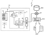
- FIG. 1 is a block diagram for explaining the overall configuration of an air conditioner management system 1 according to the embodiment.
- FIG. 2 is a diagram for explaining an example of the output voltage Va of the refrigerant sensor 13.
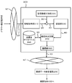
- FIG. 3 is a diagram for explaining the function of the external server 300.
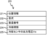
- FIG. 4 is a conceptual diagram for explaining an example of the device information 20 received by the information acquisition unit.
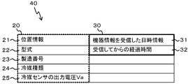
- FIG. 5 is a conceptual diagram for explaining the device information 40 after the management information 30 is added.
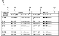
- FIG. 6 is a diagram for explaining an example of the transmission destination information 50. As shown in FIG.
- the air conditioner management system 1 includes an air conditioner 10, an external server 300 connected to the air conditioner 10 via a network line NT, a wireless data transmission / reception device 200, and a repair service. And a terminal device 400 owned by the person in charge.
- the air conditioner 10 includes an indoor unit 11, an outdoor unit 12, a refrigerant sensor 13, a GPS (Global Positioning System: positioning device) 14, and an output device 15.
- GPS Global Positioning System: positioning device
- the refrigerant R (substituting fluorocarbon gas) circulates between the indoor unit 11 installed indoors and the outdoor unit 12 installed outdoor, and heat exchange with the refrigerant R causes indoors. Cold air or warm air is blown from the machine 11.
- a slightly flammable refrigerant such as hydrofluorocarbon (HFC) R32 which is an alternative fluorocarbon is used.
- the indoor unit 11 is provided with a refrigerant sensor 13 for detecting the leakage of the refrigerant R in the indoor unit 11.
- a refrigerant sensor 13 is provided for the corresponding indoor unit 11, and the manufacturing number of the refrigerant sensor 13 and the manufacturing number of the indoor unit 11 are associated one-on-one.
- the refrigerant sensor 13 has a sensor unit (not shown) for detecting particles of the refrigerant R leaked into the air, and the amount of particles detected by the sensor unit (not shown) in the indoor unit 11 The leak of the refrigerant R is detected.
- the refrigerant sensor 13 outputs a voltage (output voltage Va) according to the amount of particles of the refrigerant R leaked into the air, and the refrigerant R leaks in the indoor unit 11.
- the output voltage Va becomes higher as D.sub.i increases (the broken line in FIG. 2).
- the output voltage Va rises (solid line in FIG. 2).
- a threshold voltage Vth for determining the necessity of maintenance due to leakage or deterioration with time of the refrigerant R is set.
- the output voltage Va of the refrigerant sensor 13 becomes higher than the threshold voltage Vth, it is determined that maintenance such as replacement or repair of the refrigerant sensor 13 is necessary.
- the output voltage Va of the refrigerant sensor 13 is measured at predetermined intervals (for example, four months).
- the air conditioner 10 is to be measured at the next second measurement timing (for example, 60 months) based on the output voltage Va measured at the first measurement timing (for example, 54 months after the start of operation) at a predetermined interval.
- the output voltage Va of the reference voltage becomes higher than the threshold voltage Vth, it is determined that maintenance due to deterioration with time of the refrigerant sensor 13 is necessary.
- the air conditioner 10 predicts the future output voltage Va based on the change rate of the past output voltage Va of the refrigerant sensor 13, and predicts the output voltage Va by the next measurement timing (second measurement timing).
- the threshold voltage Vth exceeds the threshold voltage Vth, it is determined that the maintenance of the refrigerant sensor 13 is necessary.
- the refrigerant sensor 13 is integrally provided with a GPS 14 for acquiring position information (information indicating an installation place) of the refrigerant sensor 13.
- the GPS 14 corresponds to a position information acquisition device.
- the position information of the refrigerant sensor 13 acquired by the GPS 14 is transmitted to the output device 15 as the apparatus information 20 together with the output voltage Va of the refrigerant sensor 13 and other information.
- the output device 15 is connected to the external server 300 through a network line NT such as the Internet or a telecommunication line such as a telephone line.
- the output device 15 transmits the device information 20 including the position information of the refrigerant sensor 13 and the output voltage Va to the external server 300 via the network line NT.
- the output device 15 includes the information related to the manufacturing number, model, and refrigerant type of the refrigerant sensor 13 in the device information 20 together with each information described above, and this device information 20 is transmitted to the external server 300 via the network line NT. Send to
- the output device 15 can obtain the installation timing information of the refrigerant sensor 13 and / or the information regarding the first energization timing of the refrigerant sensor 13 in combination with the position information of the refrigerant sensor 13 and the output voltage Va described above,
- the above information may be included in the device information 20 and transmitted to the external server 300 via the network line NT.
- the external server 300 includes an information acquisition unit 310 that acquires the device information 20 from the output device 15 of the air conditioner 10 and the device information 20 acquired by the information acquisition unit 310 of the air conditioner 10.
- a management information addition unit 320 for adding management information 30 related to management, a storage unit 330 for storing device information 40 after addition of the management information 30, and a transmission destination determination unit 340 for determining a transmission destination to which the device information 40 is transmitted.
- a transmission destination database 350, and a communication unit 360 for transmitting the device information 40 to the wireless data transmitting / receiving apparatus 200 via the network line NT.
- a central processing unit (CPU) (not shown) provided in the external server 300 executes a control program stored in a read only memory (ROM) to obtain an information acquisition unit described below.
- the functions of the management information addition unit 320, the storage unit 330, the transmission destination determination unit 340, the transmission destination database 350, and the communication unit 360 are realized.
- the information acquisition unit 310 receives the device information 20 including the position information 21 of the air conditioner 10 (refrigerant sensor 13) via the network line NT.
- the device information 20 includes position information 21 of the refrigerant sensor 13, type information 22 of the refrigerant sensor 13, manufacturing number information 23 of the refrigerant sensor 13, and type information 24 of the refrigerant R. , And output voltage information 25 of the refrigerant sensor 13.
- Position information 21 of the refrigerant sensor 13 is acquired by a GPS 14 provided integrally with the refrigerant sensor 13.
- the position information 21 includes plane coordinates of latitude and longitude of the refrigerant sensor 13 (indoor unit 11) and height coordinates of a height position of the refrigerant sensor 13 (indoor unit 11).
- the position information (installation location) of the indoor unit 11 can be acquired based on the position information 21 of the refrigerant sensor 13.
- the type information 22 of the refrigerant sensor 13 is identification information uniquely assigned to the refrigerant sensor 13, and the refrigerant sensor 13 can be identified based on the type information 22.
- a specific refrigerant sensor 13 can be specified from among the plurality of refrigerant sensors 13 by referring to the type information 22 of the refrigerant sensor 13.
- the indoor unit 11 can be identified based on the type information 22 of the refrigerant sensor 13.
- the serial number information 23 of the refrigerant sensor 13 is identification information uniquely assigned to the refrigerant sensor 13, and the refrigerant sensor 13 can be identified based on the serial number information 23.
- the indoor unit 11 can be identified based on the manufacturing number 23 of the refrigerant sensor 13.
- the refrigerant type information 24 stores the type of the refrigerant R used in the air conditioner 10.
- a slightly flammable refrigerant such as hydrofluorocarbon (HFC) R32 which is an alternative fluorocarbon is used.
- HFC hydrofluorocarbon
- R32 is stored in the refrigerant type information 24.
- the output voltage information 25 of the refrigerant sensor 13 is a voltage value (output voltage Va) output from the refrigerant sensor 13.
- the output voltage information 25 is measured by a voltmeter (not shown).
- the management information addition unit 320 adds management information 30 related to management of the air conditioner 10 to the device information 20 received by the information acquisition unit 310.
- date and time information 31 when the external server 300 receives the device information 20 (broken line in FIG. 5) from the air conditioner 10 and elapsed time from the date and time when the device information 20 is received And information 32 (thick solid line in FIG. 5).
- the management information 30 in addition to the date information 31 and the elapsed time information 32 described above, information regarding the date when the air conditioner 10 is first energized, or the information obtaining unit 310 obtains the device information 20 from the air conditioner 10. If it is possible to obtain information on the date and time of the event, at least one of these pieces of information may be included.
- the device information 40 after the management information addition unit 320 adds the management information 30 is temporarily stored in the storage unit 330.
- the storage unit 330 can apply, for example, a random access memory (RAM) that the external server 300 has.
- RAM random access memory
- the storage unit 330 When the storage unit 330 has the device information 40 already stored and the device information 40 scheduled to be newly stored, the storage unit 330 newly stores the manufacturing number information 23 and the model information 22 of the device information 40 already stored. If the serial number information 23 and the model information 22 of the device information 40 to be scheduled match, the device information 40 to be newly stored is stored (updated) in place of the device information 40 already stored.
- the device information 40 stored in the storage unit 330 is transmitted to the transmission destination determination unit 340 in response to a request from the transmission destination determination unit 340.
- the transmission destination determination unit 340 refers to the position information 21 of the device information 40 transmitted from the storage unit 330 and the transmission destination information 50 of the transmission destination database 350, and selects a repair service person who transmits the device information 40 decide.
- transmission destination information 50 of a person in charge of repair service who performs maintenance of the air conditioner 10 is stored (see FIG. 6).
- the transmission destination information 50 includes information such as the location 51 of the repair service person who transmits the device information 40, the names 52 and 53 of the person in charge, and the e-mail addresses 54 and 55.
- the destination information 50 is divided into the contact A, which is selected preferentially, and the contact B, which is selected next, and the person in charge of the contact B can not contact the person in charge of the contact A. Is selected.
- the transmission destination information 50 may include a phone number of a mobile phone held by a person in charge of repair service, or a URL (Uniform Resource Locator) indicating a location of a home page of a belonging company (branch, service company).
- URL Uniform Resource Locator
- the transmission destination determination unit 340 transmits, based on the position information 21 (FIG. 5) of the air conditioner 10 included in the device information 40, the person in charge of repair service present closest to the position information 21 to the transmission destination information 50 ( It selects from the location 51) of FIG. 6, and determines it as a mail destination.
- the communication unit 360 uses the mail address information 54 and 55 of the repair service representative determined by the transmission destination determination unit 340 to store the storage unit 330 for the terminal device 400 of the repair service representative.
- the stored device information 40 is transmitted.
- the external server 300 can transmit the device information 40 of the air conditioner 10 to the terminal device 400 of the person in charge of repair service closest to the installation location of the air conditioner 10 requiring maintenance.
- the repair service person in charge can refer to the device information 40 displayed on the terminal device 400 to accurately grasp the installation location of the air conditioner 10 (refrigerant sensor 13) requiring maintenance, etc. Maintenance can be performed efficiently.
- the repair service personnel can save time and labor for registering the installation date and time of the air conditioner 10, and can easily manage the air conditioner 10.
- the communication unit 360 may determine the maintenance time of the air conditioner 10 based on the management information 30 of the device information 40. As a result, the external server 300 automatically determines the maintenance time of the air conditioner 10. In the management system 1 of the air conditioner 10, this maintenance time is a terminal owned by the person in charge of the repair service together with the device information 40. It can be sent to the device 400.
- the GPS 14 may be a refrigerant sensor 13 and It may be separated, and may be provided in the indoor unit 11, and may be provided in the outdoor unit 12 (one-dot chain line in FIG. 1).
- GPS14 was used as a positional information acquisition apparatus as a positional information acquisition apparatus
- it is an apparatus and method which can acquire positional information, such as refrigerant sensor 13, it will be limited to this Instead, a wireless communication device, various position information acquisition devices using a wired communication device, and an acquisition method may be used.
- the transmission destination database 350 is provided accessible from the terminal device 400 outside the external server 300 via the communication unit 360, and the transmission destination information 50 stored in the transmission destination database 350 is updated from the terminal device 400. It may be possible.
- the new repair service person sends the information from the terminal device 400 to the destination.
- Information 50 can be updated directly. Therefore, in the management system 1 of the air conditioner 10, the transmission destination information 50 can always be easily updated to the latest information.
- FIG. 7 is a flowchart illustrating a method of managing the air conditioner 10.
- step S101 the information acquisition unit 310 of the external server 300 determines whether or not the device information 20 has been acquired from the air conditioner 10 (output device 15), and acquires the device information 20. When it determines with (step S101: YES), it progresses to step S102. If the information acquisition unit 310 determines that the device information 20 has not been acquired from the air conditioner 10 (step S101: NO), the determination process of step S101 is repeated until it is determined that the device information 20 has been acquired.
- the management information addition unit 320 includes, in the device information 20 acquired from the air conditioner 10, the date and time information when the air conditioner 10 was initially installed or the date and time information when the refrigerant sensor 13 is first energized. Determine if there is.
- step S102 determines that the device information 20 includes the information on the date and time described above (step S102: YES)
- the process proceeds to step S104, and the management information addition unit 320 determines that the information on the date and time is not included ( Step S102; NO) Go to Step S103.
- step S103 the management information adding unit 320 manages the date and time information 31 when the device information 20 is acquired from the air conditioner 10, and / or the management including the elapsed time 32 after the device information 20 is received from the air conditioner 10.
- the information 30 is added to the device information 20.
- step S104 the external server 300 temporarily stores the device information 40 after adding the management information 30 to the device information 20 in the storage unit 330. Further, in step S104, when the management information 30 is not added to the device information 20, the external server 300 temporarily stores the device information 20 as the device information 40 in the storage unit 330.
- step S 105 the transmission destination determination unit 340 performs device information based on the position information 21 of the device information 40 stored in the storage unit 330 and the location information 51 of the transmission destination information 50 stored in the transmission destination database 350. Select and determine a repair service representative to send 40.
- the transmission destination determination unit 340 selects a person in charge of repair service in the area closest to the installation location of the air conditioner 10 based on the position information 21 of the air conditioner 10 of the device information 40.
- the transmission destination determination unit 340 preferentially selects the repair service representative of the contact A from among the contact A and the contact B in the closest area. Then, if the repair service representative at contact A can not be contacted, the repair service representative at contact B is selected.
- step S106 the communication unit 360 transmits the device information 40 to which the management information 30 has been added to the e-mail address of the terminal device 400 owned by the person in charge of repair service selected in step S105, and the processing ends.
- the device information 40 including the position information 21 of the air conditioner 10 and the output voltage information 25 of the refrigerant sensor 13 is transmitted to the terminal device 400 of the repair service person closest to the air conditioner 10 requiring maintenance. Ru. Therefore, the repair service representative quickly confirms the necessity for maintenance of the air conditioner 10 and the installation location by checking the device information 40 (the position information 21 and the output voltage information 25) received by the terminal device 400. Maintenance of the air conditioner 10 can be performed quickly and efficiently.
- the date and time information 31 such as the date and time information 31 when the information acquisition unit 310 receives the device information 20 and elapsed time information 32 after reception is strictly hour and minute It may be recorded up to seconds or may be recorded in units of month and day.
- a management system of the air conditioner 10 wherein the information acquisition unit 310 acquires device information 20 including the position information 21 of the air conditioner 10 from the air conditioner 10, and the information acquisition unit 310 Communication to transmit the device information 40 after adding the management information 30 related to the management information 30 related to the management of the air conditioner 10 to the device information 20 and the device information 40 after adding the management information 30 to the outside of the air conditioner 10 And a unit 360.
- the management information 30 is added to the device information 20 including the position information 21 transmitted from the air conditioner 10, and the management information 30 is added.
- the device information 40 is transmitted to the outside. Therefore, in the management system 1 of the air conditioner 10, it is possible to easily manage the air conditioner 10 by omitting the time and effort of inputting information necessary for the maintenance of the air conditioner 10 in advance.
- the management information 30 related to the management of the air conditioner 10 is configured to be information regarding the date and time when the information acquisition unit 310 acquires the device information 20 from the air conditioner 10.
- the management system 1 of the air conditioner 10 can simplify the date information even when the device information 20 transmitted from the air conditioner 10 does not include the date and time information related to the management of the air conditioner 10.
- the maintenance period of the air conditioner 10 can be properly determined.
- the management information 30 related to the management of the air conditioner 10 is information on the date and time when the air conditioner 10 was first installed, or information on the date and time when the air conditioner 10 was first energized, It is set as at least any one.
- the air conditioning is performed based on the information on the date and time when the air conditioner 10 was first installed or the information on the date and time when the air conditioner 10 was first energized. Since the usage time of the machine 10 (the refrigerant sensor 13) is known, the maintenance time of the air conditioner 10 can be easily determined.
- the transmission destination database 350 for storing the transmission destination information 50 outside the air conditioner 10, and the transmission destination determination unit 340 for selecting and determining which one of the transmission destination information 50 is to be transmitted.
- the transmission destination determination unit 340 based on the position information 21 of the air conditioner 10 included in the device information 20, among the transmission destination information 50 stored in the transmission destination database 350, a predetermined transmission destination Were selected and decided.
- the transmission destination determination unit 340 selects and determines the transmission destination to which the device information 40 is to be transmitted based on the transmission destination information 50 of the transmission destination database 350 and the position information 21 included in the device information 20. Do. Therefore, the registration work of the transmission destination information 50 at the time of installation of the air conditioner 10 by the person in charge of repair service can be omitted, and maintenance of the air conditioner 10 can be performed quickly and efficiently.
- the transmission destination determination unit 340 preferentially selects and determines the transmission destination closest to the installation position of the air conditioner 10 among the plurality of transmission destination information 50, it is determined by the repair service person in emergency maintenance. It is possible to promptly carry out emergency maintenance.
- the management information addition unit 320 relates to the device information 20 acquired by the information acquisition unit 310, information on the date and time when the air conditioner 10 is first installed, and the date and time when the air conditioner 10 is first energized.
- date and time information 31 at which the information acquisition unit 310 acquires the device information 20 from the air conditioner 10 or an elapsed time 32 from the acquired date and time is added to the device information 20. .
- the management information addition unit 320 adds, to the device information 20, at least the date information 31 when the information acquisition unit 310 acquires the device information 20 from the air conditioner 10, or the elapsed time information 32 from the acquired date Therefore, the usage time of the air conditioner 10 can be easily grasped with a simple configuration. Therefore, the management system 1 of the air conditioner 10 can appropriately determine the maintenance time of the air conditioner 10 with a simple configuration.
- the device information 20 acquired by the information acquisition unit 310 includes at least one of the information on the serial number 23 or the model 22 of the air conditioner 10 in combination with the position information 21 of the air conditioner 10 It was set as including one.
- the management system 1 of the air conditioner 10 can reliably specify the air conditioner 10 based on the information on the serial number 23 or the type 22 uniquely assigned to the air conditioner 10. .
- the management system 1 of the air conditioner 10 has the storage unit 330 for storing the device information 40 acquired by the information acquisition unit 310, and the storage unit 330 has the serial number of the device information 40 already stored. If the information 23 or the type information 22 is identical to the serial number information 23 or the type information 22 of the device information 40 to be newly stored, it is to be newly stored instead of the device information 40 already stored. The device information 40 is stored.
- the air conditioner 10 when configured in this way, in the management system 1 of the air conditioner 10, for example, even if the installation location (position information 21) of the air conditioner 10 changes due to lease, etc., based on the information on the serial number 23 or model 22 Thus, the air conditioner 10 can be identified. Therefore, in the management system 1 of the air conditioner 10, the maintenance time of the air conditioner 10 when the installation position changes can be appropriately determined.
- the management system 1 of the air conditioner 10 has the communication unit 360 (notification unit) for transmitting (notifying) the maintenance time of the air conditioner 10 to the outside, and the communication unit 360 is the air conditioner 10
- the maintenance time of the air conditioner 10 is determined on the basis of the information on the date and time at which the air conditioner 10 was installed or the information on the date and time of the first energization.
- the person in charge of repair service can appropriately perform maintenance on the air conditioner 10 based on the determination result of the maintenance time transmitted from the communication unit 360.
- the transmission destination database 350 is configured to update the transmission destination information 50 stored in the transmission destination database 350 based on the updated transmission destination information 50 received from the outside of the external server 300.
- the new repair service representative can easily update the transmission destination information 50, and the new repair service representative can update the air conditioner 10 Maintenance can be performed reliably.
- FIG. 8 is a block diagram for explaining the overall configuration of a management system 1A of the air conditioner 10A according to the second embodiment.
- the air conditioner 10A includes the central control unit 16 that performs overall control of the air conditioner 10A, and the point that the central control unit 16 is provided with the GPS 14 is the aforementioned. It differs from the embodiment described above.
- the same components as those in the above-described embodiment are denoted by the same reference numerals and will be described as necessary.
- the air conditioner 10A is provided with a central control unit 16, and the central control unit 16 performs overall control of the indoor unit 11 and the outdoor unit 12 of the air conditioner 10A.
- the central control unit 16 individually controls the indoor units 11 and the outdoor unit 12 based on the indoor temperature and the set temperature.
- the centralized control device 16 can also determine from which indoor unit 11 the device information 20A including the output voltage Va of the refrigerant sensor 13 provided in the indoor unit 11 or the outdoor unit 12 is transmitted.
- the central control unit 16 is connected to the network line NT, and is connected to the external server 300 via the network line NT.
- the centralized control device 16 is provided with a GPS 14 and an output unit 161.
- the output unit 161 of the central control device 16 transmits the device information 20A including the position information of the central control device 16 acquired by the GPS 14 to the external server 300 via the network line NT.
- the management information 30 is added to the device information 20A transmitted from the output unit 161 of the central control device 16, and the device information 40A after the management information 30 is added is a terminal device 400 of the person in charge of repair service. Send to
- the choice for the repair service person in the external server 300 is the same as in the above-described embodiment, based on the location information of the device information 40A and the location of the transmission destination information, the area closest to the air conditioner 10A requiring maintenance. A repair service representative is selected and determined.
- the repair service representative accurately refers to the device information 40A including the position information of the central control device 16 transmitted to the terminal device 400 to accurately determine the presence / absence of the need for maintenance of the indoor unit 11 and the installation location. Can be grasped. Therefore, the repair service representative can perform maintenance of the air conditioner 10A quickly and efficiently.
- the air conditioner 10A includes the central control unit 16 (control unit) that controls the air conditioner 10A, and the GPS 14 (positional information acquisition unit) that acquires the positional information of the central control unit 16.
- the GPS 14 is provided in the central control unit 16.
- the centralized control device 16 includes the position information of the refrigerant sensor 13 by providing the centralized control unit 16 for individually controlling the plurality of indoor units 11. It can be determined from which indoor unit 11 (refrigerant sensor 13) or the outdoor unit 12 the device information 20A has been sent.
- the installation position of the central control unit 16 is acquired by the GPS 14, and the indoor unit 11 (refrigerant sensor 13) requiring maintenance or the outdoor unit 12 (refrigerant) by the central control unit 16
- the sensor 13 can be identified.
- the central control device 16 is configured to have the output unit 161 that outputs the device information 20A including the position information of the central control device 16 acquired by the GPS 14 to the external server 300 outside the air conditioner 10A. .
- the output unit 161 of the central control unit 16 can output the device information 20A including the position information of the central control unit 16 to the external server 300. There is no need to provide it separately, and the configuration of the air conditioner 10A can be simplified and the manufacturing cost can be reduced.
- the present invention is not limited to the one provided with all the configurations of the above-described embodiment, and a part of the configuration of the above-described embodiment is replaced with the configuration of the other embodiments. Alternatively, the configuration of the above-described embodiment may be replaced with the configuration of another embodiment.
- configuration, functions, processing, and means of the above-described embodiment may be realized by hardware, for example, by designing part or all of them with an integrated circuit.
- configurations and functions described above may be realized by execution of a program in which a processor realizes each function.
- the information such as this program can be stored in a storage device such as a memory.
- Air conditioning system 10: Air conditioner, 11: indoor unit, 12: outdoor unit, 13: refrigerant sensor, 14: GPS, 15: output device, 16: central control device, 161: output unit, 20: device Information 21: position information 22: type information 23: serial number 24: type information of refrigerant 25: output voltage of refrigerant sensor 30: management information 31: date and time information when device information is received Elapsed time from 40, device information 50, transmission destination information 200: wireless data transmission / reception device 300: external server 310: information acquisition unit 320: management information addition unit 330: storage unit 340: transmission destination determination Unit, 350: Destination database, 360: Communication unit, 400: Terminal device, NT: Network line, Va: Output voltage, Vth: Threshold voltage, R: Refrigerant
Landscapes
- Engineering & Computer Science (AREA)
- Chemical & Material Sciences (AREA)
- Combustion & Propulsion (AREA)
- Mechanical Engineering (AREA)
- General Engineering & Computer Science (AREA)
- Human Computer Interaction (AREA)
- Physics & Mathematics (AREA)
- Fuzzy Systems (AREA)
- Mathematical Physics (AREA)
- Signal Processing (AREA)
- Air Conditioning Control Device (AREA)
- Management, Administration, Business Operations System, And Electronic Commerce (AREA)
Abstract
空気調和機の設置場所などの情報を管理データベースに登録する手間を省き、空気調和機の管理を容易に行えるようにした空気調和機の管理システムを提供する。 空気調和機10の管理システムであって、空気調和機10から、当該空気調和機10の位置情報21を含む機器情報20を取得する情報取得部310と、情報取得部310で取得した機器情報20に、空気調和機10の管理に関連する管理情報30を付加する管理情報付加部320と、管理情報30を付加したのちの機器情報40を、空気調和機10の外部に送信する通信部360と、を有する構成とした。
Description
本発明は、空気調和機の管理システムおよび管理方法に関する。
近年、環境負荷を少なくするため、代替フロンガスを冷媒として用いた空気調和機が開発されている。このような冷媒として、例えば、ハイドロフルオロカーボン(HFC)類のR32などの微燃性冷媒が用いられる。
空気調和機に微燃性冷媒を用いた場合、微燃性冷媒の漏洩に起因した発火の恐れがある。このため、この種の空気調和機では、漏洩検出センサを用いて微燃性冷媒の漏洩を高精度に検知する必要がある。しかしながら、漏洩検知センサは、経時劣化や故障により検出精度が低下するため、定期的な交換、修理などのメンテナンスが必要になるという問題がある。
特許文献1には、複数の漏洩検知センサを設けた空気調和機が開示されている。
特許文献1に開示された空気調和機では、複数の漏洩検知センサを設けることで、何れかの漏洩検知センサが経時劣化や故障した場合でも、他の漏洩検知センサで微燃性冷媒の漏洩を検知できるため、漏洩検知センサの交換、修理などのメンテナンスの頻度を少なくすることができる。
しかしながら、特許文献1に開示された空気調和機では、複数の漏洩検知センサが同時に経時劣化や故障した場合、微燃性冷媒の漏洩を高精度に検出できない恐れがある。
また、この種の空気調和機では、空気調和機のメンテナンスに必要な情報を、データベースなどに予め入力しておかないと、空気調和機のメンテナンスの要否判断や、設置場所の正確な把握が難しい場合がある。よって、空気調和機のメンテナンスに必要な情報をデータベースに登録する手間がかかり、空気調和機の管理を適切に行い難いという問題がある。
したがって本発明は、上記課題に鑑みてなされたもので、空気調和機の管理システムでは、空気調和機のメンテナンスに必要な情報を予め入力する手間を省き、空気調和機の管理を容易に行えるようにした空気調和機の管理システムを提供することを目的とする。
上記課題を解決するため、空気調和機の管理システムであって、空気調和機から、当該空気調和機の位置情報を含む機器情報を取得する情報取得部と、情報取得部で取得した機器情報に、空気調和機の管理に関連する管理情報を付加する管理情報付加部と、管理情報を付加したのちの機器情報を、空気調和機の外部に送信する通信部と、を有する構成とした。
本発明によれば、空気調和機の管理システムでは、空気調和機のメンテナンスに必要な情報を予め入力する手間を省き、空気調和機の管理を容易に行えるようにした空気調和機の管理システムを提供することができる。
[空気調和機の管理システム]
以下、本発明の実施の形態にかかる空気調和機の管理システム1を説明する。
図1は、実施の形態にかかる空気調和機の管理システム1の全体構成を説明するブロック図である。
図2は、冷媒センサ13の出力電圧Vaの一例を説明する図である。
図3は、外部サーバ300の機能を説明する図である。
図4は、情報取得部が受信した機器情報20の一例を説明する概念図である。
図5は、管理情報30を付加された後の機器情報40を説明する概念図である。
図6は、送信先情報50の一例を説明する図である。
以下、本発明の実施の形態にかかる空気調和機の管理システム1を説明する。
図1は、実施の形態にかかる空気調和機の管理システム1の全体構成を説明するブロック図である。
図2は、冷媒センサ13の出力電圧Vaの一例を説明する図である。
図3は、外部サーバ300の機能を説明する図である。
図4は、情報取得部が受信した機器情報20の一例を説明する概念図である。
図5は、管理情報30を付加された後の機器情報40を説明する概念図である。
図6は、送信先情報50の一例を説明する図である。
図1に示すように、空気調和機の管理システム1は、空気調和機10と、ネットワーク回線NTを介して空気調和機10に接続された外部サーバ300と、無線データ送受信装置200と、修理サービス担当者が保有する端末機器400とを有している。
[空気調和機]
図1に示すように、空気調和機10は、室内機11と、室外機12と、冷媒センサ13と、GPS(Global Positioning System:測位装置)14と、出力装置15とを有している。
図1に示すように、空気調和機10は、室内機11と、室外機12と、冷媒センサ13と、GPS(Global Positioning System:測位装置)14と、出力装置15とを有している。
空気調和機10では、室内に設置された室内機11と、室外に設置された室外機12との間で、冷媒R(代替フロンガス)が循環しており、この冷媒Rとの熱交換により室内機11から冷風又は温風が吹き出されるようになっている。実施の形態では、冷媒Rとして、代替フロンのハイドロフルオロカーボン(HFC)類のR32などの微燃性冷媒が用いられる。
室内機11には、当該室内機11における冷媒Rの漏洩を検知するための冷媒センサ13が設けられている。冷媒センサ13は対応する室内機11に対して1つ設けられており、冷媒センサ13の製造番号と室内機11の製造番号とは一対一で関連付けられている。
冷媒センサ13は、空気中に漏洩した冷媒Rの粒子を検知するセンサ部(図示せず)を有しており、このセンサ部(図示せず)で検知した粒子の量により室内機11での冷媒Rの漏洩を検知する。
図2に示すように、冷媒センサ13は、空気中に漏洩した冷媒Rの粒子の量に応じた電圧(出力電圧Va)を出力するようになっており、室内機11での冷媒Rの漏洩が多くなるほど出力電圧Vaが高くなる(図2の破線)。また、冷媒センサ13では、センサ部(図示せず)の経時劣化が進むに連れて出力電圧Vaが上昇する(図2の実線)。
空気調和機10では、冷媒Rの漏洩又は経時劣化によるメンテナンス要否判断の閾値電圧Vthが設定されている。空気調和機10では、冷媒センサ13の出力電圧Vaが、この閾値電圧Vthを超えて高くなると、冷媒センサ13の交換、修理などのメンテナンスが必要と判断する。
空気調和機10では、冷媒センサ13の出力電圧Vaを、所定の間隔(例えば、4カ月)ごとに計測している。空気調和機10では、所定の間隔における第1計測タイミング(例えば、運転開始後54カ月)で計測した出力電圧Vaに基づいて、次回の第2計測タイミング(例えば、60カ月)で計測される予定の出力電圧Vaが、閾値電圧Vthを超えて高くなると判定した場合、冷媒センサ13の経時劣化によるメンテナンスが必要と判定する。
つまり、空気調和機10は、冷媒センサ13の過去の出力電圧Vaの変化率に基づいて、将来の出力電圧Vaを予測し、次回の計測タイミング(第2計測タイミング)までに予測した出力電圧Vaが閾値電圧Vthを超えると判定した場合、冷媒センサ13のメンテナンスが必要と判定する。
図1に戻って、冷媒センサ13には、当該冷媒センサ13の位置情報(設置場所を示す情報)を取得するGPS14が一体的に設けられている。このGPS14は、位置情報取得装置に相当する。
GPS14で取得された冷媒センサ13の位置情報は、冷媒センサ13の出力電圧Va及びその他の情報と共に、機器情報20として出力装置15に送信される。
出力装置15は、インターネットなどのネットワーク回線NT又は、電話回線などの電気通信回線を通じて、外部サーバ300に接続されている。出力装置15は、冷媒センサ13の位置情報と出力電圧Vaを含む機器情報20を、ネットワーク回線NTを介して外部サーバ300に送信する。
また、出力装置15は、前述した各情報と合わせて、冷媒センサ13の製造番号、型式、冷媒種類に関する情報を機器情報20に含め、この機器情報20を、ネットワーク回線NTを介して外部サーバ300に送信する。
なお、出力装置15は、前述した冷媒センサ13の位置情報及び出力電圧Vaと合わせて、冷媒センサ13の設置時期情報、及び/又は冷媒センサ13の最初の通電時期に関する情報を取得できる場合、これらの情報を機器情報20に含め、ネットワーク回線NTを介して外部サーバ300に送信してもよい。
[外部サーバ]
図3に示すように、外部サーバ300は、空気調和機10の出力装置15から機器情報20を取得する情報取得部310と、情報取得部310が取得した機器情報20に、空気調和機10の管理に関する管理情報30を付加する管理情報付加部320と、管理情報30を付加したのちの機器情報40を記憶する記憶部330と、機器情報40を送信する送信先を決定する送信先決定部340と、送信先データベース350と、ネットワーク回線NTを介して、機器情報40を無線データ送受信装置200に送信する通信部360とを有する。
図3に示すように、外部サーバ300は、空気調和機10の出力装置15から機器情報20を取得する情報取得部310と、情報取得部310が取得した機器情報20に、空気調和機10の管理に関する管理情報30を付加する管理情報付加部320と、管理情報30を付加したのちの機器情報40を記憶する記憶部330と、機器情報40を送信する送信先を決定する送信先決定部340と、送信先データベース350と、ネットワーク回線NTを介して、機器情報40を無線データ送受信装置200に送信する通信部360とを有する。
外部サーバ300では、この外部サーバ300に設けられた図示しないCPU(Central Processing Unit)が、図示しないROM(Read Only Memory)に記憶された制御プログラムを実行することで、以下で説明する情報取得部310と、管理情報付加部320と、記憶部330と、送信先決定部340と、送信先データベース350と、通信部360との機能が実現される。
情報取得部310は、ネットワーク回線NTを介して空気調和機10(冷媒センサ13)の位置情報21を含む機器情報20を受信する。
ここで、図4に示すように、機器情報20は、冷媒センサ13の位置情報21と、冷媒センサ13の型式情報22と、冷媒センサ13の製造番号情報23と、冷媒Rの種類情報24と、冷媒センサ13の出力電圧情報25と、を含んでいる。
冷媒センサ13の位置情報21は、冷媒センサ13に一体的に設けられたGPS14により取得される。位置情報21は、冷媒センサ13(室内機11)の緯度、経度の平面座標と、冷媒センサ13(室内機11)の高さ位置の高低座標とを含んで構成される。
実施の形態では、冷媒センサ13は、室内機11に対応して設けられているため、この冷媒センサ13の位置情報21に基づいて、室内機11の位置情報(設置場所)を取得できる。
冷媒センサ13の型式情報22は、冷媒センサ13に固有に付された識別情報であり、この型式情報22に基づいて冷媒センサ13を特定できる。例えば、複数の冷媒センサ13を有する空気調和機10である場合、冷媒センサ13の型式情報22を参照することで、複数の冷媒センサ13の中から特定の冷媒センサ13を特定できる。
実施の形態では、冷媒センサ13は、室内機11に対応して設けられているため、冷媒センサ13の型式情報22に基づいて、室内機11を特定できる。
冷媒センサ13の製造番号情報23は、冷媒センサ13に固有に付された識別情報であり、この製造番号情報23に基づいて冷媒センサ13を特定できる。なお、冷媒センサ13は、室内機11内に設けられているため、冷媒センサ13の製造番号23に基づいて、室内機11を特定できる。
冷媒種類情報24は、空気調和機10で用いられる冷媒Rの種類が記憶されている。実施の形態では、冷媒Rとして、代替フロンのハイドロフルオロカーボン(HFC)類のR32などの微燃性冷媒が用いられる。この場合、冷媒種類情報24には、R32が記憶される。
冷媒センサ13の出力電圧情報25は、冷媒センサ13から出力された電圧値(出力電圧Va)である。出力電圧情報25は、電圧計(図示せず)で計測される。
図3に戻って、管理情報付加部320は、情報取得部310が受信した機器情報20に、空気調和機10の管理に関する管理情報30を付加する。
図5に示すように、管理情報30として、外部サーバ300が空気調和機10から機器情報20(図5の破線部)を受信した日時情報31と、機器情報20を受信した日時からの経過時間情報32とを含んでいる(図5の太実線部)。
また、管理情報30として、前述した日時情報31や経過時間情報32のほか、空気調和機10が最初に通電された日時に関する情報、または情報取得部310が空気調和機10から機器情報20を取得した日時に関する情報を取得できる場合、これらの情報のうち、少なくとも何れか一つを含んでいてもよい。
図3に戻って、管理情報付加部320により管理情報30が付加された後の機器情報40は、記憶部330に一時的に記憶される。記憶部330は、外部サーバ300が有するRAM(Random Access Memory)などを適用できる。
記憶部330は、既に記憶された機器情報40と、新たに記憶される予定の機器情報40とがある場合、既に記憶された機器情報40の製造番号情報23や型式情報22と、新たに記憶される予定の機器情報40の製造番号情報23や型式情報22とが一致する場合、既に記憶された機器情報40に代わって、新たに記憶される予定の機器情報40を記憶(更新)する。
記憶部330に記憶された機器情報40は、送信先決定部340からの求めに応じて当該送信先決定部340に送信される。
送信先決定部340は、記憶部330から送信された機器情報40の位置情報21と、送信先データベース350の送信先情報50とを参照し、機器情報40を送信する修理サービス担当者を選択及び決定する。
送信先データベース350には、空気調和機10のメンテナンスを行う修理サービス担当者の送信先情報50が記憶されている(図6参照)。
図6に示すように、送信先情報50には、機器情報40を送信する修理サービス担当者の所在地51、担当者名52、53、メールアドレス54、55などの情報が含まれている。送信先情報50は、優先的に選択される連絡先Aと、次に選択される連絡先Bとに区分けされており、連絡先Aの担当者に連絡が取れない場合に連絡先Bの担当者が選択される。
なお、送信先情報50には、修理サービス担当者の保有する携帯電話の電話番号や所属会社(支店、サービス会社)のホームページの場所を示すURL(Uniform Resource Locator)を含んでもよい。
送信先決定部340は、機器情報40に含まれる空気調和機10の位置情報21(図5)に基づいて、当該位置情報21に最も近い場所に存在する修理サービス担当者を送信先情報50(図6の所在地51)から選択し、メールの送信先として決定する。
図3に戻って、通信部360は、送信先決定部340で決定した修理サービス担当者のメールアドレス情報54、55を用いて、修理サービス担当者の端末機器400に対して、記憶部330に記憶された機器情報40を送信する。
これにより、外部サーバ300が、メンテナンスが必要な空気調和機10の設置場所に最も近い修理サービス担当者の端末機器400に対して、空気調和機10の機器情報40を送信することができる。修理サービス担当者は、端末機器400に表示された機器情報40を参照して、メンテナンスが必要な空気調和機10(冷媒センサ13)の設置場所などを正確に把握することができ、冷媒センサ13のメンテナンスを効率よく行うことができる。
また、修理サービス担当者が、空気調和機10の設置日時を登録する手間が省け、空気調和機10の管理を容易に行うことができる。
なお、通信部360が、機器情報40の管理情報30に基づいて空気調和機10のメンテナンス時期を判定するようにしてもよい。これにより、外部サーバ300側で、空気調和機10のメンテナンス時期の判断を自動で行い、空気調和機10の管理システム1では、このメンテナンス時期を、機器情報40と共に修理サービス担当者の保有する端末機器400に送信することができる。
なお、前述した実施の形態では、GPS14は、冷媒センサ13に一体的に設けられている場合を例示して説明したが、これに限定されるものではない、例えば、GPS14は、冷媒センサ13と分離して、室内機11に設けられていてもよく、また、室外機12に設けられていてもよい(図1の一点鎖線)。
また、前述した実施の形態では、位置情報取得装置としてGPS14を用いた場合を例示して説明したが、冷媒センサ13などの位置情報を取得できる装置、方法であればこれに限定されるものではなく、無線通信装置、有線通信装置を用いた様々な位置情報取得装置、取得方法であってもよい。
また、送信先データベース350は、通信部360を介して、外部サーバ300の外部の端末機器400からアクセス可能に設け、この送信先データベース350に記憶された送信先情報50を、端末機器400から更新できるようにしてもよい。
このように構成すると、修理サービス担当者の変更により、修理サービス担当者の所在地やメールアドレスなどの送信先情報50の内容が変わった場合、新たな修理サービス担当者は、端末機器400から送信先情報50を直接更新することができる。よって、空気調和機10の管理システム1では、送信先情報50を常に最新の情報に容易に更新することができる。
[空気調和機の管理方法]
次に、空気調和機10の管理方法を説明する。
次に、空気調和機10の管理方法を説明する。
図7は、空気調和機10の管理方法を説明するフローチャートである。
図7に示すように、ステップS101において、外部サーバ300の情報取得部310は、空気調和機10(出力装置15)から機器情報20を取得したか否かを判定し、機器情報20を取得したと判定した場合(ステップS101:YES)、ステップS102に進む。情報取得部310は、空気調和機10から機器情報20を取得していないと判定した場合(ステップS101:NO)、機器情報20を取得したと判定するまでステップS101の判定処理を繰り返す。
ステップS102において、管理情報付加部320は、空気調和機10から取得した機器情報20に、空気調和機10を最初に設置した日時情報、又は冷媒センサ13に最初に通電した日時情報が含まれているか否かを判定する。
管理情報付加部320は、機器情報20に前述した日時に関する情報が含まれていると判定した場合(ステップS102:YES)、ステップS104に進み、日時に関する情報が含まれていないと判定した場合(ステップS102;NO)、ステップS103に進む。
ステップS103において、管理情報付加部320は、機器情報20を空気調和機10から取得した日時情報31、又は/及び機器情報20を空気調和機10から受信してからの経過時間32などを含む管理情報30を、機器情報20に付加する。
ステップS104において、外部サーバ300では、機器情報20に管理情報30を付加した後の機器情報40を記憶部330に一時的に記憶する。また、ステップS104において、外部サーバ300では、機器情報20に管理情報30を付加しない場合、機器情報20を機器情報40として記憶部330に一時的に記憶する。
ステップS105において、送信先決定部340は、記憶部330に記憶された機器情報40の位置情報21と、送信先データベース350に記憶された送信先情報50の所在地情報51とに基づいて、機器情報40を送信する修理サービス担当者を選択及び決定する。
送信先決定部340は、機器情報40の空気調和機10の位置情報21に基づいて、この空気調和機10の設置場所に最も近い地域の修理サービス担当者を選択する。送信先決定部340は、最も近い地域の連絡先Aと連絡先Bのうち、優先して連絡先Aの修理サービス担当者を選択する。そして、連絡先Aの修理サービス担当者に連絡が取れない場合などには、連絡先Bの修理サービス担当者を選択する。
ステップS106において、通信部360は、管理情報30を付加した後の機器情報40を、ステップS105で選択した修理サービス担当者が保有する端末機器400のメールアドレスなどに送信して処理を終了する。
これにより、メンテナンスが必要な空気調和機10に最も近い修理サービス担当者の端末機器400に、空気調和機10の位置情報21や冷媒センサ13の出力電圧情報25が含まれる機器情報40が送信される。よって、修理サービス担当者は、端末機器400で受信した機器情報40(位置情報21や出力電圧情報25)を確認することで、空気調和機10のメンテナンスの必要性や設置場所を迅速に確認することができ、空気調和機10のメンテナンスを迅速、かつ効率よく行うことができる。
なお、前述した機器情報20に付加する管理情報30において、情報取得部310が機器情報20を受信した日時情報31や、受信してからの経過時間情報32などの日時情報は、厳密に時分秒まで記録してもよく、月日の単位で記録してもよい。
以上説明した通り、実施の形態では、
(1)空気調和機10の管理システムであって、空気調和機10から、当該空気調和機10の位置情報21を含む機器情報20を取得する情報取得部310と、情報取得部310で取得した機器情報20に、空気調和機10の管理に関連する管理情報30を付加する管理情報付加部320と、管理情報30を付加したのちの機器情報40を、空気調和機10の外部に送信する通信部360と、を有する構成とした。
(1)空気調和機10の管理システムであって、空気調和機10から、当該空気調和機10の位置情報21を含む機器情報20を取得する情報取得部310と、情報取得部310で取得した機器情報20に、空気調和機10の管理に関連する管理情報30を付加する管理情報付加部320と、管理情報30を付加したのちの機器情報40を、空気調和機10の外部に送信する通信部360と、を有する構成とした。
このように構成すると、空気調和機10の管理システム1では、空気調和機10から送信された位置情報21を含む機器情報20に管理情報30を付加すると共に、この管理情報30を付加した後の機器情報40を外部に送信する。よって、空気調和機10の管理システム1では、空気調和機10のメンテナンスに必要な情報を予め入力する手間を省き、空気調和機10の管理を容易に行える。
(2)また、空気調和機10の管理に関連する管理情報30は、情報取得部310が空気調和機10から機器情報20を取得した日時に関する情報である構成とした。
このように構成すると、空気調和機10の管理システム1は、空気調和機10から送信された機器情報20に空気調和機10の管理に関する日時情報が含まれていない場合でも、日付情報を簡易的に付加することができ、空気調和機10のメンテナンス時期を適切に判断することができる。
(3)また、空気調和機10の管理に関連する管理情報30は、空気調和機10が最初に設置された日時に関する情報、又は空気調和機10が最初に通電された日時に関する情報のうち、少なくとも何れか一つである構成とした。
このように構成すると、空気調和機10の管理システム1では、空気調和機10が最初に設置された日時に関する情報、又は空気調和機10が最初に通電された日時に関する情報に基づいて、空気調和機10(冷媒センサ13)の使用時間が分かるので、空気調和機10のメンテナンス時期の判定を容易に行うことができる。
(4)また、空気調和機10の外部の送信先情報50を記憶する送信先データベース350と、送信先情報50のうち、何れの送信先に送信するかを選択および決定する送信先決定部340と、を有し、送信先決定部340は、機器情報20に含まれる空気調和機10の位置情報21に基づいて、送信先データベース350に記憶された送信先情報50のうち、所定の送信先を選択および決定する構成とした。
このように構成すると、送信先決定部340が、送信先データベース350の送信先情報50と、機器情報20に含まれる位置情報21とに基づいて、機器情報40を送信する送信先の選択及び決定行う。よって、修理サービス担当者による空気調和機10の設置時の送信先情報50の登録作業を省略することができ、空気調和機10のメンテナンスを迅速、かつ効率よく行うことができる。
また、送信先決定部340は、複数の送信先情報50のうち、空気調和機10の設置位置に最も近い送信先を優先的に選択及び決定するので、緊急メンテナンス時において、修理サービス担当者による緊急メンテナンス対応を迅速に行うことが可能となる。
(5)また、管理情報付加部320は、情報取得部310で取得した機器情報20に、空気調和機10が最初に設置された日時に関する情報、空気調和機10が最初に通電された日時に関する情報の何れも含まれていない場合、情報取得部310が空気調和機10から機器情報20を取得した日時情報31、又は取得した日時からの経過時間32を、機器情報20に付加する構成とした。
このように構成すると、管理情報付加部320により、機器情報20に少なくとも情報取得部310が空気調和機10から機器情報20を取得した日時情報31、又は取得した日時からの経過時間情報32を付加するので、空気調和機10の使用時間を簡単な構成で簡易的に把握することができる。よって、空気調和機10の管理システム1は、空気調和機10のメンテナンス時期を簡単な構成で適切に判定することができる。
(6)また、情報取得部310で取得した機器情報20には、空気調和機10の位置情報21と合わせて、空気調和機10の製造番号23または型式22に関する情報のうち、少なくも何れか一つを含む構成とした。
このように構成すると、空気調和機10の管理システム1では、空気調和機10に固有に付与された製造番号23、又は型式22に関する情報に基づいて空気調和機10を確実に特定することができる。
(7)また、空気調和機10の管理システム1では、情報取得部310で取得した機器情報40を記憶する記憶部330を有し、記憶部330は、既に記憶された機器情報40の製造番号情報23または型式情報22と、新たに記憶する予定の機器情報40の製造番号情報23または型式情報22とが同一である場合、既に記憶された機器情報40に代えて、新たに記憶する予定の機器情報40を記憶する構成とした。
このように構成すると、空気調和機10の管理システム1では、例えば、リース等で空気調和機10の設置場所(位置情報21)が変わった場合でも、製造番号23、又は型式22に関する情報に基づいて空気調和機10を特定することができる。よって、空気調和機10の管理システム1では、設置位置が変わった場合の空気調和機10のメンテナンス時期を適切に判断することができる。
(8)また、空気調和機10の管理システム1は、空気調和機10のメンテナンス時期を外部に送信(報知)する通信部360(報知部)を有し、通信部360は、空気調和機10が設置された日時に関する情報、または最初に通電された日時に関する情報に基づいて、空気調和機10のメンテナンス時期を判断する構成とした。
このように構成すると、修理サービス担当者は、通信部360から送信されたメンテナンス時期の判断結果に基づいて、空気調和機10のメンテナンスを適切に行うことができる。
(9)また、送信先データベース350は、外部サーバ300の外部から受信した更新送信先情報50に基づいて、当該送信先データベース350に記憶された送信先情報50を更新する構成とした。
このように構成すると、修理サービス担当者の送信先情報50が変わった場合、新たな修理サービス担当者による送信先情報50の更新を容易に行え、新たな修理サービス担当者による空気調和機10のメンテナンスを確実に行うことができる。
[第2の実施の形態]
次に、第2の実施の形態にかかる空気調和機10Aの管理システム1Aを説明する。
次に、第2の実施の形態にかかる空気調和機10Aの管理システム1Aを説明する。
図8は、第2の実施の形態にかかる空気調和機10Aの管理システム1Aの全体構成を説明するブロック図である。
第2の実施の形態にかかる空気調和機10Aは、当該空気調和機10Aの全体制御を行う集中制御装置16を有しており、この集中制御装置16にGPS14が設けられている点が、前述した実施の形態と異なる。なお、前述した実施の形態と同じ構成については、同一の符号を付し、必要に応じて説明する。
図8に示すように、空気調和機10Aには集中制御装置16が設けられており、この集中制御装置16により、空気調和機10Aの室内機11及び室外機12の全体制御が行われる。
また、複数の室内機11を有する空気調和機10Aである場合、集中制御装置16は、室内温度や設定温度に基づいて、各々の室内機11及び室外機12を個別に制御する。また、集中制御装置16は、室内機11又は室外機12に設けられた冷媒センサ13の出力電圧Vaを含む機器情報20Aが、どの室内機11から送信されたものかを判定することができる。
集中制御装置16は、ネットワーク回線NTに接続されており、このネットワーク回線NTを介して外部サーバ300に接続されている。
集中制御装置16には、GPS14と、出力部161とが設けられている。集中制御装置16の出力部161は、GPS14で取得した集中制御装置16の位置情報を含む機器情報20Aを、ネットワーク回線NTを介して外部サーバ300に送信する。
外部サーバ300では、集中制御装置16の出力部161から送信された機器情報20Aに管理情報30を付加すると共に、管理情報30を付加した後の機器情報40Aを、修理サービス担当者の端末機器400に送信する。
外部サーバ300における修理サービス担当者に選択は、前述した実施の形態と同様に、機器情報40Aの位置情報と、送信先情報の所在地に基づいて、メンテナンスの必要な空気調和機10Aに最も近い地域の修理サービス担当者が選択及び決定される。
これにより、修理サービス担当者は、端末機器400に送信された集中制御装置16の位置情報を含む機器情報40Aを参照することで、室内機11のメンテナンスの必要性の有無や、設置場所を正確に把握することができる。よって、修理サービス担当者は、空気調和機10Aのメンテナンスを迅速、かつ効率よく行うことができる。
以上説明した通り、第2の実施の形態では、
(10)空気調和機10Aは、この空気調和機10Aを制御する集中制御装置16(制御装置)と、この集中制御装置16の位置情報を取得するGPS14(位置情報取得装置)と、を有し、GPS14は、集中制御装置16に設けられる構成とした。
(10)空気調和機10Aは、この空気調和機10Aを制御する集中制御装置16(制御装置)と、この集中制御装置16の位置情報を取得するGPS14(位置情報取得装置)と、を有し、GPS14は、集中制御装置16に設けられる構成とした。
空気調和機10Aでは、複数の室内機11を有する構成である場合、複数の室内機11を個別に制御する集中制御装置16を設けることで、集中制御装置16により冷媒センサ13の位置情報を含む機器情報20Aが、どの室内機11(冷媒センサ13)又は室外機12から送信されてきたのか判定することができる。
このように構成すると、空気調和機10Aでは、集中制御装置16の設置位置をGPS14により取得すると共に、集中制御装置16により、メンテナンスが必要な室内機11(冷媒センサ13)又は室外機12(冷媒センサ13)を特定することができる。また、GPS14を複数の室内機11の全ての設ける必要がなく、空気調和機10の構成を簡略化することができると共に、製造コストを抑えることができる。
(11)また、集中制御装置16は、GPS14で取得した集中制御装置16の位置情報を含む機器情報20Aを、空気調和機10Aの外部の外部サーバ300に出力する出力部161を有する構成とした。
このように構成すると、空気調和機10Aでは、集中制御装置16が有する出力部161により、集中制御装置16の位置情報を含む機器情報20Aを外部サーバ300に出力できるので、前述した出力装置15を別途設ける必要がなく、空気調和機10Aの構成を簡略化することができると共に、製造コストを抑えることができる。
また、本発明は、前述した実施の形態の全ての構成を備えているものに限定されるものではなく、前述した実施の形態の構成の一部を、他の実施の形態の構成に置き換えてもよく、また、前述した実施の形態の構成を、他の実施の形態の構成に置き換えてもよい。
また、前述した実施の形態の一部の構成について、他の実施の形態の構成に追加、削除、置換をしてもよい。
また、上記した実施の形態の構成、機能、処理、手段は、それの一部又は全部を、例えば、集積回路で設計する等により、ハードウェアで実現してもよい。また、前述した構成、機能は、プロセッサがそれぞれの機能を実現するプログラムの実行により実現できるものであってもよい。
このプログラム等の情報は、メモリなどの記憶装置に記憶しておくことができる。
このプログラム等の情報は、メモリなどの記憶装置に記憶しておくことができる。
1:空気調和システム、10:空気調和機、11:室内機、12:室外機、13:冷媒センサ、14:GPS、15:出力装置、16:集中制御装置、161:出力部、20:機器情報、21:位置情報、22:型式情報、23:製造番号、24:冷媒の種類情報、25:冷媒センサの出力電圧、30:管理情報、31:機器情報を受信した日時情報、受信してからの経過時間、40機器情報、50:送信先情報、200:無線データ送受信装置、300:外部サーバ、310:情報取得部、320:管理情報付加部、330:記憶部、340:送信先決定部、350:送信先データベース、360:通信部、400:端末機器、NT:ネットワーク回線、Va:出力電圧、Vth:閾値電圧、R:冷媒
Claims (15)
- 空気調和機の管理システムであって、
前記空気調和機から、当該空気調和機の位置情報を含む機器情報を取得する情報取得部と、
前記情報取得部で取得した前記機器情報に、前記空気調和機の管理に関連する管理情報を付加する管理情報付加部と、
前記管理情報を付加したのちの前記機器情報を、前記空気調和機の外部に送信する通信部と、を有する空気調和機の管理システム。 - 前記空気調和機の管理に関連する管理情報は、前記情報取得部が前記空気調和機から前記所定の情報を取得した日時に関する情報である請求項1に記載の空気調和機の管理システム。
- 前記空気調和機の管理に関連する管理情報は、前記空気調和機が最初に設置された日時に関する情報、又は前記空気調和機が最初に通電された日時に関する情報のうち、少なくとも何れか一つである請求項1に記載の空気調和機の管理システム。
- 前記空気調和機の外部の送信先情報を記憶する送信先データベースと、
前記送信先情報のうち、何れの送信先に送信するかを選択および決定する送信先決定部と、を有し、
前記送信先決定部は、前記機器情報に含まれる前記空気調和機の位置情報に基づいて、前記送信先データベースに記憶された前記送信先情報のうち、所定の送信先を選択および決定する請求項2または請求項3に記載の空気調和機の管理システム。 - 前記管理情報付加部は、前記情報取得部で取得した前記所定の情報に、前記空気調和機が最初に設置された日時に関する情報、前記空気調和機が最初に通電された日時に関する情報の何れも含まれていない場合、前記情報取得部が前記空気調和機から前記所定の情報を取得した日時に関する情報を、前記機器情報に付加する請求項4に記載の空気調和機の管理システム。
- 前記情報取得部で取得した前記機器情報には、前記空気調和機の前記位置情報と合わせて、前記空気調和機の製造番号または型式に関する情報のうち、少なくも何れか一つを含む請求項5に記載の空気調和機の管理システム。
- 前記情報取得部で取得した前記機器情報を記憶する記憶部を有し、
前記記憶部は、既に記憶された機器情報の製造番号または型式に関する情報と、新たに記憶する別の機器情報の製造番号または型式に関する情報とが同一である場合、前記既に記憶された機器情報に代えて、前記別の機器情報を記憶する請求項6に記載の空気調和機の管理システム。 - 前記空気調和機のメンテナンス時期を報知する報知部を有し、
前記報知部は、前記空気調和機が設置された日時に関する情報、または最初に通電された日時に関する情報に基づいて、前記空気調和機のメンテナンス時期を判断する請求項3に記載の空気調和機の管理システム。 - 前記送信先データベースは、前記外部サーバの外部から受信した更新送信先情報に基づいて、当該送信先データベースに記憶された前記送信先情報を更新する請求項4に記載の空気調和機の管理システム。
- 前記空気調和機は、当該空気調和機を制御する制御装置と、
当該制御装置の位置情報を取得する位置情報取得装置と、を有し、
前記位置情報取得装置は、前記制御装置に設けられる請求項1に記載の空気調和機の管理システム。 - 前記制御装置は、前記位置情報取得装置で取得した前記制御装置の前記位置情報を含む前記機器情報を、前記空気調和機の外部に出力する出力部を有する請求項10に記載の空気調和機の管理システム。
- 空気調和機の管理方法であって、
前記空気調和機から、当該空気調和機の位置情報を含む機器情報を取得する情報取得ステップと、
前記情報取得ステップで取得した前記機器情報に、前記空気調和機の管理に関連する日時情報を付加する管理情報付加ステップと、
前記管理情報を付加したのちの前記機器情報を、前記空気調和機の外部に送信する通信ステップと、を有する空気調和機の管理方法。 - 前記空気調和機の管理に関連する日時情報は、前記情報取得部が前記空気調和機から前記機器情報を取得した日時に関する情報である請求項12に記載の空気調和機の管理方法。
- 前記空気調和機の管理に関連する日時情報は、前記空気調和機が最初に設置された日時に関する情報、前記空気調和機が最初に通電された日時に関する情報のうち、少なくとも何れか一つである請求項12に記載の空気調和機の管理方法。
- 前記空気調和機の外部の送信先情報を記憶する送信先情報データベースと、
前記送信先情報のうち、何れの送信先に送信するかを選択および決定する送信先決定ステップと、を有し、
前記送信先決定ステップは、前記機器情報に含まれる前記空気調和機の位置情報に基づいて、前記送信先データベースに記憶されている前記送信先情報のうち、所定の送信先を選択および決定する請求項12に記載の空気調和機の管理方法。
Priority Applications (1)
| Application Number | Priority Date | Filing Date | Title |
|---|---|---|---|
| PCT/JP2017/046809 WO2019130453A1 (ja) | 2017-12-26 | 2017-12-26 | 空気調和機の管理システムおよび管理方法 |
Applications Claiming Priority (1)
| Application Number | Priority Date | Filing Date | Title |
|---|---|---|---|
| PCT/JP2017/046809 WO2019130453A1 (ja) | 2017-12-26 | 2017-12-26 | 空気調和機の管理システムおよび管理方法 |
Publications (1)
| Publication Number | Publication Date |
|---|---|
| WO2019130453A1 true WO2019130453A1 (ja) | 2019-07-04 |
Family
ID=67063299
Family Applications (1)
| Application Number | Title | Priority Date | Filing Date |
|---|---|---|---|
| PCT/JP2017/046809 Ceased WO2019130453A1 (ja) | 2017-12-26 | 2017-12-26 | 空気調和機の管理システムおよび管理方法 |
Country Status (1)
| Country | Link |
|---|---|
| WO (1) | WO2019130453A1 (ja) |
Citations (3)
| Publication number | Priority date | Publication date | Assignee | Title |
|---|---|---|---|---|
| JP2011226694A (ja) * | 2010-04-19 | 2011-11-10 | Mitsubishi Electric Corp | 空気調和機、機器システム、情報管理システム、空気調和機の制御方法 |
| JP2017107466A (ja) * | 2015-12-11 | 2017-06-15 | ダイキン工業株式会社 | 情報処理装置 |
| JP2017163220A (ja) * | 2016-03-07 | 2017-09-14 | パナソニックIpマネジメント株式会社 | 機器情報管理システム |
-
2017
- 2017-12-26 WO PCT/JP2017/046809 patent/WO2019130453A1/ja not_active Ceased
Patent Citations (3)
| Publication number | Priority date | Publication date | Assignee | Title |
|---|---|---|---|---|
| JP2011226694A (ja) * | 2010-04-19 | 2011-11-10 | Mitsubishi Electric Corp | 空気調和機、機器システム、情報管理システム、空気調和機の制御方法 |
| JP2017107466A (ja) * | 2015-12-11 | 2017-06-15 | ダイキン工業株式会社 | 情報処理装置 |
| JP2017163220A (ja) * | 2016-03-07 | 2017-09-14 | パナソニックIpマネジメント株式会社 | 機器情報管理システム |
Similar Documents
| Publication | Publication Date | Title |
|---|---|---|
| AU2018249887B2 (en) | Air conditioner management system | |
| US10613501B2 (en) | Method and apparatus for providing equipment maintenance via a network | |
| US11563656B2 (en) | State monitoring device, state monitoring system, and state monitoring method | |
| CN113993005B (zh) | 电网设备检查方法、装置、计算机设备和存储介质 | |
| JP7027452B2 (ja) | 空気調和機および空気調和システム | |
| JP2013148962A (ja) | サービス員派遣支援装置、サービス員派遣支援方法及びサービス員派遣支援プログラム | |
| US20150213415A1 (en) | System and method for providing adaptive measurement and coordinated maintenance of outdoor lighting systems | |
| EP3793174B1 (en) | Monitoring of heat consumption | |
| CN117435889A (zh) | 一种电力电缆在线故障监测预警方法以及系统 | |
| KR20160034732A (ko) | 사물인터넷 시스템 및 그 시스템의 센서 노드의 배터리 교체 방법 | |
| JP2020139569A (ja) | ガスボンベ管理システム、ガスボンベ管理装置、及びガスボンベ管理方法 | |
| JP5842947B2 (ja) | 遠隔管理システム | |
| JP7012831B2 (ja) | 空調機器メンテナンスシステム及びメンテナンス支援方法 | |
| CN109508946B (zh) | 用于自动地通知意向人员的方法以及测试和测量设备 | |
| JP5495186B2 (ja) | 保守システム、保守装置および保守方法 | |
| WO2020110571A1 (ja) | 管理システム、管理方法、及びプログラム | |
| JP2017076331A (ja) | 電子機器、保守管理方法、保守管理プログラム及び記録媒体 | |
| JP2006029679A (ja) | メンテナンス情報管理システム | |
| WO2019116502A1 (ja) | 設備保守システム、設備操作端末および携帯端末 | |
| JP2005100248A (ja) | 保守支援システム、保守支援サーバおよび端末装置 | |
| US20250060743A1 (en) | Remote equipment monitoring and management system | |
| JP2023131717A (ja) | 技師管理装置 | |
| JP2024131448A (ja) | 作業項目推定装置、作業項目推定システム、および作業項目推定方法 | |
| JP2008097353A (ja) | 作業機械の遠隔管理システムにおける管理センタ側管理装置 | |
| DK201870654A1 (en) | MONITORING OF HEAT CONSUMPTION |
Legal Events
| Date | Code | Title | Description |
|---|---|---|---|
| 121 | Ep: the epo has been informed by wipo that ep was designated in this application |
Ref document number: 17936730 Country of ref document: EP Kind code of ref document: A1 |
|
| NENP | Non-entry into the national phase |
Ref country code: DE |
|
| 122 | Ep: pct application non-entry in european phase |
Ref document number: 17936730 Country of ref document: EP Kind code of ref document: A1 |
|
| NENP | Non-entry into the national phase |
Ref country code: JP |