WO2019130406A1 - フィーダ - Google Patents
フィーダ Download PDFInfo
- Publication number
- WO2019130406A1 WO2019130406A1 PCT/JP2017/046509 JP2017046509W WO2019130406A1 WO 2019130406 A1 WO2019130406 A1 WO 2019130406A1 JP 2017046509 W JP2017046509 W JP 2017046509W WO 2019130406 A1 WO2019130406 A1 WO 2019130406A1
- Authority
- WO
- WIPO (PCT)
- Prior art keywords
- tape
- sprocket
- carrier tape
- feeder
- guide
- Prior art date
- Legal status (The legal status is an assumption and is not a legal conclusion. Google has not performed a legal analysis and makes no representation as to the accuracy of the status listed.)
- Ceased
Links
Images






Classifications
-
- H—ELECTRICITY
- H05—ELECTRIC TECHNIQUES NOT OTHERWISE PROVIDED FOR
- H05K—PRINTED CIRCUITS; CASINGS OR CONSTRUCTIONAL DETAILS OF ELECTRIC APPARATUS; MANUFACTURE OF ASSEMBLAGES OF ELECTRICAL COMPONENTS
- H05K13/00—Apparatus or processes specially adapted for manufacturing or adjusting assemblages of electric components
- H05K13/02—Feeding of components
Definitions
- This specification relates to a feeder.
- a feeder which sequentially supplies components to a component supply position in order to transfer components such as electronic components onto a substrate (see, for example, Patent Document 1).
- the components are accommodated in a plurality of accommodating portions provided at predetermined intervals on the carrier tape.
- the feeder comprises a feeder body, a tape guide, and a sprocket.
- the feeder main body is provided with a transport path extending along the transport direction of the carrier tape from the tape insertion portion toward the tape discharge portion.
- the feeder main body is attached with a tape guide for guiding the carrier tape on the transport path.
- the tape guide has a guide side wall for guiding the carrier tape on the transport path in the width direction orthogonal to the transport direction.
- the sprocket is rotatably supported by the feeder body.
- the sprocket is provided with an engagement protrusion which can be engaged with an engagement hole provided separately from the accommodating portion on the carrier tape on the conveyance path.
- the sprocket is rotated while engaging the engagement projections with the engagement holes of the carrier tape to feed and move the carrier tape in the transport direction to supply the components to the component supply position.
- the feeder described in Patent Document 1 also includes a throttling portion.
- the throttling portion gradually narrows the distance between the pair of guide side walls guiding the both sides of the carrier tape on the conveyance path from the upstream side to the downstream side.
- the width of the transport path on the upstream side of the throttling portion that is, the distance between a pair of guide side walls guiding both sides of the carrier tape on the transport path is set to be slightly larger than the maximum width of the carrier tape There is.
- the width of the transport path in the narrowed portion that is, the distance between the pair of guide side walls is narrowed to about the maximum value of the width of the carrier tape. According to the throttling unit, the amount of deviation in the width direction of the carrier tape sent on the conveyance path can be suppressed to a small amount, so that erroneous detection of the component detection position can be reduced.
- the present specification discloses a feeder capable of stabilizing the accuracy of the position in the width direction of a component housed in a carrier tape.
- the components accommodated in the accommodation unit are sequentially supplied to the component supply position by sending in the transport direction a carrier tape provided with an accommodation unit for accommodating the components and an engagement hole for conveyance.
- a feeder body having a transport path extending along the transport direction, and a guide side wall attached to the feeder body and guiding the carrier tape on the transport path in a width direction orthogonal to the transport direction
- the carrier tape is fed in the transport direction, wherein the carrier tape is provided with a tape guide having the following structure and an engagement protrusion rotatably supported by the feeder main body and engaged with the engagement hole of the carrier tape on the transport path.
- a sprocket for moving wherein the sprocket has a distance from the engagement protrusion to the guide side wall of the tape Than the width dimension of the tape the engagement hole to the side end is arranged to be smaller tape jogger position, discloses feeder.
- the engagement projections of the sprocket are engaged in the process of being inserted into the engagement holes of the carrier tape.
- a force is generated to move the area around the engagement hole in the width direction on the guide side wall side.
- the amount by which the carrier tape can be moved in the width direction by this force is larger than the amount by which the above-mentioned separation distance can be moved when it is equal to the above-mentioned dimension. For this reason, even if there is a tolerance in the width of the carrier tape and the distance between the pair of guide side walls of the tape guide, one side end face of the carrier tape reliably abuts against the guide side wall and is pressed.
- the sheet is conveyed linearly on the tape conveyance path while being in contact with the guide side wall by rotation. Therefore, it is possible to stabilize the accuracy of the position in the width direction with respect to the feeder main body of the component accommodated in the accommodation hole of the carrier tape.
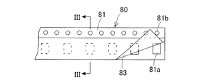
- FIG. 3 is a cross-sectional view of the carrier tape shown in FIG. 2 taken along III-III.
- It is a perspective view of the side side of the feeder of embodiment. It is an enlarged view of the side side rear of the feeder of embodiment. It is an enlarged view of the side rear in the state where the control lever in the feeder of an embodiment was raised. It is an enlarged view of the side rear in the state where lifting of the control lever in the feeder of an embodiment is canceled and carrier tape is conveyed.
- FIG. 10 is a cross-sectional view of the feeder shown in FIG. It is a perspective view of the engagement protrusion of the sprocket with which the feeder of embodiment is provided. It is a figure showing the physical relationship of parts supply position L and the sprocket arranged at the tape shift position in the feeder concerning one modification. It is a figure showing the physical relationship of the cover tape exfoliation position in the feeder concerning one modification, and the sprocket arranged at the tape approach position.
- FIG. 1 Configuration of Component Mounting Machine on which Feeder is Mounted
- the configuration of the component mounting machine 1 on which the feeder of one embodiment is mounted will be described using FIGS. 1 to 3.
- FIG. The feeder of this embodiment is an apparatus applied to the component mounting machine 1 provided on a substrate production line for mounting components on a substrate.
- the component placement machine 1 includes a substrate transfer unit 10, a component supply unit 20, and a component transfer unit 30, as shown in FIG.
- the substrate transfer unit 10 is a device for transferring a substrate 50 such as a circuit board to be produced.
- the substrate transfer unit 10 has a pair of guide rails 11 and 12, a conveyor belt (not shown), and a clamp device (not shown).
- the guide rails 11 and 12 are installed on the base.
- the pair of guide rails 11 and 12 are arranged parallel to each other at an interval.
- the guide rails 11 and 12 guide the substrate 50.
- the conveyor belt is a belt member on which the substrate 50 can be placed, and is provided rotatably.
- the conveyor belt transports the loaded substrate 50 in the transport direction X in which the guide rails 11 and 12 extend.
- the substrate 50 is transported in the transport direction X by the conveyor belt while being guided by the pair of guide rails 11 and 12.
- the clamp device is disposed to position the substrate 50 at a predetermined component mounting position.
- the substrate 50 is positioned by the clamp device when it is transported by the conveyor belt to a predetermined component mounting position.
- the component supply unit 20 is a device for supplying the component 60 to be mounted on the substrate 50 to a predetermined component supply position L.
- the component 60 may include micro components such as, for example, 0201 size (0.2 mm ⁇ 0.1 mm).
- the component supply unit 20 has a slot 21, a feeder 22, and a reel holding unit 23.
- the slot 21 is attached to the base.
- the slots 21 are disposed in a direction (hereinafter, referred to as an orthogonal direction) Y perpendicular to the transport direction X with respect to the substrate transport unit 10.
- the slot 21 is a holding unit to which the feeder 22 is detachably mounted.
- a plurality of slots 21 are provided side by side in the transport direction X.
- the reel holding portion 23 is capable of holding the two reels 70 and 71 exchangeably and rotatably.
- the reel holding portion 23 has a first holding portion 23 a corresponding to the reel 70 and a second holding portion 23 b corresponding to the reel 71.
- the reel holding unit 23 is disposed in the orthogonal direction Y with respect to the feeder 22.
- the first holding portion 23 a and the second holding portion 23 b are arranged in the orthogonal direction Y.
- a plurality of reel holding portions 23 are provided side by side in the transport direction X corresponding to the slots 21, that is, the feeders 22.
- Each of the reels 70 and 71 is a rotating body around which a carrier tape 80 containing a plurality of parts 60 is wound.
- the carrier tape 80 is a tape member in which a plurality of components 60 are accommodated in a line in the longitudinal direction.
- the carrier tape 80 has a base tape 81, a bottom tape 82, and a cover tape 83, as shown in FIGS.
- the base tape 81 is made of a flexible material such as paper or resin.
- An accommodation hole 81 a is provided in the base tape 81 in a penetrating manner.
- the accommodation hole 81 a is a hole for accommodating the component 60.
- the accommodation holes 81 a are provided at predetermined intervals in the longitudinal direction of the base tape 81.
- An engagement hole 81b is also provided through the base tape 81.
- the engagement hole 81b is a hole for engaging an engagement protrusion of a sprocket described later.
- the engagement hole 81b is formed in a substantially circular or elliptical shape.
- the engagement hole 81 b has a size that allows engagement of an engagement projection of a sprocket described later.
- the engagement holes 81 b are provided at predetermined intervals in the longitudinal direction of the base tape 81.
- the accommodation holes 81a are arranged in a line in the longitudinal direction on one side in the width direction of the base tape 81, and the engagement holes 81b are arranged in a line in the longitudinal direction on the other side in the width direction of the base tape 81. Is located in The spacing pitch of the accommodation holes 81a in the longitudinal direction of the base tape 81 and the spacing pitch of the engagement holes 81b correspond in advance, for example, the spacing pitch of the accommodation holes 81a is relative to the spacing pitch of the engagement holes 81b. It is doubled.
- the bottom tape 82 is bonded to the lower surface (specifically, the entire surface) of the base tape 81.
- the bottom tape 82 has a function of holding the component 60 accommodated in the accommodation hole 81 a of the base tape 81 and preventing the component 60 from falling off.
- the bottom tape 82 is made of a transparent or translucent paper material, a polymer film or the like.
- the cover tape 83 is adhered to the upper surface of the base tape 81 (the portion where the engagement hole 81 b is provided may be excluded).
- the cover tape 83 has a function of closing the upper portion of the accommodation hole 81 a of the base tape 81 and preventing the component 60 accommodated in the accommodation hole 81 a from jumping out.
- the cover tape 83 is made of a transparent polymer film or the like.
- the feeder 22 is detachably mounted to the slot 21.
- the feeder 22 stores the carrier tape 80 by feeding the carrier tape 80 wound around the reels 70 and 71 held by the reel holding unit 23 in the orthogonal direction Y orthogonal to the conveyance direction X of the substrate 50. It is an apparatus which supplies the components 60 accommodated in the hole 81a to a predetermined component supply position L. Details of the feeder 22 will be described later.
- the component transfer unit 30 is a device for transferring the component 60 supplied to the predetermined component supply position L toward the substrate 50 positioned at the predetermined component mounting position from the carrier tape 80.
- the component transfer unit 30 has a Y-axis slider 31, an X-axis slider 32, and a mounting head 33.
- the Y-axis slider 31 is supported on the base by guide rails 34 and 35.
- the guide rails 34 and 35 extend in the orthogonal direction Y orthogonal to the conveyance direction X of the substrate 50 by the substrate conveyance unit 10, and are disposed above the substrate conveyance unit 10.
- the Y-axis slider 31 is movable along the guide rails 34 and 35 in the orthogonal direction Y.
- a Y-axis servomotor (not shown) is mechanically connected to the Y-axis slider 31. The Y-axis slider 31 is moved in the orthogonal direction Y by the Y-axis servomotor.
- the X-axis slider 32 is attached to the Y-axis slider 31 so as to be movable in the transport direction X.
- An X-axis servomotor (not shown) fixed to the Y-axis slider 31 is mechanically connected to the X-axis slider 32.
- the X-axis slider 32 is moved in the transport direction X by the X-axis servomotor.
- the mounting head 33 is attached to the X-axis slider 32.
- the mounting head 33 detachably holds a suction nozzle (not shown) capable of suctioning the component 60.
- the mounting head 33 may be capable of holding a plurality of suction nozzles.
- the mounting head 33 is movable in the vertical direction Z orthogonal to both the transport direction X and the orthogonal direction Y.
- the suction nozzle of the mounting head 33 sucks the component 60 supplied to the predetermined component feeding position L by the component feeding unit 20 using a negative pressure or the like, and releases the suctioned component 60 to release the suctioned component 60. It mounts on the substrate 50 positioned at the mounting position.
- a substrate camera 36 is attached to the X-axis slider 32.
- the substrate camera 36 picks up an image of the reference mark of the substrate 50 positioned at a predetermined component mounting position from above to obtain substrate position reference information, or the component 60 supplied to the predetermined component supply position L Images are taken from above to obtain component position information.
- the component position information is used for position control and attitude control of the suction nozzle when the component 60 is suctioned to the suction nozzle of the mounting head 33.
- the substrate position reference information is used for position control and attitude control of the suction nozzle when the component 60 suctioned to the suction nozzle of the mounting head 33 is attached to the substrate 50.
- a component camera 37 is attached to the base of the component transfer unit 30.
- the component camera 37 captures an image of the component 60 sucked by the suction nozzle of the mounting head 33 from below, and acquires posture information and the like of the component 60.
- the posture information is used for position control and posture control of the suction nozzle when the component 60 suctioned to the suction nozzle of the mounting head 33 is attached to the substrate 50.
- FIG. 1 The feeder 22 feeds the carrier tape 80 wound around the reels 70 and 71 held by the reel holding unit 23 in the orthogonal direction Y, and supplies the components 60 accommodated in the carrier tape 80 to predetermined components. Supply to position L.
- the feeder 22 includes a feeder main body 100, a tape guide 110, and a sprocket 120, as shown in FIG.
- the feeder body 100 is formed in a flat box shape.
- the feeder main body 100 includes a tape insertion unit 101 and a tape discharge unit 102.
- the tape insertion unit 101 is an insertion port for inserting the carrier tape 80.
- the tape insertion unit 101 is provided at the rear of the feeder main body 100 (that is, at a position opposite to the substrate transfer unit 10).
- the tape discharge unit 102 is a discharge port for discharging the carrier tape 80 to the outside.
- the tape ejection unit 102 is provided at the front of the feeder main body 100 (that is, at a portion on the substrate conveyance unit 10 side).
- a tape transport path 111 is provided in the feeder main body 100.
- the tape transport path 111 is a rail extending in the transport direction of the carrier tape 80 between the tape insertion unit 101 and the tape discharge unit 102.
- the transport direction of the carrier tape 80 coincides with the orthogonal direction Y orthogonal to the transport direction X of the substrate 50 described above when the feeder 22 is mounted in the slot 21 of the component supply unit 20.
- the tape transport path 111 supports the lower surface of the carrier tape 80 being transported and guides it.
- the tape transport path 111 is formed to have a path width equal to or slightly larger than the dimension in the width direction orthogonal to the longitudinal direction of the carrier tape 80.
- the tape transport path 111 is inclined so as to be gradually higher from the rear to the front.
- the foremost part of the tape transport path 111 is formed horizontally.
- the feeder main body 100 is provided with a tape guide 110.
- the tape guide 110 is a member for guiding the carrier tape 80 conveyed on the tape conveyance path 111 between the tape insertion unit 101 and the tape discharge unit 102.
- the tape guide 110 is disposed above the front sprocket 122 described later.
- the tape guide 110 is formed in an inverted U-shape in which the cross-sectional shape opens downward.
- the tape guide 110 may be separately attached to the feeder main body 100, or may be integrally provided on the feeder main body 100.
- the tape guide 110 has a pair of guide side walls 112 and 113.
- the guide side walls 112 and 113 respectively extend along the orthogonal direction Y which is the conveyance direction of the carrier tape 80 between the tape insertion portion 101 and the tape discharge portion 102.
- the guide side walls 112 and 113 restrict the movement of the carrier tape 80 (specifically, the carrier tape 80 engaged with the front sprocket 122) in the width direction on the tape conveyance path 111, and the carrier being conveyed It is a side wall for guiding the tape 80 in its width direction.
- the guide side wall 112 is a side wall of the both sides in the width direction of the carrier tape 80 on the tape transport path 111 where the side face on the side where the engagement hole 81 b is disposed is opposed.
- the guide side wall 113 is a side wall on which the side surface on the side where the accommodation hole 81 a is disposed among the side surfaces in the width direction of the carrier tape 80 on the tape transport path 111 is opposed.
- the guide side wall 112 and the guide side wall 113 are disposed to face each other in parallel, sandwiching the tape transport path 111 in the width direction, and the direction orthogonal to the orthogonal direction Y by the path width of the tape transport path 111 That is, they are separated in the transport direction X) of the substrate 50.
- the sprocket 120 is a disk-shaped member provided below the tape conveyance path 111 in the feeder body 100.
- the sprocket 120 is a rotating body that rotates in a direction (that is, a forward direction) in which the carrier tape 80 on the tape conveyance path 111 is conveyed from the side of the tape insertion portion 101 toward the side of the tape discharge portion 102.
- the sprocket 120 may be capable of rotating in the direction (that is, the reverse direction) in which the carrier tape 80 is transported from the tape discharge unit 102 side to the tape insertion unit 101 side.
- the sprocket 120 has a rear sprocket 121 and a front sprocket 122.
- the rear sprocket 121 is rotatably attached to the rear side of the tape transport path 111 in the feeder body 100.
- the rear-side sprocket 121 sends the carrier tape 80 inserted into the tape insertion portion 101 toward the tape discharge portion 102 along the tape transport path 111 by forward rotation.
- the front sprocket 122 is rotatably attached to the front side of the tape transport path 111 in the feeder body 100.
- the front-side sprocket 122 directs the carrier tape 80 transported along the tape transport path 111 from the tape insertion section 101 by forward rotation toward the tape ejection section 102 and further from the tape ejection section 102 to the outside. send.
- Two rear sprockets 121 are provided along the tape transport path 111.
- the upstream side (i.e., the rear side) rear sprocket 121 is referred to as a first rear sprocket 121-1
- the downstream side (i.e., the front side) rear sprocket 121 is referred to as a second rear sprocket 121-2. I will refer to each.
- the first rear sprocket 121-1 and the second rear sprocket 121-2 rotate synchronously in the same rotational direction.
- Two front sprockets 122 are provided along the tape transport path 111.
- the upstream (i.e., rear) front sprocket 122 is referred to as a first front sprocket 122-1
- the downstream (i.e., front) front sprocket 122 is referred to as a second front sprocket 122.
- the first front sprocket 122-1 and the second front sprocket 122-2 rotate in synchronization with each other in the same rotation direction.
- Each sprocket 120 (specifically, the sprockets 121-1, 121-2, 122-1, 122-2) has an engagement protrusion 123, respectively.
- the engagement protrusions 123 are external teeth that protrude radially outward on the outer periphery of the sprocket 120.
- the engaging projection 123 of the second rear sprocket 121-2, the engaging projection 123 of the first front sprocket 122-1, and the engaging projection 123 of the second front sprocket 122-2 are all on the outer circumference thereof. It is provided at every predetermined angle over the circumference.
- the engagement protrusion 123 of the first rear sprocket 121-1 is provided on a part of the outer periphery thereof. That is, the first rear sprocket 121-1 has a portion where the engaging projection 123 is not provided on the outer periphery thereof.
- a window hole 114 is provided in a portion of the tape transport path 111 located above each sprocket 120.
- Each sprocket 120 is arranged such that an engagement protrusion 123 near the upper end thereof projects onto the tape transport path 111 through the window hole 114.
- the engagement protrusion 123 is engageable with the engagement hole 81 b of the carrier tape 80 in a state of projecting onto the tape conveyance path 111.
- the engaging projection 123 is formed to have a substantially rectangular cross-sectional shape, and is formed so that the circumferential width gradually decreases from the radial inner side to the radial outer side, that is, the side view has a trapezoidal shape. It is done.
- the engagement protrusion 123 has a size capable of engaging with the engagement hole 81 b of the carrier tape 80. As shown in FIGS. 9 and 10, the engagement projection 123 is formed to engage with the engagement hole 81b of the carrier tape 80 in a state where the projection center C coincides with the hole center O. Specifically, as shown in FIG.
- the engagement projection 123 has the maximum dimension (specifically, the dimension of its diagonal) TAmax of the radially outer end portion the hole diameter H of the engagement hole 81 b of the carrier tape 80. So that the maximum dimension (specifically, the dimension of its diagonal) TBmax of the radially inner root portion is slightly larger than the hole diameter H of the engagement hole 81b of the carrier tape 80. Is formed.
- Each sprocket 120 has a gear 124.
- the gear 124 is formed on the inner diameter side of the outer periphery of the sprocket 120 on which the engagement protrusion 123 is provided.
- the gear 124 is accommodated below the tape conveyance path 111 without protruding from the window hole 114 onto the tape conveyance path 111.
- the feeder 22 includes a rear side motor 130 mounted on the rear side of the feeder body 100.
- the rear motor 130 is a servomotor that rotates the rear sprocket 121, that is, the first rear sprocket 121-1 and the second rear sprocket 121-2.
- the rear side motor 130 can rotate the rear side sprockets 121-1 and 121-2 in the positive direction.
- the rear motor 130 may be capable of rotating the rear sprockets 121-1 and 121-2 in the reverse direction.
- a drive gear 132 is provided on the rotary shaft 131 of the rear side motor 130.
- the drive gear 132 meshes with the gear 124 of the rear sprockets 121-1 and 121-2 via two gears 133 and 134 rotatably attached to the feeder body 100.
- the rotation is transmitted to the first rear side sprocket 121-1 and the second rear side sprocket 121-2 while being decelerated using the gears 133 and 134.
- the rear sprockets 121-1 and 121-2 rotate in synchronization with each other.
- the feeder 22 includes a front side motor 140 attached to the front side of the feeder body 100.
- the front motor 140 is a servomotor that rotates the front sprocket 122, that is, the first front sprocket 122-1 and the second front sprocket 122-2.
- the front motor 140 can rotate the front sprockets 122-1 and 122-2 in the forward direction.
- the front side motor 140 may be capable of rotating the front side sprockets 122-1 and 122-2 in the reverse direction.
- a drive gear 142 is provided on the rotary shaft 141 of the front side motor 140.
- the drive gear 142 meshes with the gear 124 of the front sprockets 122-1 and 122-2 via two gears 143 and 144 rotatably attached to the feeder body 100.
- the front side motor 140 when the front side motor 140 is rotated, the rotation is transmitted to the first front side sprocket 122-1 and the second front side sprocket 122-2 while being decelerated using the gears 143 and 144.
- the front sprockets 122-1 and 122-2 rotate in synchronization with one another.
- the feeder 22 includes an upper surface pressing member 150.
- the upper surface pressing member 150 is disposed above the tape conveyance path 111 and formed parallel to the tape conveyance path 111 between the second rear sprocket 121-2 and the first front sprocket 122-1. It is done.
- a pivot portion 151 is formed at the front end portion of the upper surface pressing member 150.
- the shaft support portion 151 is supported by a shaft portion provided on the feeder main body 100.
- the upper surface pressing member 150 is attached to the feeder main body 100 so as to be swingable by the shaft support 151.
- the upper surface pressing member 150 is biased downward by a biasing member 152 such as a torsion spring.
- the upper surface pressing member 150 has a function of pressing the upper surface of the carrier tape 80 conveyed along the tape conveyance path 111 to prevent the carrier tape 80 from floating when being urged downward by the urging member 152. Have.
- the feeder 22 includes an inlet pressing member 153, a downstream pressing member 154, and an operation lever 155.
- the inlet pressing member 153 is disposed in the vicinity of the tape insertion portion 101 above the tape conveyance path 111 and formed parallel to the rear portion of the tape conveyance path 111.
- the downstream side pressing member 154 is disposed on the front side (downstream side) with respect to the inlet pressing member 153 above the tape conveyance path 111.
- the inlet pressing member 153 and the downstream pressing member 154 are provided so as to be capable of coming into and coming out of contact with the tape transport path 111, respectively.
- the inlet pressing member 153 is disposed below the rear of the downstream pressing member 154 and is attached to the rear of the downstream pressing member 154 via a pair of shafts 156.
- a spring 157 is attached to the pair of shafts 156 to bias the inlet pressing member 153 downward.
- the inlet pressing member 153 has a function of pressing the carrier tape 80 inserted into the tape insertion portion 101 toward the tape transport path 111 when biased downward by the spring 157.
- the downstream side pressing member 154 is attached to the support members 158-1 and 158-2 attached to the feeder main body 100 via a pair of shafts 159-1 and 159-2.
- a spring 160 for biasing the downstream side pressing member 154 downward is attached to the shafts 159-1 and 159-2.
- the downstream pressing member 154 has a function of pressing the carrier tape 80 toward the tape conveyance path 111 on the downstream side of the inlet pressing member 153 when the downstream pressing member 154 is biased downward by the spring 160.
- the control lever 155 is provided to project rearward above the position of the tape insertion portion 101 of the feeder main body 100.
- the control lever 155 is rotatably supported at the rear of the feeder body 100 about a pivot 161.
- the operating lever 155 is rotated about the pivot 161 by the operator.
- An inlet pressing member 153 is operatively connected to the operation lever 155.
- the inlet pressing member 153 has an engaging member 153 a disposed between the pair of shafts 156.
- An actuating engagement portion 155 a is provided at the front-rear central portion of the operation lever 155.
- the actuating engagement portion 155 a is engaged with the lower surface of the engagement member 153 a of the inlet pressing member 153.
- the operating lever 155 is pivoted in a predetermined direction (counterclockwise in FIG. 5) by the biasing force of the spring 162. As shown in FIG.
- control lever 155 is not applied with a force against the biasing force of the spring 162 (that is, a force in the direction opposite to the pivoting direction by the biasing force (clockwise in FIG. 5)).
- the operation engagement portion 155a is held at a predetermined lower end position, and the inlet pressing member 153 is pressed toward the tape conveyance path 111 by the biasing force of the spring 157. Insertion is impossible.
- a baffle plate 163 is pivotally supported at the rear of the inlet pressing member 153.
- the baffle plate 163 has a function of closing the tape insertion portion 101 by its own weight and making it impossible to insert a new carrier tape 80 in a state where the inlet pressing member 153 is pressed toward the tape conveyance path 111. There is.
- the baffle plate 163 is engaged with the rear portion of the downstream side pressing member 154 and pivoted when the inlet pressing member 153 is lifted, and opens the tape insertion portion 101 so that a new carrier tape 80 can be inserted.
- a stopper member 164 is provided adjacent to the downstream side of the inlet pressing member 153.
- the stopper member 164 is rotatably supported by the downstream side pressing member 154 by a shaft support portion 164a provided at the central portion thereof.
- the stopper member 164 is provided with a contact portion 164 b.
- the contact portion 164 b is provided at a lower portion on the front side than the shaft support portion 164 a of the stopper member 164.
- the contact portion 164 b is a portion that protrudes downward and can contact the tape transport path 111.
- the contact portion 164 b is biased in the direction of contact with the tape transport path 111 by a spring (not shown) provided between the downstream side pressing member 154 and the stopper member 164.
- a stop portion 164c is provided at the rear end portion of the stopper member 164.
- the stop portion 164 c is provided so as to be capable of coming into contact with the tape transport path 111.
- the stop portion 164 c has a rear surface to which the leading end of the carrier tape 80 can abut, and has a function of blocking the conveyance of the carrier tape 80 to the downstream side when contacting the tape conveyance path 111.
- the stop portion 164c is a boundary as to whether or not the engagement between the engagement hole 81b of the carrier tape 80 whose front end is in contact with the rear surface of the stop portion 164c and the engagement projection 123 of the first rear sprocket 121-1 occurs. It is placed in position. This engagement is realized when the stop portion 164 c is separated from the tape transport path 111.
- the stopper member 164 is provided with a protrusion 164 d.
- the protruding portion 164 d is provided on the top of the stopper member 164 in front of the shaft support portion 164 a.
- the protrusion 164 d protrudes upward.
- a cam follower 164e is provided at the tip of the protrusion 164d.
- a cam portion 155 b is formed at the front of the operation lever 155. The cam portion 155b is engageably engaged with the cam follower 164e.
- the cam portion of the operation lever 155 is rotated in a state where the operation lever 155 is rotated about the predetermined position by the biasing force of the spring 162 and the inlet pressing member 153 is in contact with the tape transport path 111.
- 155 b separates from the cam follower 164 e of the stopper member 164.
- the stopper member 164 is pivoted in the opposite direction centering on the shaft support portion 164a by the biasing force of a spring (not shown), and causes the contact portion 164b to abut on the tape transport path 111 and the stop portion 164c. Are kept apart from the tape transport path 111.
- the carrier tape 80 When the carrier tape 80 is inserted into the tape insertion portion 101 in this state, the inserted carrier tape 80 enters between the tape upper surface biasing member and the tape lower surface biasing member in the feeder main body 100, The front end abuts on the stop portion 164 c of the stopper member 164 and is stopped.
- this carrier tape 80 (hereinafter, this carrier tape 80 is referred to as the old carrier tape 80) passes between the tape transport path 111 and the contact portion 164b of the stopper member 164, the old carrier tape 80 is used. The contact portion 164 b is lifted, and the stop portion 164 c of the stopper member 164 contacts the tape transport path 111.
- a new carrier tape 80 (hereinafter, this carrier tape 80 is referred to as a new carrier tape 80) is inserted into the tape insertion portion 101 and stacked on the old carrier tape 80, the new carrier tape 80 After entering between the tape upper surface biasing member and the tape lower surface biasing member, the tip thereof abuts on the stop portion 164c of the stopper member 164 and is stopped.
- the old carrier tape 80 is conveyed on the tape conveyance path 111, the conveyance of the new carrier tape 80 to the downstream side is blocked, and the new carrier tape 80 stands by at that position.
- the feeder 22 is provided with a tape peeling device 165.
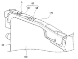
- the tape peeling device 165 is disposed on the front upper side of the feeder body 100 as shown in FIG.
- the tape peeling device 165 is provided on the tape guide 110. That is, the tape guide 110 has a tape peeling device 165.
- the tape peeling device 165 has a peeling member 166 and a folding member 167.
- the peeling member 166 is disposed on the upstream side in the transport direction with respect to the component supply position L. For example, the transport direction on the downstream side of the first front sprocket 122-1 and the transport direction of the second front sprocket 122-2 It is located upstream.
- the peeling member 166 is a blade member that makes it possible to take out (suction or transfer) the component 60 from the accommodation hole 81a at the component supply position L by peeling the cover tape 83 from the base tape 81 of the carrier tape 80. .
- the peeling member 166 is formed substantially horizontally so that the cutting edge of the tip of the peeling member 166 is inserted between the base tape 81 and the cover tape 83 while the carrier tape 80 is transported.
- the peeling member 166 is disposed biased in one of the width directions so as to peel only one of the two sides (two places) in the width direction across the housing hole 81a to which the base tape 81 and the cover tape 83 are bonded. It is formed.
- the end of the peeling member 166 may be formed at a widthwise position corresponding to one of the two adhesive portions of the base tape 81 and the cover tape 83. Therefore, when the cover tape 83 is peeled off from the base tape 81 by the peeling member 166, the cover tape 83 is peeled off from the base tape 81 on one end side in the width direction and is bonded to the base tape 81 on the other end side. .
- the folding member 167 is disposed on the downstream side in the conveying direction with respect to the peeling member 166 (that is, the peeling position at which the cover tape 83 is peeled from the base tape 81 by the peeling member 166).
- the direction is arranged upstream.
- the folding member 167 raises and folds the one end side in the width direction of the peeled cover tape 83 (specifically, the end side of the both ends in the width direction of the carrier tape 80 where the accommodation hole 81a for accommodating the component 60 is disposed). It is a member.
- the folding member 167 is formed in a plate shape that extends substantially horizontally.
- a component pickup portion is provided on the upper guide wall of the tape guide 110.
- the component takeout portion is a hole which can be taken out of the component 60 accommodated in the accommodation hole 81a of the base tape 81 and opened in the guide upper wall.
- the position at which the component extraction portion is provided is on the downstream side of the peeling position with respect to the conveying direction, and the conveying direction downstream of the first front sprocket 122-1 and the conveyance of the second front sprocket 122-2 The direction is upstream.
- the position where the component pick-up portion is provided is the above-described predetermined component supply position L of the feeder 22.
- the component pick-up portion is formed in such a size that a suction nozzle for sucking and holding the component 60 in the component transfer portion 30 does not contact the guide upper wall when the component 60 is transferred.
- the portion of the carrier tape 80 which has passed through the component pickup portion hangs down from the front of the feeder 22 and is discharged to the outside of the feeder 22.
- the old carrier tape 80 is wound around the reel 70 held by the first holding portion 23a, and the new carrier tape 80 is held by the second holding portion 23b. It is wound around 71.
- the operation lever 155 is held by the biasing force of the spring 162, as shown in FIG. 5, the inlet pressing member 153 is held at a position abutted against the tape conveyance path 111, and the baffle plate 163 is by its own weight.
- the tape transport path 111 is closed by being rotated.
- the inlet pressing member 153 resists the biasing force of the spring 157 by the elevation of the actuating engagement portion 155a. To be raised. In this case, the inlet pressing member 153 is separated from the tape conveyance path 111, and the baffle plate 163 is rotated by the downstream pressing member 154 to open the tape insertion portion 101 in a state where the carrier tape 80 can be inserted. . At the same time, the stopper member 164 is rotated by the cam portion 155 b of the operation lever 155, and the stop portion 164 c abuts on the tape conveyance path 111.
- the baffle plate 163 closes the tape insertion portion 101 by its own weight.
- the stopper member 164 causes the contact portion 164b to abut the tape transport path 111 and separates the stop portion 164c from the tape transport path 111 by the biasing force of the spring.
- Insertion of the old carrier tape 80 into the tape insertion unit 101 is detected using various sensors, the presence of the old carrier tape 80 on the tape conveyance path 111 is detected, and the operation lever 155 returns to the original position. If it is detected, the rear motor 130 is driven such that the first and second rear sprockets 121-1 and 121-2 rotate in the positive direction. When the rear side motor 130 is driven, the first and second rear side sprockets 121-1 and 121-2 are rotated in the forward direction.
- the leading end side of the old carrier tape 80 is permitted to be transported from the stop portion 164c to the downstream side in the transport direction by separation of the stop portion 164c from the tape transport path 111, and the first rear side sprocket 121-1 Is rotated forward in a state in which the engaging protrusion 123 and the engaging hole 81b of the old carrier tape 80 are engaged, the old carrier tape 80 is rotated by the forward rotation of the first rear sprocket 121-1, and the tape discharging portion 102 is rotated. It is transported to the side. When this conveyance is performed, the downstream side pressing member 154 is lifted by the old carrier tape 80 against the biasing force of the spring 160, and the old carrier tape 80 is between the downstream side pressing member 154 and the tape conveyance path 111. It is transported.
- the engagement protrusion 123 of the first rear sprocket 121-1 is provided only on a part of the outer periphery of the first rear sprocket 121-1. Therefore, after the engagement protrusion 123 is engaged with the engagement hole 81b of the old carrier tape 80, the old carrier tape 80 is intermittently sent toward the tape discharge portion 102 side. Therefore, rapid pull-in of the carrier tape 80 by the first rear sprocket 121-1 is avoided.
- the downstream side pressing member 154 is lifted, the pivoting portion 164a of the stopper member 164 is integrally lifted.
- the engagement protrusion 123 of the second rear sprocket 121-2 is in the engagement hole 81b at the tip end of the old carrier tape 80. Engage. After this engagement, the old carrier tape 80 is conveyed toward the tape discharge portion 102 by forward rotation of the second rear sprocket 121-2. As described above, the engagement protrusion 123 of the second rear sprocket 121-2 is provided over the entire outer circumference of the second rear sprocket 121-2. For this reason, after the engagement projection 123 of the second rear sprocket 121-2 is engaged with the engagement hole 81b of the old carrier tape 80, the movement of the old carrier tape 80 to the tape discharging portion 102 is short. To be done.
- the old carrier tape 80 rotates forward of the first front sprocket 122-1.
- the tape is transported to the side of the tape discharge unit 102, and the cover tape 83 is peeled off from the old carrier tape 80 by the tape peeling device 165 during the conveyance.
- the engaging projection 123 of the second front sprocket 122-2 engages with the engaging hole 81b of the old carrier tape 80, the old carrier tape 80 rotates forward of the second front sprocket 122-2.
- the component 60 accommodated in the old carrier tape 80 is positioned at the component supply position L by the component transfer unit 30 at each rotation stop during the intermittent rotation of the rear sprocket 121 and the front sprocket 122. It will be transferred.
- the old carrier tape 80 pushes and lifts the contact portion 164b of the stopper member 164, so that the stopper member 164 resists the biasing force of the spring. It is pivoted about the pivot portion 164a. Thereby, the stop portion 164 c of the stopper member 164 comes in contact with the upper surface of the old carrier tape 80 and abuts on it.
- the new carrier tape 80 is maintained at a stop and the end which is the rear end of the old carrier tape 80 is transported to the downstream side in the transport direction than the front end which is the front end of the new carrier tape 80,
- the new carrier tape 80 is in contact with the upper surface of the tape transport path 111 on the upstream side of the old carrier tape 80 in the transport direction, and the engaging protrusion of the first rear sprocket 121-1 is engaged with the engaging hole 81b of the new carrier tape 80 123 is engaged.
- the new carrier tape 80 enters the gap formed between the tape transport path 111 and the stopper member 164 due to the presence of the old carrier tape 80, The sheet is conveyed toward the tape ejection unit 102 side.
- the tip of the new carrier tape 80 lifts the contact portion 164b, as described above, the stopper member 164 is pivoted against the biasing force of the spring, and the stop portion 164c prevents the new carrier tape 80 from entering. Be done.
- the conveyance of the second carrier tape 80 can be started when the conveyance of the first carrier tape 80 is completed. .
- the two carrier tapes 80 are not transported from the stop portion 164c downstream in the transport direction in the overlapping state, and the two carrier tapes 80 can be transported continuously in time.
- the supply of the parts 60 stored in the part 80 to the parts supply position L can be performed continuously without interruption. Further, by driving both the rear side motor 130 and the front side motor 140 so that each sprocket 120 rotates forward, the component 60 accommodated in the carrier tape 80 is supplied to the predetermined component supply position L. be able to.
- the base tape 81 of the carrier tape 80 is provided with the engagement hole 81b with which the engagement projection 123 of the sprocket 120 is engaged.
- the engagement holes 81 b are arranged in a line in the longitudinal direction of the base tape 81.
- the feeder main body 100 of the feeder 22 has a tape transport path 111 for supporting the lower surface of the carrier tape 80 and a pair of guide side walls 112 and 113 for guiding the carrier tape 80 in a state in which it can contact the side surface in the width direction.
- a tape guide 110 is provided.
- the tape transport path 111 has a path width equal to or slightly larger than the dimension of the carrier tape 80 in the width direction.
- the guide side wall 112 and the guide side wall 113 are separated in the transport direction X (that is, in the width direction of the carrier tape 80 to be guided) by the path width of the tape transport path 111.
- the sprocket 120 is disposed in the feeder main body 100 such that the engagement protrusion 123 near the upper end protrudes upward through the window hole 114 of the tape conveyance path 111. Specifically, the engagement protrusion 123 is engaged with the engagement hole 81b of the carrier tape 80 so that the projection center C of the engagement protrusion 123 engages with the engagement hole 81b of the carrier tape 80 in a state of coinciding with the hole center O.
- the maximum dimension TAmax of the tip portion on the radially outer side is smaller than the hole diameter H of the diameter direction H, and the maximum dimension TBmax of the root portion on the radially inner side is larger.
- the engaging projections 123 of the sprocket 120 (in particular, the front sprocket 122) projecting upward through the window hole 114 of the tape conveyance path 111 are supported by the tape conveyance path 111 on the lower surface and the tape guides on the side.
- the engagement holes 81 b of the carrier tape 80 guided by the guide side walls 112 and 113 of 110 are engaged.
- a tip portion whose maximum dimension TAmax of the engagement protrusion 123 is smaller than the hole diameter H of the engagement hole 81b of the carrier tape 80 is inserted into the engagement hole 81b.
- a root portion having a maximum dimension TBmax of the engagement protrusion 123 larger than the hole diameter H of the engagement hole 81b is inserted into the engagement hole 81b,
- the side surface of the root portion is realized by contacting the edge of the engagement hole 81b.
- the carrier tape 80 inserted into the tape insertion portion 101 of the feeder main body 100 is guided by the guide side walls 112 and 113 of the tape guide 110 by the side while being supported by the tape conveyance path 111 on the lower surface and sprockets in the engagement holes 81b.
- the sprocket 120 is rotated in a state in which the engagement projection 123 of 120 is engaged, and is sent toward the tape discharge unit 102 side.
- the sprocket 120 has a distance D from the engagement protrusion 123 to one of the guide side walls 112 and 113 of the pair of guide side walls 112 and 113 of the tape guide 110.
- Tape that becomes smaller than the dimension W in the width direction from the alignment hole 81 b to the side edge in the width direction (specifically, the side edge of the carrier tape 80 placed on the tape transport path 111 on the guide side wall 112 side) It is arranged at the shift position (D ⁇ W).
- is set to the maximum value that can be taken as the tolerance of the width of the carrier tape 80 or the distance between the pair of guide side walls 112 and 113 or as a cumulative tolerance of those tolerances. Just do it.
- the sprocket 120 disposed at the tape shift position where the relationship of D ⁇ W described above holds is specifically the front sprocket 122 provided in the feeder 22 (ie, the first and second front sprockets 122). -1, 122-2).
- the separation distance D is, for example, the distance from the center C of the engagement protrusion 123 in the axial direction (that is, the thickness direction of the sprocket 120) in which the rotation axis of the sprocket 120 extends, to the wall surface of the guide side wall 112 Good.
- the dimension W may be, for example, the distance from the hole center O of the engagement hole 81b of the carrier tape 80 to the side end in the width direction.
- the guide side wall targeted for the separation distance D and the side end of the carrier tape 80 targeted for the dimension W are guided on the tape transport path 111 as shown in FIGS. 9 and 10, respectively.
- the guide side wall 112 or the side end of the carrier tape 80 on which the engaging hole 81b is disposed are either one of the pair of guide side walls 112 and 113 of the tape guide 110 or both side ends of the carrier tape 80 in the width direction.
- the engagement protrusion 123 of the sprocket 120 is engaged with the engagement hole 81 b of the carrier tape 80 from its tip.
- a force is generated that causes the engaging protrusion 123 to move the region around the engaging hole 81 b of the carrier tape 80 in the width direction on the guide side wall 112 side.
- the amount by which the carrier tape 80 can be moved in the width direction by this force is larger than the amount by which the above-described separation distance D is equal to the above-described dimension W.
- the carrier tape 80 When the carrier tape 80 is fed along the tape transport path 111 while being pressed against one of the pair of guide side walls 112 and 113, the carrier tape 80 is in contact with the guide side wall 112 by the rotation of the sprocket 120. Since the tape is conveyed linearly on the tape conveyance path 111, meandering of the carrier tape 80 on the tape conveyance path 111 can be suppressed. Therefore, the accuracy of the position in the width direction of the component 60 accommodated in the accommodation hole 81a of the carrier tape 80 with respect to the feeder main body 100 can be stabilized.
- the carrier tape 80 accommodating particularly the small component 60 is fed, it is possible to suppress excessive positional deviation in the width direction with respect to the width length of the component 60, whereby the carrier tape 80 is used. Even if the component 60 to be accommodated is minute, the suction accuracy when the suction nozzle of the mounting head 33 sucks the component 60 at the component supply position L can be improved, and the component 60 is mounted on the substrate 50 Can improve the productivity of
- the front-side sprocket 122 included in the feeder 22 is disposed at the tape shift position where the relationship of D ⁇ W described above is established. For this reason, in the region of the tape transport path 111 extending from the first front sprocket 122-1 to the second front sprocket 122-2 of the feeder 22, the component 60 housed in the carrier tape 80 relative to the feeder main body 100 The accuracy of the position in the width direction can be stabilized, whereby the improvement of the suction accuracy and the improvement of the productivity can be maximized.
- the first front sprocket 122-1 comprises the second front sprocket 122-2 in the "upstream sprocket” described in claim 2 of the claims. It corresponds to the "downstream side sprocket” described in claim 2 of the scope.
- two rear sprockets 121 are provided: a first rear sprocket 121-1 and a second rear sprocket 121-2.
- the feeder 22 is not limited to this, and may be applied to one in which one or three or more rear sprockets 121 are provided.
- two front sprockets 122 are provided: a first front sprocket 122-1 and a second front sprocket 122-2.
- the feeder 22 is not limited to this, and may be applied to one in which one or three or more front side sprockets 122 are provided.
- the two first rear sprockets 121-1 and the second rear sprocket 121-2 are connected to one rear motor 130 and rotated in synchronization by the rear motor 130. It is supposed to However, the feeder 22 is not limited to this, and is applied to those in which the rear side sprockets 121-1 and 121-2 are connected to different rear side motors and synchronously rotated by the rear side motors. You may do it.
- the two first front sprockets 122-1 and the second front sprocket 122-2 are connected to one front motor 140 and rotated synchronously by the front motor 140.
- the feeder 22 is not limited to this, and the front sprockets 122-1 and 122-2 are connected to separate front motors and rotated synchronously by the front motors. It may be applied to
- the first and second front sprockets 122-1 and 122-2 included in the feeder 22 are disposed at the tape shift position where the relationship of D ⁇ W described above is established.
- the feeder 22 is not limited to this.
- all the sprockets 120 i.e., the first and second rear side sprockets 121-1 and 121-2 and the first and second front side sprockets 122-1 and 122-2
- the sprockets 120 are as described above. It may be arranged at the tape shift position where the relationship of D ⁇ W is established. That is, the relationship of D ⁇ W described above also holds between the first and second rear sprockets 121-1 and 121-2 and the guide side wall of the tape guide provided on the rear side of the feeder main body 100 of the feeder 22. It may be disposed at the tape shift position.
- the accuracy of the position in the width direction of the component 60 accommodated in the carrier tape 80 with respect to the feeder main body 100 is stabilized in the entire area of the tape conveyance path 111 from the tape insertion unit 101 to the tape discharge unit 102 of the feeder 22.
- the carrier tape 80 is attached to the guide sidewall 112 at the upstream side in the transport direction with respect to the component supply position L It is effective to abut and press. Therefore, as shown in FIG. 12, the sprockets 120 (specifically, only the first front sprocket 122-1) disposed on the upstream side in the transport direction with respect to the component supply position L have the above-mentioned D ⁇ W. It may be disposed at the tape shift position where the relationship is established.
- the carrier tape 80 can be pressed against the one guide side wall 112 on the upstream side in the transport direction with respect to the component supply position L. Therefore, the accuracy of the position of the component 60 in the width direction at the component supply position L Can be stabilized.
- first front sprocket 122-1 disposed on the upstream side in the conveying direction closest to the component supply position L has the tape shift position where the above-mentioned relationship of D ⁇ W is satisfied. It shall be placed in However, all of the first rear sprocket 121-1, the second rear sprocket 121-2 and the first front sprocket 122-1 arranged upstream of the component supply position L in the transport direction are respectively: It may be disposed at the tape shift position where the above-mentioned relationship of D ⁇ W is established.
- the carrier tape 80 can be pressed against the one guide side wall 112 at the engagement position with the sprocket 120 closest to the component supply position L, so that the component 60 at the component supply position L can be The accuracy error of the widthwise position can be minimized, and the position accuracy can be stabilized.
- the positional deviation in the width direction when the carrier tape 80 is fed is likely to occur when the cover tape 83 is peeled off from the carrier tape 80 by the peeling member 166 of the tape peeling device 165.
- the carrier tape 80 in order to stabilize the accuracy of the position in the width direction of the component 60 at the component supply position L, the carrier tape 80 is guided on the downstream side in the transport direction with respect to the peeling position where the cover tape 83 is peeled from the carrier tape 80 It is effective to abut on and press against 112. Therefore, as shown in FIG. 13, the second front sprocket 122-2 disposed on the downstream side in the transport direction with respect to the peeling position described above is disposed at the tape shifting position where the relationship of D ⁇ W described above holds.
- the carrier tape 80 can be brought into contact with one guide side wall 112 and pressed on the downstream side in the transport direction with respect to the peeling position. For this reason, even if there is a gap in the width direction of the carrier tape 80 at the peeling position, the carrier tape 80 is moved from the peeling position to the engaging position with the engagement projection 123 of the second front sprocket 122-2.
- the side wall of the carrier tape 80 can be brought into contact with the guide side wall 112 at the engaged position by correcting the width direction position, the part 60 at the part supply position L downstream of the peeling position in the transport direction The accuracy of the widthwise position can be stabilized.
- the guide side wall 112 of the pair of guide side walls 112 and 113 of the tape guide 110 on the same side as the side where the engagement hole 81 b in the carrier tape 80 is disposed The guide side wall is made to abut and press.
- the feeder 22 is not limited to this, and the guide side wall 113 of the carrier tape 80 on the opposite side to the side on which the engagement hole 81 b is disposed (that is, the same side as the side on which the accommodation hole 81 a is disposed). May be used as guide side walls for bringing the carrier tape 80 into contact and pressing with the sprocket 120.
- the feeder 22 is an automatic loading feeder having the rear side sprocket 121 on the rear side of the feeder body 100 and the front side sprocket 122 on the front side of the feeder body 100.
- the feeder 22 is not limited to this, and may be applied to a feeder that is not an auto loading feeder.
- the carrier tape 80 has a structure in which the bottom tape 82 is adhered to the lower surface of the base tape 81 provided with the through accommodation hole 81 a.
- the carrier tape 80 is not limited to this, and even if it is an embossed carrier tape having a base tape provided with a groove for housing the component 60 without the bottom tape 82 being adhered to the lower surface. Good.
- the feeder 22 is not limited to the embodiment and modification which were mentioned above, It is possible to give a various change in the range which does not deviate from the meaning of invention.
Landscapes
- Engineering & Computer Science (AREA)
- Manufacturing & Machinery (AREA)
- Microelectronics & Electronic Packaging (AREA)
- Supply And Installment Of Electrical Components (AREA)
Abstract
フィーダは、部品を収容する収容部と搬送用の係合孔とが設けられたキャリアテープを搬送方向に送ることにより、収容部に収容された部品を部品供給位置に順次供給する際に、キャリアテープに収容される部品の幅方向位置の精度を安定させるうえで、搬送方向に沿って延びる搬送路が設けられたフィーダ本体と、フィーダ本体に取り付けられ、搬送路上のキャリアテープを搬送方向に直交する幅方向において案内するガイド側壁を有するテープガイドと、フィーダ本体に回転可能に軸支され、搬送路上のキャリアテープの係合孔に係合する係合突起が設けられた、キャリアテープを搬送方向に送り移動させるスプロケットと、を備える。スプロケットは、係合突起からテープガイドのガイド側壁までの離間距離がキャリアテープの係合孔から側端までの幅方向の寸法に比して小さくなるテープ寄せ位置に配置されている。
Description
本明細書は、フィーダに関する。
従来、電子部品などの部品を基板に移載するために部品を部品供給位置に順次供給するフィーダが知られている(例えば、特許文献1参照)。上記特許文献1に記載されたフィーダにおいて、部品は、キャリアテープに所定間隔で設けられた複数の収容部それぞれに収容されている。フィーダは、フィーダ本体と、テープガイドと、スプロケットと、を備えている。フィーダ本体には、テープ挿入部からテープ排出部に向けてキャリアテープの搬送方向に沿って延びる搬送路が設けられている。フィーダ本体には、搬送路上のキャリアテープを案内するテープガイドが取り付けられている。テープガイドは、搬送路上のキャリアテープを搬送方向に直交する幅方向において案内するガイド側壁を有している。
スプロケットは、フィーダ本体に回転可能に軸支されている。スプロケットには、搬送路上のキャリアテープに収容部とは別に設けられた係合孔に係合可能な係合突起が設けられている。スプロケットは、係合突起をキャリアテープの係合孔に係合させながら自転することにより、キャリアテープを搬送方向に送り移動させて部品を部品供給位置に供給する。
上記特許文献1に記載されたフィーダは、また、絞り部を備えている。絞り部は、搬送路上のキャリアテープの両側を案内する一対のガイド側壁間の距離を上流から下流にかけて徐々に狭くするものである。絞り部よりも上流側の搬送路の幅すなわちその搬送路上でのキャリアテープの両側を案内する一対のガイド側壁間の距離は、キャリアテープの幅の最大値よりも若干大きくなるように設定されている。また、絞り部における搬送路の幅すなわち一対のガイド側壁間の距離は、キャリアテープの幅の最大値程度に狭められている。この絞り部によれば、搬送路上で送られるキャリアテープの幅方向のズレ量を小さく抑えることができるので、部品検出位置の誤検出などを低減することができる。
しかしながら、キャリアテープ自体の幅或いは一対のガイド側壁の離間距離には、公差が存在する。このため、上記の如く搬送路に絞り部が設けられていても、公差に起因して一対のガイド側壁間の距離がキャリアテープの幅に比して僅かに大きくなることでキャリアテープとガイド側壁との間に隙間が生じることがある。このため、搬送路に絞り部が設けられていても、キャリアテープが搬送方向に送られるときにフィーダに対する部品の幅方向位置が上記の隙間分だけずれることがあり、その幅方向位置の精度が不安定となるおそれがある。部品の幅方向位置の精度が不安定であると、特に小さい部品を収容するキャリアテープが送られるときに、その微小部品を吸着ノズルが吸着する際の吸着精度が低下してしまう。
本明細書は、キャリアテープに収容される部品の幅方向位置の精度を安定させることが可能なフィーダを開示する。
本明細書は、部品を収容する収容部と搬送用の係合孔とが設けられたキャリアテープを搬送方向に送ることにより、前記収容部に収容された前記部品を部品供給位置に順次供給するフィーダであって、前記搬送方向に沿って延びる搬送路が設けられたフィーダ本体と、前記フィーダ本体に取り付けられ、前記搬送路上の前記キャリアテープを前記搬送方向に直交する幅方向において案内するガイド側壁を有するテープガイドと、前記フィーダ本体に回転可能に軸支され、前記搬送路上の前記キャリアテープの前記係合孔に係合する係合突起が設けられた、前記キャリアテープを前記搬送方向に送り移動させるスプロケットと、を備え、前記スプロケットは、前記係合突起から前記テープガイドの前記ガイド側壁までの離間距離が前記キャリアテープの前記係合孔から側端までの前記幅方向の寸法に比して小さくなるテープ寄せ位置に配置されている、フィーダを開示する。
本開示によれば、スプロケットの回転によってキャリアテープがテープ搬送路に沿って送られる際、キャリアテープの係合孔にスプロケットの係合突起が挿入される過程で、その係合突起がキャリアテープの係合孔周辺の部位をガイド側壁側の幅方向へ移動させる力が発生する。この力によってキャリアテープが幅方向へ移動可能な量は、上記の離間距離が上記の寸法に等しい場合に移動可能な量に比して大きい。このため、キャリアテープの幅やテープガイドの一対のガイド側壁の離間距離に公差があっても、キャリアテープの一方の側端面がガイド側壁に確実に当接して押し付けられるので、キャリアテープがスプロケットの回転によってガイド側壁に当接した状態でテープ搬送路上において直線的に搬送される。従って、キャリアテープの収容孔に収容された部品の、フィーダ本体に対する幅方向位置の精度を安定させることができる。
1.フィーダが搭載される部品装着機の構成
一実施形態のフィーダが搭載される部品装着機1の構成について、図1~図3を用いて説明する。本実施形態のフィーダは、基板に部品を装着する基板生産ライン上に設けられる部品装着機1に適用される装置である。部品装着機1は、図1に示す如く、基板搬送部10と、部品供給部20と、部品移載部30と、を備えている。
一実施形態のフィーダが搭載される部品装着機1の構成について、図1~図3を用いて説明する。本実施形態のフィーダは、基板に部品を装着する基板生産ライン上に設けられる部品装着機1に適用される装置である。部品装着機1は、図1に示す如く、基板搬送部10と、部品供給部20と、部品移載部30と、を備えている。
基板搬送部10は、生産対象の回路基板などの基板50を搬送する装置である。基板搬送部10は、一対のガイドレール11,12と、コンベアベルト(図示せず)と、クランプ装置(図示せず)と、を有している。ガイドレール11,12は、基台上に設置されている。一対のガイドレール11,12は、間隔を空けて互いに平行に配置されている。ガイドレール11,12は、基板50を案内する。コンベアベルトは、基板50を載置可能なベルト部材であって、輪転可能に設けられている。コンベアベルトは、載置した基板50を、ガイドレール11,12が延びる搬送方向Xに向けて搬送する。基板50は、一対のガイドレール11,12により案内されつつコンベアベルトにより搬送方向Xに向けて搬送される。クランプ装置は、基板50を所定の部品装着位置に位置決めするように配設されている。基板50は、コンベアベルトにより所定の部品装着位置まで搬送されると、クランプ装置によって位置決めされる。
部品供給部20は、基板50に装着する部品60を所定の部品供給位置Lまで供給する装置である。部品60は、例えば0201サイズ(0.2mm×0.1mm)などの微小部品を含んでもよい。部品供給部20は、スロット21と、フィーダ22と、リール保持部23と、を有している。スロット21は、基台に取り付けられている。スロット21は、基板搬送部10に対して搬送方向Xに直交する方向(以下、直交方向と称す。)Yに配置されている。スロット21は、フィーダ22が着脱可能に装着される保持部である。スロット21は、搬送方向Xに並んで複数設けられている。
リール保持部23は、2つのリール70,71をそれぞれ交換可能かつ回転可能に保持することが可能である。リール保持部23は、リール70に対応した第1保持部23aと、リール71に対応した第2保持部23bと、を有している。リール保持部23は、フィーダ22に対して直交方向Yに配置されている。第1保持部23aと第2保持部23bとは、直交方向Yに並ぶように配置されている。リール保持部23は、スロット21すなわちフィーダ22に対応して、搬送方向Xに並んで複数設けられている。リール70,71はそれぞれ、部品60を複数個収容したキャリアテープ80が巻回される回転体である。
キャリアテープ80は、複数の部品60を長手方向に一列に収容したテープ部材である。キャリアテープ80は、図2及び図3に示す如く、ベーステープ81と、ボトムテープ82と、カバーテープ83と、を有している。ベーステープ81は、紙材や樹脂等の柔軟な材料により構成されている。ベーステープ81には、収容孔81aが貫通して設けられている。収容孔81aは、部品60を収容するための孔である。収容孔81aは、ベーステープ81の長手方向において所定間隔ごとに設けられている。
ベーステープ81には、また、係合孔81bが貫通して設けられている。係合孔81bは、後述のスプロケットの係合突起を係合させるための孔である。係合孔81bは、略円形或いは楕円形に形成されている。係合孔81bは、後述のスプロケットの係合突起が係合することが可能な大きさを有している。係合孔81bは、ベーステープ81の長手方向において所定間隔ごとに設けられている。
上記の収容孔81aは、ベーステープ81の幅方向の一方側において長手方向に一列に配置されていると共に、上記の係合孔81bは、ベーステープ81の幅方向の他方側において長手方向に一列に配置されている。ベーステープ81の長手方向における収容孔81aの間隔ピッチと係合孔81bの間隔ピッチとは、予め対応しており、例えば、収容孔81aの間隔ピッチは、係合孔81bの間隔ピッチに対して2倍である。
ボトムテープ82は、ベーステープ81の下面(具体的には、その全面)に接着されている。ボトムテープ82は、ベーステープ81の収容孔81aに収容された部品60を保持してその部品60の脱落を防止する機能を有している。ボトムテープ82は、透明又は半透明の紙材や高分子フィルムなどにより構成されている。カバーテープ83は、ベーステープ81の上面(尚、係合孔81bが設けられている部分を除いてもよい。)に接着されている。カバーテープ83は、ベーステープ81の収容孔81aの上部を閉塞して、その収容孔81aに収容された部品60の飛び出しを防止する機能を有している。カバーテープ83は、透明な高分子フィルムなどにより構成されている。
フィーダ22は、スロット21に着脱可能に装着される。フィーダ22は、リール保持部23に保持されているリール70,71に巻回されているキャリアテープ80を、基板50の搬送方向Xに直交する直交方向Yに送ることにより、キャリアテープ80の収容孔81aに収容されている部品60を所定の部品供給位置Lまで供給する装置である。フィーダ22の詳細については後述する。
部品移載部30は、所定の部品供給位置Lまで供給された部品60を、キャリアテープ80から所定の部品装着位置に位置決めされている基板50に向けて移載する装置である。部品移載部30は、Y軸スライダ31と、X軸スライダ32と、装着ヘッド33と、を有している。
Y軸スライダ31は、ガイドレール34,35により基台に支持されている。ガイドレール34,35は、基板搬送部10による基板50の搬送方向Xに直交する直交方向Yに延びており、基板搬送部10の上方に配設されている。Y軸スライダ31は、ガイドレール34,35に沿って直交方向Yに向けて移動可能である。Y軸スライダ31には、Y軸サーボモータ(図示せず)が機械的に連結されている。Y軸スライダ31は、Y軸サーボモータにより直交方向Yへ位置移動される。
X軸スライダ32は、Y軸スライダ31に搬送方向Xに向けて移動可能に取り付けられている。X軸スライダ32には、Y軸スライダ31に固定されたX軸サーボモータ(図示せず)が機械的に連結されている。X軸スライダ32は、X軸サーボモータにより搬送方向Xへ位置移動される。
X軸スライダ32には、装着ヘッド33が取り付けられている。装着ヘッド33は、部品60を吸着可能な吸着ノズル(図示せず)を着脱可能に保持している。尚、装着ヘッド33は、複数の吸着ノズルを保持可能であってよい。装着ヘッド33は、搬送方向X及び直交方向Yの双方に直交する上下方向Zに位置移動可能である。装着ヘッド33の吸着ノズルは、部品供給部20によって所定の部品供給位置Lに供給された部品60を負圧などを用いて吸着すると共に、その吸着した部品60をその吸着解除により、所定の部品装着位置に位置決めされている基板50に装着する。
X軸スライダ32には、基板カメラ36が取り付けられている。基板カメラ36は、所定の部品装着位置に位置決めされている基板50の基準マークを上方から撮像して、基板位置基準情報を取得し、又は、所定の部品供給位置Lに供給された部品60を上方から撮像して、部品位置情報を取得する。部品位置情報は、装着ヘッド33の吸着ノズルへの部品60の吸着時にその吸着ノズルの位置制御や姿勢制御に用いられる。また、基板位置基準情報は、装着ヘッド33の吸着ノズルに吸着した部品60の基板50への装着時にその吸着ノズルの位置制御や姿勢制御に用いられる。
また、部品移載部30の基台には、部品カメラ37が取り付けられている。部品カメラ37は、装着ヘッド33の吸着ノズルにより吸着されている部品60を下方から撮像して、その部品60の姿勢情報などを取得する。この姿勢情報は、装着ヘッド33の吸着ノズルに吸着した部品60の基板50への装着時にその吸着ノズルの位置制御や姿勢制御に用いられる。
2.フィーダの構成
次に、フィーダ22の構成について、図4~図11を用いて説明する。フィーダ22は、リール保持部23に保持されているリール70,71に巻回されているキャリアテープ80を直交方向Yに送って、そのキャリアテープ80に収容されている部品60を所定の部品供給位置Lまで供給する。フィーダ22は、図4に示す如く、フィーダ本体100と、テープガイド110と、スプロケット120と、を備えている。
次に、フィーダ22の構成について、図4~図11を用いて説明する。フィーダ22は、リール保持部23に保持されているリール70,71に巻回されているキャリアテープ80を直交方向Yに送って、そのキャリアテープ80に収容されている部品60を所定の部品供給位置Lまで供給する。フィーダ22は、図4に示す如く、フィーダ本体100と、テープガイド110と、スプロケット120と、を備えている。
フィーダ本体100は、扁平な箱形に形成されている。フィーダ本体100は、テープ挿入部101と、テープ排出部102と、を有している。テープ挿入部101は、キャリアテープ80を挿入するための挿入口である。テープ挿入部101は、フィーダ本体100の後部(すなわち、基板搬送部10側とは反対側の部位)に設けられている。テープ排出部102は、キャリアテープ80を外部に排出するための排出口である。テープ排出部102は、フィーダ本体100の前部(すなわち、基板搬送部10側の部位)に設けられている。
フィーダ本体100には、テープ搬送路111が設けられている。テープ搬送路111は、テープ挿入部101とテープ排出部102との間でキャリアテープ80の搬送方向に沿って延びるレールである。尚、キャリアテープ80の搬送方向は、フィーダ22が部品供給部20のスロット21に装着されている場合に上記した基板50の搬送方向Xに直交する直交方向Yに一致する。
テープ搬送路111は、搬送中のキャリアテープ80をその下面を支持して案内する。テープ搬送路111は、キャリアテープ80の長手方向に直交する幅方向の寸法と同じ或いはその寸法に比して僅かに大きな路幅を有するように形成されている。テープ搬送路111は、後部から前部にかけて徐々に高くなるように傾斜している。テープ搬送路111の最前部は、水平に形成されている。
フィーダ本体100には、テープガイド110が設けられている。テープガイド110は、テープ挿入部101とテープ排出部102との間のテープ搬送路111上で搬送されるキャリアテープ80を案内する部材である。テープガイド110は、後述の前部側スプロケット122の上方に配置されている。テープガイド110は、断面形状が下方に開放する逆U字状になるように形成されている。尚、テープガイド110は、フィーダ本体100に別体で取り付けられたものであってもよいし、また、フィーダ本体100に一体で設けられたものであってもよい。
テープガイド110は、一対のガイド側壁112,113を有している。ガイド側壁112,113はそれぞれ、テープ挿入部101とテープ排出部102との間でキャリアテープ80の搬送方向である直交方向Yに沿って延びている。ガイド側壁112,113は、テープ搬送路111上のキャリアテープ80(具体的には、前部側スプロケット122に係合するキャリアテープ80)の幅方向への移動を規制して、搬送中のキャリアテープ80をその幅方向において案内する側壁である。
ガイド側壁112は、テープ搬送路111上のキャリアテープ80の幅方向の両側面のうち係合孔81bが配置される側の側面が対向する側壁である。また、ガイド側壁113は、テープ搬送路111上のキャリアテープ80の幅方向の両側面のうち収容孔81aが配置される側の側面が対向する側壁である。ガイド側壁112とガイド側壁113とは、テープ搬送路111を幅方向で挟んで互いに平行に対面するように配置されており、そのテープ搬送路111の路幅分だけ直交方向Yに直交する方向(すなわち、基板50の搬送方向X)において離間している。
スプロケット120は、フィーダ本体100におけるテープ搬送路111の下方に設けられた円盤状の部材である。スプロケット120は、テープ搬送路111上のキャリアテープ80をテープ挿入部101側からテープ排出部102側へ向けて搬送させる方向(すなわち、正方向)に回転する回転体である。尚、スプロケット120は、そのキャリアテープ80をテープ排出部102側からテープ挿入部101側へ向けて搬送させる方向(すなわち、逆方向)に回転することが可能であってもよい。
スプロケット120は、後部側スプロケット121と、前部側スプロケット122と、を有している。後部側スプロケット121は、フィーダ本体100におけるテープ搬送路111の後部側に回転可能に取り付けられている。後部側スプロケット121は、正回転により、テープ挿入部101に挿入されたキャリアテープ80をテープ搬送路111に沿ってテープ排出部102側へ向けて送る。また、前部側スプロケット122は、フィーダ本体100におけるテープ搬送路111の前部側に回転可能に取り付けられている。前部側スプロケット122は、正回転により、テープ挿入部101側からテープ搬送路111に沿って搬送されたキャリアテープ80をテープ排出部102側へ向けて更にはテープ排出部102から外部へ向けて送る。
後部側スプロケット121は、テープ搬送路111に沿って2つ設けられている。以下適宜、上流側(すなわち後部側)の後部側スプロケット121を第1後部側スプロケット121-1と、下流側(すなわち前部側)の後部側スプロケット121を第2後部側スプロケット121-2と、それぞれ称す。第1後部側スプロケット121-1と第2後部側スプロケット121-2とは、互いに同じ回転方向に同期して回転する。
前部側スプロケット122は、テープ搬送路111に沿って2つ設けられている。以下適宜、上流側(すなわち後部側)の前部側スプロケット122を第1前部側スプロケット122-1と、下流側(すなわち前部側)の前部側スプロケット122を第2前部側スプロケット122-2と、それぞれ称す。第1前部側スプロケット122-1と第2前部側スプロケット122-2とは、互いに同じ回転方向に同期して回転する。
各スプロケット120(具体的には、スプロケット121-1,121-2,122-1,122-2)はそれぞれ、係合突起123を有している。係合突起123は、スプロケット120の外周において径方向外側に向けて突出する外歯である。第2後部側スプロケット121-2の係合突起123、第1前部側スプロケット122-1の係合突起123、及び第2前部側スプロケット122-2の係合突起123はそれぞれ、その外周全周に亘って所定角度ごとに設けられている。一方、第1後部側スプロケット121-1の係合突起123は、その外周の一部に設けられている。すなわち、第1後部側スプロケット121-1は、その外周において係合突起123が設けられていない部分を有している。
テープ搬送路111における各スプロケット120の上方に位置する部分には、窓孔114が設けられている。各スプロケット120はそれぞれ、上端付近の係合突起123が窓孔114を通じてテープ搬送路111上に突出するように配置されている。係合突起123は、テープ搬送路111上に突出した状態でキャリアテープ80の係合孔81bに係合可能である。
係合突起123は、断面形状が略方形となるように形成されていると共に、径方向内側から径方向外側にかけて徐々に周方向幅が小さくなるようにすなわち側面視が台形形状となるように形成されている。係合突起123は、キャリアテープ80の係合孔81bに係合可能な大きさを有している。係合突起123は、図9及び図10に示す如く、その突起中心Cがキャリアテープ80の係合孔81bに対してその孔中心Oに一致した状態に係合するように形成されている。具体的には、係合突起123は、図11に示す如く、径方向外側の先端部の最大寸法(具体的には、その対角線の寸法)TAmaxがキャリアテープ80の係合孔81bの孔径Hに比して僅かに小さくかつ径方向内側の根元部の最大寸法(具体的には、その対角線の寸法)TBmaxがキャリアテープ80の係合孔81bの孔径Hに比して僅かに大きくなるように形成されている。
各スプロケット120はそれぞれ、ギヤ124を有している。ギヤ124は、スプロケット120の係合突起123が設けられた外周よりも内径側に形成されている。ギヤ124は、上記の窓孔114からテープ搬送路111上に突出することなく、テープ搬送路111の下方に収まっている。
フィーダ22は、フィーダ本体100の後部側に取り付けられた後部側モータ130を備えている。後部側モータ130は、後部側スプロケット121すなわち第1後部側スプロケット121-1及び第2後部側スプロケット121-2を回転させるサーボモータである。後部側モータ130は、後部側スプロケット121-1,121-2を正方向に回転させることが可能である。尚、後部側モータ130は、後部側スプロケット121-1,121-2を逆方向に回転させることが可能であってもよい。
後部側モータ130の回転軸131には、ドライブギヤ132が設けられている。ドライブギヤ132は、フィーダ本体100に回転可能に取り付けられた2つのギヤ133,134を介して、後部側スプロケット121-1,121-2のギヤ124に噛合している。この構成において、後部側モータ130が回転されると、その回転がギヤ133,134を用いて減速されつつ第1後部側スプロケット121-1及び第2後部側スプロケット121-2に伝達され、それらの後部側スプロケット121-1,121-2が互いに同期して回転する。
フィーダ22は、フィーダ本体100の前部側に取り付けられた前部側モータ140を備えている。前部側モータ140は、前部側スプロケット122すなわち第1前部側スプロケット122-1及び第2前部側スプロケット122-2を回転させるサーボモータである。前部側モータ140は、前部側スプロケット122-1,122-2を正方向に回転させることが可能である。尚、前部側モータ140は、前部側スプロケット122-1,122-2を逆方向に回転させることが可能であってもよい。
前部側モータ140の回転軸141には、ドライブギヤ142が設けられている。ドライブギヤ142は、フィーダ本体100に回転可能に取り付けられた2つのギヤ143,144を介して、前部側スプロケット122-1,122-2のギヤ124に噛合している。この構成において、前部側モータ140が回転されると、その回転がギヤ143,144を用いて減速されつつ第1前部側スプロケット122-1及び第2前部側スプロケット122-2に伝達され、それらの前部側スプロケット122-1,122-2が互いに同期して回転する。
フィーダ22は、上面押部材150を備えている。上面押部材150は、テープ搬送路111の上方に配置され、第2後部側スプロケット121-2と第1前部側スプロケット122-1との間にそのテープ搬送路111に平行に沿うように形成されている。上面押部材150の前端部には、軸支部151が形成されている。軸支部151は、フィーダ本体100に設けられた軸部に軸支されている。上面押部材150は、軸支部151にて揺動可能にフィーダ本体100に取り付けられている。上面押部材150は、トーションスプリングなどの付勢部材152により下方に付勢される。上面押部材150は、付勢部材152により下方に付勢されているときに、テープ搬送路111に沿って搬送されるキャリアテープ80の上面を押さえてそのキャリアテープ80の浮上を防止する機能を有している。
フィーダ22は、入口押部材153と、下流側押部材154と、操作レバー155と、を備えている。入口押部材153は、テープ搬送路111の上方においてテープ挿入部101に近接して配置され、テープ搬送路111の後部に平行に沿うように形成されている。下流側押部材154は、テープ搬送路111の上方において入口押部材153に対する前側(下流側)に配置されている。入口押部材153及び下流側押部材154はそれぞれ、テープ搬送路111に対して離接可能に設けられている。
入口押部材153は、下流側押部材154の後部下方に配置され、一対のシャフト156を介してその下流側押部材154の後部に取り付けられている。一対のシャフト156には、入口押部材153を下方に付勢するスプリング157が取り付けられている。入口押部材153は、スプリング157により下方に付勢されているときに、テープ挿入部101に挿入されるキャリアテープ80をテープ搬送路111に向けて押さえる機能を有している。下流側押部材154は、フィーダ本体100に取り付けられた支持部材158-1,158-2に、一対のシャフト159-1,159-2を介して取り付けられている。シャフト159-1,159-2には、下流側押部材154を下方に付勢するスプリング160が取り付けられている。下流側押部材154は、スプリング160により下方に付勢されているときに、入口押部材153の下流側においてキャリアテープ80をテープ搬送路111に向けて押さえる機能を有している。
操作レバー155は、フィーダ本体100のテープ挿入部101の位置よりも上方において後方に突出するように設けられている。操作レバー155は、ピボット161を中心にして回動可能にフィーダ本体100の後部に支持されている。操作レバー155は、作業者によりピボット161を中心にして回動操作される。
操作レバー155には、入口押部材153が作動的に連結されている。入口押部材153は、一対のシャフト156の間に配置された係合部材153aを有している。操作レバー155の前後中央部には、作動係合部155aが設けられている。作動係合部155aは、入口押部材153の係合部材153aの下面に係合している。操作レバー155は、スプリング162の付勢力により所定回り(図5において反時計回り)に回動される。操作レバー155にスプリング162の付勢力に抗する力(すなわち、その付勢力による回動方向とは反対方向(図5において時計回り)の力)が付与されていない通常時は、図5に示す如く、作動係合部155aが所定の下端位置に保持され、入口押部材153がスプリング157の付勢力によりテープ搬送路111に向けて押圧されるので、テープ挿入部101に新たなキャリアテープ80の挿入は不可能である。
一方、図6に示す如く、操作レバー155が作業者により上方に持ち上げられ、スプリング162の付勢力に抗してピボット161を中心にして回動されると、作動係合部155aが上昇して、入口押部材153がスプリング157の付勢力に抗して上昇される。従って、作業者が操作レバー155を持ち上げたときは、入口押部材153がテープ搬送路111から離間するので、テープ挿入部101に新たなキャリアテープ80の挿入が可能となる。
入口押部材153の後部には、邪魔板163が枢支されている。邪魔板163は、入口押部材153がテープ搬送路111に向けて押圧されている状態において自重によりテープ挿入部101を閉塞して新たなキャリアテープ80の挿入を不可能にする機能を有している。邪魔板163は、入口押部材153の上昇時に下流側押部材154の後部に係合して回動され、テープ挿入部101を新たなキャリアテープ80を挿入できるように開放する。
入口押部材153の下流側には、ストッパ部材164が隣接して設けられている。ストッパ部材164は、その中央部に設けられた軸支部164aにて回動可能に下流側押部材154に支持されている。ストッパ部材164には、当接部164bが設けられている。当接部164bは、ストッパ部材164の軸支部164aよりも前方の下部に設けられている。当接部164bは、下方に向けて突出してテープ搬送路111に当接し得る部位である。当接部164bは、下流側押部材154とストッパ部材164との間に設けられたスプリング(図示せず)により、テープ搬送路111に当接する方向に付勢される。
ストッパ部材164の後端部には、停止部164cが設けられている。停止部164cは、テープ搬送路111に対して離接可能に設けられている。停止部164cは、キャリアテープ80の先端が当接し得る後面を有しており、テープ搬送路111への当接時にそのキャリアテープ80の下流側への搬送を阻止する機能を有している。停止部164cは、先端がその停止部164cの後面に当接したキャリアテープ80の係合孔81bと第1後部側スプロケット121-1の係合突起123との係合が生じるか否かの境界位置に配置されている。尚、この係合は、停止部164cがテープ搬送路111から離間した状態で実現されるものである。
ストッパ部材164には、突出部164dが設けられている。突出部164dは、ストッパ部材164の、軸支部164aよりも前方の上部に設けられている。突出部164dは、上方に向けて突出している。突出部164dの先端には、カムフォロア164eが設けられている。操作レバー155の前部には、カム部155bが形成されている。カム部155bは、カムフォロア164eに係脱可能に係合されている。
図5に示す如く、操作レバー155がスプリング162の付勢力により所定回りに回動され、入口押部材153がテープ搬送路111に当接する位置に保持されている状態では、操作レバー155のカム部155bがストッパ部材164のカムフォロア164eから離間する。この場合、ストッパ部材164は、図略のスプリングの付勢力により軸支部164aを中心にして反対回りに回動されており、当接部164bをテープ搬送路111に当接させると共に、停止部164cをテープ搬送路111から離間させた状態に保持されている。
一方、図6に示す如く、操作レバー155がスプリング162の付勢力に抗して回動されると、操作レバー155のカム部155bがストッパ部材164のカムフォロア164eに係合する。この場合、ストッパ部材164は、図略のスプリングの付勢力に抗して軸支部164aを中心にして所定回りに回動され、停止部164cをテープ搬送路111に当接させる。かかる状態でキャリアテープ80がテープ挿入部101に挿入されると、その挿入されたキャリアテープ80は、フィーダ本体100におけるテープ上面付勢部材とテープ下面付勢部材との間に入り込んだ後、その先端がストッパ部材164の停止部164cに当接して停止される。
尚、キャリアテープ80(以下、このキャリアテープ80を旧キャリアテープ80と称す。)がテープ搬送路111とストッパ部材164の当接部164bとの間を通過した後は、その旧キャリアテープ80によって当接部164bが持ち上げられ、ストッパ部材164の停止部164cがテープ搬送路111に当接する。かかる状態で新たなキャリアテープ80(以下、このキャリアテープ80を新キャリアテープ80と称す。)がテープ挿入部101に挿入され、旧キャリアテープ80の上に重ねられると、その新キャリアテープ80は、テープ上面付勢部材とテープ下面付勢部材との間に入り込んだ後、その先端がストッパ部材164の停止部164cに当接して停止される。これにより、旧キャリアテープ80がテープ搬送路111上に搬送されている際に、新キャリアテープ80の下流側への搬送が阻止され、新キャリアテープ80がその位置で待機される。
フィーダ22は、テープ剥離装置165を備えている。テープ剥離装置165は、図8に示す如く、フィーダ本体100の前側上部に配置されている。テープ剥離装置165は、テープガイド110に設けられている。すなわち、テープガイド110は、テープ剥離装置165を有している。テープ剥離装置165は、剥離部材166と、折返部材167と、を有している。
剥離部材166は、部品供給位置Lに対して搬送方向上流側に配置されており、例えば第1前部側スプロケット122-1の搬送方向下流側かつ第2前部側スプロケット122-2の搬送方向上流側に配置されている。剥離部材166は、キャリアテープ80のベーステープ81からカバーテープ83を剥離することで、部品供給位置Lで収容孔81aから部品60を取り出し(吸着或いは移載)可能な状態にする刃部材である。剥離部材166は、キャリアテープ80の搬送中にその剥離部材166の先端の刃先がベーステープ81とカバーテープ83との間に挿入されるように略水平に形成されている。
剥離部材166は、ベーステープ81とカバーテープ83とが接着されている収容孔81aを挟んだ幅方向両側(二箇所)のうち一箇所のみを剥離するように幅方向の一方に偏って配置され形成されている。尚、剥離部材166の先端は、ベーステープ81とカバーテープ83との二箇所の接着部のうち一箇所に対応した幅方向位置に形成されていればよい。このため、カバーテープ83は、剥離部材166によりベーステープ81から剥離されると、幅方向の一端側においてベーステープ81から剥離される一方、他端側においてベーステープ81に接着された状態になる。
折返部材167は、剥離部材166(すなわち、剥離部材166によりカバーテープ83がベーステープ81から剥離される剥離位置)に対して搬送方向下流側に配置されており、部品供給位置Lに対して搬送方向上流側に配置されている。折返部材167は、剥離したカバーテープ83の幅方向一端側(具体的には、キャリアテープ80の幅方向両端のうち部品60を収容する収容孔81aが配置された端側)を立ち上げて折り返す部材である。折返部材167は、略水平に広がる板状に形成されている。
テープガイド110のガイド上壁には、部品取出部が設けられている。この部品取出部は、ガイド上壁に開口した、ベーステープ81の収容孔81aに収容されている部品60を取り出し可能な孔部である。この部品取出部が設けられた位置は、上記の剥離位置よりも搬送方向下流側にあり、第1前部側スプロケット122-1の搬送方向下流側かつ第2前部側スプロケット122-2の搬送方向上流側にある。この部品取出部が設けられた位置は、フィーダ22の上記した所定の部品供給位置Lである。部品取出部は、部品移載部30における部品60を吸着保持する吸着ノズルがその部品60の移載時にガイド上壁に接触しない大きさに形成されている。キャリアテープ80のうち部品取出部を通過した部位は、フィーダ22の前部から下方へ垂れ下がり、フィーダ22の外部に排出される。
3.フィーダの動作
上記のフィーダ22において、旧キャリアテープ80は、第1保持部23aに保持されるリール70に巻回されていると共に、新キャリアテープ80は、第2保持部23bに保持されるリール71に巻回されている。操作レバー155がスプリング162の付勢力により保持されている通常状態では、図5に示す如く、入口押部材153がテープ搬送路111に当接する位置に保持されていると共に、邪魔板163が自重により回動されてテープ搬送路111を閉塞している。
上記のフィーダ22において、旧キャリアテープ80は、第1保持部23aに保持されるリール70に巻回されていると共に、新キャリアテープ80は、第2保持部23bに保持されるリール71に巻回されている。操作レバー155がスプリング162の付勢力により保持されている通常状態では、図5に示す如く、入口押部材153がテープ搬送路111に当接する位置に保持されていると共に、邪魔板163が自重により回動されてテープ搬送路111を閉塞している。
上記の状態で操作レバー155がスプリング162の付勢力に抗して持ち上げ操作されると、図6に示す如く、作動係合部155aの上昇により入口押部材153がスプリング157の付勢力に抗して上昇される。この場合には、入口押部材153がテープ搬送路111から離間すると共に、邪魔板163が下流側押部材154により回動されて、テープ挿入部101をキャリアテープ80を挿入可能な状態に開放する。また同時に、ストッパ部材164が操作レバー155のカム部155bによって回動されて、停止部164cがテープ搬送路111に当接する。
この状態で作業者により旧キャリアテープ80がテープ挿入部101からテープ搬送路111上に挿入されると、その旧キャリアテープ80の先端は、ストッパ部材164の停止部164cに当接する位置まで挿入することができる。旧キャリアテープ80が停止部164cに当接する位置まで挿入された状態で操作レバー155の持ち上げ操作が解除されると、その操作レバー155がスプリング162の付勢力により回動されて原位置に復帰する。この原点復帰状態では、図7に示す如く、入口押部材153がスプリング157の付勢力によりテープ搬送路111に向けて下降されることで、旧キャリアテープ80をテープ搬送路111に向けて押さえると共に、邪魔板163が自重によりテープ挿入部101を閉塞する。また同時に、ストッパ部材164がスプリングの付勢力によって、当接部164bをテープ搬送路111に当接させると共に、停止部164cをテープ搬送路111から離間させる。
各種センサを用いて、テープ挿入部101への旧キャリアテープ80の挿入が検出され、テープ搬送路111上での旧キャリアテープ80の存在が検出され、かつ操作レバー155が原位置に復帰していることが検出された場合には、後部側モータ130が、第1及び第2後部側スプロケット121-1,121-2が正方向に回転するように駆動される。かかる後部側モータ130の駆動が行われると、第1及び第2後部側スプロケット121-1,121-2が正方向に回転される。
この場合、まず、停止部164cのテープ搬送路111からの離間により旧キャリアテープ80の先端側が停止部164cから搬送方向下流側へ搬送されるのが許容されつつ、第1後部側スプロケット121-1がその係合突起123と旧キャリアテープ80の係合孔81bとが係合した状態で正回転するので、その旧キャリアテープ80が第1後部側スプロケット121-1の正回転によりテープ排出部102側へ搬送される。かかる搬送が行われると、旧キャリアテープ80によって下流側押部材154がスプリング160の付勢力に抗して持ち上げられ、その旧キャリアテープ80が下流側押部材154とテープ搬送路111との間に搬送される。
上記の如く、第1後部側スプロケット121-1の係合突起123は、その第1後部側スプロケット121-1の外周の一部にしか設けられていない。このため、旧キャリアテープ80の係合孔81bに係合突起123が係合した後、その旧キャリアテープ80は間欠的にテープ排出部102側に向けて送られる。従って、第1後部側スプロケット121-1によるキャリアテープ80の引き込みが急速に行われるのは回避される。尚、下流側押部材154が持ち上げられると、ストッパ部材164の軸支部164aが一体的に上昇される。
第1後部側スプロケット121-1の正回転による旧キャリアテープ80の搬送が進行すると、その旧キャリアテープ80の先端側の係合孔81bに第2後部側スプロケット121-2の係合突起123が係合する。かかる係合後は、その旧キャリアテープ80が第2後部側スプロケット121-2の正回転によってテープ排出部102側に搬送される。上記の如く、第2後部側スプロケット121-2の係合突起123は、その第2後部側スプロケット121-2の外周全周に亘って設けられている。このため、旧キャリアテープ80の係合孔81bに第2後部側スプロケット121-2の係合突起123が係合した後は、その旧キャリアテープ80のテープ排出部102への移動が短時間で行われる。
第2後部側スプロケット121-2の正回転による旧キャリアテープ80の搬送が行われると、まず、その旧キャリアテープ80の先端が、上面押部材150の後端部に形成された案内部とテープ搬送路111との間から上面押部材150の下方に進入する。このため、その旧キャリアテープ80の先端側は、上面押部材150によってテープ搬送路111からの浮き上がりが抑制された状態で前部側スプロケット122側に向けて搬送される。
第2後部側スプロケット121-2の正回転による旧キャリアテープ80の搬送の進行によって旧キャリアテープ80の先端が第1前部側スプロケット122-1に対する搬送方向上流側に到達したことがセンサを用いて検知された場合には、後部側モータ130及び前部側モータ140が、第1及び第2後部側スプロケット121-1,121-2並びに第1及び第2前部側スプロケット122-1,122-2が正方向に間欠的に回転するように駆動される。かかる後部側モータ130及び前部側モータ140の駆動が行われると、各後部側スプロケット121及び各前部側スプロケット122が正方向に間欠的に回転される。尚、この間欠的な回転の一動作当たりの角度は、キャリアテープ80に収容された部品60のピッチ間隔で行われる。
かかる状態で旧キャリアテープ80の係合孔81bに第1前部側スプロケット122-1の係合突起123が係合すると、その旧キャリアテープ80が第1前部側スプロケット122-1の正回転によってテープ排出部102側に搬送されると共に、その搬送中にテープ剥離装置165によって旧キャリアテープ80からカバーテープ83が剥離される。そして、その旧キャリアテープ80の係合孔81bに第2前部側スプロケット122-2の係合突起123が係合すると、その旧キャリアテープ80が第2前部側スプロケット122-2の正回転によってテープ排出部102側に搬送される。尚、後部側スプロケット121及び前部側スプロケット122の間欠的な回転中における回転停止ごとに、旧キャリアテープ80に収容された部品60は、部品供給位置Lに位置決めされて部品移載部30により移載される。
また、テープ搬送路111上における旧キャリアテープ80の搬送中は、その旧キャリアテープ80がストッパ部材164の当接部164bを押圧して持ち上げるので、ストッパ部材164がスプリングの付勢力に抗して軸支部164aを中心にして回動される。これにより、ストッパ部材164の停止部164cが旧キャリアテープ80の上面に接して当接する。
かかる状態で、操作レバー155が持ち上げられスプリング162の付勢力に抗して回動されると、入口押部材153がテープ搬送路111から離間すると共に、邪魔板163がテープ挿入部101を開放するので、新キャリアテープ80の挿入が可能となる。そして、新キャリアテープ80の先端側がテープ挿入部101を通じて旧キャリアテープ80と入口押部材153との間に挿入されると、その新キャリアテープ80の先端がテープ上面付勢部材とテープ下面付勢部材との間に入り込んだ後にストッパ部材164の停止部164cに当接して、その新キャリアテープ80がその位置で搬送停止される。このため、新キャリアテープ80の下流側への搬送が阻止される。
上記の如く新キャリアテープ80が停止部164cに当接する位置まで挿入された状態で操作レバー155の持ち上げ操作が解除されると、その操作レバー155がスプリング162の付勢力により回動されて原位置に復帰する。この際、新キャリアテープ80がストッパ部材164の当接部164bを持ち上げているので、ストッパ部材164の停止部164cによって新キャリアテープ80の停止が維持される。
上記の如く新キャリアテープ80の停止が維持されている状態で、旧キャリアテープ80の後端である終端が新キャリアテープ80の前端である先端よりも搬送方向下流側に搬送されると、その新キャリアテープ80が旧キャリアテープ80に対して搬送方向上流側にあるテープ搬送路111の上面に接して、新キャリアテープ80の係合孔81bに第1後部側スプロケット121-1の係合突起123が係合する。そして、第1前部側スプロケット122-1の正回転により、新キャリアテープ80が、旧キャリアテープ80の存在によってテープ搬送路111とストッパ部材164との間に形成されている隙間に進入し、テープ排出部102側に向けて搬送される。尚、新キャリアテープ80の先端が当接部164bを持ち上げると、上述の如く、ストッパ部材164がスプリングの付勢力に抗して回動され、停止部164cによって新たなキャリアテープ80の進入が阻止される。
このように、テープ搬送路111において二本のキャリアテープ80が挿入されていれば、1本目のキャリアテープ80の搬送が終了した際に、2本目のキャリアテープ80の搬送を開始することができる。このため、二本のキャリアテープ80を重ねた状態で停止部164cから搬送方向下流側へ搬送することはなく、二本のキャリアテープ80を時間的に連続して搬送することができ、キャリアテープ80に収容されている部品60の部品供給位置Lへの供給を途切れさせることなく連続して行うことができる。また、後部側モータ130及び前部側モータ140の双方を、各スプロケット120が正回転するように駆動させることで、キャリアテープ80に収容されている部品60を所定の部品供給位置Lまで供給することができる。
4.キャリアテープの幅とフィーダのスプロケットの配置位置との関係
上記の如く、キャリアテープ80のベーステープ81には、スプロケット120の係合突起123が係合する係合孔81bが設けられている。係合孔81bは、ベーステープ81の長手方向に一列に配置されている。また、フィーダ22のフィーダ本体100には、キャリアテープ80の下面を支持するテープ搬送路111と、キャリアテープ80をその幅方向の側面に接し得る状態で案内する一対のガイド側壁112,113を有するテープガイド110と、が設けられている。テープ搬送路111は、キャリアテープ80の幅方向の寸法と同じ或いはその寸法に比して僅かに大きな路幅を有している。ガイド側壁112とガイド側壁113とは、テープ搬送路111の路幅分だけ搬送方向X(すなわち、案内するキャリアテープ80の幅方向)において離間している。
上記の如く、キャリアテープ80のベーステープ81には、スプロケット120の係合突起123が係合する係合孔81bが設けられている。係合孔81bは、ベーステープ81の長手方向に一列に配置されている。また、フィーダ22のフィーダ本体100には、キャリアテープ80の下面を支持するテープ搬送路111と、キャリアテープ80をその幅方向の側面に接し得る状態で案内する一対のガイド側壁112,113を有するテープガイド110と、が設けられている。テープ搬送路111は、キャリアテープ80の幅方向の寸法と同じ或いはその寸法に比して僅かに大きな路幅を有している。ガイド側壁112とガイド側壁113とは、テープ搬送路111の路幅分だけ搬送方向X(すなわち、案内するキャリアテープ80の幅方向)において離間している。
そして、スプロケット120は、上端付近の係合突起123がテープ搬送路111の窓孔114を通じて上方に突出するようにフィーダ本体100に配置されている。係合突起123は、その突起中心Cがキャリアテープ80の係合孔81bに対してその孔中心Oに一致した状態に係合するように、具体的には、キャリアテープ80の係合孔81bの孔径Hに比して、径方向外側の先端部の最大寸法TAmaxが小さくかつ径方向内側の根元部の最大寸法TBmaxが大きくなるように形成されている。
かかるフィーダ22において、テープ搬送路111の窓孔114を通じて上方に突出したスプロケット120(特に、前部側スプロケット122)の係合突起123は、下面でテープ搬送路111に支持されつつ側面でテープガイド110のガイド側壁112,113に案内されたキャリアテープ80の係合孔81bに係合する。この係合は、スプロケット120の回転時、まず、係合突起123の最大寸法TAmaxがキャリアテープ80の係合孔81bの孔径Hに比して小さい先端部がその係合孔81bに挿入され、その係合突起123の挿入が進行することに従って、係合突起123の最大寸法TBmaxがその係合孔81bの孔径Hに比して大きい根元部がその係合孔81bに挿入されていき、その根元部の側面が係合孔81bの孔縁に接することにより実現される。
この係合によれば、係合孔81bへの係合突起123の挿入初期に係合突起123の突起中心Cが係合孔81bの孔中心Oに対して位置ズレしている場合は、係合初期に係合孔81bの孔縁の一部の偏った部位だけが係合突起123の側面に当接してその孔縁の一部が径方向外側へ押圧されることで、キャリアテープ80のその係合孔81b周辺の部位が、孔中心Oと突起中心Cとが一致するように幅方向に移動して位置調整される。
フィーダ本体100のテープ挿入部101に挿入されたキャリアテープ80は、下面でテープ搬送路111に支持されつつ側面でテープガイド110のガイド側壁112,113に案内されると共に、係合孔81bにスプロケット120の係合突起123が係合された状態でそのスプロケット120が回転することにより、テープ排出部102側へ向けて送られる。
フィーダ22において、スプロケット120は、図10に示す如く、その係合突起123からテープガイド110の一対のガイド側壁112,113のうち一方のガイド側壁112までの離間距離Dが、キャリアテープ80の係合孔81bから幅方向の側端(具体的には、テープ搬送路111上に置かれたキャリアテープ80のガイド側壁112側の側端)までの幅方向の寸法Wに比して小さくなるテープ寄せ位置(D<W)に配置されている。ここで、|W-D|の大きさは、キャリアテープ80の幅若しくは一対のガイド側壁112,113の離間距離の公差として又はそれらの公差を累積した公差として取り得る最大値に設定されていればよい。
尚、上記したD<Wの関係が成立するテープ寄せ位置に配置されるスプロケット120は、具体的には、フィーダ22が備える前部側スプロケット122(すなわち、第1及び第2前部側スプロケット122-1,122-2の双方)である。また、上記の離間距離Dは、例えば、スプロケット120の回転軸が延びる軸方向(すなわち、スプロケット120の厚さ方向)における係合突起123の中心Cからガイド側壁112の壁面までの距離であればよい。更に、上記の寸法Wは、例えば、キャリアテープ80の係合孔81bの孔中心Oから幅方向の側端までの距離であればよい。
尚、本実施形態では、離間距離Dの対象となるガイド側壁及び寸法Wの対象となるキャリアテープ80の側端はそれぞれ、図9及び図10に示す如く、テープ搬送路111上で案内されるキャリアテープ80の幅方向の両側のうち係合孔81bが配置された側のガイド側壁112又はキャリアテープ80の側端である。しかし、それらのガイド側壁及び側端はそれぞれ、テープガイド110の一対のガイド側壁112,113のうち又はキャリアテープ80の幅方向の両側端のうち何れか一方であればよい。
かかるフィーダ22の構造においては、スプロケット120の回転によってキャリアテープ80がテープ搬送路111に沿って送られる際、そのキャリアテープ80の係合孔81bにスプロケット120の係合突起123がその先端部から根元部にかけて順に挿入される過程で、その係合突起123がそのキャリアテープ80の係合孔81b周辺の部位をガイド側壁112側の幅方向へ移動させる力が発生する。この力によってキャリアテープ80が幅方向へ移動可能な量は、上記の離間距離Dが上記の寸法Wに等しい場合に移動可能な量に比して大きい。このため、キャリアテープ80の幅や一対のガイド側壁112,113の離間距離に公差があっても、キャリアテープ80の、係合突起123が係合する係合孔81bに対してガイド側壁112側に位置する側端面をガイド側壁112に確実に当接させて押し付けることができる。
キャリアテープ80が一対のガイド側壁112,113のうち一方のガイド側壁112に押し付けられつつテープ搬送路111に沿って送られれば、キャリアテープ80がスプロケット120の回転によってガイド側壁112に当接した状態でテープ搬送路111上において直線的に搬送されるので、キャリアテープ80がテープ搬送路111上で蛇行するのを抑えることができる。従って、キャリアテープ80の収容孔81aに収容された部品60の、フィーダ本体100に対する幅方向位置の精度を安定させることができる。
このため、特に微小な部品60を収容するキャリアテープ80が送られるときに、部品60の幅長に対する幅方向への位置ズレが過大になるのを抑えることができ、これにより、キャリアテープ80に収容される部品60が微小なものであっても、その部品60を装着ヘッド33の吸着ノズルが部品供給位置Lで吸着する際の吸着精度を向上させることができ、基板50へ部品60を装着するうえでの生産性を向上させることができる。
更に、本実施形態においては、フィーダ22が備える前部側スプロケット122が、上記したD<Wの関係が成立するテープ寄せ位置に配置される。このため、フィーダ22の第1前部側スプロケット122-1から第2前部側スプロケット122-2に亘るテープ搬送路111の領域で、キャリアテープ80に収容される部品60の、フィーダ本体100に対する幅方向位置の精度を安定させることができ、これにより、上記の吸着精度の向上や上記の生産性の向上を最大化することができる。
尚、上記の実施形態においては、第1前部側スプロケット122-1が特許請求の範囲の請求項2に記載した「上流側スプロケット」に、第2前部側スプロケット122-2が特許請求の範囲の請求項2に記載した「下流側スプロケット」に、それぞれ相当している。
5.変形形態
ところで、上記の実施形態においては、後部側スプロケット121が第1後部側スプロケット121-1と第2後部側スプロケット121-2との2つ設けられている。しかし、フィーダ22はこれに限定されるものではなく、後部側スプロケット121が一つ又は3つ以上設けられるものに適用することとしてもよい。同様に、前部側スプロケット122が第1前部側スプロケット122-1と第2前部側スプロケット122-2との2つ設けられている。しかし、フィーダ22はこれに限定されるものではなく、前部側スプロケット122が一つ又は3つ以上設けられるものに適用することとしてもよい。
ところで、上記の実施形態においては、後部側スプロケット121が第1後部側スプロケット121-1と第2後部側スプロケット121-2との2つ設けられている。しかし、フィーダ22はこれに限定されるものではなく、後部側スプロケット121が一つ又は3つ以上設けられるものに適用することとしてもよい。同様に、前部側スプロケット122が第1前部側スプロケット122-1と第2前部側スプロケット122-2との2つ設けられている。しかし、フィーダ22はこれに限定されるものではなく、前部側スプロケット122が一つ又は3つ以上設けられるものに適用することとしてもよい。
また、上記の実施形態においては、2つの第1後部側スプロケット121-1及び第2後部側スプロケット121-2が一つの後部側モータ130に連結されてその後部側モータ130により同期して回転されることとしている。しかし、フィーダ22はこれに限定されるものではなく、各後部側スプロケット121-1,121-2が別々の後部側モータに連結されて各後部側モータにより同期して回転されるものに適用することとしてもよい。同様に、2つの第1前部側スプロケット122-1及び第2前部側スプロケット122-2が一つの前部側モータ140に連結されてその前部側モータ140により同期して回転されることとしている。しかし、フィーダ22はこれに限定されるものではなく、各前部側スプロケット122-1,122-2が別々の前部側モータに連結されて各前部側モータにより同期して回転されるものに適用することとしてもよい。
また、上記の実施形態においては、フィーダ22が備える第1及び第2前部側スプロケット122-1,122-2が、上記したD<Wの関係が成立するテープ寄せ位置に配置される。しかし、フィーダ22はこれに限定されるものではない。
例えば、フィーダ22が備えるすべてのスプロケット120(すなわち、第1及び第2後部側スプロケット121-1,121-2並びに第1及び第2前部側スプロケット122-1,122-2)が、上記したD<Wの関係が成立するテープ寄せ位置に配置されてもよい。すなわち、第1及び第2後部側スプロケット121-1,121-2も、フィーダ22のフィーダ本体100の後部側に設けられるテープガイドのガイド側壁との間で上記したD<Wの関係が成立するテープ寄せ位置に配置されてもよい。この構造によれば、フィーダ22のテープ挿入部101からテープ排出部102に亘るテープ搬送路111の全域で、キャリアテープ80に収容される部品60の、フィーダ本体100に対する幅方向位置の精度を安定させることができ、これにより、上記の吸着精度の向上や上記の生産性の向上を最大化することができる。
また、部品60が吸着される部品供給位置Lでの部品60の幅方向位置の精度を安定化させるためには、特にその部品供給位置Lに対する搬送方向上流側でキャリアテープ80をガイド側壁112に当接させて押し付けることが有効である。そこで、図12に示す如く、部品供給位置Lに対して搬送方向上流側に配置されたスプロケット120(具体的には、第1前部側スプロケット122-1のみ)が、上記したD<Wの関係が成立するテープ寄せ位置に配置されるものとしてもよい。すなわち、部品供給位置Lよりも搬送方向下流側に配置された第2前部側スプロケット122-2は、D=Wの関係が成立する位置に配置されるものであってもよい。この構成によれば、部品供給位置Lに対する搬送方向上流側でキャリアテープ80を一方のガイド側壁112に当接させて押し付けることができるので、部品供給位置Lでの部品60の幅方向位置の精度を確実に安定化させることができる。
尚、この変形形態においては、部品供給位置Lに対して直近の搬送方向上流側に配置された第1前部側スプロケット122-1のみが、上記したD<Wの関係が成立するテープ寄せ位置に配置されるものとしている。しかし、部品供給位置Lに対して搬送方向上流側に配置された第1後部側スプロケット121-1、第2後部側スプロケット121-2、及び第1前部側スプロケット122-1のすべてがそれぞれ、上記したD<Wの関係が成立するテープ寄せ位置に配置されるものとしてもよい。
また、フィーダ22が二以上のスプロケット120を有する場合において、部品供給位置Lでの部品60の吸着精度を向上させるためには、その部品供給位置Lに近い箇所ほどキャリアテープ80をガイド側壁112に当接させて押し付けることが効果的である。そこで、部品供給位置Lに最も近いスプロケット120(上記の実施形態では、第1前部側スプロケット122-1及び第2前部側スプロケット122-2のうち部品供給位置Lに近い方)が、上記したD<Wの関係が成立するテープ寄せ位置に配置されるものとしてもよい。すなわち、部品供給位置Lから離れたスプロケット120は、D=Wの関係が成立する位置に配置されるものであってもよい。この構成によれば、部品供給位置Lに最も近いスプロケット120との係合位置でキャリアテープ80を一方のガイド側壁112に当接させて押し付けることができるので、部品供給位置Lでの部品60の幅方向位置の精度誤差を最小にすることができ、その位置精度を安定化させることができる。
更に、キャリアテープ80が送られるときの幅方向位置のズレは、テープ剥離装置165の剥離部材166によりそのキャリアテープ80からカバーテープ83が剥離される際に生じ易い。この点、部品供給位置Lでの部品60の幅方向位置の精度を安定化させるためには、キャリアテープ80からカバーテープ83が剥離される剥離位置に対する搬送方向下流側でキャリアテープ80をガイド側壁112に当接させて押し付けることが効果的である。そこで、図13に示す如く、上記の剥離位置に対して搬送方向下流側に配置された第2前部側スプロケット122-2が、上記したD<Wの関係が成立するテープ寄せ位置に配置されるものとしてもよい。すなわち、上記の剥離位置に対して搬送方向上流側に配置されたスプロケット120(特に、第1前部側スプロケット122-1)は、D=Wの関係が成立する位置に配置されるものであってもよい。この構成によれば、剥離位置に対する搬送方向下流側でキャリアテープ80を一方のガイド側壁112に当接させて押し付けることができる。このため、仮に剥離位置でキャリアテープ80の幅方向位置のズレが生じたとしても、その剥離位置から第2前部側スプロケット122-2の係合突起123との係合位置にかけてキャリアテープ80の幅方向位置を修正してその係合位置でキャリアテープ80の側壁をガイド側壁112に当接させることができるので、剥離位置に対して搬送方向下流側にある部品供給位置Lでの部品60の幅方向位置の精度を安定化させることができる。
また、上記の実施形態においては、テープガイド110の一対のガイド側壁112,113のうちキャリアテープ80における係合孔81bが配置される側と同じ側のガイド側壁112を、スプロケット120によってキャリアテープ80を当接させて押し付けるガイド側壁としている。しかし、フィーダ22はこれに限定されるものではなく、キャリアテープ80における係合孔81bが配置される側とは反対側(すなわち、収容孔81aが配置される側と同じ側)のガイド側壁113を、スプロケット120によってキャリアテープ80を当接させて押し付けるガイド側壁としてもよい。
また、上記の実施形態においては、フィーダ22が、フィーダ本体100における後部側の後部側スプロケット121と、フィーダ本体100における前部側の前部側スプロケット122と、を有するオートローディングフィーダである。しかし、フィーダ22はこれに限定されるものではなく、オートローディングフィーダでないフィーダに適用することとしてもよい。
更に、上記の実施形態においては、キャリアテープ80が、貫通した収容孔81aが設けられたベーステープ81の下面にボトムテープ82が接着された構造を有している。しかし、キャリアテープ80はこれに限定されるものではなく、下面にボトムテープ82が接着されることなく、部品60を収容する溝が設けられたベーステープを有するエンボス型のキャリアテープであってもよい。
尚、フィーダ22は、上述した実施形態や変形例に限定されるものではなく、発明の趣旨を逸脱しない範囲で種々の変更を施すことが可能である。
1:部品装着機、21:スロット、22:フィーダ、50:基板、60:部品、80:キャリアテープ、81:ベーステープ、81b:係合孔、83:カバーテープ、100:フィーダ本体、110:テープガイド、111:テープ搬送路、112,113:ガイド側壁、120:スプロケット、121,121-1,121-2:後部側スプロケット、122,122-1,122-2:前部側スプロケット、123:係合突起、165:テープ剥離装置、166:剥離部材。
Claims (5)
- 部品を収容する収容部と搬送用の係合孔とが設けられたキャリアテープを搬送方向に送ることにより、前記収容部に収容された前記部品を部品供給位置に順次供給するフィーダであって、
前記搬送方向に沿って延びる搬送路が設けられたフィーダ本体と、
前記フィーダ本体に取り付けられ、前記搬送路上の前記キャリアテープを前記搬送方向に直交する幅方向において案内するガイド側壁を有するテープガイドと、
前記フィーダ本体に回転可能に軸支され、前記搬送路上の前記キャリアテープの前記係合孔に係合する係合突起が設けられた、前記キャリアテープを前記搬送方向に送り移動させるスプロケットと、
を備え、
前記スプロケットは、前記係合突起から前記テープガイドの前記ガイド側壁までの離間距離が前記キャリアテープの前記係合孔から側端までの前記幅方向の寸法に比して小さくなるテープ寄せ位置に配置されている、フィーダ。 - 前記スプロケットは、前記部品供給位置に対して搬送方向上流側に配置された上流側スプロケットと、前記部品供給位置に対して搬送方向下流側に配置された下流側スプロケットと、を有し、
少なくとも前記上流側スプロケットが前記テープ寄せ位置に配置されている、請求項1に記載のフィーダ。 - 前記スプロケットは、前記フィーダ本体に対して二以上設けられており、
少なくとも前記部品供給位置に最も近い前記スプロケットが前記テープ寄せ位置に配置されている、請求項1に記載のフィーダ。 - 前記キャリアテープは、前記収容部が設けられたベーステープと、前記ベーステープの上面に接着されるカバーテープと、を有し、
前記フィーダは、前記部品供給位置に対する搬送方向上流側の剥離位置で前記ベーステープから前記カバーテープを剥離する剥離部材を備え、
前記スプロケットは、前記剥離位置に対して搬送方向上流側に配置された上流側スプロケットと、前記剥離位置に対して搬送方向下流側に配置された下流側スプロケットと、を有し、
前記上流側スプロケット及び前記下流側スプロケットのうち少なくとも何れか一方が前記テープ寄せ位置に配置されている、請求項1に記載のフィーダ。 - 前記スプロケットのすべてが前記テープ寄せ位置に配置されている、請求項2乃至4の何れか一項に記載のフィーダ。
Priority Applications (3)
| Application Number | Priority Date | Filing Date | Title |
|---|---|---|---|
| PCT/JP2017/046509 WO2019130406A1 (ja) | 2017-12-26 | 2017-12-26 | フィーダ |
| CN201780097236.3A CN111418275B (zh) | 2017-12-26 | 2017-12-26 | 供料器 |
| JP2019561413A JP7030138B2 (ja) | 2017-12-26 | 2017-12-26 | フィーダ |
Applications Claiming Priority (1)
| Application Number | Priority Date | Filing Date | Title |
|---|---|---|---|
| PCT/JP2017/046509 WO2019130406A1 (ja) | 2017-12-26 | 2017-12-26 | フィーダ |
Publications (1)
| Publication Number | Publication Date |
|---|---|
| WO2019130406A1 true WO2019130406A1 (ja) | 2019-07-04 |
Family
ID=67066752
Family Applications (1)
| Application Number | Title | Priority Date | Filing Date |
|---|---|---|---|
| PCT/JP2017/046509 Ceased WO2019130406A1 (ja) | 2017-12-26 | 2017-12-26 | フィーダ |
Country Status (3)
| Country | Link |
|---|---|
| JP (1) | JP7030138B2 (ja) |
| CN (1) | CN111418275B (ja) |
| WO (1) | WO2019130406A1 (ja) |
Cited By (3)
| Publication number | Priority date | Publication date | Assignee | Title |
|---|---|---|---|---|
| CN113271760A (zh) * | 2020-02-14 | 2021-08-17 | 松下知识产权经营株式会社 | 带馈送器 |
| CN114667810A (zh) * | 2020-03-17 | 2022-06-24 | 雅马哈发动机株式会社 | 部件供给装置及部件安装装置 |
| CN116235642A (zh) * | 2020-10-02 | 2023-06-06 | 松下知识产权经营株式会社 | 部件供给装置以及部件搭载装置 |
Citations (7)
| Publication number | Priority date | Publication date | Assignee | Title |
|---|---|---|---|---|
| JPS6078455U (ja) * | 1983-11-04 | 1985-05-31 | 三洋電機株式会社 | 印字装置の用紙送り装置 |
| JPH07171786A (ja) * | 1993-12-17 | 1995-07-11 | Ibiden Co Ltd | プリント配線基板用長尺基材のスリット加工機 |
| JPH0851293A (ja) * | 1994-08-05 | 1996-02-20 | Asahi Koki Kk | 部品供給装置 |
| JP2012134218A (ja) * | 2010-12-20 | 2012-07-12 | Fuji Mach Mfg Co Ltd | 部品供給装置、電子部品実装機、部品供給方法 |
| WO2015029125A1 (ja) * | 2013-08-26 | 2015-03-05 | 富士機械製造株式会社 | フィーダ |
| WO2015029122A1 (ja) * | 2013-08-26 | 2015-03-05 | 富士機械製造株式会社 | フィーダ |
| JP2017076688A (ja) * | 2015-10-14 | 2017-04-20 | パナソニックIpマネジメント株式会社 | 部品供給装置および部品装着装置 |
Family Cites Families (4)
| Publication number | Priority date | Publication date | Assignee | Title |
|---|---|---|---|---|
| JP4235564B2 (ja) * | 2002-02-19 | 2009-03-11 | パナソニック株式会社 | 部品供給ユニット、部品供給装置並びに部品供給方法、及び部品実装装置 |
| JP5258102B2 (ja) * | 2009-03-11 | 2013-08-07 | 富士機械製造株式会社 | テープフィーダの部品供給テープ装着状態確認装置 |
| WO2016194136A1 (ja) * | 2015-06-02 | 2016-12-08 | 富士機械製造株式会社 | 部品実装装置及び吸着位置設定方法 |
| US10555446B2 (en) * | 2015-12-09 | 2020-02-04 | Yamaha Hatsudoki Kabushiki Kaisha | Feeder and component mounting device |
-
2017
- 2017-12-26 JP JP2019561413A patent/JP7030138B2/ja active Active
- 2017-12-26 WO PCT/JP2017/046509 patent/WO2019130406A1/ja not_active Ceased
- 2017-12-26 CN CN201780097236.3A patent/CN111418275B/zh active Active
Patent Citations (7)
| Publication number | Priority date | Publication date | Assignee | Title |
|---|---|---|---|---|
| JPS6078455U (ja) * | 1983-11-04 | 1985-05-31 | 三洋電機株式会社 | 印字装置の用紙送り装置 |
| JPH07171786A (ja) * | 1993-12-17 | 1995-07-11 | Ibiden Co Ltd | プリント配線基板用長尺基材のスリット加工機 |
| JPH0851293A (ja) * | 1994-08-05 | 1996-02-20 | Asahi Koki Kk | 部品供給装置 |
| JP2012134218A (ja) * | 2010-12-20 | 2012-07-12 | Fuji Mach Mfg Co Ltd | 部品供給装置、電子部品実装機、部品供給方法 |
| WO2015029125A1 (ja) * | 2013-08-26 | 2015-03-05 | 富士機械製造株式会社 | フィーダ |
| WO2015029122A1 (ja) * | 2013-08-26 | 2015-03-05 | 富士機械製造株式会社 | フィーダ |
| JP2017076688A (ja) * | 2015-10-14 | 2017-04-20 | パナソニックIpマネジメント株式会社 | 部品供給装置および部品装着装置 |
Cited By (3)
| Publication number | Priority date | Publication date | Assignee | Title |
|---|---|---|---|---|
| CN113271760A (zh) * | 2020-02-14 | 2021-08-17 | 松下知识产权经营株式会社 | 带馈送器 |
| CN114667810A (zh) * | 2020-03-17 | 2022-06-24 | 雅马哈发动机株式会社 | 部件供给装置及部件安装装置 |
| CN116235642A (zh) * | 2020-10-02 | 2023-06-06 | 松下知识产权经营株式会社 | 部件供给装置以及部件搭载装置 |
Also Published As
| Publication number | Publication date |
|---|---|
| JP7030138B2 (ja) | 2022-03-04 |
| CN111418275B (zh) | 2021-03-23 |
| CN111418275A (zh) | 2020-07-14 |
| JPWO2019130406A1 (ja) | 2020-11-19 |
Similar Documents
| Publication | Publication Date | Title |
|---|---|---|
| JP6334689B2 (ja) | フィーダ | |
| JP6681344B2 (ja) | フィーダ装置 | |
| US10321619B2 (en) | Feeder | |
| CN105474770B (zh) | 供料器 | |
| JP6561113B2 (ja) | フィーダ | |
| JP6445676B2 (ja) | フィーダ | |
| JP6514328B2 (ja) | フィーダ | |
| JP6553643B2 (ja) | フィーダ | |
| JP7030138B2 (ja) | フィーダ | |
| JP7254141B2 (ja) | フィーダ及びテープガイド | |
| JP6334690B2 (ja) | フィーダ | |
| JP6586620B2 (ja) | フィーダ | |
| JP2018041892A (ja) | フィーダ | |
| JP6745340B2 (ja) | フィーダ | |
| JP2018056153A (ja) | 干渉有無検知装置および干渉有無検知方法 | |
| JP2018041893A (ja) | フィーダ | |
| JP7526959B2 (ja) | テープフィーダおよび部品搭載装置 | |
| JP6543750B2 (ja) | 部品実装装置 | |
| JP6675178B2 (ja) | フィーダ |
Legal Events
| Date | Code | Title | Description |
|---|---|---|---|
| 121 | Ep: the epo has been informed by wipo that ep was designated in this application |
Ref document number: 17935881 Country of ref document: EP Kind code of ref document: A1 |
|
| ENP | Entry into the national phase |
Ref document number: 2019561413 Country of ref document: JP Kind code of ref document: A |
|
| NENP | Non-entry into the national phase |
Ref country code: DE |
|
| 122 | Ep: pct application non-entry in european phase |
Ref document number: 17935881 Country of ref document: EP Kind code of ref document: A1 |