WO2019117556A1 - Procédé et dispositif de détection de court-circuit de batterie - Google Patents
Procédé et dispositif de détection de court-circuit de batterie Download PDFInfo
- Publication number
- WO2019117556A1 WO2019117556A1 PCT/KR2018/015568 KR2018015568W WO2019117556A1 WO 2019117556 A1 WO2019117556 A1 WO 2019117556A1 KR 2018015568 W KR2018015568 W KR 2018015568W WO 2019117556 A1 WO2019117556 A1 WO 2019117556A1
- Authority
- WO
- WIPO (PCT)
- Prior art keywords
- resistance value
- insulation resistance
- count
- battery
- value
- Prior art date
Links
Images


Classifications
-
- G—PHYSICS
- G01—MEASURING; TESTING
- G01R—MEASURING ELECTRIC VARIABLES; MEASURING MAGNETIC VARIABLES
- G01R31/00—Arrangements for testing electric properties; Arrangements for locating electric faults; Arrangements for electrical testing characterised by what is being tested not provided for elsewhere
- G01R31/36—Arrangements for testing, measuring or monitoring the electrical condition of accumulators or electric batteries, e.g. capacity or state of charge [SoC]
- G01R31/392—Determining battery ageing or deterioration, e.g. state of health
-
- G—PHYSICS
- G01—MEASURING; TESTING
- G01R—MEASURING ELECTRIC VARIABLES; MEASURING MAGNETIC VARIABLES
- G01R27/00—Arrangements for measuring resistance, reactance, impedance, or electric characteristics derived therefrom
- G01R27/02—Measuring real or complex resistance, reactance, impedance, or other two-pole characteristics derived therefrom, e.g. time constant
- G01R27/025—Measuring very high resistances, e.g. isolation resistances, i.e. megohm-meters
-
- G—PHYSICS
- G01—MEASURING; TESTING
- G01R—MEASURING ELECTRIC VARIABLES; MEASURING MAGNETIC VARIABLES
- G01R31/00—Arrangements for testing electric properties; Arrangements for locating electric faults; Arrangements for electrical testing characterised by what is being tested not provided for elsewhere
- G01R31/36—Arrangements for testing, measuring or monitoring the electrical condition of accumulators or electric batteries, e.g. capacity or state of charge [SoC]
- G01R31/385—Arrangements for measuring battery or accumulator variables
-
- G—PHYSICS
- G01—MEASURING; TESTING
- G01R—MEASURING ELECTRIC VARIABLES; MEASURING MAGNETIC VARIABLES
- G01R31/00—Arrangements for testing electric properties; Arrangements for locating electric faults; Arrangements for electrical testing characterised by what is being tested not provided for elsewhere
- G01R31/36—Arrangements for testing, measuring or monitoring the electrical condition of accumulators or electric batteries, e.g. capacity or state of charge [SoC]
- G01R31/389—Measuring internal impedance, internal conductance or related variables
-
- G—PHYSICS
- G01—MEASURING; TESTING
- G01R—MEASURING ELECTRIC VARIABLES; MEASURING MAGNETIC VARIABLES
- G01R31/00—Arrangements for testing electric properties; Arrangements for locating electric faults; Arrangements for electrical testing characterised by what is being tested not provided for elsewhere
- G01R31/50—Testing of electric apparatus, lines, cables or components for short-circuits, continuity, leakage current or incorrect line connections
- G01R31/52—Testing for short-circuits, leakage current or ground faults
-
- H—ELECTRICITY
- H01—ELECTRIC ELEMENTS
- H01M—PROCESSES OR MEANS, e.g. BATTERIES, FOR THE DIRECT CONVERSION OF CHEMICAL ENERGY INTO ELECTRICAL ENERGY
- H01M10/00—Secondary cells; Manufacture thereof
- H01M10/42—Methods or arrangements for servicing or maintenance of secondary cells or secondary half-cells
- H01M10/425—Structural combination with electronic components, e.g. electronic circuits integrated to the outside of the casing
-
- H—ELECTRICITY
- H01—ELECTRIC ELEMENTS
- H01M—PROCESSES OR MEANS, e.g. BATTERIES, FOR THE DIRECT CONVERSION OF CHEMICAL ENERGY INTO ELECTRICAL ENERGY
- H01M10/00—Secondary cells; Manufacture thereof
- H01M10/42—Methods or arrangements for servicing or maintenance of secondary cells or secondary half-cells
- H01M10/48—Accumulators combined with arrangements for measuring, testing or indicating the condition of cells, e.g. the level or density of the electrolyte
-
- H—ELECTRICITY
- H01—ELECTRIC ELEMENTS
- H01M—PROCESSES OR MEANS, e.g. BATTERIES, FOR THE DIRECT CONVERSION OF CHEMICAL ENERGY INTO ELECTRICAL ENERGY
- H01M50/00—Constructional details or processes of manufacture of the non-active parts of electrochemical cells other than fuel cells, e.g. hybrid cells
- H01M50/20—Mountings; Secondary casings or frames; Racks, modules or packs; Suspension devices; Shock absorbers; Transport or carrying devices; Holders
-
- H—ELECTRICITY
- H01—ELECTRIC ELEMENTS
- H01M—PROCESSES OR MEANS, e.g. BATTERIES, FOR THE DIRECT CONVERSION OF CHEMICAL ENERGY INTO ELECTRICAL ENERGY
- H01M50/00—Constructional details or processes of manufacture of the non-active parts of electrochemical cells other than fuel cells, e.g. hybrid cells
- H01M50/50—Current conducting connections for cells or batteries
- H01M50/572—Means for preventing undesired use or discharge
- H01M50/574—Devices or arrangements for the interruption of current
-
- H—ELECTRICITY
- H02—GENERATION; CONVERSION OR DISTRIBUTION OF ELECTRIC POWER
- H02H—EMERGENCY PROTECTIVE CIRCUIT ARRANGEMENTS
- H02H1/00—Details of emergency protective circuit arrangements
- H02H1/0007—Details of emergency protective circuit arrangements concerning the detecting means
-
- H—ELECTRICITY
- H02—GENERATION; CONVERSION OR DISTRIBUTION OF ELECTRIC POWER
- H02H—EMERGENCY PROTECTIVE CIRCUIT ARRANGEMENTS
- H02H7/00—Emergency protective circuit arrangements specially adapted for specific types of electric machines or apparatus or for sectionalised protection of cable or line systems, and effecting automatic switching in the event of an undesired change from normal working conditions
- H02H7/18—Emergency protective circuit arrangements specially adapted for specific types of electric machines or apparatus or for sectionalised protection of cable or line systems, and effecting automatic switching in the event of an undesired change from normal working conditions for batteries; for accumulators
-
- G—PHYSICS
- G01—MEASURING; TESTING
- G01R—MEASURING ELECTRIC VARIABLES; MEASURING MAGNETIC VARIABLES
- G01R31/00—Arrangements for testing electric properties; Arrangements for locating electric faults; Arrangements for electrical testing characterised by what is being tested not provided for elsewhere
- G01R31/36—Arrangements for testing, measuring or monitoring the electrical condition of accumulators or electric batteries, e.g. capacity or state of charge [SoC]
-
- H—ELECTRICITY
- H01—ELECTRIC ELEMENTS
- H01M—PROCESSES OR MEANS, e.g. BATTERIES, FOR THE DIRECT CONVERSION OF CHEMICAL ENERGY INTO ELECTRICAL ENERGY
- H01M2200/00—Safety devices for primary or secondary batteries
-
- H—ELECTRICITY
- H01—ELECTRIC ELEMENTS
- H01M—PROCESSES OR MEANS, e.g. BATTERIES, FOR THE DIRECT CONVERSION OF CHEMICAL ENERGY INTO ELECTRICAL ENERGY
- H01M50/00—Constructional details or processes of manufacture of the non-active parts of electrochemical cells other than fuel cells, e.g. hybrid cells
- H01M50/20—Mountings; Secondary casings or frames; Racks, modules or packs; Suspension devices; Shock absorbers; Transport or carrying devices; Holders
- H01M50/202—Casings or frames around the primary casing of a single cell or a single battery
-
- H—ELECTRICITY
- H01—ELECTRIC ELEMENTS
- H01M—PROCESSES OR MEANS, e.g. BATTERIES, FOR THE DIRECT CONVERSION OF CHEMICAL ENERGY INTO ELECTRICAL ENERGY
- H01M50/00—Constructional details or processes of manufacture of the non-active parts of electrochemical cells other than fuel cells, e.g. hybrid cells
- H01M50/20—Mountings; Secondary casings or frames; Racks, modules or packs; Suspension devices; Shock absorbers; Transport or carrying devices; Holders
- H01M50/204—Racks, modules or packs for multiple batteries or multiple cells
-
- Y—GENERAL TAGGING OF NEW TECHNOLOGICAL DEVELOPMENTS; GENERAL TAGGING OF CROSS-SECTIONAL TECHNOLOGIES SPANNING OVER SEVERAL SECTIONS OF THE IPC; TECHNICAL SUBJECTS COVERED BY FORMER USPC CROSS-REFERENCE ART COLLECTIONS [XRACs] AND DIGESTS
- Y02—TECHNOLOGIES OR APPLICATIONS FOR MITIGATION OR ADAPTATION AGAINST CLIMATE CHANGE
- Y02E—REDUCTION OF GREENHOUSE GAS [GHG] EMISSIONS, RELATED TO ENERGY GENERATION, TRANSMISSION OR DISTRIBUTION
- Y02E60/00—Enabling technologies; Technologies with a potential or indirect contribution to GHG emissions mitigation
- Y02E60/10—Energy storage using batteries
Definitions
- the present invention relates to a method and apparatus for detecting battery leakage, and more particularly to a method and apparatus for detecting battery leakage based on insulation resistance between a battery and ground.
- the insulation resistance value is periodically calculated at regular intervals. However, due to various causes such as noise from the outside, the calculated insulation resistance may temporarily be different from the actual one.
- a method of detecting a battery short circuit includes: calculating a representative insulation resistance value between a battery and a ground; Determining whether the representative insulation resistance value is larger than a predetermined reference resistance value; Determining whether the insulation resistance value difference, which is the difference between the representative insulation resistance value of the previous time and the representative insulation resistance value, is smaller than a predetermined reference difference, when the representative insulation resistance value is larger than the reference resistance value; Assigning a first value to the diagnostic flag, the first value indicating that the representative insulation resistance value is valid if the insulation resistance value difference is less than the reference difference; Assigning a second value to the diagnostic flag, the second value indicating that the representative insulation resistance value is invalid if the insulation resistance value difference is greater than or equal to the reference difference; And activating the count indicator if the second value is assigned to the diagnostic flag.
- the representative insulation resistance value may be a smaller one of a first insulation resistance value between the positive terminal of the battery and the ground and a second insulation resistance value between the negative terminal of the battery and the ground.
- the method further comprising: increasing the fault count if the representative insulation resistance value is less than or equal to the reference resistance value; Determining whether the count indicator is activated if the representative insulation resistance value is less than or equal to the reference resistance value; If the count indicator is not active, determining whether the increased fault count is greater than or equal to a predetermined first count; And if the increased fault count is equal to or greater than the first count, performing a protection operation.
- the method comprising the steps of: if the count indicator is active, determining whether the increased fault count is greater than or equal to a predetermined second count; And if the increased fault count is equal to or greater than the second count, performing the protection operation.
- the second count may be less than the first count.
- the protection operation may include turning off a safety switch installed between two battery cells connected in series adjacent to each other in the battery.
- An apparatus for detecting a short circuit of a battery includes: a switching unit including a first switch and a second switch; A first voltage divider including a first protection resistor and a first reference resistor connected in series between the positive terminal of the battery and the ground when the first switch is turned on; A second voltage divider including a second protection resistor and a second reference resistor connected in series between the negative terminal of the battery and the ground when the second switch is turned on; A voltage measuring unit configured to measure a first detection voltage of the first voltage distribution unit and a second detection voltage from the second voltage distribution unit; A switch driver configured to independently control the first switch and the second switch; And the first detection voltage and the first switch measured by the voltage measurement unit are turned off while the first switch is turned on and the second switch is turned off, A first insulation resistance value between the positive terminal of the battery and the ground and a negative terminal of the negative electrode terminal of the battery based on the second detection voltage measured by the voltage measurement unit while the second circuit with the switch turned on is formed, And a controller configured
- the controller determines whether the representative insulation resistance value, which is either the first insulation resistance value or the second insulation resistance value, is larger than a predetermined reference resistance value.
- the controller determines whether the insulation resistance value difference, which is the difference between the representative insulation resistance value of the previous time and the representative insulation resistance value of the previous time, is smaller than a predetermined reference difference when the representative insulation resistance value is larger than the reference resistance value.
- the controller allocates a first value to the diagnostic flag, the first value indicating that the representative insulation resistance value is valid when the insulation resistance value difference is smaller than the reference difference.
- the controller allocates a second value to the diagnostic flag, and the second value indicates that the representative insulation resistance value is invalid when the insulation resistance value difference is equal to or larger than the reference difference.
- the count indicator When the second value is assigned to the diagnostic flag, the count indicator is activated.
- the controller increases the fault count when the representative insulation resistance value is equal to or less than the reference resistance value. If the count indicator is not active, it is determined whether the increased fault count is equal to or greater than a predetermined first count.
- the controller executes a protection operation when the increased fault count is equal to or greater than the first count.
- the controller may determine whether the increased fault count is greater than a predetermined second count - the second count is less than the first count - when the count indicator is active. The controller may perform the protection operation if the increased fault count is greater than the second count.
- the protection operation may include turning off a safety switch installed between two battery cells connected in series adjacent to each other in the battery.
- a battery pack according to another embodiment of the present invention includes the above apparatus.
- battery leakage can be detected on the basis of whether the insulation resistance value between the battery and the ground continuously becomes equal to or more than a predetermined number of critical resistance values.
- the number of times that the battery is short-circuited can be adjusted based on the insulation resistance value of the battery.
- FIG. 1 is a functional block diagram of a battery leakage detection apparatus according to an embodiment of the present invention.
- FIG. 2 is a circuit diagram of a battery pack according to an embodiment of the present invention.
- FIG. 3 is a circuit diagram schematically showing a first circuit formed in the battery pack by the first switching mode.
- FIG. 4 is a circuit diagram schematically showing a second circuit formed in the battery pack by the second switching mode.
- FIG. 5 is a flowchart illustrating an exemplary method for calculating an insulation resistance value between a battery and ground according to an embodiment of the present invention.
- 6 and 7 are flowcharts illustrating an exemplary method for detecting a battery short circuit in accordance with another embodiment of the present invention.
- Figs. 8 and 9 are different exemplary graphs referred to in describing the method of Figs. 6 and 7.
- Fig. 8 and 9 are different exemplary graphs referred to in describing the method of Figs. 6 and 7.
- " control unit " as described in the specification means a unit for processing at least one function or operation, and may be implemented by hardware or software, or a combination of hardware and software.
- FIG. 1 is a schematic view of a functional configuration of a battery leakage detection apparatus according to an embodiment of the present invention
- FIG. 2 is a diagram schematically showing a circuit configuration of a battery pack 10 according to an embodiment of the present invention .
- the battery pack 10 includes a battery 20 and a battery leakage detection device 100.
- the battery 20 refers to a single battery cell 21 or an aggregate of the battery cells 21, and the aggregate of the battery cells 21 includes a plurality of battery cells 21 that are connected in series, . ≪ / RTI >
- the battery cell 21 may be an electric double layer capacitor including an ultracapacitor or a secondary battery such as a lithium ion battery, a lithium polymer battery, a nickel cadmium battery, a nickel hydride battery, a nickel zinc battery and the like.
- the battery leakage detecting apparatus 100 includes a first voltage distributor 110, a second voltage distributor 120, a switching unit 130, a voltage measuring unit 150, a switch driver 160, .
- the battery leakage detection device 100 is electrically connected to the positive electrode terminal N P and the negative electrode terminal N N of the battery 20.
- FIG. 2 shows two insulation resistors 11 and 12 electrically connected to the positive terminal N P and the negative terminal N N of the battery 20.
- a first insulation resistor 11 is connected between the positive terminal N P of the battery 20 and the ground and a second insulation resistor 11 is connected between the negative terminal N N of the battery 20 and the ground. (12) are connected.
- Each of the two insulation resistors 11 and 12 can be regarded as a virtual equivalent resistor for indicating the insulation state of the battery 20 from the ground. If the insulation state between the battery 20 and the ground is maintained well, the resistance values R Leak (+) and R Leak (-) of the first and second insulation resistors 11 and 12 are set to a predetermined threshold resistance Value. Alternatively, when the insulation state between the battery 20 and the ground is deteriorated, the resistance value of at least one of the first and second insulation resistors 11 and 12 may be less than or equal to the critical resistance value.
- FIG. 2 the parasitic capacitance (C P (+) electrically connected to the positive terminal (P N) and a negative terminal (N N) of the battery 20, C P (-) ). Specifically, between the positive terminal (N P) and a ground of the battery 20, anode-side parasitic capacitance (C P (+)) is being connected, the negative terminal of the battery 20 (N N), and between the grounding And a cathode-side parasitic capacitor Cp ( - ) are connected.
- parasitic capacitors (C P (+) , C P (-) ) is connected between the positive terminal N P of the battery 20 and the ground, and between the negative terminal N N of the battery 20 and the ground, similar to the above-described insulation resistors 11, It can be said to be a virtual equivalent capacitor for representing a capacitor component.
- the parasitic capacitors (C P (+) , C P (-) ) may be equalized in parallel to the insulation resistors 11 and 12, respectively, as shown in FIG.
- the first voltage divider 110 includes a first protection resistor 111 and a first reference resistor 112.
- the first protection resistor 111 and the first reference resistor 112 are interconnected through a first common node N C1 .
- the second voltage divider 120 includes a second protection resistor 121 and a second reference resistor 122.
- the second protection resistor 121 and the second reference resistor 122 are interconnected through a second common node N C2 .
- the battery leakage detection apparatus 100 may further include a DC voltage source 140 connected between the second reference resistor 122 and ground. Since the second reference resistor 122 is connected between the negative terminal N N of the battery 20 and the ground, the voltage applied between the second common node N C2 and the ground may be a negative value. Therefore, a DC voltage source 140 may be provided to make the voltage applied between the second common node N C2 and the ground have a positive value.
- the voltage value V DC output from the DC voltage source 140 is set so that the voltage applied between the second common node N C2 and the ground is a positive value (i.e., the second detection voltage becomes 0 V or more) And can be pre-stored in a memory built in the controller 170.
- the switching unit 130 may include a first switch SW1 and a second switch SW2.
- the first switch SW1 may be connected between the positive terminal N P and the first voltage distributor 110.
- the second switch SW2 may be connected between the positive terminal N N and the second voltage distributor 120.
- the first switch SW1 and the second switch SW2 can be controlled independently of each other in response to a signal output from the switch driver 160. [ That is, the first switch SW1 and the second switch SW2 can be turned on or turned off, respectively. By this combination, up to four switching modes can be selectively executed by the controller 170. [ Each switching mode can be executed only while the battery 20 is in a no-load state.
- the no-load state is a state in which charging and discharging of the battery 20 are stopped.
- the four switching modes are a first switching mode in which the first switch SW1 and the second switch SW2 are turned on and turned off, a second switching mode in which the first switch SW1 and the second switch SW2 are turned on-off, a second switching mode in which the first switch SW1 and the second switch SW2 are turned on- A third switching mode, and a fourth switching mode that is 'turn off-turned off'.
- the switching unit 130 may further include a safety switch SW3.
- the safety switch SW3 is provided to selectively block the electrical connection between the battery cell 21 and the remaining battery cells 21 among the plurality of battery cells 21 included in the battery 20.
- the safety switch SW3 may be installed between any two battery cells 21 connected in series adjacent to each other in the battery 20.
- the safety switch SW3 When the safety switch SW3 is turned off, the use of the battery 20, that is, the charging / discharging is stopped.
- the safety switch SW3 When the safety switch SW3 is included in the switching unit 130, the four switching modes described above can be executed while the safety switch SW3 is turned on.
- the first protection resistor 111 and the first reference resistor 112 may be connected in series between the positive terminal N P of the battery 20 and the ground when the first switch SW1 is turned on.
- the first protection resistor 111 and the first reference resistor 112 can be electrically disconnected from the positive terminal N P of the battery 20 when the first switch SW1 is turned off.
- each of the first protection resistor 111 and the first reference resistor 112 is connected to each other via the first common node N C1 .
- the other end of the first protection resistor 111 is connected to or disconnected from the anode terminal N P through the first switch SW1.
- the other end of the first reference resistor 112 is connected to the ground.
- the second protection resistor 121 and the second reference resistor 122 may be connected in series between the negative terminal N N of the battery 20 and the ground when the second switch SW2 is turned on.
- the second protection resistor 121 and the second reference resistor 122 may be electrically disconnected from the negative terminal N N of the battery 20 when the second switch SW2 is turned off.
- each of the second protection resistor 121 and the second reference resistor 122 is connected to each other via the second common node N C2 .
- the other end of the second protection resistor 121 is connected to or disconnected from the negative terminal N N through the second switch SW2.
- the other end of the second reference resistor 122 is connected to the ground.
- the resistance value of each of the first protection resistor 111, the first reference resistor 112, the second protection resistor 121 and the second reference resistor 122 may be stored in advance in the controller 170.
- the ratio between the resistance value of the first protection resistor 111 and the resistance value of the first reference resistance 112 is preferably set such that the resistance value of the second protection resistor 121 and the resistance value of the second reference resistance 122 May be the same.
- the resistance value of the first protection resistor 111 and the resistance value of the second protection resistor 121 are equal to each other, and the resistance value of the first reference resistance 112 and the resistance value of the second reference resistance 122 are They can be the same.
- the resistance value of the first protection resistor 111 and the resistance value of the second protection resistor 121 are equal to each other by R 1
- the resistance value of the first reference resistance 112 and the resistance value of the second reference resistance 122 ) are respectively equal to each other as R 2 .
- the voltage applied to the first voltage divider 110 is divided according to the ratio between the resistance value of the first protection resistor 111 and the resistance value of the first reference resistor 112 and is measured by the voltage measuring unit 150 .
- the voltage applied to the second voltage distributor 120 is divided according to the ratio between the resistance value of the second protection resistor 121 and the resistance value of the second reference resistor 122, ). ≪ / RTI >
- the switch driving unit 160 can independently control the first switch SW1 and the second switch SW2. That is, the switch driver 160 may selectively turn on or off the first switch SW1 and the second switch SW2.
- the switch driving unit 160 can form different circuits in the battery pack 10 by controlling the first switch SW1 and the second switch SW2.
- the switch driver 160 controls the first switch SW1 and the second switch SW2 to form the following various circuits.
- the switch driver 160 may turn on the first switch SW1 and turn off the second switch SW2 in the first switching mode to form the first circuit (CC1 in Fig. 3).
- the first circuit CC1 is a circuit in which the first voltage distributor 110 is connected to the positive terminal N P and the second voltage distributor 120 is disconnected from the negative terminal N N.
- the switch driver 160 may turn off the first switch SW1 and turn on the second switch SW2 in the second switching mode to form the second circuit (CC2 in Fig. 4).
- the second circuit CC2 means a circuit in which the first voltage distributor 110 is disconnected from the positive terminal N P and the second voltage distributor 120 is connected to the negative terminal N N.
- the switch driving unit 160 may turn on the first switch SW1 and the second switch SW2 in the third switching mode to form a third circuit (not shown).
- the third circuit means a circuit in which the first voltage distributor 110 is connected to the positive terminal N p and the second voltage distributor 120 is connected to the negative terminal N N.
- the switch driver 160 may turn off the first switch SW1 and the second switch SW2 in the fourth switching mode to form a fourth circuit (not shown).
- the fourth circuit means a circuit in which the first reference resistor 112 is not connected to the positive terminal N p and the second reference resistor 122 is not connected to the negative terminal N N.
- the switch driver 160 can control the safety switch SW3 independently of the first switch SW1 and the second switch SW2.
- the voltage measuring unit 150 measures the terminal voltage V Bat of the battery 20.
- the voltage measuring unit 150 may be electrically connected to the connection point between the first switch SW1 and the first voltage distributor 110 and the connection point between the second switch SW2 and the second voltage distributor 120, Can be connected.
- the terminal voltage V Bat of the battery 20 can be measured by the voltage measuring unit 150 while the third switching mode is being executed.
- a voltage sensor (not shown) provided separately from the voltage measuring unit 150 may measure the terminal voltage V Bat of the battery 20 and output a measurement signal indicating the measured terminal voltage V Bat to the controller 170 have.
- the voltage measuring unit 150 measures the voltage applied between the first common node N C1 and the ground (hereinafter, referred to as a 'first detection voltage' or 'V 1 ') and the second common node N C2 (Hereinafter referred to as "second detection voltage” or “V 2 ”) applied between the grounds can be measured simultaneously or at the same time.
- the first detection voltage may be equal to the voltage across the first reference resistor 112 and the second detection voltage may be equal to the sum of the voltage across the second reference resistor 112 and V DC .
- the voltage measuring unit 150 may include a first input port IN1 connected to the first common node N C1 and a second input port IN2 connected to the second common node N C2 .
- the voltage measuring unit 150 may include a voltage sensor and an analog-to-digital converter (ADC).
- the voltage sensor outputs to the ADC an analog signal corresponding to the potential formed at the first input port IN1 and an analog signal corresponding to the potential formed at the second input port IN2.
- the ADC can convert an analog signal corresponding to the potential formed at the first input port IN1 into a digital signal and an analog signal corresponding to the potential formed at the second input port IN2 into a digital signal.
- the controller 170 is operatively coupled to the voltage measuring unit 150 and the switch driver 160.
- the controller 170 controls the switch driver 160 based on the measurement signals output from the voltage measurement unit 150.
- Controller 170 may be implemented in hardware as application specific integrated circuits (ASICs), digital signal processors (DSPs), digital signal processing devices (DSPDs), programmable logic devices (PLDs), field programmable gate arrays (FPGAs) microprocessors, and other electronic units for performing other functions.
- ASICs application specific integrated circuits
- DSPs digital signal processors
- DSPDs digital signal processing devices
- PLDs programmable logic devices
- FPGAs field programmable gate arrays
- the controller 170 may have a built-in memory.
- the memory may additionally store data, instructions and software required for the overall operation of the device 10.
- the memory 120 may be a flash memory type, a hard disk type, a solid state disk type, an SDD type (Silicon Disk Drive type), a multimedia card micro type At least one of a random access memory (RAM), a static random access memory (SRAM), a read-only memory (ROM), an electrically erasable programmable read-only memory (EEPROM) And may include one type of storage medium.
- RAM random access memory
- SRAM static random access memory
- ROM read-only memory
- EEPROM electrically erasable programmable read-only memory
- the resistance value of the first insulation resistor 11 is referred to as a 'first insulation resistance value' or 'R Leak (+) '
- the resistance value of the second insulation resistor 12 is referred to as a ' Or " R Leak (-) ".
- FIG. 3 is a circuit diagram schematically showing a first circuit CC1 formed in the battery pack 10 by the first switching mode.
- the parasitic capacitors CP (+) and CP (-) cause a stabilized state in which the second detection voltage no longer changes with time. Therefore, for convenience of explanation, the parasitic capacitors C P (+) , C P (-) ) will be omitted.
- I 1 is a current flowing from the first protection resistor 111 to the first reference resistor 112 and I 2 is a current flowing from the positive terminal N P to the first insulation resistor 11 And I 3 represents a current flowing from the second insulation resistor 12 to the negative terminal N N.
- the first detection voltage V 1 is expressed by the following equation (1).
- Equation 2 Equation 2
- Equation 3 the following relationship is established as shown in Equation 3 below.
- Equations (2) and (4) can be substituted into Equation (5) and summarized with respect to I 3 , as shown in Equation (6) below.
- Equation (7) when the terminal voltage of the battery 20 is V Bat , applying the Kirchhoff's voltage law to the first circuit CC1 leads to an equation of the first row included in Equation (7) below. If the equation of the first row is summarized using I 2 and I 3 obtained from the equations (4) and (6), the equation of the last row included in Equation (7) below can be derived.
- Equation (7 ) The equation of the last row included in Equation (7 ) is one of the two circuit equations necessary for calculating the first insulation resistance value R Leak (+) and the second insulation resistance R Leak (-) .
- FIG. 4 is a circuit diagram schematically showing a second circuit CC2 formed in the battery pack 10 by the second switching mode.
- the second case a certain amount of time passed from the time that the disclosed switching mode, the parasitic capacitances (CP (+), CP ( -)) no more due to the second detection voltage is time
- the stabilized state does not change along the second direction. Therefore, for convenience of explanation, the parasitic capacitors C P (+) , C P (-) ) will be omitted.
- I 1 is a current flowing from the second reference resistor 122 to the first protection resistor 121
- I 2 is a current flowing from the second insulation resistor 12 to the negative terminal N N
- I 3 denotes a current flowing from the positive terminal N P to the first insulation resistor 11.
- the second detection voltage V 2 is expressed by the following equation (8).
- Equation (9) Equation (9) below.
- Equation (11) (10) using Equation (9), the following Equation (11) can be derived.
- Equations (9) and (11) can be substituted into Equation (12) and summarized with respect to I 3 , as shown in Equation (13) below.
- Equation (14) when the terminal voltage of the battery 20 is V Bat , applying the Kirchhoff's voltage law to the second circuit CC2 results in the first row of equations included in Equation (14) below. If the equation of the first row is summarized using I 2 and I 3 obtained from the equations (11) and (13), the equation of the last row included in the following equation (14) can be derived.
- Equation (14 ) The equation of the last row included in Equation (14 ) is the other of the two circuit equations for calculating the first insulation resistance value R Leak (+) and the second insulation resistance value R Leak (-) .
- Equation (15) The solution of the simultaneous equations including the equation of the last row of Equation (7) and the equation of the last row of Equation (14) can be expressed as Equation (15) below.
- each of R 1 , R 2, and V DC is predetermined, and each of V Bat , V 1, and V 2 is measured by the voltage measuring unit 150.
- the voltage measuring unit 150 outputs a measurement signal representing each of V Bat , V 1 and V 2 to the controller 170.
- Each of V 1 and V 2 can be measured within a predetermined period (for example, 5 seconds) before and after the measurement point of V Bat .
- the controller 170 compares the first insulation resistance value R Leak (+) and the second insulation resistance R Leak (+) using Equation (15) based on V Bat , V 1 and V 2 indicated by the measurement signal output from the voltage detector 130 And the resistance value R Leak (-) .
- the controller 170 compares at least one of the first insulation resistance value R Leak (+) and the second insulation resistance value R Leak (-) with a given critical resistance value to determine the first and second The second insulation resistors 11 and 12 are diagnosed. That is, the controller 170 monitors whether the first insulation resistance value R Leak (+) or the second insulation resistance value R Leak (-) is less than or equal to the threshold resistance value.
- the battery leakage detection apparatus 100 may further include a communication unit 181 for communication with an external device (e.g., an ECU of a vehicle).
- the controller 170 can transmit the diagnosis results of the first and second insulation resistors 11 and 12 to the external device 30 via the communication unit 181.
- the battery leakage detection apparatus 100 may further include an alarm unit 182 for visually or auditorily outputting information corresponding to the diagnosis results of the first and second insulation resistors 11 and 12.
- the controller 170 can output a warning message through the warning unit 182 when the insulation between the battery 20 and the ground is not properly maintained.
- the warning portion 182 may include an LED, an LCD, an alarm alarm, or a combination thereof.
- the controller 170 may be a processor, an application-specific integrated circuit (ASIC), another chipset, a logic circuit, a logic circuit, etc., which are known in the art to perform the insulation resistance calculation and various control logic using Equation (15) Registers, communication modems, data processing devices, and the like.
- ASIC application-specific integrated circuit
- FIG. 5 is a flowchart illustrating an exemplary method for calculating an insulation resistance value between a battery and ground according to an embodiment of the present invention.
- the method of FIG. 5 may be repeatedly performed at predetermined time intervals.
- step S500 the controller 170 receives a measurement signal indicating the terminal voltage Vbat of the battery 20 from the voltage measurement unit 150.
- step S510 the controller 170 executes the first switching mode.
- the switch driver 160 outputs a first switching signal (e.g., a voltage of a predetermined high level) to the first switch SW1 and outputs a second switching signal to the second switch SW2 during the execution of the first switching mode, And outputs a signal (e.g., a voltage of a predetermined low level). Accordingly, the first switch SW1 is turned on in response to the first switching signal, and the second switch SW2 is turned off in response to the second switching signal.
- a first switching signal e.g., a voltage of a predetermined high level
- a signal e.g., a voltage of a predetermined low level
- step S520 the controller 170, receives the first measurement signal representing a first detection voltage V 1 from the voltage measuring unit 150 during the execution of the first switching mode. That is, the first detection voltage V 1 is measured by the voltage measuring unit 150 during the execution of the first switching mode.
- step S530 the controller 170 executes the second switching mode.
- the switch driving unit 160 outputs the second switching signal to the first switch SW1 and outputs the first switching signal to the second switch SW2. Accordingly, the first switch SW1 is turned off in response to the second switching signal, and the second switch SW2 is turned on in response to the first switching signal.
- step S540 the controller 170, receives the second measurement signal indicative of the second detection voltage V 2 from the voltage measuring unit 150 during the execution of the second switching mode. That is, the second detection voltage V 2 is measured by the voltage measuring unit 150 during the execution of the second switching mode.
- step S550 the controller 170 calculates the first insulation resistance value R Leak (+) and the second insulation resistance value R Leak (-) , respectively.
- the controller 170 calculates the first insulation resistance value R Leak (+) and the second insulation resistance value R Leak (-) on the basis of V Bat , V 1 and V 2 Respectively.
- the controller 170 may store the first insulation resistance value R Leak (+) and the second insulation resistance value R Leak (-) in a memory.
- Figures 6 and 7 are flow charts illustrating an exemplary method for detecting a battery short circuit in accordance with another embodiment of the present invention and Figures 8 and 9 are flowcharts illustrating different methods for detecting battery leakage, These are exemplary graphs. 6 and 7 are executed after the first insulation resistance value R Leak (+) and the second insulation resistance value R Leak (-) are calculated through the method of FIG. 5, Can be repeatedly performed once.
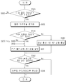
- step S600 the controller 170 determines whether the representative insulation resistance value is larger than a predetermined threshold resistance value (see RTH in Figs. 8 and 9).
- the representative insulation resistance value may be set to any one of the first insulation resistance value R Leak (+) and the second insulation resistance value R Leak (-) such as the first insulation resistance value R Leak (+) and the second insulation resistance value R Leak (-) may be the smaller one. If the value of the step S600 is "YES ", the step S605 proceeds. If the value of step S600 is NO, that is, if the representative insulation resistance value is equal to or less than the threshold resistance value, step S650 is performed.
- step S605 the controller 170 initializes the fault count.
- the fault count may be set to a specific value, such as zero, by initialization.
- the fault count may indicate the number of times that the representative insulation resistance value is continuously calculated to be equal to or less than the threshold resistance value.
- step S610 the controller 170 determines whether or not the insulation resistance value difference is smaller than a predetermined reference difference.
- the first insulation resistance value R Leak (+) Or the second insulation resistance value R Leak (-) may sharply decrease or increase toward the critical resistance value. Therefore, when the insulation resistance value difference is equal to or greater than the reference difference, it indicates that the representative insulation resistance value to be determined next time is equal to or less than the threshold resistance value.
- step S610 If the value of the step S610 is "YES ", the step S620 proceeds. If the value of the step S610 is "NO ", the step S630 is proceeded.
- step S620 the controller 170 assigns a first value (e.g., 0) to the diagnostic flag.
- the first value indicates that the representative insulation resistance value is valid. Also, the fact that the first value is assigned to the diagnostic flag may mean that the diagnostic flag is initialized.
- step S630 the controller 170 assigns a second value (e.g., 1) to the diagnostic flag.
- the second value indicates that the representative insulation resistance value is not valid.
- step S642 the controller 170 determines whether the second value is assigned to the diagnostic flag.
- the fact that the second value is assigned to the diagnosis flag means that the step S630 has been executed last time.
- the fact that the second value is not allocated to the diagnostic flag, that is, the first value is assigned means that Step S620 has been executed last time. If the value of the step S642 is "YES ", the step S644 proceeds. If the value of step S642 is "NO ", the method ends.
- step S644 the controller 170 activates the count indicator.
- step S650 can be performed when the value of step S600 is "NO ".
- the controller 170 increments the fault count. That is, the controller 170 increases the fault count every time it is determined that the representative insulation resistance value is equal to or smaller than the threshold resistance value.
- the fault count is a value updated every time in the controller 170, and indicates the number of times that the representative insulation resistance value is determined to be equal to or less than the threshold resistance value consecutively up to now.
- step S660 the controller 170 determines whether or not the count indicator is activated. If the value of the step S660 is "NO ", the step S670 proceeds. If the value of the step S660 is "YES ", the step S680 proceeds.
- step S670 if the count indicator is not activated, the controller 170 determines whether the increased fault flag is equal to or greater than a predetermined first count.
- step S650 if the fault count is programmed to increase by 1, the first count may be 2 or more (preferably 3 or more). If the value of step S670 is YES, step S690 is proceeded. If the value of step S670 is "NO ", the method according to Figs. 6 and 7 can be terminated.
- step S680 when the count indicator is activated, the controller 170 determines whether the increased fault flag is equal to or greater than a predetermined second count. At this time, the second count is smaller than the first count. For example, in step S650, if the fault count is programmed to increase by 1 and the first count is 10, the second count may be any one of 1 to 9. If the value of step S680 is YES, step S690 is proceeded. If the value of step S680 is "NO ", the method according to Figs. 6 and 7 can be terminated.
- step S690 the controller 170 executes a predetermined protection operation.
- the protection operation may include a notification of the insulation resistance value. That is, the controller 170 can transmit a signal indicating the first insulation resistance value R Leak (+) and the second insulation resistance value R Leak (- ) to the external device 30 through the communication unit 181.
- the protection operation may include a warning. That is, the controller 170 can output the warning message through the warning unit 182.
- the protection operation may include turning off the safety switch SW3. That is, the controller 170 can turn off the safety switch SW3 by using the switch driver 160.
- the representative insulation resistance value calculated at the time t i is based on V Bat , V 1 and V 2 measured in the time range of (t i -3 sec) to (t i -1 sec).
- the graph of Figure 8 shows an exemplary variation of the representative insulation resistance over time.
- the period from time T1 to time T2 represents a period during which insulation breakdown occurs between the battery 20 and the ground, or a period during which the voltage measuring unit 150 is temporarily faulty.
- the insulation resistance value calculated by the representative t 3 can not affected to the situation generated in the period from T1 to T2. Accordingly, the first count is utilized for battery shortage diagnosis.
- the representative of the insulation resistance value of the time t 3, time t 4, in response to the time t in succession three times ( first count) in the 5 that is below the threshold resistance value, the controller 170 may execute the protection operation .
- the graph of Figure 9 shows an exemplary variation of the representative insulation resistance over time.
- the period from the time point T3 to the time point T4 indicates a period during which the insulation breakdown occurs between the battery 20 and the ground, or a period during which the voltage measuring unit 150 is temporarily faulty.
- the time point T4 affected by the conditions generated in the period later than if the time (t 3 -3 sec), represented the insulation resistance value calculated at t 3 is from T3 to T4, t 2 the difference between the representative value and the insulation resistance represents insulation resistance value calculated at t 3 calculated in, that is, the insulation resistance difference ( ⁇ R) can be more than the reference difference.
- the controller 170 may execute the protection operation.
Landscapes
- Electrochemistry (AREA)
- General Chemical & Material Sciences (AREA)
- Chemical & Material Sciences (AREA)
- Chemical Kinetics & Catalysis (AREA)
- Physics & Mathematics (AREA)
- General Physics & Mathematics (AREA)
- Engineering & Computer Science (AREA)
- Manufacturing & Machinery (AREA)
- Microelectronics & Electronic Packaging (AREA)
- Testing Of Short-Circuits, Discontinuities, Leakage, Or Incorrect Line Connections (AREA)
- Secondary Cells (AREA)
- Electric Propulsion And Braking For Vehicles (AREA)
- Measurement Of Resistance Or Impedance (AREA)
Abstract
L'invention concerne un procédé et un appareil de détection d'un court-circuit de batterie. Un mode de réalisation de la présente invention concerne un procédé consistant : à déterminer si une différence de valeur de résistance d'isolation, constituant la différence entre une valeur de résistance d'isolation représentative précédente et une valeur de résistance d'isolation représentative, est inférieure à la différence de référence prédéterminée lorsque la valeur de résistance d'isolation représentative indiquant un état d'isolation entre une batterie et une mise à la terre est supérieure à la valeur de résistance de référence prédéterminée ; à attribuer une première valeur à un drapeau de diagnostic lorsque la différence de valeur de résistance d'isolation est inférieure à la différence de référence ; à attribuer une seconde valeur au drapeau de diagnostic lorsque la différence de valeur de résistance d'isolation est supérieure ou égale à la différence de référence ; et à activer un indicateur de comptage lorsque la seconde valeur est attribuée au drapeau de diagnostic. La première valeur indique que la valeur de résistance d'isolation représentative est valide. La seconde valeur indique que la valeur de résistance d'isolation représentative n'est pas valide.
Priority Applications (4)
| Application Number | Priority Date | Filing Date | Title |
|---|---|---|---|
| US16/626,411 US10985553B2 (en) | 2017-12-15 | 2018-12-07 | Method and apparatus for detecting battery leakage |
| CN201880037285.2A CN110709719B (zh) | 2017-12-15 | 2018-12-07 | 用于检测电池泄漏的方法和装置 |
| EP18887339.2A EP3674720B1 (fr) | 2017-12-15 | 2018-12-07 | Procédé et dispositif de détection de fuite de batterie |
| JP2019567968A JP6996813B2 (ja) | 2017-12-15 | 2018-12-07 | バッテリー漏電を検出するための方法及び装置 |
Applications Claiming Priority (2)
| Application Number | Priority Date | Filing Date | Title |
|---|---|---|---|
| KR10-2017-0173495 | 2017-12-15 | ||
| KR1020170173495A KR102259382B1 (ko) | 2017-12-15 | 2017-12-15 | 배터리 누전을 검출하기 위한 방법 및 장치 |
Publications (1)
| Publication Number | Publication Date |
|---|---|
| WO2019117556A1 true WO2019117556A1 (fr) | 2019-06-20 |
Family
ID=66820723
Family Applications (1)
| Application Number | Title | Priority Date | Filing Date |
|---|---|---|---|
| PCT/KR2018/015568 WO2019117556A1 (fr) | 2017-12-15 | 2018-12-07 | Procédé et dispositif de détection de court-circuit de batterie |
Country Status (6)
| Country | Link |
|---|---|
| US (1) | US10985553B2 (fr) |
| EP (1) | EP3674720B1 (fr) |
| JP (1) | JP6996813B2 (fr) |
| KR (1) | KR102259382B1 (fr) |
| CN (1) | CN110709719B (fr) |
| WO (1) | WO2019117556A1 (fr) |
Cited By (1)
| Publication number | Priority date | Publication date | Assignee | Title |
|---|---|---|---|---|
| EP3988372A4 (fr) * | 2019-10-29 | 2022-10-05 | LG Energy Solution, Ltd. | Dispositif de détection de courant de fuite, procédé de détection de courant de fuite et véhicule électrique |
Families Citing this family (18)
| Publication number | Priority date | Publication date | Assignee | Title |
|---|---|---|---|---|
| TWI662766B (zh) * | 2018-05-23 | 2019-06-11 | 車王電子股份有限公司 | Electric bus power system |
| CN109765495B (zh) * | 2019-01-15 | 2020-11-10 | 宁德时代新能源科技股份有限公司 | 绝缘检测电路及检测方法、电池管理系统 |
| KR102672495B1 (ko) * | 2019-03-15 | 2024-06-07 | 에스케이온 주식회사 | 절연저항 측정 장치 |
| FR3101425B1 (fr) * | 2019-09-30 | 2021-10-15 | Renault Sas | Procédé d’estimation de la résistance d’isolement d’un circuit haute tension d’un véhicule automobile électrique ou hybride |
| KR102701207B1 (ko) * | 2019-10-30 | 2024-08-29 | 주식회사 엘지에너지솔루션 | 배터리 절연 진단 장치 |
| KR102371743B1 (ko) * | 2019-11-25 | 2022-03-08 | 주식회사 현대케피코 | 세이프티 플러그 제어부를 포함하는 절연저항 제어장치 및 절연저항 제어장치 제어방법 |
| KR20210126860A (ko) | 2020-04-13 | 2021-10-21 | 에스케이이노베이션 주식회사 | 절연 저항 측정 장치 |
| KR102630834B1 (ko) * | 2020-05-15 | 2024-01-30 | 주식회사 엘지에너지솔루션 | 배터리를 진단하기 위한 장치 및 그 방법 |
| CN114152888B (zh) * | 2020-08-21 | 2023-03-31 | 比亚迪股份有限公司 | 动力电池绝缘检测方法、系统及车辆 |
| CN112083299B (zh) * | 2020-09-11 | 2023-05-26 | 国网重庆市电力公司北碚供电分公司 | 一种基于卡尔曼滤波的直流系统绝缘故障预测方法 |
| KR20220040613A (ko) | 2020-09-24 | 2022-03-31 | 에스케이온 주식회사 | 배터리의 특성 산출 장치 및 방법 |
| CN113471479A (zh) * | 2021-06-28 | 2021-10-01 | 三一汽车制造有限公司 | 燃料电池的控制方法、控制装置、燃料电池和存储介质 |
| US11637421B2 (en) * | 2021-07-09 | 2023-04-25 | Transportation Ip Holdings, Llc | Ground impedance and fault detection system and method |
| KR20230075236A (ko) * | 2021-11-22 | 2023-05-31 | 주식회사 엘지에너지솔루션 | 절연 저항을 측정하는 장치 및 이를 포함하는 배터리 시스템 |
| TWI789239B (zh) * | 2022-02-14 | 2023-01-01 | 瑞昱半導體股份有限公司 | 自動調整輸入訊號衰減程度的電壓監測系統與電壓監測裝置以及相關的電壓監測方法 |
| CN114670643B (zh) * | 2022-03-30 | 2023-05-23 | 重庆长安新能源汽车科技有限公司 | 一种绝缘故障诊断方法、装置、控制器及介质 |
| KR20240101171A (ko) * | 2022-12-23 | 2024-07-02 | 주식회사 엘지에너지솔루션 | 배터리 팩, 배터리 장치 및 전해액 누설 검출 방법 |
| CN115951127B (zh) * | 2023-02-10 | 2023-09-12 | 小米汽车科技有限公司 | 车载充电电路的绝缘电阻检测方法、车载充电电路及介质 |
Citations (5)
| Publication number | Priority date | Publication date | Assignee | Title |
|---|---|---|---|---|
| KR20030010582A (ko) * | 2000-02-22 | 2003-02-05 | 산요 덴키 가부시키가이샤 | 전원 장치의 누전 검출 회로 |
| JP2003066090A (ja) * | 2001-08-29 | 2003-03-05 | Omron Corp | 漏電検出装置 |
| JP2009093822A (ja) * | 2007-10-04 | 2009-04-30 | Toyota Industries Corp | 燃料電池システムの漏電検出装置 |
| KR101371854B1 (ko) * | 2012-08-01 | 2014-03-24 | 기아자동차주식회사 | 절연저항측정센서를 이용한 차량의 누전진단장치 및 이의 제어방법 |
| JP2016128753A (ja) * | 2015-01-09 | 2016-07-14 | 株式会社デンソー | 漏電判定装置 |
Family Cites Families (30)
| Publication number | Priority date | Publication date | Assignee | Title |
|---|---|---|---|---|
| JP2001045652A (ja) | 1999-07-30 | 2001-02-16 | Matsushita Electric Works Ltd | アーク検出器 |
| JP2004245600A (ja) * | 2003-02-10 | 2004-09-02 | Yazaki Corp | 絶縁抵抗検出装置 |
| JP4082676B2 (ja) | 2003-05-29 | 2008-04-30 | 株式会社デンソー | 漏電検出装置の検査システム |
| JP2007300753A (ja) | 2006-05-01 | 2007-11-15 | Nissan Motor Co Ltd | 絶縁抵抗検出システム |
| EP2322945B1 (fr) | 2008-08-11 | 2014-11-26 | LG Chem, Ltd. | Appareil et procédé permettant la détection de courant de fuite de batteries, et appareil de commande de batteries et bloc de batteries comportant l'appareil |
| KR100958795B1 (ko) | 2008-09-01 | 2010-05-18 | 주식회사 엘지화학 | 배터리 누설전류 감지 장치 및 방법, 및 상기 장치를 포함하는 배터리 구동 장치 및 배터리 팩 |
| JP5381467B2 (ja) | 2009-07-30 | 2014-01-08 | トヨタ自動車株式会社 | 駆動装置およびその絶縁抵抗低下箇所判定方法並びに車両 |
| JP5515532B2 (ja) * | 2009-09-07 | 2014-06-11 | コベルコ建機株式会社 | 建設機械の漏電検出装置 |
| WO2012122131A2 (fr) | 2011-03-04 | 2012-09-13 | Paceco Corp | Mesure de résistance d'isolement de panneaux photovoltaïques configurables dans réseau de panneaux photovoltaïques |
| JP5736197B2 (ja) * | 2011-03-09 | 2015-06-17 | 矢崎総業株式会社 | 絶縁状態検出ユニット |
| JP5808678B2 (ja) | 2012-01-18 | 2015-11-10 | 本田技研工業株式会社 | 電動車両 |
| US9217690B2 (en) * | 2012-01-25 | 2015-12-22 | GM Global Technology Operations LLC | Coolant loss detection and remediation in a liquid cooled battery pack |
| JP5474114B2 (ja) * | 2012-03-16 | 2014-04-16 | 三菱電機株式会社 | 車載高電圧機器の漏電抵抗検出装置およびその漏電抵抗検出方法 |
| PL2720056T3 (pl) | 2012-04-04 | 2021-07-12 | Lg Chem, Ltd. | Urządzenie do mierzenia rezystancji izolacji, mające funkcję samodiagnozowania usterek, oraz wykorzystujący je sposób samodiagnozowania |
| CN202710661U (zh) * | 2012-07-16 | 2013-01-30 | 山东奥太电气有限公司 | 一种应用于光伏逆变系统的直流接地电阻检测电路 |
| JP5642737B2 (ja) | 2012-07-25 | 2014-12-17 | 中国電力株式会社 | 絶縁診断装置、絶縁診断システム、プログラム |
| CN102854395B (zh) * | 2012-09-04 | 2015-10-21 | 阳光电源(上海)有限公司 | 一种直流电源对地绝缘电阻检测电路及其检测方法 |
| CN103389444B (zh) * | 2013-07-24 | 2016-02-03 | 中达电通股份有限公司 | 基于电压预测的投切式绝缘监测误差自适应方法 |
| CN103389436B (zh) * | 2013-07-24 | 2015-12-02 | 中达电通股份有限公司 | 直流供电系统的投切式绝缘监测方法及系统 |
| DE102013013950B4 (de) * | 2013-08-21 | 2020-08-06 | Audi Ag | Verfahren, Messanordnung und Messgerät zur Bestimmung von lsolationswiderständen von Einzelzellen einer Hochvoltbatterie |
| KR101512395B1 (ko) | 2013-10-08 | 2015-04-16 | 현대오트론 주식회사 | 절연저항 측정 장치 및 방법 |
| FR3014206B1 (fr) | 2013-12-04 | 2015-12-11 | Renault Sas | Estimation de la resistance d'isolement entre une batterie de vehicule automobile et la masse |
| US9194918B2 (en) | 2013-12-12 | 2015-11-24 | Ford Global Technologies, Llc | Leakage detection circuit with integral circuit robustness check |
| KR101771226B1 (ko) * | 2014-10-02 | 2017-09-05 | 주식회사 엘지화학 | 신속하게 절연 저항을 측정할 수 있는 절연 저항 측정 장치 및 방법 |
| US9758044B2 (en) * | 2014-10-02 | 2017-09-12 | Ford Global Technologies, Llc | Bus leakage resistance estimation for electrical isolation testing and diagnostics |
| KR20160069800A (ko) | 2014-12-09 | 2016-06-17 | 현대오트론 주식회사 | 배터리 관리 시스템의 누설 전류 검출 장치 및 방법 |
| JP6417256B2 (ja) | 2015-03-30 | 2018-11-07 | 東洋電機製造株式会社 | 電動機駆動装置 |
| KR101735739B1 (ko) | 2015-12-15 | 2017-05-15 | 현대오트론 주식회사 | 누설 전류 진단 장치 및 방법 |
| CN106154114A (zh) * | 2016-08-03 | 2016-11-23 | 四川网达科技有限公司 | 故障测试装置与方法 |
| KR102654840B1 (ko) * | 2018-12-07 | 2024-04-05 | 현대자동차주식회사 | Obc, 이를 포함하는 차량 및 이의 동작 방법 |
-
2017
- 2017-12-15 KR KR1020170173495A patent/KR102259382B1/ko active IP Right Grant
-
2018
- 2018-12-07 EP EP18887339.2A patent/EP3674720B1/fr active Active
- 2018-12-07 JP JP2019567968A patent/JP6996813B2/ja active Active
- 2018-12-07 WO PCT/KR2018/015568 patent/WO2019117556A1/fr unknown
- 2018-12-07 CN CN201880037285.2A patent/CN110709719B/zh active Active
- 2018-12-07 US US16/626,411 patent/US10985553B2/en active Active
Patent Citations (5)
| Publication number | Priority date | Publication date | Assignee | Title |
|---|---|---|---|---|
| KR20030010582A (ko) * | 2000-02-22 | 2003-02-05 | 산요 덴키 가부시키가이샤 | 전원 장치의 누전 검출 회로 |
| JP2003066090A (ja) * | 2001-08-29 | 2003-03-05 | Omron Corp | 漏電検出装置 |
| JP2009093822A (ja) * | 2007-10-04 | 2009-04-30 | Toyota Industries Corp | 燃料電池システムの漏電検出装置 |
| KR101371854B1 (ko) * | 2012-08-01 | 2014-03-24 | 기아자동차주식회사 | 절연저항측정센서를 이용한 차량의 누전진단장치 및 이의 제어방법 |
| JP2016128753A (ja) * | 2015-01-09 | 2016-07-14 | 株式会社デンソー | 漏電判定装置 |
Non-Patent Citations (1)
| Title |
|---|
| See also references of EP3674720A4 |
Cited By (2)
| Publication number | Priority date | Publication date | Assignee | Title |
|---|---|---|---|---|
| EP3988372A4 (fr) * | 2019-10-29 | 2022-10-05 | LG Energy Solution, Ltd. | Dispositif de détection de courant de fuite, procédé de détection de courant de fuite et véhicule électrique |
| US11762022B2 (en) | 2019-10-29 | 2023-09-19 | Lg Energy Solution, Ltd. | Electric leakage detection apparatus, electric leakage detection method, and electric vehicle |
Also Published As
| Publication number | Publication date |
|---|---|
| CN110709719B (zh) | 2021-12-07 |
| KR20190072272A (ko) | 2019-06-25 |
| CN110709719A (zh) | 2020-01-17 |
| EP3674720B1 (fr) | 2023-07-19 |
| EP3674720A4 (fr) | 2020-12-02 |
| KR102259382B1 (ko) | 2021-06-01 |
| US10985553B2 (en) | 2021-04-20 |
| JP6996813B2 (ja) | 2022-01-17 |
| JP2020523576A (ja) | 2020-08-06 |
| EP3674720A1 (fr) | 2020-07-01 |
| US20200144812A1 (en) | 2020-05-07 |
Similar Documents
| Publication | Publication Date | Title |
|---|---|---|
| WO2019117556A1 (fr) | Procédé et dispositif de détection de court-circuit de batterie | |
| WO2016052900A1 (fr) | Procédé et dispositif pour estimer la puissance de décharge d'une batterie secondaire | |
| WO2020005020A1 (fr) | Système de gestion de batterie, bloc-batterie le comprenant et procédé de détermination de défaut pour circuit de mesure de courant | |
| WO2013151355A1 (fr) | Dispositif de mesure d'une résistance d'isolement doté d'une fonction d'autodiagnostic de défaillance et procédé d'autodiagnostic l'utilisant | |
| WO2017142385A1 (fr) | Appareil et procédé pour diagnostiquer une défaillance d'un composant de commutation | |
| WO2021085893A1 (fr) | Appareil de détection de court-circuit, procédé de détection de court-circuit et véhicule électrique | |
| WO2013147494A1 (fr) | Dispositif et procédé de mesure de la résistance d'isolement d'une batterie | |
| WO2018070684A2 (fr) | Dispositif de diagnostic et système d'alimentation électrique le comprenant | |
| WO2019117606A1 (fr) | Dispositif et procédé de diagnostic d'un contacteur d'électrode positive d'un bloc-batterie | |
| WO2020153637A1 (fr) | Dispositif de gestion de batterie, procédé de gestion de batterie et bloc-batterie | |
| WO2019151779A1 (fr) | Appareil de protection de résistance de précharge | |
| WO2019117607A1 (fr) | Dispositif et procédé de diagnostic de contacteur d'électrode négative de bloc-batterie | |
| WO2021080161A1 (fr) | Système de gestion de batterie, bloc-batterie, véhicule électrique et procédé de gestion de batterie | |
| EP2321663A1 (fr) | Appareil et procédé pour estimer l'état de santé d'une batterie en fonction d'un motif de variation de tension de batterie | |
| WO2020017817A1 (fr) | Dispositif et procédé de diagnostic de commutateur | |
| WO2020162675A1 (fr) | Appareil de gestion de batterie, procédé de gestion de batterie et batterie | |
| WO2014084628A1 (fr) | Appareil de mesure de courant de batterie et procédé associé | |
| WO2020055117A1 (fr) | Dispositif de gestion de batterie | |
| WO2022030971A1 (fr) | Dispositif de diagnostic de batterie, bloc-batterie, système de batterie et procédé de diagnostic de batterie | |
| WO2022098096A1 (fr) | Dispositif et procédé de diagnostic de batterie | |
| WO2019107976A1 (fr) | Bloc batterie | |
| WO2022145822A1 (fr) | Appareil et procédé de gestion de batterie | |
| WO2018074744A1 (fr) | Dispositif et procédé de diagnostic d'un commutateur à l'aide d'une distribution de tension | |
| WO2019107979A1 (fr) | Bloc batterie | |
| WO2019117555A1 (fr) | Dispositif et procédé de prévention de court-circuit |
Legal Events
| Date | Code | Title | Description |
|---|---|---|---|
| 121 | Ep: the epo has been informed by wipo that ep was designated in this application |
Ref document number: 18887339 Country of ref document: EP Kind code of ref document: A1 |
|
| ENP | Entry into the national phase |
Ref document number: 2019567968 Country of ref document: JP Kind code of ref document: A |
|
| ENP | Entry into the national phase |
Ref document number: 2018887339 Country of ref document: EP Effective date: 20200324 |
|
| NENP | Non-entry into the national phase |
Ref country code: DE |