WO2019116994A1 - 画像補正装置、画像補正方法およびプログラム - Google Patents
画像補正装置、画像補正方法およびプログラム Download PDFInfo
- Publication number
- WO2019116994A1 WO2019116994A1 PCT/JP2018/044798 JP2018044798W WO2019116994A1 WO 2019116994 A1 WO2019116994 A1 WO 2019116994A1 JP 2018044798 W JP2018044798 W JP 2018044798W WO 2019116994 A1 WO2019116994 A1 WO 2019116994A1
- Authority
- WO
- WIPO (PCT)
- Prior art keywords
- image
- time
- mounted display
- head mounted
- attitude
- Prior art date
Links
- 238000003702 image correction Methods 0.000 title claims description 44
- 238000000034 method Methods 0.000 title claims description 20
- 238000012937 correction Methods 0.000 claims abstract description 15
- 230000033001 locomotion Effects 0.000 claims description 23
- 238000001514 detection method Methods 0.000 claims description 5
- 230000005540 biological transmission Effects 0.000 abstract description 12
- 230000000007 visual effect Effects 0.000 description 21
- 238000012545 processing Methods 0.000 description 16
- 238000004891 communication Methods 0.000 description 14
- 238000010586 diagram Methods 0.000 description 14
- 230000006870 function Effects 0.000 description 8
- 238000009877 rendering Methods 0.000 description 8
- 230000001133 acceleration Effects 0.000 description 4
- 239000011521 glass Substances 0.000 description 3
- 238000007654 immersion Methods 0.000 description 2
- 206010025482 malaise Diseases 0.000 description 2
- 238000012986 modification Methods 0.000 description 2
- 230000004048 modification Effects 0.000 description 2
- 238000004364 calculation method Methods 0.000 description 1
- 238000006243 chemical reaction Methods 0.000 description 1
- 238000004590 computer program Methods 0.000 description 1
- 230000001934 delay Effects 0.000 description 1
- 230000003111 delayed effect Effects 0.000 description 1
- 230000000694 effects Effects 0.000 description 1
- 230000002708 enhancing effect Effects 0.000 description 1
- 230000002093 peripheral effect Effects 0.000 description 1
Images


Classifications
-
- G—PHYSICS
- G02—OPTICS
- G02B—OPTICAL ELEMENTS, SYSTEMS OR APPARATUS
- G02B27/00—Optical systems or apparatus not provided for by any of the groups G02B1/00 - G02B26/00, G02B30/00
- G02B27/01—Head-up displays
- G02B27/017—Head mounted
- G02B27/0172—Head mounted characterised by optical features
-
- G—PHYSICS
- G02—OPTICS
- G02B—OPTICAL ELEMENTS, SYSTEMS OR APPARATUS
- G02B27/00—Optical systems or apparatus not provided for by any of the groups G02B1/00 - G02B26/00, G02B30/00
- G02B27/01—Head-up displays
- G02B27/017—Head mounted
-
- G—PHYSICS
- G02—OPTICS
- G02B—OPTICAL ELEMENTS, SYSTEMS OR APPARATUS
- G02B27/00—Optical systems or apparatus not provided for by any of the groups G02B1/00 - G02B26/00, G02B30/00
- G02B27/0093—Optical systems or apparatus not provided for by any of the groups G02B1/00 - G02B26/00, G02B30/00 with means for monitoring data relating to the user, e.g. head-tracking, eye-tracking
-
- G—PHYSICS
- G02—OPTICS
- G02B—OPTICAL ELEMENTS, SYSTEMS OR APPARATUS
- G02B27/00—Optical systems or apparatus not provided for by any of the groups G02B1/00 - G02B26/00, G02B30/00
- G02B27/01—Head-up displays
- G02B27/0179—Display position adjusting means not related to the information to be displayed
-
- G—PHYSICS
- G06—COMPUTING; CALCULATING OR COUNTING
- G06F—ELECTRIC DIGITAL DATA PROCESSING
- G06F3/00—Input arrangements for transferring data to be processed into a form capable of being handled by the computer; Output arrangements for transferring data from processing unit to output unit, e.g. interface arrangements
- G06F3/01—Input arrangements or combined input and output arrangements for interaction between user and computer
- G06F3/011—Arrangements for interaction with the human body, e.g. for user immersion in virtual reality
- G06F3/012—Head tracking input arrangements
-
- G—PHYSICS
- G06—COMPUTING; CALCULATING OR COUNTING
- G06F—ELECTRIC DIGITAL DATA PROCESSING
- G06F3/00—Input arrangements for transferring data to be processed into a form capable of being handled by the computer; Output arrangements for transferring data from processing unit to output unit, e.g. interface arrangements
- G06F3/14—Digital output to display device ; Cooperation and interconnection of the display device with other functional units
- G06F3/147—Digital output to display device ; Cooperation and interconnection of the display device with other functional units using display panels
-
- H—ELECTRICITY
- H04—ELECTRIC COMMUNICATION TECHNIQUE
- H04N—PICTORIAL COMMUNICATION, e.g. TELEVISION
- H04N21/00—Selective content distribution, e.g. interactive television or video on demand [VOD]
- H04N21/40—Client devices specifically adapted for the reception of or interaction with content, e.g. set-top-box [STB]; Operations thereof
- H04N21/43—Processing of content or additional data, e.g. demultiplexing additional data from a digital video stream; Elementary client operations, e.g. monitoring of home network or synchronising decoder's clock; Client middleware
- H04N21/431—Generation of visual interfaces for content selection or interaction; Content or additional data rendering
- H04N21/4318—Generation of visual interfaces for content selection or interaction; Content or additional data rendering by altering the content in the rendering process, e.g. blanking, blurring or masking an image region
-
- H—ELECTRICITY
- H04—ELECTRIC COMMUNICATION TECHNIQUE
- H04N—PICTORIAL COMMUNICATION, e.g. TELEVISION
- H04N21/00—Selective content distribution, e.g. interactive television or video on demand [VOD]
- H04N21/40—Client devices specifically adapted for the reception of or interaction with content, e.g. set-top-box [STB]; Operations thereof
- H04N21/43—Processing of content or additional data, e.g. demultiplexing additional data from a digital video stream; Elementary client operations, e.g. monitoring of home network or synchronising decoder's clock; Client middleware
- H04N21/442—Monitoring of processes or resources, e.g. detecting the failure of a recording device, monitoring the downstream bandwidth, the number of times a movie has been viewed, the storage space available from the internal hard disk
- H04N21/44213—Monitoring of end-user related data
- H04N21/44218—Detecting physical presence or behaviour of the user, e.g. using sensors to detect if the user is leaving the room or changes his face expression during a TV program
-
- H—ELECTRICITY
- H04—ELECTRIC COMMUNICATION TECHNIQUE
- H04N—PICTORIAL COMMUNICATION, e.g. TELEVISION
- H04N21/00—Selective content distribution, e.g. interactive television or video on demand [VOD]
- H04N21/40—Client devices specifically adapted for the reception of or interaction with content, e.g. set-top-box [STB]; Operations thereof
- H04N21/47—End-user applications
- H04N21/478—Supplemental services, e.g. displaying phone caller identification, shopping application
- H04N21/4781—Games
-
- H—ELECTRICITY
- H04—ELECTRIC COMMUNICATION TECHNIQUE
- H04N—PICTORIAL COMMUNICATION, e.g. TELEVISION
- H04N21/00—Selective content distribution, e.g. interactive television or video on demand [VOD]
- H04N21/80—Generation or processing of content or additional data by content creator independently of the distribution process; Content per se
- H04N21/81—Monomedia components thereof
- H04N21/816—Monomedia components thereof involving special video data, e.g 3D video
-
- G—PHYSICS
- G02—OPTICS
- G02B—OPTICAL ELEMENTS, SYSTEMS OR APPARATUS
- G02B27/00—Optical systems or apparatus not provided for by any of the groups G02B1/00 - G02B26/00, G02B30/00
- G02B27/01—Head-up displays
- G02B27/0101—Head-up displays characterised by optical features
- G02B2027/0138—Head-up displays characterised by optical features comprising image capture systems, e.g. camera
-
- G—PHYSICS
- G02—OPTICS
- G02B—OPTICAL ELEMENTS, SYSTEMS OR APPARATUS
- G02B27/00—Optical systems or apparatus not provided for by any of the groups G02B1/00 - G02B26/00, G02B30/00
- G02B27/01—Head-up displays
- G02B27/0101—Head-up displays characterised by optical features
- G02B2027/014—Head-up displays characterised by optical features comprising information/image processing systems
-
- G—PHYSICS
- G02—OPTICS
- G02B—OPTICAL ELEMENTS, SYSTEMS OR APPARATUS
- G02B27/00—Optical systems or apparatus not provided for by any of the groups G02B1/00 - G02B26/00, G02B30/00
- G02B27/01—Head-up displays
- G02B27/017—Head mounted
- G02B2027/0178—Eyeglass type
-
- G—PHYSICS
- G02—OPTICS
- G02B—OPTICAL ELEMENTS, SYSTEMS OR APPARATUS
- G02B27/00—Optical systems or apparatus not provided for by any of the groups G02B1/00 - G02B26/00, G02B30/00
- G02B27/01—Head-up displays
- G02B27/0179—Display position adjusting means not related to the information to be displayed
- G02B2027/0187—Display position adjusting means not related to the information to be displayed slaved to motion of at least a part of the body of the user, e.g. head, eye
-
- G—PHYSICS
- G09—EDUCATION; CRYPTOGRAPHY; DISPLAY; ADVERTISING; SEALS
- G09G—ARRANGEMENTS OR CIRCUITS FOR CONTROL OF INDICATING DEVICES USING STATIC MEANS TO PRESENT VARIABLE INFORMATION
- G09G2354/00—Aspects of interface with display user
-
- G—PHYSICS
- G09—EDUCATION; CRYPTOGRAPHY; DISPLAY; ADVERTISING; SEALS
- G09G—ARRANGEMENTS OR CIRCUITS FOR CONTROL OF INDICATING DEVICES USING STATIC MEANS TO PRESENT VARIABLE INFORMATION
- G09G2370/00—Aspects of data communication
- G09G2370/02—Networking aspects
- G09G2370/022—Centralised management of display operation, e.g. in a server instead of locally
Definitions
- the present invention relates to an apparatus and method for generating and correcting an image.
- a head mounted display connected to a game machine is mounted on a head, and while watching a screen displayed on the head mounted display, game play is performed by operating a controller or the like.
- the head mounted display is attached, the user can not see anything other than the image displayed on the head mounted display, so the sense of immersion in the image world is enhanced, and the effect of further enhancing the entertainment of the game can be obtained.
- an image of Virtual Reality is displayed on the head mounted display, and a user wearing the head mounted display rotates the head, a virtual space with 360 degree view can be displayed. Immersion to the image is enhanced, and the operability of applications such as games is also improved.
- a head mounted display is provided with a head tracking function
- a virtual reality image is generated by changing the viewpoint and the gaze direction in conjunction with the movement of the head of the user, from generation of a virtual reality image to display Since there is a delay, a gap occurs between the direction of the user's head assumed when generating the image and the direction of the user's head when the image is displayed on the head mounted display, and the user seems drunk May fall into a sense (called "Virtual Reality Sickness" or the like).
- the present invention has been made in view of these problems, and an object thereof is to provide an image correction technique capable of correcting an image according to the delay from generation to distribution and display of the image.
- an image correction apparatus acquires an image drawn based on the position or orientation of a head mounted display at a first time along with information on the position or orientation of the first time Information on the position or attitude of the head mount display at the second time when the image is displayed, and the difference between the position or attitude at the first time and the position or attitude at the second time
- a correction unit that corrects the image by translating or rotating the field of view of the screen coordinate system of the head mounted display and attaching the image as a texture to the field of view after the parallel or rotating movement.
- Another aspect of the present invention is an image correction method.
- This method comprises an acquisition step of acquiring an image drawn based on the position or attitude of the head mounted display at a first time together with information of the position or attitude at the first time, and a second time when the image is displayed Information of the position or attitude of the head mounted display, and translating or changing the field of view of the screen coordinate system of the head mounted display according to the difference between the position or attitude at the first time and the position or attitude at the second time And correcting the image by rotationally moving and pasting the image as a texture to the field of view after parallel movement or rotational movement.
- FIG. 1 is a configuration diagram of an image generation system according to the present embodiment. It is a function block diagram of a head mounted display. It is a functional block diagram of the image generation apparatus concerning this Embodiment. It is a functional block diagram of the image correction apparatus which concerns on this Embodiment. It is a flowchart explaining the image generation procedure of this Embodiment. It is a detailed time chart of an image generation procedure of this embodiment. 8 (a) to 8 (c) are diagrams for explaining the rotational movement of the billboard. It is a figure explaining the rotational movement of a billboard in detail. It is a figure explaining the projection to the screen of the billboard after rotation.
- FIG. 1 is an external view of a head mounted display 100.
- the head mounted display 100 is a display device mounted on the head of the user for viewing still images, moving images, and the like displayed on the display and listening to sounds, music, and the like output from headphones.
- a camera unit is mounted on the head mounted display 100, and while the user is wearing the head mounted display 100, the outside world can be photographed.
- the head mounted display 100 is an example of a “wearable display”.
- a method of generating an image displayed on the head mounted display 100 will be described.
- the method of generating an image according to the present embodiment is not limited to the head mounted display 100 in a narrow sense, but a glasses, glasses type display, glasses type camera, It can also be applied when wearing headphones, headsets (headphones with microphones), earphones, earrings, earpiece cameras, hats, camera hats, hair bands etc.
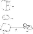
- FIG. 2 is a block diagram of an image generation system according to the present embodiment.
- the head mounted display 100 is connected to the image correction device 200 by an interface 300 such as HDMI (High-Definition Multimedia Interface), which is a standard of a communication interface for transmitting video and audio as digital signals, as an example. .
- HDMI High-Definition Multimedia Interface
- An example of the image correction apparatus 200 is a game machine.
- the image correction device 200 is connected to the image generation device 500 via the network 400.
- the image correction apparatus 200 is a client, and the image generation apparatus 500 is a server.
- the image generation apparatus 500 may provide the image correction apparatus 200 with an online application such as a game in which a plurality of users can participate via a network.
- the image correction device 200 transmits the position / attitude information of the head mounted display 100 to the image generation device 500.
- the image generation apparatus 500 draws an image to be displayed on the head mounted display 100 based on the received position / attitude information of the head mounted display 100, encodes the drawing data, and transmits it to the image correction apparatus 200 as a video stream. Do.
- the image correction apparatus 200 decodes the received video stream, corrects the drawing data in accordance with the latest position and orientation of the head mounted display 100, and displays the corrected data on the head mounted display 100.
- FIG. 3 is a functional block diagram of the head mounted display 100. As shown in FIG.
- the control unit 10 is a main processor that processes and outputs signals such as image signals and sensor signals, and instructions and data.
- the input interface 20 receives an operation signal and a setting signal from the user and supplies the control unit 10 with the operation signal and the setting signal.
- the output interface 30 receives an image signal from the control unit 10 and displays it on the display panel 32.
- the communication control unit 40 transmits data input from the control unit 10 to the outside through wired or wireless communication via the network adapter 42 or the antenna 44.
- the communication control unit 40 also receives data from the outside by wired or wireless communication via the network adapter 42 or the antenna 44, and outputs the data to the control unit 10.
- the storage unit 50 temporarily stores data to be processed by the control unit 10, parameters, operation signals and the like.
- the attitude sensor 64 detects position information of the head mounted display 100 and attitude information such as a rotation angle or tilt of the head mounted display 100.
- the attitude sensor 64 is realized by appropriately combining a gyro sensor, an acceleration sensor, an angular acceleration sensor, and the like.
- a motion sensor combining at least one or more of a three-axis geomagnetic sensor, a three-axis acceleration sensor, and a three-axis gyro (angular velocity) sensor may be used to detect front / rear, left / right, up / down motion of the user's head.
- the external input / output terminal interface 70 is an interface for connecting peripheral devices such as a USB (Universal Serial Bus) controller.
- the external memory 72 is an external memory such as a flash memory.
- the HDMI transmitting and receiving unit 90 transmits and receives digital signals of video and audio to and from the image correction apparatus 200 according to the HDMI.
- the HDMI transmitting and receiving unit 90 receives an image generated by the image correction apparatus 200 from the image correction apparatus 200 through the HDMI transmission path, and supplies the image to the control unit 10.
- the control unit 10 can supply an image or text data to the output interface 30 for display on the display panel 32, or can supply the image or text data to the communication control unit 40 to be transmitted to the outside.
- the current position / attitude information of the head mounted display 100 detected by the attitude sensor 64 is notified to the image correction apparatus 200 via the communication control unit 40 or the external input / output terminal interface 70.
- the HDMI transmitting / receiving unit 90 may transmit the current position / attitude information of the head mounted display 100 to the image correction apparatus 200.
- FIG. 4 is a functional configuration diagram of an image generation apparatus 500 according to the present embodiment.
- the figure depicts a block diagram focusing on functions, and these functional blocks can be realized in various forms by hardware only, software only, or a combination thereof.
- At least a part of the functions of the image generation device 500 may be implemented in the image correction device 200.
- the transmission / reception unit 560 receives the current position (or “first time”) position / attitude information of the head mounted display 100 from the image correction apparatus 200 and supplies the position / attitude acquisition unit 510 with the information.
- the viewpoint and line of sight setting unit 520 sets the viewpoint position and the line of sight direction of the user using the position and orientation information of the head mounted display 100 at the first time acquired by the position and orientation acquisition unit 510.
- the rendering unit 530 renders an object in a virtual space viewed from the viewpoint position of the user wearing the head mounted display 100 according to the viewpoint position and the gaze direction of the user set by the viewpoint / visual axis setting unit 520, It is stored in the storage unit 540.
- the encoding unit 550 encodes the rendering result stored in the image storage unit 540, and supplies the encoded video stream to the transmission / reception unit 560.
- the transmitting / receiving unit 560 receives the position / attitude information of the head mounted display 100 at the first time used for drawing by the rendering unit 530 from the position / attitude acquiring unit 510, and combines the video stream data with the position / attitude information at the first time. It is transmitted to the image correction apparatus 200.
- a video stream in which video data and position / posture information are associated in frame units is distributed from the image generation apparatus 500 as a server to the image correction apparatus 200 as a client.
- FIG. 5 is a functional configuration diagram of the image correction device 200 according to the present embodiment.
- the figure depicts a block diagram focusing on functions, and these functional blocks can be realized in various forms by hardware only, software only, or a combination thereof.
- At least a part of the functions of the image correction apparatus 200 may be implemented in the control unit 10 of the head mounted display 100.
- the transmitting / receiving unit 210 receives the video stream data and the position / attitude information of the head mounted display 100 at the first time used for drawing from the image generation apparatus 500 in frame units.
- the transmitting and receiving unit 210 supplies the received video stream data to the decoding unit 220, and supplies the position and orientation information of the head mounted display 100 at the first time to the position and orientation acquiring unit 230.
- the decoding unit 220 decodes the video stream data, and stores the decoded image in the image storage unit 250 together with the position / attitude information of the first time.
- the HDMI transmitting / receiving unit 270 receives the latest (referred to as “second time”) position / attitude information from the head mounted display 100 and supplies the position / attitude acquiring unit 230 with the position / attitude information.
- the position / posture acquisition unit 230 supplies the position / posture information of the first time and the position / posture information of the second time to the correction unit 260.
- the correction unit 260 reads the decoded image from the image storage unit 250, performs reprojection processing for correcting the image data in accordance with the difference between the position and orientation information at the first time and the position and orientation information at the second time, and mounts the head It is converted into an image viewed from the latest viewpoint position and line of sight of the display 100.
- the correction unit 260 supplies the corrected image data to the HDMI transmitting and receiving unit 270, and the HDMI transmitting and receiving unit 270 transmits the corrected image data to the head mounted display 100.
- the error detection unit 240 detects, as an error, a case where the video stream data is delayed due to congestion of the network or the like, and the transmission / reception unit 210 can not receive the video stream data required at the frame drawing timing.
- the error detection unit 240 notifies the correction unit 260 that an error has occurred.
- the correction unit 260 reads the decoded image of the immediately preceding frame from the image storage unit 250, and the position / attitude of the past time used to draw the decoded image of the immediately preceding frame. Performs reprojection processing that corrects the decoded image of the previous frame according to the difference between the information and the position and orientation information at the second time, and converts it into an image viewed from the latest viewpoint position and line of sight of the head mounted display 100 .
- the movement of the head mounted display 100 is detected, the CPU issues a drawing command, the GPU (Graphics Processing Unit) executes rendering, and the drawn image is output to the head mounted display 100.
- draw is performed at a frame rate of, for example, 60 fps (frames / second), and there is a delay of one frame from detection of movement of the head mounted display 100 to output of an image. This is about 16.67 ms at a frame rate of 60 fps, which is a sufficient time for a human to detect a shift.
- image data rendered by the server is encoded and transmitted to the client via the network, communication time is added to the time required for rendering, which causes a further delay before being displayed on the head mounted display 100.
- time warp or “reprojection” is performed to correct the rendered image in accordance with the latest position and posture of the head mounted display 100 so that it is difficult for a human to detect a deviation.
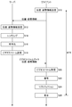
- FIG. 6 is a flowchart for explaining an image generation procedure of the present embodiment.
- the transmission / reception unit 210 of the image correction apparatus 200 as a client transmits the current position / attitude information of the head mounted display 100 to the image generation apparatus 500 as a server (S10).
- the transmission / reception unit 560 receives the current position / attitude information of the head mounted display 100 from the image correction device 200 (S12).
- the rendering unit 530 renders an image to be displayed on the head mounted display 100 based on the current position / attitude information of the head mounted display 100 (S14).
- the encoding unit 550 encodes the image data of the rendering result (S16).
- the transmission / reception unit 560 transmits the encoded video stream to the image correction apparatus 200 together with the position / attitude information of the head mounted display 100 used for drawing (S18).
- the transmission / reception unit 210 receives, from the image generation apparatus 500, the position / attitude information of the head mounted display 100 used for the video stream and the drawing (S20).
- the decoding unit 220 decodes the video stream (S22).
- the correction unit 260 executes a reprojection process to correct the drawing data in accordance with the latest position and orientation of the head mounted display 100 (S24).
- the HDMI transmitting and receiving unit 270 transmits the image data after correction to the head mounted display 100, and causes the head mounted display 100 to display the image data (S26).
- step S10 After the image correction apparatus 200 transmits the position and orientation information of the head mounted display 100 to the image generating apparatus 500 in step S10, a delay of round trip time (RTT) from when the image is displayed on the head mounted display 100 occurs. .
- RTT round trip time
- the reprojection process in step S24 interpolates the image so that the delay is not felt by the user.
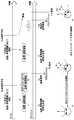
- FIG. 7 is a detailed time chart of the image generation procedure of the present embodiment.
- the image correction apparatus 200 which is a client, acquires the position and orientation information of the head mounted display 100, and transmits the acquired information to the image generation apparatus 500, which is a server.
- the image generation apparatus 500 draws an image to be displayed on the head mounted display 100 according to the received position and orientation information of the head mounted display 100.
- the image generation apparatus 500 encodes the drawn image, and transmits the encoded video stream data to the image correction apparatus 200 together with the position / attitude information of the head mounted display 100 used for drawing.
- the image correction apparatus 200 decodes the received video stream.
- the image correction apparatus 200 performs reprojection processing on the decoded image.
- the decoded image is drawn based on the position / attitude information of the head mounted display 100 at time T1.
- the image correction apparatus 200 causes the head mounted display 100 to display the decoded image subjected to the reprojection processing.
- the image correction apparatus 200 acquires position / posture information of the head mounted display 100, and transmits the acquired information to the image generation apparatus 500.
- the image generation apparatus 500 draws an image to be displayed on the head mounted display 100 according to the received position and orientation information of the head mounted display 100.
- the image generation apparatus 500 encodes the drawn image and transmits the encoded video stream data to the image correction apparatus 200 together with the position / attitude information of the head mounted display 100 used for drawing, but the network Congestion causes a delay and can not be in time for the next frame.
- the image correction apparatus 200 detects that an error has occurred in the reception of data, and reads from the memory a decoded image (referred to as a “previous decoded image”) at time T4, which is the immediately preceding frame.
- the image correction apparatus 200 performs reprojection processing on the previous decoded image.
- the previous decoded image is drawn based on the position / attitude information of the head mounted display 100 at time T1.
- the image correction apparatus 200 causes the head mounted display 100 to display the image subjected to the reprojection processing.
- the reprojection processing by the correction unit 260 of the image correction apparatus 200 will be described in detail with reference to FIGS. 8 to 10.
- the client since the client receives and interpolates the image already drawn by the server, re-projection in units of pixels is not performed, and a method of rotating the billboard to interpolate the movement of the visual field is used. Since linear interpolation of an image is performed by converting coordinate values of four vertices of screen coordinates, it can be easily implemented using the function of linear interpolation of the graphics processing unit (GPU) of the client.
- GPU graphics processing unit
- 8 (a) to 8 (c) are diagrams for explaining the rotational movement of the billboard.
- FIG. 8A shows a first visual field 600 when the user wearing the head mounted display 100 is looking forward and a second visual field 610 when the user rotates the head to the right by an angle ⁇ .
- the server draws an image in the first visual field 600 at a first time when the user is looking forward, but the timing for displaying the drawn image is a second time when the user rotates the head by an angle ⁇ .
- the second time it is necessary to correct and display the image drawn in the second visual field 610 which is a plane perpendicular to the direction of the angle ⁇ .
- FIG. 8 (b) shows a method of rotating the billboard to interpolate the rotational movement of the angle ⁇ of the field of view of FIG. 8 (a).
- the billboard in the front first visual field 600 is rotated in the reverse direction by an angle ⁇ , and the image drawn in the first visual field 600 is pasted as a texture to the billboard 620 after rotation. Thereby, the image drawn in the first visual field 600 is linearly interpolated and displayed in the second visual field 610 of FIG. 8A.
- FIG. 8C shows an interpolated image displayed on the head mounted display 100 when the user rotates the head to the right by the angle ⁇ .
- the image drawn in the first visual field 600 is linearly interpolated and displayed in the second visual field 610.
- the rotational movement of the billboard in FIG. 8B is performed by rotating the four vertexes of the first visual field 600 in a three-dimensionally expanded coordinate system by an angle ⁇ in reverse.
- the x and y coordinates of the four vertices are screen coordinates, the z coordinate is the distance d from the rotation center, and the distance d uses a value calculated from the viewing angle Fov.
- the billboard of the first visual field 600 may be translated in the reverse direction, and the texture of the first visual field 600 may be attached.
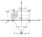
- FIG. 9 is a diagram for explaining the rotational movement of the billboard in detail.
- the screen coordinates of the four vertices P 1 , P 2 , P 3 and P 4 of the billboard in the field of view are (-1, -1), (-1, 1), (1, -1), (1, 1) respectively
- the distance d from the viewpoint to the screen is used as the z coordinate
- the distance d from the viewpoint to the screen is calculated by the following equation from the left and right viewing angles Fov left and Fov right .
- a 2 x Fov left / (Fov left + Fov right )
- b 2 ⁇ Fov right / (Fov left + Fov right )
- d b / tan (Fov right )
- the four vertices P 1 , P 2 , P 3 and P 4 of the billboard are rotated in the three-dimensional space by an angle ⁇ , and the four vertices P 1 ′, P 2 ′, P 3 ′ and P of the billboard after rotation are rotated. Calculate the coordinate value of 4 '. If the attitude of the head mounted display 100 is represented by quaternion (quaternion), the rotation angle is calculated by the difference between the attitude of the head mounted display 100 in the first visual field 600 and the attitude of the head mounted display 100 in the second visual field 610 .
- the attitudes q A and q B of the head mounted display 100 in the first visual field 600 and the second visual field 610 are expressed by the following equations.
- q A (qx A , qy A , qz A , qw A )
- q B (qx B , qy B , qz B , qw B )
- the rotation angle q AB of the head mounted display 100 can be obtained by calculating the difference between the attitudes q A and q B of the head mounted display 100 in the first visual field 600 and the second visual field 610 according to the following equation.
- q AB q A * q B -1
- q B -1 (-qx B, -qy B, -qz B, qw B) Therefore, the rotation angle q AB can be obtained by the following equation.
- the four vertexes P 1 , P 2 , P 3 and P 4 of the billboard are rotated at a rotation angle q AB to obtain coordinate values of P 1 ′, P 2 ′, P 3 ′ and P 4 ′.
- the coordinate values of the four vertices are represented as a four-dimensional vector as follows.
- P 1 (-1, -1, d, 0)
- P 2 (-1, 1, d, 0)
- P 3 (1, -1, d, 0)
- P 4 (1, 1, d, 0)
- the rotation of the point p by the quaternion q is given by q ⁇ 1 * p * q, so the four vertices P 1 ′, P 2 ′, P 3 ′ and P 4 ′ after rotation can be obtained by the following equations.
- n is any one of 1 to 4 in the following equation.
- px and py are screen coordinates, and are given by 1 or -1 as described above.
- pz is the distance d from the viewpoint to the screen.
- the rotation angle q AB (qx AB , qy AB , qz AB , qw AB ) is set.
- FIG. 10 is a diagram for explaining the projection of the billboard onto the screen after rotation.
- the client transmits the current position / attitude information of the head mounted display 100 to the server, and the server draws based on the received position / attitude information, and the position used when drawing with the video stream from the server Send attitude information to the client.
- the client performs reprojection processing on the image drawn by the server in order to fill the difference between the position / attitude information used at the time of drawing and the latest position / attitude information. In this way, it is possible to absorb the time difference from the time when the client requests drawing to the server to the time when the image is displayed, including the communication time.
- communication delay may occur due to network congestion or the like, and an error may occur in which the video stream does not arrive on time. If a data arrival error occurs, the previous decoded image is reused, and reprojection processing is performed on the previous decoded image to match the latest position / attitude of the head mounted display 100 for communication delay. It can deal flexibly.
- Reference Signs List 10 control unit 20 input interface, 30 output interface, 32 display panel, 40 communication control unit, 42 network adapter, 44 antenna, 50 storage unit, 64 attitude sensor, 70 external input / output terminal interface, 72 external memory, 90 HDMI transmission / reception Unit, 100 head mounted display, 200 image correction device, 210 transmission / reception unit, 220 decoding unit, 230 position / posture acquisition unit, 240 error detection unit, 250 image storage unit, 260 correction unit, 270 HDMI transmission / reception unit, 300 interface, 400 Network, 500 image generation device, 510 position / posture acquisition unit, 520 viewpoint / line-of-sight setting unit, 530 rendering unit, 40 image storage unit, 550 encoding unit, 560 reception unit.
- the present invention can be used as a technique for correcting an image.
Landscapes
- Engineering & Computer Science (AREA)
- Physics & Mathematics (AREA)
- General Physics & Mathematics (AREA)
- Theoretical Computer Science (AREA)
- General Engineering & Computer Science (AREA)
- Optics & Photonics (AREA)
- Multimedia (AREA)
- Signal Processing (AREA)
- Human Computer Interaction (AREA)
- Health & Medical Sciences (AREA)
- Social Psychology (AREA)
- General Health & Medical Sciences (AREA)
- Computer Networks & Wireless Communication (AREA)
- Databases & Information Systems (AREA)
- Processing Or Creating Images (AREA)
- Transforming Electric Information Into Light Information (AREA)
- Controls And Circuits For Display Device (AREA)
Abstract
送受信部210は、第1時刻のヘッドマウントディスプレイの位置または姿勢にもとづいて描画された画像を第1時刻の位置または姿勢の情報とともに受信する。補正部260は、画像を表示する際の第2時刻のヘッドマウントディスプレイの位置または姿勢の情報を取得し、第1時刻の位置または姿勢と第2時刻の位置または姿勢の差分に応じて、ヘッドマウントディスプレイのスクリーン座標系の視野を平行移動または回転移動させ、画像を平行移動または回転移動後の視野にテクスチャとして貼り付けることにより、画像を補正する。
Description
この発明は、画像を生成し補正する装置および方法に関する。
ゲーム機に接続されたヘッドマウントディスプレイを頭部に装着して、ヘッドマウントディスプレイに表示された画面を見ながら、コントローラなどを操作してゲームプレイすることが行われている。ヘッドマウントディスプレイを装着すると、ヘッドマウントディスプレイに表示される映像以外はユーザは見ないため、映像世界への没入感が高まり、ゲームのエンタテインメント性を一層高める効果がある。また、ヘッドマウントディスプレイに仮想現実(Virtual Reality)の映像を表示させ、ヘッドマウントディスプレイを装着したユーザが頭部を回転させると、360度見渡せる全周囲の仮想空間が表示されるようにすると、さらに映像への没入感が高まり、ゲームなどのアプリケーションの操作性も向上する。
このようにヘッドマウントディスプレイにヘッドトラッキング機能をもたせて、ユーザの頭部の動きと連動して視点や視線方向を変えて仮想現実の映像を生成した場合、仮想現実の映像の生成から表示までに遅延があるため、映像生成時に前提としたユーザの頭部の向きと、映像をヘッドマウントディスプレイに表示した時点でのユーザの頭部の向きとの間でずれが発生し、ユーザは酔ったような感覚(「VR酔い(Virtual Reality Sickness)」などと呼ばれる)に陥ることがある。
さらに、ヘッドマウントディスプレイに表示される映像がサーバからストリーム配信される場合、通信遅延が加わるため、映像の生成時点と映像の表示時点の時間差が大きくなる。またネットワークの輻輳状態によって遅延の予測が難しく、受信エラーが発生することもある。
本発明はこうした課題に鑑みてなされたものであり、その目的は、画像の生成、配信から表示までの遅延に応じて画像を補正することのできる画像補正技術を提供することにある。
上記課題を解決するために、本発明のある態様の画像補正装置は、第1時刻のヘッドマウントディスプレイの位置または姿勢にもとづいて描画された画像を前記第1時刻の位置または姿勢の情報とともに取得する取得部と、前記画像を表示する際の第2時刻のヘッドマウントディスプレイの位置または姿勢の情報を取得し、前記第1時刻の位置または姿勢と前記第2時刻の位置または姿勢の差分に応じて、ヘッドマウントディスプレイのスクリーン座標系の視野を平行移動または回転移動させ、前記画像を平行移動または回転移動後の視野にテクスチャとして貼り付けることにより、前記画像を補正する補正部とを含む。
本発明の別の態様は、画像補正方法である。この方法は、第1時刻のヘッドマウントディスプレイの位置または姿勢にもとづいて描画された画像を前記第1時刻の位置または姿勢の情報とともに取得する取得ステップと、前記画像を表示する際の第2時刻のヘッドマウントディスプレイの位置または姿勢の情報を取得し、前記第1時刻の位置または姿勢と前記第2時刻の位置または姿勢の差分に応じて、ヘッドマウントディスプレイのスクリーン座標系の視野を平行移動または回転移動させ、前記画像を平行移動または回転移動後の視野にテクスチャとして貼り付けることにより、前記画像を補正する補正ステップとを含む。
なお、以上の構成要素の任意の組合せ、本発明の表現を方法、装置、システム、コンピュータプログラム、データ構造、記録媒体などの間で変換したものもまた、本発明の態様として有効である。
本発明によれば、画像の生成、配信から表示までの遅延に応じて画像を補正することができる。
図1は、ヘッドマウントディスプレイ100の外観図である。ヘッドマウントディスプレイ100は、ユーザの頭部に装着してディスプレイに表示される静止画や動画などを鑑賞し、ヘッドホンから出力される音声や音楽などを聴くための表示装置である。
ヘッドマウントディスプレイ100に内蔵または外付けされたジャイロセンサや加速度センサなどによりヘッドマウントディスプレイ100を装着したユーザの頭部の位置情報と頭部の回転角や傾きなどの姿勢(orientation)情報を計測することができる。
ヘッドマウントディスプレイ100にはカメラユニットが搭載されており、ユーザがヘッドマウントディスプレイ100を装着している間、外界を撮影することができる。
ヘッドマウントディスプレイ100は、「ウェアラブルディスプレイ」の一例である。ここでは、ヘッドマウントディスプレイ100に表示される画像の生成方法を説明するが、本実施の形態の画像生成方法は、狭義のヘッドマウントディスプレイ100に限らず、めがね、めがね型ディスプレイ、めがね型カメラ、ヘッドフォン、ヘッドセット(マイクつきヘッドフォン)、イヤホン、イヤリング、耳かけカメラ、帽子、カメラつき帽子、ヘアバンドなどを装着した場合にも適用することができる。
図2は、本実施の形態に係る画像生成システムの構成図である。ヘッドマウントディスプレイ100は、一例として、映像・音声をデジタル信号で伝送する通信インタフェースの標準規格であるHDMI(登録商標)(High-Definition Multimedia Interface)などのインタフェース300で画像補正装置200に接続される。
画像補正装置200の一例はゲーム機である。画像補正装置200はネットワーク400を介して画像生成装置500に接続される。画像補正装置200はクライアントであり、画像生成装置500はサーバである。画像生成装置500は、複数のユーザがネットワークを介して参加できるゲームなどのオンラインアプリケーションを画像補正装置200に提供してもよい。
画像補正装置200は、ヘッドマウントディスプレイ100の位置・姿勢情報を画像生成装置500に送信する。画像生成装置500は、受信されたヘッドマウントディスプレイ100の位置・姿勢情報にもとづいてヘッドマウントディスプレイ100に表示されるべき画像を描画し、描画データを符号化してビデオストリームとして画像補正装置200に送信する。画像補正装置200は、受信したビデオストリームを復号し、描画データをヘッドマウントディスプレイ100の最新の位置・姿勢に合わせて補正し、ヘッドマウントディスプレイ100に表示する。
図3は、ヘッドマウントディスプレイ100の機能構成図である。
制御部10は、画像信号、センサ信号などの信号や、命令やデータを処理して出力するメインプロセッサである。入力インタフェース20は、ユーザからの操作信号や設定信号を受け付け、制御部10に供給する。出力インタフェース30は、制御部10から画像信号を受け取り、ディスプレイパネル32に表示する。
通信制御部40は、ネットワークアダプタ42またはアンテナ44を介して、有線または無線通信により、制御部10から入力されるデータを外部に送信する。通信制御部40は、また、ネットワークアダプタ42またはアンテナ44を介して、有線または無線通信により、外部からデータを受信し、制御部10に出力する。
記憶部50は、制御部10が処理するデータやパラメータ、操作信号などを一時的に記憶する。
姿勢センサ64は、ヘッドマウントディスプレイ100の位置情報と、ヘッドマウントディスプレイ100の回転角や傾きなどの姿勢情報を検出する。姿勢センサ64は、ジャイロセンサ、加速度センサ、角加速度センサなどを適宜組み合わせて実現される。3軸地磁気センサ、3軸加速度センサおよび3軸ジャイロ(角速度)センサの少なくとも1つ以上を組み合わせたモーションセンサを用いて、ユーザの頭部の前後、左右、上下の動きを検出してもよい。
外部入出力端子インタフェース70は、USB(Universal Serial Bus)コントローラなどの周辺機器を接続するためのインタフェースである。外部メモリ72は、フラッシュメモリなどの外部メモリである。
HDMI送受信部90は、HDMIにしたがって映像・音声のデジタル信号を画像補正装置200との間で送受信する。HDMI送受信部90は、画像補正装置200により生成された画像をHDMI伝送路で画像補正装置200から受信し、制御部10に供給する。
制御部10は、画像やテキストデータを出力インタフェース30に供給してディスプレイパネル32に表示させたり、通信制御部40に供給して外部に送信させることができる。
姿勢センサ64が検出したヘッドマウントディスプレイ100の現在の位置・姿勢情報は、通信制御部40または外部入出力端子インタフェース70を介して画像補正装置200に通知される。あるいは、HDMI送受信部90がヘッドマウントディスプレイ100の現在の位置・姿勢情報を画像補正装置200に送信してもよい。
図4は、本実施の形態に係る画像生成装置500の機能構成図である。同図は機能に着目したブロック図を描いており、これらの機能ブロックはハードウエアのみ、ソフトウエアのみ、またはそれらの組合せによっていろいろな形で実現することができる。
画像生成装置500の少なくとも一部の機能を画像補正装置200に実装してもよい。
送受信部560は、ヘッドマウントディスプレイ100の現在(「第1時刻」と呼ぶ)の位置・姿勢情報を画像補正装置200から受信し、位置・姿勢取得部510に供給する。
視点・視線設定部520は、位置・姿勢取得部510により取得された第1時刻のヘッドマウントディスプレイ100の位置・姿勢情報を用いて、ユーザの視点位置および視線方向を設定する。
レンダリング部530は、視点・視線設定部520によって設定されたユーザの視点位置および視線方向にしたがって、ヘッドマウントディスプレイ100を装着したユーザの視点位置から視線方向に見える仮想空間のオブジェクトをレンダリングし、画像記憶部540に記憶する。
符号化部550は、画像記憶部540に記憶されたレンダリング結果を符号化し、符号化されたビデオストリームを送受信部560に与える。
送受信部560は、レンダリング部530による描画に使用された第1時刻のヘッドマウントディスプレイ100の位置・姿勢情報を位置・姿勢取得部510から受け取り、ビデオストリームデータを第1時刻の位置・姿勢情報とともに画像補正装置200に送信する。これにより、フレーム単位でビデオデータと位置・姿勢情報が関連づけられたビデオストリームがサーバである画像生成装置500からクライアントである画像補正装置200に配信される。
図5は、本実施の形態に係る画像補正装置200の機能構成図である。同図は機能に着目したブロック図を描いており、これらの機能ブロックはハードウエアのみ、ソフトウエアのみ、またはそれらの組合せによっていろいろな形で実現することができる。
画像補正装置200の少なくとも一部の機能をヘッドマウントディスプレイ100の制御部10に実装してもよい。
送受信部210は、ビデオストリームデータと描画に使用された第1時刻のヘッドマウントディスプレイ100の位置・姿勢情報をフレーム単位で画像生成装置500から受信する。送受信部210は、受信したビデオストリームデータを復号部220に与え、第1時刻のヘッドマウントディスプレイ100の位置・姿勢情報を位置・姿勢取得部230に与える。
復号部220は、ビデオストリームデータを復号し、復号画像を第1時刻の位置・姿勢情報とともに画像記憶部250に記憶する。
HDMI送受信部270は、ヘッドマウントディスプレイ100から最新(「第2時刻」と呼ぶ)の位置・姿勢情報を受信し、位置・姿勢取得部230に与える。
位置・姿勢取得部230は、第1時刻の位置・姿勢情報と第2時刻の位置・姿勢情報を補正部260に与える。
補正部260は、画像記憶部250から復号画像を読み出し、第1時刻の位置・姿勢情報と第2時刻の位置・姿勢情報の差分に応じて画像データを補正するリプロジェクション処理を行い、ヘッドマウントディスプレイ100の最新の視点位置・視線方向から見える画像に変換する。補正部260は補正された画像データをHDMI送受信部270に与え、HDMI送受信部270は補正された画像データをヘッドマウントディスプレイ100に送信する。
エラー検出部240は、ネットワークの輻輳などによってビデオストリームデータが遅延し、送受信部210がフレームの描画タイミングにおいて必要なビデオストリームデータを受信できなかった場合をエラーとして検出する。エラー検出部240は、エラー発生を補正部260に通知する。補正部260は、遅延によりエラーが発生した場合、画像記憶部250から一つ前のフレームの復号画像を読み出し、一つ前のフレームの復号画像の描画に使用された過去の時刻の位置・姿勢情報と第2時刻の位置・姿勢情報の差分に応じて一つ前のフレームの復号画像を補正するリプロジェクション処理を行い、ヘッドマウントディスプレイ100の最新の視点位置・視線方向から見える画像に変換する。
ここで、リプロジェクションについて説明する。ヘッドマウントディスプレイ100にヘッドトラッキング機能をもたせて、ユーザの頭部の動きと連動して視点や視線方向を変えて仮想現実の映像を生成した場合、仮想現実の映像の生成から表示までに遅延があるため、映像生成時に前提としたユーザの頭部の向きと、映像をヘッドマウントディスプレイ100に表示した時点でのユーザの頭部の向きとの間でずれが発生し、ユーザは酔ったような感覚(「VR酔い(Virtual Reality Sickness)」などと呼ばれる)に陥ることがある。
このように、ヘッドマウントディスプレイ100の動きを検知し、CPUが描画コマンドを発行し、GPU(Graphics Processing Unit)がレンダリングを実行し、描画された画像がヘッドマウントディスプレイ100に出力されるまでには時間がかかる。描画がたとえば60fps(フレーム/秒)のフレームレートで行われており、ヘッドマウントディスプレイ100の動きを検知してから画像を出力するまでに1フレーム分の遅れが生じるとする。これはフレームレート60fpsのもとでは、16.67ミリ秒ほどであり、人間がずれを感知するには十分な時間である。
さらに、サーバがレンダリングした画像データを符号化してネットワークを介してクライアントに伝送すると、レンダリングに要した時間に通信時間が加わるため、ヘッドマウントディスプレイ100に表示されるまでにさらに遅れが生じる。
そこで、「タイムワープ」または「リプロジェクション」と呼ばれる処理を行い、レンダリングした画像をヘッドマウントディスプレイ100の最新の位置と姿勢に合わせて補正することで人間がずれを感知しにくいようにする。
図6は、本実施の形態の画像生成手順を説明するフローチャートである。
クライアントである画像補正装置200の送受信部210は、ヘッドマウントディスプレイ100の現在の位置・姿勢情報をサーバである画像生成装置500に送信する(S10)。
画像生成装置500において、送受信部560は、画像補正装置200からヘッドマウントディスプレイ100の現在の位置・姿勢情報を受信する(S12)。レンダリング部530は、ヘッドマウントディスプレイ100の現在の位置・姿勢情報にもとづいてヘッドマウントディスプレイ100に表示されるべき画像をレンダリングする(S14)。
符号化部550は、レンダリング結果の画像データを符号化する(S16)。送受信部560は、符号化されたビデオストリームを描画に使用されたヘッドマウントディスプレイ100の位置・姿勢情報とともに画像補正装置200に送信する(S18)。
画像補正装置200において、送受信部210は、画像生成装置500からビデオストリームと描画に使用されたヘッドマウントディスプレイ100の位置・姿勢情報を受信する(S20)。復号部220は、ビデオストリームを復号する(S22)。補正部260は、描画データをヘッドマウントディスプレイ100の最新の位置・姿勢に合わせて補正するリプロジェクション処理を実行する(S24)。HDMI送受信部270は、補正後の画像データをヘッドマウントディスプレイ100に伝送し、ヘッドマウントディスプレイ100に表示させる(S26)。
ステップS10において画像補正装置200がヘッドマウントディスプレイ100の位置・姿勢情報を画像生成装置500に送信してから、ヘッドマウントディスプレイ100に画像が表示されるまでのラウンドトリップタイム(RTT)の遅延が生じる。ステップS24におけるリプロジェクション処理はこの遅延をユーザに感じさせないように画像を補間する。
図7は、本実施の形態の画像生成手順の詳細なタイムチャートである。
時刻T1において、クライアントである画像補正装置200は、ヘッドマウントディスプレイ100の位置・姿勢情報を取得し、サーバである画像生成装置500に送信する。
時刻T2において、画像生成装置500は、受信したヘッドマウントディスプレイ100の位置・姿勢情報に応じてヘッドマウントディスプレイ100に表示すべき画像を描画する。時刻T3において、画像生成装置500は描画された画像を符号化し、符号化されたビデオストリームデータを描画に用いたヘッドマウントディスプレイ100の位置・姿勢情報とともに画像補正装置200に送信する。
時刻T4において、画像補正装置200は受信したビデオストリームを復号する。時刻T5において、画像補正装置200は復号画像にリプロジェクション処理を施す。復号画像は時刻T1のヘッドマウントディスプレイ100の位置・姿勢情報にもとづいて描画されたものである。時刻T5ではヘッドマウントディスプレイ100を装着したユーザは頭部を角度θ1だけ回転させており、差分ΔT=T5-T1の間のヘッドマウントディスプレイ100の位置・姿勢情報の変化に応じて復号画像が補間される。時刻T6において、画像補正装置200はリプロジェクション処理された復号画像をヘッドマウントディスプレイ100に表示させる。
時刻T7において、画像補正装置200は、ヘッドマウントディスプレイ100の位置・姿勢情報を取得し、画像生成装置500に送信する。
時刻T8において、画像生成装置500は、受信したヘッドマウントディスプレイ100の位置・姿勢情報に応じてヘッドマウントディスプレイ100に表示すべき画像を描画する。時刻T9において、画像生成装置500は描画された画像を符号化し、符号化されたビデオストリームデータを描画に用いたヘッドマウントディスプレイ100の位置・姿勢情報とともに画像補正装置200に送信するが、ネットワークの輻輳によって遅延が発生し、次のフレームのタイミングに間に合わない。
時刻T10において、画像補正装置200はデータの受信にエラーが発生したことを検知し、一つ前のフレームである時刻T4における復号画像(「前回の復号画像」と呼ぶ)をメモリから読み出す。時刻T11において、画像補正装置200は前回の復号画像にリプロジェクション処理を施す。前回の復号画像は時刻T1のヘッドマウントディスプレイ100の位置・姿勢情報にもとづいて描画されたものである。時刻T11ではヘッドマウントディスプレイ100を装着したユーザは頭部を角度θ2だけ回転させており、差分ΔT=T11-T1の間のヘッドマウントディスプレイ100の位置・姿勢情報の変化に応じて画像が補間される。時刻T12において、画像補正装置200はリプロジェクション処理された画像をヘッドマウントディスプレイ100に表示させる。
図8~図10を参照して、画像補正装置200の補正部260によるリプロジェクション処理を詳しく説明する。本実施の形態ではサーバが既に描画した画像をクライアントが受信して補間するため、画素単位のリプロジェクションは行わず、ビルボードを回転させて視野移動分を補間する方法を用いる。スクリーン座標の4頂点の座標値を変換することで画像の線形補間を行うため、クライアントのグラフィックス・プロセッシング・ユニット(GPU)の線形補間の機能を用いて簡単に実装することができる。
図8(a)~図8(c)は、ビルボードの回転移動を説明する図である。
図8(a)は、ヘッドマウントディスプレイ100を装着したユーザが正面を見ているときの第1視野600と、ユーザが頭部を角度θだけ右に回転させたときの第2視野610を示す。ユーザが正面を見ている第1時刻においてサーバは第1視野600に画像を描画するが、描画された画像を表示するタイミングは、ユーザが頭部を角度θだけ回転させた第2時刻である。第2時刻では角度θの方向に垂直な面である第2視野610に描画された画像を補正して表示する必要がある。
図8(b)は、図8(a)の視野の角度θの回転移動を補間するために、ビルボードを回転させる方法を示す。正面の第1視野600のビルボードを角度θだけ逆方向に回転させ、第1視野600に描画された画像を回転後のビルボード620にテクスチャとして貼り付ける。これにより、第1視野600に描画された画像が線形補間されて図8(a)の第2視野610に表示されることになる。
図8(c)は、ユーザが頭部を角度θだけ右に回転させたときにヘッドマウントディスプレイ100に表示される補間画像を示す。第1視野600に描画された画像が線形補間されて第2視野610に表示されている。
図8(b)のビルボードの回転移動は、第1視野600の4頂点を3次元に拡張した座標系で角度θだけ逆に回転させることにより行われる。4頂点のx、y座標はスクリーン座標であり、z座標は、回転中心からの距離dであり、距離dは視野角Fovから計算した値を用いる。
なお、ヘッドマウントディスプレイ100を装着したユーザが頭部を平行移動させた場合は、第1視野600のビルボードを逆方向に平行移動させ、第1視野600のテクスチャを貼り付ければよい。
図9は、ビルボードの回転移動を詳細に説明する図である。
視野のビルボードの4頂点P1、P2、P3、P4のスクリーン座標はそれぞれ(-1,-1)、(-1,1)、(1,-1)、(1,1)であり、3次元に拡張した座標系では、視点からスクリーンまでの距離dをz座標に用いて、(-1,-1,d)、(-1,1,d)、(1,-1,d)、(1,1,d)と表される。
ここで、視点からスクリーンまでの距離dは、左右の視野角Fovleft、Fovrightから次式で計算される。
a=2×Fovleft/(Fovleft+Fovright)
b=2×Fovright/(Fovleft+Fovright)
d=b/tan(Fovright)
a=2×Fovleft/(Fovleft+Fovright)
b=2×Fovright/(Fovleft+Fovright)
d=b/tan(Fovright)
ビルボードの4頂点P1、P2、P3、P4を3次元空間において角度θだけ逆に回転させ、回転後のビルボードの4頂点P1’、P2’、P3’、P4’の座標値を計算する。ヘッドマウントディスプレイ100の姿勢をクオータニオン(4元数)で表すなら、回転角は、第1視野600におけるヘッドマウントディスプレイ100の姿勢と第2視野610におけるヘッドマウントディスプレイ100の姿勢の差分により計算される。
クオータニオンを用いたコンピュータグラフィックスに関する3次元回転などの計算方法については「3D-CGプログラマーのためのクォータニオン入門」(工学社、2004年1月)に記載されている。
第1視野600、第2視野610におけるヘッドマウントディスプレイ100の姿勢qA、qBは次式で表される。
qA = (qxA, qyA, qzA, qwA)
qB = (qxB, qyB, qzB, qwB)
qA = (qxA, qyA, qzA, qwA)
qB = (qxB, qyB, qzB, qwB)
ヘッドマウントディスプレイ100の回転角qABは、第1視野600、第2視野610におけるヘッドマウントディスプレイ100の姿勢qA、qBの差を次式で計算することにより求められる。
qAB = qA * qB -1
qAB = qA * qB -1
クオータニオンの逆数qB
-1は
qB -1 = (-qxB, -qyB, -qzB, qwB)
であるから、回転角qABは次式で求められる。
qAB = qA * qB -1
= (qxA, qyA, qzA, qwA) * (-qxB, -qyB, -qzB, qwB)
= ( qwA * qxB + qxA * qwB + qyA * (-qzB) - qzA * (-qyB),
qwA * qyB - qxA * (-qzB) + qyA * qwB + qzA * (-qxB),
qwA * qzB + qxA * (-qyB) - qyA * (-qxB) + qzA * qwB,
qwA * qwB - qxA * (-qxB) - qyA * (-qyB) - qzA * (-qzB))
ビルボードの4頂点P1、P2、P3、P4を回転角qABで回転させてP1’、P2’、P3’、P4’の座標値を求める。4頂点をクオータニオンで回転させるため、4頂点の座標値を以下のように4次元ベクトルで表す。
P1=(-1,-1,d,0)
P2=(-1,1,d,0)
P3=(1,-1,d,0)
P4=(1,1,d,0)
P1=(-1,-1,d,0)
P2=(-1,1,d,0)
P3=(1,-1,d,0)
P4=(1,1,d,0)
点pのクオータニオンqによる回転は、q-1*p*qで与えられるので、回転後の4頂点P1’、P2’、P3’、P4’は次式で求められる。ただし、次式においてnは1から4のいずれかである。px、pyはスクリーン座標であり、上述のように1または-1で与えられる。pzは視点からスクリーンまでの距離dである。また、回転角qAB=(qxAB,qyAB,qzAB,qwAB)とおいた。
Pn' = qAB -1 * Pn * qAB
= (-qxAB, -qyAB, -qzAB, qwAB) * (px, py, pz, 0) * (qxAB, qyAB, qzAB, qwAB)
= ( qwAB * px + (-qyAB) * pz - (-qzAB) * py,
qwAB * py - (-qxAB) * pz + (-qzAB) * px,
qwAB * pz + (-qxAB) * py - (-qyAB) * px,
-(-qxAB) * px - (-qyAB) * py - (-qzAB) * pz) * (qxAB, qyAB, qzAB, qwAB)
= ((qxAB 2-qyAB 2-qzAB 2+qwAB 2)px + 2(qxAB*qyAB+qzAB*qwAB)py + 2(qxAB*qzAB-qyAB*qwAB)pz,
2(qxAB*qyAB-qzAB*qwAB)px - (qxAB 2-qyAB 2+qzAB 2-qwAB 2)py + 2(qyAB*qzAB+qxAB*qwAB)pz,
2(qxAB*qzAB+qyAB*qwAB)px + 2(qyAB*qzAB-qxAB*qwAB)py - (qxAB 2+qyAB 2-qzAB 2-qwAB 2)pz,
-2*qyAB*qzAB*pxAB)
図10は、回転後のビルボードのスクリーンへの投影を説明する図である。
回転後のビルボードの4頂点P1’、P2’、P3’、P4’は3次元空間にあるため、これをスクリーンに再度投影する必要がある。次式のように、視点からスクリーンまでの距離dと回転後のビルボードの奥行きpz’の比を回転後のビルボードの4頂点Pn’の座標値px’、py’に乗算することにより、スクリーン上の4頂点Pn’screenの座標値を求める。ただし、nは1から4のいずれかである。
Pn’screen = (px', py') * d / pz'
= (px' * d / pz', py' * d / pz')
Pn’screen = (px', py') * d / pz'
= (px' * d / pz', py' * d / pz')
以上、本発明の実施の形態を説明した。通常のリプロジェクション処理は描画から表示までの処理時間を埋めるために行われ、画像生成時点の視点位置および視線方向を前提に生成された画像を、画像表示時点の視点位置および視線方向を用いて補正することにより、画像生成時点から画像表示時点までの時間差分を吸収する。それに対して、本実施の形態のようにヘッドマウントディスプレイ100にネットワークを介して画像をストリーミング配信する場合は、通信時間も含めた時間差分を吸収するためにリプロジェクション処理が行われる。
ストリーム配信の場合、クライアントはヘッドマウントディスプレイ100の現在の位置・姿勢情報をサーバに送信し、サーバは受信した位置・姿勢情報にもとづいて描画し、サーバからビデオストリームとともに描画の際に利用した位置・姿勢情報をクライアントに送信する。クライアントは、描画の際に利用した位置・姿勢情報と最新の位置・姿勢情報の差を埋めるために、サーバが描画した画像にリプロジェクション処理を施す。これにより、クライアントがサーバに描画をリクエストした時点から、通信時間も含めて、画像を表示する時点までの時間差分を吸収することができる。
また、ストリーム配信の場合、ネットワークの輻輳などにより通信遅延が発生し、ビデオストリームが時間通りに到着しないエラーが発生しうる。データの到着エラーが発生した場合は、前回の復号画像を再利用し、ヘッドマウントディスプレイ100の最新の位置・姿勢に合うように前回の復号画像に対してリプロジェクション処理を施すことで通信遅延に柔軟に対処できる。
以上、本発明を実施の形態をもとに説明した。実施の形態は例示であり、それらの各構成要素や各処理プロセスの組合せにいろいろな変形例が可能なこと、またそうした変形例も本発明の範囲にあることは当業者に理解されるところである。そのような変形例を説明する。
10 制御部、 20 入力インタフェース、 30 出力インタフェース、 32 ディスプレイパネル、 40 通信制御部、 42 ネットワークアダプタ、 44 アンテナ、 50 記憶部、 64 姿勢センサ、 70 外部入出力端子インタフェース、 72 外部メモリ、 90 HDMI送受信部、 100 ヘッドマウントディスプレイ、 200 画像補正装置、 210 送受信部、 220 復号部、 230 位置・姿勢取得部、 240 エラー検出部、 250 画像記憶部、 260 補正部、 270 HDMI送受信部、 300 インタフェース、 400 ネットワーク、 500 画像生成装置、 510 位置・姿勢取得部、 520 視点・視線設定部、 530 レンダリング部、 540 画像記憶部、 550 符号化部、 560 送受信部。
この発明は、画像を補正する技術に利用できる。
Claims (5)
- 第1時刻のヘッドマウントディスプレイの位置または姿勢にもとづいて描画された画像を前記第1時刻の位置または姿勢の情報とともに取得する取得部と、
前記画像を表示する際の第2時刻のヘッドマウントディスプレイの位置または姿勢の情報を取得し、前記第1時刻の位置または姿勢と前記第2時刻の位置または姿勢の差分に応じて、ヘッドマウントディスプレイのスクリーン座標系の視野を平行移動または回転移動させ、前記画像を平行移動または回転移動後の視野にテクスチャとして貼り付けることにより、前記画像を補正する補正部とを含むことを特徴とする画像補正装置。 - 前記取得部は、前記画像が符号化された符号化ストリームをネットワークを介して受信し、
前記符号化ストリームを復号して復号画像を取得する復号部をさらに含み、
前記補正部は、前記復号画像を平行移動または回転移動後の視野にテクスチャとして貼り付けることにより、前記復号画像を補正することを特徴とする請求項1に記載の画像補正装置。 - 前記復号部により復号された過去の時刻における復号画像を前記過去の時刻のヘッドマウントディスプレイの位置または姿勢の情報とともに保持する記憶部と、
前記符号化ストリームが表示タイミングに間に合って受信されないエラーを検出する検出部とをさらに含み、
前記補正部は、前記エラーが検出された場合、前記過去の時刻の位置または姿勢と前記第2時刻の位置または姿勢の差分に応じて、前記スクリーン座標系の視野を平行移動または回転移動させ、前記過去の時刻における復号画像を平行移動または回転移動後の視野にテクスチャとして貼り付けることにより、前記過去の時刻における復号画像を補正することを特徴とする請求項2に記載の画像補正装置。 - 第1時刻のヘッドマウントディスプレイの位置または姿勢にもとづいて描画された画像を前記第1時刻の位置または姿勢の情報とともに取得する取得ステップと、
前記画像を表示する際の第2時刻のヘッドマウントディスプレイの位置または姿勢の情報を取得し、前記第1時刻の位置または姿勢と前記第2時刻の位置または姿勢の差分に応じて、ヘッドマウントディスプレイのスクリーン座標系の視野を平行移動または回転移動させ、前記画像を平行移動または回転移動後の視野にテクスチャとして貼り付けることにより、前記画像を補正する補正ステップとを含むことを特徴とする画像補正方法。 - 第1時刻のヘッドマウントディスプレイの位置または姿勢にもとづいて描画された画像を前記第1時刻の位置または姿勢の情報とともに取得する取得機能と、
前記画像を表示する際の第2時刻のヘッドマウントディスプレイの位置または姿勢の情報を取得し、前記第1時刻の位置または姿勢と前記第2時刻の位置または姿勢の差分に応じて、ヘッドマウントディスプレイのスクリーン座標系の視野を平行移動または回転移動させ、前記画像を平行移動または回転移動後の視野にテクスチャとして貼り付けることにより、前記画像を補正する補正機能とをコンピュータに実現させることを特徴とするプログラム。
Priority Applications (1)
| Application Number | Priority Date | Filing Date | Title |
|---|---|---|---|
| US16/766,864 US10969591B2 (en) | 2017-12-12 | 2018-12-05 | Image correction apparatus, image correction method and program |
Applications Claiming Priority (2)
| Application Number | Priority Date | Filing Date | Title |
|---|---|---|---|
| JP2017-238042 | 2017-12-12 | ||
| JP2017238042A JP6944863B2 (ja) | 2017-12-12 | 2017-12-12 | 画像補正装置、画像補正方法およびプログラム |
Publications (1)
| Publication Number | Publication Date |
|---|---|
| WO2019116994A1 true WO2019116994A1 (ja) | 2019-06-20 |
Family
ID=66819195
Family Applications (1)
| Application Number | Title | Priority Date | Filing Date |
|---|---|---|---|
| PCT/JP2018/044798 WO2019116994A1 (ja) | 2017-12-12 | 2018-12-05 | 画像補正装置、画像補正方法およびプログラム |
Country Status (3)
| Country | Link |
|---|---|
| US (1) | US10969591B2 (ja) |
| JP (1) | JP6944863B2 (ja) |
| WO (1) | WO2019116994A1 (ja) |
Cited By (1)
| Publication number | Priority date | Publication date | Assignee | Title |
|---|---|---|---|---|
| WO2021199184A1 (ja) * | 2020-03-30 | 2021-10-07 | 株式会社ソニー・インタラクティブエンタテインメント | 画像表示システム、画像処理装置、画像表示方法、およびコンピュータプログラム |
Families Citing this family (9)
| Publication number | Priority date | Publication date | Assignee | Title |
|---|---|---|---|---|
| CN109637406A (zh) * | 2019-01-04 | 2019-04-16 | 京东方科技集团股份有限公司 | 一种显示装置的显示方法、显示装置以及可读存储介质 |
| JP6655751B1 (ja) | 2019-07-25 | 2020-02-26 | エヌ・ティ・ティ・コミュニケーションズ株式会社 | 映像表示制御装置、方法およびプログラム |
| JP7429512B2 (ja) * | 2019-09-30 | 2024-02-08 | 株式会社ソニー・インタラクティブエンタテインメント | 画像処理装置、画像データ転送装置、画像処理方法、および画像データ転送方法 |
| US20210192681A1 (en) * | 2019-12-18 | 2021-06-24 | Ati Technologies Ulc | Frame reprojection for virtual reality and augmented reality |
| JP6801136B1 (ja) | 2020-05-14 | 2020-12-16 | エヌ・ティ・ティ・コミュニケーションズ株式会社 | 遠隔制御システムとその遠隔作業装置、映像処理装置およびプログラム |
| JP6828205B1 (ja) | 2020-05-14 | 2021-02-10 | エヌ・ティ・ティ・コミュニケーションズ株式会社 | 遠隔作業装置とそのプログラム |
| JP6965398B1 (ja) | 2020-05-14 | 2021-11-10 | エヌ・ティ・ティ・コミュニケーションズ株式会社 | 遠隔制御システム、遠隔作業装置、映像処理装置およびプログラム |
| JP2022137945A (ja) * | 2021-03-09 | 2022-09-22 | 株式会社ソニー・インタラクティブエンタテインメント | 画像生成装置、プログラム、画像生成方法および画像表示システム |
| CN115327782B (zh) * | 2022-10-11 | 2023-03-24 | 歌尔股份有限公司 | 显示控制方法、装置、头戴显示设备以及可读存储介质 |
Citations (2)
| Publication number | Priority date | Publication date | Assignee | Title |
|---|---|---|---|---|
| JP2012033038A (ja) * | 2010-07-30 | 2012-02-16 | Fujitsu Ltd | 模擬映像生成装置、方法、プログラム |
| JP2015095045A (ja) * | 2013-11-11 | 2015-05-18 | 株式会社ソニー・コンピュータエンタテインメント | 画像生成装置および画像生成方法 |
Family Cites Families (4)
| Publication number | Priority date | Publication date | Assignee | Title |
|---|---|---|---|---|
| WO2016201423A1 (en) * | 2015-06-12 | 2016-12-15 | Google Inc. | Electronic display stabilization for head mounted display |
| DE102016109153A1 (de) * | 2016-05-18 | 2017-11-23 | Fraunhofer-Gesellschaft zur Förderung der angewandten Forschung e.V. | Verfahren zum einstellen einer blickrichtung in einer darstellung einer virtuellen umgebung |
| CA3049379A1 (en) * | 2017-01-05 | 2018-07-12 | Philipp K. Lang | Improved accuracy of displayed virtual data with optical head mount displays for mixed reality |
| US10684469B2 (en) * | 2018-10-23 | 2020-06-16 | Dell Products L.P. | Detecting and mitigating motion sickness in augmented and virtual reality systems |
-
2017
- 2017-12-12 JP JP2017238042A patent/JP6944863B2/ja active Active
-
2018
- 2018-12-05 WO PCT/JP2018/044798 patent/WO2019116994A1/ja active Application Filing
- 2018-12-05 US US16/766,864 patent/US10969591B2/en active Active
Patent Citations (2)
| Publication number | Priority date | Publication date | Assignee | Title |
|---|---|---|---|---|
| JP2012033038A (ja) * | 2010-07-30 | 2012-02-16 | Fujitsu Ltd | 模擬映像生成装置、方法、プログラム |
| JP2015095045A (ja) * | 2013-11-11 | 2015-05-18 | 株式会社ソニー・コンピュータエンタテインメント | 画像生成装置および画像生成方法 |
Cited By (1)
| Publication number | Priority date | Publication date | Assignee | Title |
|---|---|---|---|---|
| WO2021199184A1 (ja) * | 2020-03-30 | 2021-10-07 | 株式会社ソニー・インタラクティブエンタテインメント | 画像表示システム、画像処理装置、画像表示方法、およびコンピュータプログラム |
Also Published As
| Publication number | Publication date |
|---|---|
| JP6944863B2 (ja) | 2021-10-06 |
| US20200319463A1 (en) | 2020-10-08 |
| US10969591B2 (en) | 2021-04-06 |
| JP2019106628A (ja) | 2019-06-27 |
Similar Documents
| Publication | Publication Date | Title |
|---|---|---|
| WO2019116994A1 (ja) | 画像補正装置、画像補正方法およびプログラム | |
| US11119319B2 (en) | Rendering device, head-mounted display, image transmission method, and image correction method | |
| RU2665872C2 (ru) | Стереопросмотр | |
| TW201946463A (zh) | 藉由所關注區域之制定的異步時間及空間翹曲 | |
| CN112673642A (zh) | 针对拆分xr的跨层流量优化 | |
| WO2014010157A1 (ja) | 画像生成装置および画像生成方法 | |
| US10681276B2 (en) | Virtual reality video processing to compensate for movement of a camera during capture | |
| WO2019082794A1 (ja) | 画像生成装置、画像生成システム、画像生成方法、およびプログラム | |
| JP7157985B2 (ja) | ユーザに再生するためのオーディオ信号をレンダリングするための装置および方法 | |
| WO2016063617A1 (ja) | 画像生成装置、画像抽出装置、画像生成方法、および画像抽出方法 | |
| US11003408B2 (en) | Image generating apparatus and image generating method | |
| WO2019098198A1 (ja) | 画像生成装置、ヘッドマウントディスプレイ、画像生成システム、画像生成方法、およびプログラム | |
| JP2018033107A (ja) | 動画の配信装置及び配信方法 | |
| US11100716B2 (en) | Image generating apparatus and image generation method for augmented reality | |
| WO2021006191A1 (ja) | 画像表示装置、画像表示システムおよび画像表示方法 | |
| KR20200115631A (ko) | 멀티뷰잉 가상 현실 사용자 인터페이스 | |
| JP7377014B2 (ja) | 画像表示装置、画像表示システムおよび画像表示方法 | |
| JP7047085B2 (ja) | 画像生成装置、画像生成方法、およびプログラム | |
| JP7429761B2 (ja) | 画像表示装置、画像表示システムおよび画像表示方法 | |
| KR101773929B1 (ko) | 광 시야각 영상 처리 시스템, 광 시야각 영상의 전송 및 재생 방법, 및 이를 위한 컴퓨터 프로그램 | |
| US20230224431A1 (en) | Techniques for enabling high fidelity magnification of video | |
| KR101947799B1 (ko) | 가상현실 콘텐츠 서비스를 위한 360도 vr 어안 렌더링 방법 | |
| Liu et al. | Cloud mobile display and interaction framework of virtual reality 3D scenes |
Legal Events
| Date | Code | Title | Description |
|---|---|---|---|
| 121 | Ep: the epo has been informed by wipo that ep was designated in this application |
Ref document number: 18888991 Country of ref document: EP Kind code of ref document: A1 |
|
| NENP | Non-entry into the national phase |
Ref country code: DE |
|
| 122 | Ep: pct application non-entry in european phase |
Ref document number: 18888991 Country of ref document: EP Kind code of ref document: A1 |