WO2019116994A1 - 画像補正装置、画像補正方法およびプログラム - Google Patents
画像補正装置、画像補正方法およびプログラム Download PDFInfo
- Publication number
- WO2019116994A1 WO2019116994A1 PCT/JP2018/044798 JP2018044798W WO2019116994A1 WO 2019116994 A1 WO2019116994 A1 WO 2019116994A1 JP 2018044798 W JP2018044798 W JP 2018044798W WO 2019116994 A1 WO2019116994 A1 WO 2019116994A1
- Authority
- WO
- WIPO (PCT)
- Prior art keywords
- image
- time
- mounted display
- head mounted
- attitude
- Prior art date
- Legal status (The legal status is an assumption and is not a legal conclusion. Google has not performed a legal analysis and makes no representation as to the accuracy of the status listed.)
- Ceased
Links
Images


Classifications
-
- G—PHYSICS
- G02—OPTICS
- G02B—OPTICAL ELEMENTS, SYSTEMS OR APPARATUS
- G02B27/00—Optical systems or apparatus not provided for by any of the groups G02B1/00 - G02B26/00, G02B30/00
- G02B27/01—Head-up displays
- G02B27/017—Head mounted
- G02B27/0172—Head mounted characterised by optical features
-
- G—PHYSICS
- G02—OPTICS
- G02B—OPTICAL ELEMENTS, SYSTEMS OR APPARATUS
- G02B27/00—Optical systems or apparatus not provided for by any of the groups G02B1/00 - G02B26/00, G02B30/00
- G02B27/01—Head-up displays
- G02B27/017—Head mounted
-
- G—PHYSICS
- G02—OPTICS
- G02B—OPTICAL ELEMENTS, SYSTEMS OR APPARATUS
- G02B27/00—Optical systems or apparatus not provided for by any of the groups G02B1/00 - G02B26/00, G02B30/00
- G02B27/0093—Optical systems or apparatus not provided for by any of the groups G02B1/00 - G02B26/00, G02B30/00 with means for monitoring data relating to the user, e.g. head-tracking, eye-tracking
-
- G—PHYSICS
- G02—OPTICS
- G02B—OPTICAL ELEMENTS, SYSTEMS OR APPARATUS
- G02B27/00—Optical systems or apparatus not provided for by any of the groups G02B1/00 - G02B26/00, G02B30/00
- G02B27/01—Head-up displays
- G02B27/0179—Display position adjusting means not related to the information to be displayed
-
- G—PHYSICS
- G06—COMPUTING OR CALCULATING; COUNTING
- G06F—ELECTRIC DIGITAL DATA PROCESSING
- G06F3/00—Input arrangements for transferring data to be processed into a form capable of being handled by the computer; Output arrangements for transferring data from processing unit to output unit, e.g. interface arrangements
- G06F3/01—Input arrangements or combined input and output arrangements for interaction between user and computer
- G06F3/011—Arrangements for interaction with the human body, e.g. for user immersion in virtual reality
- G06F3/012—Head tracking input arrangements
-
- G—PHYSICS
- G06—COMPUTING OR CALCULATING; COUNTING
- G06F—ELECTRIC DIGITAL DATA PROCESSING
- G06F3/00—Input arrangements for transferring data to be processed into a form capable of being handled by the computer; Output arrangements for transferring data from processing unit to output unit, e.g. interface arrangements
- G06F3/14—Digital output to display device ; Cooperation and interconnection of the display device with other functional units
- G06F3/147—Digital output to display device ; Cooperation and interconnection of the display device with other functional units using display panels
-
- H—ELECTRICITY
- H04—ELECTRIC COMMUNICATION TECHNIQUE
- H04N—PICTORIAL COMMUNICATION, e.g. TELEVISION
- H04N21/00—Selective content distribution, e.g. interactive television or video on demand [VOD]
- H04N21/40—Client devices specifically adapted for the reception of or interaction with content, e.g. set-top-box [STB]; Operations thereof
- H04N21/43—Processing of content or additional data, e.g. demultiplexing additional data from a digital video stream; Elementary client operations, e.g. monitoring of home network or synchronising decoder's clock; Client middleware
- H04N21/431—Generation of visual interfaces for content selection or interaction; Content or additional data rendering
- H04N21/4318—Generation of visual interfaces for content selection or interaction; Content or additional data rendering by altering the content in the rendering process, e.g. blanking, blurring or masking an image region
-
- H—ELECTRICITY
- H04—ELECTRIC COMMUNICATION TECHNIQUE
- H04N—PICTORIAL COMMUNICATION, e.g. TELEVISION
- H04N21/00—Selective content distribution, e.g. interactive television or video on demand [VOD]
- H04N21/40—Client devices specifically adapted for the reception of or interaction with content, e.g. set-top-box [STB]; Operations thereof
- H04N21/43—Processing of content or additional data, e.g. demultiplexing additional data from a digital video stream; Elementary client operations, e.g. monitoring of home network or synchronising decoder's clock; Client middleware
- H04N21/442—Monitoring of processes or resources, e.g. detecting the failure of a recording device, monitoring the downstream bandwidth, the number of times a movie has been viewed, the storage space available from the internal hard disk
- H04N21/44213—Monitoring of end-user related data
- H04N21/44218—Detecting physical presence or behaviour of the user, e.g. using sensors to detect if the user is leaving the room or changes his face expression during a TV programme
-
- H—ELECTRICITY
- H04—ELECTRIC COMMUNICATION TECHNIQUE
- H04N—PICTORIAL COMMUNICATION, e.g. TELEVISION
- H04N21/00—Selective content distribution, e.g. interactive television or video on demand [VOD]
- H04N21/40—Client devices specifically adapted for the reception of or interaction with content, e.g. set-top-box [STB]; Operations thereof
- H04N21/47—End-user applications
- H04N21/478—Supplemental services, e.g. displaying phone caller identification, shopping application
- H04N21/4781—Games
-
- H—ELECTRICITY
- H04—ELECTRIC COMMUNICATION TECHNIQUE
- H04N—PICTORIAL COMMUNICATION, e.g. TELEVISION
- H04N21/00—Selective content distribution, e.g. interactive television or video on demand [VOD]
- H04N21/80—Generation or processing of content or additional data by content creator independently of the distribution process; Content per se
- H04N21/81—Monomedia components thereof
- H04N21/816—Monomedia components thereof involving special video data, e.g 3D video
-
- G—PHYSICS
- G02—OPTICS
- G02B—OPTICAL ELEMENTS, SYSTEMS OR APPARATUS
- G02B27/00—Optical systems or apparatus not provided for by any of the groups G02B1/00 - G02B26/00, G02B30/00
- G02B27/01—Head-up displays
- G02B27/0101—Head-up displays characterised by optical features
- G02B2027/0138—Head-up displays characterised by optical features comprising image capture systems, e.g. camera
-
- G—PHYSICS
- G02—OPTICS
- G02B—OPTICAL ELEMENTS, SYSTEMS OR APPARATUS
- G02B27/00—Optical systems or apparatus not provided for by any of the groups G02B1/00 - G02B26/00, G02B30/00
- G02B27/01—Head-up displays
- G02B27/0101—Head-up displays characterised by optical features
- G02B2027/014—Head-up displays characterised by optical features comprising information/image processing systems
-
- G—PHYSICS
- G02—OPTICS
- G02B—OPTICAL ELEMENTS, SYSTEMS OR APPARATUS
- G02B27/00—Optical systems or apparatus not provided for by any of the groups G02B1/00 - G02B26/00, G02B30/00
- G02B27/01—Head-up displays
- G02B27/017—Head mounted
- G02B2027/0178—Eyeglass type
-
- G—PHYSICS
- G02—OPTICS
- G02B—OPTICAL ELEMENTS, SYSTEMS OR APPARATUS
- G02B27/00—Optical systems or apparatus not provided for by any of the groups G02B1/00 - G02B26/00, G02B30/00
- G02B27/01—Head-up displays
- G02B27/0179—Display position adjusting means not related to the information to be displayed
- G02B2027/0187—Display position adjusting means not related to the information to be displayed slaved to motion of at least a part of the body of the user, e.g. head, eye
-
- G—PHYSICS
- G09—EDUCATION; CRYPTOGRAPHY; DISPLAY; ADVERTISING; SEALS
- G09G—ARRANGEMENTS OR CIRCUITS FOR CONTROL OF INDICATING DEVICES USING STATIC MEANS TO PRESENT VARIABLE INFORMATION
- G09G2354/00—Aspects of interface with display user
-
- G—PHYSICS
- G09—EDUCATION; CRYPTOGRAPHY; DISPLAY; ADVERTISING; SEALS
- G09G—ARRANGEMENTS OR CIRCUITS FOR CONTROL OF INDICATING DEVICES USING STATIC MEANS TO PRESENT VARIABLE INFORMATION
- G09G2370/00—Aspects of data communication
- G09G2370/02—Networking aspects
- G09G2370/022—Centralised management of display operation, e.g. in a server instead of locally
Definitions
- the present invention relates to an apparatus and method for generating and correcting an image.
- a head mounted display connected to a game machine is mounted on a head, and while watching a screen displayed on the head mounted display, game play is performed by operating a controller or the like.
- the head mounted display is attached, the user can not see anything other than the image displayed on the head mounted display, so the sense of immersion in the image world is enhanced, and the effect of further enhancing the entertainment of the game can be obtained.
- an image of Virtual Reality is displayed on the head mounted display, and a user wearing the head mounted display rotates the head, a virtual space with 360 degree view can be displayed. Immersion to the image is enhanced, and the operability of applications such as games is also improved.
- a head mounted display is provided with a head tracking function
- a virtual reality image is generated by changing the viewpoint and the gaze direction in conjunction with the movement of the head of the user, from generation of a virtual reality image to display Since there is a delay, a gap occurs between the direction of the user's head assumed when generating the image and the direction of the user's head when the image is displayed on the head mounted display, and the user seems drunk May fall into a sense (called "Virtual Reality Sickness" or the like).
- the present invention has been made in view of these problems, and an object thereof is to provide an image correction technique capable of correcting an image according to the delay from generation to distribution and display of the image.
- an image correction apparatus acquires an image drawn based on the position or orientation of a head mounted display at a first time along with information on the position or orientation of the first time Information on the position or attitude of the head mount display at the second time when the image is displayed, and the difference between the position or attitude at the first time and the position or attitude at the second time
- a correction unit that corrects the image by translating or rotating the field of view of the screen coordinate system of the head mounted display and attaching the image as a texture to the field of view after the parallel or rotating movement.
- Another aspect of the present invention is an image correction method.
- This method comprises an acquisition step of acquiring an image drawn based on the position or attitude of the head mounted display at a first time together with information of the position or attitude at the first time, and a second time when the image is displayed Information of the position or attitude of the head mounted display, and translating or changing the field of view of the screen coordinate system of the head mounted display according to the difference between the position or attitude at the first time and the position or attitude at the second time And correcting the image by rotationally moving and pasting the image as a texture to the field of view after parallel movement or rotational movement.
- FIG. 1 is a configuration diagram of an image generation system according to the present embodiment. It is a function block diagram of a head mounted display. It is a functional block diagram of the image generation apparatus concerning this Embodiment. It is a functional block diagram of the image correction apparatus which concerns on this Embodiment. It is a flowchart explaining the image generation procedure of this Embodiment. It is a detailed time chart of an image generation procedure of this embodiment. 8 (a) to 8 (c) are diagrams for explaining the rotational movement of the billboard. It is a figure explaining the rotational movement of a billboard in detail. It is a figure explaining the projection to the screen of the billboard after rotation.
- FIG. 1 is an external view of a head mounted display 100.
- the head mounted display 100 is a display device mounted on the head of the user for viewing still images, moving images, and the like displayed on the display and listening to sounds, music, and the like output from headphones.
- a camera unit is mounted on the head mounted display 100, and while the user is wearing the head mounted display 100, the outside world can be photographed.
- the head mounted display 100 is an example of a “wearable display”.
- a method of generating an image displayed on the head mounted display 100 will be described.
- the method of generating an image according to the present embodiment is not limited to the head mounted display 100 in a narrow sense, but a glasses, glasses type display, glasses type camera, It can also be applied when wearing headphones, headsets (headphones with microphones), earphones, earrings, earpiece cameras, hats, camera hats, hair bands etc.
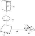
- FIG. 2 is a block diagram of an image generation system according to the present embodiment.
- the head mounted display 100 is connected to the image correction device 200 by an interface 300 such as HDMI (High-Definition Multimedia Interface), which is a standard of a communication interface for transmitting video and audio as digital signals, as an example. .
- HDMI High-Definition Multimedia Interface
- An example of the image correction apparatus 200 is a game machine.
- the image correction device 200 is connected to the image generation device 500 via the network 400.
- the image correction apparatus 200 is a client, and the image generation apparatus 500 is a server.
- the image generation apparatus 500 may provide the image correction apparatus 200 with an online application such as a game in which a plurality of users can participate via a network.
- the image correction device 200 transmits the position / attitude information of the head mounted display 100 to the image generation device 500.
- the image generation apparatus 500 draws an image to be displayed on the head mounted display 100 based on the received position / attitude information of the head mounted display 100, encodes the drawing data, and transmits it to the image correction apparatus 200 as a video stream. Do.
- the image correction apparatus 200 decodes the received video stream, corrects the drawing data in accordance with the latest position and orientation of the head mounted display 100, and displays the corrected data on the head mounted display 100.
- FIG. 3 is a functional block diagram of the head mounted display 100. As shown in FIG.
- the control unit 10 is a main processor that processes and outputs signals such as image signals and sensor signals, and instructions and data.
- the input interface 20 receives an operation signal and a setting signal from the user and supplies the control unit 10 with the operation signal and the setting signal.
- the output interface 30 receives an image signal from the control unit 10 and displays it on the display panel 32.
- the communication control unit 40 transmits data input from the control unit 10 to the outside through wired or wireless communication via the network adapter 42 or the antenna 44.
- the communication control unit 40 also receives data from the outside by wired or wireless communication via the network adapter 42 or the antenna 44, and outputs the data to the control unit 10.
- the storage unit 50 temporarily stores data to be processed by the control unit 10, parameters, operation signals and the like.
- the attitude sensor 64 detects position information of the head mounted display 100 and attitude information such as a rotation angle or tilt of the head mounted display 100.
- the attitude sensor 64 is realized by appropriately combining a gyro sensor, an acceleration sensor, an angular acceleration sensor, and the like.
- a motion sensor combining at least one or more of a three-axis geomagnetic sensor, a three-axis acceleration sensor, and a three-axis gyro (angular velocity) sensor may be used to detect front / rear, left / right, up / down motion of the user's head.
- the external input / output terminal interface 70 is an interface for connecting peripheral devices such as a USB (Universal Serial Bus) controller.
- the external memory 72 is an external memory such as a flash memory.
- the HDMI transmitting and receiving unit 90 transmits and receives digital signals of video and audio to and from the image correction apparatus 200 according to the HDMI.
- the HDMI transmitting and receiving unit 90 receives an image generated by the image correction apparatus 200 from the image correction apparatus 200 through the HDMI transmission path, and supplies the image to the control unit 10.
- the control unit 10 can supply an image or text data to the output interface 30 for display on the display panel 32, or can supply the image or text data to the communication control unit 40 to be transmitted to the outside.
- the current position / attitude information of the head mounted display 100 detected by the attitude sensor 64 is notified to the image correction apparatus 200 via the communication control unit 40 or the external input / output terminal interface 70.
- the HDMI transmitting / receiving unit 90 may transmit the current position / attitude information of the head mounted display 100 to the image correction apparatus 200.
- FIG. 4 is a functional configuration diagram of an image generation apparatus 500 according to the present embodiment.
- the figure depicts a block diagram focusing on functions, and these functional blocks can be realized in various forms by hardware only, software only, or a combination thereof.
- At least a part of the functions of the image generation device 500 may be implemented in the image correction device 200.
- the transmission / reception unit 560 receives the current position (or “first time”) position / attitude information of the head mounted display 100 from the image correction apparatus 200 and supplies the position / attitude acquisition unit 510 with the information.
- the viewpoint and line of sight setting unit 520 sets the viewpoint position and the line of sight direction of the user using the position and orientation information of the head mounted display 100 at the first time acquired by the position and orientation acquisition unit 510.
- the rendering unit 530 renders an object in a virtual space viewed from the viewpoint position of the user wearing the head mounted display 100 according to the viewpoint position and the gaze direction of the user set by the viewpoint / visual axis setting unit 520, It is stored in the storage unit 540.
- the encoding unit 550 encodes the rendering result stored in the image storage unit 540, and supplies the encoded video stream to the transmission / reception unit 560.
- the transmitting / receiving unit 560 receives the position / attitude information of the head mounted display 100 at the first time used for drawing by the rendering unit 530 from the position / attitude acquiring unit 510, and combines the video stream data with the position / attitude information at the first time. It is transmitted to the image correction apparatus 200.
- a video stream in which video data and position / posture information are associated in frame units is distributed from the image generation apparatus 500 as a server to the image correction apparatus 200 as a client.
- FIG. 5 is a functional configuration diagram of the image correction device 200 according to the present embodiment.
- the figure depicts a block diagram focusing on functions, and these functional blocks can be realized in various forms by hardware only, software only, or a combination thereof.
- At least a part of the functions of the image correction apparatus 200 may be implemented in the control unit 10 of the head mounted display 100.
- the transmitting / receiving unit 210 receives the video stream data and the position / attitude information of the head mounted display 100 at the first time used for drawing from the image generation apparatus 500 in frame units.
- the transmitting and receiving unit 210 supplies the received video stream data to the decoding unit 220, and supplies the position and orientation information of the head mounted display 100 at the first time to the position and orientation acquiring unit 230.
- the decoding unit 220 decodes the video stream data, and stores the decoded image in the image storage unit 250 together with the position / attitude information of the first time.
- the HDMI transmitting / receiving unit 270 receives the latest (referred to as “second time”) position / attitude information from the head mounted display 100 and supplies the position / attitude acquiring unit 230 with the position / attitude information.
- the position / posture acquisition unit 230 supplies the position / posture information of the first time and the position / posture information of the second time to the correction unit 260.
- the correction unit 260 reads the decoded image from the image storage unit 250, performs reprojection processing for correcting the image data in accordance with the difference between the position and orientation information at the first time and the position and orientation information at the second time, and mounts the head It is converted into an image viewed from the latest viewpoint position and line of sight of the display 100.
- the correction unit 260 supplies the corrected image data to the HDMI transmitting and receiving unit 270, and the HDMI transmitting and receiving unit 270 transmits the corrected image data to the head mounted display 100.
- the error detection unit 240 detects, as an error, a case where the video stream data is delayed due to congestion of the network or the like, and the transmission / reception unit 210 can not receive the video stream data required at the frame drawing timing.
- the error detection unit 240 notifies the correction unit 260 that an error has occurred.
- the correction unit 260 reads the decoded image of the immediately preceding frame from the image storage unit 250, and the position / attitude of the past time used to draw the decoded image of the immediately preceding frame. Performs reprojection processing that corrects the decoded image of the previous frame according to the difference between the information and the position and orientation information at the second time, and converts it into an image viewed from the latest viewpoint position and line of sight of the head mounted display 100 .
- the movement of the head mounted display 100 is detected, the CPU issues a drawing command, the GPU (Graphics Processing Unit) executes rendering, and the drawn image is output to the head mounted display 100.
- draw is performed at a frame rate of, for example, 60 fps (frames / second), and there is a delay of one frame from detection of movement of the head mounted display 100 to output of an image. This is about 16.67 ms at a frame rate of 60 fps, which is a sufficient time for a human to detect a shift.
- image data rendered by the server is encoded and transmitted to the client via the network, communication time is added to the time required for rendering, which causes a further delay before being displayed on the head mounted display 100.
- time warp or “reprojection” is performed to correct the rendered image in accordance with the latest position and posture of the head mounted display 100 so that it is difficult for a human to detect a deviation.
- FIG. 6 is a flowchart for explaining an image generation procedure of the present embodiment.
- the transmission / reception unit 210 of the image correction apparatus 200 as a client transmits the current position / attitude information of the head mounted display 100 to the image generation apparatus 500 as a server (S10).
- the transmission / reception unit 560 receives the current position / attitude information of the head mounted display 100 from the image correction device 200 (S12).
- the rendering unit 530 renders an image to be displayed on the head mounted display 100 based on the current position / attitude information of the head mounted display 100 (S14).
- the encoding unit 550 encodes the image data of the rendering result (S16).
- the transmission / reception unit 560 transmits the encoded video stream to the image correction apparatus 200 together with the position / attitude information of the head mounted display 100 used for drawing (S18).
- the transmission / reception unit 210 receives, from the image generation apparatus 500, the position / attitude information of the head mounted display 100 used for the video stream and the drawing (S20).
- the decoding unit 220 decodes the video stream (S22).
- the correction unit 260 executes a reprojection process to correct the drawing data in accordance with the latest position and orientation of the head mounted display 100 (S24).
- the HDMI transmitting and receiving unit 270 transmits the image data after correction to the head mounted display 100, and causes the head mounted display 100 to display the image data (S26).
- step S10 After the image correction apparatus 200 transmits the position and orientation information of the head mounted display 100 to the image generating apparatus 500 in step S10, a delay of round trip time (RTT) from when the image is displayed on the head mounted display 100 occurs. .
- RTT round trip time
- the reprojection process in step S24 interpolates the image so that the delay is not felt by the user.
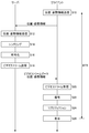
- FIG. 7 is a detailed time chart of the image generation procedure of the present embodiment.
- the image correction apparatus 200 which is a client, acquires the position and orientation information of the head mounted display 100, and transmits the acquired information to the image generation apparatus 500, which is a server.
- the image generation apparatus 500 draws an image to be displayed on the head mounted display 100 according to the received position and orientation information of the head mounted display 100.
- the image generation apparatus 500 encodes the drawn image, and transmits the encoded video stream data to the image correction apparatus 200 together with the position / attitude information of the head mounted display 100 used for drawing.
- the image correction apparatus 200 decodes the received video stream.
- the image correction apparatus 200 performs reprojection processing on the decoded image.
- the decoded image is drawn based on the position / attitude information of the head mounted display 100 at time T1.
- the image correction apparatus 200 causes the head mounted display 100 to display the decoded image subjected to the reprojection processing.
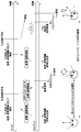
- the image correction apparatus 200 acquires position / posture information of the head mounted display 100, and transmits the acquired information to the image generation apparatus 500.
- the image generation apparatus 500 draws an image to be displayed on the head mounted display 100 according to the received position and orientation information of the head mounted display 100.
- the image generation apparatus 500 encodes the drawn image and transmits the encoded video stream data to the image correction apparatus 200 together with the position / attitude information of the head mounted display 100 used for drawing, but the network Congestion causes a delay and can not be in time for the next frame.
- the image correction apparatus 200 detects that an error has occurred in the reception of data, and reads from the memory a decoded image (referred to as a “previous decoded image”) at time T4, which is the immediately preceding frame.
- the image correction apparatus 200 performs reprojection processing on the previous decoded image.
- the previous decoded image is drawn based on the position / attitude information of the head mounted display 100 at time T1.
- the image correction apparatus 200 causes the head mounted display 100 to display the image subjected to the reprojection processing.
- the reprojection processing by the correction unit 260 of the image correction apparatus 200 will be described in detail with reference to FIGS. 8 to 10.
- the client since the client receives and interpolates the image already drawn by the server, re-projection in units of pixels is not performed, and a method of rotating the billboard to interpolate the movement of the visual field is used. Since linear interpolation of an image is performed by converting coordinate values of four vertices of screen coordinates, it can be easily implemented using the function of linear interpolation of the graphics processing unit (GPU) of the client.
- GPU graphics processing unit
- 8 (a) to 8 (c) are diagrams for explaining the rotational movement of the billboard.
- FIG. 8A shows a first visual field 600 when the user wearing the head mounted display 100 is looking forward and a second visual field 610 when the user rotates the head to the right by an angle ⁇ .
- the server draws an image in the first visual field 600 at a first time when the user is looking forward, but the timing for displaying the drawn image is a second time when the user rotates the head by an angle ⁇ .
- the second time it is necessary to correct and display the image drawn in the second visual field 610 which is a plane perpendicular to the direction of the angle ⁇ .
- FIG. 8 (b) shows a method of rotating the billboard to interpolate the rotational movement of the angle ⁇ of the field of view of FIG. 8 (a).
- the billboard in the front first visual field 600 is rotated in the reverse direction by an angle ⁇ , and the image drawn in the first visual field 600 is pasted as a texture to the billboard 620 after rotation. Thereby, the image drawn in the first visual field 600 is linearly interpolated and displayed in the second visual field 610 of FIG. 8A.
- FIG. 8C shows an interpolated image displayed on the head mounted display 100 when the user rotates the head to the right by the angle ⁇ .
- the image drawn in the first visual field 600 is linearly interpolated and displayed in the second visual field 610.
- the rotational movement of the billboard in FIG. 8B is performed by rotating the four vertexes of the first visual field 600 in a three-dimensionally expanded coordinate system by an angle ⁇ in reverse.
- the x and y coordinates of the four vertices are screen coordinates, the z coordinate is the distance d from the rotation center, and the distance d uses a value calculated from the viewing angle Fov.
- the billboard of the first visual field 600 may be translated in the reverse direction, and the texture of the first visual field 600 may be attached.
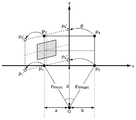
- FIG. 9 is a diagram for explaining the rotational movement of the billboard in detail.
- the screen coordinates of the four vertices P 1 , P 2 , P 3 and P 4 of the billboard in the field of view are (-1, -1), (-1, 1), (1, -1), (1, 1) respectively
- the distance d from the viewpoint to the screen is used as the z coordinate
- the distance d from the viewpoint to the screen is calculated by the following equation from the left and right viewing angles Fov left and Fov right .
- a 2 x Fov left / (Fov left + Fov right )
- b 2 ⁇ Fov right / (Fov left + Fov right )
- d b / tan (Fov right )
- the four vertices P 1 , P 2 , P 3 and P 4 of the billboard are rotated in the three-dimensional space by an angle ⁇ , and the four vertices P 1 ′, P 2 ′, P 3 ′ and P of the billboard after rotation are rotated. Calculate the coordinate value of 4 '. If the attitude of the head mounted display 100 is represented by quaternion (quaternion), the rotation angle is calculated by the difference between the attitude of the head mounted display 100 in the first visual field 600 and the attitude of the head mounted display 100 in the second visual field 610 .
- the attitudes q A and q B of the head mounted display 100 in the first visual field 600 and the second visual field 610 are expressed by the following equations.
- q A (qx A , qy A , qz A , qw A )
- q B (qx B , qy B , qz B , qw B )
- the rotation angle q AB of the head mounted display 100 can be obtained by calculating the difference between the attitudes q A and q B of the head mounted display 100 in the first visual field 600 and the second visual field 610 according to the following equation.
- q AB q A * q B -1
- q B -1 (-qx B, -qy B, -qz B, qw B) Therefore, the rotation angle q AB can be obtained by the following equation.
- the four vertexes P 1 , P 2 , P 3 and P 4 of the billboard are rotated at a rotation angle q AB to obtain coordinate values of P 1 ′, P 2 ′, P 3 ′ and P 4 ′.
- the coordinate values of the four vertices are represented as a four-dimensional vector as follows.
- P 1 (-1, -1, d, 0)
- P 2 (-1, 1, d, 0)
- P 3 (1, -1, d, 0)
- P 4 (1, 1, d, 0)
- the rotation of the point p by the quaternion q is given by q ⁇ 1 * p * q, so the four vertices P 1 ′, P 2 ′, P 3 ′ and P 4 ′ after rotation can be obtained by the following equations.
- n is any one of 1 to 4 in the following equation.
- px and py are screen coordinates, and are given by 1 or -1 as described above.
- pz is the distance d from the viewpoint to the screen.
- the rotation angle q AB (qx AB , qy AB , qz AB , qw AB ) is set.
- FIG. 10 is a diagram for explaining the projection of the billboard onto the screen after rotation.
- the client transmits the current position / attitude information of the head mounted display 100 to the server, and the server draws based on the received position / attitude information, and the position used when drawing with the video stream from the server Send attitude information to the client.
- the client performs reprojection processing on the image drawn by the server in order to fill the difference between the position / attitude information used at the time of drawing and the latest position / attitude information. In this way, it is possible to absorb the time difference from the time when the client requests drawing to the server to the time when the image is displayed, including the communication time.
- communication delay may occur due to network congestion or the like, and an error may occur in which the video stream does not arrive on time. If a data arrival error occurs, the previous decoded image is reused, and reprojection processing is performed on the previous decoded image to match the latest position / attitude of the head mounted display 100 for communication delay. It can deal flexibly.
- Reference Signs List 10 control unit 20 input interface, 30 output interface, 32 display panel, 40 communication control unit, 42 network adapter, 44 antenna, 50 storage unit, 64 attitude sensor, 70 external input / output terminal interface, 72 external memory, 90 HDMI transmission / reception Unit, 100 head mounted display, 200 image correction device, 210 transmission / reception unit, 220 decoding unit, 230 position / posture acquisition unit, 240 error detection unit, 250 image storage unit, 260 correction unit, 270 HDMI transmission / reception unit, 300 interface, 400 Network, 500 image generation device, 510 position / posture acquisition unit, 520 viewpoint / line-of-sight setting unit, 530 rendering unit, 40 image storage unit, 550 encoding unit, 560 reception unit.
- the present invention can be used as a technique for correcting an image.
Landscapes
- Engineering & Computer Science (AREA)
- Physics & Mathematics (AREA)
- General Physics & Mathematics (AREA)
- Theoretical Computer Science (AREA)
- General Engineering & Computer Science (AREA)
- Optics & Photonics (AREA)
- Multimedia (AREA)
- Signal Processing (AREA)
- Human Computer Interaction (AREA)
- Health & Medical Sciences (AREA)
- Social Psychology (AREA)
- General Health & Medical Sciences (AREA)
- Computer Networks & Wireless Communication (AREA)
- Databases & Information Systems (AREA)
- Processing Or Creating Images (AREA)
- Transforming Electric Information Into Light Information (AREA)
- Controls And Circuits For Display Device (AREA)
Priority Applications (1)
| Application Number | Priority Date | Filing Date | Title |
|---|---|---|---|
| US16/766,864 US10969591B2 (en) | 2017-12-12 | 2018-12-05 | Image correction apparatus, image correction method and program |
Applications Claiming Priority (2)
| Application Number | Priority Date | Filing Date | Title |
|---|---|---|---|
| JP2017238042A JP6944863B2 (ja) | 2017-12-12 | 2017-12-12 | 画像補正装置、画像補正方法およびプログラム |
| JP2017-238042 | 2017-12-12 |
Publications (1)
| Publication Number | Publication Date |
|---|---|
| WO2019116994A1 true WO2019116994A1 (ja) | 2019-06-20 |
Family
ID=66819195
Family Applications (1)
| Application Number | Title | Priority Date | Filing Date |
|---|---|---|---|
| PCT/JP2018/044798 Ceased WO2019116994A1 (ja) | 2017-12-12 | 2018-12-05 | 画像補正装置、画像補正方法およびプログラム |
Country Status (3)
| Country | Link |
|---|---|
| US (1) | US10969591B2 (https=) |
| JP (1) | JP6944863B2 (https=) |
| WO (1) | WO2019116994A1 (https=) |
Cited By (2)
| Publication number | Priority date | Publication date | Assignee | Title |
|---|---|---|---|---|
| WO2021199184A1 (ja) * | 2020-03-30 | 2021-10-07 | 株式会社ソニー・インタラクティブエンタテインメント | 画像表示システム、画像処理装置、画像表示方法、およびコンピュータプログラム |
| JP2022158328A (ja) * | 2021-04-01 | 2022-10-17 | 株式会社ソニー・インタラクティブエンタテインメント | 画像生成装置、画像生成方法および画像表示プログラム |
Families Citing this family (21)
| Publication number | Priority date | Publication date | Assignee | Title |
|---|---|---|---|---|
| CN109637406A (zh) * | 2019-01-04 | 2019-04-16 | 京东方科技集团股份有限公司 | 一种显示装置的显示方法、显示装置以及可读存储介质 |
| JP6655751B1 (ja) | 2019-07-25 | 2020-02-26 | エヌ・ティ・ティ・コミュニケーションズ株式会社 | 映像表示制御装置、方法およびプログラム |
| JP7429512B2 (ja) | 2019-09-30 | 2024-02-08 | 株式会社ソニー・インタラクティブエンタテインメント | 画像処理装置、画像データ転送装置、画像処理方法、および画像データ転送方法 |
| JP7389602B2 (ja) | 2019-09-30 | 2023-11-30 | 株式会社ソニー・インタラクティブエンタテインメント | 画像表示システム、画像処理装置、および動画配信方法 |
| JP7498553B2 (ja) | 2019-09-30 | 2024-06-12 | 株式会社ソニー・インタラクティブエンタテインメント | 画像処理装置、画像表示システム、画像データ転送装置、および画像処理方法 |
| JP7491676B2 (ja) | 2019-09-30 | 2024-05-28 | 株式会社ソニー・インタラクティブエンタテインメント | 画像データ転送装置および画像圧縮方法 |
| JP7837134B2 (ja) | 2019-09-30 | 2026-03-30 | 株式会社ソニー・インタラクティブエンタテインメント | 画像データ転送装置および画像圧縮方法 |
| JP7496677B2 (ja) | 2019-09-30 | 2024-06-07 | 株式会社ソニー・インタラクティブエンタテインメント | 画像データ転送装置、画像表示システム、および画像圧縮方法 |
| US12148120B2 (en) * | 2019-12-18 | 2024-11-19 | Ati Technologies Ulc | Frame reprojection for virtual reality and augmented reality |
| JP6965398B1 (ja) | 2020-05-14 | 2021-11-10 | エヌ・ティ・ティ・コミュニケーションズ株式会社 | 遠隔制御システム、遠隔作業装置、映像処理装置およびプログラム |
| JP6828205B1 (ja) | 2020-05-14 | 2021-02-10 | エヌ・ティ・ティ・コミュニケーションズ株式会社 | 遠隔作業装置とそのプログラム |
| JP6801136B1 (ja) | 2020-05-14 | 2020-12-16 | エヌ・ティ・ティ・コミュニケーションズ株式会社 | 遠隔制御システムとその遠隔作業装置、映像処理装置およびプログラム |
| JP7604854B2 (ja) * | 2020-11-30 | 2024-12-24 | セイコーエプソン株式会社 | 虚像表示装置及び虚像表示装置の調整方法 |
| JP7594945B2 (ja) * | 2021-03-09 | 2024-12-05 | 株式会社ソニー・インタラクティブエンタテインメント | 画像生成装置、プログラム、画像生成方法および画像表示システム |
| JP7572066B2 (ja) * | 2022-01-24 | 2024-10-23 | 株式会社分子ロボット総合研究所 | ネットワーク型vrシステム |
| JP7817850B2 (ja) * | 2022-02-10 | 2026-02-19 | 日本放送協会 | メディア処理装置及びユーザ端末 |
| CN115327782B (zh) * | 2022-10-11 | 2023-03-24 | 歌尔股份有限公司 | 显示控制方法、装置、头戴显示设备以及可读存储介质 |
| WO2024086801A2 (en) * | 2022-10-21 | 2024-04-25 | Canon U.S.A., Inc. | System and method for head mount display removal processing |
| US12505522B2 (en) * | 2023-09-18 | 2025-12-23 | Universal City Studios Llc | Image correction system and method |
| CN121844245A (zh) * | 2023-09-18 | 2026-04-10 | 环球城市电影有限责任公司 | 图像校正系统和方法 |
| CN117649818A (zh) * | 2023-12-28 | 2024-03-05 | 厦门天马显示科技有限公司 | 显示面板驱动方法、装置和显示驱动电路芯片 |
Citations (2)
| Publication number | Priority date | Publication date | Assignee | Title |
|---|---|---|---|---|
| JP2012033038A (ja) * | 2010-07-30 | 2012-02-16 | Fujitsu Ltd | 模擬映像生成装置、方法、プログラム |
| JP2015095045A (ja) * | 2013-11-11 | 2015-05-18 | 株式会社ソニー・コンピュータエンタテインメント | 画像生成装置および画像生成方法 |
Family Cites Families (4)
| Publication number | Priority date | Publication date | Assignee | Title |
|---|---|---|---|---|
| KR102292031B1 (ko) * | 2015-06-12 | 2021-08-20 | 구글 엘엘씨 | 헤드 장착 디스플레이를 위한 전자 디스플레이 안정화 |
| DE102016109153A1 (de) * | 2016-05-18 | 2017-11-23 | Fraunhofer-Gesellschaft zur Förderung der angewandten Forschung e.V. | Verfahren zum einstellen einer blickrichtung in einer darstellung einer virtuellen umgebung |
| CA3049379A1 (en) * | 2017-01-05 | 2018-07-12 | Philipp K. Lang | Improved accuracy of displayed virtual data with optical head mount displays for mixed reality |
| US10684469B2 (en) * | 2018-10-23 | 2020-06-16 | Dell Products L.P. | Detecting and mitigating motion sickness in augmented and virtual reality systems |
-
2017
- 2017-12-12 JP JP2017238042A patent/JP6944863B2/ja active Active
-
2018
- 2018-12-05 US US16/766,864 patent/US10969591B2/en active Active
- 2018-12-05 WO PCT/JP2018/044798 patent/WO2019116994A1/ja not_active Ceased
Patent Citations (2)
| Publication number | Priority date | Publication date | Assignee | Title |
|---|---|---|---|---|
| JP2012033038A (ja) * | 2010-07-30 | 2012-02-16 | Fujitsu Ltd | 模擬映像生成装置、方法、プログラム |
| JP2015095045A (ja) * | 2013-11-11 | 2015-05-18 | 株式会社ソニー・コンピュータエンタテインメント | 画像生成装置および画像生成方法 |
Cited By (6)
| Publication number | Priority date | Publication date | Assignee | Title |
|---|---|---|---|---|
| WO2021199184A1 (ja) * | 2020-03-30 | 2021-10-07 | 株式会社ソニー・インタラクティブエンタテインメント | 画像表示システム、画像処理装置、画像表示方法、およびコンピュータプログラム |
| JPWO2021199184A1 (https=) * | 2020-03-30 | 2021-10-07 | ||
| JP7496412B2 (ja) | 2020-03-30 | 2024-06-06 | 株式会社ソニー・インタラクティブエンタテインメント | 画像表示システム、画像処理装置、画像表示方法、およびコンピュータプログラム |
| US12101561B2 (en) | 2020-03-30 | 2024-09-24 | Sony Interactive Entertainment Inc. | Image display system, image processing device, and image display method |
| JP2022158328A (ja) * | 2021-04-01 | 2022-10-17 | 株式会社ソニー・インタラクティブエンタテインメント | 画像生成装置、画像生成方法および画像表示プログラム |
| JP7599370B2 (ja) | 2021-04-01 | 2024-12-13 | 株式会社ソニー・インタラクティブエンタテインメント | 画像生成装置、画像生成方法および画像表示プログラム |
Also Published As
| Publication number | Publication date |
|---|---|
| US20200319463A1 (en) | 2020-10-08 |
| JP2019106628A (ja) | 2019-06-27 |
| US10969591B2 (en) | 2021-04-06 |
| JP6944863B2 (ja) | 2021-10-06 |
Similar Documents
| Publication | Publication Date | Title |
|---|---|---|
| JP6944863B2 (ja) | 画像補正装置、画像補正方法およびプログラム | |
| US11119319B2 (en) | Rendering device, head-mounted display, image transmission method, and image correction method | |
| RU2665872C2 (ru) | Стереопросмотр | |
| JP6978289B2 (ja) | 画像生成装置、ヘッドマウントディスプレイ、画像生成システム、画像生成方法、およびプログラム | |
| JP6711803B2 (ja) | 画像生成装置および画像生成方法 | |
| CN112673642A (zh) | 针对拆分xr的跨层流量优化 | |
| TW201946463A (zh) | 藉由所關注區域之制定的異步時間及空間翹曲 | |
| JP7134060B2 (ja) | 画像生成装置および画像生成方法 | |
| WO2019082794A1 (ja) | 画像生成装置、画像生成システム、画像生成方法、およびプログラム | |
| JP6391423B2 (ja) | 画像生成装置、画像抽出装置、画像生成方法、および画像抽出方法 | |
| US20210058611A1 (en) | Multiviewing virtual reality user interface | |
| JP7429761B2 (ja) | 画像表示装置、画像表示システムおよび画像表示方法 | |
| CN110519247A (zh) | 一种一对多虚拟现实展示方法及装置 | |
| JP2018033107A (ja) | 動画の配信装置及び配信方法 | |
| JP7047085B2 (ja) | 画像生成装置、画像生成方法、およびプログラム | |
| JP7377014B2 (ja) | 画像表示装置、画像表示システムおよび画像表示方法 | |
| CN106445139A (zh) | 一种数据显示方法、装置及系统 | |
| KR101947799B1 (ko) | 가상현실 콘텐츠 서비스를 위한 360도 vr 어안 렌더링 방법 | |
| KR101773929B1 (ko) | 광 시야각 영상 처리 시스템, 광 시야각 영상의 전송 및 재생 방법, 및 이를 위한 컴퓨터 프로그램 | |
| WO2021006191A1 (ja) | 画像表示装置、画像表示システムおよび画像表示方法 | |
| CN121280671A (zh) | 用于控制图像显示的方法、装置、电子设备及存储介质 | |
| Liu et al. | Cloud mobile display and interaction framework of virtual reality 3D scenes |
Legal Events
| Date | Code | Title | Description |
|---|---|---|---|
| 121 | Ep: the epo has been informed by wipo that ep was designated in this application |
Ref document number: 18888991 Country of ref document: EP Kind code of ref document: A1 |
|
| NENP | Non-entry into the national phase |
Ref country code: DE |
|
| 122 | Ep: pct application non-entry in european phase |
Ref document number: 18888991 Country of ref document: EP Kind code of ref document: A1 |