WO2019116454A1 - Dispositif de traitement, procédé de traitement, procédé de marquage, et procédé de fabrication - Google Patents
Dispositif de traitement, procédé de traitement, procédé de marquage, et procédé de fabrication Download PDFInfo
- Publication number
- WO2019116454A1 WO2019116454A1 PCT/JP2017/044623 JP2017044623W WO2019116454A1 WO 2019116454 A1 WO2019116454 A1 WO 2019116454A1 JP 2017044623 W JP2017044623 W JP 2017044623W WO 2019116454 A1 WO2019116454 A1 WO 2019116454A1
- Authority
- WO
- WIPO (PCT)
- Prior art keywords
- area
- modeling
- energy beam
- processing apparatus
- irradiation
- Prior art date
Links
- 238000012545 processing Methods 0.000 title claims abstract description 125
- 238000000034 method Methods 0.000 title claims description 68
- 238000003672 processing method Methods 0.000 title claims description 14
- 238000004519 manufacturing process Methods 0.000 title abstract description 10
- 239000000463 material Substances 0.000 claims abstract description 444
- 230000008859 change Effects 0.000 claims abstract description 45
- 230000001678 irradiating effect Effects 0.000 claims abstract description 31
- 238000012546 transfer Methods 0.000 claims description 154
- 230000033001 locomotion Effects 0.000 claims description 136
- 238000007493 shaping process Methods 0.000 claims description 118
- 239000007789 gas Substances 0.000 claims description 115
- 238000005498 polishing Methods 0.000 claims description 88
- 238000012986 modification Methods 0.000 claims description 34
- 230000004048 modification Effects 0.000 claims description 34
- 238000009792 diffusion process Methods 0.000 claims description 24
- 238000009826 distribution Methods 0.000 claims description 21
- 230000008569 process Effects 0.000 claims description 19
- 239000012778 molding material Substances 0.000 claims description 10
- 239000000843 powder Substances 0.000 claims description 8
- 230000000295 complement effect Effects 0.000 claims description 6
- MYMOFIZGZYHOMD-UHFFFAOYSA-N Dioxygen Chemical compound O=O MYMOFIZGZYHOMD-UHFFFAOYSA-N 0.000 claims description 3
- 239000004566 building material Substances 0.000 claims description 3
- 229910001882 dioxygen Inorganic materials 0.000 claims description 3
- 239000002245 particle Substances 0.000 claims description 3
- 238000007711 solidification Methods 0.000 claims description 2
- 230000008023 solidification Effects 0.000 claims description 2
- 230000004308 accommodation Effects 0.000 claims 4
- QVGXLLKOCUKJST-UHFFFAOYSA-N atomic oxygen Chemical compound [O] QVGXLLKOCUKJST-UHFFFAOYSA-N 0.000 claims 1
- 238000010030 laminating Methods 0.000 claims 1
- 239000001301 oxygen Substances 0.000 claims 1
- 229910052760 oxygen Inorganic materials 0.000 claims 1
- 238000005086 pumping Methods 0.000 claims 1
- 230000005855 radiation Effects 0.000 claims 1
- 230000003287 optical effect Effects 0.000 description 126
- 230000015572 biosynthetic process Effects 0.000 description 93
- 230000001276 controlling effect Effects 0.000 description 81
- 230000007423 decrease Effects 0.000 description 42
- 230000008018 melting Effects 0.000 description 29
- 238000002844 melting Methods 0.000 description 29
- 230000001629 suppression Effects 0.000 description 25
- 230000000875 corresponding effect Effects 0.000 description 21
- 239000011261 inert gas Substances 0.000 description 16
- 101000639461 Rattus norvegicus Small nuclear ribonucleoprotein-associated protein B Proteins 0.000 description 14
- 238000002347 injection Methods 0.000 description 14
- 239000007924 injection Substances 0.000 description 14
- 238000010926 purge Methods 0.000 description 11
- 238000005286 illumination Methods 0.000 description 8
- IJGRMHOSHXDMSA-UHFFFAOYSA-N Atomic nitrogen Chemical compound N#N IJGRMHOSHXDMSA-UHFFFAOYSA-N 0.000 description 7
- 230000000903 blocking effect Effects 0.000 description 7
- 238000003466 welding Methods 0.000 description 7
- XKRFYHLGVUSROY-UHFFFAOYSA-N Argon Chemical compound [Ar] XKRFYHLGVUSROY-UHFFFAOYSA-N 0.000 description 6
- 230000005540 biological transmission Effects 0.000 description 6
- 230000000694 effects Effects 0.000 description 6
- 229910001873 dinitrogen Inorganic materials 0.000 description 5
- 239000006185 dispersion Substances 0.000 description 5
- 238000007517 polishing process Methods 0.000 description 5
- 239000000654 additive Substances 0.000 description 4
- 230000000996 additive effect Effects 0.000 description 4
- 238000000151 deposition Methods 0.000 description 4
- 230000008021 deposition Effects 0.000 description 4
- 238000013461 design Methods 0.000 description 4
- 230000004927 fusion Effects 0.000 description 4
- 238000005259 measurement Methods 0.000 description 4
- 229910052786 argon Inorganic materials 0.000 description 3
- 230000008878 coupling Effects 0.000 description 3
- 238000010168 coupling process Methods 0.000 description 3
- 238000005859 coupling reaction Methods 0.000 description 3
- 238000010586 diagram Methods 0.000 description 3
- 230000001788 irregular Effects 0.000 description 3
- 239000002184 metal Substances 0.000 description 3
- 229910052757 nitrogen Inorganic materials 0.000 description 3
- 230000003746 surface roughness Effects 0.000 description 3
- 101000652736 Homo sapiens Transgelin Proteins 0.000 description 2
- 102100031013 Transgelin Human genes 0.000 description 2
- 238000013459 approach Methods 0.000 description 2
- 239000011230 binding agent Substances 0.000 description 2
- 230000008033 biological extinction Effects 0.000 description 2
- 230000000052 comparative effect Effects 0.000 description 2
- 238000002591 computed tomography Methods 0.000 description 2
- 238000011960 computer-aided design Methods 0.000 description 2
- 239000000470 constituent Substances 0.000 description 2
- 238000005516 engineering process Methods 0.000 description 2
- 239000008187 granular material Substances 0.000 description 2
- 238000003475 lamination Methods 0.000 description 2
- 238000002595 magnetic resonance imaging Methods 0.000 description 2
- 239000000155 melt Substances 0.000 description 2
- 239000007769 metal material Substances 0.000 description 2
- 238000001465 metallisation Methods 0.000 description 2
- 238000000465 moulding Methods 0.000 description 2
- 239000013307 optical fiber Substances 0.000 description 2
- 230000010287 polarization Effects 0.000 description 2
- 230000001902 propagating effect Effects 0.000 description 2
- 239000012260 resinous material Substances 0.000 description 2
- 230000002123 temporal effect Effects 0.000 description 2
- 230000009471 action Effects 0.000 description 1
- 230000001154 acute effect Effects 0.000 description 1
- 230000002238 attenuated effect Effects 0.000 description 1
- 238000005266 casting Methods 0.000 description 1
- 238000007596 consolidation process Methods 0.000 description 1
- 230000002596 correlated effect Effects 0.000 description 1
- 230000003247 decreasing effect Effects 0.000 description 1
- 238000010894 electron beam technology Methods 0.000 description 1
- 239000000835 fiber Substances 0.000 description 1
- 230000005484 gravity Effects 0.000 description 1
- 238000010884 ion-beam technique Methods 0.000 description 1
- 238000004372 laser cladding Methods 0.000 description 1
- 238000001459 lithography Methods 0.000 description 1
- 238000003754 machining Methods 0.000 description 1
- 239000012768 molten material Substances 0.000 description 1
- 238000007500 overflow downdraw method Methods 0.000 description 1
- 239000003973 paint Substances 0.000 description 1
- 239000002994 raw material Substances 0.000 description 1
- 238000011084 recovery Methods 0.000 description 1
- 239000000523 sample Substances 0.000 description 1
- 238000000110 selective laser sintering Methods 0.000 description 1
- 239000004065 semiconductor Substances 0.000 description 1
- 239000007921 spray Substances 0.000 description 1
Images


Classifications
-
- B—PERFORMING OPERATIONS; TRANSPORTING
- B22—CASTING; POWDER METALLURGY
- B22F—WORKING METALLIC POWDER; MANUFACTURE OF ARTICLES FROM METALLIC POWDER; MAKING METALLIC POWDER; APPARATUS OR DEVICES SPECIALLY ADAPTED FOR METALLIC POWDER
- B22F10/00—Additive manufacturing of workpieces or articles from metallic powder
- B22F10/20—Direct sintering or melting
- B22F10/25—Direct deposition of metal particles, e.g. direct metal deposition [DMD] or laser engineered net shaping [LENS]
-
- B—PERFORMING OPERATIONS; TRANSPORTING
- B23—MACHINE TOOLS; METAL-WORKING NOT OTHERWISE PROVIDED FOR
- B23K—SOLDERING OR UNSOLDERING; WELDING; CLADDING OR PLATING BY SOLDERING OR WELDING; CUTTING BY APPLYING HEAT LOCALLY, e.g. FLAME CUTTING; WORKING BY LASER BEAM
- B23K26/00—Working by laser beam, e.g. welding, cutting or boring
- B23K26/34—Laser welding for purposes other than joining
- B23K26/342—Build-up welding
-
- B—PERFORMING OPERATIONS; TRANSPORTING
- B22—CASTING; POWDER METALLURGY
- B22F—WORKING METALLIC POWDER; MANUFACTURE OF ARTICLES FROM METALLIC POWDER; MAKING METALLIC POWDER; APPARATUS OR DEVICES SPECIALLY ADAPTED FOR METALLIC POWDER
- B22F10/00—Additive manufacturing of workpieces or articles from metallic powder
- B22F10/20—Direct sintering or melting
- B22F10/28—Powder bed fusion, e.g. selective laser melting [SLM] or electron beam melting [EBM]
-
- B—PERFORMING OPERATIONS; TRANSPORTING
- B22—CASTING; POWDER METALLURGY
- B22F—WORKING METALLIC POWDER; MANUFACTURE OF ARTICLES FROM METALLIC POWDER; MAKING METALLIC POWDER; APPARATUS OR DEVICES SPECIALLY ADAPTED FOR METALLIC POWDER
- B22F10/00—Additive manufacturing of workpieces or articles from metallic powder
- B22F10/30—Process control
- B22F10/38—Process control to achieve specific product aspects, e.g. surface smoothness, density, porosity or hollow structures
-
- B—PERFORMING OPERATIONS; TRANSPORTING
- B22—CASTING; POWDER METALLURGY
- B22F—WORKING METALLIC POWDER; MANUFACTURE OF ARTICLES FROM METALLIC POWDER; MAKING METALLIC POWDER; APPARATUS OR DEVICES SPECIALLY ADAPTED FOR METALLIC POWDER
- B22F10/00—Additive manufacturing of workpieces or articles from metallic powder
- B22F10/80—Data acquisition or data processing
- B22F10/85—Data acquisition or data processing for controlling or regulating additive manufacturing processes
-
- B—PERFORMING OPERATIONS; TRANSPORTING
- B22—CASTING; POWDER METALLURGY
- B22F—WORKING METALLIC POWDER; MANUFACTURE OF ARTICLES FROM METALLIC POWDER; MAKING METALLIC POWDER; APPARATUS OR DEVICES SPECIALLY ADAPTED FOR METALLIC POWDER
- B22F12/00—Apparatus or devices specially adapted for additive manufacturing; Auxiliary means for additive manufacturing; Combinations of additive manufacturing apparatus or devices with other processing apparatus or devices
- B22F12/22—Driving means
- B22F12/224—Driving means for motion along a direction within the plane of a layer
-
- B—PERFORMING OPERATIONS; TRANSPORTING
- B22—CASTING; POWDER METALLURGY
- B22F—WORKING METALLIC POWDER; MANUFACTURE OF ARTICLES FROM METALLIC POWDER; MAKING METALLIC POWDER; APPARATUS OR DEVICES SPECIALLY ADAPTED FOR METALLIC POWDER
- B22F12/00—Apparatus or devices specially adapted for additive manufacturing; Auxiliary means for additive manufacturing; Combinations of additive manufacturing apparatus or devices with other processing apparatus or devices
- B22F12/22—Driving means
- B22F12/226—Driving means for rotary motion
-
- B—PERFORMING OPERATIONS; TRANSPORTING
- B22—CASTING; POWDER METALLURGY
- B22F—WORKING METALLIC POWDER; MANUFACTURE OF ARTICLES FROM METALLIC POWDER; MAKING METALLIC POWDER; APPARATUS OR DEVICES SPECIALLY ADAPTED FOR METALLIC POWDER
- B22F12/00—Apparatus or devices specially adapted for additive manufacturing; Auxiliary means for additive manufacturing; Combinations of additive manufacturing apparatus or devices with other processing apparatus or devices
- B22F12/40—Radiation means
- B22F12/46—Radiation means with translatory movement
- B22F12/47—Radiation means with translatory movement parallel to the deposition plane
-
- B—PERFORMING OPERATIONS; TRANSPORTING
- B22—CASTING; POWDER METALLURGY
- B22F—WORKING METALLIC POWDER; MANUFACTURE OF ARTICLES FROM METALLIC POWDER; MAKING METALLIC POWDER; APPARATUS OR DEVICES SPECIALLY ADAPTED FOR METALLIC POWDER
- B22F12/00—Apparatus or devices specially adapted for additive manufacturing; Auxiliary means for additive manufacturing; Combinations of additive manufacturing apparatus or devices with other processing apparatus or devices
- B22F12/70—Gas flow means
-
- B—PERFORMING OPERATIONS; TRANSPORTING
- B22—CASTING; POWDER METALLURGY
- B22F—WORKING METALLIC POWDER; MANUFACTURE OF ARTICLES FROM METALLIC POWDER; MAKING METALLIC POWDER; APPARATUS OR DEVICES SPECIALLY ADAPTED FOR METALLIC POWDER
- B22F3/00—Manufacture of workpieces or articles from metallic powder characterised by the manner of compacting or sintering; Apparatus specially adapted therefor ; Presses and furnaces
- B22F3/10—Sintering only
- B22F3/105—Sintering only by using electric current other than for infrared radiant energy, laser radiation or plasma ; by ultrasonic bonding
-
- B—PERFORMING OPERATIONS; TRANSPORTING
- B23—MACHINE TOOLS; METAL-WORKING NOT OTHERWISE PROVIDED FOR
- B23K—SOLDERING OR UNSOLDERING; WELDING; CLADDING OR PLATING BY SOLDERING OR WELDING; CUTTING BY APPLYING HEAT LOCALLY, e.g. FLAME CUTTING; WORKING BY LASER BEAM
- B23K26/00—Working by laser beam, e.g. welding, cutting or boring
- B23K26/02—Positioning or observing the workpiece, e.g. with respect to the point of impact; Aligning, aiming or focusing the laser beam
- B23K26/06—Shaping the laser beam, e.g. by masks or multi-focusing
- B23K26/062—Shaping the laser beam, e.g. by masks or multi-focusing by direct control of the laser beam
- B23K26/0626—Energy control of the laser beam
-
- B—PERFORMING OPERATIONS; TRANSPORTING
- B23—MACHINE TOOLS; METAL-WORKING NOT OTHERWISE PROVIDED FOR
- B23K—SOLDERING OR UNSOLDERING; WELDING; CLADDING OR PLATING BY SOLDERING OR WELDING; CUTTING BY APPLYING HEAT LOCALLY, e.g. FLAME CUTTING; WORKING BY LASER BEAM
- B23K26/00—Working by laser beam, e.g. welding, cutting or boring
- B23K26/08—Devices involving relative movement between laser beam and workpiece
- B23K26/083—Devices involving movement of the workpiece in at least one axial direction
- B23K26/0853—Devices involving movement of the workpiece in at least in two axial directions, e.g. in a plane
-
- B—PERFORMING OPERATIONS; TRANSPORTING
- B23—MACHINE TOOLS; METAL-WORKING NOT OTHERWISE PROVIDED FOR
- B23K—SOLDERING OR UNSOLDERING; WELDING; CLADDING OR PLATING BY SOLDERING OR WELDING; CUTTING BY APPLYING HEAT LOCALLY, e.g. FLAME CUTTING; WORKING BY LASER BEAM
- B23K26/00—Working by laser beam, e.g. welding, cutting or boring
- B23K26/12—Working by laser beam, e.g. welding, cutting or boring in a special atmosphere, e.g. in an enclosure
- B23K26/123—Working by laser beam, e.g. welding, cutting or boring in a special atmosphere, e.g. in an enclosure in an atmosphere of particular gases
-
- B—PERFORMING OPERATIONS; TRANSPORTING
- B23—MACHINE TOOLS; METAL-WORKING NOT OTHERWISE PROVIDED FOR
- B23K—SOLDERING OR UNSOLDERING; WELDING; CLADDING OR PLATING BY SOLDERING OR WELDING; CUTTING BY APPLYING HEAT LOCALLY, e.g. FLAME CUTTING; WORKING BY LASER BEAM
- B23K26/00—Working by laser beam, e.g. welding, cutting or boring
- B23K26/12—Working by laser beam, e.g. welding, cutting or boring in a special atmosphere, e.g. in an enclosure
- B23K26/127—Working by laser beam, e.g. welding, cutting or boring in a special atmosphere, e.g. in an enclosure in an enclosure
-
- B—PERFORMING OPERATIONS; TRANSPORTING
- B23—MACHINE TOOLS; METAL-WORKING NOT OTHERWISE PROVIDED FOR
- B23K—SOLDERING OR UNSOLDERING; WELDING; CLADDING OR PLATING BY SOLDERING OR WELDING; CUTTING BY APPLYING HEAT LOCALLY, e.g. FLAME CUTTING; WORKING BY LASER BEAM
- B23K26/00—Working by laser beam, e.g. welding, cutting or boring
- B23K26/14—Working by laser beam, e.g. welding, cutting or boring using a fluid stream, e.g. a jet of gas, in conjunction with the laser beam; Nozzles therefor
- B23K26/142—Working by laser beam, e.g. welding, cutting or boring using a fluid stream, e.g. a jet of gas, in conjunction with the laser beam; Nozzles therefor for the removal of by-products
-
- B—PERFORMING OPERATIONS; TRANSPORTING
- B23—MACHINE TOOLS; METAL-WORKING NOT OTHERWISE PROVIDED FOR
- B23K—SOLDERING OR UNSOLDERING; WELDING; CLADDING OR PLATING BY SOLDERING OR WELDING; CUTTING BY APPLYING HEAT LOCALLY, e.g. FLAME CUTTING; WORKING BY LASER BEAM
- B23K26/00—Working by laser beam, e.g. welding, cutting or boring
- B23K26/14—Working by laser beam, e.g. welding, cutting or boring using a fluid stream, e.g. a jet of gas, in conjunction with the laser beam; Nozzles therefor
- B23K26/144—Working by laser beam, e.g. welding, cutting or boring using a fluid stream, e.g. a jet of gas, in conjunction with the laser beam; Nozzles therefor the fluid stream containing particles, e.g. powder
-
- B—PERFORMING OPERATIONS; TRANSPORTING
- B23—MACHINE TOOLS; METAL-WORKING NOT OTHERWISE PROVIDED FOR
- B23K—SOLDERING OR UNSOLDERING; WELDING; CLADDING OR PLATING BY SOLDERING OR WELDING; CUTTING BY APPLYING HEAT LOCALLY, e.g. FLAME CUTTING; WORKING BY LASER BEAM
- B23K26/00—Working by laser beam, e.g. welding, cutting or boring
- B23K26/34—Laser welding for purposes other than joining
-
- B—PERFORMING OPERATIONS; TRANSPORTING
- B23—MACHINE TOOLS; METAL-WORKING NOT OTHERWISE PROVIDED FOR
- B23K—SOLDERING OR UNSOLDERING; WELDING; CLADDING OR PLATING BY SOLDERING OR WELDING; CUTTING BY APPLYING HEAT LOCALLY, e.g. FLAME CUTTING; WORKING BY LASER BEAM
- B23K26/00—Working by laser beam, e.g. welding, cutting or boring
- B23K26/70—Auxiliary operations or equipment
- B23K26/702—Auxiliary equipment
-
- B—PERFORMING OPERATIONS; TRANSPORTING
- B29—WORKING OF PLASTICS; WORKING OF SUBSTANCES IN A PLASTIC STATE IN GENERAL
- B29C—SHAPING OR JOINING OF PLASTICS; SHAPING OF MATERIAL IN A PLASTIC STATE, NOT OTHERWISE PROVIDED FOR; AFTER-TREATMENT OF THE SHAPED PRODUCTS, e.g. REPAIRING
- B29C64/00—Additive manufacturing, i.e. manufacturing of three-dimensional [3D] objects by additive deposition, additive agglomeration or additive layering, e.g. by 3D printing, stereolithography or selective laser sintering
- B29C64/30—Auxiliary operations or equipment
- B29C64/386—Data acquisition or data processing for additive manufacturing
- B29C64/393—Data acquisition or data processing for additive manufacturing for controlling or regulating additive manufacturing processes
-
- B—PERFORMING OPERATIONS; TRANSPORTING
- B33—ADDITIVE MANUFACTURING TECHNOLOGY
- B33Y—ADDITIVE MANUFACTURING, i.e. MANUFACTURING OF THREE-DIMENSIONAL [3-D] OBJECTS BY ADDITIVE DEPOSITION, ADDITIVE AGGLOMERATION OR ADDITIVE LAYERING, e.g. BY 3-D PRINTING, STEREOLITHOGRAPHY OR SELECTIVE LASER SINTERING
- B33Y10/00—Processes of additive manufacturing
-
- B—PERFORMING OPERATIONS; TRANSPORTING
- B33—ADDITIVE MANUFACTURING TECHNOLOGY
- B33Y—ADDITIVE MANUFACTURING, i.e. MANUFACTURING OF THREE-DIMENSIONAL [3-D] OBJECTS BY ADDITIVE DEPOSITION, ADDITIVE AGGLOMERATION OR ADDITIVE LAYERING, e.g. BY 3-D PRINTING, STEREOLITHOGRAPHY OR SELECTIVE LASER SINTERING
- B33Y30/00—Apparatus for additive manufacturing; Details thereof or accessories therefor
-
- B—PERFORMING OPERATIONS; TRANSPORTING
- B33—ADDITIVE MANUFACTURING TECHNOLOGY
- B33Y—ADDITIVE MANUFACTURING, i.e. MANUFACTURING OF THREE-DIMENSIONAL [3-D] OBJECTS BY ADDITIVE DEPOSITION, ADDITIVE AGGLOMERATION OR ADDITIVE LAYERING, e.g. BY 3-D PRINTING, STEREOLITHOGRAPHY OR SELECTIVE LASER SINTERING
- B33Y40/00—Auxiliary operations or equipment, e.g. for material handling
-
- B—PERFORMING OPERATIONS; TRANSPORTING
- B33—ADDITIVE MANUFACTURING TECHNOLOGY
- B33Y—ADDITIVE MANUFACTURING, i.e. MANUFACTURING OF THREE-DIMENSIONAL [3-D] OBJECTS BY ADDITIVE DEPOSITION, ADDITIVE AGGLOMERATION OR ADDITIVE LAYERING, e.g. BY 3-D PRINTING, STEREOLITHOGRAPHY OR SELECTIVE LASER SINTERING
- B33Y50/00—Data acquisition or data processing for additive manufacturing
- B33Y50/02—Data acquisition or data processing for additive manufacturing for controlling or regulating additive manufacturing processes
-
- B—PERFORMING OPERATIONS; TRANSPORTING
- B22—CASTING; POWDER METALLURGY
- B22F—WORKING METALLIC POWDER; MANUFACTURE OF ARTICLES FROM METALLIC POWDER; MAKING METALLIC POWDER; APPARATUS OR DEVICES SPECIALLY ADAPTED FOR METALLIC POWDER
- B22F10/00—Additive manufacturing of workpieces or articles from metallic powder
- B22F10/20—Direct sintering or melting
-
- B—PERFORMING OPERATIONS; TRANSPORTING
- B29—WORKING OF PLASTICS; WORKING OF SUBSTANCES IN A PLASTIC STATE IN GENERAL
- B29C—SHAPING OR JOINING OF PLASTICS; SHAPING OF MATERIAL IN A PLASTIC STATE, NOT OTHERWISE PROVIDED FOR; AFTER-TREATMENT OF THE SHAPED PRODUCTS, e.g. REPAIRING
- B29C64/00—Additive manufacturing, i.e. manufacturing of three-dimensional [3D] objects by additive deposition, additive agglomeration or additive layering, e.g. by 3D printing, stereolithography or selective laser sintering
- B29C64/10—Processes of additive manufacturing
- B29C64/141—Processes of additive manufacturing using only solid materials
- B29C64/153—Processes of additive manufacturing using only solid materials using layers of powder being selectively joined, e.g. by selective laser sintering or melting
-
- B—PERFORMING OPERATIONS; TRANSPORTING
- B29—WORKING OF PLASTICS; WORKING OF SUBSTANCES IN A PLASTIC STATE IN GENERAL
- B29C—SHAPING OR JOINING OF PLASTICS; SHAPING OF MATERIAL IN A PLASTIC STATE, NOT OTHERWISE PROVIDED FOR; AFTER-TREATMENT OF THE SHAPED PRODUCTS, e.g. REPAIRING
- B29C64/00—Additive manufacturing, i.e. manufacturing of three-dimensional [3D] objects by additive deposition, additive agglomeration or additive layering, e.g. by 3D printing, stereolithography or selective laser sintering
- B29C64/10—Processes of additive manufacturing
- B29C64/165—Processes of additive manufacturing using a combination of solid and fluid materials, e.g. a powder selectively bound by a liquid binder, catalyst, inhibitor or energy absorber
-
- Y—GENERAL TAGGING OF NEW TECHNOLOGICAL DEVELOPMENTS; GENERAL TAGGING OF CROSS-SECTIONAL TECHNOLOGIES SPANNING OVER SEVERAL SECTIONS OF THE IPC; TECHNICAL SUBJECTS COVERED BY FORMER USPC CROSS-REFERENCE ART COLLECTIONS [XRACs] AND DIGESTS
- Y02—TECHNOLOGIES OR APPLICATIONS FOR MITIGATION OR ADAPTATION AGAINST CLIMATE CHANGE
- Y02P—CLIMATE CHANGE MITIGATION TECHNOLOGIES IN THE PRODUCTION OR PROCESSING OF GOODS
- Y02P10/00—Technologies related to metal processing
- Y02P10/25—Process efficiency
Definitions
- the present invention relates to, for example, a processing apparatus that performs processing for irradiating an object with an energy beam, a processing method, a marking method, and a forming method.
- Patent Document 1 describes a shaping apparatus that forms a shaped object by melting powdery material with an energy beam and then resolidifying the molten material. In such a modeling apparatus, it becomes a technical subject to form an appropriate modeling thing.
- a modeling apparatus including: an energy beam irradiation unit that irradiates a surface of an object with an energy beam to form a molten pool on the surface; and a material supply unit that supplies a modeling material to the molten pool
- a change device for changing the positional relationship between the object and the molten pool, and supplying the modeling material to the molten pool while changing the positional relationship between the object and the molten pool in the first direction
- a processing device is provided that changes the size in a second direction intersecting the first direction of a shaped object formed along the first direction based on the position of the shaped object in the first direction.
- an energy beam irradiation unit for irradiating the surface of an object with an energy beam to form a molten pool on the surface, and a material for supplying a forming material to the molten pool for melting the modeling material
- a forming apparatus having a supply unit, a changing apparatus for changing the position of at least one of the object and the molten pool, and a convex formed on the surface of the object by solidifying the melted forming material
- a control device that controls the change device using coordinate data on the mark such that the three-dimensional object is a mark.
- a modeling apparatus comprising: an energy beam irradiation unit for irradiating the surface of an object with an energy beam to form a molten pool on the surface; and a material supply unit for supplying a modeling material to the molten pool
- a change device for changing the positional relationship between the object and the molten pool, a gas supply device for supplying a specific gas around the molten pool, and a color tone of a shaped object formed by the modeling device
- a control device for controlling the gas supply device so as to change the characteristics of the specific gas supplied to the surroundings.
- an energy beam irradiation unit that irradiates the surface of an object with an energy beam to form a first molten pool on the surface, and a material supply unit that supplies a modeling material to the first molten pool And a changing device for changing the positional relationship between the object and the first molten pool, and changing the positional relationship between the object and the first molten pool in the first direction to the molten pool
- An energy beam is irradiated from the energy beam irradiation unit to the first modeling object formed by supplying the modeling material to form a second molten pool on the first modeling object, and the formation is performed from the material supply unit
- a processing apparatus supplies a material to form a second object, and the second direction size of the second object intersects the first direction is different from the second direction size of the first object.
- an energy beam irradiation unit that irradiates an energy beam to a first region on an object, and a material supply unit that supplies a modeling material to a second region that at least partially overlaps the first region.
- a forming apparatus for forming a shaped object on the object, a position changing apparatus for changing the positions of the first and second areas on the object, and the direction from the material supply unit to the second area There is provided a processing apparatus including a supply amount changing device which changes a supply amount of a modeling material per unit time.
- a modeling apparatus including: an energy beam irradiation unit that irradiates an energy beam to an irradiation area on an object; and a material supply unit that supplies a modeling material to the irradiation area; And changing the positional relationship between the object and the irradiation area in a direction along the surface of the object while supplying the modeling material to the irradiation area.
- Different processing devices are provided at a first position in a direction along the surface of the three-dimensional object and a second position different from the first position in a direction in which the three-dimensional object crosses the direction along the surface of the three-dimensional object Ru.
- the surface of the object is irradiated with an energy beam to form a molten pool on the surface
- the forming material is supplied to the molten pool
- the position of the object and the molten pool Changing the positional relationship between the object and the molten pool in the first direction, including changing the relationship, and supplying the forming material to the molten pool while changing the positional relationship between the object and the molten pool
- a processing method is provided which changes the size of a second direction intersecting the first direction of an object based on the position of the shaped object in the first direction.
- preparing coordinate data regarding a mark to be formed on the surface of an object irradiating an energy beam on the surface of the object to form a molten pool on the surface, and forming the shape Changing the position of at least one of supplying a forming material to the molten pool to melt the material, and changing the position of at least one of the object and the molten pool;
- a processing method of changing the position of the at least one using the coordinate data such that a convex shaped object generated on the surface of the object by the solidification of the melted modeling material becomes the mark. Be done.
- the surface of an object is irradiated with an energy beam to form a molten pool on the surface, the forming material is supplied to the molten pool, and the position of the object and the molten pool
- the forming material is supplied to the molten pool, and the position of the object and the molten pool
- a processing method is provided that includes changing.
- the surface of an object is irradiated with an energy beam to form a first molten pool on the surface
- the forming material is supplied to the first molten pool, the object and the first
- An energy beam is irradiated from the energy beam irradiation unit to the shaped object to form a second molten pool on the first shaped object, and a modeling material is supplied to the second molten pool to form a second shaped object
- the size of a second direction of the second shaped article intersecting the first direction is different from the size of the first shaped article in the second direction.
- the method includes irradiating a first area on an object with an energy beam, and supplying a modeling material to a second area that at least partially overlaps the first area. Forming a three-dimensional object, changing the positions of the first and second regions on the object, and changing the supply amount of the forming material per unit time toward the second region. Methods of treatment are provided.
- the present invention relates to irradiating an irradiation area on an object with an energy beam, supplying a modeling material to the irradiation area, and changing the positional relationship between the object and the irradiation area.
- a direction along the surface of a shaped object formed by supplying the modeling material to the irradiation area while changing the positional relationship between the object and the irradiation area along the surface of the object;
- the size in the intersecting direction is provided with different processing methods at a first position in a direction along the surface of the shaped article and at a second position different from the first position.
- FIG. 1 is a cross-sectional view showing the structure of the modeling system of the present embodiment.
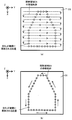
- FIG.2 (a) to FIG.2 (c) is sectional drawing which shows a mode when light is irradiated in the one area
- FIG.3 (a) and FIG.3 (b) is a top view which shows the movement trace of the irradiation area
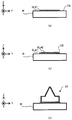
- FIG. 4A to FIG. 4C is a cross-sectional view showing a process of forming a three-dimensional structure.
- FIG.5 (a) is a top view which shows the movement path of the irradiation area
- FIG.5 (b) is a movement of the modeling thing and irradiation area
- FIG. 5C is a cross-sectional view showing a shaped object formed in a region where the paths do not intersect
- FIG. 5C is a region where the movement paths of the shaped region and the irradiated region do not intersect. It is a top view showing the modeling thing formed in.
- FIG.6 (a) to FIG.6 (c) is a graph which shows the supply rate of the modeling material controlled so that dispersion
- FIG. 7 is a graph showing the relationship between the supply rate of the forming material and the supply amount of the forming material from the material nozzle.
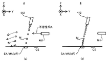
- FIG. 8 (a) is a cross-sectional view showing a supply mode of the modeling material when the gas injection device is injecting the inert gas
- FIG. 8 (b) is a gas injection device injecting the inert gas. It is sectional drawing which shows the supply aspect of the modeling material in not being.
- FIG.9 (a) is sectional drawing which shows the supply aspect of a modeling material in case a shielding member exists in a non-shielding state
- FIG.9 (b) is a supply aspect of a modeling material when a shielding member is in a shielding state It is sectional drawing which shows.
- Fig.10 (a) is sectional drawing which shows the supply aspect of a modeling material when a material nozzle is in a supply state
- FIG.10 (b) is a supply aspect of a modeling material when a material nozzle is in a non-supplying state It is sectional drawing which shows.
- Each of Drawing 11 (a) to Drawing 11 (c) is a graph showing a heat transfer rate controlled so that dispersion of height of a modeling thing may be controlled.
- FIG. 12 is a graph showing the relationship between the heat transfer rate and the light intensity on the irradiation area.
- FIG. 13 (a) is a cross-sectional view showing the irradiation mode of light when the light shielding member is in the light shielding state, and FIG. 13 (b) shows the irradiation mode of light when the light shielding member is in the light non-shielding state.
- FIG. FIG. 14 (a) is a cross-sectional view showing an irradiation mode of light when the focus position is set on the modeling surface, and FIG. 14 (b) is set to a position where the focusing position is away from the modeling surface It is sectional drawing which shows the irradiation aspect of the light in the case of.
- FIG. 15 (a) and FIG.15 (b) is a graph which shows the movement speed of the irradiation area
- Fig.16 (a) is a top view which shows the movement path of the irradiation area
- FIG.16 (b) is a graph which shows the relationship between the movement speed of irradiation area
- FIG. 17 is a graph showing the supply rate of the modeling material controlled based on the moving speed of the irradiation area so as to suppress the variation in the height of the modeling object.
- FIG.16 (a) is a top view which shows the movement path of the irradiation area
- FIG.16 (b) is a graph which shows the relationship between the movement speed of irradiation area
- FIG. 17 is a graph
- FIG. 18 is a graph showing the relationship between the moving speed of the irradiation area, the supply rate of the forming material, and the height of the formed object.
- FIG. 19 is a graph showing a heat transfer rate controlled based on the moving speed of the irradiation area so as to suppress the variation in the height of the shaped object.
- FIG. 20 is a graph showing the relationship between the moving speed of the irradiation area, the heat transfer rate, and the height of the object.
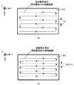
- FIG. 21 (a) is a perspective view showing an example of the position in the existing structure where heat is relatively difficult to be diffused and the position of the region where heat is relatively easily diffused, and FIG.
- FIG. 21 (b) is a heat It is sectional drawing which shows the modeling object formed in the area
- FIG. 22 is a graph showing the supply rate of the modeling material controlled based on the degree of heat diffusion so as to suppress the variation in the height of the modeling object.
- FIG. 23 is a graph showing a heat transfer rate controlled based on the degree of heat diffusion so as to suppress variations in the height of a shaped object.
- FIG. 24 is a graph showing the moving speed of the irradiation area controlled based on the degree of heat diffusion so as to suppress the variation in the height of the shaped object.
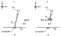
- FIG. 25 (a) is a perspective view showing an example of the position of the region where the light EL is irradiated relatively frequently and the position of the region where the light EL is irradiated relatively less frequently
- FIG. 25 (b) These are sectional drawings which show the three-dimensional object formed in the area
- FIG. 26 is a graph showing the supply rate of the modeling material controlled based on the frequency of light irradiation so as to suppress the variation in the height of the modeling object.
- FIG. 27 is a graph showing a heat transfer rate controlled based on the frequency of light irradiation so as to suppress variations in the height of a shaped object.
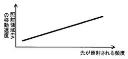
- FIG. 28 is a graph showing the moving speed of the irradiation area controlled based on the frequency of light irradiation so as to suppress the variation in the height of the shaped object.
- FIG. 29 is a plan view and a sectional view showing a mark formed on a formed surface.
- FIG. 30 (a) and FIG.30 (b) is a top view which shows the movement trace of the irradiation area
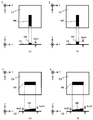
- FIGS. 31A to 31D is a plan view showing a mark whose size is controlled by the size control operation.
- FIG. 32 is a graph showing the relationship between the heat transfer rate and the size of the mark.
- FIG. 33 is a graph showing the relationship between the moving speed of the irradiation area and the size of the mark.
- FIG. 34 is a graph showing the relationship between the size of the irradiation area and the size of the mark.
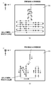
- FIGS. 35 (a) and 35 (b) is a plan view showing the relationship between the size of the mark and the number of linear structures constituting the mark, and FIGS. 35 (c) to 35 (d).
- Each of is a top view which shows the relationship between the size of a mark, and the length of the linear structure which comprises a mark.
- FIG. 36D is a plan view showing a mark whose height is controlled by the height control operation.
- FIG. 37 is a graph showing the relationship between the supply rate and the height of the mark.
- FIG. 38 is a graph showing the relationship between the heat transfer rate and the height of the mark.
- FIG. 39 is a graph showing the relationship between the moving speed of the irradiation area and the height of the mark.
- FIG. 40 (a) and FIG. 40 (b) is a cross-sectional view showing the relationship between the height of the mark and the number of structural layers constituting the mark.
- FIGS. 41 (a) to 41 (c) is a cross-sectional view showing a mark whose surface shape is controlled by the shape control operation.
- FIG. 42 (c) is a cross-sectional view showing a mark whose shape of the connecting surface is controlled by the shape control operation.
- FIG. 43 (a) is a plan view and a cross-sectional view showing a mark pressed against an object as a seal
- FIG. 43 (b) is a plan view showing a seal imprint transferred onto the object against which the mark is pressed.
- FIG. 44 (a) to FIG. 44 (c) is a cross-sectional view showing a mark in which the shape of the connecting surface is controlled to be in a complementary relationship with the target surface of the object.
- FIG. 45 (a) is a graph showing an example of the control mode of the characteristic of the specific gas in the period in which a plurality of marks are formed
- FIG. 45 (a) is a graph showing an example of the control mode of the characteristic of the specific gas in the period in which a plurality of marks are formed
- FIG. 45 (a) is a graph showing an example of the control mode of the characteristic of the specific gas
- FIG. 45 (b) is specified in the control mode shown in FIG. 45 (a)
- FIG. 45 (c) is a plan view showing a plurality of marks formed when the characteristics of the gas are controlled
- FIG. 45 (c) shows an example of a control aspect of the characteristics of the specific gas in a period during which a single mark is formed.
- FIG. 45 (d) is a graph shown
- FIG. 45 (d) is a plan view showing a mark formed when the characteristics of the specific gas are controlled in the control mode shown in FIG. 45 (c).
- Each of FIGS. 46 (a) to 46 (c) is a cross-sectional view showing the state of the surface to be polished during the polishing operation.
- FIG. 47 (a) is a plan view showing the movement path of the irradiation area during the period in which the shaping operation is being performed, and FIG. 47 (b) is the movement of the irradiation area during the period during which the polishing operation is being performed It is a top view which shows a course.
- FIG. 48 (a) is a plan view showing the moving path of the irradiation area during the period in which the shaping operation is being performed, and FIG. 48 (b) is the movement of the irradiation area during the period during which the polishing operation is being performed. It is a top view which shows a course.
- FIG. 49 is a cross-sectional view showing the depth of focus of the illumination optical system provided in the modeling system of the first modification.
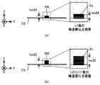
- FIG. 50 (a) is a cross-sectional view showing a structural layer formed by the modeling system of the first modification when the irradiation area is set in a certain area portion on the modeling surface
- FIG. It is sectional drawing which shows the structural layer formed by the modeling system of a 1st modification, when an irradiation area
- FIG. 51 (a) and FIG. 51 (b) is a cross-sectional view showing the positional relationship between the shaped surface and the range of the focal depth of the illumination optical system.
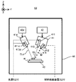
- FIG. 52 is a cross-sectional view showing a structure of a modeling system of a second modified example.
- FIG. 53 (a) is a cross-sectional view showing the structure of the irradiation optical system provided in the modeling system of the third modification
- FIG. 53 (b) shows the structure of the optical system provided in the irradiation optical system of the third modification. It is a perspective view shown.
- FIG. 54 is a cross-sectional view showing the structure of the modeling apparatus provided in the modeling system of the fourth modification.
- FIG. 55 is a cross-sectional view showing the structure of the modeling apparatus provided in the modeling system of the fifth modification.
- FIG. 56 is a cross-sectional view showing a configuration of a formed object formed by the sixth modification.
- FIG. 57 is a cross-sectional view showing a configuration of a formed object formed by the seventh modification.
- FIG. 58 is a cross sectional view showing an operation of the eighth modified example.
- FIG. 59 is a cross-sectional view showing an example of a supply amount changing device used in the eighth modification.
- FIG. 60 is a cross-sectional view showing an example of a supply amount changing device used in the eighth modification.
- FIG. 61 (a) is a plan view showing the movement locus of the irradiation area on the modeling surface, and FIG. 61 (b) is the case where the irradiation area moves along the movement locus shown in FIG. 61 (a) It is sectional drawing which shows a part of molded article formed.
- FIG. 62 (a) is a plan view showing the movement locus of the irradiation area on the formed surface, and FIG. 62 (b) is a case where the irradiation area moves along the movement locus shown in FIG. 62 (a) It is sectional drawing which shows a part of molded article formed.
- LMD Laser Metal Deposition
- Laser build-up welding includes direct metal deposition, direct energy deposition, laser cladding, laser engineered net shaping, direct light fabrication, and laser consolidation. Shape deposition manufacturing, wire-feed laser deposition, gas through wire, laser powder fusion, laser metal forming, selective laser powder remelting, laser direct It may be referred to as casting, laser powder deposition, laser additive manufacturing, laser rapid forming.
- each of the X-axis direction and the Y-axis direction is a horizontal direction (that is, a predetermined direction in a horizontal plane), and the Z-axis direction is a vertical direction (that is, a direction orthogonal to the horizontal plane). In the vertical direction).
- the rotational directions (in other words, the inclined directions) around the X axis, the Y axis and the Z axis will be referred to as the ⁇ X direction, the ⁇ Y direction and the ⁇ Z direction, respectively.
- the Z-axis direction may be the gravity direction.
- the XY plane may be in the horizontal direction.
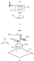
- FIG. 1 is a cross-sectional view showing an example of the structure of a modeling system 1 of the present embodiment.
- the modeling system 1 can form a three-dimensional structure ST (that is, a three-dimensional object having a size in any direction of three-dimensional directions, and a three-dimensional object).
- the modeling system 1 can form the three-dimensional structure ST on the workpiece W which is a basis (that is, a base material) for forming the three-dimensional structure ST.
- the modeling system 1 can form the three-dimensional structure ST by performing additional processing on the workpiece W.
- the workpiece W is a stage 43 described later, the modeling system 1 can form a three-dimensional structure ST on the stage 43. If the workpiece W is an existing structure held by the stage 43, the shaping system 1 can form a three-dimensional structure ST on the existing structure.
- the modeling system 1 may form a three-dimensional structure ST integrated with the existing structure.
- the operation of forming the three-dimensional structure ST integrated with the existing structure is equivalent to the operation of adding a new structure to the existing structure.
- the shaping system 1 may form a three-dimensional structure ST which can be separated from the existing structure.
- FIG. 1 shows an example in which the work W is an existing structure held by the stage 43. Also, in the following, the description will be made using an example in which the work W is an existing structure held by the stage 43.
- the shaping system 1 can form the three-dimensional structure ST by the laser buildup welding method. That is, it can be said that the modeling system 1 is a 3D printer that forms an object using the layered modeling technology.
- the additive manufacturing technology is also referred to as rapid prototyping, rapid manufacturing, or additive manufacturing.
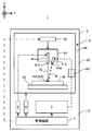
- the modeling system 1 includes a material supply device 3, a modeling device 4, a light source 5, a gas supply device 6, and a control device 7. .
- the material supply device 3, the modeling device 4, the light source 5, the gas supply device 6, and the control device 7 are housed in a housing C.
- the modeling apparatus 4 is accommodated in the upper space UC of the housing C, and the housing in which the material supply device 3, the light source 5, the gas supply device 6 and the control device 7 are located below the upper space UC. It is accommodated in the lower space LC of the body C.
- the arrangement positions of the material supply device 3, the modeling device 4, the light source 5, the gas supply device 6 and the control device 7 in the housing C are not limited to the arrangement positions shown in FIG. 1.
- the material supply device 3 supplies the modeling material M to the modeling device 4.
- the material supply device 3 is adapted to the necessary amount so that the amount of the modeling material M required per unit time to form the three-dimensional structure ST is supplied to the formation device 4. Supply the desired amount of build material M.
- the modeling material M is a material that can be melted by irradiation with light EL having a predetermined intensity or more.
- a modeling material M for example, at least one of a metallic material and a resinous material can be used.
- the shaping material M other materials different from metallic materials and resinous materials may be used.
- the shaping material M is a powdery or granular material. That is, the modeling material M is a granular material.
- the modeling material M may not be a powder, and for example, a wire-shaped modeling material or a gaseous modeling material may be used.
- the modeling apparatus 4 processes the modeling material M supplied from the material supply apparatus 3 to form a three-dimensional structure ST.
- the modeling apparatus 4 includes a modeling head 41, a drive system 42, and a stage 43.
- the forming head 41 includes an irradiation optical system 411 and a material nozzle (that is, a supply system for supplying the forming material M) 412.
- the modeling head 41, the drive system 42, and the stage 43 are accommodated in the chamber 44.
- the irradiation optical system 411 is an optical system (for example, a condensing optical system) for emitting the light EL from the emitting unit 413.
- the irradiation optical system 411 is optically connected to the light source 5 that emits the light EL via a light transmission member (not shown) such as an optical fiber or a light pipe.
- the irradiation optical system 411 emits the light EL propagating from the light source 5 through the light transmission member.
- the irradiation optical system 411 irradiates the light EL from the irradiation optical system 411 downward (that is, on the ⁇ Z side).
- a stage 43 is disposed below the illumination optical system 411.
- the irradiation optical system 411 irradiates the light EL toward the work W. Specifically, the irradiation optical system 411 can irradiate the light EL to the irradiation area EA which is set on the workpiece W as an area to which the light EL is irradiated (typically, condensed). Furthermore, under the control of the control device 7, the state of the irradiation optical system 411 can be switched between the state in which the irradiation area EA is irradiated with the light EL and the state in which the irradiation area EA is not irradiated with the light EL.
- the direction of the light EL emitted from the irradiation optical system 411 is not limited to directly below (that is, coincides with the ⁇ Z-axis direction), for example, even a direction inclined by a predetermined angle with respect to the Z-axis Good.
- the material nozzle 412 has a supply outlet 414 for supplying the build material M.
- the material nozzle 412 supplies (specifically, jets, blows, sprays) the build material M from the supply outlet 414.
- the material nozzle 412 is physically connected to the material supply device 3 which is a supply source of the forming material M via a pipe (not shown) or the like.
- the material nozzle 412 supplies the modeling material M supplied from the material supply device 3 via a pipe.
- the material nozzle 412 may pump the modeling material M supplied from the material supply device 3 via a pipe. That is, the modeling material M from the material supply device 3 and a transport gas (for example, an inert gas such as nitrogen or argon) may be mixed and pressure-fed to the material nozzle 412 through a pipe.
- a transport gas for example, an inert gas such as nitrogen or argon
- the material nozzle 412 is drawn in a tube shape in FIG. 1, the shape of the material nozzle 412 is not limited to this shape.
- the material nozzle 412 supplies the build material M downward (ie, on the ⁇ Z side) from the material nozzle 412.
- a stage 43 is disposed below the material nozzle 412.
- the material nozzle 412 supplies the forming material M toward the workpiece W.
- the traveling direction of the forming material M supplied from the material nozzle 412 is a direction inclined by a predetermined angle (for example, an acute angle) with respect to the Z-axis direction, but even on the -Z side (that is, directly below) Good.
- the material nozzle 412 is aligned with the irradiation optical system 411 such that the modeling material M is supplied toward the irradiation area EA where the irradiation optical system 411 irradiates the light EL. That is, the material nozzle 412 and the irradiation are performed such that the supply area MA and the irradiation area EA set on the workpiece W as the area for the material nozzle 412 to supply the forming material M coincide (or at least partially overlap).
- the optical system 411 is aligned.
- the material nozzle 412 may be aligned so as to supply the modeling material M to the molten pool MP formed by the light EL emitted from the irradiation optical system 411.
- the drive system 42 moves the shaping head 41.
- the drive system 42 moves the modeling head 41 along at least one of the X axis, the Y axis, and the Z axis.
- the irradiation area EA moves on the workpiece W along at least one of the X axis and the Y axis.
- the drive system 42 may move the modeling head 41 along at least one of the ⁇ X direction, the ⁇ Y direction, and the ⁇ Z direction, in addition to at least one of the X axis, the Y axis, and the Z axis.
- the drive system 42 includes, for example, a motor.
- the drive system 42 may move the irradiation optical system 411 and the material nozzle 412 separately. Specifically, for example, the drive system 42 may be able to adjust at least one of the position of the ejection portion 413, the orientation of the ejection portion 413, the position of the supply outlet 414, and the orientation of the supply outlet 414. In this case, an irradiation area EA in which the irradiation optical system 411 irradiates the light EL and a supply area MA in which the material nozzle 412 supplies the modeling material M can be separately controlled.
- the drive system 42 may allow the shaping head 41 to rotate along the rotation axis around the X axis and the rotation axis around the Y axis.
- the stage 43 can hold the work W. Furthermore, the stage 43 can release the held work W.
- the irradiation optical system 411 described above irradiates the light EL in at least a part of a period in which the stage 43 holds the work W.
- the material nozzle 412 described above supplies the build material M in at least a part of a period in which the stage 43 holds the workpiece W.
- a part of the modeling material M supplied by the material nozzle 412 may scatter or spill out from the surface of the workpiece W to the outside of the workpiece W (for example, to the periphery of the stage 43).
- the shaping system 1 may be provided with a recovery device for recovering the scattered or spilled build material M around the stage 43.
- the stage 43 may be provided with a mechanical chuck, a vacuum suction chuck or the like to hold the workpiece W.
- the light source 5 emits, for example, at least one of infrared light, visible light and ultraviolet light as light EL. However, other types of light may be used as the light EL.
- the light EL is a laser light.
- the light source 5 may include a laser light source (for example, a semiconductor laser such as a laser diode (LD: Laser Diode) etc.
- LD Laser Diode
- the laser light source a fiber laser, a CO 2 laser, a YAG laser, an excimer laser, etc.
- the light EL may not be laser light, and the light source 5 may include any light source (for example, at least one of an LED (Light Emitting Diode), a discharge lamp, etc.) .
- the gas supply device 6 is a supply source of purge gas.
- the purge gas contains an inert gas. Nitrogen gas or argon gas is mentioned as an example of inert gas.
- the gas supply device 6 supplies a purge gas into the chamber 44 of the modeling device 4. As a result, the internal space of the chamber 44 becomes a space purged by the purge gas.
- the gas supply device 6 may be a cylinder in which an inert gas such as nitrogen gas or argon gas is stored. When the inert gas is nitrogen gas, the nitrogen gas is generated from the atmosphere as a raw material. It may be a nitrogen gas generator.
- the control device 7 controls the operation of the modeling system 1.
- the control device 7 may include, for example, a central processing unit (CPU) and a memory.
- the control device 7 controls the emission mode of the light EL by the irradiation optical system 411.
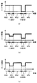
- the emission mode includes, for example, at least one of the intensity of the light EL and the emission timing of the light EL.
- the emission mode includes, for example, at least one of the length of emission time of pulsed light and the ratio of emission time to extinction time of pulsed light (so-called duty ratio). It is also good.
- the control device 7 controls the movement mode of the modeling head 41 by the drive system 42.
- the movement mode includes, for example, at least one of movement amount, movement speed, movement direction, and movement timing. Furthermore, the control device 7 controls the supply mode of the build material M by the material nozzle 412.
- the supply mode includes, for example, at least one of the supply amount (in particular, the supply amount per unit time) and the supply timing.
- the control device 7 may not be provided inside the modeling system 1, and may be provided as a server or the like outside the modeling system 1, for example.
- a forming operation by the forming system 1 (that is, an operation for forming a three-dimensional structure ST) will be described.
- the shaping system 1 forms the three-dimensional structure ST by the laser buildup welding method.
- modeling system 1 may form three-dimensional structure ST by performing existing modeling operation based on a laser build-up welding method.
- an example of the shaping operation of the three-dimensional structure ST by the laser buildup welding method will be briefly described.
- the modeling system 1 forms the three-dimensional structure ST on the workpiece W based on three-dimensional model data (for example, CAD (Computer Aided Design) data) of the three-dimensional structure ST to be formed.
- Contact-type three-dimensional coordinate measuring machine with a probe that can contact the workpiece W Non-contact-type three-dimensional measuring machine (as an example, a pattern projection-type three-dimensional measuring machine, a light cutting-type three-dimensional ⁇ Of-flight 3D measuring machine, moire topographic 3D measuring machine, holographic interference 3D measuring machine, CT (Computed Tomography) 3D measuring machine, MRI (Magnetic resonance imaging) Measurement data of a three-dimensional measuring instrument, etc.
- the modeling system 1 has a three-dimensional structure.
- a plurality of layered partial structures hereinafter, referred to as “structural layers”) SL arranged along the Z-axis direction are sequentially formed.
- a plurality of structural layers SL obtained by slicing the dimensional structure ST along the Z-axis direction are sequentially formed one by one, as a result, it is a laminated structure in which the plurality of structural layers SL are laminated.
- a three-dimensional structure ST is formed A flow of operations for forming a three-dimensional structure ST by sequentially forming a plurality of structural layers SL one by one will be described below.
- the shaping system 1 sets the irradiation area EA in a desired area on the modeling surface CS corresponding to the surface of the workpiece W or the surface of the formed structural layer SL under the control of the control device 7 and for the irradiation area EA.
- the light EL is emitted from the irradiation optical system 411.
- the area occupied by the light EL emitted from the irradiation optical system 411 on the modeling surface CS may be referred to as an irradiation area EA.
- the focus position (that is, the light collection position) of the light EL coincides with the modeling surface CS. As a result, as shown in FIG.
- a molten pool (that is, a pool of metal melted by light EL) MP is formed in a desired region on the modeling surface CS by the light EL emitted from the irradiation optical system 411 Ru. Furthermore, the forming system 1 sets the supply area MA in a desired area on the forming surface CS under the control of the controller 7, and supplies the forming material M from the material nozzle 412 to the supply area MA.
- the supply area MA is set to the area in which the molten pool MP is formed. For this reason, the shaping system 1 supplies the shaping material M to the molten pool MP from the material nozzle 412, as shown in FIG.
- the shaping material M supplied to the molten pool MP is melted.
- the modeling material M melted in the molten pool MP is cooled and solidified again (that is, solidified).
- the resolidified shaping material M is deposited on the shaping surface CS. That is, a shaped object is formed by the deposit of the modeling material M resolidified.
- a series of shaping processes including formation of the molten pool MP by such light irradiation EL, supply of the forming material M to the molten pool MP, melting of the supplied forming material M, and resolidification of the molten forming material M,
- the process is repeated while moving the modeling head 41 relative to the modeling surface CS along the XY plane. That is, when the modeling head 41 moves relative to the modeling surface CS, the irradiation area EA also moves relative to the modeling surface CS. Therefore, a series of formation processing is repeated while moving the irradiation area EA relative to the formation surface CS along the XY plane (that is, in a two-dimensional plane).
- the modeling system 1 moves the irradiation area EA along the predetermined movement trajectory on the modeling surface CS and at a timing according to the distribution pattern of the area where the modeling object is desired to be formed (that is, the pattern of the structural layer SL).
- the light EL is applied to the shaped surface CS.
- the molten pool MP also moves on the modeling surface CS along the movement trajectory according to the movement trajectory of the irradiation area EA.
- the molten pool MP is sequentially formed on a portion of the region along the movement trajectory of the irradiation region EA on the modeling surface CS where the light EL is irradiated.
- the supply area MA also moves on the modeling surface CS along the movement locus according to the movement locus of the irradiation area EA. Become.
- a structural layer SL corresponding to an aggregate of shaped objects by the solidified shaped material M is formed on the shaped surface CS.
- a structural layer SL corresponding to an aggregate of shaped objects formed on the modeling surface CS in a pattern according to the movement trajectory of the molten pool MP ie, a shape according to the movement trajectory of the molten pool MP in plan view
- the structural layer SL is formed.
- irradiation area EA is set to the area which does not want to form a modeling thing, while irradiating light EL to irradiation area EA, supply of modeling material M may be stopped.
- the modeling material M is supplied to the irradiation area EL, and the irradiation area EL is irradiated with the light EL having an intensity that the molten pool MP can not be used. May be
- the irradiation area EA is, as shown in FIG. 3A, the movement of the irradiation area EA along the Y-axis direction and X
- the movement of the irradiation area EA along the axial direction may be repeated along a first movement locus that is repeated.
- the irradiation area EA is the movement of the irradiation area EA to the + Y side, the movement of the irradiation area EA to the + X side, the movement of the irradiation area EA to the -Y side, and the irradiation area EA.
- the modeling system 1 irradiates the light EL at a timing when the irradiation area EA is set to the area on which the modeling object is to be formed on the modeling surface CS.
- the movement amount of the irradiation area EA along the Y-axis direction in particular, the movement amount for one movement until the movement direction of the irradiation area EA switches to the X-axis direction
- the movement amount of the irradiation area EA along the X-axis direction is larger.
- the shaping system 1 is configured such that the irradiation area EA is along the Y axis (or one of the X axis and the Y axis that has a large amount of movement of one movement of the irradiation area EA).
- the light EL is irradiated during the moving period, and the irradiation area EA is along the X axis (or the X axis and the Y axis, or the other of the X axis and the Y axis, which has a small moving amount of one movement of the irradiation area EA).
- 3A can be said to be a movement locus corresponding to scanning in a so-called raster scan.
- the possibility that the movement locus of the irradiation area EA intersects on the modeling surface CS is not limited to zero, the movement locus of the irradiation area EA hardly intersects.
- the irradiation area EA may move along a second movement trajectory along the pattern of the structural layer SL, as shown in FIG. 3 (b). Also in this case, the modeling system 1 irradiates the light EL at the timing when the irradiation area EA is set to the area on which the modeling object is to be formed on the modeling surface CS. However, since the irradiation area EA moves along the second movement locus along the pattern of the structural layer SL, the irradiation area EA substantially corresponds to an area where it is desired to form a shaped object on the modeling surface CS. It can be said that they almost overlap.
- the shaping system 1 may continue to emit the light EL while the irradiation area EA is moving.
- the molten pool MP also moves along the second movement trajectory along the pattern of the structural layer SL.
- a shaping process is performed to grow the shaped object in the direction in which the irradiation area EA moves relative to the structural layer SL.
- the movement locus shown in FIG. 3B can be said to be a movement locus corresponding to a so-called vector scan.
- the control device 7 moves the irradiation area EA so that the movement locus of the irradiation area EA does not intersect on the modeling surface CS (in particular, the movement locus of the molten pool MP does not intersect on the modeling surface CS)
- the trajectory may be set. However, depending on the distribution pattern on the modeling surface CS of the area where it is desired to form a shaped object, the movement locus of the irradiation area EA (in particular, the movement locus of the molten pool MP) may intersect on the modeling surface CS.
- the irradiation area EA is moved with respect to the modeling surface CS by moving the modeling head 41 (that is, the light EL) with respect to the modeling surface CS, but the modeling surface CS may be moved. , And both the shaping head 41 (i.e., the light EL) and the shaping surface CS may be moved.
- the modeling system 1 repeatedly performs an operation for forming such a structural layer SL based on three-dimensional model data under the control of the control device 7. Specifically, first, three-dimensional model data is sliced at a lamination pitch to create slice data. In addition, you may use the data which corrected this slice data partially according to the characteristic of the modeling system 1.
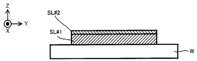
- FIG. The modeling system 1 performs an operation for forming the first structural layer SL # 1 on the modeling surface CS corresponding to the surface of the workpiece W, ie, three-dimensional model data corresponding to the structural layer SL # 1, ie, a structural layer This is performed based on slice data corresponding to SL # 1. As a result, as shown in FIG. 4A, the structural layer SL # 1 is formed on the shaped surface CS.
- the modeling system 1 sets the surface (that is, the upper surface) of the structural layer SL # 1 to the new modeling surface CS, and then forms the second structural layer SL # 2 on the new modeling surface CS.
- the control device 7 first controls the drive system 42 so that the modeling head 41 moves along the Z axis. Specifically, the controller 7 controls the drive system 42 so that the irradiation area EA and the supply area MA are set to the surface of the structural layer SL # 1 (that is, the new formed surface CS), + Z.
- the shaping head 41 is moved toward the side. Thereby, the focus position of light EL corresponds to the new modeling surface CS.
- modeling system 1 performs an operation similar to the operation of forming structural layer SL # 1 under the control of control device 7, and based on slice data corresponding to structural layer SL # 2, on structural layer SL # 1.
- a structural layer SL # 2 is formed.
- the same operation is repeated until all structural layers SL constituting the three-dimensional structure ST to be formed on the work W are formed.
- a three-dimensional structure ST is formed by a laminated structure in which a plurality of structural layers SL are laminated.
- the variation suppressing control operation for suppressing the variation in the characteristics of the shaped object (that is, the shaped object constituting each structural layer SL) formed by the shaping operation will be described.
- the modeling system 1 performs at least one of the first variation suppression operation, the second variation suppression operation, the third variation suppression operation, and the fourth variation suppression operation. Therefore, hereinafter, the first variation suppression operation to the fourth variation suppression operation will be described in order.
- the height from the shaped surface CS of the shaped object that is, the size in the Z-axis direction or the size in the Z-axis direction
- substantially the thickness of the shaped object Shall be used. That is, in the following description, the variation suppressing operation for suppressing the variation in the height of the shaped object will be described.
- any characteristic other than the height of the shaped object may be used as the characteristic of the shaped object.
- the size of the shaped object along the shaped surface CS (that is, the size of at least one of the X axis direction and the Y axis direction
- the width may be used.
- the first variation suppressing operation is performed when the irradiation area EA is set twice or more in the same area on the modeling surface CS during the layer formation period in which one arbitrary structural layer SL is formed on the modeling surface CS. , Corresponds to the operation for suppressing the variation in height of the shaped object.
- the height for each position in the surface where the structural layer SL is located in any one structural layer SL (the size in the direction intersecting the surface where the structural layer SL is located) It may be an operation for suppressing the variation.
- the irradiation area EA is a structural layer on the modeling surface CS. It moves on the modeling surface CS along the movement trajectory according to the SL pattern.
- the movement locus of the irradiation area EA intersects on the shaped surface CS.
- the irradiation area EA is set twice or more in the area WA1 on the shaped surface CS where the movement locus of the irradiation area EA intersects.
- the irradiation area EA is set only once in the area WA2 on the modeling surface CS where the movement locus of the irradiation area EA does not intersect while overlapping the movement locus of the irradiation area EA. That is, the formed surface CS includes the area WA1 in which the irradiation area EA is set twice or more during the layer formation period, and the area WA2 in which the irradiation area EA is set only once during the layer formation period.
- the region WA1 can be set as the region in which the irradiation region EA is set M times (M is an integer of 2 or more) during the layer formation period, and the region WA2 is N times the irradiation region EA during the layer formation period
- a region may be set (N is an integer of 1 or more and satisfies the relationship of N ⁇ M).
- the number of modeling processes for the area WA1 is different from the number of modeling processes for the area WA2, and specifically, the number of modeling processes for the area WA1 is larger than the number of modeling processes for the area WA2.
- the number of modeling processes for the area WA2 is smaller than the number of modeling processes for the area WA1.
- a series of formation including formation of the molten pool MP by irradiation of light described above, supply of the forming material M to the molten pool MP, melting of the supplied forming material M and resolidification of the molten forming material M
- the processing may be performed twice or more at different timings in which the area WA1 coincides with at least a part of the irradiation area EA. That is, in the area WA1, there is a possibility that the movement loci of the molten pool MP on the shaped surface CS intersect. On the other hand, in the area WA2, a series of modeling processing is not performed twice or more.
- a series of modeling processing is performed at most only once. That is, in the area WA2, the movement trajectories of the molten pool MP on the shaped surface CS do not intersect.
- the layer formation period forming one structural layer SL at least a part of the molten pool MP formed for the second and subsequent modeling processing is formed in the area WA1 by the first modeling processing. It may be formed into a shaped object. That is, at least a part of the molten pool MP formed for the second and subsequent modeling processing may be formed of the modeling material M.
- the series of shaping processes is performed twice or more in the area WA1 while the series of shaping processes is performed only once in the area WA2.
- the number of times of shaping processes on the area WA1 and the shaping processes to the area WA2 The following technical issues arise if the number of times is different. Specifically, in the area WA1, more shaping material M may be supplied, melted and re-solidified as compared to the area WA2.
- the formation formed in the area WA1 There is a possibility that the height of the object and the height of the shaped object formed in the area WA2 do not match.
- the height h1 of the shaped object formed in the area WA1 is the shaped object formed in the area WA2 as many times as the series of shaping processing is performed May be higher than the height h2.
- the height of the modeled object may vary.
- the shaped object formed in the region WA1 is referred to as "the shaped object S1"
- the shaped object formed in the region WA2 is referred to as the "shaped object S2”.
- the control device 7 (in other words, the shaping system 1 under control of the control device 7) performs the first variation suppressing operation to obtain the height h1 of the shaped object S1 and the shaped object S2 To reduce the variation with the height h2.
- the operation “suppressing the variation between the height of one shaped object and the height of another shaped object” is higher in height of one shaped object than in the case where the variation suppressing operation is not performed. Includes an operation to reduce the difference between the height and the height of the other object (that is, to reduce the difference).
- the action “suppress the variation between the height of one shaped object and the height of another shaped object” makes the motion of matching the height of one shaped object with the height of another shaped object (that is, identical). Including.
- the size of the shaped object formed in the region WA1 (here, in the X-axis direction)
- the size, substantially the width) w1 becomes larger than the size w2 of the shaped object formed in the area WA2. That is, when the irradiation area EA is set twice or more in a certain area on the modeling surface CS during the layer formation period, there is a possibility that the size of the modeled object may vary.
- the size of the shaped object (particularly, the size along the XY plane) can be a characteristic of the shaped object whose variation should be suppressed by the first variation suppressing operation.
- the first variation suppressing operation is an operation for suppressing the variation in the size in the direction along the surface in each position in the surface where the structural layer SL is located in any one structural layer SL. It may be Conversely, if a series of modeling processes are performed without distinguishing the area WA1 and the area WA2 in a situation where a shaped object having the same characteristic is to be formed in the area WA1 and the area WA2, the area WA1 is formed.
- any characteristic satisfying the condition that the characteristic of the object and the characteristic of the object formed in the area WA2 may not coincide with each other is the characteristic of the object to suppress the variation by the first variation suppressing operation. It may be used. The same applies to the second to fourth variation suppression operations described below.
- the controller 7 controls (for example, adjusts, changes or sets, for example, the same applies hereinafter) the supply amount of the modeling material M supplied per unit time with respect to the supply area MA (that is, the irradiation area EA or the molten pool MP).
- the first variation suppressing operation may be performed to reduce the variation of the height of the shaped object.
- the supply amount of the modeling material M supplied per unit time with respect to the supply area MA will be referred to as a “supply rate” for convenience of description.
- a unit of the supply amount of the modeling material M you may use weight or volume.
- the controller 7 controls the amount of heat transferred from the light EL to the modeling surface CS per unit time via the irradiation area EA (that is, the supply area MA) in addition to or instead of controlling the supply rate. Then, the first variation suppression operation may be performed to suppress the variation of the height of the shaped object.
- the amount of heat transferred from the light EL to the shaped surface CS per unit time via the irradiation area EA will be referred to as a “heat transfer rate” for the convenience of description.
- the controller 7 relatively moves the irradiation area EA (that is, the supply area MA or the molten pool MP) relative to the shaped surface CS.
- FIG. 6A to FIG. 6C is a graph in which the horizontal axis represents time and the vertical axis represents the supply rate of the modeling material M. Since the irradiation area EA moves on the formation surface CS with the passage of time, the horizontal axes of FIGS. 6A to 6C substantially set the irradiation area EA on the formation surface It corresponds to the position. In other words, each of FIG. 6A to FIG. 6C shows the supply rate of the modeling material M to the area portion during the period in which the irradiation area EA is set in the certain area portion on the modeling surface CS. ing.
- the controller 7 determines that (i) the supply rate for the area WA1 is the same as the supply rate for the area WA2 during the period in which the irradiation area EA is set for the first time in the area WA1. And (ii) the supply rate may be controlled such that the supply rate for the area WA1 is zero during the period in which the irradiation area EA is set for the second time to the area WA1.
- the supply rate for the area WA1 for which the irradiation area EA is set for the first time is the same as the supply rate for the area WA2, and (ii) the area for which the irradiation area EA is set again
- the supply rate may be controlled such that the supply rate for WA1 is zero.
- the control device 7 may control the supply rate so that the supply rate for the area WA1 in which the irradiation area EA is set again is lower than the supply rate for the area WA1 in which the irradiation area EA is set for the first time. .
- the controller 7 determines that (i) the supply rate for the area WA1 in the period in which the irradiation area EA is set for the second time to the area WA1 is the same as the supply rate for the area WA2, and (ii) the area The supply rate may be controlled so that the supply rate for the area WA1 becomes zero during the period in which the irradiation area EA is set for the first time to WA1. That is, the controller 7 determines that (i) the supply rate for the area WA1 in which the irradiation area EA is set at a certain timing is the same as the supply rate for the area WA2, and (ii) the irradiation area EA at another timing.
- the supply rate may be controlled such that the supply rate for the area WA1 in which is set is zero. Also in the case where the irradiation area EA is set twice or more in the area WA1 during the layer formation period, the controller 7 similarly (i) supplies the supply rate to the area WA1 in which the irradiation area EA is set at a certain timing The supply rate may be controlled so that it becomes the same as the supply rate for WA2 and (ii) the supply rate for the area WA1 where the irradiation area EA is set is zero at other timing.
- the control device 7 determines that the supply rate for the area WA1 for which the irradiation area EA is set at a certain timing is the same as the supply rate for the area WA2, and for the area WA1 for which the irradiation area EA is set at other timings.
- the feed rate may be controlled such that the feed rate is lower than the feed rate for the area WA2.
- the total amount of the modeling material M supplied to the region WA1 during the layer formation period is the same as the total amount of the modeling material M supplied to the region WA2 during the layer formation period . More specifically, the total amount of the modeling material M supplied to the area WA1 of a certain size during the layer formation period and the total amount of the modeling material M supplied to the area WA2 of the same size during the layer formation period are It will be the same.
- a value obtained by dividing the total amount of the modeling material M supplied to the region WA1 during the layer formation period by the area of the region WA1 (that is, the supply amount of the modeling material M per unit area) Is the same as the value obtained by dividing the total amount of the modeling material M supplied to the area by the area of the area WA2. Therefore, in the area WA1 and the area WA2, the same amount of the modeling material M is supplied, melted, and resolidified per unit area. As a result, the variation between the height h1 of the three-dimensional object S1 formed in the area WA1 and the height h2 of the three-dimensional object S2 formed in the area WA2 is suppressed.
- the supply rate of the modeling material M may be controlled in consideration of this non-linear relationship.
- the supply rate may be controlled in consideration of the non-linear relationship.
- the control device 7 supplies the forming material M to the area WA1 every time the irradiation area EA is set in the area WA1 (ie, The supply rate may be controlled so that the supply rate to the area WA1 does not become zero).
- the control device 7 supplies the supply rate to the area WA1 during the period in which the irradiation area EA is set for the first time in the area WA1, and the area WA1 for the period in which the irradiation area EA is set for the second time in the area WA1.
- the supply rate is controlled so that both of the supply rates for ⁇ ⁇ ⁇ ⁇ ⁇ are smaller than the supply rate for the area WA2. As shown in FIG.
- the control device 7 supplies the supply rate to the area WA1 during the period in which the irradiation area EA is set for the first time in the area WA1, and the irradiation area EA for the second time in the area WA1.
- the supply rate may be controlled to be different from the supply rate for the area WA1 in the set period.
- the control device 7 supplies the supply rate to the area WA1 during the period in which the irradiation area EA is set for the first time in the area WA1, and the irradiation area EA for the second time in the area WA1.
- the supply rate may be controlled to be the same as the supply rate for the area WA1 during the set period.
- the layer formation is compared with the case where the supply rate for the area WA1 and the supply rate for the area WA2 are always the same.
- the difference between the total amount of the modeling material M supplied to the region WA1 during the period and the total amount of the modeling material M supplied to the region WA2 during the layer formation period is reduced.
- the variation between the height h1 of the three-dimensional object S1 formed in the area WA1 and the height h2 of the three-dimensional object S2 formed in the area WA2 is suppressed.
- control device 7 controls the supply rate so that the modeling material M is supplied to the area WA1 every time the irradiation area EA is set in the area WA1, the control supplied to the area WA1 during the layer formation period With respect to the area WA1 in the period in which the irradiation area EA is set for the first time in the area WA1, so that the total amount of the material M and the total amount of the forming material M supplied to the area WA2 during the layer formation period become the same.
- the supply rate and the supply rate to the area WA1 during the period in which the irradiation area EA is set for the second time to the area WA1 may be controlled. As a result, as in the case where the supply rate is controlled as shown in FIG.
- the total amount of the modeling material M supplied to the area WA1 during the layer formation period and the area WA2 are supplied during the layer formation period It becomes the same as the total amount of the shaping material M.
- the variation between the height h1 of the three-dimensional object S1 formed in the area WA1 and the height h2 of the three-dimensional object S2 formed in the area WA2 is more appropriately suppressed.
- the supply rate may be controlled in consideration of this non-linear relationship.
- the supply rate may be controlled in consideration of the non-linear relationship.
- the control device 7 supplies the area WA1 in each period in which the irradiation area EA is set in the area WA1.
- the supply rate may be controlled so that the rate is smaller than the supply rate for the area WA2.
- the control device 7 controls the region so that the total amount of the modeling material M supplied to the region WA1 during the layer formation period is the same as the total amount of the modeling material M supplied to the region WA2 during the layer formation period.
- the supply rate to the area WA1 may be controlled in each period in which the irradiation area EA is set to WA1. Note that the supply rate may be controlled so that the total amount of the modeling material M supplied to the region WA1 during the layer formation period and the total amount of the modeling material M supplied to the region WA2 during the layer formation period are different. .
- the controller 7 may control the supply amount (that is, the injection amount) of the build material M from the material nozzle 412 per unit time to control the supply rate. Specifically, as shown in FIG. 7, as the supply amount of the modeling material M from the material nozzle 412 per unit time increases, the supply rate increases. For this reason, the control device 7 can control the supply rate by controlling the supply amount of the modeling material M from the material nozzle 412 per unit time.
- the controller 7 controls the material supply device 3 to control the supply amount of the build material M per unit time from the material nozzle 412 so that the unit of the build material M from the material supply device 3 to the material nozzle 412 The supply rate per hour may be controlled.
- the controller 7 may control the material nozzle 412 in order to control the supply amount of the building material M per unit time from the material nozzle 412.
- the control device 7 controls the valve to generate the build material from the material nozzle 412.
- the supply amount per unit time of M may be controlled.
- the controller 7 supplies at least a part of the shaping material M supplied from the material nozzle 412 to the supply area MA (ie, to control the supply rate.
- You may control the gas injection apparatus 461 with which the modeling apparatus 4 is equipped, in order to blow off before reaching the irradiation area
- the gas ejection device 461 ejects an inert gas toward at least a part of the supply path of the build material M between the material nozzle 412 and the supply area MA.
- the gas ejection device 461 may eject the inert gas along a direction intersecting the direction of the supply path of the build material M between the material nozzle 412 and the supply area MA.
- the inert gas ejected by the gas ejection device 461 is supplied from the gas supply device 6 to the gas ejection device 461, for example.
- the gas ejection device 461 ejects an inert gas, as shown in FIG. 8A, at least a part of the modeling material M supplied from the material nozzle 412 reaches the supply area MA. Before, it is blown away from the supply area MA. That is, at least a portion of the modeling material M supplied from the material nozzle 412 does not reach the supply area MA.
- the gas ejection device 461 does not eject the inert gas, as shown in FIG. 8B, the shaping material M supplied from the material nozzle 412 is blown away from the supply area MA.
- the modeling material M supplied from the material nozzle 412 reaches the supply area MA.
- the gas ejection device 461 ejects the inert gas, compared with the case where the gas ejection device 461 does not eject the inert gas, per unit time of the modeling material M with respect to the supply area MA Supply will be reduced. That is, when the gas ejection device 461 ejects the inert gas, the supply rate is smaller than when the gas ejection device 461 does not eject the inert gas.
- the control device 7 can control the supply rate by controlling the gas injection device 461.
- the controller 7 can be inserted into or removed from the supply path of the shaping material M between the material nozzle 412 and the supply area MA in order to control the supply rate.
- the shielding member 462 disposed in the modeling apparatus 4 may be controlled. Specifically, the shielding member 462 is movable relative to the supply path of the modeling material M by a drive system (for example, an actuator etc.) (not shown). Note that the shielding member 462 may be movable along a direction intersecting the direction of the supply path of the build material M between the material nozzle 412 and the supply area MA. With the movement of the shielding member 462, the shielding member 462 is in the non-shielding state (see FIG.
- the shielding member 462 does not block the supply path of the modeling material M; It is switchable between the shielding state (refer FIG.9 (b)) which has interrupted the supply path.
- the shielding member 462 is in the non-shielding state, as shown in FIG. 9A, the modeling material M supplied from the material nozzle 412 reaches the supply area MA without being blocked by the shielding member 462 .
- the shielding member 462 is in the shielding state, as shown in FIG. 9B, before at least a part of the modeling material M supplied from the material nozzle 412 reaches the supply area MA, It is interrupted by the shielding member 462.
- the control device 7 can control the supply rate of the modeling material M by controlling the shielding member 462.
- the shielding member 462 may be in a semi-shielding state in which the shielding member 462 blocks a part of the supply path of the modeling material M.
- the state of the shielding member 462 may be controlled so that the modeling material M is intermittently supplied to one supply area MA.
- the ratio of the non-shielding state to the shielding state (duty ratio) may be controlled to control the amount of supply of the modeling material M per unit time to the one supply area MA. At this time, the time of each of the unshielded state and the shielded state may be shorter than the unit time.
- the gas injection device 461 and the shielding member 462 are both supply amount change devices for suppressing at least a part of the modeling material M supplied from the material nozzle 412 from reaching the supply area MA. .
- the control device 7 optionally controls the supply rate of the modeling material M.
- the supply amount change device of In addition, an arbitrary supply amount change device may be provided in at least one of the material supply device 3 and the supply path from the material supply device 3 to the supply outlet 414 of the material nozzle 412. As such a supply rate change device, for example, a valve capable of changing the passing flow rate may be used.
- such a valve capable of changing the passing flow rate may be provided in at least one of the material supply device 3 and the supply passage.
- a valve for example, a butterfly valve, a gate valve, a globe valve, a ball valve or the like may be used.
- the controller 7 may control the supply direction (that is, the injection direction) of the build material M from the material nozzle 412 in order to control the supply rate. Specifically, as shown in FIGS. 10A and 10B, the control device 7 controls the direction of the material nozzle 412 with respect to the modeling surface CS to make it possible to form the molding material M from the material nozzle 412.
- the feed direction may be controlled.
- the orientation of the material nozzle 412 can be controlled by moving the material nozzle 412 using the drive system 42. However, in this case, the drive system 42 moves the irradiation optical system 411 and the material nozzle 412 separately.
- the state of the material nozzle 412 can be supplied to the supply area MA (that is, the irradiation area EA or the molten pool MP) so as to supply the modeling material M (see FIG. 10A).
- the non-supplying state in which the modeling material M can not be supplied toward the supply area MA (that is, the irradiation area EA or the molten pool MP).
- the modeling material M supplied from the material nozzle 412 does not reach the supply area MA. Therefore, the longer the period in which the material nozzle 412 is in the non-supply state, the smaller the supply amount of the build material M per unit time to the supply area MA. That is, the longer the period in which the material nozzle 412 is in the non-supply state, the lower the supply rate of the build material M. For this reason, the control device 7 can control the supply rate of the build material M by controlling the supply direction of the build material M.
- the state of the material nozzle 412 may be a half-supply state in which the modeling material M can be supplied toward a part of the supply area MA (that is, the irradiation area EA or the molten pool MP). In this case, the area of the part where the build material is supplied from the material nozzle 412 may be changed to control the supply rate of the build material M.
- FIGS. 11A to 11C shows the supply rate of the molding material M when the irradiation area EA is set twice in the area WA1 during the layer formation period. Shows a control method of
- FIGS. 11 (a) to 11 (c) is a graph in which the horizontal axis represents time and the vertical axis represents the heat transfer rate. Since the irradiation area EA moves on the shaped surface CS with the passage of time, the horizontal axes in FIGS. 11A to 11C correspond to the horizontal axes in FIGS. 6A to 6C described above. Similarly, it corresponds to the position where the irradiation area EA is set on the modeling surface CS.
- the controller 7 determines that (i) the heat transfer rate to the area WA1 during the period in which the irradiation area EA is set for the first time to the area WA1 is the heat transfer rate to the area WA2 and The heat transfer rate may be controlled so that the heat transfer rate with respect to the area WA1 becomes zero during the same period and (ii) the irradiation area EA is set for the second time in the area WA1.
- the control device 7 applies the light EL to the area WA1 for which (i) the irradiation area EA is set for the first time in the same manner as the area WA2, and (ii) the area for which the irradiation area EA is set again.
- the modeling apparatus 4 is controlled so as not to irradiate the light EL to the WA1.
- the control device 7 controls the heat transfer rate so that the heat transfer rate to the area WA1 for which the irradiation area is set for the second time is lower than the heat transfer rate for the area WA1 for which the irradiation area is set for the first time.
- the control device 7 controls the intensity or energy per unit time of the light EL for the region WA1 for which the irradiation region is set for the second time, or the intensity for unit light of the light EL for the region WA1 for which the irradiation region is set for the first time Alternatively, it may be controlled to be lower than energy.
- the controller 7 determines that (i) the heat transfer rate to the area WA1 during the period in which the irradiation area EA is set for the second time to the area WA1 is the same as the heat transfer rate to the area WA2;
- the heat transfer rate may be controlled so that the heat transfer rate to the area WA1 becomes zero during the period in which the irradiation area EA is set to the area WA1 for the first time. That is, in the control device 7, (i) the heat transfer rate to the area WA1 in which the irradiation area EA is set at a certain timing becomes the same as the heat transfer rate to the area WA2, and (ii) the irradiation is performed at other timings.
- the heat transfer rate may be controlled so that the heat transfer rate to the area WA1 where the area EA is set is zero. Similarly, even when the irradiation area EA is set twice or more in the area WA1 during the layer formation period, the controller 7 (i) sets the heat transfer rate to the area WA1 in which the irradiation area EA is set at a certain timing. The heat transfer rate may be controlled to be the same as the heat transfer rate for the area WA2 and (ii) the heat transfer rate for the area WA1 where the irradiation area EA is set to be zero at other timings. .
- the control device 7 controls the heat transfer rate so that the heat transfer rate to the area WA1 in which the irradiation area is set for the first time is lower than the heat transfer rate for the area WA1 in which the irradiation area is set for the second time. You may In addition, the control device 7 controls the intensity or energy per unit time of the light EL for the region WA1 for which the irradiation region is set for the first time or the intensity for light unit for the region WA1 for which the irradiation region is set for the second time. Alternatively, it may be controlled to be lower than energy.
- the heat transfer rate to the area WA1 in which the irradiation area EA is set at a certain timing is the same as the heat transfer rate to the area WA2, and the area in which the irradiation area EA is set at other timings.
- the heat transfer rate may be controlled such that the heat transfer rate for WA1 is lower than the heat transfer rate for area WA2.
- the total amount of heat transferred from the light EL to the area WA1 during the layer formation period and the total amount of heat transferred from the light EL to the area WA2 during the layer formation period are It will be the same. More specifically, the total amount of heat transferred from the light EL to the area WA1 of a certain size during the layer formation period and the total amount of heat transferred from the light EL to the area WA2 of the same size during the layer formation period And will be the same.
- a value obtained by dividing the total amount of heat transferred from the light EL to the region WA1 during the layer formation period by the area of the region WA1 (that is, the amount of heat transferred from the light EL per unit area)
- the total amount of heat transferred from the light EL to the area WA2 is the same as the value obtained by dividing the area by the area WA2. Therefore, in the area WA1 and the area WA2, the same amount of the modeling material M is supplied, melted, and resolidified per unit area.
- the reason is that there is a possibility that a larger amount of the modeling material M may be melted as the amount of heat transferred from the light EL increases, and the total amount of heat transferred from the light EL to the area WA1 and the heat from the light EL to the area WA2 Since the total amount of heat applied is the same, the amount of melting of the shaping material M in the area WA1 (specifically, the amount of melting per unit area, the same applies hereinafter) and the melting amount of the shaping material M in the area WA2 are It is because the possibility of becoming the same is relatively high.
- the heat transfer rate may be controlled in consideration of this non-linear relationship.
- a molten pool MP having the same size as the area WA2 is formed in the area WA1. This is because there is a possibility that a larger molten pool MP is formed as the amount of heat transferred from the light EL increases, and the total amount of heat transferred from the light EL to the area WA1 and the heat transferred from the light EL to the area WA2 The reason is that the size of the molten pool MP formed in the area WA1 and the size of the molten pool MP formed in the area WA2 are relatively likely to be the same.
- the variation between the height h1 of the object S1 formed in the area WA1 and the height h2 of the object S2 formed in the area WA2 is suppressed. .
- a relatively high shaped object may be formed.
- the size of the molten pool MP formed in the area WA1 and the size of the molten pool MP formed in the area WA2 are the same, the height h1 of the object S1 formed in the area WA1 And the variation in height h2 of the object S2 formed in the area WA2 are suppressed. As a result, the formation accuracy of the three-dimensional structure ST, which is an assembly of three-dimensional objects, is improved.
- the control device 7 causes the area WA1 to be irradiated with the light EL each time the irradiation area EA is set in the area WA1 (ie, the area
- the heat transfer rate may be controlled so that the heat transfer rate to WA1 does not become zero.
- the controller 7 controls the heat transfer rate to the area WA1 during the first setting of the irradiation area EA in the area WA1, and the area during the second setting of the irradiation area EA in the area WA1.
- the supply rate of the build material M is controlled such that both of the heat transfer rates for WA1 are smaller than the heat transfer rate for the area WA2. As shown in FIG.
- the controller 7 controls the heat transfer rate to the area WA1 during the first setting of the irradiation area EA in the area WA1, and the second irradiation area EA in the area WA1.
- the heat transfer rate may be controlled so that the heat transfer rate to the area WA1 is different from the time period in which the ⁇ is set.
- the control device 7 sets the heat transfer rate to the area WA1 during the first setting of the irradiation area EA in the area WA1 and the second irradiation area EA in the area WA1.
- the heat transfer rate may be controlled so that the heat transfer rate with respect to the area WA1 in the period in which is set is the same.
- the heat transfer rate for the area WA1 and the heat transfer rate for the area WA2 are always equal to each other.
- the difference between the total amount of heat transferred to the region WA1 during the layer formation period and the total amount of heat transferred to the region WA2 during the layer formation period decreases.
- the variation between the height h1 of the three-dimensional object S1 formed in the area WA1 and the height h2 of the three-dimensional object S2 formed in the area WA2 is suppressed. If the relationship between the heat transfer rate and the heights h1 and h2 of the object is nonlinear, the heat transfer rate may be controlled in consideration of this non-linear relationship.
- the control device 7 controls the heat transfer rate such that the light EL is irradiated to the area WA1 every time the irradiation area EA is set to the area WA1, the heat transmitted to the area WA1 during the layer formation period And the heat transfer rate to the area WA1 during the period when the irradiation area EA is set for the first time in the area WA1 so that the total amount of heat transferred to the area WA2 during the layer formation period becomes the same.
- the heat transfer rate to the area WA1 may be controlled during the period in which the irradiation area EA is set for the second time in the area WA1. As a result, as in the case where the heat transfer rate is controlled as shown in FIG.
- the total amount of heat transferred to the area WA1 during the layer formation period and the area WA2 are transmitted during the layer formation period.
- the total amount of heat is the same.
- the variation between the height h1 of the shaped object S1 formed in the area WA1 and the height h2 of the shaped object S2 formed in the area WA2 is more appropriately suppressed.
- the control device 7 similarly heats the area WA1 in each period in which the irradiation area EA is set in the area WA1.
- the heat transfer rate may be controlled so that the transfer rate is smaller than the heat transfer rate for the area WA2.
- the control device 7 irradiates the area WA1 with the irradiation area such that the total amount of heat transferred to the area WA1 during the layer formation period is the same as the total amount of heat transmitted to the area WA2 during the layer formation period.
- the heat transfer rate to the area WA1 may be controlled during each period in which the EA is set.
- the controller 7 may control the intensity or energy amount per unit area of the light EL on the irradiation area EA in order to control the heat transfer rate. Specifically, as shown in FIG. 12, the heat transfer rate increases as the intensity or energy amount per unit area of the light EL on the irradiation area EA increases. Therefore, the control device 7 can control the heat transfer rate by controlling the intensity or the energy amount per unit area of the light EL on the irradiation area EA.
- the controller 7 may control the light source 5 in order to control the intensity per unit area of the light EL on the irradiation area EA.
- the control device 7 may control the intensity of the light EL emitted by the light source 5.
- the intensity per unit area of the light EL on the irradiation area EA increases as the emission time of the pulse light increases (in other words, as the extinction time of the pulse light decreases). . Therefore, when the light EL is pulse light, for example, the control device 7 may control the duty ratio of the light EL emitted by the light source 5.
- the control device 7 may control the irradiation optical system 411 in order to control the intensity or energy amount per unit area of the light EL on the irradiation area EA.
- the control device 7 may control the intensity or the energy amount of the light EL emitted by the irradiation optical system 411.
- the irradiation optical system 411 may include an optical member for adjusting the intensity or energy amount of the light EL in the irradiation optical system 411.
- the control device 7 performs irradiation with the irradiation optical system 411 as shown in FIGS. 13 (a) and 13 (b).
- the light blocking member 471 disposed in the modeling apparatus 4 may be controlled so as to be insertable into and removable from the light path of the light EL between the area EA.
- the light shielding member 471 is movable with respect to the light path of the light EL by a drive system (for example, an actuator or the like) (not shown). With the movement of the light blocking member 471, the light blocking member 471 is in the light blocking state blocking the light path of the light EL (see FIG.
- the light shielding member 471 may be controlled by the control device 7 to be in a semi-light shielding state in which a part of the light EL emitted from the irradiation optical system 411 is shielded.
- the control device 7 may control the ratio between the period in which the light shielding member 471 is in the light shielding state and the period in which the light shielding member 471 is in the non-light shielding state. The longer the period in which the light shielding member 471 is in the light shielding state (in other words, the shorter the period in which the light shielding member 471 is in the non-light shielding state), the smaller the intensity per unit area of the light EL on the irradiation area EA.
- the light shielding member 471 may be provided inside the irradiation optical system 411, or may be provided in the optical path between the light source 5 and the irradiation optical system 411.
- the control device 7 may control the focus position (in other words, the defocus amount) of the light EL in order to control the heat transfer rate.
- the focus position in other words, the defocus amount
- the intensity or energy amount per unit area of the light EL on the irradiation area EA set on the modeling surface CS increases as the focus position moves away from the modeling surface CS (that is, as the defocus amount increases). It becomes smaller. Therefore, the heat transfer rate decreases as the focus position moves away from the modeling surface CS (that is, as the defocus amount increases). Therefore, the control device 7 can control the heat transfer rate by controlling the focus position.
- the control device 7 may control the condensing optical element 472 provided in the irradiation optical system 411. FIG.
- the controller 7 may control the drive system 42 in order to control the focus position. Specifically, the control device 7 moves the modeling head 41 (in particular, the irradiation optical system 411) along the Z axis with respect to the modeling surface CS, to thereby obtain the relative position between the modeling surface CS and the focus position.
- the controller 7 controls the stage 43 (that is, the modeling surface CS) along the Z axis with respect to the modeling head 41.
- the relative position between the modeling surface CS and the focus position may be controlled.
- the relative position between the modeling surface CS and the focus position may be controlled by moving a part of the optical member constituting the irradiation optical system 411.
- the controller 7 may control the intensity distribution or the energy amount distribution of the light EL in the irradiation area EA in order to control the heat transfer rate.
- the control of the intensity or energy amount per unit area of the light EL in the irradiation area EA and the control of the focus position described above are one specific example of the control of the intensity distribution of the light EL in the irradiation area EA.
- the control device 7 may control an optical member for adjusting the intensity distribution included in the irradiation optical system 411.
- a filter having a required concentration distribution in a plane crossing the optical path of the light EL As an optical member for adjusting the intensity distribution, a filter having a required concentration distribution in a plane crossing the optical path of the light EL, an aspheric optical member having a desired surface shape in a plane crossing the optical path of the light EL
- a refractive optical member or a reflective optical member For example, at least one of a refractive optical member or a reflective optical member, a diffractive optical element, a spatial light modulator, and the like can be used.
- the controller 7 may control at least one of the size, the shape, and the position of the irradiation area EA on the shaped surface CS in order to control the heat transfer rate.
- the control device 7 can control the heat transfer rate by controlling at least one of the size, the shape, and the position of the irradiation area EA on the shaped surface CS.
- the controller 7 may control any characteristic of the light EL that has a correlation with the intensity of the light EL in order to control the heat transfer rate.
- the controller 7 may control any characteristic of the light EL correlated with the heat transfer rate to control the heat transfer rate.
- the arbitrary characteristic of such light EL at least one of the size, the shape, and the position of the irradiation area EA on the shaped surface CS can be mentioned. The reason is that if at least one of the size, the shape, and the position of the irradiation area EA on the modeling surface CS changes, the intensity distribution of the light EL on the modeling surface CS changes.
- the wavelength of light EL which goes to the modeling surface CS may be sufficient as an example of arbitrary characteristics.
- the absorptivity of light in the modeling material M is different, so that the heat transfer rate which is the heat quantity transmitted from the light EL to the modeling surface CS changes per unit time.
- a molten pool is formed in the modeling thing of modeling material M in the modeling processing of the 2nd time or subsequent as mentioned above.
- the absorptivity of light EL of modeling surface CS and modeling material M from light EL may differ.
- the heat transfer rate may be controlled in consideration of the absorptivity of the light EL of the portion to which the light EL is irradiated.
- FIGS. 15 (a) and 15 (b) indicate the moving speed of the irradiation area EA when the irradiation area EA is set twice in the area WA1 during the layer formation period. Shows a control method of
- the horizontal axis represents time
- the vertical axis represents the moving speed of the irradiation area EA.
- the horizontal axis of FIGS. 15A and 15B corresponds to the horizontal axes of FIGS. 6A to 6C described above because the irradiation area EA moves on the shaped surface CS with the passage of time. Similarly, it corresponds to the position where the irradiation area EA is set on the modeling surface CS.
- the controller 7 controls the moving speed of the irradiation area EA during the first setting of the irradiation area EA in the area WA1 and the second moving time in the area WA1.
- the irradiation is performed such that the moving speed of the irradiation area EA in the period in which the irradiation area EA is set is faster than the moving speed of the irradiation area EA in the period in which the irradiation area EA is set in the area WA2. Control the moving speed of the area EA.
- the control device 7 moves the irradiation area EA during the period in which the irradiation area EA is set for the first time in the area WA1, and the second irradiation area EA for the area WA1.
- the moving speed of the irradiation area EA may be controlled so as to be different from the moving speed of the irradiation area EA during the period in which is set.
- the control device 7 moves the irradiation area EA during the period in which the irradiation area EA is set for the first time to the area WA1, and the second irradiation area EA for the area WA1.
- the moving speed of the irradiation area EA may be controlled so that the moving speed of the irradiation area EA is the same during the period in which the value of .alpha.
- the faster the moving speed of the irradiation area EA the shorter the time in which the irradiation area EA is set in a certain area portion on the modeling surface CS.
- the shorter the time in which the irradiation area EA is set in a certain area portion on the modeling surface CS the smaller the amount of heat transferred from the light EL to the area portion.
- the amount of heat transferred from the light EL to a certain area portion on the shaped surface CS decreases, the amount of melting of the modeling material M in the relevant area portion decreases.
- the moving speed of the irradiation area EA is faster, the moving speed of the supply area MA set at the same position as the irradiation area EA is faster.
- the difference between the total amount of the forming material M melted in the region WA1 and the total amount of the forming material M melted in the region WA2 during the layer formation period becomes small. More specifically, the difference between the total amount of the forming material M melted in the area WA1 of a certain size during the layer formation period and the total amount of the forming material M melted in the area WA2 of the same size during the layer formation period is It becomes smaller.
- the control device 7 moves the irradiation area EA so that the total amount of the modeling material M melted in the region WA1 during the layer formation period is the same as the total amount of the modeling material M melting in the region WA2 during the layer formation period.
- the speed may be controlled. For example, when the irradiation area EA is set N times (where N is an integer of 2 or more) times in the area WA1, the control device 7 performs the process in the area WA1 when a series of modeling processes are performed N times.
- the irradiation area is set such that the moving speed of the irradiation area EA in each period in which the irradiation area EA is set is N times the moving speed of the irradiation area EA in the period in which the irradiation area EA is set in the area WA2.
- the moving speed of the EA may be controlled.
- the control device 7 sets the irradiation area EA in the area WA1.
- the moving speed of the irradiation area EA is controlled so that the average moving speed of the irradiation area EA in each period is the same as the moving speed of the irradiation area EA in the period in which the irradiation area EA is set in the area WA2. May be As a result, the variation between the height h1 of the shaped object S1 formed in the area WA1 and the height h2 of the shaped object S2 formed in the area WA2 is more appropriately suppressed.
- the moving speed may be controlled in consideration of the non-linear relationship.
- the controller 7 may control the drive system 42 to control the moving speed of the irradiation area EA. That is, the control device 7 controls the relative movement speed of the irradiation area EA with respect to the formation surface CS by controlling the movement speed of the formation head 41 (in particular, the movement speed in the direction along the XY plane). Good. As described later, when the modeling apparatus 4 includes a drive system for moving the stage 43, the control device 7 controls the moving speed of the stage 43 (in particular, the moving speed in the direction along the XY plane). Thus, the relative moving speed of the irradiation area EA with respect to the shaped surface CS may be controlled.
- the control device 7 controls the optical member capable of deflecting the light EL. Then, the relative moving speed of the irradiation area EA with respect to the shaped surface CS may be controlled.
- the second variation suppressing operation suppresses variations in the height of a shaped object, etc., when there is a region in the shaped surface CS having different characteristics (hereinafter referred to as “thermal characteristics”) to the heat transmitted from the light EL
- thermal characteristics a region having different thermal characteristics due to the difference in relative moving speed of the irradiation region EA (that is, the supply region MA or the molten pool MP) with respect to the formation surface CS
- the second variation suppressing operation corresponds to the operation for suppressing the variation in the height of the object.
- the irradiation area EA moves on the modeling surface CS along the movement locus.
- the irradiation area EA does not always move at a constant moving speed along the movement trajectory. That is, the moving speed of the irradiation area EA may change during the layer formation period.
- the moving direction of the irradiation area EA may change at a certain point P3 on the modeling surface CS. In this case, as shown in FIG.
- the moving speed of the irradiation area EA which was initially constant, gradually decreases as the irradiation area EA approaches the point P3. After that, the moving speed of the irradiation area EA becomes minimum (for example, becomes zero) when the irradiation area EA reaches the point P3. Thereafter, the moving speed of the irradiation area EA gradually increases as the irradiation area EA moves away from the point P3. Thereafter, after the moving speed of the irradiation area EA has increased to some extent, the irradiation area EA moves at a constant moving speed.
- the time during which the irradiation area EA is set in a certain area portion on the shaped surface CS also changes.
- the time in which the irradiation area EA is set in a certain area portion on the modeling surface CS changes, the amount of heat transferred from the light EL to the area portion also changes.
- an area having different thermal characteristics relating to the amount of heat transferred from the light EL is present in the modeling surface CS.
- the slower the moving speed of the irradiation area EA the longer the time during which the irradiation area EA is set in a certain area portion on the shaped surface CS.
- the time in which the irradiation area EA is set in a certain area portion on the modeling surface CS is longer, the amount of heat transferred from the light EL to the area portion increases.
- the amount of melting of the modeling material M in that area portion may change.
- the height (or any property such as size) of the three-dimensional object formed from the molten modeling material M also changes in that area there's a possibility that. More specifically, as the amount of heat transferred from the light EL to a certain area portion on the modeling surface CS increases, the melting amount of the modeling material M in the relevant area portion may increase. As the melting amount of the modeling material M increases in a certain area portion on the modeling surface CS, the three-dimensional object formed from the melting modeling material M in the area portion may become higher.
- the irradiation area EA moves at the first moving speed on the modeling surface CS. It can be said that there is an area WA3 and an area WA4 in which the irradiation area EA moves at a second movement speed that is slower than the first movement speed. In this case, if a series of modeling processing is performed without distinguishing the area WA3 and the area WA4 in a situation where a shaped object having the same height is to be formed in the area WA3 and the area WA4, the lower part of FIG.
- the height of the shaped object formed in the area WA3 and the height of the shaped object formed in the area WA4 do not match.
- the height of the shaped object formed in the region WA3 is the amount of the shaped object formed in the region WA4 by an amount corresponding to the increase of the heat quantity transmitted from the light EL. It can be higher than height.
- the control device 7 (in other words, the modeling system 1 under the control of the control device 7) performs the second variation suppressing operation to cause the difference in the moving speed of the irradiation area EA.
- the variation in the height of the shaped object formed in the region where the thermal characteristics differ is suppressed.
- the control device 7 suppresses the variation between the height of the shaped object formed in the area WA3 and the height of the shaped object formed in the area WA4.
- the control device 7 may perform a second variation suppressing operation to suppress the variation in the height of the shaped object by controlling the supply rate of the modeling material M. Specifically, as shown in FIG. 17, the control device 7 may control the supply rate so that the supply rate decreases as the moving speed of the irradiation area EA decreases. That is, the control device 7 may control the supply rate such that the supply rate for the area portion decreases as the moving speed of the irradiation area EA moving in the area portion on the modeling surface CS decreases. As a result, the amount of supply of the modeling material M to the area part decreases in a situation where the shaped object formed in the area part moving at a relatively slow moving speed is relatively high.
- the melting amount of the modeling material M decreases. For this reason, it is suppressed that the three-dimensional object formed in the area
- the control device 7 when the moving speed of the irradiation area EA changes as shown in the first graph of FIG. 18 (identical to the graph in the upper part of FIG. 16B), the control device 7 performs the process of FIG.
- the supply rate may be controlled so that the supply rate changes as shown in the graph of the stage. That is, the control device 7 supplies the supply rate to the area WA3 in which the irradiation area EA moves at a relatively high first moving speed and the supply rate to the area WA4 in which the irradiation area EA moves at a relatively low second movement speed.
- the feed rate may be controlled to be greater than the rate.
- a shaped article of a certain height can be formed in the region having different thermal characteristics due to the difference in the moving speed of the irradiation region EA. That is, the variation between the height of the shaped object formed in the region WA3 and the height of the shaped object formed in the region WA4 is suppressed. Note that, in FIG. 18, the supply rate maintained constant regardless of the moving speed of the irradiation area EA and the three-dimensional object formed in that case are indicated by a one-dot chain line as a comparative example.
- the control device 7 may perform the second variation suppressing operation to suppress the variation in the height of the shaped object by controlling the heat transfer rate in addition to or instead of controlling the supply rate. Specifically, as shown in FIG. 19, the control device 7 may control the heat transfer rate such that the heat transfer rate decreases as the moving speed of the irradiation area EA decreases. That is, the control device 7 may control the heat transfer rate such that the heat transfer rate with respect to the area portion decreases as the moving speed of the irradiation area EA moving in the area portion on the modeling surface CS decreases. . As a result, the amount of heat transferred from the light EL with respect to the area portion decreases in a situation where the shaped object formed in the area portion moving at a relatively slow moving speed becomes relatively high.
- the amount of heat transferred decreases, the amount of melting of the shaping material M also decreases. For this reason, it is suppressed that the three-dimensional object formed in the area
- the heat transfer rate may be controlled in consideration of this non-linear relationship.
- the control device 7 when the moving speed of the irradiation area EA changes, the control device 7 performs the process of FIG.
- the heat transfer rate may be controlled so that the heat transfer rate changes as shown in the graph of the stage. That is, the controller 7 controls the heat transfer rate to the area WA3 in which the irradiation area EA moves at a relatively high first moving speed, and the heat transfer rate to the area WA4 in which the irradiation area EA moves at a relatively low second movement speed.
- the heat transfer rate may be controlled to be greater than the heat transfer rate.
- a shaped article having a certain height can be formed in a region having different thermal characteristics due to the difference in moving speed of the irradiation region EA. That is, the variation between the height of the shaped object formed in the region WA3 and the height of the shaped object formed in the region WA4 is suppressed.
- the heat transfer rate maintained constant irrespective of the moving speed of the irradiation area EA and the shaped object formed in that case are shown by a dashed dotted line as a comparative example.
- the specific method for controlling each of the supply rate and the heat transfer rate in the second variation suppressing operation is the specific method for controlling each of the supply rate and the heat transfer rate in the first variation suppressing operation described above. May be the same as the Therefore, the description of a specific method for controlling each of the supply rate and the heat transfer rate is omitted.
- one of the causes of variations in the height of the shaped object to be suppressed in the second variation suppressing operation is that the relative moving speed of the irradiation area EA (that is, the supply area MA) with respect to the shaped surface CS changes. Is as described above. Then, even if the moving speed of the irradiation area EA is controlled to change from the original moving speed, the controller 7 can form the desired structural layer SL (further, the three-dimensional structure ST).
- the second variation suppression operation may be performed to control the variation in the height of the shaped object by controlling the moving speed of the irradiation area EA.
- the second variation suppressing operation for controlling the moving speed of the irradiation area EA is an operation for eliminating the cause of the generation of the variation in the height of the object.
- the movement speed of the irradiation area EA can not be controlled to be changed from the original movement speed.
- control device 7 may not control the moving speed of the irradiation area EA in order to perform the second variation suppressing operation for suppressing the variation in the height of the shaped object. If the relationship between the moving speed and the height of the object is nonlinear, the moving speed may be controlled in consideration of this non-linear relationship.
- the third variation suppressing operation corresponds to an operation for suppressing variations in the height of a shaped object, etc., when there is a region with different thermal characteristics in the modeling surface CS, as in the second variation suppressing operation.
- the diffusion degree of heat in the existing structure for example, at least one of the workpiece W and the already formed structural layer SL
- This corresponds to an operation for suppressing the variation in height of the object when there are areas in the modeling surface CS having different thermal characteristics due to the difference.
- the light EL is irradiated to the shaped surface CS.
- Heat is transmitted from the light EL to the shaped surface CS.
- This heat is also transmitted (substantially diffused) to the inside of the existing structure via the shaped surface CS.
- the degree of diffusion of heat that is, an index indicating ease of diffusion or difficulty
- the degree of diffusion of heat in the existing structure is uniform. It does not have to be. That is, there is a possibility that a region having different thermal characteristics regarding the diffusion degree of heat transferred from the light EL may exist in the modeling surface CS.
- the existing structure has surface SF2 in which modeling surface CS is not set.
- the region WA5 on the shaped surface CS is closer to the surface SF2 than the region WA6 on the shaped surface CS. For this reason, the diffusion path of heat transferred to the area WA5 (that is, the diffusion path inside the existing structure) becomes smaller or smaller than the diffusion path of heat transferred to the area WA6.
- the heat transmitted to the certain area portion is less likely to be diffused.
- the area WA5 in which the heat transmitted from the light EL is relatively unlikely to be diffused and the heat transmitted from the light EL are relatively diffused on the shaped surface CS. It can be said that the easy area WA6 exists.
- the shaped object formed on the certain area portion may be higher.
- the height h5 of the three-dimensional object S5 formed in the area WA5 and the height h6 of the three-dimensional object S6 formed in the area WA6 do not match.
- the control device 7 (in other words, the modeling system 1 under the control of the control device 7) performs the third variation suppressing operation to generate heat due to the difference in the degree of heat diffusion. Suppress variations in the height of a shaped object formed in regions having different characteristics. For example, by performing the third variation suppressing operation, the control device 7 suppresses the variation between the height of the shaped object formed in the area WA5 and the height of the shaped object formed in the area WA6.
- the control device 7 may perform a third variation suppressing operation to suppress the variation in the height of the shaped object by controlling the supply rate of the modeling material M. Specifically, as shown in FIG. 22, the control device 7 may control the supply rate such that the supply rate decreases as heat does not easily diffuse. That is, the control device 7 may control the supply rate such that the supply rate to the area portion decreases as the heat transmitted to the area portion on the modeling surface CS is less likely to be diffused. As a result, the amount of supply of the modeling material M with respect to the said area
- the supply rate may be controlled in consideration of this non-linear relationship.
- the control device 7 may perform the third variation suppressing operation to suppress the variation in the height of the shaped object by controlling the heat transfer rate in addition to or instead of controlling the supply rate. Specifically, as shown in FIG. 23, the control device 7 may control the heat transfer rate such that the heat transfer rate decreases as the heat is less likely to diffuse. That is, the control device 7 may control the heat transfer rate such that the heat transfer rate to the area portion decreases as the heat transferred to the area portion on the modeling surface CS is less likely to be diffused. As a result, the amount of heat transferred to the region is reduced under the situation where the shaped object formed in the region where heat is relatively difficult to diffuse is relatively high. As the amount of heat transferred decreases, the amount of melting of the shaping material M also decreases.
- region part to which heat is relatively hard to spread becomes relatively high.
- the variation in height of the shaped object formed in the region having different thermal characteristics due to the difference in the degree of heat diffusion is suppressed.
- the heat transfer rate may be controlled in consideration of this non-linear relationship.
- the controller 7 controls the relative moving speed of the irradiation area EA with respect to the shaping surface CS in addition to or in place of controlling at least one of the supply rate and the heat transfer rate, A third variation suppressing operation may be performed to reduce the variation.
- the control device 7 may control the moving speed of the irradiation area EA such that the moving speed of the irradiation area EA is faster as the heat is less likely to diffuse. That is, the control device 7 causes the moving speed of the irradiation area EA to be faster in the case where the irradiation area EA is set in the area part as the heat transmitted to the area part on the modeling surface CS is less likely to be diffused.
- the moving speed of the irradiation area EA may be controlled.
- the moving speed of the irradiation area EA in the case where the irradiation area EA is set in a certain area portion on the modeling surface CS is faster, the amount of supply of the modeling material M to the area portion and the transmission from the light EL to the area As described above, the amount of heat to be reduced is smaller. For this reason, as shown in FIG. 24, when the moving speed of the irradiation area EA is controlled, the area part becomes relatively high in the region where heat is relatively difficult to be diffused. The amount of supply of the forming material M with respect to and the amount of heat transferred to the area portion are reduced.
- the movement metric may be controlled in consideration of this non-linear relationship.
- the specific method for controlling each of the supply rate, the heat transfer rate and the moving speed of the irradiation area EA in the third variation suppressing operation is the supply rate, the heat transfer rate and the heat transfer rate in the first variation suppressing operation described above. It may be the same as the specific method for controlling each of the moving speeds of the irradiation area EA. Therefore, the description of the specific method for controlling each of the supply rate, the heat transfer rate, and the moving speed of the irradiation area EA will be omitted.
- the temporal characteristic of heat is taken as an example of the thermal characteristic, it may be another characteristic relating to heat.
- the fourth variation suppressing operation corresponds to an operation for suppressing variations in the height of a shaped object, etc., when there is a region having different thermal characteristics in the modeling surface CS. .
- the fourth variation suppressing operation is for suppressing variation in the height of the object when there are areas in the modeling surface CS having different thermal characteristics due to the difference in the frequency of irradiation of the light EL. It corresponds to the operation.
- the irradiation area EA moves on the modeling surface CS and irradiation is performed to the area on which the modeling object is desired to be formed.
- the light EL is emitted at the timing when the area EA is set.
- the pattern of the movement trajectory of the irradiation area EA and the pattern of the structural layer SL that is, the distribution pattern of the area where the object is desired to be formed on the modeling surface CS
- the light EL is on the modeling surface CS.
- the frequency with which the light EL is irradiated to a certain area on the modeling surface CS is that the light EL is irradiated to a part of the certain area and then the light EL is irradiated to another part of the certain area next The shorter the time to get it, the higher it gets.
- the frequency with which the light EL is irradiated to a certain area on the shaped surface CS becomes higher as the number of times the light EL is irradiated per unit area to the certain area increases.
- the heated area WA7 is cooled by the heat transmitted from the light EL as compared with the area WA8 in which the light EL is irradiated relatively infrequently
- the area WA7 will be further heated by the heat from the light newly irradiated to the area WA7 before the exposure. That is, in the area WA7 in which the light EL is irradiated relatively frequently, the heat from the light EL is less likely to be dissipated compared to the area WA8 in which the light EL is irradiated relatively infrequently.
- region part may become high, so that the frequency with which light EL is irradiated to a certain area
- a series of formation processing is performed without distinction between area WA7 and area WA8 under the situation where a shaped object with the same height should be formed in area WA7 and area WA8, as shown in FIG.
- the height h7 of the three-dimensional object S7 formed in the area WA7 and the height h8 of the three-dimensional object S8 formed in the area WA8 do not match.
- the control device 7 (in other words, the modeling system 1 under control of the control device 7) performs the fourth variation suppressing operation to cause the difference in the frequency of the light EL irradiation.
- the control device 7 suppresses the variation between the height of the shaped object formed in the area WA7 and the height of the shaped object formed in the area WA8.
- the control device 7 may perform the fourth variation suppressing operation to suppress the variation in the height of the shaped object by controlling the supply rate of the modeling material M. Specifically, as shown in FIG. 26, the control device 7 may control the supply rate so that the supply rate decreases as the frequency of the light EL irradiation increases. That is, the control device 7 may control the supply rate such that the supply rate for the area portion decreases as the frequency with which the light EL is irradiated to the area portion on the modeling surface CS increases. As a result, the amount of supply of the modeling material M to the area part decreases in a situation where the shaped object formed in the area part where the light EL is frequently irradiated is relatively high.
- the supply amount of the modeling material M decreases, the melting amount of the modeling material M also decreases. For this reason, it is suppressed that the modeling thing formed in the area
- the supply rate may be controlled in consideration of the nonlinear relationship.
- the control device 7 may perform a fourth variation suppressing operation that suppresses variation in the height of the shaped object by controlling the heat transfer rate in addition to or instead of controlling the supply rate. Specifically, as shown in FIG. 27, the control device 7 may control the heat transfer rate such that the heat transfer rate decreases as the frequency of the light EL irradiation increases. That is, the control device 7 may control the heat transfer rate such that the heat transfer rate to the area portion decreases as the frequency of the light EL being irradiated to the area portion on the modeling surface CS increases. As a result, the amount of heat transferred to the area portion decreases in a situation where the shaped object formed in the area portion where the light EL is frequently irradiated is relatively high.
- the amount of heat transferred decreases, the amount of melting of the shaping material M also decreases. For this reason, it is suppressed that the modeling thing formed in the area
- the heat transfer rate may be controlled in consideration of the nonlinear relationship.
- the controller 7 controls the relative moving speed of the irradiation area EA with respect to the shaping surface CS in addition to or in place of controlling at least one of the supply rate and the heat transfer rate, A fourth variation suppression operation to suppress variation may be performed. Specifically, as shown in FIG. 28, the control device 7 controls the moving speed of the irradiation area EA so that the moving speed of the irradiation area EA increases as the frequency of the light EL irradiation increases. Good. That is, the control device 7 increases the moving speed of the irradiation area EA in the case where the irradiation area EA is set in the area part as the frequency that the light EL is irradiated to the area part on the modeling surface CS increases.
- the moving speed of the irradiation area EA may be controlled.
- the moving speed of the irradiation area EA in the case where the irradiation area EA is set in a certain area portion on the modeling surface CS is faster, the amount of supply of the modeling material M to the area portion and the transmission from the light EL to the area As described above, the amount of heat to be reduced is smaller.
- the moving speed of the irradiation area EA when the moving speed of the irradiation area EA is controlled, the area formed of the area where the frequency of the light EL irradiation is high is relatively high. The amount of supply of the modeling material M to the portion and the amount of heat transferred to the area portion are reduced.
- the moving speed may be controlled in consideration of the nonlinear relationship.
- a specific method for controlling each of the supply rate, the heat transfer rate and the moving speed of the irradiation area EA in the fourth variation suppressing operation is the supply rate, the heat transfer rate and the heat transfer rate in the first variation suppressing operation described above. It may be the same as the specific method for controlling each of the moving speeds of the irradiation area EA. Therefore, the description of the specific method for controlling each of the supply rate, the heat transfer rate, and the moving speed of the irradiation area EA will be omitted.
- the temporal characteristic of heat is described as an example of the thermal characteristic, but other characteristics relating to heat may be used.
- the control device 7 measures the variation of the height (or any characteristic such as the size) of the object formed in different regions on the formation surface CS.
- at least one of the supply rate of the forming material M, the heat transfer rate, and the moving speed of the irradiation area EA with respect to the forming surface CS are controlled.
- the control device 7 controls the at least one of the supply rate, the heat transfer rate, and the moving speed of the irradiation area EA with respect to the shaped surface CS to form the shaped object
- the characteristics of the structural layer SL and the three-dimensional structure ST) can be controlled.
- the control device 7 supplies the supply rate, the heat transfer rate, and the like so that the characteristics of the shaped object (further, the structural layer SL and the three-dimensional structure ST) formed on the shaped surface CS become the desired characteristics.
- At least one of the moving speed of the irradiation area EA with respect to the modeling surface CS may be controlled. That is, the control device 7 may control at least one of the supply rate, the heat transfer rate, and the moving speed of the irradiation area EA with respect to the shaped surface CS for the purpose different from the purpose of suppressing the variation of the characteristics.
- the controller 7 controls the supply rate, the heat transfer rate, and At least one of the moving speeds may be controlled.
- the difference in relative moving speed of the irradiation area EA with respect to the modeling surface CS at least a part of the surface is on the modeling surface CS
- the difference in the degree of diffusion of heat in the existing structure being set and the difference in the frequency with which the light EL is irradiated are described.
- areas with different thermal properties may be present on the shaped surface CS.
- the shaped object with different characteristics is formed. there is a possibility.
- control device 7 may perform the variation suppressing operation for suppressing the variation of the height of the shaped object formed in the region where the thermal characteristics are different due to other causes different from the above-described causes.
- the control device 7 may perform the variation suppressing operation for suppressing the variation of the height of the shaped object formed in the region where the thermal characteristics are different due to other causes different from the above-described causes.
- regions from which a thermal characteristic differs exists in modeling surface CS the case where the kind of material, density, etc. differ for every place of modeling surface CS is mentioned.
- the marking operation is configured from an aggregate of the objects by forming the objects distributed in a predetermined distribution pattern on the object surface CS using the above-described object formation operation. This is an operation for forming the mark SM on the modeling surface CS.
- the mark SM may include a mark regarding a symbol having a predetermined meaning on a plane along the formation surface CS.
- the symbols include, for example, at least one of a symbol meaning any character, a symbol meaning any number, a symbol meaning any figure, a symbol meaning any mark, and a symbol having any other meaning. It may be For example, FIG. 29 shows that on the shaped surface CS, the mark SM1 for the symbol indicating N in the alphabet, the mark SM2 for the symbol indicating the exclamation mark, and the mark SM3 for the symbol indicating the circular figure are formed on the shaped surface CS. An example is shown.
- the mark SM is a structure protruding in a convex shape from the modeling surface CS.
- the mark SM may be a structure including a single structural layer SL. That is, the mark SM may be composed of a single structural layer SL.
- the height of the mark SM (that is, the length from the shaped surface CS to the upper surface (that is, the surface on the + Z side) of the mark SM, and so forth) is the same as the height of the structural layer SL.
- the mark SM may be a structure including a plurality of stacked structural layers SL. That is, the mark SM may be composed of a plurality of stacked structural layers SL.
- the height of the mark SM is the same as the height of the stacked structural layers SL. Therefore, the height of the mark SM typically increases as the number of structural layers SL constituting the mark SM increases.
- the maximum value of the height of the mark SM does not exceed the minimum value of the size of the mark SM in the direction along the formation surface CS. That is, the height of the highest portion of the mark SM does not exceed the size of the narrowest portion of the mark SM.
- the maximum value hm1 of the height of the mark SM1 does not exceed the minimum value wm1 of the size of the mark SM1 in the direction along the modeling surface CS.
- the maximum value hm2 of the height of the mark SM2 does not exceed the minimum value wm2 of the size of the mark SM2 in the direction along the shaping surface CS.
- a mark SM may be formed in which the maximum value of the height exceeds the minimum value of the size of the mark SM in the direction along the modeling surface CS.
- the control device 7 first acquires coordinate data on the mark SM to be formed on the formed surface CS.
- the coordinate data is data indicating a position at which the mark SM is distributed on the modeling surface CS (that is, a position at which a mark formation area to form a three-dimensional object forming the mark SM is distributed). Since the modeling surface CS is a plane, the coordinate data corresponds to data associated (or associated) with the position where the mark SM is distributed on the two-dimensional coordinate system. Examples of such coordinate data include at least one of font data (for example, bitmap font data and the like) and image data (for example, bitmap image data and the like).
- the controller 7 may obtain coordinate data from another device that provides coordinate data.
- the control device 7 may generate coordinate data by the control device 7 itself.
- the control device 7 first acquires symbol information indicating a symbol corresponding to the mark SM to be formed on the modeling surface CS.
- the control device 7 acquires, as symbol information, information on the operation content of the user who designates the symbol from an input device that can be operated by the user to input the symbol to be formed on the modeling surface CS.
- the control device 7 converts the acquired symbol information into coordinate data.
- the control device 7 converts the symbol indicated by the symbol information into a symbol pattern on a two-dimensional plane, and specifies the coordinates on the two-dimensional plane of the area in which the symbol pattern is distributed.
- the control device 7 can acquire coordinate data indicating the specified coordinates.
- the control device 7 After acquiring the coordinate data, the control device 7 forms the mark SM by performing the forming operation based on the coordinate data. Specifically, the control device 7 forms at least one structural layer SL based on the coordinate data to form the mark SM configured of the structural layer SL.
- the controller 7 moves the irradiation area EA along the Y-axis direction and the movement of the irradiation area EA along the X-axis direction.
- the modeling apparatus 4 is controlled so that the light EL is irradiated at the timing when the mark formation area indicated by the coordinate data and the irradiation area EA overlap. Good.
- the irradiation area EA may be moved to raster scan on the modeling surface CS.
- the control device 7 controls the shaping device 4 so as to irradiate the light EL while moving the irradiation area EA along the distribution pattern of the mark formation area indicated by the coordinate data. You may In other words, the irradiation area EA may be moved to perform vector scan on the modeling surface CS.
- the structural layer SL of a pattern corresponding to the mark SM that is, a pattern corresponding to the movement trajectory of the molten pool MP
- the control device 7 may perform the above-described variation suppressing operation in at least a part of the period in which the marking operation is performed. That is, the control device 7 performs the above-described variation suppressing operation in at least a part of the period in which the marking operation is performed, thereby to set the characteristics (for example, at least one of the height and the size) of the mark SM formed by the marking operation. ) May be suppressed.
- the control device 7 performs the first variation suppressing operation described above. You may go.
- the device 7 may perform the second variation suppressing operation described above. For example, in at least a part of a period during which marks SM are formed, regions having different thermal characteristics due to differences in the degree of diffusion of heat in the existing structure in which at least a portion of the surface is set on modeling surface CS When it exists in CS, the controller 7 may perform the third variation suppressing operation described above.
- the control device 7 A fourth variation suppression operation may be performed.
- the shaping system 1 includes, as an example of the characteristic control operation, a size control operation that controls the size of the mark SM, a height control operation that controls the height of the mark SM, a surface of the mark SM (in particular, the mark SM). And at least one of a shape control operation of controlling the shape of the upper surface of the convex structure constituting the light source and a color tone control operation of controlling the color tone of the mark SM. Therefore, hereinafter, the size control operation, the height control operation, the shape control operation, and the color tone control operation will be described in order.
- the shaping system 1 may perform a characteristic control operation to control other characteristics of the mark SM.
- the size control operation is a characteristic control operation for controlling the size of the mark SM (in particular, the size in at least one of the X-axis direction and the Y-axis direction, for example, the width).
- the size of the mark SM may be the size in the in-plane direction of the shaped surface CS.
- the shaping system 1 can form a mark SM of a desired size by performing a size control operation under the control of the control device 7. Furthermore, by performing the size control operation under the control of the control device 7, the modeling system 1 can form a plurality of marks SM each having the same symbol but different in size. Furthermore, the shaping system 1 can form the mark SM while changing the size of the mark SM during the formation of the mark SM by performing the size control operation under the control of the control device 7.
- each of FIGS. 31 (a) to 31 (d) shows a mark SM11 related to a linear figure formed on the modeling surface CS and a mark SM12 related to a circular figure.
- the control device 7 sets the size (specifically, the size in the Y-axis direction and the width) of the mark SM11 to the desired first size wm11, and the mark SM12 The size control operation is performed so that the size of the target is the desired second size wm12.
- the size of the mark SM11 becomes a desired third size wm13 smaller than the first size wm11, and the size of the mark SM12 is larger than the second size wm12.
- the size control operation is performed so as to obtain the large fourth desired size wm14.
- the control device 7 has the same size of one part of the mark SM11 and the other part of the mark SM11 different from the one part. In other words, it can be said that the size control operation is performed so that the size of the mark SM11 is not changed during formation of the mark SM11.
- the control device 7 sets the size of the mark SM11 from the first size wm11 to the fifth size wm11 along the longitudinal direction of the mark SM11 (that is, the X axis direction).
- the size control operation is performed so as to continuously change to the size wm15 (in this case, to be larger).
- the control device 7 changes the size of the mark SM11 stepwise or discretely from the first size wm11 to the fifth size wm15 along the longitudinal direction of the mark SM11 ((d)
- the size control operation is performed to increase the size).
- the control device 7 differs in the size of one part of the mark SM11 from the size of the other part of the mark SM11 different from the one part. It can also be said that the size control operation is performed so as to be as it is (that is, to change the size while forming the mark SM11).
- the controller 7 may control the size of the mark SM by controlling the heat transfer rate. Specifically, as the heat transfer rate to a certain area portion of the modeling surface CS increases, the amount of heat transferred from the light EL to the relevant area portion increases. As the amount of heat transferred to a certain area portion of the shaped surface CS increases, the size of the molten pool MP formed in the relevant area portion increases. The larger the size of the molten pool MP in the area portion of the modeling surface CS, the larger the size of the shaped object formed in the area portion. The larger the size of the shaped object formed in the area portion of the modeling surface CS, the larger the size of the mark SM configured from the shaped object. That is, as shown in FIG.
- the controller 7 can control the size of the mark SM by controlling the heat transfer rate.
- the specific method for controlling the heat transfer rate in the characteristic control operation including the size control operation may be the same as the specific method for controlling the heat transfer rate in the above-described variation suppressing operation. Therefore, in the description of the characteristic control operation, the description of the specific method for controlling the heat transfer rate is omitted.
- the heat transfer rate may be controlled in consideration of this non-linear relationship.
- the control device 7 may control the size of the mark SM by controlling the relative moving speed of the irradiation area EA with respect to the modeling surface CS. Specifically, the slower the moving speed of the irradiation area EA in a certain area portion of the shaped surface CS, the longer the time in which the irradiation area EA is set in a certain area portion on the shaped surface CS. As the time in which the irradiation area EA is set in a certain area portion on the modeling surface CS is longer, the amount of heat transferred from the light EL to the area portion increases.
- the control device 7 can control the size of the mark SM by controlling the moving speed of the irradiation area EA.
- the specific method for controlling the moving speed of the irradiation area EA in the characteristic control operation including the size control operation is the same as the specific method for controlling the moving speed of the irradiation area EA in the above-described variation suppressing operation. It may be.
- the description of a specific method for controlling the moving speed of the irradiation area EA will be omitted.
- the moving speed may be controlled in consideration of this non-linear relationship.
- the controller 7 may control the size of the mark SM by controlling the size of the irradiation area EA. Specifically, as the size of the irradiation area EA set in a certain area portion on the modeling surface CS increases, the size of the area actually irradiated with the light EL in the relevant area portion increases. The size of the molten pool MP formed in the area part becomes large, so that the size of the area to which light EL is actually irradiated in a certain area part on modeling side CS becomes large. The larger the size of the molten pool MP in a certain area portion of the modeling surface CS, the larger the size of the three-dimensional object (and the size of the mark SM) formed in the certain area portion. That is, as shown in FIG.
- the controller 7 can control the size of the mark SM by controlling the size of the irradiation area EA.
- the size of the irradiation area EA may be controlled in consideration of this non-linear relationship.
- the controller 7 may control the irradiation optical system 411 in order to control the size of the irradiation area EA.
- the control device 7 may control the size of the irradiation area EA by controlling the optical member provided in the irradiation optical system 411 in order to control the size of the irradiation area EA.
- a condensing optical element capable of changing at least one of the shape and the size of an opening through which light EL can pass, and a surface intersecting the optical axis of the irradiation optical system 411 That is, at least one of a light forming member and the like capable of variably setting the region through which the light EL can pass and the region through which the light EL can be blocked in the plane crossing the propagation direction of the light EL.
- the size of the irradiation area EA may also change.
- the size of the irradiation area EA may be controlled by controlling the relative position of the formed surface CS with respect to the irradiation optical system 411 by controlling
- a certain mark SM may be composed of a plurality of linear structures LP.
- the mark SM constituted by such a plurality of linear structures LP is light while moving the irradiation area EA along the Y-axis direction. It may be formed when the operation of irradiating the EL and the operation of moving the irradiation area EA along the X-axis direction without irradiating the light EL are repeated.
- the plurality of linear structures LP formed to extend in the Y-axis direction by irradiating the light EL while moving the irradiation area EA along the Y-axis direction extend along the X-axis direction.
- marks SM corresponding to an assembly of the plurality of linear structures LP can be formed.
- the control device 7 controls the number of the plurality of linear structures LP that configure the mark SM so that the size of the mark SM is (In particular, the size along the direction in which a plurality of linear structures LP are arranged) may be controlled.
- the smaller the number of linear structures LP constituting the mark SM the smaller the size of the mark SM.
- FIGS. 35 (a) and 35 (b) are composed of N2 (where N2 ⁇ N1) linear structures LP rather than the size wm16 of the mark SM composed of N1 linear structures LP. In this example, the size wm17 of the mark SM is reduced.
- the control device 7 controls the lengths of the plurality of linear structures LP that constitute the mark SM, thereby forming the mark SM.
- the size (in particular, the size along the longitudinal direction or the stretching direction of the plurality of linear structures LP) may be controlled.
- the shorter the length of the plurality of linear structures LP constituting the mark SM the smaller the size of the mark SM.
- 35 (c) and 35 (d) are relatively larger than the size wm18 of the mark SM composed of the linear structure LP relatively long (specifically, the length is wm18).
- An example is shown in which the size wm19 of the mark SM composed of a short (specifically, the length is wm19 (where wm19 ⁇ wm18)) linear structure LP is reduced.
- the control device 7 may control by combining at least two of the control of the supply rate of the modeling material M, the control of the heat transfer rate, the control of the moving speed, and the control of the number of linear structures.
- the height control operation is a characteristic control operation for controlling the height of the mark SM.
- the shaping system 1 can form the mark SM of a desired height by performing the characteristic control operation under the control of the control device 7. Furthermore, the shaping system 1 can form a plurality of marks SM each having the same symbol but different heights by performing the height control operation under the control of the control device 7. Furthermore, the shaping system 1 can form the mark SM while changing the height of the mark SM during the formation of the mark SM by performing the height control operation under the control of the control device 7.
- each of FIGS. 36 (a) to 36 (d) shows a mark SM relating to a linear figure formed on the modeling surface CS.
- the control device 7 performs the height control operation so that the height of the mark SM becomes the desired first height hm21.
- the control device 7 performs the height control operation so that the height of the mark SM becomes the desired second height hm22 higher than the first height hm21.
- the control device 7 determines that the height of one portion of the mark SM is the same as the height of the other portion of the mark SM different from the one portion.
- the height control operation is performed so that the height does not change during formation of the mark SM.
- the height of the mark SM in the control device 7, the height of the mark SM is greater than the first height hm21 to the first height hm21 along the longitudinal direction of the mark SM (that is, the X axis direction).
- the height control operation is performed so as to continuously change to the high third height hm23 (here, to be higher).
- the height of the mark SM changes stepwise or discretely from the first height hm21 to the third height hm23 along the longitudinal direction of the mark SM.
- the height control operation is performed so as to be high (here, to be high).
- the control device 7 is formed by moving the irradiation area EA (that is, the molten pool MP) along the Y axis direction on the shaped surface CS.
- the height of each portion constituting the mark SM extending in the Y-axis direction (that is, the height along the Z-axis direction intersecting the Y-axis direction) is the position along the Y-axis direction of each portion
- the height control operation is performed differently depending on the situation. In the example shown in FIGS.
- the control device 7 differs in the height of one part of the mark SM from the height of the other part of the mark SM different from the one part. It can be said that the height control operation is performed so as to be as it is (that is, to change the height during formation of the mark SM).
- the controller 7 may perform the height control operation so that the height of the mark SM changes continuously along the longitudinal direction of the mark SM.
- the controller 7 may control the height of the mark SM by controlling the supply rate of the build material M. Specifically, the supply rate of the modeling material M to the area portion increases as the supply rate to the area portion of the modeling surface CS increases. As the supply amount of the modeling material M to the area portion of the modeling surface CS increases, the melting amount of the modeling material M in the area portion increases. As the melting amount of the modeling material M in a region of the modeling surface CS increases, the shaped object formed in the region becomes higher. The higher the three-dimensional object formed in the area portion of the modeling surface CS, the higher the mark SM composed of the three-dimensional object. That is, as shown in FIG. 37, the larger the supply rate, the higher the mark SM.
- the control device 7 can control the height of the mark SM by controlling the supply rate.
- the specific method for controlling the supply rate in the characteristic control operation including the height control operation may be the same as the specific method for controlling the supply rate in the above-described variation suppressing operation. Therefore, in the description of the characteristic control operation, the description of a specific method for controlling the supply rate is omitted. If the relationship between the supply rate and the height of the mark SM is non-linear, the supply rate may be controlled in consideration of this non-linear relationship.
- the controller 7 may control the height of the mark SM by controlling the heat transfer rate. Specifically, as the heat transfer rate to a certain area portion of the modeling surface CS increases, the amount of heat transferred from the light EL to the relevant area portion increases. As the amount of heat transferred to a certain area portion of the shaped surface CS increases, the melting amount of the modeling material M in the relevant area portion may increase. As the melting amount of the modeling material M in a certain area portion on the modeling surface CS increases, the shaped object (further, the mark SM) formed in the area portion becomes higher. That is, as shown in FIG. 38, the larger the heat transfer rate, the higher the mark SM. Therefore, the controller 7 can control the height of the mark SM by controlling the heat transfer rate. If the relationship between the heat transfer rate and the height of the mark SM is non-linear, the heat transfer rate may be controlled in consideration of this non-linear relationship.
- the controller 7 may control the height of the mark SM by controlling the relative moving speed of the irradiation area EA with respect to the modeling surface CS. Specifically, as described above, as the moving speed of the irradiation area EA in a certain area portion of the formed surface CS decreases, the amount of heat transferred from the light EL to the area portion increases. The greater the amount of heat transferred to a certain area portion on the shaped surface CS, the higher the shaped object (further, the mark SM) formed in the relevant area portion. That is, as shown in FIG. 39, the slower the moving speed of the irradiation area EA, the higher the mark SM.
- control device 7 can control the height of the mark SM by controlling the moving speed of the irradiation area EA. If the relationship between the moving speed and the height of the mark SM is non-linear, the moving speed may be controlled in consideration of this non-linear relationship.
- the mark SM may be a structure including a plurality of stacked structural layers SL.
- the control device 7 may control the height of the mark SM by controlling the number of the plurality of structural layers SL configuring the mark SM (that is, the number of stacked structural layers SL). Specifically, as shown in FIGS. 40 (a) and 40 (b), the smaller the number of structural layers SL constituting the mark SM, the lower the mark SM.
- FIGS. 40 (a) and 40 (b) show a mark composed of L2 (where L2> L1) structural layers SL more than the height hm24 of the mark SM composed of L1 structural layers SL. An example in which the height wm 25 of the SM is increased is shown.
- the control device 7 may control at least two of the control of the supply rate of the modeling material M, the control of the heat transfer rate, the control of the moving speed, and the control of the number of stacks in combination.
- the shape control operation is a characteristic control operation for controlling the shape of the surface of the mark SM (in particular, the upper surface of the convex structure forming the mark SM).
- the shaping system 1 can form the mark SM whose surface shape has a desired shape by performing the shape control operation under the control of the control device 7. For example, as shown in FIG. 41 (a), even if the control device 7 performs the shape control operation so as to form a mark SM whose surface includes a flat surface (in particular, a flat surface parallel to the modeling surface CS). Good. For example, as shown in FIG.
- the control device 7 may perform the shape control operation so that the surface forms a mark SM including a curved surface.
- the control device 7 may perform the shape control operation so that the surface forms a mark SM including a flat surface inclined with respect to the modeling surface CS.
- the control device 7 may control the shape of the surface of the mark SM by performing the same operation as the above-described size control operation to control the size of the object forming the mark SM.
- the control device 7 may control the shape of the surface of the mark SM by performing the same operation as the height control operation described above to control the height of the object forming the mark SM.
- the control device 7 performs the same operation as a normal shaping operation for forming the three-dimensional structure ST having a desired shape, thereby forming the mark SM whose surface has a desired shape. Good.
- modeling system 1 controls at least one of the shape of the surface of mark SM and the height of mark SM to virtually connect the surface of mark SM formed on modeling surface CS.
- the shape of the connection surface VS (in particular, the shape of the cross section including the Z axis which is the stacking direction of the structural layer SL) may be controlled.
- the modeling system 1 forms a plurality of marks SM in which the shape of the connection surface VS has a desired shape by performing at least one of the shape control operation and the height control operation under the control of the control device 7. Can. For example, as shown in FIG.
- the control device 7 performs a shape control operation such that the coupling surface VS forms a mark SM including a plane (in particular, a plane parallel to the modeling surface CS). May be For example, as shown in FIG. 42 (b), the control device 7 may perform at least one of the shape control operation and the height control operation such that the connecting surface VS forms a mark SM including a curved surface. For example, as shown in FIG. 42 (c), the control device 7 performs the shape control operation and the height control operation so that the coupling surface VS forms the mark SM including a flat surface inclined with respect to the modeling surface CS. At least one may be performed.
- the mark SM is a convex structure protruding from the modeling surface CS.
- the mark SM can be used as a seal for transferring an imprint corresponding to the pattern of the mark SM to the object TG when the surface of the mark SM is pressed against the object TG.
- FIG. 43 (a) shows an example in which a mark SM having a pattern in which N and C of alphabets are inverted is formed on a modeling surface CS corresponding to the surface of a workpiece W. After applying a paint to the surface of such a mark SM, when the surface of the mark SM is pressed against the target surface TGS of the target object TG, as shown in FIG. 43 (b), an imprint including alphabets N and C Is transferred to the target surface TGS.
- the control device 7 may perform the shape control operation so as to control the shape of the coupling surface VS based on the characteristics of the object TG. Specifically, based on the shape of the target surface TGS (specifically, the shape of a cross section including an axis intersecting the target surface TGS) on the surface of the target object TG, the control device 7 A shape control operation may be performed to control the shape of the connection surface VS. In this case, the control device 7 may control the shape of the connection surface VS so that the shape of the connection surface VS and the shape of the target surface TGS have a complementary relationship. For example, as shown in FIG.
- the control device 7 forms a mark SM in which the connecting surface VS is a flat surface having a complementary relationship with the target surface TGS.
- the shape control operation may be performed. For example, as shown in FIG. 44 (b), when the target surface TGS has a concave curved surface, as shown in FIG. 44 (b), the mark SM having a convex curved surface with a connecting surface VS complementary to the target surface TGS.
- Shape control operations may be performed to form For example, as shown in FIG. 44C, in the case where the target surface TGS is a convex flat surface, as shown in FIG.
- the mark SM which is a concave flat surface in which the connecting surface VS has a complementary relationship with the target surface TGS.
- Shape control operations may be performed to form
- the surface of the mark SM can be appropriately pressed against the target surface TGS of the target object TG as compared with the case where the shape control operation is not performed.
- a gap is hardly formed between the surface of the mark SM and the target surface TGS.
- an imprint corresponding to the pattern of the marks MS can be appropriately transferred to the target surface TGS.
- control device 7 When controlling the shape of the connection surface VS based on the characteristics of the object TG, the control device 7 acquires characteristic information on the characteristics of the object TG, and the shape of the connection surface VS based on the acquired characteristic information. May be controlled. Control device 7 may acquire the measurement result of the measuring device which measures the characteristic of subject TG as characteristic information. In this case, the measurement apparatus may be provided in the modeling system 1 or may be provided separately from the modeling system 1. Alternatively, the control device 7 may obtain the characteristic information from another device having the characteristic information.
- the characteristic of the target TG is the shape of the target surface TGS, but the characteristic of the target TG may be the hardness, elasticity, etc. of the target TG.
- the color tone control operation is a characteristic control operation for controlling the color tone of the mark SM (in particular, the color tone of the surface of the mark SM).
- the shaping system 1 can form the mark SM of the desired color tone by performing the color tone control operation under the control of the control device 7. Furthermore, by performing the color tone control operation under the control of the control device 7, the modeling system 1 can form a plurality of marks SM each having the same symbol but different in color tone. Furthermore, the shaping system 1 can form the mark SM while changing the color tone of the mark SM during the formation of the mark SM by performing the color tone control operation under the control of the control device 7.
- the controller 7 may control the color tone of the mark SM by controlling the characteristics of the specific gas in the inner space of the chamber 44.
- the controller 7 may control the color tone of the mark SM by controlling the characteristics of the specific gas in the space around the molten pool MP located in the internal space of the chamber 44.
- the control device 7 may control the characteristics of the specific gas such that the characteristics of the specific gas become the desired characteristics capable of setting the color tone of the mark SM to the desired color tone.
- the specific gas includes a predetermined gas that affects the color tone of the mark SM. Oxygen gas is mentioned as an example of such a specific gas.
- the characteristics of the specific gas may include the concentration of the specific gas (that is, the concentration of the specific gas in the inner space of the chamber 44 (in particular, the space around the molten pool MP of the inner space)).
- the controller 7 determines the concentration of the specific gas in the purge gas (that is, the specific in the purge gas).
- concentration of a specific gas in the internal space of the chamber 44 may be controlled by controlling the gas content).
- the controller 7 may control the concentration of the specific gas in the inner space of the chamber 44 by controlling the flow rate of at least one of the purge gas and the specific gas supplied to the inner space of the chamber 44. Instead of controlling the concentration of the specific gas in the entire internal space of the chamber 44, the concentration of the specific gas may be controlled only in the space around the molten pool MP.
- the control device 7 forms a second mark SM22 different from the characteristic of the specific gas in the period in which the first mark SM21 is formed and the first mark SM21.
- the characteristics of the particular gas may be controlled such that they differ from the characteristics of the particular gas during the time period.
- the color tone of the first mark SM21 is different from the color tone of the second mark SM22.
- the control device 7 has the characteristics of the specific gas in the period in which the first portion SM21-1 of the first marks SM21 is formed, and the first mark SM21.
- the characteristic of the specific gas may be controlled such that the characteristic of the specific gas is different from the characteristic of the specific gas in the period of forming the second portion SM21-2 different from the first portion SM21-1.
- the color tone of the first portion SM21-1 of the first mark SM21 is different from the color tone of the second portion SM21-2 of the first mark SM21.
- control device 7 performs the characteristic control operation to control the characteristic of the mark SM formed by the marking operation.
- the control device 7 performs the above-mentioned characteristic control operation in order to control at least one characteristic of the shaped object formed by the forming operation, the structural layer SL, and the three-dimensional structure ST as well as the mark SM. It is also good. That is, the control device 7 may perform the above-described size control operation to control the size of at least one of the three-dimensional object, the structural layer SL, and the three-dimensional structure ST.
- the control device 7 may perform the height control operation described above in order to control the height of at least one of the shaped object, the structural layer SL, and the three-dimensional structure ST.
- the control device 7 may perform the shape control operation described above in order to control the shape of at least one of the shaped object, the structural layer SL, and the three-dimensional structure ST.
- the control device 7 may perform the color tone control operation described above in order to control the color tone of at least one of the shaped object, the structural layer SL, and the three-dimensional structure ST.
- the shaping system 1 may perform a processing operation for processing at least a part of the surface of at least one of the three-dimensional structure ST and the mark SM.
- the mark SM formed by the marking operation is one specific example of the three-dimensional structure ST formed by the forming operation. Therefore, in the description of the processing operation, the three-dimensional structure ST means at least one of the three-dimensional structure ST and the mark SM.
- the modeling system 1 polishes at least a part of the surface of the three-dimensional structure ST (in particular, the upper surface of the topmost structural layer SL constituting the three-dimensional structure ST) as an example of the processing operation.
- a polishing operation may be performed.
- the polishing operation will be described below.
- the surface to be polished by the polishing operation is referred to as a polishing target surface PS.
- the shaping system 1 performs the polishing operation for polishing at least a part of the side surfaces of the one or more structural layers SL (the surface facing in the direction intersecting the direction in which the structural layers SL are stacked) the three-dimensional structure. You may go.
- the polishing operation for polishing the polishing target surface PS smoothes the polishing target surface PS and raises the flatness of the polishing target surface PS as compared to “before performing the polishing operation” (that is, And / or an operation of reducing (ie, reducing) the surface roughness of the surface to be polished PS.
- the color tone of the surface PS to be polished may change as compared with that before the surface PS to be polished is polished. Therefore, “the polishing operation of polishing the surface PS to be polished” may include "an operation of changing the color tone of the surface PS to be polished as compared with before the polishing operation".
- the polishing operation of polishing the surface PS to be polished may include “the operation of changing at least one of the reflectance and the diffusivity of the surface PS to be polished as compared with before the polishing operation”.
- Such a surface to be polished PS can be made smooth (or flat or the surface roughness can be made smooth) by polishing by a polishing operation. It may be).
- the three-dimensional structure ST is formed by melting and then solidifying the powdery or granular shaping material M. For this reason, at least a part of the surface of the three-dimensional structure ST may be adhered with the non-melted forming material M.
- the surface to which the modeling material M which has not been melted is attached may be a relatively rough surface which can be smoothed by the polishing operation.
- the surface to which the modeling material M that has resolidified in an unintended shape is attached can be a relatively rough surface that can be smoothed by the polishing operation.
- the modeling head 41 moves along at least one of the X axis and the Y axis (that is, along the XY plane) during the period when each structural layer SL is formed. Do.
- the surface of the structural layer SL along the XY plane (thus, the surface of the three-dimensional structural layer ST)
- Regular or irregular asperities may appear depending on the movement pattern (typically, the pitch of movement).
- the surface where regular or irregular asperities appear can be a relatively rough surface that can be smoothed by the polishing operation.
- the shaping system 1 irradiates the light EL onto the polishing target surface PS under the control of the control device 7. That is, in the present embodiment, the surface to be polished PS is polished by the light EL.
- the control device 7 sets the irradiation area EA in a certain area on the surface PS to be polished, and the light from the irradiation optical system 411 is applied to the irradiation area EA. Irradiate the EL.
- FIG. 46 (a) shows an example where the surface to be polished PS is a surface on which regular or irregular asperities to be polished by the polishing operation appear.
- the control device 7 moves the shaping head 41 as necessary to set the irradiation area EA in a desired area portion on the surface PS to be polished.
- the irradiation area EA is irradiated with the light EL, as shown in FIG. 46 (b)
- the modeling material M in the area portion of the surface to be polished PS where the irradiation area EA is set is melted again by the light EL.
- the shaping material M solidified so as to form the unevenness is melted, the surface (that is, the interface) of the melted shaping material M approaches a flat surface or a flat surface by at least one of the weight and surface tension of the molten shaping material M become.
- the smoothness of the surface (that is, the interface) of the molten modeling material M is improved. Thereafter, when the light EL is not irradiated to the molten molding material M with the movement of the molding head 41, the molten molding material M is cooled and solidified (that is, solidified) again. As a result, as shown in FIG. 46 (c), the shaping material M resolidified so as to have a smooth surface (or an improved flatness and / or a reduced surface roughness) is obtained. , And the surface of the three-dimensional structure ST. Thus, the surface PS to be polished is polished by the polishing operation.
- the control device 7 performs a series of polishing processes including melting of the molding material M by such light irradiation EL and resolidification of the molten molding material M relative to the three-dimensional structure ST with respect to the molding head 41. Repeat while moving. That is, the control device 7 repeatedly performs a series of polishing processes while moving the irradiation area EA relative to the surface PS to be polished. Specifically, for example, the control device 7 may repeat the series of polishing processes while repeating the movement of the irradiation area EA along the Y-axis direction and the movement of the irradiation area EA along the X-axis direction.
- the control device 7 may repeat the series of polishing processes while moving the irradiation area EA along the movement locus corresponding to the scan in the raster scan described with reference to FIG. 3A.
- the control device 7 irradiates the light EL during a period in which the irradiation area EA is moving along one of the X-axis and the Y-axis that has a large amount of movement for one movement.
- the light EL is irradiated during a period in which the irradiation area EA is moving along the other of the X-axis and the Y-axis, which has a smaller moving amount for one movement. do not do.
- the control device 7 may repeatedly perform a series of polishing processes while moving the irradiation area EA along the movement trajectory corresponding to the scan in the vector scan described with reference to FIG. 3B.
- the control device 7 emits the light EL in the forming operation.
- the irradiation area EA is such that the movement direction of the irradiation area EA during the period and the movement direction of the irradiation area EA during the period during which the light EL is irradiated in the polishing operation intersect (that is, they become different). You may move Specifically, as shown in FIGS.
- the control device 7 may set the moving direction of the irradiation area EA in the polishing operation such that the moving direction of the irradiation area EA in the period during which the light EL is irradiated in the polishing operation is the X axis direction.
- the moving direction of the irradiation area EA during the period in which the light EL is irradiated in the shaping operation is the X axis direction
- the moving direction of the irradiation area EA in the period during which the light EL is irradiated in the polishing operation may be set such that the Y axis direction is the Y axis direction.
- the shaping system 1 smoothes the surface to be polished PS on which the unevenness generated due to the movement pattern (typically, the pitch of movement) of the forming head 41 occurs during the forming operation ( In particular, it is possible to properly polish so as to remove the unevenness from the surface PS to be polished.
- the moving direction of the irradiation area EA in the period during which the light EL is irradiated in the shaping operation and the movement direction of the irradiation area EA in the period during which the light EL is irradiation in the polishing operation are not orthogonal to each other. Good.
- the control device 7 emits the light EL in the forming operation.
- the irradiation area EA is set so that the movement direction of the irradiation area EA in the period being kept and the movement direction of the irradiation area EA in the period during which the light EL is irradiated in the polishing operation are aligned (that is, the same). You may move it. Even in this case, there is no change in that the surface PS to be polished can be polished.
- the control device 7 irradiates the light EL in the polishing operation with one movement amount of the irradiation area EA during the period in which the light EL is not irradiated in the modeling operation (that is, the movement pitch).
- the irradiation area EA may be moved such that the movement amount of the irradiation area EA during one period not being different is different.
- the control device 7 has a smaller moving amount of the irradiation area EA in the period in which the light EL is not irradiated in the polishing operation than the movement amount of the irradiation region EA in the period in which the light EL is not irradiated in the modeling operation.
- the irradiation area EA may be moved so that For example, specifically, as shown in FIGS. 48 (a) and 48 (b), the moving amount of the irradiation area EA during the period in which the light EL is not irradiated in the modeling operation is the first moving amount P1.
- the control device 7 controls the irradiation area EA so that the movement amount of the irradiation area EA during the period in which the light EL is not irradiated in the polishing operation becomes the second movement amount P2 smaller than the first movement amount P1.
- the shaping system 1 can appropriately polish the polishing target surface PS on which the unevenness generated due to the movement pattern of the forming head 41 exists during the forming operation so as to smooth the unevenness.
- the movement pitch of the irradiation area EA in the period in which the light EL is not irradiated in the polishing operation is large relative to the movement pitch of the irradiation area EA in the period in which the light EL is not irradiated in the shaping operation. It may also be small or small.
- the controller 7 is configured such that the size of the irradiation area EA in the period during which the light EL is irradiated in the modeling operation and the size of the irradiation area EA in the period during which the light EL is irradiation in the polishing operation are different.
- the size of the irradiation area EA may be controlled.
- the control device 7 causes the irradiation area EA to be larger than the irradiation area EA in the polishing operation during the period in which the light EL is irradiated in the polishing operation.
- the size of the EA may be controlled.
- the control device 7 causes the irradiation area EA to be smaller than the irradiation area EA in the polishing operation during the period in which the light EL is irradiated in the polishing operation.
- the size of the EA may be controlled. You may move Even in this case, the shaping system 1 appropriately polishes the polishing target surface PS on which the unevenness generated due to the movement pattern of the forming head 41 exists during the forming operation so as to smooth the unevenness. Can.
- the specific method for controlling the size of the irradiation area EA may be the same as the specific method for controlling the size of the irradiation area EA in the above-described size control operation.
- control device 7 causes the irradiation area EA to be smaller than the irradiation area EA in the polishing operation during the period in which the light EL is irradiated in the shaping operation.
- the size of the EA may be controlled.
- the modeling system 1 a differs from the modeling system 1 in that the modeling system 1 a includes the modeling apparatus 4 a instead of the modeling apparatus 4.
- the modeling apparatus 4 a differs from the modeling apparatus 4 in that the modeling apparatus 4 a includes an irradiation optical system 411 a which is a condensing optical system instead of the irradiation optical system 411.
- the irradiation optical system 411a emits light in that the optical characteristics are set (in other words, designed or adjusted) in advance so as to suppress the variation between the height h1 of the object S1 and the height h2 of the object S2. It differs from the optical system 411.
- the other components of the shaping system 1 a may be the same as those of the shaping system 1.
- the optical characteristics of the irradiation optical system 411a are set in advance so as to suppress the variation between the height h1 of the object S1 and the height h2 of the object S2.
- the depth of focus is used as the optical characteristic of the irradiation optical system 411a. Therefore, the focal depth of the irradiation optical system 411a is set in advance so as to suppress the variation between the height h1 of the object S1 and the height h2 of the object S2.
- the focal depth has a correlation with the numerical aperture (NA: Numerical Aperture) which is another example of the optical characteristic of the irradiation optical system 411a.
- the numerical aperture of the irradiation optical system 411a is set in advance so as to suppress the variation between the height h1 of the object S1 and the height h2 of the object S2.
- the depth of focus may refer to a range in the optical axis direction (the light traveling direction) in which the intensity or energy amount per unit area of the light EL is larger than the intensity capable of melting the modeling material M .
- the focal depth of the irradiation optical system 411a is set based on the design height (that is, the thickness) h0 of the structural layer SL formed by the modeling system 1a. Specifically, as shown in FIG. 49, the depth of focus of the irradiation optical system 411a is 2 (in other words, the width along the Z axis) of the design height h0 of the structural layer SL It is set to satisfy the first condition of being less than double. That is, the depth of focus of the irradiation optical system 411a can not simultaneously locate two or more stacked structural layers SL within the range of the focal depth (that is, part of two or more stacked structural layers SL Is set so as to satisfy the first condition of “out of the range of the depth of focus”.
- the irradiation area EA is set twice in the area WA1.
- the first irradiation area EA is set in the area WA1
- a shaped object SOa whose height ha matches the height h0 is formed in the area WA1.
- Ru is set in the area WA1
- there is a possibility that a new formed object SOb is formed on the formed object SOa already formed in the area WA1.
- the depth of focus is less than twice the height h0, as shown in FIG.
- the height hb is the height It becomes smaller than h0. This is because in the area out of the range of the depth of focus, the build material M does not melt due to the lack of intensity of the light EL.
- the shaped object is formed on the shaped surface CS. Furthermore, since the modeling material M melts in the range of the depth of focus of the irradiation optical system 411a, the shaped object is formed in the range of the depth of focus. Therefore, as shown in FIGS. 51 (a) and 51 (b), the shaped object is an example shown in FIG. 51 (a) and FIG. 51 (b) with the modeling surface CS and the object surface side of the irradiation optical system 411a. , And is on the + Z side, and is formed between it and the boundary UB of the range of the focal depth at the upper side. Then, in order to form on the modeling surface CS the same shaped object as the designed height h0 of the structural layer SL, as shown in FIGS.
- FIG. 51A shows an example in which the distance between the shaped surface CS and the boundary UB matches the height h0. In this case, a shaped object having a height h0 is formed on the shaped surface CS.
- FIG. 51 (b) shows an example in which the distance between the modeling surface CS and the boundary UB is larger than the height h0. In this case, a shaped object having a height of at least h0 is formed on the shaped surface CS. Incidentally, as shown in FIG.
- the state in which the distance between the modeling surface CS and the boundary UB coincides with the height h0 is equivalent to the state in which the focus position of the light EL is set to the modeling surface CS. is there.
- the focus position of the light EL is higher than that of the modeling surface CS in the irradiation optical system 411a. It is equivalent to the state set to the position shifted to the object plane side.
- the distance between the modeling surface CS and the boundary UB should be the height h0 or more. I can not As a result, it becomes impossible to form a shaped object having a height h0 on the shaped surface CS. For this reason, the focal depth of the irradiation optical system 411a may be set so as to satisfy the second condition that the size of the focal depth is equal to or greater than the design height h0 of the structural layer SL.
- the modeling system 1a may also perform the first variation suppressing operation.
- the modeling system 1b according to the second modification differs from the modeling system 1 in that the modeling apparatus 1b is replaced with the modeling apparatus 4b.
- the modeling device 4 b differs from the modeling device 4 in that the modeling device 4 b includes the drive system 45 b.
- the other components of the shaping system 1 a may be the same as those of the shaping system 1.
- the drive system 45 b moves the stage 43.
- the drive system 45 b moves the stage 43 along at least one of the X axis, the Y axis, and the Z axis.
- the drive system 45 b may move the stage 43 along at least one of the ⁇ X direction, the ⁇ Y direction, and the ⁇ Z direction, in addition to at least one of the X axis, the Y axis, and the Z axis.
- Drive system 45 b includes, for example, a motor and the like.
- the control device 7 can control the relative moving speed of the irradiation area EA with respect to the modeling surface CS by controlling the drive system 45 b in addition to or instead of the drive system 42.
- the modeling system 1 c in the third modification differs from the modeling system 1 in that the modeling system 1 c includes a modeling apparatus 4 c instead of the modeling apparatus 4.
- the modeling apparatus 4 c differs from the modeling apparatus 4 in that the modeling apparatus 4 c includes an illumination optical system 411 c instead of the illumination optical system 411.
- the illumination optical system 411c differs from the illumination optical system 411 in that the illumination optical system 411c includes an optical system 491c capable of deflecting the light EL as shown in FIG. 53 (a).
- the other components of the shaping system 1 a may be the same as those of the shaping system 1.
- the optical system 491c includes a focus lens 4911c, a galvano mirror 4912c, and an f ⁇ lens 4913c.
- the light EL is applied to the shaped surface CS (and, optionally, the surface PS to be polished) via the focus lens 4911 c, the galvano mirror 4912 c, and the f ⁇ lens 4913 c.
- the focus lens 4911 c is composed of one or more lenses, and the light collection position of the light EL (that is, the focal position of the optical system 491 c) is adjusted by adjusting the position along the optical axis direction of at least a part of the lenses. It is an optical element for adjusting.
- the galvano mirror 4912 c deflects the light EL so that the light EL scans the formed surface CS (that is, the irradiation area EA moves on the formed surface CS).
- the galvano mirror 4912 c includes an X scan mirror 4912 X and a Y scan mirror 4912 Y.
- the X scanning mirror 4912X reflects the light EL toward the Y scanning mirror 4912Y.
- the X scanning mirror 4912X can swing or rotate in the ⁇ Y direction (that is, the rotation direction around the Y axis).
- the light EL scans the shaped surface CS along the X axis direction.
- the irradiation area EA moves along the X-axis direction on the shaped surface CS.
- the Y scanning mirror 4912Y reflects the light EL toward the f ⁇ lens 4913c.
- the Y scanning mirror 4912Y can swing or rotate in the ⁇ X direction (that is, the rotation direction around the X axis).
- the light EL scans the shaped surface CS along the Y axis direction by the swing or rotation of the Y scanning mirror 4912Y. Due to the swing or rotation of the Y scanning mirror 4912Y, the irradiation area EA moves along the Y-axis direction on the shaped surface CS.
- the f ⁇ lens 4913c is an optical element for condensing the light EL from the galvano mirror 4912c on the modeling surface CS.
- control device 7 controls the optical system 491 c (in particular, the galvano mirror 4912 c) in addition to or instead of the drive system 42 to move the irradiation area EA relative to the modeling surface CS.
- the speed can be controlled.
- the material nozzle 412 for supplying the modeling material M is shaped into the molten pool MP formed by the irradiation area EA on the modeling surface CS according to the position of the irradiation area EA on the modeling surface CS. It may be movable along at least one of the X-axis, the Y-axis and the Z-axis so that the material M can be supplied.
- the forming head 41 provided in the forming system 1 emits both the light EL used for the forming operation and the light EL used for the polishing operation.
- the optical path in the irradiation optical system 411 of the light EL during the shaping operation is the same as the optical path in the irradiation optical system 411 of the light EL during the polishing operation .
- the shaping system 1d of the fourth modification includes the polishing head 41d for emitting the light EL used for the polishing operation separately from the shaping head 41 for emitting the light EL used for the modeling operation.
- the modeling system 1 d differs from the modeling system 1 in that the modeling system 1 d includes the modeling apparatus 4 d instead of the modeling apparatus 4.
- the modeling apparatus 4d differs from the modeling apparatus 4 in that the modeling apparatus 4d includes a polishing head 41d and a drive system 42d.
- the other components of the shaping system 1 d may be the same as those of the shaping system 1.
- the modeling device 4d of the fourth modified example will be further described with reference to FIG.
- the same referential mark is attached
- the modeling apparatus 4d includes a polishing head 41d and a driving system 42d in addition to the modeling head 41, the driving system 42, and the stage 43 described above.
- the polishing head 41 d includes an irradiation optical system 411 d.
- the irradiation optical system 411 d is an optical system (for example, a condensing optical system) for emitting the light ELd from the emitting unit 413 d.
- the irradiation optical system 411 d is optically connected to the light source 5 that emits light EL via a light transmission member (not shown) such as an optical fiber or a light pipe.
- the irradiation optical system 411 d emits light EL propagating from the light source 5 through the light transmission member as light ELd.
- the light EL emitted from the light source 5 is branched into two light ELs by the light branching device disposed between the light source 5 and the modeling device 4 d or in the modeling device 4 d, and one light EL is transmitted to the modeling head 41.
- the other light EL propagates to the polishing head 41d.
- the irradiation optical system 411 d irradiates the light ELd downward (ie, on the ⁇ Z side) from the irradiation optical system 411 d.
- the stage 43 is disposed below the irradiation optical system 411 d.
- the irradiation optical system 411d irradiates the light ELd toward the three-dimensional structure ST. Specifically, the irradiation optical system 411 d irradiates the light ELd on the circular (or other arbitrary shape) irradiation area EAd set on the polishing target surface PS as an area to which the light ELd is irradiated.
- the irradiation area EAd is set to a position different from the irradiation area EA to which the light EL from the modeling head 41 is irradiated, but may be set to the same position.
- the irradiation area EAd does not overlap the irradiation area EA, but may at least partially overlap. Furthermore, under the control of the control device 7, the state of the irradiation optical system 411d can be switched between the state in which the irradiation area EAd is irradiated with the light ELd and the state in which the irradiation area EAd is not irradiated with the light ELd.
- the drive system 42d moves the polishing head 41d. Specifically, the drive system 42 d moves the polishing head 41 d along each of the X axis, the Y axis, and the Z axis.
- the structure of the drive system 42 d may be the same as the structure of the drive system 42. Therefore, the detailed description of the structure of the drive system 42d is omitted.
- the polishing head 41 d Since the polishing head 41 d is prepared separately from the shaping head 41, the polishing head 41 d emits the light ELd from a direction different from that of the shaping head 41. That is, the light ELd propagates in the optical path different from the optical path of the light EL and is irradiated to the surface PS to be polished. For this reason, the polishing head 41d can emit the light ELd in at least a part of the period in which the shaping head 41 is emitting the light EL. That is, the modeling system 1d can perform the modeling operation and the polishing operation in parallel.
- the surface to be polished PS is irradiated with the light ELd to the surface to be polished PS which is at least a part of the surface of another portion of the three-dimensional structure ST already formed in the other region on the shaped surface CS.
- the modeling system 1d of the fourth modification improves the throughput for forming the polished three-dimensional structure ST while receiving the same effects as the effects that the above-described modeling system 1 can receive. Can.
- the modeling apparatus 4d includes the polishing head 41d separately from the modeling head 41, the modeling system 1d may perform the polishing operation after the three-dimensional structure ST is formed by the modeling operation. . Even in this case, the modeling system 1d of the fourth modified example is still able to receive the same effects as the effects that can be received by the above-described modeling system 1.
- the modeling system 1d may include the light source 5d that emits the light ELd used in the polishing operation separately from the light source 5 that emits the light EL used in the modeling operation.
- the light source 5d may emit light ELd having the same characteristics (for example, intensity, wavelength, polarization, etc.) as the light EL emitted by the light source 5d.
- the light source 5d may emit light ELd having characteristics (for example, intensity, wavelength, polarization, etc.) different from the light EL emitted by the light source 5.
- the light source 5 d may emit an energy beam of a type different from that of the light EL emitted by the light source 5.
- the shaping system 1 includes the single shaping head 41.
- the modeling system 1 e of the fifth modification includes a plurality of modeling heads 41.
- the modeling system 1 e is different from the modeling system 1 in that the modeling system 1 e includes the modeling apparatus 4 e instead of the modeling apparatus 4.
- the modeling apparatus 4 e differs from the modeling apparatus 4 in that the modeling apparatus 4 e includes a plurality of modeling heads 41.
- the other components of the shaping system 1 e may be the same as those of the shaping system 1.
- the modeling device 4e of the fifth modified example will be further described with reference to FIG.
- the same referential mark is attached
- the modeling apparatus 4d includes a plurality of modeling heads 41.
- the plurality of forming heads 41 are assembled to the support frame 48 e so as to be linearly arranged along one of the X axis and the Y axis (in the example shown in FIG. 55, the Y axis).
- the drive system 42 moves the support frame 48 e along at least one of the X axis, the Y axis, and the Z axis. That is, the drive system 42 moves the plurality of modeling heads 41 collectively along at least one of the X axis, the Y axis, and the Z axis.
- the three-dimensional structure ST can be formed by simultaneously irradiating a plurality of lights EL on the modeling surface CS.
- the throughput for forming the three-dimensional structure ST is improved. That is, the modeling system 1e of the fifth modification can improve the throughput for forming the three-dimensional structure ST, while receiving the same effect as the effect that can be received by the above-described modeling system 1.
- the plurality of modeling heads 41 may not be assembled to the support frame 48 e.
- the modeling apparatus 4 d may include a plurality of drive systems 42 for moving the plurality of modeling heads 41 respectively.
- the shaped surface CS itself is not limited to a plane, that is, the shaped surface CS itself may have different heights (position in the Z-axis direction) depending on the position on the shaped surface CS.
- modeling surface CS may be a curved surface.
- the height of the upper surface of the structural layer SL # 1 in the Z-axis direction is the structural layer so that the upper surface of the structural layer SL # 1 formed on the upper part of the curved surface CS follows the XY plane.
- the height according to the position in the X-axis direction and the position in the Y-axis direction of the object may be different so as to be constant regardless of the position in the X-axis direction and the Y-axis direction of SL # 1.
- the formed surface CS may be uneven, and also in this case, the upper surface of the structural layer SL # 1 formed on the upper part of the uneven formed surface CS is XY.
- the height of the upper surface of the structural layer SL # 1 in the Z-axis direction is constant regardless of the position of the structural layer SL # 1 in the X-axis direction and the Y-axis direction.
- the height according to the position in the X-axis direction and the position in the Y-axis direction of the object may be different.
- the modeling surface CS may be the upper surface of the structural layer SL # 1.
- the upper surface of the three-dimensional object SL # 1 (and the structural layer SL # 2) can be made flat regardless of the surface shape of the shaped surface CS.
- the upper surface of the structural layer SL # 1 (and further, the structural layer SL # 2) may be a predetermined curved surface.
- the height from the modeling surface CS of the shaped object is made different depending on the position of the shaped object.
- the height from the modeling surface CS of the shaped object may not be different (may be constant) depending on the position of the shaped object.
- the structure layer SL # 2 having a height different from the height (size in the Z-axis direction (lamination direction)) of the already formed structure layer SL # 1 is formed of the structure layer SL # 1. It may be shaped on top. In this case, the accuracy of the height in the stacking direction (Z-axis direction) of the three-dimensional structure ST finally formed can be made high.
- the material nozzle 412 for supplying the forming material M is on the workpiece W, and hence on the forming surface CS from the state where the supply area MA is positioned at the outside position of the workpiece W.
- Supply of the modeling material M may be continued in a period (hereinafter, referred to as a first period) until the supply area MA is positioned at the formation start position SP.
- a first period a period (hereinafter, referred to as a first period) until the supply area MA is positioned at the formation start position SP.
- the supply per unit time at the formation start position SP The amount can be stabilized.
- the modeling material MA may collide with the modeling surface CS from the material nozzle 412 to damage the modeling surface CS.
- the gas injection device 461 described in FIG. 8 may be provided. Then, in the first period, gas is ejected from the gas ejection device 461 in a direction crossing the supply path of the forming material M, and the forming material M that should go from the material nozzle 412 to the supply area MA It may be directed outward. Then, as shown in FIG.
- the gas ejection operation of the gas ejection device 461 is performed. It is possible to stop the supply of the build material M from the material nozzle 412 to the supply area MA.
- the irradiation of the light EL by the irradiation optical system 411 to the irradiation area EA may be started.
- the supply amount per unit time of the modeling material M in a 1st period can be made smaller than the supply amount per unit time of the modeling material M in the 2nd period which is forming the three-dimensional object.
- the forming material M which should go from the material nozzle 412 to the supply area MA, is directed to the outside of the workpiece W and eventually to the forming surface CS by using the gas injection device 461.
- the shielding member 462 may be used, and the supply direction (injection direction) of the supply nozzle 412 described with reference to FIG. 10 may be changed.
- the control device 7 can optionally control the supply rate of the modeling material M.
- the supply amount change device may be controlled.
- the optional supply changing device may be the supply changing device 3a provided in the material supply device 3 as shown in FIG. 59, and the material supply device 3 to the material nozzle 412 as shown in FIG.
- the supply amount adjustment device 481 may be provided in the supply path leading to the supply outlet 414 of For example, a valve capable of changing the passing flow rate may be used as such supply amount change devices 3a and 481.
- the supply amount changing devices 3a and 481 shown in FIGS. 59 and 60, respectively, are used as arbitrary supply amount changing devices different from the gas injection device 461 and the shielding member 462 described with reference to FIGS. 8 and 9. be able to.
- the light EL is irradiated multiple times to form a plurality of shaped objects aligned in the predetermined direction.
- the heights of those shaped objects may be different from each other.
- FIG. 61A with respect to the area WA9 and the area WA10 aligned along the same scanning line of raster scan, among the supply rate of the modeling material M, the heat transfer rate, the moving speed of the irradiation area EA, etc. At least one may be different.
- this operation for example, as shown in FIG. 61 (b), it is possible to model three-dimensional objects having different heights from the model surface CS in the Z-axis direction.
- the heights of the plurality of shaped objects formed by one movement of the irradiation area EA are mutually changed.
- the height (the height from the shaped surface CS in the Z-axis direction) may be changed between For example, as shown in FIG.
- One may be different.
- this operation for example, as shown in FIG. 62 (b), it is possible to model a three-dimensional object having different heights from the modeling surface CS in the Z-axis direction.
- the marking operation on the modeling surface CS is taken as an example, but the ninth modification can be applied even when the modeling surface CS itself is a surface of a layered object. .
- the modeling apparatus 4 melts the modeling material M by irradiating the modeling material M with the light EL.
- the modeling apparatus 4 may irradiate a desired energy beam to the modeling material M to form the molten pool MP, and melt the modeling material M in the molten pool MP.
- the modeling apparatus 4 may be provided with a beam irradiation apparatus capable of irradiating an arbitrary energy beam in addition to or instead of the irradiation optical system 411.
- the optional energy beam includes, but is not limited to, charged particle beam such as electron beam, ion beam or electromagnetic wave.
- the shaping system 1 can form the three-dimensional structure ST by the laser buildup welding method.
- the modeling system 1 forms the three-dimensional structure ST from the modeling material M by another method capable of forming the three-dimensional structure ST by irradiating the modeling material M with the light EL (or any laser beam).
- You may As other methods, for example, powder bed fusion bonding method (Powder Bed Fusion) such as powder sinter layered manufacturing method (SLS: Selective Laser Sintering), binder injection method (Binder Jetting), or laser metal fusion method (LMF: Laser Metal Fusion).
Landscapes
- Engineering & Computer Science (AREA)
- Physics & Mathematics (AREA)
- Optics & Photonics (AREA)
- Materials Engineering (AREA)
- Chemical & Material Sciences (AREA)
- Manufacturing & Machinery (AREA)
- Mechanical Engineering (AREA)
- Plasma & Fusion (AREA)
- Health & Medical Sciences (AREA)
- General Health & Medical Sciences (AREA)
- Toxicology (AREA)
- Automation & Control Theory (AREA)
- Laser Beam Processing (AREA)
- Powder Metallurgy (AREA)
- Welding Or Cutting Using Electron Beams (AREA)
Abstract
Selon l'invention, un dispositif de traitement comprend : un dispositif de fabrication comportant une unité de rayonnement de faisceau d'énergie permettant d'exposer la surface d'un objet à un faisceau d'énergie et de former un bain de fusion et une unité d'alimentation en matériau permettant de fournir du matériau de construction au bain de fusion ; et un dispositif de changement permettant de modifier la relation de position entre l'objet et le bain de fusion. Un article est fabriqué le long d'une première direction en fournissant du matériau de construction au bain de fusion tout en changeant la relation de position de l'objet et du bain de fusion dans la première direction, et la taille de l'article dans une deuxième direction orthogonale à la première direction est modifiée en fonction de la position de l'article dans la première direction.
Priority Applications (11)
| Application Number | Priority Date | Filing Date | Title |
|---|---|---|---|
| US16/770,821 US20210220948A1 (en) | 2017-12-12 | 2017-12-12 | Processing apparatus, processing method, marking method, modeling apparatus, modeling method, computer program and recording medium |
| PCT/JP2017/044623 WO2019116454A1 (fr) | 2017-12-12 | 2017-12-12 | Dispositif de traitement, procédé de traitement, procédé de marquage, et procédé de fabrication |
| JP2019559454A JPWO2019116454A1 (ja) | 2017-12-12 | 2017-12-12 | 処理装置、処理方法、マーキング方法、及び、造形方法 |
| CN201880080382.XA CN111465466B (zh) | 2017-12-12 | 2018-12-03 | 处理装置及方法,标记及造型方法,记录媒体及控制装置 |
| JP2019559558A JPWO2019116943A1 (ja) | 2017-12-12 | 2018-12-03 | 処理装置、処理方法、マーキング方法、造形方法、コンピュータプログラム、及び、記録媒体 |
| PCT/JP2018/044377 WO2019116943A1 (fr) | 2017-12-12 | 2018-12-03 | Dispositif de traitement, procédé de traitement, procédé de marquage, procédé de mise en forme, programme informatique et support d'enregistrement |
| CN202211216702.4A CN115383308A (zh) | 2017-12-12 | 2018-12-03 | 处理装置 |
| EP18889327.5A EP3725455A4 (fr) | 2017-12-12 | 2018-12-03 | Dispositif de traitement, procédé de traitement, procédé de marquage, procédé de mise en forme, programme informatique et support d'enregistrement |
| TW107144046A TW201936365A (zh) | 2017-12-12 | 2018-12-07 | 處理裝置、處理方法、標記方法、造型方法、電腦程式及記錄媒體 |
| JP2022174588A JP7435696B2 (ja) | 2017-12-12 | 2022-10-31 | 処理装置、処理方法、マーキング方法、及び、造形方法 |
| JP2024017211A JP2024054875A (ja) | 2017-12-12 | 2024-02-07 | 処理装置、処理方法、マーキング方法、及び、造形方法 |
Applications Claiming Priority (1)
| Application Number | Priority Date | Filing Date | Title |
|---|---|---|---|
| PCT/JP2017/044623 WO2019116454A1 (fr) | 2017-12-12 | 2017-12-12 | Dispositif de traitement, procédé de traitement, procédé de marquage, et procédé de fabrication |
Publications (1)
| Publication Number | Publication Date |
|---|---|
| WO2019116454A1 true WO2019116454A1 (fr) | 2019-06-20 |
Family
ID=66820088
Family Applications (2)
| Application Number | Title | Priority Date | Filing Date |
|---|---|---|---|
| PCT/JP2017/044623 WO2019116454A1 (fr) | 2017-12-12 | 2017-12-12 | Dispositif de traitement, procédé de traitement, procédé de marquage, et procédé de fabrication |
| PCT/JP2018/044377 WO2019116943A1 (fr) | 2017-12-12 | 2018-12-03 | Dispositif de traitement, procédé de traitement, procédé de marquage, procédé de mise en forme, programme informatique et support d'enregistrement |
Family Applications After (1)
| Application Number | Title | Priority Date | Filing Date |
|---|---|---|---|
| PCT/JP2018/044377 WO2019116943A1 (fr) | 2017-12-12 | 2018-12-03 | Dispositif de traitement, procédé de traitement, procédé de marquage, procédé de mise en forme, programme informatique et support d'enregistrement |
Country Status (6)
| Country | Link |
|---|---|
| US (1) | US20210220948A1 (fr) |
| EP (1) | EP3725455A4 (fr) |
| JP (4) | JPWO2019116454A1 (fr) |
| CN (2) | CN115383308A (fr) |
| TW (1) | TW201936365A (fr) |
| WO (2) | WO2019116454A1 (fr) |
Cited By (1)
| Publication number | Priority date | Publication date | Assignee | Title |
|---|---|---|---|---|
| EP4112221A4 (fr) * | 2020-02-25 | 2023-11-08 | Nikon Corporation | Système de traitement |
Families Citing this family (6)
| Publication number | Priority date | Publication date | Assignee | Title |
|---|---|---|---|---|
| US11534945B2 (en) * | 2018-11-26 | 2022-12-27 | Directed Energy Materials LLC | Bragg-peak three-dimensional manufacturing with resins |
| CN109351978B (zh) * | 2018-12-11 | 2020-11-03 | 苏州大学 | 不等高截面上激光熔覆堆积水平筋条的方法 |
| WO2022003870A1 (fr) | 2020-07-01 | 2022-01-06 | 株式会社ニコン | Système de traitement et dispositif optique |
| CN114574854B (zh) * | 2022-02-28 | 2022-12-02 | 中国矿业大学 | 一种脉冲激光原位冲击辅助激光熔覆装置及使用方法 |
| CN114632945A (zh) * | 2022-03-18 | 2022-06-17 | 南华大学 | 激光金属直接成形工艺的形貌误差补偿方法 |
| WO2024013930A1 (fr) * | 2022-07-14 | 2024-01-18 | 株式会社ニコン | Système de modélisation, système de traitement, procédé de modélisation et procédé de traitement |
Citations (10)
| Publication number | Priority date | Publication date | Assignee | Title |
|---|---|---|---|---|
| JPH01136964A (ja) * | 1987-11-19 | 1989-05-30 | Mitsui Eng & Shipbuild Co Ltd | アモルファスコーティング膜の着色方法 |
| JPH05269585A (ja) * | 1991-02-28 | 1993-10-19 | Ofic Co | レーザー加工方法及び装置 |
| JP2005246450A (ja) * | 2004-03-05 | 2005-09-15 | Sumitomo Heavy Ind Ltd | レーザ加工方法及びレーザ加工装置並びに強度調節器 |
| JP2006272916A (ja) * | 2005-03-30 | 2006-10-12 | Jsr Corp | 光造形方法 |
| JP2015196249A (ja) * | 2014-03-31 | 2015-11-09 | 株式会社東芝 | 積層造形物の製造方法 |
| JP2015231688A (ja) * | 2014-06-09 | 2015-12-24 | 株式会社ミマキエンジニアリング | 3次元造形物の製造方法 |
| WO2016075801A1 (fr) * | 2014-11-14 | 2016-05-19 | 株式会社ニコン | Dispositif et procédé de mise en forme |
| JP2016128799A (ja) * | 2014-12-19 | 2016-07-14 | オメガ・エス アー | 時計または宝飾品の部品のための装飾されたエレメントを作製する方法、およびこの方法によって作製されるエレメント |
| JP2017019014A (ja) * | 2015-06-25 | 2017-01-26 | ゼネラル・エレクトリック・カンパニイ | マーキング方法及びマーキングされた物品 |
| JP2017019018A (ja) * | 2016-08-26 | 2017-01-26 | 技術研究組合次世代3D積層造形技術総合開発機構 | 加工ノズル、加工ヘッド、加工装置、加工方法および加工プログラム |
Family Cites Families (11)
| Publication number | Priority date | Publication date | Assignee | Title |
|---|---|---|---|---|
| JP2002144061A (ja) * | 2000-11-02 | 2002-05-21 | Mitsubishi Heavy Ind Ltd | 加工装置 |
| ES2663554T5 (es) * | 2009-04-28 | 2022-05-06 | Bae Systems Plc | Método de fabricación aditiva por capas |
| JP5292256B2 (ja) * | 2009-10-20 | 2013-09-18 | 株式会社日立製作所 | レーザ加工ヘッド、及びレーザ肉盛方法 |
| JP5616769B2 (ja) * | 2010-12-13 | 2014-10-29 | 株式会社日立製作所 | レーザ加工ヘッド及び肉盛溶接方法 |
| US20150096963A1 (en) * | 2013-10-04 | 2015-04-09 | Gerald J. Bruck | Laser cladding with programmed beam size adjustment |
| JP5931948B2 (ja) | 2014-03-18 | 2016-06-08 | 株式会社東芝 | ノズル、積層造形装置、および積層造形物の製造方法 |
| JP6887755B2 (ja) * | 2016-02-16 | 2021-06-16 | 株式会社神戸製鋼所 | 積層制御装置、積層制御方法及びプログラム |
| WO2017163432A1 (fr) | 2016-03-25 | 2017-09-28 | 技術研究組合次世代3D積層造形技術総合開発機構 | Dispositif de moulage de stratifié tridimensionnel, procédé de commande de dispositif de moulage de stratifié tridimensionnel, et programme de commande de dispositif de moulage de stratifié tridimensionnel |
| JP2017179575A (ja) * | 2016-03-31 | 2017-10-05 | キヤノン株式会社 | 三次元造形装置、及び三次元造形方法 |
| WO2017180116A1 (fr) * | 2016-04-13 | 2017-10-19 | Gkn Aerospace North America Inc. | Système et procédé de fabrication d'additifs |
| JP6412049B2 (ja) * | 2016-04-14 | 2018-10-24 | ファナック株式会社 | 金属粉を供給しながらレーザを照射する加工部を移動させて積層造形を行う積層造形加工方法及び積層造形加工装置 |
-
2017
- 2017-12-12 WO PCT/JP2017/044623 patent/WO2019116454A1/fr active Application Filing
- 2017-12-12 US US16/770,821 patent/US20210220948A1/en active Pending
- 2017-12-12 JP JP2019559454A patent/JPWO2019116454A1/ja active Pending
-
2018
- 2018-12-03 CN CN202211216702.4A patent/CN115383308A/zh active Pending
- 2018-12-03 WO PCT/JP2018/044377 patent/WO2019116943A1/fr unknown
- 2018-12-03 CN CN201880080382.XA patent/CN111465466B/zh active Active
- 2018-12-03 JP JP2019559558A patent/JPWO2019116943A1/ja active Pending
- 2018-12-03 EP EP18889327.5A patent/EP3725455A4/fr active Pending
- 2018-12-07 TW TW107144046A patent/TW201936365A/zh unknown
-
2022
- 2022-10-31 JP JP2022174588A patent/JP7435696B2/ja active Active
-
2024
- 2024-02-07 JP JP2024017211A patent/JP2024054875A/ja active Pending
Patent Citations (10)
| Publication number | Priority date | Publication date | Assignee | Title |
|---|---|---|---|---|
| JPH01136964A (ja) * | 1987-11-19 | 1989-05-30 | Mitsui Eng & Shipbuild Co Ltd | アモルファスコーティング膜の着色方法 |
| JPH05269585A (ja) * | 1991-02-28 | 1993-10-19 | Ofic Co | レーザー加工方法及び装置 |
| JP2005246450A (ja) * | 2004-03-05 | 2005-09-15 | Sumitomo Heavy Ind Ltd | レーザ加工方法及びレーザ加工装置並びに強度調節器 |
| JP2006272916A (ja) * | 2005-03-30 | 2006-10-12 | Jsr Corp | 光造形方法 |
| JP2015196249A (ja) * | 2014-03-31 | 2015-11-09 | 株式会社東芝 | 積層造形物の製造方法 |
| JP2015231688A (ja) * | 2014-06-09 | 2015-12-24 | 株式会社ミマキエンジニアリング | 3次元造形物の製造方法 |
| WO2016075801A1 (fr) * | 2014-11-14 | 2016-05-19 | 株式会社ニコン | Dispositif et procédé de mise en forme |
| JP2016128799A (ja) * | 2014-12-19 | 2016-07-14 | オメガ・エス アー | 時計または宝飾品の部品のための装飾されたエレメントを作製する方法、およびこの方法によって作製されるエレメント |
| JP2017019014A (ja) * | 2015-06-25 | 2017-01-26 | ゼネラル・エレクトリック・カンパニイ | マーキング方法及びマーキングされた物品 |
| JP2017019018A (ja) * | 2016-08-26 | 2017-01-26 | 技術研究組合次世代3D積層造形技術総合開発機構 | 加工ノズル、加工ヘッド、加工装置、加工方法および加工プログラム |
Cited By (1)
| Publication number | Priority date | Publication date | Assignee | Title |
|---|---|---|---|---|
| EP4112221A4 (fr) * | 2020-02-25 | 2023-11-08 | Nikon Corporation | Système de traitement |
Also Published As
| Publication number | Publication date |
|---|---|
| WO2019116943A1 (fr) | 2019-06-20 |
| JP2024054875A (ja) | 2024-04-17 |
| CN111465466B (zh) | 2022-10-21 |
| TW201936365A (zh) | 2019-09-16 |
| JPWO2019116943A1 (ja) | 2021-01-21 |
| JP2023015180A (ja) | 2023-01-31 |
| CN111465466A (zh) | 2020-07-28 |
| CN115383308A (zh) | 2022-11-25 |
| JP7435696B2 (ja) | 2024-02-21 |
| EP3725455A4 (fr) | 2021-11-10 |
| EP3725455A1 (fr) | 2020-10-21 |
| US20210220948A1 (en) | 2021-07-22 |
| JPWO2019116454A1 (ja) | 2020-12-24 |
Similar Documents
| Publication | Publication Date | Title |
|---|---|---|
| WO2019116454A1 (fr) | Dispositif de traitement, procédé de traitement, procédé de marquage, et procédé de fabrication | |
| KR102359288B1 (ko) | 광빔을 사용하는 적층 제조를 위한 방법 및 시스템 | |
| JP6306907B2 (ja) | 立体造形物の製造方法及び製造装置 | |
| JP7380769B2 (ja) | 処理装置及び処理方法、加工方法、並びに、造形装置及び造形方法 | |
| JP2023085256A (ja) | 造形システム及び造形方法 | |
| JP7010308B2 (ja) | 処理装置及び処理方法 | |
| WO2016052087A1 (fr) | Dispositif de fabrication en trois dimensions, et procédé de production de moulage en trois dimensions et appareil de moulage | |
| WO2024057496A1 (fr) | Système de traitement, structure de données et procédé de traitement | |
| WO2022003870A1 (fr) | Système de traitement et dispositif optique | |
| JP2022058392A (ja) | 処理装置及び処理方法 |
Legal Events
| Date | Code | Title | Description |
|---|---|---|---|
| 121 | Ep: the epo has been informed by wipo that ep was designated in this application |
Ref document number: 17934700 Country of ref document: EP Kind code of ref document: A1 |
|
| ENP | Entry into the national phase |
Ref document number: 2019559454 Country of ref document: JP Kind code of ref document: A |
|
| NENP | Non-entry into the national phase |
Ref country code: DE |
|
| 122 | Ep: pct application non-entry in european phase |
Ref document number: 17934700 Country of ref document: EP Kind code of ref document: A1 |