WO2019106926A1 - Electric wheelchair - Google Patents
Electric wheelchair Download PDFInfo
- Publication number
- WO2019106926A1 WO2019106926A1 PCT/JP2018/035494 JP2018035494W WO2019106926A1 WO 2019106926 A1 WO2019106926 A1 WO 2019106926A1 JP 2018035494 W JP2018035494 W JP 2018035494W WO 2019106926 A1 WO2019106926 A1 WO 2019106926A1
- Authority
- WO
- WIPO (PCT)
- Prior art keywords
- seat
- unit
- electric wheelchair
- traveling
- boarding
- Prior art date
Links
Images


Classifications
-
- A—HUMAN NECESSITIES
- A61—MEDICAL OR VETERINARY SCIENCE; HYGIENE
- A61G—TRANSPORT, PERSONAL CONVEYANCES, OR ACCOMMODATION SPECIALLY ADAPTED FOR PATIENTS OR DISABLED PERSONS; OPERATING TABLES OR CHAIRS; CHAIRS FOR DENTISTRY; FUNERAL DEVICES
- A61G5/00—Chairs or personal conveyances specially adapted for patients or disabled persons, e.g. wheelchairs
- A61G5/04—Chairs or personal conveyances specially adapted for patients or disabled persons, e.g. wheelchairs motor-driven
-
- A—HUMAN NECESSITIES
- A61—MEDICAL OR VETERINARY SCIENCE; HYGIENE
- A61G—TRANSPORT, PERSONAL CONVEYANCES, OR ACCOMMODATION SPECIALLY ADAPTED FOR PATIENTS OR DISABLED PERSONS; OPERATING TABLES OR CHAIRS; CHAIRS FOR DENTISTRY; FUNERAL DEVICES
- A61G5/00—Chairs or personal conveyances specially adapted for patients or disabled persons, e.g. wheelchairs
- A61G5/08—Chairs or personal conveyances specially adapted for patients or disabled persons, e.g. wheelchairs foldable
-
- B—PERFORMING OPERATIONS; TRANSPORTING
- B62—LAND VEHICLES FOR TRAVELLING OTHERWISE THAN ON RAILS
- B62B—HAND-PROPELLED VEHICLES, e.g. HAND CARTS OR PERAMBULATORS; SLEDGES
- B62B3/00—Hand carts having more than one axis carrying transport wheels; Steering devices therefor; Equipment therefor
- B62B3/02—Hand carts having more than one axis carrying transport wheels; Steering devices therefor; Equipment therefor involving parts being adjustable, collapsible, attachable, detachable or convertible
Definitions
- the present disclosure relates to a powered wheelchair that can be split and assembled.
- the vehicle body frame is configured to be split and assembled by a front frame provided with front wheels and a rear frame provided with rear wheels.
- a steering shaft connected to the front wheels and a seat post pipe for attaching a seat are erected, and a battery is detachably mounted.
- the seat is detachably provided above the battery, and the steering shaft is adapted to be folded rearward.
- the electric tricycle is divided into four parts, that is, the battery, the seat, the front frame, and the rear frame, and the folding of the steering shaft reduces the weight of each divided unit and makes it easy to handle.
- the pair of configurations It is known to have a lock means for holding the body in a connected state, and a stand which is turned along with the connection release operation of the lock means, thereby becoming a standing posture for restricting the tilting of the structure from the lying position.
- Patent Document 2 In this small-sized motorized vehicle, when the user performs the connection release operation, the stand is placed in the upright posture, and it is not necessary to perform the rotation operation of the stand first.
- the upper structure includes a seat, a backrest, a seat rail, a cross member, and a sub frame, and electrical components (a motor, a battery, a control device, etc.) are accommodated in a storage chamber formed at the bottom of the seat.
- the lower structure includes left and right main frames, front wheels, drive wheels, hand rims, sub frames and the like.
- Patent Document 1 Although the invention described in Patent Document 1 is devised to facilitate the work of disassembly and assembly, each unit becomes compact after division because a folding operation is necessary after disassembly or it can not be folded. It does not. Specifically, while the steering shaft needs to be folded for compactness, the seat post pipe can not be folded, so the portion does not become compact. Further, in the inventions described in Patent Document 2 and Patent Document 3, the weight of the unit after division is large because it is only divided into two, and handling after disassembly is complicated. Furthermore, in these inventions, since the device for handling and carrying (moving) after division is not made easy, handling of each divided unit and carrying are also complicated when loading on a passenger car etc. It is.
- An object of the present invention is, in view of such background, to provide an electric wheelchair capable of dividing each unit compactly with a small number of operations that can be divided and assembled, and easy handling of each unit after division.
- an embodiment of the present invention is an electric wheelchair (1), which includes a flat body frame (12) and at least three wheels supported by the body frame (12) 14, 16), a traveling part (10) having a motor (18) for driving a wheel, an electrical component including at least a battery (34), a first coupling part detachably coupled to the vehicle body frame (12) 90a, 96), an electric part (30) having a seat support part (122), a seat (42) forming a passenger seat, and a bottom part of the seat (42), the seat support part (122) And an riding portion (40) having a second coupling portion (142, 144) detachably coupled, wherein the traveling portion (10), the electric component (30) and the riding portion (40) are mutually connected. State, Can take a divided state these are separated from each other.
- the electrical component unit has the first joint component and the seat support component, and the carrying component unit is removed from the electrical component unit and the electrical component unit is removed from the traveling component in order to connect the traveling component and the riding component.
- the electric wheelchair can be divided into three units. Since the traveling part has a flat body frame, it becomes compact without requiring a folding operation when the electric part is removed. In addition, since the electric wheelchair is divided into three units, and the electric unit connecting the boarding unit to the traveling unit has an electric component including at least a heavy battery, the variation in weight of the three units is suppressed. Ru. This facilitates handling of each unit after division.
- the electric component unit (30) connects the sheet support part (122) to the first coupling part (90a, 96) such that the height adjustment mechanism (38) can adjust the height, and It is preferable to further include at least one of a rotation mechanism (116) that rotatably connects the sheet support portion (122) with respect to the first coupling portion (90a, 96) as viewed.
- the electrical component unit (30) has a first grip that is tapered upward at an upper portion in a state where the electrical component unit (30) is assembled to the traveling unit (10).
- the second joint (142, 144) is formed with a recess (138) which opens downward in the assembled state and receives the first grip (134). .
- the electrical component unit can be easily attached to and detached from the traveling unit of the electrical component unit.
- the first gripping portion has a tapered shape toward the upper side, so that the riding portion can be provided as an electrical component.
- the recess is guided by the first gripping portion, and the riding portion is disposed at the predetermined coupling position.
- the traveling unit (10) is in an inclined posture in which the two wheels (16) are grounded and the at least one wheel (14) is floated by being held by the user in the divided state. And a second gripping portion (84) for bringing the traveling portion (10) into question.
- the user can grip the second grip portion, can transport the traveling portion in an inclined posture in which the two wheels are grounded, and handling becomes easy.
- the traveling unit (10) is a fall prevention member (60 for preventing the electric wheelchair (1) from overturning by grounding when the electric wheelchair (1) is tilted rearward in the assembled state).
- the traveling portion (10) is the two wheels (16) in the divided state
- the fall prevention member (60) is the fall prevention position for preventing the fall of the electric wheelchair (1).
- the traveling portion can be held in the standing posture by displacing the overturn preventing member from the overturn preventing position to the stand position.
- the occupied area of the traveling part at the time of non-use can be made small, and the traveling part can be stored in a narrow space.
- the traveling unit (10) includes at least one omnidirectional moving wheel (14).
- the seat (42) is a seat cushion (46) supported by the electric part (30) and a seat back (48) provided foldably with respect to the seat cushion (46).
- the boarding portion (40) further includes a third grip portion (54) disposed at the periphery in a state where the seat back (48) is folded.
- the passenger compartment in a state where the seat back is folded is gripped with both hands by the third gripping part and the opposite part thereof, and is attached to and detached from the electric part, or the third gripping part is gripped It becomes possible to carry it by suspending it and handle the boarding part easier.
- the boarding portion (40) is held in the upright posture in which the sheeting portion (40) is in the vertical position, with the seat back (48) folded. And the third gripping portion (54), with the seat back (48) folded, with the standing stand (168) in the riding portion (40). It is provided on the opposite side.
- the standing stand can hold the riding portion in a state in which the seatback is folded in the standing posture in which the third grip portion is up. This makes it possible to reduce the occupied area of the boarding portion when not in use, in which the electric wheelchair is divided and stored in a storage place or the like, and the boarding portion can be stored in a narrow space.
- the user can easily perform an operation of lifting the boarding portion in the standing posture and an operation of arranging the boarding portion being lifted in the standing posture.
- the riding portion (40) is foldably provided on an armrest (44) foldably provided relative to the seat cushion (46) and the armrest (44), and the driving wheel And an operation unit (56) for operating the
- the mounting portion can be provided with the armrest and the operation portion that are compactly stored in the folded state.
- the riding portion (40) further includes an inclination mechanism (150) for inclining the seat surface (42a) of the seat (42) forward in the assembled state.
- an electric wheelchair that can be divided and assembled, can be divided into compact units with less operation, and can easily handle the divided units.
- the perspective view of the electric wheelchair which concerns on embodiment Rear view of electric wheelchair An exploded perspective view of the electric wheelchair Main part perspective view of the traveling part in the disassembled state
- Perspective view of the electrical part The perspective view of the front side connection part of a run part and an electrical equipment part
- a perspective view of the rear side coupling portion of the traveling unit and the electrical component unit Schematic cross-sectional view shown along line XX in FIG. 7
- Principal part sectional view shown along line XX in FIG. 7 Bottom view of the boarding section Sectional view shown along line XIII-XIII in FIG. 2
- FIG. 1 is a perspective view of the electric wheelchair 1 according to the embodiment
- FIG. 2 is a rear view of the electric wheelchair 1.
- the electric wheelchair 1 has a traveling portion 10 having a flat, substantially rectangular body frame 12 and left and right front wheels 14 and left and right rear wheels 16 supported by the body frame 12. It is a four wheel wheelchair equipped.
- the sizes (outside diameters) of the front wheel 14 and the rear wheel 16 are approximately the same, whereby the flat body frame 12 extends substantially parallel to the ground.
- the left and right electric motors 18 for driving the wheels disposed on the inner side in the vehicle width direction are directly connected to the left and right rear wheels 16.
- the left and right electric motors 18 are coaxially disposed in a posture in which the rotation axis extends in the left-right direction, and are supported by the left and right rear wheel brackets 20 attached to the vehicle body frame 12.
- the left and right front wheels 14 are rotatably supported around an axle extending in the left-right direction by the left and right front wheel brackets 22 attached to the vehicle body frame 12.
- Each front wheel 14 is provided with a rotating member 24 attached to the vehicle body so as to be rotatable about an axle by a front wheel bracket 22, and a plurality of freewheels rotatably provided about an axis of rotation extending tangentially on the outer peripheral portion of the rotating member 24.
- It is an omni wheel provided with a roller 26.
- the front wheel 14 moves on the floor surface in a direction perpendicular to the axle by rotation of the rotating member 24 and moves on the floor surface in the direction of the axle by rotation of the free roller 26. That is, the front wheel 14 is an omnidirectional wheel capable of moving on the floor surface in all directions in accordance with the ratio of the amount of movement by both rotations.
- the left and right electric motors 18 rotationally drive the left and right rear wheels 16 in the same direction at the same speed, whereby the traveling unit 10 goes straight and the left and right electric motors 18 rotate the left and right rear wheels 16 in the same direction at different speeds. By driving, the traveling unit 10 turns. In addition, when the left and right electric motors 18 rotationally drive the left and right rear wheels 16 in the reverse direction, the traveling unit 10 rotates (rotationally). As described above, since the traveling unit 10 includes the omnidirectionally moving wheels, it is not necessary to include a steering wheel and a steering mechanism for steering the steered wheels, and the traveling unit 10 can be configured compactly.
- an electrical unit 30 having a substantially rectangular parallelepiped casing 32, electrical components such as a battery 34 and an electronic control unit 36 accommodated in the casing 32, and a seat post 38. There is.
- a boarding unit 40 including a seat 42 serving as a passenger seat and left and right armrests 44 integrally attached to the seat 42.
- the seat 42 includes a seat cushion 46 and a seat back 48 provided foldably with respect to the seat cushion 46.
- the seat cushion 46 includes a highly rigid seat frame 50 provided at the lower part, and a cushion portion 52 provided on the seat frame 50 so as to be tiltable and forming a seat surface 42 a of the seat 42.
- a sheet gripping portion 54 extending in the left-right direction is provided on the front surface of the seat frame 50.
- an operation box 56 which is an operation unit for operating the rear wheel 16 which is a driving wheel is provided.
- the operation box 56 includes a joystick 56 a extending upward.
- a driving grip 58 extending upward instead of the operation box 56 is provided.
- the electric wheelchair 1 is configured to be able to be divided into three divided units separated from each other by the traveling unit 10, the electrical unit 30 and the boarding unit 40. And electric wheelchair 1 will be in the assembling state shown in Drawing 1 by connecting these three units mutually. Details of the connection structure of each unit will be described later.
- FIG. 4 is a perspective view of an essential part of the traveling unit 10 in the disassembled state.
- a fall prevention member 60 for preventing a fall to the rear of the electric wheelchair 1 is provided at the rear of the vehicle body frame 12.
- the overturn preventing member 60 is supported by left and right arms 62 extending rearward from the vehicle body frame 12, a proximal shaft 64 connecting front ends of the left and right arms 62, and free ends of the left and right arms 62.
- And left and right rollers 68 rotatably provided at both left and right ends of the free end side shaft 66.
- the left and right rollers 68 are disposed at a position higher than the contact portion of the rear wheel 16 when the electric wheelchair 1 is in the travelable state with four wheels (14, 16) grounded, and the electric wheelchair 1 has the front wheel 14 Contact the ground when tilting backwards to float.
- an electrical part support structure 70 is provided to support the electrical part 30.
- the electrical part supporting structure 70 includes left and right locking members 72 provided on the front side, and left and right strikers 74 provided on the rear side.
- Each locking member 72 is fixed to the vehicle body frame 12, extends upward, and extends rearward at the top.
- Each striker 74 is a support bar fixed to the vehicle body frame 12 so as to extend in the front-rear direction above the vehicle body frame 12.
- a through hole 12a is formed in a portion of the upper surface of the vehicle body frame 12 on which the electrical component unit 30 is mounted, and a vehicle body for electrically connecting with the electrical component unit 30 on both left and right sides of the through hole 12a.
- a side connector 76 is provided.
- a positioning member 78 for determining the position of the electrical unit 30 is provided on the left side of the portion of the upper surface of the vehicle body frame 12 on which the electrical unit 30 is mounted.
- Left and right holding brackets 80 for rotatably holding the base end side shaft 64 of the overturn preventing member 60 are fixed to the upper surface rear portion of the vehicle body frame 12.
- Each holding bracket 80 is provided movably in the left-right direction, and is provided with an operation knob 82 for fixing the rotational position of the corresponding arm 62.
- the operation knob 82 is biased toward the corresponding arm 62, and pivots the arm 62 by engaging one of a plurality of engagement holes 62a (FIG. 5) formed in the corresponding arm 62. regulate.
- the overturn preventing member 60 becomes movable around the proximal shaft 64.
- the engagement hole 62a is a position where the operation knob 82 engages when the overturn preventing member 60 is in the position shown in FIG. 4 (ie, the overturn preventing position for preventing overturning of the electric wheelchair 1); As shown, the overturn preventing member 60 is formed at a position where the operation knob 82 engages when the roller 68 on the free end side is lifted up from the overturn preventing position. In the state where the overturn preventing member 60 has flipped up the roller 68, as shown in FIG. 6, the traveling portion 10 can stand by four points of support of the left and right rear wheels 16 and the left and right rollers 68.
- the overturn preventing member 60 takes the above-mentioned overturn preventing position and the stand position at which the traveling portion 10 in the division state is in contact with the stand so as to hold the standing posture in which the two rear wheels 16 stand. It is provided to earn. As described above, by displacing the overturn preventing member 60 from the overturn preventing position to the stand position, the traveling unit 10 can be held in the upright posture. As a result, the occupied area of the traveling unit 10 when not in use becomes smaller, and the traveling unit 10 can be stored in a narrow space.
- a frame gripping unit 84 to be gripped by a user is formed at the front end of the vehicle body frame 12, that is, at the upper end of the vehicle body frame 12 when the traveling unit 10 is in the upright posture.
- the frame grip portion 84 is integrally formed with the vehicle body frame 12 in the form of a grip by a through slot formed in the vehicle body frame 12.
- the user grips the frame grip portion 84 and turns the vehicle body frame 12 forward (in the standing posture, in the direction in which the bottom surface of the vehicle body frame 12 faces) so that only the rear wheel 16 is in contact with the ground. It can be transported in a traveling manner. That is, the frame gripping portion 84 brings the two rear wheels 16 into contact with the ground and brings the two front wheels 14 into the inclined posture in the traveling portion 10 by being gripped by the user. Thereby, the handling of the traveling unit 10 is facilitated.
- Left and right side grips 86 are also formed on the left and right side edge portions of the vertical middle portion of the vehicle body frame 12 in the standing posture (position corresponding to the longitudinal position of the center of gravity in the traveling posture). .
- a rear holding portion 88 (FIG. 5) is also formed at the rear end (the lower end in the standing posture) of the vehicle body frame 12 in the traveling posture.
- FIG. 7 is a perspective view of the electrical component unit 30, and FIG. 8 is a perspective view of the front joint of the traveling unit 10 and the electrical component unit 30.
- the housing 32 of the electrical component unit 30 has a frame 90 provided along the substantially rectangular parallelepiped side and a cover 92 provided outside the frame 90. .
- the cover 92 is shown by an imaginary line.
- the frame 90 is formed by welding together a square pipe made of steel having a rectangular cross section and a round pipe made of steel having a circular cross section.
- the frame 90 is provided with a front engagement pipe 90a which is a round pipe which extends left and right at the lower front edge and engages with the left and right locking members 72 by sliding from the rear.
- FIG. 9 is a perspective view of the rear side coupling portion between the traveling portion 10 and the electrical component portion 30.
- the cover 92 is omitted, and the inside of the electrical component unit 30 is shown as seen through.
- a rear coupling structure 94 for detachably coupling the electrical unit 30 to the vehicle body frame 12 in cooperation with the front engagement pipe 90a is integrally provided.
- the rear joint structure 94 is provided at a position corresponding to the left and right strikers 74 in a state where the front engagement pipe 90a is engaged with the left and right locking members 72, and the left and right rears detachably engage with the corresponding striker 74.
- a latch 96 is provided.
- Each rear latch 96 is rotatably provided between an engagement position engaging with the striker 74 and a release position not engaging with the striker 74, and is biased toward the engagement position.
- the housing 32 is provided with an operation handle 98 for vertically moving the left and right rear latches 96 from the engaged position to the released position.
- the operating handle 98 is connected to the left and right rear latches 96 by the wire 100, and when operated upward, causes the rear latch 96 to pivot from the engaged position to the released position.
- the front engagement pipe 90 a and the rear latch 96 constitute a first coupling portion detachably coupled to the vehicle body frame 12.
- An electrical lower connector (not shown) connected to the vehicle body connector 76 (FIG. 4) is fixed inside the housing 32 in a state of being coupled to the traveling portion 10 by the front engagement pipe 90a and the rear coupling structure 94. There is.
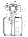
- FIG. 10 is a schematic cross-sectional view taken along the line XX in FIG.
- the seat post 38 is attached to the housing 32 so as to extend in the vertical direction inside the housing 32 and to extend upward from the upper edge of the housing 32.
- the seat post 38 is composed of a known gas spring whose length can be adjusted, and includes a cylinder 102 and a piston rod 104 inserted therein.
- the cylinder 102 is fixed to the frame 90 of the housing 32, and a lever (not shown) is provided at the lower end of the cylinder 102.
- the lever is connected to a control lever 108 provided on the upper portion of the seat post 38 by a control cable 106 (a cable and a cable holding pipe that slidably holds the cable).
- An upper opening cylindrical support member 110 is fixed to the upper end of the piston rod 104.
- a slide bar 112 extending in the left-right direction is provided slidably in the left-right direction.
- the slide bar 112 is unlocked by the slide operation knob 114 by pulling the slide operation knob 114 forward, and can slide in the left and right direction.
- the slide operation knob 114 is engaged with one of the plurality of engagement recesses 112 a formed on the front surface of the slide bar 112 to lock the slide of the slide bar 112.
- the control lever 108 is rotatably provided at the right end of the slide bar 112.
- the support member 110 is provided with a rotation mechanism 116.
- the rotation mechanism 116 is an annular ball bearing 118 provided at upper and lower two stages inside the support member 110 and a cylindrical rotation cylinder of a lower opening which is fitted inside the ball bearing 118 and rotatably supported. It is constituted by the member 120.
- a sheet support portion 122 for supporting the sheet 42 is fixed to an upper portion of the rotating cylindrical member 120. That is, the seat post 38 forms a height adjustment mechanism that couples the seat support portion 122 to the housing 32 in a height adjustable manner.
- the sheet support portion 122 is a press-formed product formed of a steel plate having a central portion fixed to the rotary cylinder member 120 and left and right side portions formed to be flush with each other at a position higher than the central portion. .
- an electric upper connector 124 for electrically connecting to the riding portion 40 is provided on the upper surface of the left side portion of the seat support portion 122.
- the rotation mechanism 116 rotatably connects the rotating cylindrical member 120 and the sheet support portion 122 to the support member 110 and the housing 32 in a plan view.
- FIG. 11 is a cross-sectional view of main parts shown along the line XX in FIG.
- a rotation lock member 128 is attached to the lower surface of the right side portion of the seat support portion 122 by a hanging bracket 126.
- the rotation lock member 128 is provided at a position facing the outer peripheral surface of the support member 110, is provided movably in the radial direction of the support member 110, and has an engagement tip 128a biased inward in the radial direction. doing.
- the engagement tip portion 128 a is capable of being engaged with and engaged with one of a plurality of recessed holes 110 a formed on the outer peripheral surface of the support member 110.
- the rotation lock member 128 disengages the engagement tip 128a from the recessed hole 110a by operating the operation grip 128b provided radially outside the support member 110 further than the bracket 126 to the outside.
- the engagement tip 128a is disengaged from the concave hole 110a of the support member 110, the sheet support portion 122 can rotate relative to the support member 110.
- the recessed holes 110 a of the present embodiment are provided at every 90 degrees in the circumferential direction on the outer peripheral surface of the support member 110, and the rotation lock member 128 is a position where the seat support portion 122 faces the front and back direction. And can be fixed at a position facing in the left-right direction.
- a gripping member 130 is attached to the upper surface of the central portion of the sheet support portion 122.
- the gripping member 130 has a rectangular base portion 132 which is long in the front-rear direction fixed to the seat supporting portion 122, and an electric component gripping portion 134 which extends upward from the base portion 132 in a tapered shape.
- the electric holding portion 134 forms a holding grip extending in the front-rear direction above the seat support portion 122 by forming a first horizontal hole 134 a penetrating in the left-right direction. Further, a second horizontal hole 134b is formed in the lower part of the electric component holding portion 134 in the front-rear direction.
- the front surface of the electrical component holding portion 134 is a curved surface that inclines rearward and upward. On the rear surface of the electric component holding portion 134, a recessed portion 134c is formed.
- FIG. 12 is a perspective view of the bottom side of the riding portion 40.
- left and right support seats 136 supported by the left and right side portions of the seat support portion 122 are formed on the bottom surface of the riding portion 40, that is, the bottom surface of the seat cushion 46.
- the left and right support seats 136 are formed on the highly rigid seat frame 50 of the seat cushion 46.
- a downward opening recess 138 is formed between the left and right support seats 136 on the bottom surface of the seat cushion 46.
- the left support seat 136 is provided with a seat-side connector 140 connected to the electrical upper connector 124 (FIG. 7).
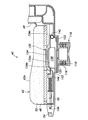
- FIG. 13 is a cross-sectional view taken along the line XIII-XIII in FIG.
- a seat side engagement pipe 142 is provided at the rear of the recess 138 and extends laterally and engages with the recess 134c of the electrical component grip 134.
- an engagement member 144 is provided which is movable in the front-rear direction and biased rearward. The rear surface of the engagement member 144 is inclined forward and downward.
- an operation member 146 which extends forward and is provided so as to be exposed on the front surface of the seat cushion 46 is connected. By operating the operation member 146 forward, the engagement member 144 moves forward. Further, when an upward load is applied to the rear surface of the engagement member 144, the engagement member 144 moves forward against the biasing force.
- the seat side engagement pipe 142 engages with the recessed portion 134c of the electrical gripping portion 134 in a state where the recess 138 receives the electrical gripping portion 134, and the engagement member 144 is the lower surface of the front end of the electrical gripping portion 134.
- the support seat 136 is supported by the seat support portion 122, and the seat side connector 140 is coupled to the electrical component unit 30 in a state of being connected to the electrical component upper connector 124 (FIG. 7). That is, the seat side engagement pipe 142 and the engagement member 144 constitute a second coupling portion detachably coupled to the seat support portion 122.
- the operation member 146 When releasing the connection of the loading unit 40 to the electrical unit 30 (separating the two members), the operation member 146 is operated forward to release the engagement of the engagement member 144 with the electrical grip unit 134. In this state, the sheet gripping portion 54 may be lifted to rotate the boarding portion 40 about the sheet side engaging pipe 142, and then the sheet gripping portion 54 and the rear portion of the seat cushion 46 may be simultaneously lifted.
- the lifting component part 40 is lowered from above with respect to the electrical component unit 30, and the electrical component gripping unit 134 is pushed into the recess 138.
- the seat side engagement pipe 142 is moved to the recessed portion 134c of the electrical holding portion 134 by moving forward while keeping the loading portion 40 inclined rearward.
- the boarding portion 40 which has been inclined, is tilted forward so as to assume the original running posture.
- the engaging member 144 is pushed forward and engaged with the front end of the electrical holding portion 134, and the riding portion 40 is coupled to the electrical portion 30.
- the electric component gripping portion 134 When the electric component gripping portion 134 is pushed into the recess 138, the electric component gripping portion 134 is tapered upward, so the recess 138 is guided by the electric component gripping portion 134, and the boarding portion 40 has a predetermined connection. Placed in position.
- the second connecting portion (the seat side engaging pipe 142 and the engaging member 144) provided at the bottom of the loading portion 40 can be easily connected to the sheet supporting portion 122.
- FIG. 14 is a perspective view of an essential part of the seat 42 in a state in which the seat surface 42 a is inclined.
- the boarding portion 40 is provided with an inclination mechanism 150 for inclining the seat surface 42 a of the seat 42 forward by inclining the cushion portion 52 with respect to the seat frame 50.
- the tilting mechanism 150 includes a left and right biasing members 152 that connect the cushion portion 52 and the seat frame 50 and bias the two in a direction away from each other.
- the biasing member 152 is constituted by a gas spring.
- the cushion portion 52 is rotatably connected to the seat frame 50 at the front end.
- Left and right seat strikers are provided at the rear of the lower surface of the cushion portion 52, and the seat frame 50 is provided with left and right seat latches 154 engageable with the corresponding seat striker.
- a seat surface control lever 156 for releasing the engagement of the seat latch 154 engaged with the seat striker is provided on the right side surface of the seat frame 50. By operating the seat control lever 156, the left and right seat latches 154 move rearward to release the engagement with the seat striker. Thus, the left and right biasing members 152 extend, and the cushion portion 52 pivots upward and forward.
- the loading unit 40 includes the tilting mechanism 150 for tilting the seating surface 42a of the seat 42 forward in the assembled state, and the seating mechanism 42a of the seat 42 can be tilted forward by the tilting mechanism 150. It is possible to easily move up from the posture of sitting at 42. In other embodiments, the tilting mechanism 150 may be configured to tilt the entire seat cushion 46.
- FIG. 15 is a perspective view of the riding portion 40 during folding.
- the seat back 48 is foldable relative to the seat cushion 46.
- the seat back 48 is coupled to the seat cushion 46 so as to be pivotable at the lower end about the pivoting axis in the left-right direction, and the upper portion from the position for boarding and the position for boarding shown in FIG. It can be pivoted forward, and can be pivoted between a folded position overlapping the seat cushion 46.
- the left and right armrests 44 are foldable relative to the seat cushion 46.
- the armrest 44 is pivotably connected to the seat back 48, and can pivot about a substantially horizontal extending elbow rest portion 160, an intermediate portion in the front-rear direction of the elbow rest portion 160, and the seat cushion 46 And a support portion 162 connected to the
- the elbow mount portion 160 has a rear portion and a front portion divided in front of a portion to which the support portion 162 is connected, and the front portion is rotatable around a pivot axis in the lateral direction with respect to the rear portion There is.
- the front portion of the elbow mount 160 is pivotable between a position for boarding shown in FIG.
- the operation box 56 is foldable relative to the armrest 44 for the right arm.
- the rear portion of the elbow rest 160 and the post 162 are folded in conjunction with the seat back 48 when folded.
- the armrest 44 is provided foldably with respect to the seat cushion 46, and the operation box 56 is provided foldably with the armrest 44 so that the armrest 44 and the operation box 56 can be compactly stored in the folded state. It is possible to provide the boarding section 40.
- the rear portion of the elbow mount 160 further extends rearward from the connecting portion with the seat back 48, and left and right stopper members 164 extending inward in the left-right direction are provided at the extension end thereof.
- the stopper member 164 abuts on the top of the back surface of the seat back 48 and restricts further rearward rotation of the seat back 48.
- the stopper member 164 interlocks with this and the armrest 44 is folded, whereby a holder 166 provided at the lower part of the back of the seat back 48 (FIG. 2, FIG. 12) Is held by As the stopper member 164 is held by the holder 166, the riding portion 40 is held in the folded state.
- the seat frame 50 of the seat cushion 46 has an L-shape which rises upward at the rear.
- the boarding unit 40 holds the standing posture with the sheet gripping unit 54 facing upward as shown in FIG. Can.
- the occupied area of the boarding unit 40 at the time of non-use in which the electric wheelchair 1 is divided and stored in a storage place or the like is reduced, and the boarding unit 40 can be stored in a narrow space. Further, the user can easily perform the lifting operation of the boarding unit 40 in the standing posture and the operation of arranging the boarding unit 40 being lifted in the standing posture.
- the sheet gripping portion 54 is located at the periphery of the folded-up loading portion 40, and particularly at the upper end on the side opposite to the rising stand 168 of the folded-up loading portion 40 when in the upright position. doing. Therefore, the passenger seat 40 with the seat back 48 folded is gripped by both hands with the seat gripping portion 54 and the opposite portion thereof, and is attached to and detached from the electrical unit 30; It is possible to carry it in a suspended manner, and the handling of the boarding portion 40 is easy.
- the folding operation of the boarding unit 40 can be easily performed by performing the folding operation first, that is, in the state of being assembled on the electric unit 30.
- the unfolding operation of the boarding portion 40 can be easily performed even after being assembled on the traveling portion 10 or even before being assembled, but in order to facilitate the operation of assembling the boarding portion 40 to the electrical component portion 30
- the mounting unit 40 may be deployed.
- the electric wheelchair 1 configured as described above has the front engagement pipe 90a, the rear latch 96, and the seat support part 122 of which the electric part 30 forms the first coupling part, and connects the traveling part 10 and the riding part 40.
- the electric wheelchair 1 can be divided into three units by removing the boarding unit 40 from the electrical unit 30 and removing the electrical unit 30 from the traveling unit 10.
- the traveling unit 10 is compact without requiring a folding operation when the electric unit 30 is removed because the vehicle body frame 12 is flat.
- the electric wheelchair 1 is divided into three units, and the electric unit 30 connecting the boarding unit 40 to the traveling unit 10 at least includes the battery 34 which is a heavy object, the variation in weight of the three units is suppressed. This facilitates handling of each unit after division.
- the seat post 38 and the rotation mechanism 116 that make up the height adjustment mechanism of the electrical unit 30 are provided, height adjustment of the boarding unit 40 with respect to the traveling unit 10 and The rotation can be made possible. And since height adjustment and rotation with respect to the traveling part 10 of the boarding part 40 become possible, expansion of the use according to a user's physique and usage condition and facilitation of getting on and off become possible.
- the present invention can be widely modified and implemented without being limited to the above embodiment.
- the electric wheelchair 1 is configured as a four-wheeled wheelchair in the above embodiment, it may be configured as a three-wheeled wheelchair, or may be configured as a wheelchair having five or more wheels.
- the electrically-wired part 30 is equipped with both the seat post 38 and the rotation mechanism 116 which make a height adjustment mechanism, you may be equipped only with one of these.
- the operation box 56 is not limited to joysticks, and may have other forms of operation components such as buttons, levers, and touch panels.
Abstract
Provided is an electric wheelchair which can be disassembled and assembled, with which units thereof can be disassembled in a compact manner with few operations, and with which units thereof after disassembly can be easily handled. An electric wheelchair 1 comprises: a travel unit 10 having a flat vehicle body frame 12, at least three wheels (front wheels 14, rear wheels 16) that are supported by the vehicle body frame 12, and an electric motor 18 for driving the wheels; an electrical unit 30 having electrical components including at least a battery 34, a first coupling unit (front-side engagement pipe 90a, rear section latch 96) that is detachably coupled to the vehicle body frame 12, and a seat support part 122; and a riding unit 40 having a seat 42 serving as a riding seat, and a second coupling unit (seat-side engagement pipe 142, engagement member 144) that is provided to a bottom part of the seat 42 and that is detachably coupled to the seat support part 122. The electric wheelchair 1 can be in an assembled state in which the travel unit 10, the electrical unit 30, and the riding unit 40 are coupled to each other, and a disassembled state in which these units are separated from each other.
Description
本開示は、分割及び組立が可能な電動車椅子に関する。
The present disclosure relates to a powered wheelchair that can be split and assembled.
電動三輪車等の電動車両として、乗用車等によって離れた目的地に運搬する際に、乗用車等に積載し易いように、分割及び組立可能なものが公知である(特許文献1)。この電動三輪車では、車体フレームが前輪を備えるフロントフレームと後輪を備えるリヤフレームとによって分割及び組立可能に構成されている。フロントフレームには、前輪に連結するステアリングシャフトとシートを取り付けるシートポストパイプとが立設されると共に、バッテリが着脱自在に搭載される。シートは、バッテリの上方に着脱自在に設けられ、ステアリングシャフトは後方に倒して折り畳めるようになっている。このように電動三輪車は、バッテリ、シート、フロントフレーム及びリヤフレームに4分割されること、また、ステアリングシャフトが折り畳めることにより、各分割ユニットの重量が軽くなり、扱い易くなる。
As an electric vehicle such as an electric three-wheeled vehicle, one that can be divided and assembled so as to be easily loaded on a passenger car or the like when transported to a distant destination by a passenger car or the like is known (Patent Document 1). In this electric three-wheeled vehicle, the vehicle body frame is configured to be split and assembled by a front frame provided with front wheels and a rear frame provided with rear wheels. On the front frame, a steering shaft connected to the front wheels and a seat post pipe for attaching a seat are erected, and a battery is detachably mounted. The seat is detachably provided above the battery, and the steering shaft is adapted to be folded rearward. As described above, the electric tricycle is divided into four parts, that is, the battery, the seat, the front frame, and the rear frame, and the folding of the steering shaft reduces the weight of each divided unit and makes it easy to handle.
また、運搬や収納を容易に行うために車両本体を前後の車輪の間で1対の構成体に分割可能とした小型電動車両において、分解作業の工程数を削減するために、1対の構成体を連結状態に保持するロック手段と、ロック手段の連結解除操作に伴って回動され、これにより横臥姿勢から構成体の傾倒を規制する起立姿勢になるスタンドとを備えたものが公知である(特許文献2)。この小型電動車両は、ユーザが連結解除操作を行うことにより、スタンドが起立姿勢になるため、スタンドの回動操作を先に行う必要がない。
In addition, in a small electric vehicle in which the vehicle main body can be divided into a pair of components between the front and rear wheels in order to facilitate transportation and storage, in order to reduce the number of steps of disassembly work, the pair of configurations It is known to have a lock means for holding the body in a connected state, and a stand which is turned along with the connection release operation of the lock means, thereby becoming a standing posture for restricting the tilting of the structure from the lying position. (Patent Document 2). In this small-sized motorized vehicle, when the user performs the connection release operation, the stand is placed in the upright posture, and it is not necessary to perform the rotation operation of the stand first.
また、上部構造と下部構造とにより組立、分割可能とされた電動式車椅子が公知である(特許文献3)。この電動式車椅子では、上部構造が、シート、背凭れ、シートレール、クロスメンバ、サブフレームを含み、シートの底部に形成される収納室内に電装品(モータやバッテリ、制御装置等)を収容しており、下部構造が、左右のメインフレーム、前輪、駆動輪、ハンドリム、サブフレーム等を含んでいる。電装品が上部構造に設けられることにより、上部構造の重量と下部構造の重量とが同程度になり、これらの扱いが容易になる。
In addition, there is known an electric wheelchair which can be assembled and divided by an upper structure and a lower structure (Patent Document 3). In this electric wheelchair, the upper structure includes a seat, a backrest, a seat rail, a cross member, and a sub frame, and electrical components (a motor, a battery, a control device, etc.) are accommodated in a storage chamber formed at the bottom of the seat. The lower structure includes left and right main frames, front wheels, drive wheels, hand rims, sub frames and the like. By providing the electrical components in the upper structure, the weight of the upper structure and the weight of the lower structure become equal to each other, and the handling thereof becomes easy.
しかしながら、特許文献1に記載の発明では、分解及び組立の作業を容易にする工夫がなされているものの、分解後に折り畳み操作が必要であるか、折り畳むことができないために分割後に各ユニットがコンパクトにならない。具体的には、コンパクト化のためにステアリングシャフトを折り畳む操作が必要である一方、シートポストパイプは折り畳むことができないため、当該部分はコンパクトにならない。また、特許文献2や特許文献3に記載の発明では、2分割にしかならないために分割後のユニットの重量が大きく、分解後の取り扱いが煩雑である。更に、これらの発明では、分割後の取り扱いや持ち運び(移動)を容易にするような工夫がなされていないため、乗用車等に積載する際に、分割された各ユニットの取り扱いや持ち運びの作業も煩雑である。
However, although the invention described in Patent Document 1 is devised to facilitate the work of disassembly and assembly, each unit becomes compact after division because a folding operation is necessary after disassembly or it can not be folded. It does not. Specifically, while the steering shaft needs to be folded for compactness, the seat post pipe can not be folded, so the portion does not become compact. Further, in the inventions described in Patent Document 2 and Patent Document 3, the weight of the unit after division is large because it is only divided into two, and handling after disassembly is complicated. Furthermore, in these inventions, since the device for handling and carrying (moving) after division is not made easy, handling of each divided unit and carrying are also complicated when loading on a passenger car etc. It is.
本発明は、このような背景に鑑み、分割及び組立が可能且つ少ない操作で各ユニットをコンパクトに分割でき、分割後の各ユニットの取り扱いを容易にできる電動車椅子を提供することを課題とする。
An object of the present invention is, in view of such background, to provide an electric wheelchair capable of dividing each unit compactly with a small number of operations that can be divided and assembled, and easy handling of each unit after division.
このような課題を解決するために、本発明のある実施形態は、電動車椅子(1)であって、扁平な車体フレーム(12)、前記車体フレーム(12)に支持された少なくとも3つの車輪(14、16)及び、車輪駆動用のモータ(18)を有する走行部(10)と、少なくともバッテリ(34)を含む電装品、前記車体フレーム(12)に着脱可能に結合する第1結合部(90a、96)及び、シート支持部(122)を有する電装部(30)と、搭乗席をなすシート(42)及び、前記シート(42)の底部に設けられ、前記シート支持部(122)に着脱可能に結合する第2結合部(142、144)を有する搭乗部(40)とを備え、前記走行部(10)、前記電装部(30)及び前記搭乗部(40)が互いに結合した組立状態と、これらが互いに分離した分割状態とを取り得る。
In order to solve such problems, an embodiment of the present invention is an electric wheelchair (1), which includes a flat body frame (12) and at least three wheels supported by the body frame (12) 14, 16), a traveling part (10) having a motor (18) for driving a wheel, an electrical component including at least a battery (34), a first coupling part detachably coupled to the vehicle body frame (12) 90a, 96), an electric part (30) having a seat support part (122), a seat (42) forming a passenger seat, and a bottom part of the seat (42), the seat support part (122) And an riding portion (40) having a second coupling portion (142, 144) detachably coupled, wherein the traveling portion (10), the electric component (30) and the riding portion (40) are mutually connected. State, Can take a divided state these are separated from each other.
この構成によれば、電装部が第1結合部及びシート支持部を有し、走行部と搭乗部とを連結するため、搭乗部を電装部から取り外し、電装部を走行部から取り外すことにより、電動車椅子を3つのユニットに分割できる。走行部は、車体フレームが扁平であるため、電装部が取り外されると、折り畳み操作を要することなくコンパクトになる。また、電動車椅子が3つのユニットに分割され、搭乗部を走行部に連結する電装部が重量物であるバッテリを少なくとも含む電装品を有しているため、3つのユニットの重量のばらつきが抑制される。これにより、分割後の各ユニットの取り扱いが容易になる。
According to this configuration, the electrical component unit has the first joint component and the seat support component, and the carrying component unit is removed from the electrical component unit and the electrical component unit is removed from the traveling component in order to connect the traveling component and the riding component. The electric wheelchair can be divided into three units. Since the traveling part has a flat body frame, it becomes compact without requiring a folding operation when the electric part is removed. In addition, since the electric wheelchair is divided into three units, and the electric unit connecting the boarding unit to the traveling unit has an electric component including at least a heavy battery, the variation in weight of the three units is suppressed. Ru. This facilitates handling of each unit after division.
上記構成において、前記電装部(30)は、前記シート支持部(122)を前記第1結合部(90a、96)に対して高さ調整可能に連結する高さ調整機構(38)及び、平面視において前記シート支持部(122)を前記第1結合部(90a、96)に対して回転可能に連結する回転機構(116)の少なくとも一方を更に備えるとよい。
In the above-mentioned configuration, the electric component unit (30) connects the sheet support part (122) to the first coupling part (90a, 96) such that the height adjustment mechanism (38) can adjust the height, and It is preferable to further include at least one of a rotation mechanism (116) that rotatably connects the sheet support portion (122) with respect to the first coupling portion (90a, 96) as viewed.
この構成によれば、搭乗部を重量化することなく、搭乗部の走行部に対する高さ調整及び回転の少なくとも一方を可能にすることができる。搭乗部の走行部に対する高さ調整及び回転の少なくとも一方が可能になることにより、ユーザの体格や使用状況に合わせた用途の拡大や乗り降りの容易化が可能になる。
According to this configuration, it is possible to enable at least one of height adjustment and rotation of the riding portion relative to the traveling portion without increasing the weight of the riding portion. By at least one of height adjustment and rotation with respect to the traveling part of the boarding part being enabled, it is possible to expand the application according to the user's physique and usage conditions and to facilitate the getting on and off.
上記構成において、好ましくは、前記電装部(30)は、前記電装部(30)が前記走行部(10)に組み付けられた状態において、上部にて上方に向けて先細の形状をなす第1把持部(134)を更に備え、前記第2結合部(142、144)には、前記組立状態において下向きに開口し、前記第1把持部(134)を受容する凹部(138)が形成されている。
In the above configuration, preferably, the electrical component unit (30) has a first grip that is tapered upward at an upper portion in a state where the electrical component unit (30) is assembled to the traveling unit (10). The second joint (142, 144) is formed with a recess (138) which opens downward in the assembled state and receives the first grip (134). .
この構成によれば、電装部が第1把持部を備えることにより、電装部の走行部への着脱が容易に行える。また、第1把持部が上方に向けて先細の形状をなし、搭乗部の第2結合部に第1把持部を受容する下向きに開口の凹部が形成されることにより、搭乗部を電装部に取り付ける際に凹部が第1把持部にガイドされ、搭乗部が所定の結合位置に配置される。これにより、搭乗部の底部に設けられた第2結合部のシート支持部への結合操作が容易に行える。
According to this configuration, by providing the first holding unit, the electrical component unit can be easily attached to and detached from the traveling unit of the electrical component unit. In addition, by forming the concave portion of the opening downward to receive the first gripping portion at the second coupling portion of the riding portion, the first gripping portion has a tapered shape toward the upper side, so that the riding portion can be provided as an electrical component. At the time of attachment, the recess is guided by the first gripping portion, and the riding portion is disposed at the predetermined coupling position. Thus, the operation of connecting the second connecting portion provided at the bottom of the loading portion to the seat supporting portion can be easily performed.
上記構成において、好ましくは、前記走行部(10)は、前記分割状態において、ユーザにより把持されることにより、2つの車輪(16)を接地させ且つ少なくとも1つの車輪(14)を浮かせた傾斜姿勢を当該走行部(10)にもたらす第2把持部(84)を更に備える。
In the above configuration, preferably, the traveling unit (10) is in an inclined posture in which the two wheels (16) are grounded and the at least one wheel (14) is floated by being held by the user in the divided state. And a second gripping portion (84) for bringing the traveling portion (10) into question.
この構成によれば、ユーザは第2把持部を把持し、2つの車輪を接地させた傾斜姿勢の状態で走行部を運搬することができ、取り扱いが容易になる。
According to this configuration, the user can grip the second grip portion, can transport the traveling portion in an inclined posture in which the two wheels are grounded, and handling becomes easy.
上記構成において、好ましくは、前記走行部(10)は、前記組立状態において、電動車椅子(1)の後方への傾動時に接地することによって電動車椅子(1)の転倒を防止する転倒防止部材(60)を更に備え、当該転倒防止部材(60)は、電動車椅子(1)の転倒を防止するための転倒防止位置と、前記分割状態において、当該走行部(10)が前記2つの車輪(16)を接地させた状態で起立する起立姿勢を保持するように接地する、前記転倒防止位置と異なるスタンド位置とを取り得るように可動に構成されている。
In the above configuration, preferably, the traveling unit (10) is a fall prevention member (60 for preventing the electric wheelchair (1) from overturning by grounding when the electric wheelchair (1) is tilted rearward in the assembled state). In which the traveling portion (10) is the two wheels (16) in the divided state, and the fall prevention member (60) is the fall prevention position for preventing the fall of the electric wheelchair (1). Is configured to be movable so as to take a stand position different from the overturn preventing position and to ground so as to hold a standing posture standing up in a grounded state.
この構成によれば、転倒防止部材を転倒防止位置からスタンド位置に変位させることにより、走行部を起立姿勢に保持できる。これにより、非使用時における走行部の占有面積を小さくでき、狭いスペースに走行部を収納することができる。
According to this configuration, the traveling portion can be held in the standing posture by displacing the overturn preventing member from the overturn preventing position to the stand position. Thereby, the occupied area of the traveling part at the time of non-use can be made small, and the traveling part can be stored in a narrow space.
上記構成において、好ましくは、前記走行部(10)は、少なくとも1つの全方向移動車輪(14)を備える。
In the above configuration, preferably, the traveling unit (10) includes at least one omnidirectional moving wheel (14).
この構成によれば、操舵輪を操舵するためのハンドルや操舵機構を走行部に設ける必要がないため、走行部をコンパクトに構成することができる。
According to this configuration, there is no need to provide a steering wheel and a steering mechanism for steering the steered wheels in the traveling unit, so that the traveling unit can be made compact.
上記構成において、好ましくは、前記シート(42)は、前記電装部(30)によって支持されるシートクッション(46)及び当該シートクッション(46)に対して折り畳み可能に設けられたシートバック(48)を備え、前記搭乗部(40)は、前記シートバック(48)が折り畳まれた状態において周縁部に配置された第3把持部(54)を更に備える。
In the above configuration, preferably, the seat (42) is a seat cushion (46) supported by the electric part (30) and a seat back (48) provided foldably with respect to the seat cushion (46). And the boarding portion (40) further includes a third grip portion (54) disposed at the periphery in a state where the seat back (48) is folded.
この構成によれば、シートバックが折り畳まれた状態の搭乗部を、第3把持部とその反対側の部分とを両手で把持して電装部に着脱することや、第3把持部を把持して吊り下げるようにして運搬することが可能になり、搭乗部の取り扱いが容易になる。
According to this configuration, the passenger compartment in a state where the seat back is folded is gripped with both hands by the third gripping part and the opposite part thereof, and is attached to and detached from the electric part, or the third gripping part is gripped It becomes possible to carry it by suspending it and handle the boarding part easier.
上記構成において、好ましくは、前記搭乗部(40)は、前記シートバック(48)が折り畳まれた状態において、当該搭乗部(40)が前記シート(42)を縦にした起立姿勢に保持されるように接地する起立スタンド(168)を更に備え、前記第3把持部(54)は、前記シートバック(48)が折り畳まれた状態において、前記搭乗部(40)における前記起立スタンド(168)と相反する側に設けられている。
In the above configuration, preferably, the boarding portion (40) is held in the upright posture in which the sheeting portion (40) is in the vertical position, with the seat back (48) folded. And the third gripping portion (54), with the seat back (48) folded, with the standing stand (168) in the riding portion (40). It is provided on the opposite side.
この構成によれば、起立スタンドにより、シートバックが折り畳まれた状態の搭乗部を第3把持部が上になる起立姿勢の状態に保持できる。これにより、電動車椅子を分割した状態で保管場所等に収納する非使用時の搭乗部の占有面積を小さくでき、狭いスペースに搭乗部を収納できる。また、起立姿勢にある搭乗部を持ち上げる動作や、持ち上げている搭乗部を起立姿勢に配置する動作をユーザが簡単に行える。
According to this configuration, the standing stand can hold the riding portion in a state in which the seatback is folded in the standing posture in which the third grip portion is up. This makes it possible to reduce the occupied area of the boarding portion when not in use, in which the electric wheelchair is divided and stored in a storage place or the like, and the boarding portion can be stored in a narrow space. In addition, the user can easily perform an operation of lifting the boarding portion in the standing posture and an operation of arranging the boarding portion being lifted in the standing posture.
上記構成において、好ましくは、前記搭乗部(40)は、前記シートクッション(46)に対して折り畳み可能に設けられた肘掛け(44)と、前記肘掛け(44)に折り畳み可能に設けられ、駆動車輪を操作するための操作部(56)とを更に備える。
In the above configuration, preferably, the riding portion (40) is foldably provided on an armrest (44) foldably provided relative to the seat cushion (46) and the armrest (44), and the driving wheel And an operation unit (56) for operating the
この構成によれば、折り畳み状態においてコンパクトに収納される肘掛け及び操作部を搭乗部に設けることができる。
According to this configuration, the mounting portion can be provided with the armrest and the operation portion that are compactly stored in the folded state.
上記構成において、好ましくは、前記搭乗部(40)は、前記組立状態において、前記シート(42)の座面(42a)を前方に傾斜させる傾斜機構(150)を更に備える。
In the above configuration, preferably, the riding portion (40) further includes an inclination mechanism (150) for inclining the seat surface (42a) of the seat (42) forward in the assembled state.
この構成によれば、傾斜機構によってシートを前方に傾動させることにより、シートに着席した姿勢から立ち上がる動作を容易にすることができる。
According to this configuration, by tilting the seat forward by the tilting mechanism, it is possible to facilitate the operation of standing up from the posture of sitting on the seat.
このように本発明によれば、分割及び組立が可能且つ少ない操作で各ユニットをコンパクトに分割でき、分割後の各ユニットの取り扱いを容易にできる電動車椅子を提供することができる。
As described above, according to the present invention, it is possible to provide an electric wheelchair that can be divided and assembled, can be divided into compact units with less operation, and can easily handle the divided units.
以下、図面を参照して、本発明の電動車椅子1の実施形態について詳細に説明する。
Hereinafter, an embodiment of the electric wheelchair 1 of the present invention will be described in detail with reference to the drawings.
図1は実施形態に係る電動車椅子1の斜視図であり、図2は電動車椅子1の背面図である。図1及び図2に示されるように、電動車椅子1は、扁平な略矩形の車体フレーム12と、車体フレーム12によって支持された左右の前輪14及び左右の後輪16とを有する走行部10を備えた4輪車椅子である。前輪14及び後輪16の大きさ(外径)は概ね同程度とされており、これにより、扁平な車体フレーム12は地面に概ね平行に延在している。
FIG. 1 is a perspective view of the electric wheelchair 1 according to the embodiment, and FIG. 2 is a rear view of the electric wheelchair 1. As shown in FIGS. 1 and 2, the electric wheelchair 1 has a traveling portion 10 having a flat, substantially rectangular body frame 12 and left and right front wheels 14 and left and right rear wheels 16 supported by the body frame 12. It is a four wheel wheelchair equipped. The sizes (outside diameters) of the front wheel 14 and the rear wheel 16 are approximately the same, whereby the flat body frame 12 extends substantially parallel to the ground.
左右の後輪16には、車幅方向内側に配置された車輪駆動用の左右の電動モータ18が直結されている。左右の電動モータ18は、回転軸を左右方向に延在させた姿勢で同軸上に配置され、車体フレーム12に取り付けられた左右の後輪ブラケット20により支持されている。
The left and right electric motors 18 for driving the wheels disposed on the inner side in the vehicle width direction are directly connected to the left and right rear wheels 16. The left and right electric motors 18 are coaxially disposed in a posture in which the rotation axis extends in the left-right direction, and are supported by the left and right rear wheel brackets 20 attached to the vehicle body frame 12.
左右の前輪14は、車体フレーム12に取り付けられた左右の前輪ブラケット22により、左右方向に延びる車軸回りに回転可能に支持されている。各前輪14は、前輪ブラケット22により車軸回りに回転可能に車体に取り付けられた回転部材24と、回転部材24の外周部にて接線方向に延びる回転軸回りに回転可能に設けられた複数のフリーローラ26とを備えたオムニホイールである。前輪14は、回転部材24が回転することによって床面上を車軸に直交する方向に移動し、フリーローラ26が回転することによって床面上を車軸方向に移動する。即ち、前輪14は、両回転による移動量の比率に応じて床面上を全方向に移動可能な全方向車輪である。
The left and right front wheels 14 are rotatably supported around an axle extending in the left-right direction by the left and right front wheel brackets 22 attached to the vehicle body frame 12. Each front wheel 14 is provided with a rotating member 24 attached to the vehicle body so as to be rotatable about an axle by a front wheel bracket 22, and a plurality of freewheels rotatably provided about an axis of rotation extending tangentially on the outer peripheral portion of the rotating member 24. It is an omni wheel provided with a roller 26. The front wheel 14 moves on the floor surface in a direction perpendicular to the axle by rotation of the rotating member 24 and moves on the floor surface in the direction of the axle by rotation of the free roller 26. That is, the front wheel 14 is an omnidirectional wheel capable of moving on the floor surface in all directions in accordance with the ratio of the amount of movement by both rotations.
左右の電動モータ18が左右の後輪16を同方向に同速度で回転駆動することにより、走行部10は直進し、左右の電動モータ18が左右の後輪16を同方向に異なる速度で回転駆動することにより、走行部10は旋回する。また、左右の電動モータ18が左右の後輪16を逆方向に回転駆動することにより、走行部10は回転(自転)する。このように走行部10は、全方向移動車輪を備えるため、操舵輪を操舵するためのハンドルや操舵機構を備える必要がなく、コンパクトに構成することが可能になっている。
The left and right electric motors 18 rotationally drive the left and right rear wheels 16 in the same direction at the same speed, whereby the traveling unit 10 goes straight and the left and right electric motors 18 rotate the left and right rear wheels 16 in the same direction at different speeds. By driving, the traveling unit 10 turns. In addition, when the left and right electric motors 18 rotationally drive the left and right rear wheels 16 in the reverse direction, the traveling unit 10 rotates (rotationally). As described above, since the traveling unit 10 includes the omnidirectionally moving wheels, it is not necessary to include a steering wheel and a steering mechanism for steering the steered wheels, and the traveling unit 10 can be configured compactly.
車体フレーム12の後部には、略直方体形状の筐体32と、筐体32に収容されたバッテリ34や電子制御装置36等の電装品と、シートポスト38とを有する電装部30が設けられている。
At the rear of the vehicle body frame 12, there is provided an electrical unit 30 having a substantially rectangular parallelepiped casing 32, electrical components such as a battery 34 and an electronic control unit 36 accommodated in the casing 32, and a seat post 38. There is.
電装部30の上には、搭乗席をなすシート42と、シート42に一体に取り付けられた左右の肘掛け44とを備えた搭乗部40が設けられている。シート42は、シートクッション46と、シートクッション46に対して折り畳み可能に設けられたシートバック48とを備えている。シートクッション46は、下部に設けられた剛性の高いシートフレーム50と、シートフレーム50の上に傾動可能に設けられ、シート42の座面42aを形成するクッション部52とを備えている。シートフレーム50の前面には、左右方向に延在するシート把持部54が設けられている。右腕用の肘掛け44の前端には、駆動車輪である後輪16を操作するための操作部である操作ボックス56が設けられている。操作ボックス56は、上方に延出するジョイスティック56aを備えている。左腕用の肘掛け44の前端には、操作ボックス56が設けられる代わりに上方に延出する運転用グリップ58が設けられている。
On the electrical component unit 30, there is provided a boarding unit 40 including a seat 42 serving as a passenger seat and left and right armrests 44 integrally attached to the seat 42. The seat 42 includes a seat cushion 46 and a seat back 48 provided foldably with respect to the seat cushion 46. The seat cushion 46 includes a highly rigid seat frame 50 provided at the lower part, and a cushion portion 52 provided on the seat frame 50 so as to be tiltable and forming a seat surface 42 a of the seat 42. A sheet gripping portion 54 extending in the left-right direction is provided on the front surface of the seat frame 50. At the front end of the right arm armrest 44, an operation box 56 which is an operation unit for operating the rear wheel 16 which is a driving wheel is provided. The operation box 56 includes a joystick 56 a extending upward. At the front end of the armrest 44 for the left arm, a driving grip 58 extending upward instead of the operation box 56 is provided.
図3の分解斜視図に示すように、電動車椅子1は、走行部10、電装部30及び搭乗部40が互いに分離した3つのユニットに分割された分割状態を取り得るように構成されている。そして、電動車椅子1は、これら3つのユニットが互いに結合されることにより、図1に示す組立状態となる。各ユニットの結合構造の詳細については後述する。
As shown in the exploded perspective view of FIG. 3, the electric wheelchair 1 is configured to be able to be divided into three divided units separated from each other by the traveling unit 10, the electrical unit 30 and the boarding unit 40. And electric wheelchair 1 will be in the assembling state shown in Drawing 1 by connecting these three units mutually. Details of the connection structure of each unit will be described later.
図4は、分解状態における走行部10の要部斜視図である。図2及び図4に示すように、車体フレーム12の後部には、電動車椅子1の後方への転倒を防止するための転倒防止部材60が設けられている。転倒防止部材60は、車体フレーム12から後方に延出する左右のアーム62と、左右のアーム62の前端を連結する基端側シャフト64と、左右のアーム62の遊端に支持され、左右方向に延在する遊端側シャフト66と、遊端側シャフト66の左右の両端に回転自在に設けられた左右のローラ68とを備えている。左右のローラ68は、電動車椅子1が4輪(14、16)を接地させた走行可能状態にある時に後輪16の接地部よりも高い位置に配置されており、電動車椅子1が前輪14を浮かせるように後方に傾動した時に接地する。
FIG. 4 is a perspective view of an essential part of the traveling unit 10 in the disassembled state. As shown in FIGS. 2 and 4, at the rear of the vehicle body frame 12, a fall prevention member 60 for preventing a fall to the rear of the electric wheelchair 1 is provided. The overturn preventing member 60 is supported by left and right arms 62 extending rearward from the vehicle body frame 12, a proximal shaft 64 connecting front ends of the left and right arms 62, and free ends of the left and right arms 62. , And left and right rollers 68 rotatably provided at both left and right ends of the free end side shaft 66. The left and right rollers 68 are disposed at a position higher than the contact portion of the rear wheel 16 when the electric wheelchair 1 is in the travelable state with four wheels (14, 16) grounded, and the electric wheelchair 1 has the front wheel 14 Contact the ground when tilting backwards to float.
図4に示すように、車体フレーム12の上面には、電装部30を支持するために電装部支持構造70が設けられている。電装部支持構造70は、前側に設けられた左右の係止部材72と、後側に設けられた左右のストライカ74とを備えている。各係止部材72は、車体フレーム12に固定され、上方に向けて延出し、上部にて後方に延出している。各ストライカ74は、車体フレーム12の上方にて前後方向に延在するように車体フレーム12に固定された支持バーである。
As shown in FIG. 4, on the upper surface of the vehicle body frame 12, an electrical part support structure 70 is provided to support the electrical part 30. The electrical part supporting structure 70 includes left and right locking members 72 provided on the front side, and left and right strikers 74 provided on the rear side. Each locking member 72 is fixed to the vehicle body frame 12, extends upward, and extends rearward at the top. Each striker 74 is a support bar fixed to the vehicle body frame 12 so as to extend in the front-rear direction above the vehicle body frame 12.
車体フレーム12の上面の電装部30が載置される部分には、貫通孔12aが形成されると共に、貫通孔12aの左右の両側に、電装部30との電気的な接続を行うための車体側コネクタ76が設けられている。また、車体フレーム12の上面の電装部30が載置される部分の左側方には、電装部30の位置を決めるための位置決め部材78が設けられている。
A through hole 12a is formed in a portion of the upper surface of the vehicle body frame 12 on which the electrical component unit 30 is mounted, and a vehicle body for electrically connecting with the electrical component unit 30 on both left and right sides of the through hole 12a. A side connector 76 is provided. A positioning member 78 for determining the position of the electrical unit 30 is provided on the left side of the portion of the upper surface of the vehicle body frame 12 on which the electrical unit 30 is mounted.
車体フレーム12の上面後部には、転倒防止部材60の基端側シャフト64を回動自在に保持する左右の保持ブラケット80が固定されている。各保持ブラケット80には、左右方向に移動可能に設けられ、対応するアーム62の回動位置を固定するための操作ノブ82が設けられている。操作ノブ82は対応するアーム62に向けて付勢されており、対応するアーム62に形成された複数の係合孔62a(図5)の1つに係合することによってアーム62の回動を規制する。操作ノブ82が操作されて係合孔62aから離脱することにより、転倒防止部材60は基端側シャフト64回りに可動になる。
Left and right holding brackets 80 for rotatably holding the base end side shaft 64 of the overturn preventing member 60 are fixed to the upper surface rear portion of the vehicle body frame 12. Each holding bracket 80 is provided movably in the left-right direction, and is provided with an operation knob 82 for fixing the rotational position of the corresponding arm 62. The operation knob 82 is biased toward the corresponding arm 62, and pivots the arm 62 by engaging one of a plurality of engagement holes 62a (FIG. 5) formed in the corresponding arm 62. regulate. When the operation knob 82 is operated and disengaged from the engagement hole 62 a, the overturn preventing member 60 becomes movable around the proximal shaft 64.
係合孔62aは、転倒防止部材60が図4に示される位置(即ち、電動車椅子1の転倒を防止するための転倒防止位置)にある時に操作ノブ82が係合する位置と、図5に示すように、転倒防止部材60が遊端側のローラ68を転倒防止位置から上方に跳ね上げた状態の時に操作ノブ82が係合する位置とに形成されている。転倒防止部材60がローラ68を跳ね上げた状態では、図6に示すように、走行部10は左右の後輪16及び左右のローラ68の4点支持により自立可能になる。言い換えれば、転倒防止部材60は、上記の転倒防止位置と、分割状態の走行部10が2つの後輪16を接地させた状態で起立する起立姿勢を保持するように接地するスタンド位置とを取り得るように設けられている。このように、転倒防止部材60を転倒防止位置からスタンド位置に変位させることにより、走行部10は起立姿勢に保持可能である。これにより、非使用時における走行部10の占有面積が小さくなり、狭いスペースに走行部10を収納することが可能になる。
The engagement hole 62a is a position where the operation knob 82 engages when the overturn preventing member 60 is in the position shown in FIG. 4 (ie, the overturn preventing position for preventing overturning of the electric wheelchair 1); As shown, the overturn preventing member 60 is formed at a position where the operation knob 82 engages when the roller 68 on the free end side is lifted up from the overturn preventing position. In the state where the overturn preventing member 60 has flipped up the roller 68, as shown in FIG. 6, the traveling portion 10 can stand by four points of support of the left and right rear wheels 16 and the left and right rollers 68. In other words, the overturn preventing member 60 takes the above-mentioned overturn preventing position and the stand position at which the traveling portion 10 in the division state is in contact with the stand so as to hold the standing posture in which the two rear wheels 16 stand. It is provided to earn. As described above, by displacing the overturn preventing member 60 from the overturn preventing position to the stand position, the traveling unit 10 can be held in the upright posture. As a result, the occupied area of the traveling unit 10 when not in use becomes smaller, and the traveling unit 10 can be stored in a narrow space.
車体フレーム12の前端、即ち走行部10が起立姿勢にある時の車体フレーム12の上端には、使用者による把持に供されるフレーム把持部84が形成されている。フレーム把持部84は、車体フレーム12に形成された貫通スロットによってグリップの態様で車体フレーム12に一体形成されている。使用者は、フレーム把持部84を把持し、車体フレーム12を前方(起立姿勢において車体フレーム12の底面が向く方向)に倒して後輪16のみを接地させた状態にして、走行部10を手動走行の態様で運搬することができる。即ち、フレーム把持部84は、ユーザにより把持されることにより、2つの後輪16を接地させ且つ2つの前輪14を浮かせた傾斜姿勢を走行部10にもたらす。これにより、走行部10の取り扱いが容易になっている。
At the front end of the vehicle body frame 12, that is, at the upper end of the vehicle body frame 12 when the traveling unit 10 is in the upright posture, a frame gripping unit 84 to be gripped by a user is formed. The frame grip portion 84 is integrally formed with the vehicle body frame 12 in the form of a grip by a through slot formed in the vehicle body frame 12. The user grips the frame grip portion 84 and turns the vehicle body frame 12 forward (in the standing posture, in the direction in which the bottom surface of the vehicle body frame 12 faces) so that only the rear wheel 16 is in contact with the ground. It can be transported in a traveling manner. That is, the frame gripping portion 84 brings the two rear wheels 16 into contact with the ground and brings the two front wheels 14 into the inclined posture in the traveling portion 10 by being gripped by the user. Thereby, the handling of the traveling unit 10 is facilitated.
また、起立姿勢にある車体フレーム12の上下方向の中間部(走行姿勢における重心の前後方向位置に対応する位置)における左右の側縁部にも、左右の側部把持部86が形成されている。これにより、走行部10を自動車等の運搬車両に対して積み下ろしする際に、使用者が両手で側部把持部86を把持して持ち上げ易いようになっている。更に、走行姿勢にある車体フレーム12の後端(起立姿勢における下端)にも、後部保持部88(図5)が形成されている。
Left and right side grips 86 are also formed on the left and right side edge portions of the vertical middle portion of the vehicle body frame 12 in the standing posture (position corresponding to the longitudinal position of the center of gravity in the traveling posture). . As a result, when loading and unloading the traveling unit 10 with respect to a transport vehicle such as a car, the user can easily hold and hold the side grip 86 with both hands. Further, a rear holding portion 88 (FIG. 5) is also formed at the rear end (the lower end in the standing posture) of the vehicle body frame 12 in the traveling posture.
図7は電装部30の斜視図であり、図8は走行部10と電装部30との前側結合部の斜視図である。図7及び図8に示すように、電装部30の筐体32は、略直方体形状の辺に沿って設けられたフレーム90と、フレーム90の外側に設けられたカバー92とを有している。なお、図8においてはカバー92を想像線で示している。フレーム90は断面矩形状の鋼製の角パイプや断面円形状の鋼製の丸パイプを溶接により互いに接合して形成されている。フレーム90は、下部前縁にて左右に延在し、左右の係止部材72に対して後方からのスライドによって係合する丸パイプからなる前側係合パイプ90aを備えている。
FIG. 7 is a perspective view of the electrical component unit 30, and FIG. 8 is a perspective view of the front joint of the traveling unit 10 and the electrical component unit 30. As shown in FIG. As shown in FIGS. 7 and 8, the housing 32 of the electrical component unit 30 has a frame 90 provided along the substantially rectangular parallelepiped side and a cover 92 provided outside the frame 90. . In FIG. 8, the cover 92 is shown by an imaginary line. The frame 90 is formed by welding together a square pipe made of steel having a rectangular cross section and a round pipe made of steel having a circular cross section. The frame 90 is provided with a front engagement pipe 90a which is a round pipe which extends left and right at the lower front edge and engages with the left and right locking members 72 by sliding from the rear.
図9は走行部10と電装部30との後側結合部の斜視図である。なお、図9においてはカバー92を省略しており、電装部30の内部を透視したように示している。電装部30の筐体32の後部には、前側係合パイプ90aと協働して電装部30を車体フレーム12に着脱可能に結合するための後部結合構造94が一体に設けられている。後部結合構造94は、前側係合パイプ90aが左右の係止部材72に係合した状態において左右のストライカ74に対応する位置に設けられ、対応するストライカ74に着脱自在に係合する左右の後部ラッチ96を備えている。各後部ラッチ96は、ストライカ74に係合する係合位置と、ストライカ74に係合しない解除位置との間を回動可能に設けられると共に、係合位置に向けて付勢されている。筐体32には、左右の後部ラッチ96を係合位置から解除位置に操作するための操作ハンドル98が上下動可能に設けられている。操作ハンドル98は、ワイヤー100によって左右の後部ラッチ96に連結されており、上方に操作されることによって後部ラッチ96を係合位置から解除位置に回動させる。
FIG. 9 is a perspective view of the rear side coupling portion between the traveling portion 10 and the electrical component portion 30. FIG. In FIG. 9, the cover 92 is omitted, and the inside of the electrical component unit 30 is shown as seen through. At the rear of the housing 32 of the electrical unit 30, a rear coupling structure 94 for detachably coupling the electrical unit 30 to the vehicle body frame 12 in cooperation with the front engagement pipe 90a is integrally provided. The rear joint structure 94 is provided at a position corresponding to the left and right strikers 74 in a state where the front engagement pipe 90a is engaged with the left and right locking members 72, and the left and right rears detachably engage with the corresponding striker 74. A latch 96 is provided. Each rear latch 96 is rotatably provided between an engagement position engaging with the striker 74 and a release position not engaging with the striker 74, and is biased toward the engagement position. The housing 32 is provided with an operation handle 98 for vertically moving the left and right rear latches 96 from the engaged position to the released position. The operating handle 98 is connected to the left and right rear latches 96 by the wire 100, and when operated upward, causes the rear latch 96 to pivot from the engaged position to the released position.
前側係合パイプ90a及び後部ラッチ96により、車体フレーム12に着脱可能に結合する第1結合部が構成される。
The front engagement pipe 90 a and the rear latch 96 constitute a first coupling portion detachably coupled to the vehicle body frame 12.
筐体32の内部には、前側係合パイプ90a及び後部結合構造94によって走行部10に結合した状態において、車体側コネクタ76(図4)に接続される図示しない電装下側コネクタが固定されている。
An electrical lower connector (not shown) connected to the vehicle body connector 76 (FIG. 4) is fixed inside the housing 32 in a state of being coupled to the traveling portion 10 by the front engagement pipe 90a and the rear coupling structure 94. There is.
図10は、図7中のX-X線に沿って示す概略断面図である。図10に示すように、シートポスト38は、筐体32の内部を上下方向に延在して筐体32の上縁から上方に延出するように筐体32に取り付けられている。シートポスト38は、長さ調整が可能な公知のガススプリングから構成され、シリンダ102とこれに嵌挿されたピストンロッド104とを備えている。シリンダ102は筐体32のフレーム90に固定されており、シリンダ102の下端には図示しないレバーが設けられている。このレバーは、操作ケーブル106(ケーブル及びこれを摺動可能に保持するケーブル保持パイプ)によってシートポスト38の上部に設けられた操作レバー108に連結されている。操作レバー108が操作されることにより、ピストンロッド104に対するロックが解除され、シリンダ102内に封入されたガスによってピストンロッド104が伸長方向に押し出される。また、操作レバー108が操作されている間に大きな圧縮荷重がピストンロッド104に加わると、ピストンロッド104は短縮方向に押し戻される。
FIG. 10 is a schematic cross-sectional view taken along the line XX in FIG. As shown in FIG. 10, the seat post 38 is attached to the housing 32 so as to extend in the vertical direction inside the housing 32 and to extend upward from the upper edge of the housing 32. The seat post 38 is composed of a known gas spring whose length can be adjusted, and includes a cylinder 102 and a piston rod 104 inserted therein. The cylinder 102 is fixed to the frame 90 of the housing 32, and a lever (not shown) is provided at the lower end of the cylinder 102. The lever is connected to a control lever 108 provided on the upper portion of the seat post 38 by a control cable 106 (a cable and a cable holding pipe that slidably holds the cable). By operating the operation lever 108, the lock on the piston rod 104 is released, and the gas enclosed in the cylinder 102 pushes the piston rod 104 in the extension direction. Further, when a large compressive load is applied to the piston rod 104 while the control lever 108 is operated, the piston rod 104 is pushed back in the shortening direction.
ピストンロッド104の上端には、上方開口の筒状の支持部材110が固定されている。支持部材110の前側には左右方向に延在するスライドバー112が左右にスライド可能に設けられている。スライドバー112は、図7に示すように、スライド操作ノブ114を前方に引くことによってスライド操作ノブ114によるロックが解除され、左右方向にスライド可能になる。スライドバー112の前面に形成された複数の係合凹部112aの1つにスライド操作ノブ114が係合することにより、スライドバー112のスライドがロックされる。スライドバー112の右端に上記の操作レバー108が回動操作可能に設けられている。
An upper opening cylindrical support member 110 is fixed to the upper end of the piston rod 104. On the front side of the support member 110, a slide bar 112 extending in the left-right direction is provided slidably in the left-right direction. As shown in FIG. 7, the slide bar 112 is unlocked by the slide operation knob 114 by pulling the slide operation knob 114 forward, and can slide in the left and right direction. The slide operation knob 114 is engaged with one of the plurality of engagement recesses 112 a formed on the front surface of the slide bar 112 to lock the slide of the slide bar 112. The control lever 108 is rotatably provided at the right end of the slide bar 112.
図10に示すように、支持部材110には、回転機構116が設けられている。回転機構116は、支持部材110の内部に上下2段に設けられた円環状のボールベアリング118と、ボールベアリング118の内側に嵌着し、回転可能に支持された下方開口の筒状の回転筒部材120とにより構成されている。回転筒部材120の上部には、シート42を支持するためのシート支持部122が固定されている。即ち、シートポスト38は、シート支持部122を筐体32に対して高さ調整可能に連結する高さ調整機構をなしている。
As shown in FIG. 10, the support member 110 is provided with a rotation mechanism 116. The rotation mechanism 116 is an annular ball bearing 118 provided at upper and lower two stages inside the support member 110 and a cylindrical rotation cylinder of a lower opening which is fitted inside the ball bearing 118 and rotatably supported. It is constituted by the member 120. A sheet support portion 122 for supporting the sheet 42 is fixed to an upper portion of the rotating cylindrical member 120. That is, the seat post 38 forms a height adjustment mechanism that couples the seat support portion 122 to the housing 32 in a height adjustable manner.
シート支持部122は、回転筒部材120に固定される中央部と、中央部に比べて高い位置に同一平面をなすように形成された左右の側部とを有する鋼板からなるプレス成形品である。シート支持部122の左側部の上面には、搭乗部40との電気的な接続を行うための電装上側コネクタ124が設けられている。回転機構116は、平面視において回転筒部材120やシート支持部122を支持部材110や筐体32に対して回転可能に連結している。
The sheet support portion 122 is a press-formed product formed of a steel plate having a central portion fixed to the rotary cylinder member 120 and left and right side portions formed to be flush with each other at a position higher than the central portion. . On the upper surface of the left side portion of the seat support portion 122, an electric upper connector 124 for electrically connecting to the riding portion 40 is provided. The rotation mechanism 116 rotatably connects the rotating cylindrical member 120 and the sheet support portion 122 to the support member 110 and the housing 32 in a plan view.
図11は、図7中のX-X線に沿って示す要部断面図である。シート支持部122の右側部の下面には、垂下するブラケット126によって回転ロック部材128が取り付けられている。回転ロック部材128は、支持部材110の外周面に対峙する位置に設けられており、支持部材110の径方向に移動可能に設けられ、径方向内側に付勢された係合先端部128aを有している。係合先端部128aは、支持部材110の外周面に形成された複数の凹孔110aの1つに突入して係合可能とされている。回転ロック部材128は、ブラケット126よりも支持部材110の径方向外側に設けられた操作把持部128bを外側に操作されることにより、係合先端部128aを凹孔110aから離脱させる。係合先端部128aが支持部材110の凹孔110aから離脱すると、シート支持部122が支持部材110に対して回転可能になる。本実施形態の凹孔110aは、支持部材110の外周面において、周方向に90度ごとに設けられており、回転ロック部材128は、シート支持部122を、搭乗部40が前後方向を向く位置と左右方向を向く位置とに固定可能となっている。
FIG. 11 is a cross-sectional view of main parts shown along the line XX in FIG. A rotation lock member 128 is attached to the lower surface of the right side portion of the seat support portion 122 by a hanging bracket 126. The rotation lock member 128 is provided at a position facing the outer peripheral surface of the support member 110, is provided movably in the radial direction of the support member 110, and has an engagement tip 128a biased inward in the radial direction. doing. The engagement tip portion 128 a is capable of being engaged with and engaged with one of a plurality of recessed holes 110 a formed on the outer peripheral surface of the support member 110. The rotation lock member 128 disengages the engagement tip 128a from the recessed hole 110a by operating the operation grip 128b provided radially outside the support member 110 further than the bracket 126 to the outside. When the engagement tip 128a is disengaged from the concave hole 110a of the support member 110, the sheet support portion 122 can rotate relative to the support member 110. The recessed holes 110 a of the present embodiment are provided at every 90 degrees in the circumferential direction on the outer peripheral surface of the support member 110, and the rotation lock member 128 is a position where the seat support portion 122 faces the front and back direction. And can be fixed at a position facing in the left-right direction.
図7及び図10に示すように、シート支持部122の中央部の上面には、把持部材130が取り付けられている。把持部材130は、シート支持部122に固定される前後方向に長い矩形状のベース部132と、ベース部132から上方に向けて先細の形状をなして延出する電装把持部134とを有している。電装把持部134は、左右方向に貫通する第1横孔134aが形成されることにより、シート支持部122の上方にて前後方向に延在する把持グリップを形成している。また、電装把持部134には、下部にて前後方向に貫通する第2横孔134bが形成されている。電装把持部134の前面は、上方に向けて後方に傾斜する湾曲面となっている。電装把持部134の後面には、前方に凹陥した凹陥部134cが形成されている。
As shown in FIGS. 7 and 10, a gripping member 130 is attached to the upper surface of the central portion of the sheet support portion 122. The gripping member 130 has a rectangular base portion 132 which is long in the front-rear direction fixed to the seat supporting portion 122, and an electric component gripping portion 134 which extends upward from the base portion 132 in a tapered shape. ing. The electric holding portion 134 forms a holding grip extending in the front-rear direction above the seat support portion 122 by forming a first horizontal hole 134 a penetrating in the left-right direction. Further, a second horizontal hole 134b is formed in the lower part of the electric component holding portion 134 in the front-rear direction. The front surface of the electrical component holding portion 134 is a curved surface that inclines rearward and upward. On the rear surface of the electric component holding portion 134, a recessed portion 134c is formed.
図12は、搭乗部40の底部側の斜視図である。図12に示すように、搭乗部40の底面、即ちシートクッション46の底面には、シート支持部122の左右の側部により支持される左右の支持座136が形成されている。左右の支持座136は、シートクッション46の高剛性なシートフレーム50部に形成されている。シートクッション46の底面における左右の支持座136の間には下向き開口の凹部138が形成されている。左側の支持座136には、電装上側コネクタ124(図7)に接続されるシート側コネクタ140が設けられている。
FIG. 12 is a perspective view of the bottom side of the riding portion 40. FIG. As shown in FIG. 12, left and right support seats 136 supported by the left and right side portions of the seat support portion 122 are formed on the bottom surface of the riding portion 40, that is, the bottom surface of the seat cushion 46. The left and right support seats 136 are formed on the highly rigid seat frame 50 of the seat cushion 46. A downward opening recess 138 is formed between the left and right support seats 136 on the bottom surface of the seat cushion 46. The left support seat 136 is provided with a seat-side connector 140 connected to the electrical upper connector 124 (FIG. 7).
図13は、図2中のXIII-XIII線に沿って示す断面図である。図12及び図13に示すように、凹部138の後部には左右に延在し、電装把持部134の凹陥部134cに係合するシート側係合パイプ142が設けられている。凹部138の前部には、前後方向に移動可能に設けられ、後方に付勢された係合部材144が設けられている。係合部材144の後面は、下方に向けて前方に傾斜している。係合部材144の前部には、前方に延出し、シートクッション46の前面に露出するように設けられた操作部材146が連結されている。操作部材146が前方に操作されることにより、係合部材144は前方に移動する。また、係合部材144の後面に上向きの荷重が加わると、係合部材144は付勢力に抗して前方に移動する。
FIG. 13 is a cross-sectional view taken along the line XIII-XIII in FIG. As shown in FIGS. 12 and 13, a seat side engagement pipe 142 is provided at the rear of the recess 138 and extends laterally and engages with the recess 134c of the electrical component grip 134. At the front of the recess 138, an engagement member 144 is provided which is movable in the front-rear direction and biased rearward. The rear surface of the engagement member 144 is inclined forward and downward. At the front of the engagement member 144, an operation member 146 which extends forward and is provided so as to be exposed on the front surface of the seat cushion 46 is connected. By operating the operation member 146 forward, the engagement member 144 moves forward. Further, when an upward load is applied to the rear surface of the engagement member 144, the engagement member 144 moves forward against the biasing force.
搭乗部40は、凹部138が電装把持部134を受容した状態で、シート側係合パイプ142が電装把持部134の凹陥部134cに係合し、係合部材144が電装把持部134の前端下面に係合することにより、支持座136をシート支持部122により支持され、且つシート側コネクタ140を電装上側コネクタ124(図7)に接続した状態で電装部30に結合される。即ち、シート側係合パイプ142及び係合部材144により、シート支持部122に着脱可能に結合する第2結合部が構成される。
In the riding portion 40, the seat side engagement pipe 142 engages with the recessed portion 134c of the electrical gripping portion 134 in a state where the recess 138 receives the electrical gripping portion 134, and the engagement member 144 is the lower surface of the front end of the electrical gripping portion 134. As a result, the support seat 136 is supported by the seat support portion 122, and the seat side connector 140 is coupled to the electrical component unit 30 in a state of being connected to the electrical component upper connector 124 (FIG. 7). That is, the seat side engagement pipe 142 and the engagement member 144 constitute a second coupling portion detachably coupled to the seat support portion 122.
搭乗部40の電装部30に対する結合を解除する(両部材を分離する)際には、操作部材146を前方に操作して係合部材144の電装把持部134に対する係合を解除する。この状態で、シート把持部54を持ち上げてシート側係合パイプ142を中心にして搭乗部40を回動させた後にシート把持部54とシートクッション46の後部とを同時に持ち上げればよい。
When releasing the connection of the loading unit 40 to the electrical unit 30 (separating the two members), the operation member 146 is operated forward to release the engagement of the engagement member 144 with the electrical grip unit 134. In this state, the sheet gripping portion 54 may be lifted to rotate the boarding portion 40 about the sheet side engaging pipe 142, and then the sheet gripping portion 54 and the rear portion of the seat cushion 46 may be simultaneously lifted.
逆に、搭乗部40を電装部30に結合する際には、持ち上げている搭乗部40を電装部30に対して上方から下方に下ろし、電装把持部134を凹部138に突入させる。支持座136をシート支持部122に当接させた後、搭乗部40を後方に傾斜させた姿勢のまま前方に移動することにより、電装把持部134の凹陥部134cにシート側係合パイプ142を係合させる。シート側係合パイプ142が凹陥部134cに係合した後、傾斜させていた搭乗部40を本来の走行時の姿勢になるように前方に傾動させる。これにより、係合部材144が前方に押し出されて電装把持部134の前端に係合し、搭乗部40が電装部30に結合される。
Conversely, when connecting the loading unit 40 to the electrical component unit 30, the lifting component part 40 is lowered from above with respect to the electrical component unit 30, and the electrical component gripping unit 134 is pushed into the recess 138. After the support seat 136 is brought into contact with the seat support portion 122, the seat side engagement pipe 142 is moved to the recessed portion 134c of the electrical holding portion 134 by moving forward while keeping the loading portion 40 inclined rearward. Engage. After the seat side engagement pipe 142 is engaged with the recessed portion 134c, the boarding portion 40, which has been inclined, is tilted forward so as to assume the original running posture. As a result, the engaging member 144 is pushed forward and engaged with the front end of the electrical holding portion 134, and the riding portion 40 is coupled to the electrical portion 30.
電装把持部134を凹部138に突入させる際には、電装把持部134が上方に向けて先細の形状をなしているため、凹部138が電装把持部134によりガイドされ、搭乗部40が所定の結合位置に配置される。これにより、搭乗部40の底部に設けられた第2結合部(シート側係合パイプ142及び係合部材144)のシート支持部122への結合操作が容易に行える。
When the electric component gripping portion 134 is pushed into the recess 138, the electric component gripping portion 134 is tapered upward, so the recess 138 is guided by the electric component gripping portion 134, and the boarding portion 40 has a predetermined connection. Placed in position. Thus, the second connecting portion (the seat side engaging pipe 142 and the engaging member 144) provided at the bottom of the loading portion 40 can be easily connected to the sheet supporting portion 122.
図14は、座面42aが傾斜した状態のシート42の要部斜視図である。搭乗部40には、クッション部52をシートフレーム50に対して傾動させることにより、シート42の座面42aを前方に傾斜させる傾斜機構150が設けられている。傾斜機構150は、クッション部52とシートフレーム50とを連結し、両者を離反する向きに付勢する左右の付勢部材152を備えている。付勢部材152はガススプリングにより構成されている。クッション部52は、前端部においてシートフレーム50に回動可能に連結されている。クッション部52の下面後部には、図示しない左右のシートストライカが設けられており、シートフレーム50には対応するシートストライカに係合可能な左右のシートラッチ154が設けられている。シートフレーム50の右側面には、シートストライカに係合しているシートラッチ154の係合を解除するための座面操作レバー156が設けられている。座面操作レバー156が操作されることにより、左右のシートラッチ154が後方に移動してシートストライカに対する係合を解除する。これにより、左右の付勢部材152が伸長し、クッション部52が上方且つ前方に回動する。
FIG. 14 is a perspective view of an essential part of the seat 42 in a state in which the seat surface 42 a is inclined. The boarding portion 40 is provided with an inclination mechanism 150 for inclining the seat surface 42 a of the seat 42 forward by inclining the cushion portion 52 with respect to the seat frame 50. The tilting mechanism 150 includes a left and right biasing members 152 that connect the cushion portion 52 and the seat frame 50 and bias the two in a direction away from each other. The biasing member 152 is constituted by a gas spring. The cushion portion 52 is rotatably connected to the seat frame 50 at the front end. Left and right seat strikers (not shown) are provided at the rear of the lower surface of the cushion portion 52, and the seat frame 50 is provided with left and right seat latches 154 engageable with the corresponding seat striker. A seat surface control lever 156 for releasing the engagement of the seat latch 154 engaged with the seat striker is provided on the right side surface of the seat frame 50. By operating the seat control lever 156, the left and right seat latches 154 move rearward to release the engagement with the seat striker. Thus, the left and right biasing members 152 extend, and the cushion portion 52 pivots upward and forward.
このように搭乗部40が組立状態においてシート42の座面42aを前方に傾斜させる傾斜機構150を備え、傾斜機構150によってシート42の座面42aを前方に傾斜させることができるため、ユーザはシート42に着席した姿勢から立ち上がる動作を容易に行える。他の実施形態では、傾斜機構150がシートクッション46の全体を傾斜させるように構成されてもよい。
As described above, the loading unit 40 includes the tilting mechanism 150 for tilting the seating surface 42a of the seat 42 forward in the assembled state, and the seating mechanism 42a of the seat 42 can be tilted forward by the tilting mechanism 150. It is possible to easily move up from the posture of sitting at 42. In other embodiments, the tilting mechanism 150 may be configured to tilt the entire seat cushion 46.
図15は、折り畳み中の搭乗部40の斜視図である。上記のようにシートバック48はシートクッション46に対して折り畳み可能とされている。具体的には、シートバック48は、下端において左右方向の回動軸回りに回動可能にシートクッション46に結合されており、図1に示す搭乗用の位置と、搭乗用の位置から上部を前方に回動させ、シートクッション46に重なる折り畳み位置との間を回動可能とされている。
FIG. 15 is a perspective view of the riding portion 40 during folding. As described above, the seat back 48 is foldable relative to the seat cushion 46. Specifically, the seat back 48 is coupled to the seat cushion 46 so as to be pivotable at the lower end about the pivoting axis in the left-right direction, and the upper portion from the position for boarding and the position for boarding shown in FIG. It can be pivoted forward, and can be pivoted between a folded position overlapping the seat cushion 46.
左右の肘掛け44は、シートクッション46に対して折り畳み可能とされている。具体的には、肘掛け44は、シートバック48に回動可能に連結され、略水平に延在する肘乗せ部160と、肘乗せ部160の前後方向の中間部及びシートクッション46に回動可能に連結された支柱部162とを備えている。肘乗せ部160は、支柱部162が連結する部分の前方において分割される後部と前部とを備えており、前部は後部に対して左右方向に回動軸回りに回動可能とされている。肘乗せ部160の前部は、図1に示す搭乗用の位置と、搭乗用の位置から上方且つ後方に回動して後部の上に重なる折り畳み位置との間を回動可能とされている。即ち、操作ボックス56が右腕用の肘掛け44に対して折り畳み可能とされている。肘乗せ部160の後部及び支柱部162は、シートバック48が折り畳まれた時に、これに連動して折り畳まれる。このように肘掛け44がシートクッション46に対して折り畳み可能に設けられ、操作ボックス56が肘掛け44に折り畳み可能に設けられることにより、折り畳み状態においてコンパクトに収納されるように肘掛け44及び操作ボックス56を搭乗部40に設けることが可能になっている。
The left and right armrests 44 are foldable relative to the seat cushion 46. Specifically, the armrest 44 is pivotably connected to the seat back 48, and can pivot about a substantially horizontal extending elbow rest portion 160, an intermediate portion in the front-rear direction of the elbow rest portion 160, and the seat cushion 46 And a support portion 162 connected to the The elbow mount portion 160 has a rear portion and a front portion divided in front of a portion to which the support portion 162 is connected, and the front portion is rotatable around a pivot axis in the lateral direction with respect to the rear portion There is. The front portion of the elbow mount 160 is pivotable between a position for boarding shown in FIG. 1 and a folding position for pivoting upward and backward from the position for boarding and overlapping the rear portion . That is, the operation box 56 is foldable relative to the armrest 44 for the right arm. The rear portion of the elbow rest 160 and the post 162 are folded in conjunction with the seat back 48 when folded. Thus, the armrest 44 is provided foldably with respect to the seat cushion 46, and the operation box 56 is provided foldably with the armrest 44 so that the armrest 44 and the operation box 56 can be compactly stored in the folded state. It is possible to provide the boarding section 40.
肘乗せ部160の後部は、シートバック48との連結部から更に後方に延出しており、その延出端に左右方向の内方に延出する左右のストッパ部材164が設けられている。ストッパ部材164は、図1に示す搭乗用の位置にある時に、シートバック48の背面の上部に当接し、シートバック48の更なる後方への回動を規制する。また、ストッパ部材164は、シートバック48が折り畳まれた時に、これに連動して肘掛け44が折り畳まれることにより、シートバック48の背面の下部に設けられた保持具166(図2、図12)により保持される。ストッパ部材164が保持具166により保持されることにより、搭乗部40は折り畳み状態に保持される。
The rear portion of the elbow mount 160 further extends rearward from the connecting portion with the seat back 48, and left and right stopper members 164 extending inward in the left-right direction are provided at the extension end thereof. When in the riding position shown in FIG. 1, the stopper member 164 abuts on the top of the back surface of the seat back 48 and restricts further rearward rotation of the seat back 48. Further, when the seat back 48 is folded, the stopper member 164 interlocks with this and the armrest 44 is folded, whereby a holder 166 provided at the lower part of the back of the seat back 48 (FIG. 2, FIG. 12) Is held by As the stopper member 164 is held by the holder 166, the riding portion 40 is held in the folded state.
シートクッション46のシートフレーム50は、後部において上方に立ち上がるL字形状となっている。これにより搭乗部40は、シートフレーム50の後縁が起立スタンド168として機能し、折り畳み状態にある時に、図16に示すように、シート把持部54を上にして自立した起立姿勢を保持することができる。これにより、電動車椅子1を分割した状態で保管場所等に収納する非使用時の搭乗部40の占有面積が小さくなり、狭いスペースに搭乗部40を収納することが可能になる。また、起立姿勢にある搭乗部40の持ち上げる動作や、持ち上げている搭乗部40を起立姿勢に配置する動作をユーザが簡単に行える。
The seat frame 50 of the seat cushion 46 has an L-shape which rises upward at the rear. As a result, when the trailing edge of the seat frame 50 functions as the standing stand 168 and the folding unit is in the folded state, the boarding unit 40 holds the standing posture with the sheet gripping unit 54 facing upward as shown in FIG. Can. As a result, the occupied area of the boarding unit 40 at the time of non-use in which the electric wheelchair 1 is divided and stored in a storage place or the like is reduced, and the boarding unit 40 can be stored in a narrow space. Further, the user can easily perform the lifting operation of the boarding unit 40 in the standing posture and the operation of arranging the boarding unit 40 being lifted in the standing posture.
また、シート把持部54は、折り畳み状態の搭乗部40の周縁部に位置しており、特に起立姿勢にある時には、折り畳み状態の搭乗部40の、起立スタンド168と相反する側である上端に位置している。そのため、シートバック48が折り畳まれた状態の搭乗部40を、シート把持部54とその反対側の部分とを両手で把持して電装部30に着脱することや、シート把持部54を把持して吊り下げるようにして運搬することが可能であり、搭乗部40の取り扱いが容易である。
In addition, the sheet gripping portion 54 is located at the periphery of the folded-up loading portion 40, and particularly at the upper end on the side opposite to the rising stand 168 of the folded-up loading portion 40 when in the upright position. doing. Therefore, the passenger seat 40 with the seat back 48 folded is gripped by both hands with the seat gripping portion 54 and the opposite portion thereof, and is attached to and detached from the electrical unit 30; It is possible to carry it in a suspended manner, and the handling of the boarding portion 40 is easy.
なお、搭乗部40の折り畳み操作は、電動車椅子1を分割する際に、最初に、即ち電装部30の上に組み付けられた状態で行うことにより、簡単に行える。搭乗部40の展開操作は、走行部10の上に組み付けた後であっても、組み付ける前であっても簡単に行えるが、搭乗部40を電装部30に組み付ける操作を容易にするためには、折り畳み状態で搭乗部40を電装部30に組み付けた後に搭乗部40を展開するとよい。
When the electric wheelchair 1 is divided, the folding operation of the boarding unit 40 can be easily performed by performing the folding operation first, that is, in the state of being assembled on the electric unit 30. The unfolding operation of the boarding portion 40 can be easily performed even after being assembled on the traveling portion 10 or even before being assembled, but in order to facilitate the operation of assembling the boarding portion 40 to the electrical component portion 30 After the mounting unit 40 is assembled to the electrical component unit 30 in the folded state, the mounting unit 40 may be deployed.
以上のように構成された電動車椅子1は、電装部30が第1結合部をなす前側係合パイプ90a及び後部ラッチ96並びにシート支持部122を有し、走行部10と搭乗部40とを連結するため、図3に示すように、搭乗部40を電装部30から取り外し、電装部30を走行部10から取り外すことにより、電動車椅子1を3つのユニットに分割できる。走行部10は、車体フレーム12が扁平であるため、電装部30が取り外されると、折り畳み操作を要することなくコンパクトになる。また、電動車椅子1が3つのユニットに分割され、搭乗部40を走行部10に連結する電装部30が重量物であるバッテリ34を少なくとも含むため、3つのユニットの重量のばらつきが抑制される。これにより、分割後の各ユニットの取り扱いが容易になる。
The electric wheelchair 1 configured as described above has the front engagement pipe 90a, the rear latch 96, and the seat support part 122 of which the electric part 30 forms the first coupling part, and connects the traveling part 10 and the riding part 40. In order to do this, as shown in FIG. 3, the electric wheelchair 1 can be divided into three units by removing the boarding unit 40 from the electrical unit 30 and removing the electrical unit 30 from the traveling unit 10. The traveling unit 10 is compact without requiring a folding operation when the electric unit 30 is removed because the vehicle body frame 12 is flat. Further, since the electric wheelchair 1 is divided into three units, and the electric unit 30 connecting the boarding unit 40 to the traveling unit 10 at least includes the battery 34 which is a heavy object, the variation in weight of the three units is suppressed. This facilitates handling of each unit after division.
上記のように、電装部30の高さ調整機構をなすシートポスト38及び回転機構116を備えているため、搭乗部40を重量化することなく、搭乗部40の走行部10に対する高さ調整及び回転を可能にすることができる。そして、搭乗部40の走行部10に対する高さ調整及び回転が可能になることにより、ユーザの体格や使用状況に合わせた用途の拡大や乗り降りの容易化が可能になる。
As described above, since the seat post 38 and the rotation mechanism 116 that make up the height adjustment mechanism of the electrical unit 30 are provided, height adjustment of the boarding unit 40 with respect to the traveling unit 10 and The rotation can be made possible. And since height adjustment and rotation with respect to the traveling part 10 of the boarding part 40 become possible, expansion of the use according to a user's physique and usage condition and facilitation of getting on and off become possible.
以上で具体的実施形態の説明を終えるが、本発明は上記実施形態に限定されることなく幅広く変形実施することができる。例えば、上記実施形態では、電動車椅子1が4輪車椅子として構成されているが、3輪車椅子として構成されてもよく、5以上の車輪を有する車椅子として構成されてもよい。また、上記実施形態では、電装部30が高さ調整機構をなすシートポスト38と回転機構116との両方を備えているが、これらの一方のみを備えていてもよい。また、操作ボックス56は、ジョイスディックに限らず、ボタンやレバー、タッチパネル等、他の形態の操作部品を備えていてもよい。この他、各部材や部位の具体的構成や配置、数量、角度など、本発明の趣旨を逸脱しない範囲であれば適宜変更可能である。一方、上記実施形態に示した各構成要素は必ずしも全てが必須ではなく、適宜選択することができる。
Although the description of the specific embodiment is finished above, the present invention can be widely modified and implemented without being limited to the above embodiment. For example, although the electric wheelchair 1 is configured as a four-wheeled wheelchair in the above embodiment, it may be configured as a three-wheeled wheelchair, or may be configured as a wheelchair having five or more wheels. Moreover, in the said embodiment, although the electrically-wired part 30 is equipped with both the seat post 38 and the rotation mechanism 116 which make a height adjustment mechanism, you may be equipped only with one of these. Further, the operation box 56 is not limited to joysticks, and may have other forms of operation components such as buttons, levers, and touch panels. In addition, the specific configuration and arrangement of each member or part, the number, the angle, and the like can be appropriately changed without departing from the scope of the present invention. On the other hand, not all of the components shown in the above embodiment are necessarily essential, and can be selected as appropriate.
1 電動車椅子
10 走行部
12 車体フレーム
14 前輪
16 後輪
18 電動モータ
30 電装部
34 バッテリ
38 シートポスト(高さ調整機構)
40 搭乗部
42 シート
42a 座面
44 肘掛け
46 シートクッション
48 シートバック
54 シート把持部(第3把持部)
56 操作ボックス(操作部)
60 転倒防止部材
84 フレーム把持部(第2把持部)
90a 前側係合パイプ(第1結合部)
96 後部ラッチ(第1結合部)
116 回転機構
122 シート支持部
134 電装把持部(第1把持部)
138 凹部
142 シート側係合パイプ(第2結合部)
144 係合部材(第2結合部)
150 傾斜機構
168 起立スタンドReference Signs List 1 electric wheelchair 10 traveling unit 12 body frame 14 front wheel 16 rear wheel 18 electric motor 30 electric unit 34 battery 38 seat post (height adjustment mechanism)
40boarding portion 42 seat 42a seat surface 44 armrest 46 seat cushion 48 seat back 54 seat gripping portion (third gripping portion)
56 Operation box (operation unit)
60Overturning prevention member 84 Frame gripping portion (second gripping portion)
90a Front engagement pipe (first joint)
96 Rear latch (first joint)
116rotation mechanism 122 seat support portion 134 electrical holding portion (first holding portion)
138Recess 142 Seat side engagement pipe (second joint)
144 Engaging member (second joint)
150tilting mechanism 168 standing stand
10 走行部
12 車体フレーム
14 前輪
16 後輪
18 電動モータ
30 電装部
34 バッテリ
38 シートポスト(高さ調整機構)
40 搭乗部
42 シート
42a 座面
44 肘掛け
46 シートクッション
48 シートバック
54 シート把持部(第3把持部)
56 操作ボックス(操作部)
60 転倒防止部材
84 フレーム把持部(第2把持部)
90a 前側係合パイプ(第1結合部)
96 後部ラッチ(第1結合部)
116 回転機構
122 シート支持部
134 電装把持部(第1把持部)
138 凹部
142 シート側係合パイプ(第2結合部)
144 係合部材(第2結合部)
150 傾斜機構
168 起立スタンド
40
56 Operation box (operation unit)
60
90a Front engagement pipe (first joint)
96 Rear latch (first joint)
116
138
144 Engaging member (second joint)
150
Claims (10)
- 扁平な車体フレーム、前記車体フレームに支持された少なくとも3つの車輪及び、車輪駆動用のモータを有する走行部と、
少なくともバッテリを含む電装品、前記車体フレームに着脱可能に結合する第1結合部及び、シート支持部を有する電装部と、
搭乗席をなすシート及び、前記シートの底部に設けられ、前記シート支持部に着脱可能に結合する第2結合部を有する搭乗部とを備え、
前記走行部、前記電装部及び前記搭乗部が互いに結合した組立状態と、これらが互いに分離した分割状態とを取り得ることを特徴とする電動車椅子。 A flat body frame, at least three wheels supported by the body frame, and a traveling unit having a motor for driving the wheels;
An electrical component including at least a battery, a first coupling portion detachably coupled to the vehicle body frame, and an electrical component having a seat support portion;
A seat serving as a passenger seat, and a riding portion provided at a bottom portion of the seat and having a second coupling portion detachably coupled to the seat support portion;
An electric wheelchair characterized in that an assembled state in which the traveling part, the electric part and the boarding part are connected to each other and a divided state in which they are separated from each other. - 前記電装部は、前記シート支持部を前記第1結合部に対して高さ調整可能に連結する高さ調整機構及び、平面視において前記シート支持部を前記第1結合部に対して回転可能に連結する回転機構の少なくとも一方を更に備えることを特徴とする請求項1に記載の電動車椅子。 The electrical component unit has a height adjustment mechanism that couples the sheet support unit to the first coupling unit in a height adjustable manner, and the sheet support unit can rotate relative to the first coupling unit in plan view The motor-driven wheelchair according to claim 1, further comprising at least one of rotation mechanisms coupled thereto.
- 前記電装部は、前記電装部が前記走行部に組み付けられた状態において、上部にて上方に向けて先細の形状をなす第1把持部を更に備え、
前記第2結合部には、前記組立状態において下向きに開口し、前記第1把持部を受容する凹部が形成されていることを特徴とする請求項1又は請求項2に記載の電動車椅子。 The electrical component further includes a first grip portion having a tapered shape upward at an upper portion in a state in which the electrical component is assembled to the traveling portion,
The electric wheelchair according to claim 1 or 2, wherein the second coupling portion is formed with a recess which is opened downward in the assembled state and receives the first grip portion. - 前記走行部は、前記分割状態において、ユーザにより把持されることにより、2つの車輪を接地させ且つ少なくとも1つの車輪を浮かせた傾斜姿勢を当該走行部にもたらす第2把持部を更に備えることを特徴とする請求項1~請求項3のいずれかに記載の電動車椅子。 The traveling unit further includes a second gripping unit that brings to the traveling unit an inclined posture in which the two wheels are grounded and the at least one wheel is floated by being held by the user in the divided state. The electric wheelchair according to any one of claims 1 to 3, wherein
- 前記走行部は、前記組立状態において、電動車椅子の後方への傾動時に接地することによって電動車椅子の転倒を防止する転倒防止部材を更に備え、当該転倒防止部材は、電動車椅子の転倒を防止するための転倒防止位置と、前記分割状態において、当該走行部が前記2つの車輪を接地させた状態で起立する起立姿勢を保持するように接地する、前記転倒防止位置と異なるスタンド位置とを取り得るように可動に構成されていることを特徴とする請求項1~請求項4のいずれかに記載の電動車椅子。 The traveling unit further includes a fall prevention member that prevents a fall of the electric wheelchair by grounding the electric wheelchair in the assembled state by tilting to the rear, and the fall prevention member is for preventing the fall of the electric wheelchair. And a stand position different from the overturning prevention position, in which the traveling unit holds the standing posture in which the two wheels stand up in the divided state. The motor-driven wheelchair according to any one of claims 1 to 4, which is configured to be movable.
- 前記走行部は、少なくとも1つの全方向移動車輪を備えることを特徴とする請求項1~請求項5のいずれかに記載の電動車椅子。 The electric wheelchair according to any one of claims 1 to 5, wherein the traveling unit comprises at least one omnidirectional moving wheel.
- 前記シートは、前記電装部によって支持されるシートクッション及び当該シートクッションに対して折り畳み可能に設けられたシートバックを備え、
前記搭乗部は、前記シートバックが折り畳まれた状態において周縁部に配置された第3把持部を更に備えることを特徴とする請求項1~請求項6のいずれかに記載の電動車椅子。 The seat includes a seat cushion supported by the electrical unit and a seatback foldably provided to the seat cushion.
The electric wheelchair according to any one of claims 1 to 6, wherein the riding portion further includes a third grip portion arranged at a peripheral portion in a state where the seat back is folded. - 前記搭乗部は、前記シートバックが折り畳まれた状態において、当該搭乗部が前記シートを縦にした起立姿勢に保持されるように接地する起立スタンドを更に備え、
前記第3把持部は、前記シートバックが折り畳まれた状態において、前記搭乗部における前記起立スタンドと相反する側に設けられていることを特徴とする請求項7に記載の電動車椅子。 The boarding unit further includes an upright stand that is grounded so that the boarding unit is held in an upright posture in which the seat is in a vertical position when the seatback is folded.
The electric wheelchair according to claim 7, wherein the third grip portion is provided on a side of the boarding portion opposite to the standing stand in a state where the seat back is folded. - 前記搭乗部は、前記シートクッションに対して折り畳み可能に設けられた肘掛けと、前記肘掛けに折り畳み可能に設けられ、駆動車輪を操作するための操作部とを更に備えることを特徴とする請求項7又は請求項8に記載の電動車椅子。 The boarding unit may further include an armrest provided foldably with respect to the seat cushion, and an operation unit provided foldably with the armrest for operating a drive wheel. Or the electric wheelchair of Claim 8.
- 前記搭乗部は、前記組立状態において、前記シートの座面を前方に傾斜させる傾斜機構を更に備えることを特徴とする請求項1~請求項9のいずれかに記載の電動車椅子。 The electric wheelchair according to any one of claims 1 to 9, wherein the riding portion further includes an inclination mechanism which inclines the seat surface of the seat forward in the assembled state.
Applications Claiming Priority (2)
| Application Number | Priority Date | Filing Date | Title |
|---|---|---|---|
| JP2017-228298 | 2017-11-28 | ||
| JP2017228298A JP6924680B2 (en) | 2017-11-28 | 2017-11-28 | Electric wheelchair |
Publications (1)
| Publication Number | Publication Date |
|---|---|
| WO2019106926A1 true WO2019106926A1 (en) | 2019-06-06 |
Family
ID=66664465
Family Applications (1)
| Application Number | Title | Priority Date | Filing Date |
|---|---|---|---|
| PCT/JP2018/035494 WO2019106926A1 (en) | 2017-11-28 | 2018-09-25 | Electric wheelchair |
Country Status (2)
| Country | Link |
|---|---|
| JP (1) | JP6924680B2 (en) |
| WO (1) | WO2019106926A1 (en) |
Families Citing this family (5)
| Publication number | Priority date | Publication date | Assignee | Title |
|---|---|---|---|---|
| JP7283339B2 (en) * | 2019-10-04 | 2023-05-30 | スズキ株式会社 | small electric vehicle |
| WO2022208876A1 (en) * | 2021-04-02 | 2022-10-06 | ヤマハ発動機株式会社 | Vehicle |
| WO2022208886A1 (en) * | 2021-04-02 | 2022-10-06 | ヤマハ発動機株式会社 | Single-seat electric vehicle |
| KR102502756B1 (en) * | 2021-05-27 | 2023-02-23 | 경북보건대학교 산학협력단 | A powered wheelchair with tiltable structure |
| KR102555475B1 (en) * | 2021-09-24 | 2023-07-13 | 주식회사 퍼스트씨앤디 | Prefabricated electric wheelchair |
Citations (8)
| Publication number | Priority date | Publication date | Assignee | Title |
|---|---|---|---|---|
| JPH0378693U (en) * | 1989-12-04 | 1991-08-09 | ||
| JPH0498624U (en) * | 1991-01-31 | 1992-08-26 | ||
| JPH11206821A (en) * | 1998-01-28 | 1999-08-03 | Suzuki Motor Corp | Motor vehicle |
| JP2000233660A (en) * | 1999-02-16 | 2000-08-29 | Suzuki Motor Corp | Clutch device of electric vehicle |
| US20050077698A1 (en) * | 2003-10-08 | 2005-04-14 | Grymko Christopher E. | Transportable power wheelchair |
| US20090309327A1 (en) * | 2008-06-17 | 2009-12-17 | P & F Brother Industrial Corporation | Wheelchair |
| JP2013220117A (en) * | 2012-04-13 | 2013-10-28 | Mitsuba Corp | Electric wheelchair |
| JP2014073316A (en) * | 2012-10-05 | 2014-04-24 | Whill Inc | Electric mobility |
Family Cites Families (12)
| Publication number | Priority date | Publication date | Assignee | Title |
|---|---|---|---|---|
| JPS58173730U (en) * | 1982-05-14 | 1983-11-19 | 株式会社クボタ | portable engine generator |
| US4909525A (en) * | 1989-01-13 | 1990-03-20 | Michael Flowers | Convertible personal vehicle having a take-apart frame |
| JP3266944B2 (en) * | 1992-08-31 | 2002-03-18 | スズキ株式会社 | Electric vehicle frame structure |
| JP3198047B2 (en) * | 1996-05-23 | 2001-08-13 | 株式会社フジワラ | Portable wheelchair |
| JP2000051279A (en) * | 1998-08-07 | 2000-02-22 | Yamaha Motor Co Ltd | Electric wheel chair |
| JP4472093B2 (en) * | 2000-02-18 | 2010-06-02 | ヤマハ発動機株式会社 | Wheelchair fall prevention device |
| JP3083499U (en) * | 2001-07-18 | 2002-01-31 | 必翔實業股▲ふん▼有限公司 | Battery sheet for electric tricycle for medical use |
| JP2003127605A (en) * | 2001-10-19 | 2003-05-08 | Kawasaki Heavy Ind Ltd | Wheel structure for omni-directional moving vehicle |
| EP2226049A1 (en) * | 2009-03-02 | 2010-09-08 | Invacare International Sàrl | Motorized wheelchair with anti-tip wheels |
| JP6309297B2 (en) * | 2014-02-18 | 2018-04-11 | Whill株式会社 | Electric mobility and control method thereof |
| JP6144711B2 (en) * | 2015-03-31 | 2017-06-07 | 株式会社Subaru | Portable generator |
| JP2017197134A (en) * | 2016-04-28 | 2017-11-02 | 株式会社アテックス | Handle post cover for electric wheelchair |
-
2017
- 2017-11-28 JP JP2017228298A patent/JP6924680B2/en active Active
-
2018
- 2018-09-25 WO PCT/JP2018/035494 patent/WO2019106926A1/en active Application Filing
Patent Citations (8)
| Publication number | Priority date | Publication date | Assignee | Title |
|---|---|---|---|---|
| JPH0378693U (en) * | 1989-12-04 | 1991-08-09 | ||
| JPH0498624U (en) * | 1991-01-31 | 1992-08-26 | ||
| JPH11206821A (en) * | 1998-01-28 | 1999-08-03 | Suzuki Motor Corp | Motor vehicle |
| JP2000233660A (en) * | 1999-02-16 | 2000-08-29 | Suzuki Motor Corp | Clutch device of electric vehicle |
| US20050077698A1 (en) * | 2003-10-08 | 2005-04-14 | Grymko Christopher E. | Transportable power wheelchair |
| US20090309327A1 (en) * | 2008-06-17 | 2009-12-17 | P & F Brother Industrial Corporation | Wheelchair |
| JP2013220117A (en) * | 2012-04-13 | 2013-10-28 | Mitsuba Corp | Electric wheelchair |
| JP2014073316A (en) * | 2012-10-05 | 2014-04-24 | Whill Inc | Electric mobility |
Also Published As
| Publication number | Publication date |
|---|---|
| JP6924680B2 (en) | 2021-08-25 |
| JP2019097601A (en) | 2019-06-24 |
Similar Documents
| Publication | Publication Date | Title |
|---|---|---|
| WO2019106926A1 (en) | Electric wheelchair | |
| JP4563840B2 (en) | vehicle | |
| JP4216147B2 (en) | Vehicle seat | |
| JP6485737B2 (en) | Small electric vehicle | |
| US10987261B2 (en) | Mobile object | |
| US11191683B2 (en) | Electric vehicle with movable baggage base | |
| JP2021029728A (en) | Electric vehicle | |
| JP7272178B2 (en) | electric vehicle | |
| JP2013009794A (en) | Foldable vehicle | |
| JP2001018694A (en) | Lock structure for rotating seat in electric vehicle | |
| JP3928206B2 (en) | Removable vehicle seat | |
| JPH11189082A (en) | Folding seat structure for vehicle | |
| JP4682774B2 (en) | Seat structure of small electric vehicle | |
| WO2019064857A1 (en) | Leaning vehicle | |
| JP4580216B2 (en) | Seat lifting device | |
| JP6938071B1 (en) | baby carriage | |
| JP4100391B2 (en) | Vehicle seat | |
| JP3109484B2 (en) | Lock structure of rotating seat in electric vehicle | |
| JP2001030814A (en) | Folding rear seat | |
| JP4069920B2 (en) | Vehicle seat | |
| JP2024012080A (en) | Vehicle seat and vehicle | |
| JP2001213203A (en) | Seat device for vehicle | |
| JPH11309175A (en) | Lifting-up seat for vehicle | |
| JP2001104386A (en) | Seat device for wheelchair | |
| JP2005198711A (en) | Electric wheelchair |
Legal Events
| Date | Code | Title | Description |
|---|---|---|---|
| 121 | Ep: the epo has been informed by wipo that ep was designated in this application |
Ref document number: 18882468 Country of ref document: EP Kind code of ref document: A1 |
|
| NENP | Non-entry into the national phase |
Ref country code: DE |
|
| 122 | Ep: pct application non-entry in european phase |
Ref document number: 18882468 Country of ref document: EP Kind code of ref document: A1 |