WO2019103202A1 - 마스터 기기 및 슬레이브 기기, 그리고 이들을 포함하는 식별번호 설정 장치 - Google Patents
마스터 기기 및 슬레이브 기기, 그리고 이들을 포함하는 식별번호 설정 장치 Download PDFInfo
- Publication number
- WO2019103202A1 WO2019103202A1 PCT/KR2017/013530 KR2017013530W WO2019103202A1 WO 2019103202 A1 WO2019103202 A1 WO 2019103202A1 KR 2017013530 W KR2017013530 W KR 2017013530W WO 2019103202 A1 WO2019103202 A1 WO 2019103202A1
- Authority
- WO
- WIPO (PCT)
- Prior art keywords
- identification number
- drive control
- control module
- slave
- setting
- Prior art date
Links
Images


Classifications
-
- G—PHYSICS
- G06—COMPUTING; CALCULATING OR COUNTING
- G06F—ELECTRIC DIGITAL DATA PROCESSING
- G06F13/00—Interconnection of, or transfer of information or other signals between, memories, input/output devices or central processing units
- G06F13/14—Handling requests for interconnection or transfer
- G06F13/36—Handling requests for interconnection or transfer for access to common bus or bus system
- G06F13/362—Handling requests for interconnection or transfer for access to common bus or bus system with centralised access control
-
- G—PHYSICS
- G06—COMPUTING; CALCULATING OR COUNTING
- G06F—ELECTRIC DIGITAL DATA PROCESSING
- G06F7/00—Methods or arrangements for processing data by operating upon the order or content of the data handled
- G06F7/58—Random or pseudo-random number generators
- G06F7/588—Random number generators, i.e. based on natural stochastic processes
Definitions
- the present invention relates to a master device and a slave device, and more particularly to a master device and a slave device connected to each other by a multi-drop communication method, A master device and a slave device to be set, and an identification number setting device including these modules.
- a recent multi-drop communication scheme is configured to communicate in a manner that one or more slaves, that is, slave devices, respond in response to a master, that is, a master device, based on an identification number (ID).
- ID an identification number
- all the slaves connected to the master must have a unique identification number, and the identification numbers of all the slaves must be different from each other so that the master can designate a desired slave among a plurality of slaves using the identification number of the slave.
- a device dedicated to setting the identification number must be electrically connected to the slave to which the identification number is assigned.
- a plurality of control modules or drives that serve as slaves are connected to each other by electrical wiring or the like, it is difficult to disassemble some or all of the assembled state.
- a unique identification number should be given to each slave before assembling various parts including a plurality of driving devices.
- an identification number assigned as duplication is found after the assembly is completed, the assembled product must be disassembled again, resulting in a lot of time and difficulty.
- Korean Patent Laid-Open No. 10-2012-0121681 Publication Date: November 06, 2012, entitled: Servo Identification Device and Method
- a problem to be solved by the present invention is to easily and conveniently provide identification numbers of slave devices to improve user's convenience.
- Another object to be solved by the present invention is to further improve the convenience of the user by giving identification numbers of desired parts without changing the assembled state in the assembled state of the corresponding products.
- a slave device including an identification number setting operation sensing sensor for sensing an operation of a user for setting an identification number for the slave device, And a storage unit connected to the slave control unit and storing an identification number corresponding to the status range.
- the slave control unit transmits the identification number setting operation A determination is made according to the identification number setting operation of the user using the signal of the detection sensor, and the identification number of the slave device is determined by using the identification number corresponding to the status in the storage unit.
- the identification number setting motion detection sensor may be an angle sensor for sensing the angle of the slave device in accordance with the identification number setting operation of the user and the slave control unit may be configured to detect the angle of the slave device using the sensing signal output from the angle sensor, The selected identification number may be selected as the identification number of the slave device.
- the identification number setting motion detection sensor may be a tilt sensor that detects a tilting state of the slave device according to the identification number setting operation of the user, and the slave control unit may detect the tilting state of the slave device using the sensing signal output from the tilt sensor
- the identification number of the slave device can be selected as the identification number of the slave device.
- the identification number setting motion detection sensor may be a position sensor that senses the position of the slave device in accordance with the identification number setting operation of the user, and the slave control unit may control the slave device using the detection signal output from the position sensor,
- the selected identification number may be selected as the identification number of the slave device.
- the slave device may further include a random number generator connected to the slave controller.
- the slave controller uses the identification number setting motion detection sensor to identify the random number generated in the random number generator to the slave device You can choose by number.
- the slave device may further include a status notification unit connected to the slave control unit and operated by the slave control unit when the identification number setting command packet is transmitted.
- An identification number setting apparatus is an identification number setting apparatus including a master device and a plurality of slave devices connected to a bus by a multi drop communication method, When a packet is transmitted, the slave device in which the identification number is first set, the identification number is set by the first setting operation, and the set identification number is transmitted to the bus, and the first identification number of the slave devices.
- the remaining slave devices other than the transmitted slave device can identify a value that does not overlap with the identification number of another slave device previously received through the bus by a second setting operation that is sequentially input to the remaining slave devices Number, and transmits its own identification number to the bus .
- the remaining slave devices other than the slave device that has transmitted the identification number for the first time among the plurality of slave devices are notified to the identification number of the slave device to which the identification number has been previously set by the second setting operation that is sequentially input to the remaining slave devices
- a result value obtained by adding a predetermined value may be set to its own identification number, and the own identification number may be transmitted to the bus.
- the identification number setting operation is performed for each slave device, and even when the same identification number exists, The setting operation of the identification number is performed again, so that the identification number setting time is saved.
- the operation of setting the identification number is performed as the user operates the portion related to each slave device in a predetermined state, the convenience of the user for setting the identification number is improved.
- FIG. 1 is a block diagram of an identification number setting device for setting an identification number to a drive control module according to an embodiment of the present invention.
- FIG. 2 is a schematic block diagram of the central control module shown in FIG.
- FIG. 3 is a schematic block diagram of the drive control module shown in Fig.
- 4A to 8B are data flow diagrams according to various examples of an identification number setting device for setting an identification number to a drive control module according to an embodiment of the present invention.
- FIG. 9 is a schematic block diagram of a drive control module of an identification number setting device according to another embodiment of the present invention.
- FIG. 10 is a data flow chart for an identification number setting apparatus according to another embodiment of the present invention.
- an identification number setting device for setting an identification number to a drive control module functioning as a slave device according to the present embodiment will be described.
- the identification number setting device includes a central control module 100 and a plurality of drive control modules 200 connected to the central control module 100 via a network.
- the central control module 100 controls the operation of the plurality of drive control modules 200 connected to the network.
- a control module for collectively controlling the operation of the plurality of driving modules is disposed at the center And each driving module that substantially controls the operation of the corresponding driving unit under the control of the central control module becomes the driving control module.
- the robot system includes a central control module 100 and a plurality of drive control modules 200, which are assembled together with other components to form a robot system.
- the central control module functions as a master device, and each drive control module functions as a slave device whose operation is controlled by the master device.
- the network between the central control module 100 and each of the drive control modules 200 is a physical network connected by a multi-drop communication method in which a plurality of terminals are connected to one node.
- the multi- For example, a controller area network (CAN), RS-485, or ethernet.
- the central control module 100 includes a communication unit 110 for communicating with the plurality of drive control modules 20, an operation control unit (e.g., a master control unit) 120 connected to the communication unit 110, an operation control unit 120 An information output unit 130 connected to the operation control unit 120 and a storage unit 140 connected to the operation control unit 120.
- an operation control unit e.g., a master control unit
- An information output unit 130 connected to the operation control unit 120
- a storage unit 140 connected to the operation control unit 120.
- the communication unit 110 is a transmission / reception port for transmitting and receiving data and commands, and may be a communication port for serial communication with a plurality of the drive control modules 200, for example.
- the operation control unit 120 is a control unit for controlling the overall operation of the central control module 100.
- the operation control unit 120 controls the identification number setting operation of the plurality of drive control modules 200 connected to one common bus, So that the identification numbers of the modules 200 can be set to different numbers.
- the information output unit 130 displays an image corresponding to the image data output from the operation control unit 120 on the screen under the control of the operation control unit 120 and visually outputs the information or state to the user.
- the information output unit 130 may be a liquid crystal display (LCD), an organic light emitting display (OLED), a flexible display, or the like.
- LCD liquid crystal display
- OLED organic light emitting display
- the storage unit 140 is a storage medium in which data and commands necessary for the operation of the central control module 100 and data and commands generated during operation are controlled, and may be a memory.
- the components 110-140 of the central control module 100 shown in Figure 2 are not essential so that the central control module 100 adds at least one component other than these components 110-140 Or at least one of the components may be omitted.
- the plurality of drive control modules 200 operate according to the control signal of the central control module 100, and operate actuators such as a motor for moving each part of the robot system to a corresponding state And the like.
- the drive control module 200 includes a sensor unit 210, a communication unit 220, a drive control unit 230 (e.g., a slave control unit) connected to the sensor unit 210 and the communication unit 220, a drive control unit 230, A driving unit 250 connected to the driving control unit 230 and a storage unit 260 connected to the driving control unit 230.
- a drive control unit 230 e.g., a slave control unit
- the sensor unit 210 senses the state of the drive control module 200 and outputs a detection signal of the state of the drive control module 200.
- the sensor unit 210 senses the current angle of the drive control module 200, A voltage sensor 212 and a current sensor 213 for sensing a voltage and a current of the driving unit 250 and a current sensor 213 for detecting the voltage and current of the driving unit 250, And a temperature sensor 214 for sensing the temperature.
- the drive control unit 230 uses the sense signal applied from the sensor unit 210 to determine the rotation angle of the drive control module 200 to which the drive control module 200 belongs, the current and voltage magnitude of the drive unit, and the internal temperature .
- the angle sensor 211 may be an incremental or absolute encoder using a hall sensor or the like, or a sensor using a variation of a variable resistor, And also functions as an identification number setting motion detection sensor that detects the identification number setting operation of the user when the identification number setting operation is performed.
- an angular velocity sensor for sensing the angular velocity can be used to function as an identification number setting motion detection sensor for detecting the user's identification number setting operation.
- the communication unit 220 is a communication port for communication with the central control module 100 and may be a serial communication port as described above.
- the drive control unit 230 controls the overall operation of the drive control module 200 and in particular controls the operation of the drive unit 250 under the control of the central control module 100.
- the drive control unit 230 of this embodiment determines the identification number setting operation state to be performed in accordance with the user's operation and determines the identification number of the drive control module 200 determined by the user and sends the determination result to the central control module 100 Or notifies the central control module 100 that the identification number setting operation for the corresponding drive control module 200 has been performed so that the identification number setting operation by the central control module 100 can be performed.
- the state notification unit 240 informs the user that the operation state of the current drive control module 200 is an operation state for setting the identification number, under the control of the drive control unit 230. Accordingly, the user performs an operation for setting an identification number for the drive control module 200 in which the status notification unit 240 is operated.
- the status notification unit 240 may include a light emitting unit such as a light emitting diode (LED) or a buzzer.
- a light emitting unit such as a light emitting diode (LED) or a buzzer.
- the driving unit 250 operates under the control of the driving control unit 230 and controls the driving control module 200 such that the driving control unit 200 controls the drive control module 200 Joint portion, elbow joint portion, ankle joint portion, knee joint portion, shoulder joint portion, neck joint portion, etc.).
- the driving unit 250 may include a motor driver 251 that operates according to control signals of the motor 252 and the driving control unit 230 to control the operation state of the motor 252.
- the motor 252 may be various kinds of motors such as a servo motor, a DC motor, a linear motor, and the like.
- the storage unit 260 is a storage medium such as a memory that stores data and commands for operating the drive control module 200 and controls data and commands generated during operation.
- the storage unit 260 stores an identification number corresponding to the operation state of the user for setting the identification number for each drive control module 200 (for example, the size of the operation angle with respect to the corresponding portion, Is stored in a lookup table or the like.
- the storage unit 260 has a plurality of divided state ranges, and one identification number is stored corresponding to each divided state range. Therefore, at this time, the divided state range is divided into a plurality of states (for example, rotation angle magnitude, number of breaks, movement distance (i.e., position), etc.) determined by the detection signal output from the identification number setting motion detection sensor Range.
- states for example, rotation angle magnitude, number of breaks, movement distance (i.e., position), etc.
- each drive control module 200 shown in Figure 3 The components 210-260 of each drive control module 200 shown in Figure 3 are also not essential so that the drive control module 200 has at least one component other than these components 210-1260 Or at least one of these components may be omitted.
- the operation of setting the identification numbers of the plurality of drive control modules 200 connected to one central control module 100 by the multi-drop communication method is the same, so the operation of one drive control module 200 will be described.
- the plurality of drive control modules 200 may be all manufactured with the same identification number or with no identification number assigned thereto.
- the operation control unit 120 of the central control module 100 uses the communication unit 110 to transmit an identification number setting command packet, which is a command packet for setting an identification number, to the drive control module 200, (I.e., an ID setting command packet) (S10).
- an identification number setting command packet which is a command packet for setting an identification number
- S10 an ID setting command packet
- the drive control module 200 operates the status notification unit 240 to inform the user that the current operation status is the identification number setting operation status .
- the user When the status notification unit 240 of each of the drive control modules 201-203 is operated, the user performs an operation for setting the identification number of the drive control module 200 in which the status notification unit 240 is operated.
- each drive control module 200 operates a portion where each drive control module 200 is mounted (e.g., a cuff joint portion or an elbow joint portion) by a predetermined angle.
- an identification number to be set in the drive control module 200 and an operation angle (e.g., a rotation angle) corresponding thereto are already determined, and the user also has an identification number to be set for the drive control module 200 and an identification number I also know the angles of motion that are fixed. Accordingly, the user operates the relevant portion by an angle corresponding to the identification number for each drive control module 200.
- the identification numbers of the respective drive control modules 200 and the corresponding operation angle ranges are shown in the following table 1].
- Type of drive control module Identification number Operating angle range (degrees) The first drive control module One 0 to 45 degrees The second drive control module 2 46 to 90 degrees The third drive control module 3 91 to 135 degrees The fourth drive control module 4 136 degrees to 180 degrees The fifth drive control module 5 181 to 125 degrees The sixth drive control module 6 126 degrees to 270 degrees The seventh drive control module 7 271 to 315 degrees The eighth drive control module 8 316 degrees to 360 degrees
- the user operates within the angle range of 0 to 45 when the identification number of the first drive control module should be " 1 ". That is, in a situation where the identification number of the first drive control module is " 1 ", the angle detected by the angle sensor is included within the range of 0 to 45 degrees.
- the magnitude of the operation angle range of each drive control module 200 is in the range of 0 to 120 degrees and the operating angle range of the second driving control module 200 is in the range of 121 to 240 degrees,
- the operating angle range of the module 203 may be 240 degrees to 360 degrees.
- the identification number of the first drive control module may be '4'
- the identification number of the second drive control module may be '5'
- the identification number of the third drive control module may be '6'.
- the user operates the corresponding portion related to each drive control module 200 by the angle corresponding to the operation angle range corresponding to each identification number, and performs the identification defense setting operation.
- the total operating angle range is not limited to 0 ° to 360 °, and may vary depending on the number of drive control modules. Therefore, the total operating angle range can also be defined as a range exceeding 360 °.
- the magnitude of the operating angle range corresponding to one identification number reaches 180 °. That is, the identification number is changed at a point where the axis of the motor is turned by a half-turn unit.
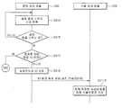
- the driving control unit 230 of each driving control module 200 operates the state notifying unit 240 in step S11 and reads the signal from the angle sensor 211 to read the signal from the driving control module 200, That is, the current rotation angle, that is, the rotation angle of the part related to the drive control module, and stores it in the storage unit 260 (S12).
- the drive control unit 230 of the drive control module 200 compares the determined current angle with the previous angle in the previous step, and determines whether the current angle and the previous angle are equal to each other (S13).
- the first drive control module 200 which is one drive control module, adjusts the angle of the corresponding part for setting the identification number State, that is, the identification number setting operation by the user is being performed, and the remaining second and third drive control modules 200 are in a state in which the angle adjustment of the user is not yet performed for setting the identification number, It is assumed that the operation of setting the identification number by the user is not performed.
- the drive controller 230 controls the state in which the angle adjustment of the corresponding part by the user is not performed, It is judged that the angle adjustment for the relevant part is not yet performed for setting the number.
- the drive control unit 230 of the drive control module 200 proceeds to step S12 while maintaining the driving state of the status notification unit 240 and reads the detection signals output from the angle sensor 211 respectively. Accordingly, the user recognizes that the identification number setting operation of the second and third drive control modules 200 is not yet performed using the operating status notification unit 240.
- the drive control unit 230 of the first drive control module 200 determines that the state of the first drive control module 200 is currently being adjusted for the identification number setting by the user, (S14). ≪ / RTI >
- the drive controller 230 of the drive control module 200 having the current angle different from the previous angle determines the identification number corresponding to the determined current angle, and stores it in the storage unit 260 (S15).
- the determined identification number is transmitted to the central control module 100 using the communication unit 22 (S16).
- the drive control unit 230 of each drive control module 200 sets the operation angle range And the identification number corresponding to the determined operating angle range is determined.
- the central control module 100 stores the current identification number transmitted from the corresponding drive control module, for example, the first drive control module 200, in the storage unit 140 (S17).
- the user sets the setting end switch (" SW1 to inform the operation control unit 120 of the central control module 100 that the identification number setting operation is completed.
- the operation control unit 120 of the central control module 100 reads the signal from the setting end switch SW1 and judges whether the setting end switch SW1 is operated or turned on (S18, S19 ).
- the operation control unit 120 determines whether the setting end switch SW1 operated by the user is on or not by using the identification number stored in the storage unit 140 transmitted from each drive control module 200, It is determined whether there is a duplicate identification number (S110, S111).
- the central control module 100 uses a known method for determining duplication of identification numbers.
- the operation control unit 120 determines that there is a plurality of drive control modules 200 to which the same identification number is assigned due to the mistake of the angle operation by the user .
- the central control module 100 determines whether or not the setting time has elapsed after transmitting the identification number setting command packet, and when the set time has elapsed The comparison operation of the identification number transmitted from the drive control module 200 can be performed.
- the operation control unit 120 proceeds to step S10 to transmit an identification number setting command packet to all the drive control units 120 to start the identification number setting operation for all the drive control modules 200 again.
- the identification number of each drive control module 200 stored in the storage unit 140 may be deleted by the operation control unit 120.
- the operation control part 120 normally performs the identification number assignment operation of all the drive control modules 200 And stores the identification number already stored in the storage unit 140 as the final identification number (S112). At this time, the operation control unit 120 of the central control module 100 may output the final identification number to the information output unit 130 and inform the user of the identification number set in the drive control module 200.
- the operation control unit 120 transmits an identification number setting end command packet (that is, an ID setting end command packet) to each drive control module 200 (S113) (200).
- the drive control unit 230 of the drive control module 200 stores the current identification number stored in the storage unit 260 as its final identification number, and ends the identification number setting operation (S114).
- the drive control unit 230 of each drive control module 200 uses the detection signal of the angle sensor 211, which is the identification number setting operation detection sensor, An identification number corresponding to the size of the angle determined in accordance with the operation state to be performed is stored in the storage unit 260, And sets the identification number of the drive control module 200 as an identification number.
- the drive control module 200 transmits its identification number to the central control module 100 regardless of the request of the central control module 100, Lt; / RTI >
- each drive control module 200 can transmit its own identification number according to a request of the central control module 100.
- each drive control module 200 when an identification number setting command packet is transmitted from the central control module 100 to each drive control module 200 (S10), each drive control module 200 has already received an identification number setting command packet As described above, each corresponding portion is operated in a predetermined operating angle range, and an identification number corresponding to the operated angle is acquired and stored in the storage unit 260 (S11-S15).
- the central control module 100 reads a signal from the setting end switch SW1 and determines whether the setting end switch SW1 is turned on by the user (S21, S22).
- the operation control unit 120 of the central control module 100 transmits an identification number request command to all the drive control modules 200 through the bus when the setting end switch SW1 is determined to be operated by the user at step S22 (S23).
- each drive control module 200 having received the identification number request command reads the identification number of the currently determined own stored in the storage unit 260, and sends the identification number read through the bus to the central control module 100 (S24).
- the identification number transmission timing of each drive control module 200 can be determined according to its own identification number.
- the delay time is determined according to the size of the identification number, And transmits its own identification number at a time when a predetermined delay time has elapsed after the number request command is transmitted.
- the delay time is' 0'
- the delay time is' 1ms' when the identification number is' 2 '
- the delay time is' 2 ms'.
- the delay time corresponding to the size of the identification number is already stored in the storage unit 260.
- the operation control unit 120 of the central control module 100 stores the identification numbers transmitted from all the drive control modules 200, (S25). Then, as already described with reference to FIG. 4B, it is determined whether there is an identification number duplicated in the identification number transmitted from each drive control module 200 (S111), and the duplicated identification number The process goes to step S10 to start the identification number setting operation of all the drive control modules 200 again.
- the operation control unit 120 of the central control module 100 transmits, to each of the transmitted drive control modules 200, (S112), and transmits an identification number setting end command packet to all the drive control modules 200 via the bus (S113).
- each drive control module 200 stores the identification number stored in the current storage unit 260 as its final identification number according to the transmission of the setting end command packet (S114).
- the drive control module 200 controls the angle of the corresponding part and acquires the identification number corresponding to the magnitude of the determined angle as in the operation in steps S11 to S111 in Figs. 4A and 4B,
- the central control module 100 transmits the identification number to the central control module 100.
- the central control module 100 transmits an identification number setting command packet to all the drive control modules 200 connected to the central control module 100 to identify all the drive control modules 200 Perform number setting operation.
- each of the drive control modules 201-203 performs the same operation as described above, determines a corresponding identification number, and then transmits the determined identification number to the central control module 100,
- the identification number of each drive control module 201-203 is stored in the storage unit 140 (S10-S17).
- the identification number setting end command packet is transmitted to the terminal 201-203 to terminate the identification number setting operation.
- the operation of the central control module 100 is performed in the case where the drive control modules (e.g., the second and third drive control modules 202 and 203)
- the control unit 120 re-establishes the identification number of the drive control modules 202 and 203 having duplicate identification numbers.
- the central control module 100 transmits an identification number setting command packet along with the duplicated identification number to the bus (S115).
- the first to third drive control modules 201-203 receiving the identification number setting command packet transmitted from the central control module 100 compare the transmitted identification number with the identification number stored in the storage unit 260 (S116).
- the drive control modules e.g., the second and third drive control modules 202 and 203 having the same identification number as the transmitted identification number proceed to step S11 according to the transmitted identification number setting command packet, So that the operation of setting the identification number is performed again.
- the drive control module e.g., the first drive control module 201 having the identification number different from the transmitted identification number ignores the transmitted identification number setting command packet so that the identification number setting operation is not performed again .
- the corresponding drive control modules 202 and 203 having duplicate identification numbers perform the identification number setting operation again.
- the drive control modules 202 and 203 have an information output unit for outputting information
- the identification numbers transmitted from the central control module 100 can be output, and the corresponding drive control modules 202, 203, and the setting operation to the correct identification number is performed again.
- unnecessary power consumption of the identification number setting device is prevented, and the load applied to each drive control module 200 is reduced to a minimum value because the repetitive identification number setting operation for the drive control module 200, .
- each of the drive control modules 200 may transmit an identification number of a predetermined identification number according to an identification number request command by the central control module 100.
- each drive control module 200 determines a value corresponding to the determined rotation angle according to the angle adjustment of the corresponding part according to the operation of the user as the identification number.
- the drive control module 200 can determine the value of the identification number according to the number of breaks of the corresponding part.
- the identification number setting method shown in FIGS. 7A and 7B is the same as the setting method shown in FIGS. 4 and 4B except for the identification number giving method for each drive control module 200.
- FIG. 7A and 7B is the same as the setting method shown in FIGS. 4 and 4B except for the identification number giving method for each drive control module 200.
- the operation control unit 120 of the central control module 100 firstly sets an identification number for a plurality of drive control modules 200 initially determined with the same identification number
- An identification number setting command packet is transmitted to all the drive control modules 200 connected to the bus via the bus (S30).
- the drive control unit 230 of the drive control module 200 receiving the identification number setting command packet operates the status notification unit 240 to indicate that the current operation status is the operation status for setting the identification number, (S31).
- the user performs an identification number setting operation for all the drive control modules 200 in which the status notification unit 240 is operated.
- the user performs a breaking operation for the portion related to each drive control module 200 by a predetermined number of times.
- the user already knows the identification number to be given to each drive control module 200, and knows the number of times of breaking operation performed according to the identification number assigned thereto.
- the user performs an operation of folding a portion (e.g., a wrist joint portion) related to each drive control module 200 by a predetermined number of times.
- a portion e.g., a wrist joint portion
- the angular velocity of the corresponding portion of the drive control module 200 is changed, and the drive control unit 230 determines whether or not a bending operation by the user has occurred using the change in angular velocity .
- each corresponding drive control unit 230 calculates the angular velocity of the current angle detected by the angle sensor 211, and determines the number of times the corresponding portion is broken.
- each drive control module 200 reads the detection signal output from the angle sensor 211, determines the current angle, stores it in the storage unit 260, The angular velocity is calculated and stored in the storage unit 260 (S32).
- the drive control unit 230 compares the determined current angle with the previous angle, and determines whether they are the same (S33).
- the drive control unit 230 determines that the user's operation for setting the identification number of the drive control module 200 is not yet performed.
- the drive control unit 230 of the drive control module 200 reads the detection signal of the angle sensor 211 while continuing to operate the status notification unit 240 (S32). On the other hand, if it is determined that the current angle is changed (S33), the drive control unit 230 determines that the user's operation for the corresponding part is taken for the identification defense setting. Accordingly, the drive control unit 230 stops driving the status notification unit 240 (S343), and determines the number of times the user breaks the corresponding portion.
- the drive control unit 230 of the drive control module 200 determines whether a bending operation has occurred using the determined angular velocity (S35).
- the change direction of the angle changes from a first direction (e.g., forward direction) to a second direction opposite to the second direction (e.g., reverse direction), or when the angular velocity is zero, .
- the drive control unit 230 increases the number of tiltings by 1 in the current tilting number and stores the increased number in the storage unit 260 as the current tilting number S36).
- the detection signal of the angle sensor 211 is read to determine the angle, and it is determined whether or not the tilting operation of the corresponding portion has been performed using the angular velocity (S37, S35).
- step S35 if it is determined in step S35 that the bending operation does not occur for the corresponding part, the drive control unit 230 of the drive control module 200 determines that the bending operation does not occur, (Step S38).
- the drive control unit 230 determines that the further tilting operation by the user is not performed. Accordingly, the drive control unit 230 determines the current number of breaks stored in the storage unit 260, selects an identification number corresponding to the determined number of times of breakage, and stores the identification number of the corresponding drive control module 200 In the storage unit 260, and sets its own identification number to the current identification number from the initial number (S39).
- an identification number corresponding to the number of breaks is already stored in the storage unit 260 using a look-up table or the like.
- the drive control unit 230 of the drive control module 200 having its own identification number transmits its determined identification number to the central control module 100 and transmits the identified identification number to the storage unit 140 of the central control module 100 (S310, S311).
- the drive control unit 230 reads the detection signal output from the angle sensor 211 again, (S312).
- the operation control unit 120 of the control unit 100 performs the same operations as steps S18 to S114 in Figs. 4A and 4B.
- the operation control unit 120 of the central control module 100 determines the operation state of the setting end switch SW1, and when the operation of the setting end switch SW1 is performed, identification of all the drive control modules 200 transmitted If there is an identical identification number, an identification defense setting command packet is transmitted to all the drive control modules 200 (S10). If all identification numbers of all the drive control modules 200 are set When there is no identical identification number, an identification number setting termination command packet is transmitted to all the drive control modules 200 so that the current identification number is finally stored in the identification number of each drive control module 200 (S314 to S3110).
- an angle sensor 211 is used as a tilt sensor for detecting the breaking state of the user.
- the present invention is not limited to this, and in an alternative example, it is possible to detect other changing factors such as angular velocity, voltage, and current that change according to the breaking action of the corresponding part by the user,
- the sensor may be a voltage sensor 212, a current sensor 213, or other types of sensors such as angular velocity.
- another sensor for detecting the bent state such as the voltage sensor 212 and the current sensor 213 may also function as an identification number setting motion detection sensor for detecting whether or not the user sets the identification number.
- the identification number setting operation of the drive control module 200 of each part is performed by the user's bending operation on the corresponding part, so that the identification number setting operation is performed more easily and conveniently than when the angle adjustment is used.
- the identification number of the drive control module 200 is set according to the angular size of the corresponding part, and in the case of FIGS. 7A and 7B, the identification number of the drive control module 200 is the number of breaks .
- the identification number of the drive control module 200 is automatically assigned to the drive control module 200 according to the sequence in which the identification number setting operation is sequentially performed.
- the identification number given to each drive control module 200 may be a value calculated by adding a predetermined value (e.g., 1) to a previously assigned identification number.
- one central control module 100 has three drive control modules, that is, first to third drive control modules 201-203.
- the operation control unit 120 of the central control module 100 transmits an identification number setting command packet to all the drive control modules 201-203 via the bus (S40), and sends the identification number setting command packet to each drive control module 201-203
- the drive control unit 230 of each drive control module 201-203 informs the external user to perform the identification number setting operation by operating the status notification unit 240 (S41) .
- the user performs an identification number setting operation for the drive control module 201-203 in which the status notification unit 240 is operated.
- FIGS. 8A and 8B show a method using the angle adjustment shown in FIGS. 4A and 4B.
- the portion corresponding to the drive control module 201 is moved by the corresponding angle in the corresponding direction according to the operation of the user.
- the drive control unit 230 stops driving the status notification unit 240 (S42-S44), and uses the data stored in the storage unit 260 to identify a corresponding identification number according to the determined angle to its own identification number And stores it in its own storage unit 2600 (S45), and transmits the set identification number (S46).
- the set identification numbers of the first drive control module 201 are transmitted not only to the central control module 100 but also to the remaining drive control modules 202 and 203 connected to the same bus.
- the operation control unit 120 of the central control module 100 stores the transmitted identification number in the storage unit 140 (S431).
- the other drive control modules 202 and 203 receiving the identification number from the first drive control module 201 store the transmitted identification number in the storage unit 260 (S414 and S424).
- the first identification number setting operation for the drive control module 201 is completed for the first time among the plurality of drive control modules 201-203.
- the user selects one of the remaining drive control modules 202 and 203 (e.g., the second drive control module 202) and performs the identification number setting operation in the same manner as described above.
- one of the remaining drive control modules 202 and 203 e.g., the second drive control module 202
- the second drive control module 202 compares the current angle determined using the sensing signal of the angle sensor 211 with the previous angle, and the operation of setting the identification number of the user to the second drive control module 202 is performed If it is determined that the identification number setting operation is performed, the operation of the status notification unit 240 is stopped (S412, S413, and S415).
- the drive control unit 230 of the second drive control module 202 refers to the identification number stored in the current storage unit 260, that is, the identification number of the most recently stored first drive control module 201 And determines the identification number of the second drive control module 202.
- the drive controller 230 of the second drive control module 202 stores '1' in the identification number of the first drive control module 201 stored in step S414, which is the most recently stored identification number, And sets the calculated value as its own identification number and stores it as its own identification number in the storage unit 260 (S416).
- the determined identification number is transmitted to the central control module 100 and the other drive control modules 201 and 203 through the bus (S417).
- the central control module 100 stores the transmitted identification number in the storage unit 140 (S432).
- the first and third drive control modules 201 and 203 which are other drive control modules, determine whether or not to store the transmitted identification number according to whether the identification number setting operation by the user has been performed.
- the drive control unit 230 determines whether the user's identification number setting operation for the corresponding drive control module 201-203 has been performed using the value of the status flag indicating whether or not the identification number setting operation has been performed by the user can do.
- the drive control module e.g., the first drive control module 201 in which the identification number setting operation by the user is completed through the already described operation does not store the identification number transmitted from the second drive control module 202 Do not.
- the drive control module (for example, the second drive control module 203) in a state in which the identification number setting operation by the user is not yet performed stores the identification number transmitted from the second drive control module 202 S425).
- the identification number of the second drive control module 202 in which the identification number setting operation is performed a second time, is determined through this process.
- the operation of the remaining third drive control module 203 is also performed in the same manner as the operation of the second drive control module 202, and the identification number of the third drive control module 203 is determined and stored.
- the operation of the status notifying unit 240 is stopped, the set value is added to the ID number stored in the current storage unit 260, (S426, S427).
- the determined identification number is transmitted to the central control module 100 and the remaining drive control modules 201 and 202 (S428).
- the central control module 100 stores the transmitted identification number in the storage unit 140 (S433). However, since the remaining drive control modules 201 and 202 have already completed their identification number setting operation, they do not store the identification number of the transmitted third drive control module 203 and ignore it.
- the drive control module 201 in which the identification number is first set, sets the identification number to a value determined by the user by the identification number setting operation (e.g., the first setting operation), and sequentially sets the identification number
- the remaining drive control modules 202 and 203 to be performed are previously received by the bus through the identification number setting operation (for example, the second setting operation) of the user sequentially input to each of the remaining drive control modules 202 and 203 And sets a value that does not overlap with the identification number of the other drive control module 201 as its own identification number.
- the sequentially determined identification number may be a value calculated by adding the set value to the identification number of the other drive control module determined in the immediately preceding step. Therefore, the operation load on each of the drive control modules 201-203 is reduced, and the probability that the same identification number is given to the plurality of drive control modules is greatly reduced, and the accuracy of the identification number setting operation is greatly improved. In addition, the user's convenience is also greatly improved by reducing the user's actions to be performed to set the identification number.
- the central control module 100 uses the operation state of the setting end switch SW1, So that the identification number setting operation of the drive control module 100 can be performed again in which the identification number is duplicated due to the presence of the same identification number, and when the duplicate identification number does not exist, the drive control module 201-203) to store the current identification number as the final identification number (S434-S439, S46, S417, S429).
- the drive control module 200 may further include a random number generator 270 connected to the drive control unit 230 and operated by the drive control unit 230 to generate a random number
- a random number generator 270 connected to the drive control unit 230 and operated by the drive control unit 230 to generate a random number
- the drive control unit 230 of the drive control modules 202 and 203 stops the operation of the status notification unit 240 and outputs the identification number, which is stored in the storage unit 260, (270), generates a random number, reads the generated random number, and determines its own identification number.
- the operation control unit 120 of the central control module 200 may output the identification number transmitted to the information output unit 130 to inform the user of the identification number for the drive control module 200.
- the drive control modules 202 and 203 may use one identification number instead of the immediately-generated identification number, for example, a first drive control module (e.g., a first drive control module 201) is defined as a reference identification number (i.e., a reference value), and a random number generated by using the reference identification number as a seed value of the random number generator 270 is transmitted to the drive control modules 202 and 203 .
- a first drive control module e.g., a first drive control module 201
- a reference identification number i.e., a reference value
- the drive control modules 202 and 203 store the identification number transmitted first after transmitting the identification number setting command packet as the reference identification number, and then determine that the identification number setting operation for the user is performed The driving of the state driver 240 is stopped. Next, the drive control modules 202 and 203 input the reference identification number as a seed value to the random number generator 270, and operate the random number generator 270 to read the generated random number and set the identification number of the drive number. In this case, the drive control modules 202 and 203 do not store the identification numbers transmitted from the other drive control modules 202 and 203 after the reference identification number.
- each drive control module 200 includes the random number generator 270
- the drive control module 200 in the alternative alternative example not only calculates the angles and the number of breaks of the corresponding part, but also the number of random numbers generated by the random number generator 170 The identification number of the corresponding drive control module 200 can be determined.
- the identification number setting command packet is transmitted from the operation control unit 120 of the central control module 100 (S50) as described with reference to FIG. 4A
- the user ID number setting operation is performed for the corresponding drive control module 200 and the identification number according to the user identification number setting operation is determined using the stored value of the storage unit 260
- the drive control unit 230 of the drive control module 200 inputs the random number generator 270 with the determined identification number as a seed value to stop the operation of the random number generator 270, Generates a random number, reads the generated random number, and stores it as its own identification number (S55, S56).
- the drive control unit 230 transmits the determined identification number to the central control module 100 (S57) and stores it as an identification number (S58).
- the operation control unit 120 of the central control module 100 outputs the identification number determined through the information output unit 130 so that the user can know the determined identification number (S59).
- the central control module 100 may control the operation of the central control module 100 according to the request of the central control module 100 according to the method described with reference to FIGS. 5A and 5B and FIGS. 6A and 6B. It is natural that the identification number setting operation can be performed only in the drive control module 200 having the duplicated identification number if the identification number is duplicated.
- the method of setting the identification number of the drive control module 200 may be one of a method of setting the identification number using the angle size, the number of breaks, the initial identification number,
- the identification number for the drive control module 200 can be determined on the basis of the number of touches performed in the corresponding part after the status informing unit 240 is operated using a touch sensor, Therefore, the identification number for the drive control module 200 can be determined.
- the touch sensor or the like is for detecting the user's operation for setting the identification number
- the touch sensor also functions as an identification number setting motion detection sensor like the angle sensor.
- the motor in the drive control module 200 performs the rotational motion
- the motor as the driver in the drive control module 200 is not limited to the motor that performs the rotational motion.
- the present invention can also be applied to a case where the driver in the drive control module is a linear motor, for example, a linear motor.
- the driver in the drive control module is a linear motor, for example, a linear motor.
- angular displacement and “angular velocity” in the embodiments described above should be interpreted as “displacement” and “velocity”, respectively.
- the “ rotational direction " should be interpreted as “ direction of motion ".
- the sensor for detecting the operating state of the linear motion actuator is a position sensor for detecting the position, such as the movement distance sensor, and the position sensor functions as the identification number setting motion detection sensor.
Priority Applications (3)
| Application Number | Priority Date | Filing Date | Title |
|---|---|---|---|
| US15/737,314 US20190163658A1 (en) | 2017-11-24 | 2017-11-24 | Master and slave, and identification number setting apparatus |
| PCT/KR2017/013530 WO2019103202A1 (ko) | 2017-11-24 | 2017-11-24 | 마스터 기기 및 슬레이브 기기, 그리고 이들을 포함하는 식별번호 설정 장치 |
| CN201780037851.5A CN110073637B (zh) | 2017-11-24 | 2017-11-24 | 主机设备及从机设备、以及包括其的识别号设定装置 |
Applications Claiming Priority (1)
| Application Number | Priority Date | Filing Date | Title |
|---|---|---|---|
| PCT/KR2017/013530 WO2019103202A1 (ko) | 2017-11-24 | 2017-11-24 | 마스터 기기 및 슬레이브 기기, 그리고 이들을 포함하는 식별번호 설정 장치 |
Publications (1)
| Publication Number | Publication Date |
|---|---|
| WO2019103202A1 true WO2019103202A1 (ko) | 2019-05-31 |
Family
ID=66631580
Family Applications (1)
| Application Number | Title | Priority Date | Filing Date |
|---|---|---|---|
| PCT/KR2017/013530 WO2019103202A1 (ko) | 2017-11-24 | 2017-11-24 | 마스터 기기 및 슬레이브 기기, 그리고 이들을 포함하는 식별번호 설정 장치 |
Country Status (3)
| Country | Link |
|---|---|
| US (1) | US20190163658A1 (zh) |
| CN (1) | CN110073637B (zh) |
| WO (1) | WO2019103202A1 (zh) |
Citations (5)
| Publication number | Priority date | Publication date | Assignee | Title |
|---|---|---|---|---|
| US20080040515A1 (en) * | 2003-12-22 | 2008-02-14 | Ralf Schaetzle | Method and System for Automated Configuring of a Hart Multi-Drop System |
| US20100332903A1 (en) * | 2004-12-02 | 2010-12-30 | Texas Instruments Incorporated | Locating and labeling device in a multi drop configuration |
| US20120271924A1 (en) * | 2011-04-19 | 2012-10-25 | Spitaels James S | System and method for automatically addressing devices in a multi-drop network |
| US20130268231A1 (en) * | 2012-04-06 | 2013-10-10 | Seiko Epson Corporation | Sensor system and sensor module identification method |
| US20160109270A1 (en) * | 2014-03-31 | 2016-04-21 | Llc "Topcon Positioning Systems" | Automatic identification of sensors |
Family Cites Families (13)
| Publication number | Priority date | Publication date | Assignee | Title |
|---|---|---|---|---|
| ATE283505T1 (de) * | 2000-04-18 | 2004-12-15 | Elmos Semiconductor Ag | Verfahren zur automatischen vergabe von adressen an die teilnehmer eines bussystems |
| US6915171B2 (en) * | 2001-04-26 | 2005-07-05 | Visteon Global Technologies, Inc. | Automatic procedure for locating actuator addresses on a bus system |
| US20030052180A1 (en) * | 2001-09-19 | 2003-03-20 | Trw Inc. | Method and apparatus for establishing addresses for plural actuators connected to a bus |
| WO2004085121A1 (ja) * | 2003-03-27 | 2004-10-07 | Sony Corporation | ロボット装置及びロボット装置の制御方法 |
| US7676342B2 (en) * | 2004-12-23 | 2010-03-09 | Asml Netherlands B.V. | Sensor assembly, digital serial bus and protocol, sensor network, and lithographic apparatus and system |
| DE102005056294B4 (de) * | 2005-11-24 | 2016-04-28 | Sew-Eurodrive Gmbh & Co Kg | Verfahren zum Zuordnen von Adressen an Busteilnehmer eines Bussystems und Anlage |
| JP2008062802A (ja) * | 2006-09-07 | 2008-03-21 | Denso Corp | 通信システム及びアドレス割り当て方法 |
| CN101355482B (zh) * | 2008-09-04 | 2011-09-21 | 中兴通讯股份有限公司 | 实现嵌入式设备地址顺序识别的设备、方法和系统 |
| US8494370B2 (en) * | 2010-08-16 | 2013-07-23 | International Business Machines Corporation | Locating components in data center |
| WO2013191494A1 (ko) * | 2012-06-20 | 2013-12-27 | (주)휴즈플로우 | 정보 처리 방법 및 장치, 그리고 데이터 처리 방법 및 이를 이용하는 장치 |
| US9660968B2 (en) * | 2015-09-25 | 2017-05-23 | Intel Corporation | Methods and apparatus for conveying a nonce via a human body communication conduit |
| US9852094B2 (en) * | 2015-12-07 | 2017-12-26 | Allegro Microsystems, Llc | Device configuration using a magnetic field |
| KR102381371B1 (ko) * | 2015-12-10 | 2022-03-31 | 삼성전자주식회사 | 근거리 통신을 이용한 정보 제공 시스템 및 방법 |
-
2017
- 2017-11-24 CN CN201780037851.5A patent/CN110073637B/zh active Active
- 2017-11-24 US US15/737,314 patent/US20190163658A1/en not_active Abandoned
- 2017-11-24 WO PCT/KR2017/013530 patent/WO2019103202A1/ko active Application Filing
Patent Citations (5)
| Publication number | Priority date | Publication date | Assignee | Title |
|---|---|---|---|---|
| US20080040515A1 (en) * | 2003-12-22 | 2008-02-14 | Ralf Schaetzle | Method and System for Automated Configuring of a Hart Multi-Drop System |
| US20100332903A1 (en) * | 2004-12-02 | 2010-12-30 | Texas Instruments Incorporated | Locating and labeling device in a multi drop configuration |
| US20120271924A1 (en) * | 2011-04-19 | 2012-10-25 | Spitaels James S | System and method for automatically addressing devices in a multi-drop network |
| US20130268231A1 (en) * | 2012-04-06 | 2013-10-10 | Seiko Epson Corporation | Sensor system and sensor module identification method |
| US20160109270A1 (en) * | 2014-03-31 | 2016-04-21 | Llc "Topcon Positioning Systems" | Automatic identification of sensors |
Also Published As
| Publication number | Publication date |
|---|---|
| CN110073637A (zh) | 2019-07-30 |
| CN110073637B (zh) | 2022-05-13 |
| US20190163658A1 (en) | 2019-05-30 |
Similar Documents
| Publication | Publication Date | Title |
|---|---|---|
| WO2022035136A1 (ko) | 무인 카페 운영 시스템 및 방법 | |
| WO2019017696A1 (ko) | 신발 끈 조절장치 및 이를 구비하는 신발 | |
| WO2017034289A1 (ko) | 패널구동장치 및 패널구동방법 | |
| WO2019078475A1 (ko) | 병렬연결 구조의 배터리 팩의 히터 제어 시스템 및 그 방법 | |
| WO2014104843A1 (ko) | 발광 다이오드 조명 장치의 제어 회로 | |
| WO2018155975A1 (ko) | 입력장치 | |
| WO2015037853A1 (ko) | 터치패널 | |
| WO2019103202A1 (ko) | 마스터 기기 및 슬레이브 기기, 그리고 이들을 포함하는 식별번호 설정 장치 | |
| WO2017195986A1 (ko) | 가로등의 제어방법 및 이를 이용한 제어장치 | |
| WO2018034550A1 (ko) | Dc-dc 전압 컨버터의 동작 모드를 제어하기 위한 제어 시스템 | |
| EP3240983A1 (en) | Refrigerator | |
| WO2013062379A2 (ko) | 네트워크형 엑츄에이터 모듈 제어방법 | |
| WO2021029608A1 (ko) | 블렌더 | |
| WO2019177433A1 (ko) | 디지털 온도 센서의 통신 주소 설정 장치 | |
| WO2015147527A1 (ko) | 배터리팩, 셀 모듈 및 셀 모듈 조립체 | |
| WO2019088423A1 (ko) | 차량 제어 장치 | |
| WO2018080279A1 (ko) | 액체렌즈 및 이를 포함하는 카메라 모듈 및 광학기기 | |
| WO2018182347A1 (ko) | 커뮤니케이션 로봇 | |
| WO2024039117A1 (ko) | 크랙 검출 장치, 크랙 검출 방법 및 데이터 구동 장치 | |
| WO2023210920A1 (ko) | 멀티 디스플레이 컨트롤을 위한 전자 장치 | |
| WO2012008633A1 (ko) | 정전용량 터치센서 | |
| WO2020101315A1 (ko) | 조리 장치 및 그 제어 방법 | |
| WO2018026113A1 (ko) | 센싱장치, 패널구동장치 및 표시장치 | |
| WO2022114446A1 (ko) | 멀티 웨이브 생성시스템 | |
| WO2023136382A1 (ko) | 회전형 디스플레이 장치 |
Legal Events
| Date | Code | Title | Description |
|---|---|---|---|
| 121 | Ep: the epo has been informed by wipo that ep was designated in this application |
Ref document number: 17932963 Country of ref document: EP Kind code of ref document: A1 |
|
| NENP | Non-entry into the national phase |
Ref country code: DE |
|
| 122 | Ep: pct application non-entry in european phase |
Ref document number: 17932963 Country of ref document: EP Kind code of ref document: A1 |