WO2019103154A1 - Dispositif de relevé, système de relevé, procédé de relevé et programme de relevé - Google Patents
Dispositif de relevé, système de relevé, procédé de relevé et programme de relevé Download PDFInfo
- Publication number
- WO2019103154A1 WO2019103154A1 PCT/JP2018/043566 JP2018043566W WO2019103154A1 WO 2019103154 A1 WO2019103154 A1 WO 2019103154A1 JP 2018043566 W JP2018043566 W JP 2018043566W WO 2019103154 A1 WO2019103154 A1 WO 2019103154A1
- Authority
- WO
- WIPO (PCT)
- Prior art keywords
- laser scanner
- positioning data
- reflecting prism
- total station
- positioning
- Prior art date
Links
Images


Classifications
-
- G—PHYSICS
- G01—MEASURING; TESTING
- G01C—MEASURING DISTANCES, LEVELS OR BEARINGS; SURVEYING; NAVIGATION; GYROSCOPIC INSTRUMENTS; PHOTOGRAMMETRY OR VIDEOGRAMMETRY
- G01C15/00—Surveying instruments or accessories not provided for in groups G01C1/00 - G01C13/00
-
- G—PHYSICS
- G01—MEASURING; TESTING
- G01C—MEASURING DISTANCES, LEVELS OR BEARINGS; SURVEYING; NAVIGATION; GYROSCOPIC INSTRUMENTS; PHOTOGRAMMETRY OR VIDEOGRAMMETRY
- G01C15/00—Surveying instruments or accessories not provided for in groups G01C1/00 - G01C13/00
- G01C15/02—Means for marking measuring points
- G01C15/06—Surveyors' staffs; Movable markers
Definitions
- the present invention relates to surveying using a laser scanner.
- Patent Documents 1 to 3 There is known a technology for carrying out surveying while moving a surveying instrument such as a laser scanner mounted on a carriage or the like (see, for example, Patent Documents 1 to 3).
- Patent No. 5748566 gazette JP, 2014-173990, A JP, 2017-20972, A
- the present invention aims to provide a technique that can achieve high working efficiency in a technique of mounting a laser scanner on a moving body, alternately performing movement and stopping, and performing laser scanning at the time of stopping.
- the invention according to claim 1 is based on positioning data by a laser scanner equipped with a first reflecting prism, and positioning data by a total station fixed to the ground and comprising a second reflecting prism.
- a guidance process for guiding the moving body to a predetermined stop position based on an external determination element calculation unit that calculates an external determination element of the laser scanner and positioning data of the first reflecting prism by the total station A survey processing device including a guidance processing unit for performing the calculation, in the calculation of the external orientation element of the laser scanner, the positioning data by the laser scanner is positioning data of the second reflecting prism, and the total station Said positioning data according to is the positioning data of said first reflecting prism It is the amount apparatus.
- the invention according to claim 2 is a surveying system comprising the surveying instrument according to claim 1 and a leveling device for leveling the laser scanner.
- the invention according to claim 3 is characterized in that, in the invention according to claim 2, the positioning of the first reflecting prism by the total station is performed after the leveling operation of the laser scanner by the leveling device. I assume.
- the invention according to claim 4 is based on positioning data by a laser scanner equipped with a first reflecting prism, and positioning data by a total station fixed to the ground and comprising a second reflecting prism.
- the invention according to claim 5 is a program that causes a computer to read and execute the program, wherein the computer is mounted on a moving body and fixed on the ground with positioning data by a laser scanner provided with a first reflecting prism, The movement to a predetermined stop position based on the calculation of the external positioning element of the laser scanner based on the positioning data by the total station provided with the second reflecting prism and the positioning data of the first reflecting prism by the total station. The guidance processing for guiding the body is performed, and the calculation of the external orientation element of the laser scanner is performed by using the positioning data of the first reflecting prism by the total station and the positioning data of the second reflecting prism by the laser scanner. Program for surveying based on
- high work efficiency can be obtained in the technology of mounting a laser scanner on a moving body, alternately performing movement and stopping, and performing laser scanning at the time of stopping.
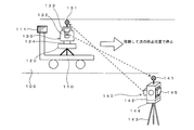
- FIG. 1 shows an outline of an embodiment using the invention.
- FIG. 1 shows a road surface 100, a carriage 110 movable on the road surface 100, an automatic leveling table 120 installed on the carriage 110, and a laser scanner 130 installed on the automatic leveling table 120.
- the target of the laser scan is not particularly limited.
- the ground or slope in a civil engineering work site the wall of a tunnel, the outer surface or the inner surface of a building ( It is also possible to perform laser scanning for indoor wall surfaces and the like.
- the dolly 110 is movable on the road surface 100. Movement is performed manually by manual power. It is also possible to move the carriage 110 by the power of a motor or the like.
- the carriage 110 is stopped at a predetermined position, and in that state, laser scanning is performed on the road surface 100 or the wall surface or the ceiling in the case of a tunnel by the laser scanner 130. With this laser scan, it is confirmed that the road surface is flat or sloped, and if the tunnel is tunneled, the inside displacement or the like. In the case of indoors, confirmation of the present frame and interior is performed.
- the accuracy of the external positioning elements (position and orientation) of the laser scanner at the time of the laser scan is important.
- the effective range is about 30 m at maximum, and it is necessary to stop a trolley
- the above description of the effective range of the laser scanning light is an example, and in fact depends on the specifications of the laser scanner, the incident angle of the laser light to the object, the condition of the object, etc. Yes.
- the TS (total station) 140 is used to guide the laser scanner 130 to the stop position and to accurately specify the position. Further, by measuring the position of the TS 140 by the laser scanner 130, the external orientation element of the laser scanner 130 is specified with high accuracy.
- the all-round reflection prism 131 is fixed to the laser scanner 130, and the all-round reflection prism 141 is fixed to the TS 140.
- the all-round reflecting prisms 131 and 141 have optical characteristics that reflect incident light by changing its direction by 180 degrees in the direction of the entire circumference. If the stop position of the laser scanner 130 is predetermined, the information is stored in the terminal 111. In addition, it is also possible to use a spherical target, a reflecting prism which is not total reflection, and various kinds of targets used for surveying instead of the total reflection prism.
- the TS 140 installed at a known position tracks the all-round reflecting prism 131.
- the movement path of the laser scanner 130 (all-round reflection prism 131) is accurately measured by the positioning function provided in the TS 140, and the data is sent to the terminal 111.
- Data of a predetermined stop position is input to the terminal 111, and guidance information to the stop position of the carriage 110 is displayed on the terminal 111.
- the terminal 111 outputs a notification signal (guide information, notification display, notification sound, etc.). As a result, the carriage 110 can be stopped at a predetermined stop position.
- the laser scanner 130 is leveled by the automatic leveling table 120, and then the precise measurement of the total circumferential reflection prism 141 by the TS 140 is performed.
- the positioning of the all-round reflecting prism 141 is performed by the target (reflection prism) positioning function of the laser scanner 130.
- the position of the all-round reflection prism 141 in the absolute coordinate system is known, and by performing positioning of the all-round reflection prism 141 viewed from the laser scanner 130, the direction and distance of the all-round reflection prism 141 viewed from the laser scanner 130 are I understand. Thereby, the external orientation element (posture) in the absolute coordinate system of the laser scanner 130 is specified. Further, the position of the laser scanner 130 is accurately measured by the TS 140 after the leveling process as described above.
- laser scanning of the road surface 100 by the laser scanner 130 is performed to obtain laser scan data.
- the carriage 110 is moved to the next stop position. The above processing is repeated from the first stop position ⁇ the second stop position ⁇ ... The nth stop position, and the laser scan on the road surface 100 is performed.
- the stop position of the laser scanner 130 is accurately identified by the TS 140. This process is performed after the laser scanner 130 is leveled, and since the positioning accuracy of the TS 140 is high, the stop position of the laser scanner 130 can be accurately determined.
- a precise external orientation element of the laser scanner 130 at the stop position is determined. be able to. Therefore, accurate laser scan data can be obtained.
- processing guidance processing
- processing related to notification of the stop position by the TS 140 is automatically performed, high work efficiency can be obtained.
- the all-round prism 141 from the laser scanner 130, it is possible to obtain an external positioning element of the laser scanner 130 at the stop position.
- Capture, tracking, and positioning of the omnidirectional reflection prism by the TS 140 and the laser scanner 130 can be performed automatically. Thus, the entire work can be performed with high efficiency.
- the TS 140 uses a model available on the market.
- the TS is described in JP-A-2009-229192 and JP-A-2012-20282.
- the base portion 144 fixed on the tripod 143, the horizontal rotation portion 142 capable of horizontal rotation on the base portion 144, and the vertical rotation portion 142 are capable of vertical rotation (elevation angle change and depression angle change).
- a vertically rotating portion 145 and a full circumference reflecting prism 141 fixed to the upper portion of the horizontal rotating portion 142 are provided.
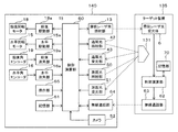
- FIG. 2 shows a TS140 block diagram (configuration diagram).
- Horizontal rotation of the horizontal rotation part 142 of FIG. 1 is performed by the horizontal rotation motor 15 driven by the horizontal drive part 15a of FIG.
- the horizontal rotation angle of the horizontal rotation unit 142 is detected by the horizontal angle encoder 16, and the angle data is output from the horizontal angle measurement unit 16a.
- the rotation of the vertical rotation unit 145 is performed by the vertical rotation motor 18 driven by the vertical drive unit 18 a.
- the rotation angle of the vertical rotation unit 145 is detected by the vertical angle encoder 19, and the angle measurement unit 19 outputs the angle data.
- the all-round reflection prism 131 disposed on the laser scanner 130 is used as a target to be measured by the TS 140.
- tracking light is emitted from the tracking light irradiator 42 to the all-round reflecting prism 131, and the reflected light is received by the tracking light receiver 43.
- the tracking light is irradiated within a certain range, and the horizontal rotation angle of the horizontal rotation portion 142 and the vertical angle of the vertical rotation portion 145 are adjusted so that the all-round reflection prism 131 is positioned at the center of the irradiation range.
- Measurement of the distance from the TS 140 to the all-round reflection prism 131 is performed by the distance measurement light emitted from the distance measurement light irradiator 50.
- the distance measuring light is pulse laser light, and is divided into two by an optical system (not shown), one of which is guided to a reference light path of a known distance provided in the TS 140 as a reference light and the other is It is irradiated.
- the distance measuring light reflected from the all-round reflecting prism 131 is received by the distance measuring light receiving unit 51.
- the reference light is also received by the distance measurement light receiving unit 51.
- the direction of the optical axis of the distance measurement light at the time of the above distance measurement is measured by the horizontal angle encoder 16 and the vertical angle encoder 19. From the distance and direction to the all-round reflection prism 131, positioning of the all-round reflection prism 131 is performed with reference to the TS 140. The calculation concerning this positioning is performed by the control calculation unit 60.
- the control calculation unit 60 is hardware that functions as a computer, and performs calculation related to the operation control and operation of the TS 140 in addition to the calculation related to the positioning of the above-mentioned all-round reflection prism.
- a target device 135 provided with an all-round reflection prism 131.
- the control in this case is described in Japanese Patent Laid-Open No. 2009-229192.
- a fan-shaped laser beam shaped into a fan-shaped beam is emitted from the fan-shaped laser beam irradiation unit 13.
- the irradiation light is irradiated while being scanned in the horizontal direction, and is received by the fan-shaped laser light receiver 6 of the target device 135.
- the fan-shaped laser beam has an N-shape or a W-shape as viewed from the optical axis direction, and the elevation angle from the TS 140 can be calculated from the light reception timing. This calculation is performed by the control calculation unit 62, and the result and the previous light reception time are stored in the storage unit 70.
- the previous elevation angle and the light reception time are transmitted from the wireless communication unit 63 to the wireless communication unit 64 of the TS 140, and based on the contents, the TS 140 calculates the direction of the target device 142 and directs the optical axis to the direction of the target device 135. Turn. As a result, general collimation of the all-round reflection prism 131 of the target device 135 is performed, and thereafter, collimation of the all-round reflection prism 131 by tracking light is performed, and positioning of the all-round reflection prism 131 by distance measurement light is further performed. Is done.
- the TS 140 includes an operation unit 65, a storage unit 61, a wireless communication unit 64, and a camera 52.
- the operation unit 65 includes a display that displays various buttons, switches, and various information for operating the TS 140.
- the storage unit 61 stores various data and an operation program related to the operation of the TS 140.
- the wireless communication unit 64 performs communication with the terminal 111 and the laser scanner 130 and communication with other external devices.
- the camera 52 has the same optical axis as the distance measurement light, and performs moving image shooting of the distance measurement target.
- the laser scanner 130 includes a main unit 132 and an optical unit 133 which are horizontally rotatable with respect to the base unit 134.
- a rotating mirror capable of vertical rotation is disposed in the optical unit 133.
- the distance measuring light from the distance measuring light irradiator 50 (see FIG. 3) disposed in the main body 132 is irradiated on the above-mentioned rotating mirror which vertically rotates. Also, the distance measuring light reflected from the object is reflected by the rotating mirror, and is received by the distance measuring light receiving unit 51 disposed in the main body 132.
- the distance measuring light is continuously pulse irradiated to the rotating mirror, and the laser with respect to the surroundings (or to a specific range) by the laser scanner 130 A scan is performed.
- the laser scanning in the laser scanner 130 is also laser positioning based on the same principle as that of the TS 140 when viewed with one pulse, but the TS 140 performs positioning by aiming at each point, whereas the laser scanner 130 While scanning at a speed of 10 points or more, positioning of the scan point is performed.
- laser scanning a plurality of distance measurement lights are simultaneously irradiated, and positioning of a plurality of points is performed simultaneously.
- the laser scanner is described in, for example, JP-A-2010-151682, JP-A-2008-268004, and US Pat. No. 8,767,190.
- US 2015-0293224 describes a laser scanner which switches scanning directions electronically.
- the laser scanner 130 has a positioning function targeting a reflecting prism.
- the reflection prism in this example, the full circumference reflection prism 141 of the TS 140
- This function is performed using the target (reflecting prism) capturing function similar to that of TS130.
- a laser scan with an increased scan density in the vicinity of the reflecting prism is performed.
- positioning data of the reflecting prism is extracted from the scan data.
- the terminal 111 is fixed to the carriage 110.
- the terminal 111 is fixed at a position where an operator pushing the carriage 111 can easily view and operate.
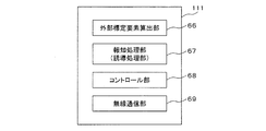
- the block diagram of the terminal 111 is shown in FIG.
- the terminal 111 functions as a controller of the TS 140, a notification device of the stop position of the carriage 110 (laser scanner 130), and a device for calculating the external positioning element (posture) of the laser scanner 130 at the stop position.
- the terminal 111 is hardware that functions as a computer, and is configured of a PC (personal computer), a tablet, a smartphone, or dedicated hardware that can perform the processing described below.
- the terminal 111 includes hardware and functions provided in a display device such as a liquid crystal display, an operation interface such as a numeric keypad and a touch panel display, a communication device, and the like such as a normal PC or tablet.
- the terminal 111 includes an external determination element calculator 66, a notification processor (guide processor) 67, and a controller 68 as functional units. These functional units are realized by installing dedicated application software in the terminal 111 and executing the software by the CPU of the terminal 111. In addition, the form which comprises an arithmetic circuit for exclusive use which performs the function mentioned above by FPGA etc. is also possible.
- the external positioning element calculation unit 66 calculates the external positioning element (in particular, the data of the attitude) of the laser scanner 130 based on the positioning data of the all-round reflection prism 141 performed by the laser scanner 130.
- the position of the laser scanner 130 at the stop position is specified by positioning using the TS 140, and the position data is received by the wireless communication unit 69.
- the attitude of the laser scanner 130 can be obtained as follows.
- the laser scanner 130 measures the position of the all-round reflection prism 141. At this time, the direction of the all-round reflection prism 141 viewed from the laser scanner 130 is obtained. Thereby, a directional line from the position of the laser scanner 130 to the position of the TS 140 (the position of the reflecting prism 141) is obtained.
- the horizontal angle shall be measured clockwise with respect to north.
- the direction of the above-mentioned direction line is 45 ° (the direction of the northeast).
- the relationship between the reference direction of the horizontal angle in the laser scanner 130 and the direction of the direction line is obtained.
- the value in the absolute coordinate system of the reference direction of the horizontal angle of the laser scanner 130 at the position is known.
- the laser scanner 130 secures the level by the function of the automatic leveling table 120, if the reference of the horizontal angle can be determined, the attitude is determined.
- the attitude of the laser scanner 130 at the specific stop position is calculated.
- the above processing is performed by the external orientation element calculator 66.
- the external orientation factor calculator 66 may be disposed on the laser scanner 130 side or the TS 140 side. It is also possible to calculate the external orientation factor of the laser scanner 130 with a device such as a server that is located at a remote location.
- the notification processing unit 67 is processing related to guiding the carriage 110 to a predetermined stop position, and when the carriage 110 (laser scanner 130) approaches or reaches the stop position, the display unit of the terminal 111 And a process of generating an alarm sound.
- the notification processing unit 67 is an example of a guiding device that guides the carriage 110 to the stop position.
- the notification processing unit 67 performs processing of displaying on the display unit of the terminal 111 (for example, a liquid crystal display device of a tablet) an arrow indicating the direction from the current location to the planned stop position and the distance to that. This process can be considered as a process of notifying information on the stop position as image information.
- These notification processes are performed based on the difference between the position data of the predetermined stop position and the position data of the laser scanner 130 determined by the TS 140. For example, the direction and distance to the next stop position are calculated in the terminal 111, and the content is displayed on the display unit of the terminal 111.
- the control unit 68 performs operation control (remote control) of the laser scanner 130 and the TS 140.
- the terminal 111 further includes a wireless communication unit 69.
- the wireless communication unit 69 communicates with the laser scanner 130 and the TS 140 and with other devices.
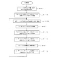
- FIG. 5 is a flow chart showing an example of the procedure of processing executed by the system of FIG.
- a program for executing the process of FIG. 5 is installed in the terminal 111 and executed by the CPU of the terminal 111. It is also possible to store the program in the storage unit 61 of the TS 140 or the laser scanner 130 or an external suitable storage medium.
- the operation of the laser scanner 130 and the TS 140 is remotely controlled by the terminal 111.
- the control in FIG. 5 may be performed by the laser scanner 130 or the TS 140, or may be performed by a server installed at a remote place.
- a laser scan using the laser scanner 130 is performed to check whether the surface condition (flatness or inclination) of the surface of the road surface 100 after the paving work satisfies the specified specifications.
- a laser scanner 130 provided with the all-round reflection prism 131 and a TS 140 provided with the all-round reflection prism 141 are prepared. Relationship between the optical origin (reflection point) of the all-round reflection prism 131 and the optical origin (position of the origin of the position calculation of the scanning point) of the laser scanner 130, the optical origin of the all-round reflection prism 141 and the optical origin of the TS 140 (for positioning The relationship with the origin is previously acquired as known data.
- the position (optical origin) of the laser scanner 130 is specified by performing positioning with the all-round reflecting prism 131 as a target, and the position of the TS 140 is measured by performing positioning with the all-round reflecting prism 141 as a target. (Optical origin) is identified.
- data of the stop position on the road surface 100 is input in advance to the TS 140.
- the effective range of the laser scan on the road surface is estimated to be 30 m, and the stop position of the carriage 110 is set every 20 m in consideration of the overlapping portion.
- the stop position is at the center in the width direction of the road.
- the stop interval is set on a case-by-case basis in relation to the effective range of scan laser light and the scan density, and is set according to the scan target.
- bogie 110 preset on the road surface 100 is marked.
- the TS 140 is installed at a position whose position on the absolute coordinate system is known (step S101). Further, the attitude (azimuth angle) of the TS 140 at this installation position is specified. This is the same as the operation of specifying an external orientation element at the time of installation of a TS (total station) which is usually performed.
- the absolute coordinate system is, for example, a world coordinate system used in GNSS, and is a coordinate system whose position is specified by latitude, longitude, and altitude from the average sea level. The specification of the position is performed, for example, by relative positioning using GNSS. Further, the TS 140 may be installed at a point whose position is specified in advance. As a coordinate system, it is also possible to use a local coordinate system set in the field.
- step S102 the full circumference reflecting prism 131 of the laser scanner 130 on the carriage 110 is captured by the TS 140 (step S102). This is performed by manual collimation, automatic collimation by the target search function of the TS 140, or a combination of approximate collimation and automatic collimation by manual operation.
- the dolly is manually pushed and moved toward the first stop position.
- capturing and positioning of the all-round reflecting prism 131 by the TS 140 are continuously performed.
- a terminal 111 serving as a controller of the TS 140 is fixed to the carriage 110 (a person pushing the carriage 110 may be in hand).
- the direction and distance of the target stop position are displayed on this terminal 111, and guidance of the carriage 110 is performed (step S103). This display is created based on the positioning data of the whole circumference prism 131 by the TS 140 and the position data of the stop position set in advance.
- the operator pushing the carriage 110 pushes the carriage 110 to the stop position while watching the display displayed on the terminal 111.
- the distance to the stop position in the display of the terminal 111 becomes 0, and a notification display notifying that effect is displayed, and a notification sound is emitted from the terminal 111.
- the inclination of the laser scanner 130 is corrected so that the vertical axis of the laser scanner 130 coincides with the vertical direction using the automatic standardizing function of the automatic leveling table 120 (step S104).
- the automatic leveling table 120 a type in which the inclination is detected by various inclination sensors (for example, a method of optically detecting a bubble or the like) and the inclination is adjusted by an actuator or the like based thereon is used.
- the technology related to the leveling table is described, for example, in Japanese Patent Laid-Open No. 2009-14368. A mode is also possible in which leveling is performed not manually but manually or semi-automatically.
- step S105 positioning of the all-round reflection prism 131 fixed to the laser scanner 130 by the TS 140 is performed.
- the positioning data of the all-round reflection prism 131 is sent to the terminal 111.
- the positioning of the laser scanner 130 is performed by measuring the all-round reflection prism 131. The same applies to the all-round reflection prism 141 and the TS 140.
- step S106 positioning of the all-round reflection prism 141 (TS 140) is performed using the laser scanner 130 whose position is accurately specified.
- the positioning data of the all-round reflection prism 141 is sent to the terminal 111.
- an external orientation element of the laser scanner 130 is calculated based on the position of the laser scanner 130 specified on the absolute coordinate system and the position of the TS 140 (step S107).
- the position in the external orientation element of the laser scanner 130 is positioned by the TS 140, and the positioning data is received by the terminal 111. Therefore, the attitude of the laser scanner 130 is calculated here. This process is performed by the external orientation element calculator 66 of the terminal 111.
- step S108 laser scanning of the road surface 100 using the laser scanner 130 is performed.
- the laser scan data of the road surface 100 can be obtained on an absolute coordinate system.
- step S103 When the laser scanning of the road surface 100 at the stop position guided in step S103 is completed, the process returns to the previous step of step S103, movement by guidance by the TS 140 to the next stop position is performed, and the processing from step 104 onward is repeated. . In this way, the movement to a plurality of preset stop positions and the cycle of the laser scanning after stopping there are repeated to acquire the laser scanning data of the road surface.
- the TS 140 guides the carriage 110 to a predetermined stop position and positions the laser scanner 130 at the stop position. Further, the external positioning element of the laser scanner 130 at the stop position is calculated by the positioning of the all-round reflection prism 141 by the laser scanner 130. At this time, there is no need for a person other than pushing and moving the carriage 110, and high work efficiency can be obtained.
- a TS it is also possible to use a TS to specify the position of a part of a plurality of predetermined planned stop positions.
- specification of the stop position without using TS is performed by shape matching.
- Shape matching is a technology for tracking changes in the movement path and external orientation factor of a laser scanner by laser scanning on overlapping regions performed from two different points.
- the TS 140 may be used to specify the first and last planned stop positions, and the other planned stop positions may be specified using shape matching described above.
- the stop position of the carriage 110 is specified using the principle of FIG. 1 and the laser scanner using the above shape matching is used otherwise.
- the planned stop position is specified by the position specifying process 130.
- the laser is based on the positioning data by the laser scanner 130 mounted on the carriage 110 and provided with the all-round reflection prism 131 and the positioning data by the total station 140 fixed on the ground and provided with the all-round reflection prism 141
- the guidance processing for guiding the carriage 110 to a predetermined stop position is performed.
- the positioning data by the laser scanner 130 is the positioning data of the all-round reflecting prism 141, and the total station
- the positioning data by 140 is Content is a positioning data peripheral reflecting prism 131 is disclosed.
- FIG. 2 An example of laser scanning of the inner wall (side wall and ceiling) of a tunnel is shown in FIG.
- the TS 140 is installed in the tunnel, and laser scanning of the inner wall of the tunnel is performed by the laser scanner 130 mounted on the carriage 110.
- the process of FIG. 5 is performed inside the tunnel.
- laser scanning of the road surface is also possible.
- the present invention can be used as a technique for alternately moving and stopping and performing laser scanning at the time of stopping.
Abstract
La présente invention vise à atteindre une efficacité de travail élevée dans une technologie dans laquelle un dispositif de balayage laser est monté sur un corps mobile, un déplacement et un arrêt sont effectués en alternance, et un balayage laser est effectué pendant l'arrêt. À cet effet, l'invention concerne un terminal 111 qui comprend : une unité de calcul d'élément d'orientation externe qui calcule, sur la base de données de positionnement provenant d'un dispositif de balayage laser 130 qui est monté sur un camion 110 et comprenant un prisme à réflexion totale 131, et de données de positionnement provenant d'une station totale 140 qui est fixée au sol et comprenant un prisme à réflexion totale 141, des éléments d'orientation externes du dispositif de balayage laser 130 ; et une unité de traitement de guidage qui effectue un traitement de guidage pour guider le camion 110 vers des positions d'arrêt prédéterminées, sur la base des données de positionnement de prisme à réflexion totale 131 provenant de la station totale 140. Dans le calcul des éléments d'orientation externes du dispositif de balayage laser 130, les données de positionnement provenant du dispositif de balayage laser 130 sont les données de positionnement du prisme à réflexion totale 141, et les données de positionnement provenant de la station totale 140 sont les données de positionnement du prisme à réflexion totale 131.
Priority Applications (1)
| Application Number | Priority Date | Filing Date | Title |
|---|---|---|---|
| JP2019555405A JP7257326B2 (ja) | 2017-11-27 | 2018-11-27 | 測量装置、測量システム、測量方法および測量用プログラム |
Applications Claiming Priority (2)
| Application Number | Priority Date | Filing Date | Title |
|---|---|---|---|
| JP2017226628 | 2017-11-27 | ||
| JP2017-226628 | 2017-11-27 |
Publications (1)
| Publication Number | Publication Date |
|---|---|
| WO2019103154A1 true WO2019103154A1 (fr) | 2019-05-31 |
Family
ID=66631571
Family Applications (1)
| Application Number | Title | Priority Date | Filing Date |
|---|---|---|---|
| PCT/JP2018/043566 WO2019103154A1 (fr) | 2017-11-27 | 2018-11-27 | Dispositif de relevé, système de relevé, procédé de relevé et programme de relevé |
Country Status (2)
| Country | Link |
|---|---|
| JP (1) | JP7257326B2 (fr) |
| WO (1) | WO2019103154A1 (fr) |
Cited By (7)
| Publication number | Priority date | Publication date | Assignee | Title |
|---|---|---|---|---|
| CN110318340A (zh) * | 2019-06-21 | 2019-10-11 | 中交第二航务工程局有限公司 | 一种悬臂施工挂篮模板快速定位装置及定位方法 |
| CN110425982A (zh) * | 2019-07-25 | 2019-11-08 | 中国十七冶集团有限公司 | 大跨空间水平位移监测预警方法 |
| CN111578918A (zh) * | 2020-06-24 | 2020-08-25 | 平湖市中地测绘规划有限公司 | 全站仪控制方法及应用该方法的系统 |
| CN115112106A (zh) * | 2022-06-13 | 2022-09-27 | 北京兴宸伟业科技有限公司 | 基于高速铁路轨道几何状态测量的方法及系统 |
| JP7201863B1 (ja) | 2022-06-28 | 2023-01-10 | クモノスコーポレーション株式会社 | 計測装置及び計測方法 |
| CN116005503A (zh) * | 2023-01-10 | 2023-04-25 | 中铁四局集团第五工程有限公司 | 承轨台位置偏差检测方法、系统、计算机及可读存储介质 |
| JP7357115B2 (ja) | 2018-03-01 | 2023-10-05 | 株式会社エムアールサポート | 測量システム、測量システムの測量方法及び取り付け器具 |
Citations (5)
| Publication number | Priority date | Publication date | Assignee | Title |
|---|---|---|---|---|
| JP2003527514A (ja) * | 2000-03-17 | 2003-09-16 | サンドビク タムロック オサケ ユキチュア | 無人採鉱車両の位置決定方法 |
| JP2014173990A (ja) * | 2013-03-08 | 2014-09-22 | Topcon Corp | 計測装置 |
| JP5748566B2 (ja) * | 2011-05-31 | 2015-07-15 | 東急建設株式会社 | 三次元形状情報取得装置 |
| JP2016200521A (ja) * | 2015-04-13 | 2016-12-01 | 前田建設工業株式会社 | トンネル掘削素掘面の形状測定方法 |
| JP2017020972A (ja) * | 2015-07-14 | 2017-01-26 | 東急建設株式会社 | 三次元形状計測装置、三次元形状計測方法、及びプログラム |
-
2018
- 2018-11-27 JP JP2019555405A patent/JP7257326B2/ja active Active
- 2018-11-27 WO PCT/JP2018/043566 patent/WO2019103154A1/fr active Application Filing
Patent Citations (5)
| Publication number | Priority date | Publication date | Assignee | Title |
|---|---|---|---|---|
| JP2003527514A (ja) * | 2000-03-17 | 2003-09-16 | サンドビク タムロック オサケ ユキチュア | 無人採鉱車両の位置決定方法 |
| JP5748566B2 (ja) * | 2011-05-31 | 2015-07-15 | 東急建設株式会社 | 三次元形状情報取得装置 |
| JP2014173990A (ja) * | 2013-03-08 | 2014-09-22 | Topcon Corp | 計測装置 |
| JP2016200521A (ja) * | 2015-04-13 | 2016-12-01 | 前田建設工業株式会社 | トンネル掘削素掘面の形状測定方法 |
| JP2017020972A (ja) * | 2015-07-14 | 2017-01-26 | 東急建設株式会社 | 三次元形状計測装置、三次元形状計測方法、及びプログラム |
Cited By (9)
| Publication number | Priority date | Publication date | Assignee | Title |
|---|---|---|---|---|
| JP7357115B2 (ja) | 2018-03-01 | 2023-10-05 | 株式会社エムアールサポート | 測量システム、測量システムの測量方法及び取り付け器具 |
| CN110318340A (zh) * | 2019-06-21 | 2019-10-11 | 中交第二航务工程局有限公司 | 一种悬臂施工挂篮模板快速定位装置及定位方法 |
| CN110425982A (zh) * | 2019-07-25 | 2019-11-08 | 中国十七冶集团有限公司 | 大跨空间水平位移监测预警方法 |
| CN111578918A (zh) * | 2020-06-24 | 2020-08-25 | 平湖市中地测绘规划有限公司 | 全站仪控制方法及应用该方法的系统 |
| CN115112106A (zh) * | 2022-06-13 | 2022-09-27 | 北京兴宸伟业科技有限公司 | 基于高速铁路轨道几何状态测量的方法及系统 |
| JP7201863B1 (ja) | 2022-06-28 | 2023-01-10 | クモノスコーポレーション株式会社 | 計測装置及び計測方法 |
| JP2024004339A (ja) * | 2022-06-28 | 2024-01-16 | クモノスコーポレーション株式会社 | 計測装置及び計測方法 |
| CN116005503A (zh) * | 2023-01-10 | 2023-04-25 | 中铁四局集团第五工程有限公司 | 承轨台位置偏差检测方法、系统、计算机及可读存储介质 |
| CN116005503B (zh) * | 2023-01-10 | 2023-09-22 | 中铁四局集团第五工程有限公司 | 承轨台位置偏差检测方法、系统、计算机及可读存储介质 |
Also Published As
| Publication number | Publication date |
|---|---|
| JPWO2019103154A1 (ja) | 2020-11-19 |
| JP7257326B2 (ja) | 2023-04-13 |
Similar Documents
| Publication | Publication Date | Title |
|---|---|---|
| WO2019103154A1 (fr) | Dispositif de relevé, système de relevé, procédé de relevé et programme de relevé | |
| US11822351B2 (en) | Three-dimensional information processing unit, apparatus having three-dimensional information processing unit, unmanned aerial vehicle, informing device, method and program for controlling mobile body using three-dimensional information processing unit | |
| EP2869024B1 (fr) | Procédé de mesure tridimensionnelle et système d'arpentage | |
| CA2539903C (fr) | Procede et systeme de determination de la position spatiale d'un appareil de mesure portable | |
| EP3677872B1 (fr) | Instrument d'arpentage | |
| US9453729B2 (en) | Layout equipment and layout method | |
| US7701566B2 (en) | Surveying system | |
| US7081606B2 (en) | Position measuring system | |
| US20150160000A1 (en) | Automated layout and point transfer system | |
| JP6130078B2 (ja) | 測設情報標示装置、測設情報標示方法 | |
| JP2005214854A (ja) | 測量システム | |
| JP7313955B2 (ja) | 測量装置、測量方法および測量用プログラム | |
| JP2009229222A (ja) | 測定システム | |
| JP2019128196A (ja) | 測量装置および測量方法 | |
| US20130162971A1 (en) | Optical system | |
| KR20120064348A (ko) | 지표면의 고도정보와 지형지물을 관측하여 지리정보를 측량하는 장치 및 방법 | |
| US20130021618A1 (en) | Apparatus and method to indicate a specified position using two or more intersecting lasers lines | |
| JP6101032B2 (ja) | 測設支援装置、測設支援方法、及びプログラム | |
| RU2792054C1 (ru) | Способ измерения пути проходки проходческого комбайна | |
| WO2024071287A1 (fr) | Miroir polygonal à anneau de torsion, émetteur de lumière, et système d'arpentage | |
| EP4239372A1 (fr) | Système et procédé de combinaison de données tridimensionnelles | |
| JP2023100945A (ja) | 測量装置、測量方法および測量用プログラム | |
| JP4422927B2 (ja) | 土木工事における測量方法 | |
| JP2024050349A (ja) | 送光器および測量システム | |
| JP2019113491A (ja) | ターゲット装置、測量方法、測量装置および測量用プログラム |
Legal Events
| Date | Code | Title | Description |
|---|---|---|---|
| 121 | Ep: the epo has been informed by wipo that ep was designated in this application |
Ref document number: 18881373 Country of ref document: EP Kind code of ref document: A1 |
|
| ENP | Entry into the national phase |
Ref document number: 2019555405 Country of ref document: JP Kind code of ref document: A |
|
| NENP | Non-entry into the national phase |
Ref country code: DE |
|
| 122 | Ep: pct application non-entry in european phase |
Ref document number: 18881373 Country of ref document: EP Kind code of ref document: A1 |