WO2019103154A1 - Surveying device, surveying system, surveying method, and surveying program - Google Patents
Surveying device, surveying system, surveying method, and surveying program Download PDFInfo
- Publication number
- WO2019103154A1 WO2019103154A1 PCT/JP2018/043566 JP2018043566W WO2019103154A1 WO 2019103154 A1 WO2019103154 A1 WO 2019103154A1 JP 2018043566 W JP2018043566 W JP 2018043566W WO 2019103154 A1 WO2019103154 A1 WO 2019103154A1
- Authority
- WO
- WIPO (PCT)
- Prior art keywords
- laser scanner
- positioning data
- reflecting prism
- total station
- positioning
- Prior art date
Links
Images


Classifications
-
- G—PHYSICS
- G01—MEASURING; TESTING
- G01C—MEASURING DISTANCES, LEVELS OR BEARINGS; SURVEYING; NAVIGATION; GYROSCOPIC INSTRUMENTS; PHOTOGRAMMETRY OR VIDEOGRAMMETRY
- G01C15/00—Surveying instruments or accessories not provided for in groups G01C1/00 - G01C13/00
-
- G—PHYSICS
- G01—MEASURING; TESTING
- G01C—MEASURING DISTANCES, LEVELS OR BEARINGS; SURVEYING; NAVIGATION; GYROSCOPIC INSTRUMENTS; PHOTOGRAMMETRY OR VIDEOGRAMMETRY
- G01C15/00—Surveying instruments or accessories not provided for in groups G01C1/00 - G01C13/00
- G01C15/02—Means for marking measuring points
- G01C15/06—Surveyors' staffs; Movable markers
Definitions
- the present invention relates to surveying using a laser scanner.
- Patent Documents 1 to 3 There is known a technology for carrying out surveying while moving a surveying instrument such as a laser scanner mounted on a carriage or the like (see, for example, Patent Documents 1 to 3).
- Patent No. 5748566 gazette JP, 2014-173990, A JP, 2017-20972, A
- the present invention aims to provide a technique that can achieve high working efficiency in a technique of mounting a laser scanner on a moving body, alternately performing movement and stopping, and performing laser scanning at the time of stopping.
- the invention according to claim 1 is based on positioning data by a laser scanner equipped with a first reflecting prism, and positioning data by a total station fixed to the ground and comprising a second reflecting prism.
- a guidance process for guiding the moving body to a predetermined stop position based on an external determination element calculation unit that calculates an external determination element of the laser scanner and positioning data of the first reflecting prism by the total station A survey processing device including a guidance processing unit for performing the calculation, in the calculation of the external orientation element of the laser scanner, the positioning data by the laser scanner is positioning data of the second reflecting prism, and the total station Said positioning data according to is the positioning data of said first reflecting prism It is the amount apparatus.
- the invention according to claim 2 is a surveying system comprising the surveying instrument according to claim 1 and a leveling device for leveling the laser scanner.
- the invention according to claim 3 is characterized in that, in the invention according to claim 2, the positioning of the first reflecting prism by the total station is performed after the leveling operation of the laser scanner by the leveling device. I assume.
- the invention according to claim 4 is based on positioning data by a laser scanner equipped with a first reflecting prism, and positioning data by a total station fixed to the ground and comprising a second reflecting prism.
- the invention according to claim 5 is a program that causes a computer to read and execute the program, wherein the computer is mounted on a moving body and fixed on the ground with positioning data by a laser scanner provided with a first reflecting prism, The movement to a predetermined stop position based on the calculation of the external positioning element of the laser scanner based on the positioning data by the total station provided with the second reflecting prism and the positioning data of the first reflecting prism by the total station. The guidance processing for guiding the body is performed, and the calculation of the external orientation element of the laser scanner is performed by using the positioning data of the first reflecting prism by the total station and the positioning data of the second reflecting prism by the laser scanner. Program for surveying based on
- high work efficiency can be obtained in the technology of mounting a laser scanner on a moving body, alternately performing movement and stopping, and performing laser scanning at the time of stopping.
- FIG. 1 shows an outline of an embodiment using the invention.
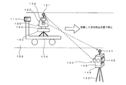
- FIG. 1 shows a road surface 100, a carriage 110 movable on the road surface 100, an automatic leveling table 120 installed on the carriage 110, and a laser scanner 130 installed on the automatic leveling table 120.
- the target of the laser scan is not particularly limited.
- the ground or slope in a civil engineering work site the wall of a tunnel, the outer surface or the inner surface of a building ( It is also possible to perform laser scanning for indoor wall surfaces and the like.
- the dolly 110 is movable on the road surface 100. Movement is performed manually by manual power. It is also possible to move the carriage 110 by the power of a motor or the like.
- the carriage 110 is stopped at a predetermined position, and in that state, laser scanning is performed on the road surface 100 or the wall surface or the ceiling in the case of a tunnel by the laser scanner 130. With this laser scan, it is confirmed that the road surface is flat or sloped, and if the tunnel is tunneled, the inside displacement or the like. In the case of indoors, confirmation of the present frame and interior is performed.
- the accuracy of the external positioning elements (position and orientation) of the laser scanner at the time of the laser scan is important.
- the effective range is about 30 m at maximum, and it is necessary to stop a trolley
- the above description of the effective range of the laser scanning light is an example, and in fact depends on the specifications of the laser scanner, the incident angle of the laser light to the object, the condition of the object, etc. Yes.
- the TS (total station) 140 is used to guide the laser scanner 130 to the stop position and to accurately specify the position. Further, by measuring the position of the TS 140 by the laser scanner 130, the external orientation element of the laser scanner 130 is specified with high accuracy.
- the all-round reflection prism 131 is fixed to the laser scanner 130, and the all-round reflection prism 141 is fixed to the TS 140.
- the all-round reflecting prisms 131 and 141 have optical characteristics that reflect incident light by changing its direction by 180 degrees in the direction of the entire circumference. If the stop position of the laser scanner 130 is predetermined, the information is stored in the terminal 111. In addition, it is also possible to use a spherical target, a reflecting prism which is not total reflection, and various kinds of targets used for surveying instead of the total reflection prism.
- the TS 140 installed at a known position tracks the all-round reflecting prism 131.
- the movement path of the laser scanner 130 (all-round reflection prism 131) is accurately measured by the positioning function provided in the TS 140, and the data is sent to the terminal 111.
- Data of a predetermined stop position is input to the terminal 111, and guidance information to the stop position of the carriage 110 is displayed on the terminal 111.
- the terminal 111 outputs a notification signal (guide information, notification display, notification sound, etc.). As a result, the carriage 110 can be stopped at a predetermined stop position.
- the laser scanner 130 is leveled by the automatic leveling table 120, and then the precise measurement of the total circumferential reflection prism 141 by the TS 140 is performed.
- the positioning of the all-round reflecting prism 141 is performed by the target (reflection prism) positioning function of the laser scanner 130.
- the position of the all-round reflection prism 141 in the absolute coordinate system is known, and by performing positioning of the all-round reflection prism 141 viewed from the laser scanner 130, the direction and distance of the all-round reflection prism 141 viewed from the laser scanner 130 are I understand. Thereby, the external orientation element (posture) in the absolute coordinate system of the laser scanner 130 is specified. Further, the position of the laser scanner 130 is accurately measured by the TS 140 after the leveling process as described above.
- laser scanning of the road surface 100 by the laser scanner 130 is performed to obtain laser scan data.
- the carriage 110 is moved to the next stop position. The above processing is repeated from the first stop position ⁇ the second stop position ⁇ ... The nth stop position, and the laser scan on the road surface 100 is performed.
- the stop position of the laser scanner 130 is accurately identified by the TS 140. This process is performed after the laser scanner 130 is leveled, and since the positioning accuracy of the TS 140 is high, the stop position of the laser scanner 130 can be accurately determined.
- a precise external orientation element of the laser scanner 130 at the stop position is determined. be able to. Therefore, accurate laser scan data can be obtained.
- processing guidance processing
- processing related to notification of the stop position by the TS 140 is automatically performed, high work efficiency can be obtained.
- the all-round prism 141 from the laser scanner 130, it is possible to obtain an external positioning element of the laser scanner 130 at the stop position.
- Capture, tracking, and positioning of the omnidirectional reflection prism by the TS 140 and the laser scanner 130 can be performed automatically. Thus, the entire work can be performed with high efficiency.
- the TS 140 uses a model available on the market.
- the TS is described in JP-A-2009-229192 and JP-A-2012-20282.
- the base portion 144 fixed on the tripod 143, the horizontal rotation portion 142 capable of horizontal rotation on the base portion 144, and the vertical rotation portion 142 are capable of vertical rotation (elevation angle change and depression angle change).
- a vertically rotating portion 145 and a full circumference reflecting prism 141 fixed to the upper portion of the horizontal rotating portion 142 are provided.
- FIG. 2 shows a TS140 block diagram (configuration diagram).
- Horizontal rotation of the horizontal rotation part 142 of FIG. 1 is performed by the horizontal rotation motor 15 driven by the horizontal drive part 15a of FIG.
- the horizontal rotation angle of the horizontal rotation unit 142 is detected by the horizontal angle encoder 16, and the angle data is output from the horizontal angle measurement unit 16a.
- the rotation of the vertical rotation unit 145 is performed by the vertical rotation motor 18 driven by the vertical drive unit 18 a.
- the rotation angle of the vertical rotation unit 145 is detected by the vertical angle encoder 19, and the angle measurement unit 19 outputs the angle data.
- the all-round reflection prism 131 disposed on the laser scanner 130 is used as a target to be measured by the TS 140.
- tracking light is emitted from the tracking light irradiator 42 to the all-round reflecting prism 131, and the reflected light is received by the tracking light receiver 43.
- the tracking light is irradiated within a certain range, and the horizontal rotation angle of the horizontal rotation portion 142 and the vertical angle of the vertical rotation portion 145 are adjusted so that the all-round reflection prism 131 is positioned at the center of the irradiation range.
- Measurement of the distance from the TS 140 to the all-round reflection prism 131 is performed by the distance measurement light emitted from the distance measurement light irradiator 50.
- the distance measuring light is pulse laser light, and is divided into two by an optical system (not shown), one of which is guided to a reference light path of a known distance provided in the TS 140 as a reference light and the other is It is irradiated.
- the distance measuring light reflected from the all-round reflecting prism 131 is received by the distance measuring light receiving unit 51.
- the reference light is also received by the distance measurement light receiving unit 51.
- the direction of the optical axis of the distance measurement light at the time of the above distance measurement is measured by the horizontal angle encoder 16 and the vertical angle encoder 19. From the distance and direction to the all-round reflection prism 131, positioning of the all-round reflection prism 131 is performed with reference to the TS 140. The calculation concerning this positioning is performed by the control calculation unit 60.
- the control calculation unit 60 is hardware that functions as a computer, and performs calculation related to the operation control and operation of the TS 140 in addition to the calculation related to the positioning of the above-mentioned all-round reflection prism.
- a target device 135 provided with an all-round reflection prism 131.
- the control in this case is described in Japanese Patent Laid-Open No. 2009-229192.
- a fan-shaped laser beam shaped into a fan-shaped beam is emitted from the fan-shaped laser beam irradiation unit 13.
- the irradiation light is irradiated while being scanned in the horizontal direction, and is received by the fan-shaped laser light receiver 6 of the target device 135.
- the fan-shaped laser beam has an N-shape or a W-shape as viewed from the optical axis direction, and the elevation angle from the TS 140 can be calculated from the light reception timing. This calculation is performed by the control calculation unit 62, and the result and the previous light reception time are stored in the storage unit 70.
- the previous elevation angle and the light reception time are transmitted from the wireless communication unit 63 to the wireless communication unit 64 of the TS 140, and based on the contents, the TS 140 calculates the direction of the target device 142 and directs the optical axis to the direction of the target device 135. Turn. As a result, general collimation of the all-round reflection prism 131 of the target device 135 is performed, and thereafter, collimation of the all-round reflection prism 131 by tracking light is performed, and positioning of the all-round reflection prism 131 by distance measurement light is further performed. Is done.
- the TS 140 includes an operation unit 65, a storage unit 61, a wireless communication unit 64, and a camera 52.
- the operation unit 65 includes a display that displays various buttons, switches, and various information for operating the TS 140.
- the storage unit 61 stores various data and an operation program related to the operation of the TS 140.
- the wireless communication unit 64 performs communication with the terminal 111 and the laser scanner 130 and communication with other external devices.
- the camera 52 has the same optical axis as the distance measurement light, and performs moving image shooting of the distance measurement target.
- the laser scanner 130 includes a main unit 132 and an optical unit 133 which are horizontally rotatable with respect to the base unit 134.
- a rotating mirror capable of vertical rotation is disposed in the optical unit 133.
- the distance measuring light from the distance measuring light irradiator 50 (see FIG. 3) disposed in the main body 132 is irradiated on the above-mentioned rotating mirror which vertically rotates. Also, the distance measuring light reflected from the object is reflected by the rotating mirror, and is received by the distance measuring light receiving unit 51 disposed in the main body 132.
- the distance measuring light is continuously pulse irradiated to the rotating mirror, and the laser with respect to the surroundings (or to a specific range) by the laser scanner 130 A scan is performed.
- the laser scanning in the laser scanner 130 is also laser positioning based on the same principle as that of the TS 140 when viewed with one pulse, but the TS 140 performs positioning by aiming at each point, whereas the laser scanner 130 While scanning at a speed of 10 points or more, positioning of the scan point is performed.
- laser scanning a plurality of distance measurement lights are simultaneously irradiated, and positioning of a plurality of points is performed simultaneously.
- the laser scanner is described in, for example, JP-A-2010-151682, JP-A-2008-268004, and US Pat. No. 8,767,190.
- US 2015-0293224 describes a laser scanner which switches scanning directions electronically.
- the laser scanner 130 has a positioning function targeting a reflecting prism.
- the reflection prism in this example, the full circumference reflection prism 141 of the TS 140
- This function is performed using the target (reflecting prism) capturing function similar to that of TS130.
- a laser scan with an increased scan density in the vicinity of the reflecting prism is performed.
- positioning data of the reflecting prism is extracted from the scan data.
- the terminal 111 is fixed to the carriage 110.
- the terminal 111 is fixed at a position where an operator pushing the carriage 111 can easily view and operate.
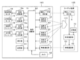
- the block diagram of the terminal 111 is shown in FIG.
- the terminal 111 functions as a controller of the TS 140, a notification device of the stop position of the carriage 110 (laser scanner 130), and a device for calculating the external positioning element (posture) of the laser scanner 130 at the stop position.
- the terminal 111 is hardware that functions as a computer, and is configured of a PC (personal computer), a tablet, a smartphone, or dedicated hardware that can perform the processing described below.
- the terminal 111 includes hardware and functions provided in a display device such as a liquid crystal display, an operation interface such as a numeric keypad and a touch panel display, a communication device, and the like such as a normal PC or tablet.
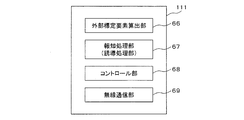
- the terminal 111 includes an external determination element calculator 66, a notification processor (guide processor) 67, and a controller 68 as functional units. These functional units are realized by installing dedicated application software in the terminal 111 and executing the software by the CPU of the terminal 111. In addition, the form which comprises an arithmetic circuit for exclusive use which performs the function mentioned above by FPGA etc. is also possible.
- the external positioning element calculation unit 66 calculates the external positioning element (in particular, the data of the attitude) of the laser scanner 130 based on the positioning data of the all-round reflection prism 141 performed by the laser scanner 130.
- the position of the laser scanner 130 at the stop position is specified by positioning using the TS 140, and the position data is received by the wireless communication unit 69.
- the attitude of the laser scanner 130 can be obtained as follows.
- the laser scanner 130 measures the position of the all-round reflection prism 141. At this time, the direction of the all-round reflection prism 141 viewed from the laser scanner 130 is obtained. Thereby, a directional line from the position of the laser scanner 130 to the position of the TS 140 (the position of the reflecting prism 141) is obtained.
- the horizontal angle shall be measured clockwise with respect to north.
- the direction of the above-mentioned direction line is 45 ° (the direction of the northeast).
- the relationship between the reference direction of the horizontal angle in the laser scanner 130 and the direction of the direction line is obtained.
- the value in the absolute coordinate system of the reference direction of the horizontal angle of the laser scanner 130 at the position is known.
- the laser scanner 130 secures the level by the function of the automatic leveling table 120, if the reference of the horizontal angle can be determined, the attitude is determined.
- the attitude of the laser scanner 130 at the specific stop position is calculated.
- the above processing is performed by the external orientation element calculator 66.
- the external orientation factor calculator 66 may be disposed on the laser scanner 130 side or the TS 140 side. It is also possible to calculate the external orientation factor of the laser scanner 130 with a device such as a server that is located at a remote location.
- the notification processing unit 67 is processing related to guiding the carriage 110 to a predetermined stop position, and when the carriage 110 (laser scanner 130) approaches or reaches the stop position, the display unit of the terminal 111 And a process of generating an alarm sound.
- the notification processing unit 67 is an example of a guiding device that guides the carriage 110 to the stop position.
- the notification processing unit 67 performs processing of displaying on the display unit of the terminal 111 (for example, a liquid crystal display device of a tablet) an arrow indicating the direction from the current location to the planned stop position and the distance to that. This process can be considered as a process of notifying information on the stop position as image information.
- These notification processes are performed based on the difference between the position data of the predetermined stop position and the position data of the laser scanner 130 determined by the TS 140. For example, the direction and distance to the next stop position are calculated in the terminal 111, and the content is displayed on the display unit of the terminal 111.
- the control unit 68 performs operation control (remote control) of the laser scanner 130 and the TS 140.
- the terminal 111 further includes a wireless communication unit 69.
- the wireless communication unit 69 communicates with the laser scanner 130 and the TS 140 and with other devices.
- FIG. 5 is a flow chart showing an example of the procedure of processing executed by the system of FIG.
- a program for executing the process of FIG. 5 is installed in the terminal 111 and executed by the CPU of the terminal 111. It is also possible to store the program in the storage unit 61 of the TS 140 or the laser scanner 130 or an external suitable storage medium.
- the operation of the laser scanner 130 and the TS 140 is remotely controlled by the terminal 111.
- the control in FIG. 5 may be performed by the laser scanner 130 or the TS 140, or may be performed by a server installed at a remote place.
- a laser scan using the laser scanner 130 is performed to check whether the surface condition (flatness or inclination) of the surface of the road surface 100 after the paving work satisfies the specified specifications.
- a laser scanner 130 provided with the all-round reflection prism 131 and a TS 140 provided with the all-round reflection prism 141 are prepared. Relationship between the optical origin (reflection point) of the all-round reflection prism 131 and the optical origin (position of the origin of the position calculation of the scanning point) of the laser scanner 130, the optical origin of the all-round reflection prism 141 and the optical origin of the TS 140 (for positioning The relationship with the origin is previously acquired as known data.
- the position (optical origin) of the laser scanner 130 is specified by performing positioning with the all-round reflecting prism 131 as a target, and the position of the TS 140 is measured by performing positioning with the all-round reflecting prism 141 as a target. (Optical origin) is identified.
- data of the stop position on the road surface 100 is input in advance to the TS 140.
- the effective range of the laser scan on the road surface is estimated to be 30 m, and the stop position of the carriage 110 is set every 20 m in consideration of the overlapping portion.
- the stop position is at the center in the width direction of the road.
- the stop interval is set on a case-by-case basis in relation to the effective range of scan laser light and the scan density, and is set according to the scan target.
- bogie 110 preset on the road surface 100 is marked.
- the TS 140 is installed at a position whose position on the absolute coordinate system is known (step S101). Further, the attitude (azimuth angle) of the TS 140 at this installation position is specified. This is the same as the operation of specifying an external orientation element at the time of installation of a TS (total station) which is usually performed.
- the absolute coordinate system is, for example, a world coordinate system used in GNSS, and is a coordinate system whose position is specified by latitude, longitude, and altitude from the average sea level. The specification of the position is performed, for example, by relative positioning using GNSS. Further, the TS 140 may be installed at a point whose position is specified in advance. As a coordinate system, it is also possible to use a local coordinate system set in the field.
- step S102 the full circumference reflecting prism 131 of the laser scanner 130 on the carriage 110 is captured by the TS 140 (step S102). This is performed by manual collimation, automatic collimation by the target search function of the TS 140, or a combination of approximate collimation and automatic collimation by manual operation.
- the dolly is manually pushed and moved toward the first stop position.
- capturing and positioning of the all-round reflecting prism 131 by the TS 140 are continuously performed.
- a terminal 111 serving as a controller of the TS 140 is fixed to the carriage 110 (a person pushing the carriage 110 may be in hand).
- the direction and distance of the target stop position are displayed on this terminal 111, and guidance of the carriage 110 is performed (step S103). This display is created based on the positioning data of the whole circumference prism 131 by the TS 140 and the position data of the stop position set in advance.
- the operator pushing the carriage 110 pushes the carriage 110 to the stop position while watching the display displayed on the terminal 111.
- the distance to the stop position in the display of the terminal 111 becomes 0, and a notification display notifying that effect is displayed, and a notification sound is emitted from the terminal 111.
- the inclination of the laser scanner 130 is corrected so that the vertical axis of the laser scanner 130 coincides with the vertical direction using the automatic standardizing function of the automatic leveling table 120 (step S104).
- the automatic leveling table 120 a type in which the inclination is detected by various inclination sensors (for example, a method of optically detecting a bubble or the like) and the inclination is adjusted by an actuator or the like based thereon is used.
- the technology related to the leveling table is described, for example, in Japanese Patent Laid-Open No. 2009-14368. A mode is also possible in which leveling is performed not manually but manually or semi-automatically.
- step S105 positioning of the all-round reflection prism 131 fixed to the laser scanner 130 by the TS 140 is performed.
- the positioning data of the all-round reflection prism 131 is sent to the terminal 111.
- the positioning of the laser scanner 130 is performed by measuring the all-round reflection prism 131. The same applies to the all-round reflection prism 141 and the TS 140.
- step S106 positioning of the all-round reflection prism 141 (TS 140) is performed using the laser scanner 130 whose position is accurately specified.
- the positioning data of the all-round reflection prism 141 is sent to the terminal 111.
- an external orientation element of the laser scanner 130 is calculated based on the position of the laser scanner 130 specified on the absolute coordinate system and the position of the TS 140 (step S107).
- the position in the external orientation element of the laser scanner 130 is positioned by the TS 140, and the positioning data is received by the terminal 111. Therefore, the attitude of the laser scanner 130 is calculated here. This process is performed by the external orientation element calculator 66 of the terminal 111.
- step S108 laser scanning of the road surface 100 using the laser scanner 130 is performed.
- the laser scan data of the road surface 100 can be obtained on an absolute coordinate system.
- step S103 When the laser scanning of the road surface 100 at the stop position guided in step S103 is completed, the process returns to the previous step of step S103, movement by guidance by the TS 140 to the next stop position is performed, and the processing from step 104 onward is repeated. . In this way, the movement to a plurality of preset stop positions and the cycle of the laser scanning after stopping there are repeated to acquire the laser scanning data of the road surface.
- the TS 140 guides the carriage 110 to a predetermined stop position and positions the laser scanner 130 at the stop position. Further, the external positioning element of the laser scanner 130 at the stop position is calculated by the positioning of the all-round reflection prism 141 by the laser scanner 130. At this time, there is no need for a person other than pushing and moving the carriage 110, and high work efficiency can be obtained.
- a TS it is also possible to use a TS to specify the position of a part of a plurality of predetermined planned stop positions.
- specification of the stop position without using TS is performed by shape matching.
- Shape matching is a technology for tracking changes in the movement path and external orientation factor of a laser scanner by laser scanning on overlapping regions performed from two different points.
- the TS 140 may be used to specify the first and last planned stop positions, and the other planned stop positions may be specified using shape matching described above.
- the stop position of the carriage 110 is specified using the principle of FIG. 1 and the laser scanner using the above shape matching is used otherwise.
- the planned stop position is specified by the position specifying process 130.
- the laser is based on the positioning data by the laser scanner 130 mounted on the carriage 110 and provided with the all-round reflection prism 131 and the positioning data by the total station 140 fixed on the ground and provided with the all-round reflection prism 141
- the guidance processing for guiding the carriage 110 to a predetermined stop position is performed.
- the positioning data by the laser scanner 130 is the positioning data of the all-round reflecting prism 141, and the total station
- the positioning data by 140 is Content is a positioning data peripheral reflecting prism 131 is disclosed.
- FIG. 2 An example of laser scanning of the inner wall (side wall and ceiling) of a tunnel is shown in FIG.
- the TS 140 is installed in the tunnel, and laser scanning of the inner wall of the tunnel is performed by the laser scanner 130 mounted on the carriage 110.
- the process of FIG. 5 is performed inside the tunnel.
- laser scanning of the road surface is also possible.
- the present invention can be used as a technique for alternately moving and stopping and performing laser scanning at the time of stopping.
Abstract
[Problem] To achieve high work efficiency in a technology in which a laser scanner is mounted to a moving body, movement and stoppage are alternately performed, and laser scanning is performed during stoppage. [Solution] A terminal 111 is provided with: an external orientation element calculation unit which calculates, on the basis of positioning data from a laser scanner 130 which is mounted to a truck 110, and provided with an all-round reflection prism 131, and positioning data from a total station 140 which is fixed on the ground, and provided with an all-round reflection prism 141, external orientation elements of the laser scanner 130; and a guidance processing unit which performs guidance processing for guiding the truck 110 to predetermined stop positions, on the basis of the positioning data of all-round reflection prism 131 from the total station 140. In the calculation of the external orientation elements of the laser scanner 130, the positioning data from the laser scanner 130 is the positioning data of all-round reflection prism 141, and the positioning data from the total station 140 is the positioning data of all-round reflection prism 131.
Description
本発明は、レーザースキャナを用いた測量に関する。
The present invention relates to surveying using a laser scanner.
台車等にレーザースキャナ等の測量装置を載せ、移動させながら測量を行う技術が知られている(例えば、特許文献1~3を参照)。
There is known a technology for carrying out surveying while moving a surveying instrument such as a laser scanner mounted on a carriage or the like (see, for example, Patent Documents 1 to 3).
台車にレーザースキャナを搭載し、台車の移動と停止を交互に行ない、停止時にレーザースキャナによる測量を行う場合、台車の停止位置の制御が重要となる。台車の停止位置が適切でないと、スキャンの重複が多くなり測量作業の無駄が増大する、あるいはスキャン範囲に隙間ができ、データの不足が発生する。よって、測量作業の効率化を追求する場合、台車の停止位置の制御が重要となる。
When a laser scanner is mounted on a carriage, movement and stop of the carriage are alternately performed, and measurement is performed by the laser scanner at stop, control of the stop position of the carriage becomes important. If the stop position of the carriage is not appropriate, scanning duplication will increase and waste of surveying work will increase, or gaps in the scan range will occur, resulting in data shortage. Therefore, control of the stop position of a trolley | bogie becomes important when pursuing efficiency improvement of surveying work.
このような背景において、本発明は、移動体にレーザースキャナを搭載し、移動と停止を交互に行ない、停止時にレーザースキャンを行う技術において、高い作業効率が得られる技術の提供を目的とする。
In such a background, the present invention aims to provide a technique that can achieve high working efficiency in a technique of mounting a laser scanner on a moving body, alternately performing movement and stopping, and performing laser scanning at the time of stopping.
請求項1に記載の発明は、移動体に搭載され、第1の反射プリズムを備えたレーザースキャナによる測位データと、地上に固定され、第2の反射プリズムを備えたトータルステーションによる測位データとに基づき前記レーザースキャナの外部標定要素の算出を行う外部標定要素算出部と、前記トータルステーションによる前記第1の反射プリズムの測位データに基づき、予め定められた停止位置に前記移動体を誘導するための誘導処理を行う誘導処理部とを備えた測量装置であって、前記レーザースキャナの前記外部標定要素の算出において、前記レーザースキャナによる前記測位データは、前記第2の反射プリズムの測位データであり、前記トータルステーションによる前記測位データは、前記第1の反射プリズムの測位データである測量装置である。
The invention according to claim 1 is based on positioning data by a laser scanner equipped with a first reflecting prism, and positioning data by a total station fixed to the ground and comprising a second reflecting prism. A guidance process for guiding the moving body to a predetermined stop position based on an external determination element calculation unit that calculates an external determination element of the laser scanner and positioning data of the first reflecting prism by the total station A survey processing device including a guidance processing unit for performing the calculation, in the calculation of the external orientation element of the laser scanner, the positioning data by the laser scanner is positioning data of the second reflecting prism, and the total station Said positioning data according to is the positioning data of said first reflecting prism It is the amount apparatus.
請求項2に記載の発明は、請求項1に記載の測量装置と、前記レーザースキャナの整準を行うための整準装置とを備える測量システムである。請求項3に記載の発明は、請求項2に記載の発明において、前記整準装置による前記レーザースキャナの整準動作の後、前記トータルステーションによる前記第1の反射プリズムの測位が行われることを特徴とする。
The invention according to claim 2 is a surveying system comprising the surveying instrument according to claim 1 and a leveling device for leveling the laser scanner. The invention according to claim 3 is characterized in that, in the invention according to claim 2, the positioning of the first reflecting prism by the total station is performed after the leveling operation of the laser scanner by the leveling device. I assume.
請求項4に記載の発明は、移動体に搭載され、第1の反射プリズムを備えたレーザースキャナによる測位データと、地上に固定され、第2の反射プリズムを備えたトータルステーションによる測位データとに基づく前記レーザースキャナの外部標定要素の算出と、前記トータルステーションによる前記第1の反射プリズムの測位データに基づき、予め定められた停止位置に前記移動体を誘導する誘導処理とを行う測量方法であり、前記レーザースキャナの前記外部標定要素の算出は、前記トータルステーションによる前記第1の反射プリズムの測位データと、前記レーザースキャナによる前記第2の反射プリズムの測位データとに基づき行われる測量方法である。
The invention according to claim 4 is based on positioning data by a laser scanner equipped with a first reflecting prism, and positioning data by a total station fixed to the ground and comprising a second reflecting prism. A surveying method for performing guidance processing for guiding the moving body to a predetermined stop position based on calculation of external orientation elements of the laser scanner and positioning data of the first reflecting prism by the total station, The calculation of the external orientation element of the laser scanner is a surveying method performed based on the positioning data of the first reflecting prism by the total station and the positioning data of the second reflecting prism by the laser scanner.
請求項5に記載の発明は、コンピュータに読み取らせて実行させるプログラムであって、コンピュータに、移動体に搭載され、第1の反射プリズムを備えたレーザースキャナによる測位データと、地上に固定され、第2の反射プリズムを備えたトータルステーションによる測位データとに基づく前記レーザースキャナの外部標定要素の算出と、前記トータルステーションによる前記第1の反射プリズムの測位データに基づき、予め定められた停止位置へ前記移動体を誘導する誘導処理とを実行させ、前記レーザースキャナの前記外部標定要素の算出は、前記トータルステーションによる前記第1の反射プリズムの測位データと、前記レーザースキャナによる前記第2の反射プリズムの測位データとに基づき行われる測量用プログラムである。
The invention according to claim 5 is a program that causes a computer to read and execute the program, wherein the computer is mounted on a moving body and fixed on the ground with positioning data by a laser scanner provided with a first reflecting prism, The movement to a predetermined stop position based on the calculation of the external positioning element of the laser scanner based on the positioning data by the total station provided with the second reflecting prism and the positioning data of the first reflecting prism by the total station The guidance processing for guiding the body is performed, and the calculation of the external orientation element of the laser scanner is performed by using the positioning data of the first reflecting prism by the total station and the positioning data of the second reflecting prism by the laser scanner. Program for surveying based on
本発明によれば、移動体にレーザースキャナを搭載し、移動と停止を交互に行ない、停止時にレーザースキャンを行う技術において、高い作業効率が得られる。
According to the present invention, high work efficiency can be obtained in the technology of mounting a laser scanner on a moving body, alternately performing movement and stopping, and performing laser scanning at the time of stopping.
1.第1の実施形態
(概要)
図1に発明を利用した実施形態の概要を示す。図1には、路面100、路面100上で移動可能な台車110、台車110上の設置された自動整準台120、自動整準台120の上に設置されたレーザースキャナ130が示されている。ここでは、路面を対象にレーザースキャンを行う場合の例を示すが、レーザースキャンの対象は、特に限定されず、例えば、土木工事現場における地面や法面、トンネルの壁面、建物の外面または内面(室内の壁面)等を対象にレーザースキャンを行うことも可能である。 1. First embodiment (outline)
FIG. 1 shows an outline of an embodiment using the invention. FIG. 1 shows aroad surface 100, a carriage 110 movable on the road surface 100, an automatic leveling table 120 installed on the carriage 110, and a laser scanner 130 installed on the automatic leveling table 120. . Here, an example of performing a laser scan on a road surface is shown, but the target of the laser scan is not particularly limited. For example, the ground or slope in a civil engineering work site, the wall of a tunnel, the outer surface or the inner surface of a building ( It is also possible to perform laser scanning for indoor wall surfaces and the like.
(概要)
図1に発明を利用した実施形態の概要を示す。図1には、路面100、路面100上で移動可能な台車110、台車110上の設置された自動整準台120、自動整準台120の上に設置されたレーザースキャナ130が示されている。ここでは、路面を対象にレーザースキャンを行う場合の例を示すが、レーザースキャンの対象は、特に限定されず、例えば、土木工事現場における地面や法面、トンネルの壁面、建物の外面または内面(室内の壁面)等を対象にレーザースキャンを行うことも可能である。 1. First embodiment (outline)
FIG. 1 shows an outline of an embodiment using the invention. FIG. 1 shows a
台車110は、路面100上を移動可能である。移動は、手押しによる人力で行われる。台車110の移動をモータ等の動力で行うことも可能である。台車110は、所定の位置で停止し、その状態でレーザースキャナ130による路面100やトンネル内の場合は壁面や天井を対象としたレーザースキャンが行なわれる。このレーザースキャンにより、路面の場合は平坦性や傾斜等、トンネルの場合は内空変位等の確認が行われる。また、室内の場合は、現状の躯体や内装の確認が行われる。
The dolly 110 is movable on the road surface 100. Movement is performed manually by manual power. It is also possible to move the carriage 110 by the power of a motor or the like. The carriage 110 is stopped at a predetermined position, and in that state, laser scanning is performed on the road surface 100 or the wall surface or the ceiling in the case of a tunnel by the laser scanner 130. With this laser scan, it is confirmed that the road surface is flat or sloped, and if the tunnel is tunneled, the inside displacement or the like. In the case of indoors, confirmation of the present frame and interior is performed.
上記のレーザースキャンの精度を求める場合、レーザースキャン時におけるレーザースキャナの外部標定要素(位置と姿勢)の精度が重要となる。また、路面をレーザースキャンの対象とする場合、路面へのレーザー光の入射角の問題から、有効射程が最大で30m程度であり、台車は20m毎程度に停車させる必要がある。このため、作業効率を高める上で台車110の静止位置を正確に把握することが重要となる。なお、上記のレーザースキャン光の有効射程の話は、一例であり、実際には、レーザースキャナの仕様、対象物へのレーザー光の入射角度、対象物の状態等によって左右され、多様な場合が有り得る。
In order to determine the accuracy of the above laser scan, the accuracy of the external positioning elements (position and orientation) of the laser scanner at the time of the laser scan is important. Moreover, when making a road surface into the object of a laser scan, the effective range is about 30 m at maximum, and it is necessary to stop a trolley | bogie about every 20 m from the problem of the incident angle of the laser beam to a road surface. For this reason, it is important to accurately grasp the stationary position of the carriage 110 in order to enhance the work efficiency. Note that the above description of the effective range of the laser scanning light is an example, and in fact depends on the specifications of the laser scanner, the incident angle of the laser light to the object, the condition of the object, etc. Yes.
本実施形態では、TS(トータルステーション)140を用いて、レーザースキャナ130を停止位置に誘導し、またその位置を正確に特定する。また、レーザースキャナ130によりTS140の位置を測位することで、レーザースキャナ130の外部標定要素を高精度に特定する。
In the present embodiment, the TS (total station) 140 is used to guide the laser scanner 130 to the stop position and to accurately specify the position. Further, by measuring the position of the TS 140 by the laser scanner 130, the external orientation element of the laser scanner 130 is specified with high accuracy.
以下、簡単に原理を説明する(詳細は後述する)。レーザースキャナ130には、全周反射プリズム131が固定され、TS140には、全周反射プリズム141が固定されている。全周反射プリズム131,141は、全周の方向において、入射した光を180°向きを変えて反射する光学特性を有する。レーザースキャナ130の停止位置は予め定められている場合は、その情報は端末111に記憶されている。なお、全周反射プリズムの代わりに球形ターゲットや全周反射でない反射プリズム、更には測量に用いられる各種のターゲットを用いることも可能である。
The principle will be briefly described below (details will be described later). The all-round reflection prism 131 is fixed to the laser scanner 130, and the all-round reflection prism 141 is fixed to the TS 140. The all-round reflecting prisms 131 and 141 have optical characteristics that reflect incident light by changing its direction by 180 degrees in the direction of the entire circumference. If the stop position of the laser scanner 130 is predetermined, the information is stored in the terminal 111. In addition, it is also possible to use a spherical target, a reflecting prism which is not total reflection, and various kinds of targets used for surveying instead of the total reflection prism.
路面100上で台車110を人力で移動させつつ、既知の位置に設置されたTS140により、全周反射プリズム131を追跡する。レーザースキャナ130(全周反射プリズム131)の移動経路は、TS140が備えた測位機能により正確に計測され、そのデータは端末111に送られる。端末111には、予め定めた停止位置のデータが入力されており、端末111に台車110の停止位置への誘導情報が表示される。また台車110が予め定めた位置となると(またはその近くにくると)、端末111は、報知信号(誘導情報、報知表示、報知音等)を出力する。これにより、予め定めた停止位置に台車110を停止させることができる。
While moving the bogie 110 manually on the road surface 100, the TS 140 installed at a known position tracks the all-round reflecting prism 131. The movement path of the laser scanner 130 (all-round reflection prism 131) is accurately measured by the positioning function provided in the TS 140, and the data is sent to the terminal 111. Data of a predetermined stop position is input to the terminal 111, and guidance information to the stop position of the carriage 110 is displayed on the terminal 111. When the carriage 110 reaches a predetermined position (or comes close thereto), the terminal 111 outputs a notification signal (guide information, notification display, notification sound, etc.). As a result, the carriage 110 can be stopped at a predetermined stop position.
予め定めた停止位置で台車110が停止したら、自動整準台120によるレーザースキャナ130の整準を行い、その後TS140による全周反射プリズム141の改めての精密な位置の測定を行う。また、レーザースキャナ130の整準処理の後、レーザースキャナ130が備えるターゲット(反射プリズム)測位機能により全周反射プリズム141の測位を行う。全周反射プリズム141の絶対座標系における位置は既知であり、レーザースキャナ130から見た全周反射プリズム141の測位を行うことで、レーザースキャナ130から見た全周反射プリズム141の方向と距離が判る。これにより、レーザースキャナ130の絶対座標系における外部標定要素(姿勢)が特定される。また、レーザースキャナ130の位置は、上記のように整準処理の後、TS140により正確に測位される。
When the carriage 110 stops at a predetermined stop position, the laser scanner 130 is leveled by the automatic leveling table 120, and then the precise measurement of the total circumferential reflection prism 141 by the TS 140 is performed. In addition, after the leveling process of the laser scanner 130, the positioning of the all-round reflecting prism 141 is performed by the target (reflection prism) positioning function of the laser scanner 130. The position of the all-round reflection prism 141 in the absolute coordinate system is known, and by performing positioning of the all-round reflection prism 141 viewed from the laser scanner 130, the direction and distance of the all-round reflection prism 141 viewed from the laser scanner 130 are I understand. Thereby, the external orientation element (posture) in the absolute coordinate system of the laser scanner 130 is specified. Further, the position of the laser scanner 130 is accurately measured by the TS 140 after the leveling process as described above.
停止位置におけるレーザースキャナ130の外部標定要素を特定したら、レーザースキャナ130による路面100に対するレーザースキャンが行なわれ、レーザースキャンデータを得る。このレーザースキャンの後、次の停止位置に台車110を移動させる。以上の処理が、第1の停止位置→第2の停止位置→・・・・第nの停止位置と繰り返され、路面100に対するレーザースキャンが行なわれる。
Once the external positioning elements of the laser scanner 130 at the stop position are identified, laser scanning of the road surface 100 by the laser scanner 130 is performed to obtain laser scan data. After this laser scan, the carriage 110 is moved to the next stop position. The above processing is repeated from the first stop position → the second stop position →... The nth stop position, and the laser scan on the road surface 100 is performed.
上記の方法によれば、まずTS140によるレーザースキャナ130の停止位置の正確な特定が行われる。この処理は、レーザースキャナ130の整準が行われた後に行なわれ、また、TS140の測位精度は高いので、レーザースキャナ130の停止位置を正確に定めることができる。また、整準が行われ、更に位置決めが正確に行われたレーザースキャナ130による全周反射プリズム141(TS140)の測位を行うことで、当該停止位置におけるレーザースキャナ130の精密な外部標定要素を求めることができる。このため、正確なレーザースキャンデータを得ることができる。また、TS140による停止位置の報知に係る処理(誘導処理)は自動で行われるので、高い作業効率が得られる。
According to the above method, first, the stop position of the laser scanner 130 is accurately identified by the TS 140. This process is performed after the laser scanner 130 is leveled, and since the positioning accuracy of the TS 140 is high, the stop position of the laser scanner 130 can be accurately determined. In addition, by performing positioning of the all-circumferential reflecting prism 141 (TS 140) by the laser scanner 130 which has been leveled and accurately positioned, a precise external orientation element of the laser scanner 130 at the stop position is determined. be able to. Therefore, accurate laser scan data can be obtained. In addition, since processing (guidance processing) related to notification of the stop position by the TS 140 is automatically performed, high work efficiency can be obtained.
また、レーザースキャナ130から全周プリズム141の測位を行うことで、停止位置におけるレーザースキャナ130の外部標定要素を求めることができる。
Further, by positioning the all-round prism 141 from the laser scanner 130, it is possible to obtain an external positioning element of the laser scanner 130 at the stop position.
TS140およびレーザースキャナ130による全周反射プリズムの捕捉、追尾、測位は、自動で行うことができる。よって、全体の作業を高い効率で行うことができる。
Capture, tracking, and positioning of the omnidirectional reflection prism by the TS 140 and the laser scanner 130 can be performed automatically. Thus, the entire work can be performed with high efficiency.
(TS(トータルステーション))
TS140は、市場で入手できる機種を用いている。TSについては、特開2009-229192号公報や特開2012-202821号公報に記載されている。TS140は、三脚143上に固定された基台部144、基台部144上に水平回転が可能な水平回転部142、水平回転部142に対して鉛直回転(仰角変化および俯角変化)が可能な鉛直回転部145、水平回転部142の上部に固定された全周反射プリズム141を備えている。 (TS (Total Station))
TheTS 140 uses a model available on the market. The TS is described in JP-A-2009-229192 and JP-A-2012-20282. The base portion 144 fixed on the tripod 143, the horizontal rotation portion 142 capable of horizontal rotation on the base portion 144, and the vertical rotation portion 142 are capable of vertical rotation (elevation angle change and depression angle change). A vertically rotating portion 145 and a full circumference reflecting prism 141 fixed to the upper portion of the horizontal rotating portion 142 are provided.
TS140は、市場で入手できる機種を用いている。TSについては、特開2009-229192号公報や特開2012-202821号公報に記載されている。TS140は、三脚143上に固定された基台部144、基台部144上に水平回転が可能な水平回転部142、水平回転部142に対して鉛直回転(仰角変化および俯角変化)が可能な鉛直回転部145、水平回転部142の上部に固定された全周反射プリズム141を備えている。 (TS (Total Station))
The
図2にTS140ブロック図(構成図)を示す。図1の水平回転部142の水平回転は、図2の水平駆動部15aにより駆動される水平回転モータ15により行われる。水平回転部142の水平回転の角度は、水平角エンコーダ16で検出され、水平測角部16aからその角度データが出力される。鉛直回転部145の回転は、鉛直駆動部18aにより駆動される鉛直回転モータ18により行われる。鉛直回転部145の回転角は、鉛直角エンコーダ19で検出され、鉛直測角部19からその角度データが出力される。
FIG. 2 shows a TS140 block diagram (configuration diagram). Horizontal rotation of the horizontal rotation part 142 of FIG. 1 is performed by the horizontal rotation motor 15 driven by the horizontal drive part 15a of FIG. The horizontal rotation angle of the horizontal rotation unit 142 is detected by the horizontal angle encoder 16, and the angle data is output from the horizontal angle measurement unit 16a. The rotation of the vertical rotation unit 145 is performed by the vertical rotation motor 18 driven by the vertical drive unit 18 a. The rotation angle of the vertical rotation unit 145 is detected by the vertical angle encoder 19, and the angle measurement unit 19 outputs the angle data.
この例では、TS140が測位するターゲットとしてレーザースキャナ130に配置した全周反射プリズム131が利用される。この場合、追尾光照射部42から追尾光が全周反射プリズム131に照射され、その反射光が追尾光受光部43で受光される。追尾光はある程度の範囲で照射され、その照射範囲の中心に全周反射プリズム131が位置するように水平回転部142の水平回転角と鉛直回転部145の鉛直角の調整が行われる。
In this example, the all-round reflection prism 131 disposed on the laser scanner 130 is used as a target to be measured by the TS 140. In this case, tracking light is emitted from the tracking light irradiator 42 to the all-round reflecting prism 131, and the reflected light is received by the tracking light receiver 43. The tracking light is irradiated within a certain range, and the horizontal rotation angle of the horizontal rotation portion 142 and the vertical angle of the vertical rotation portion 145 are adjusted so that the all-round reflection prism 131 is positioned at the center of the irradiation range.
TS140から全周反射プリズム131までの距離の計測が測距光照射部50から照射される測距光によって行われる。測距光は、パルスレーザー光であり、図示しない光学系で二分され、一方が基準光としてTS140内に設けられた図示しない距離が既知の基準光路に導かれ、他方が全周反射プリズム131に照射される。全周反射プリズム131から反射された測距光は、測距光受光部51で受光される。他方で、基準光も測距光受光部51で受光される。基準光と全周反射プリズム131から反射された測距光とは、光路長に差があり、測距光受光部51での検出タイミングに差が生じ、測距光受光部51からの出力信号に位相差が生じる。この位相差からTS140から全周反射プリズム131までの距離が算出される。
Measurement of the distance from the TS 140 to the all-round reflection prism 131 is performed by the distance measurement light emitted from the distance measurement light irradiator 50. The distance measuring light is pulse laser light, and is divided into two by an optical system (not shown), one of which is guided to a reference light path of a known distance provided in the TS 140 as a reference light and the other is It is irradiated. The distance measuring light reflected from the all-round reflecting prism 131 is received by the distance measuring light receiving unit 51. On the other hand, the reference light is also received by the distance measurement light receiving unit 51. There is a difference in the optical path length between the reference light and the distance measuring light reflected from the all-round reflecting prism 131, and a difference occurs in the detection timing in the distance measuring light receiving section 51. The output signal from the distance measuring light receiving section 51 Phase difference occurs. From this phase difference, the distance from the TS 140 to the all-round reflecting prism 131 is calculated.
上記の測距時における測距光の光軸の方向が水平角エンコーダ16および鉛直角エンコーダ19で測角される。全周反射プリズム131までの距離と方向とから、TS140を基準とした全周反射プリズム131の測位が行われる。この測位に係る演算は、制御演算部60で行なわれる。制御演算部60は、コンピュータとして機能するハードウェアであり、上記の全周反射プリズムの測位に係る演算の他にTS140の動作制御および動作に係る演算を行う。
The direction of the optical axis of the distance measurement light at the time of the above distance measurement is measured by the horizontal angle encoder 16 and the vertical angle encoder 19. From the distance and direction to the all-round reflection prism 131, positioning of the all-round reflection prism 131 is performed with reference to the TS 140. The calculation concerning this positioning is performed by the control calculation unit 60. The control calculation unit 60 is hardware that functions as a computer, and performs calculation related to the operation control and operation of the TS 140 in addition to the calculation related to the positioning of the above-mentioned all-round reflection prism.
全周反射プリズム131を備えたターゲット装置135を用いることもできる。この場合の制御については、特開2009-229192号公報に記載されている。例えばこの場合、扇状にビーム成形された扇状レーザー光が扇状レーザー光照射部13から照射される。この照射光は、水平方向に走査されながら照射され、ターゲット装置135の扇状レーザー光受光体6で受光される。扇状レーザー光は光軸方向から見てN字型やW字型を有しており、受光タイミングからTS140からの高低角が算出できる。この演算が制御演算部62で行なわれ、その結果と先の受光時刻が記憶部70に記憶される。
It is also possible to use a target device 135 provided with an all-round reflection prism 131. The control in this case is described in Japanese Patent Laid-Open No. 2009-229192. For example, in this case, a fan-shaped laser beam shaped into a fan-shaped beam is emitted from the fan-shaped laser beam irradiation unit 13. The irradiation light is irradiated while being scanned in the horizontal direction, and is received by the fan-shaped laser light receiver 6 of the target device 135. The fan-shaped laser beam has an N-shape or a W-shape as viewed from the optical axis direction, and the elevation angle from the TS 140 can be calculated from the light reception timing. This calculation is performed by the control calculation unit 62, and the result and the previous light reception time are stored in the storage unit 70.
先の高低角と受光時刻は、無線通信部63からTS140の無線通信部64に送信され、その内容に基づき、TS140では、ターゲット装置142の方向を算出し、光軸をターゲット装置135の方向に向ける。それによりターゲット装置135の全周反射プリズム131に対する概略の視準が行われ、その後は、追尾光による全周反射プリズム131の視準が行われ、更に測距光による全周反射プリズム131の測位が行われる。
The previous elevation angle and the light reception time are transmitted from the wireless communication unit 63 to the wireless communication unit 64 of the TS 140, and based on the contents, the TS 140 calculates the direction of the target device 142 and directs the optical axis to the direction of the target device 135. Turn. As a result, general collimation of the all-round reflection prism 131 of the target device 135 is performed, and thereafter, collimation of the all-round reflection prism 131 by tracking light is performed, and positioning of the all-round reflection prism 131 by distance measurement light is further performed. Is done.
TS140は、操作部65、記憶部61、無線通信部64、カメラ52を備えている。操作部65は、TS140を操作するための各種のボタン、スイッチ、各種の情報が表示されディスプレイを備える。記憶部61は、TS140の動作に係る各種のデータや動作プログラムを記憶する。無線通信部64は、端末111やレーザースキャナ130との間の通信、その他外部の機器との間との通信を行う。カメラ52は、測距光と同じ光軸を有し、測距対象の動画撮影を行う。
The TS 140 includes an operation unit 65, a storage unit 61, a wireless communication unit 64, and a camera 52. The operation unit 65 includes a display that displays various buttons, switches, and various information for operating the TS 140. The storage unit 61 stores various data and an operation program related to the operation of the TS 140. The wireless communication unit 64 performs communication with the terminal 111 and the laser scanner 130 and communication with other external devices. The camera 52 has the same optical axis as the distance measurement light, and performs moving image shooting of the distance measurement target.
(レーザースキャナ)
図3にレーザースキャナ130のブロック図を示す。装置の外観は異なるが、レーザースキャナ130の基本構成は、TS140と同じである。レーザースキャナ130では、基台部134に対して水平回転可能な本体部132と光学部133を備える。光学部133に鉛直回転可能な回転ミラーが配置されている。本体部132に配置された測距光照射部50(図3参照)からの測距光が鉛直回転する上記の回転ミラーに照射される。また対象物から反射した測距光がこの回転ミラーで反射され、本体部132に配置された測距光受光部51で受光される。 (Laser scanner)
A block diagram of thelaser scanner 130 is shown in FIG. Although the appearance of the device is different, the basic configuration of the laser scanner 130 is the same as that of the TS 140. The laser scanner 130 includes a main unit 132 and an optical unit 133 which are horizontally rotatable with respect to the base unit 134. A rotating mirror capable of vertical rotation is disposed in the optical unit 133. The distance measuring light from the distance measuring light irradiator 50 (see FIG. 3) disposed in the main body 132 is irradiated on the above-mentioned rotating mirror which vertically rotates. Also, the distance measuring light reflected from the object is reflected by the rotating mirror, and is received by the distance measuring light receiving unit 51 disposed in the main body 132.
図3にレーザースキャナ130のブロック図を示す。装置の外観は異なるが、レーザースキャナ130の基本構成は、TS140と同じである。レーザースキャナ130では、基台部134に対して水平回転可能な本体部132と光学部133を備える。光学部133に鉛直回転可能な回転ミラーが配置されている。本体部132に配置された測距光照射部50(図3参照)からの測距光が鉛直回転する上記の回転ミラーに照射される。また対象物から反射した測距光がこの回転ミラーで反射され、本体部132に配置された測距光受光部51で受光される。 (Laser scanner)
A block diagram of the
本体部132が水平回転し、且つ、光学部133内の回転ミラーが鉛直回転しつつ測距光が回転ミラーに対して連続パルス照射され、レーザースキャナ130による周囲に対する(あるいは特定の範囲に対する)レーザースキャンが行なわれる。
While the main body 132 is horizontally rotated and the rotating mirror in the optical unit 133 is vertically rotated, the distance measuring light is continuously pulse irradiated to the rotating mirror, and the laser with respect to the surroundings (or to a specific range) by the laser scanner 130 A scan is performed.
レーザースキャナ130におけるレーザースキャンも一つのパルスで見ると、TS140と同じ原理によるレーザー測位であるが、TS140が一点一点狙いを付けて測位を行うのに対して、レーザースキャナ130は、毎秒数十点以上の速度でスキャンしながらスキャン点の測位を行う。また、レーザースキャンでは、測距光は複数条同時に照射され、同時に複数の点の測位が行われる。レーザースキャナに関しては、特開2010-151682号公報、特開2008-268004号公報、米国特許8767190号公報等に記載されている。また、米国公開公報US2015-0293224号には、電子式にスキャン方向の切り替えを行うレーザースキャナについて記載されている。
The laser scanning in the laser scanner 130 is also laser positioning based on the same principle as that of the TS 140 when viewed with one pulse, but the TS 140 performs positioning by aiming at each point, whereas the laser scanner 130 While scanning at a speed of 10 points or more, positioning of the scan point is performed. In laser scanning, a plurality of distance measurement lights are simultaneously irradiated, and positioning of a plurality of points is performed simultaneously. The laser scanner is described in, for example, JP-A-2010-151682, JP-A-2008-268004, and US Pat. No. 8,767,190. US 2015-0293224 describes a laser scanner which switches scanning directions electronically.
レーザースキャナ130は、反射プリズムをターゲットした測位機能を有している。この機能では、まず反射プリズム(この例ではTS140の全周反射プリズム141)の視準を行う。この機能は、TS130と同様のターゲット(反射プリズム)の捕捉機能を用いて行われる。次に、当該反射プリズムの付近に対するスキャン密度を高めたレーザースキャンを行う。この際、反射プリズムからの反射光の強度が相対的に高いことを利用し、スキャンデータから反射プリズムの測位データを抽出する。
The laser scanner 130 has a positioning function targeting a reflecting prism. In this function, first, the reflection prism (in this example, the full circumference reflection prism 141 of the TS 140) is collimated. This function is performed using the target (reflecting prism) capturing function similar to that of TS130. Next, a laser scan with an increased scan density in the vicinity of the reflecting prism is performed. At this time, utilizing the fact that the intensity of the reflected light from the reflecting prism is relatively high, positioning data of the reflecting prism is extracted from the scan data.
端末111は、台車110に固定されている。端末111は、台車111を押す作業者が見易く、また操作し易い位置に固定されている。図4に端末111のブロック図を示す。端末111は、TS140のコントローラ、台車110(レーザースキャナ130)の停止位置の報知装置、および停止位置におけるレーザースキャナ130の外部標定要素(姿勢)を計算する装置として機能する。
The terminal 111 is fixed to the carriage 110. The terminal 111 is fixed at a position where an operator pushing the carriage 111 can easily view and operate. The block diagram of the terminal 111 is shown in FIG. The terminal 111 functions as a controller of the TS 140, a notification device of the stop position of the carriage 110 (laser scanner 130), and a device for calculating the external positioning element (posture) of the laser scanner 130 at the stop position.
端末111は、コンピュータとして機能するハードウェアであり、以下に説明する処理が可能なPC(パーソナルコンピュータ)、タブレット、スマートフォン、または専用のハードウェアにより構成されている。端末111は、液晶ディスプレイ等の表示装置、テンキーやタッチパネルディスプレイ等の操作インターフェース、通信装置等、通常のPCやタブレット等が備えるハードウェアおよび機能を備えている。
The terminal 111 is hardware that functions as a computer, and is configured of a PC (personal computer), a tablet, a smartphone, or dedicated hardware that can perform the processing described below. The terminal 111 includes hardware and functions provided in a display device such as a liquid crystal display, an operation interface such as a numeric keypad and a touch panel display, a communication device, and the like such as a normal PC or tablet.
端末111は、機能部として外部標定要素算出部66、報知処理部(誘導処理部)67、コントロール部68を備えている。これらの機能部は、専用のアプリケーションソフトを端末111にインストールし、端末111のCPUで実行することで実現される。なお、上述した機能を実行する専用の演算回路をFPGA等で構成する形態も可能である。
The terminal 111 includes an external determination element calculator 66, a notification processor (guide processor) 67, and a controller 68 as functional units. These functional units are realized by installing dedicated application software in the terminal 111 and executing the software by the CPU of the terminal 111. In addition, the form which comprises an arithmetic circuit for exclusive use which performs the function mentioned above by FPGA etc. is also possible.
外部標定要素算出部66は、レーザースキャナ130が行う全周反射プリズム141の測位データに基づき、レーザースキャナ130の外部標定要素(特にその姿勢のデータ)を算出する。
The external positioning element calculation unit 66 calculates the external positioning element (in particular, the data of the attitude) of the laser scanner 130 based on the positioning data of the all-round reflection prism 141 performed by the laser scanner 130.
以下、レーザースキャナ130の外部標定要素(特にその姿勢のデータ)を算出する方法について説明する。まず、停止位置におけるレーザースキャナ130の位置は、TS140を用いた測位により特定され、その位置データは、無線通信部69で受信されている。ここで、レーザースキャナ130の姿勢は以下のようにして求められる。
Hereinafter, a method of calculating an external measurement element (in particular, data of the posture) of the laser scanner 130 will be described. First, the position of the laser scanner 130 at the stop position is specified by positioning using the TS 140, and the position data is received by the wireless communication unit 69. Here, the attitude of the laser scanner 130 can be obtained as follows.
この場合、レーザースキャナ130により全周反射プリズム141の測位を行う。この際、レーザースキャナ130から見た全周反射プリズム141の方向が得られる。これにより、レーザースキャナ130の位置からTS140の位置(反射プリズム141の位置)への方向線が得られる。
In this case, the laser scanner 130 measures the position of the all-round reflection prism 141. At this time, the direction of the all-round reflection prism 141 viewed from the laser scanner 130 is obtained. Thereby, a directional line from the position of the laser scanner 130 to the position of the TS 140 (the position of the reflecting prism 141) is obtained.
ここで、水平角を考える。なお、水平角は北を基準として時計回り方向で計測するものとする。ここで、上記の方向線の方向が45°(北東の方向)であったとする。この場合、レーザースキャナ130における水平角の基準方向と上記の方向線の方向との関係が取得される。この結果、当該位置におけるレーザースキャナ130の水平角の基準方向の絶対座標系での値が判る。なお、レーザースキャナ130は、自動整準台120の機能により、水平が確保されるので、水平角の基準を確定できれば、その姿勢が確定する。こうして、特定の停止位置におけるレーザースキャナ130の姿勢が算出される。以上の処理が外部標定要素算出部66で行なわれる。
Now consider the horizontal angle. The horizontal angle shall be measured clockwise with respect to north. Here, it is assumed that the direction of the above-mentioned direction line is 45 ° (the direction of the northeast). In this case, the relationship between the reference direction of the horizontal angle in the laser scanner 130 and the direction of the direction line is obtained. As a result, the value in the absolute coordinate system of the reference direction of the horizontal angle of the laser scanner 130 at the position is known. In addition, since the laser scanner 130 secures the level by the function of the automatic leveling table 120, if the reference of the horizontal angle can be determined, the attitude is determined. Thus, the attitude of the laser scanner 130 at the specific stop position is calculated. The above processing is performed by the external orientation element calculator 66.
なお、外部標定要素算出部66をレーザースキャナ130またはTS140の側に配置してもよい。また、レーザースキャナ130の外部標定要素の算出をサーバ等の遠隔地に配置された装置で行う形態も可能である。
The external orientation factor calculator 66 may be disposed on the laser scanner 130 side or the TS 140 side. It is also possible to calculate the external orientation factor of the laser scanner 130 with a device such as a server that is located at a remote location.
報知処理部67は、台車110の予め定めた停止位置への誘導に係る処理、当該停止位置に台車110(レーザースキャナ130)が近づいた場合や到達した場合に、その旨を端末111の表示部に表示させたり、報知音を発生せたりする処理を行う。報知処理部67は、台車110を停止位置に誘導する誘導装置の一例である。例えば、端末111の表示部(例えば、タブレットの液晶表示装置)に現在地から停止予定位置への方向を示す矢印と、そこまでの距離を表示する処理が報知処理部67で行われる。この処理は、停止位置に関する情報を画像情報として報知する処理と捉えることができる。
The notification processing unit 67 is processing related to guiding the carriage 110 to a predetermined stop position, and when the carriage 110 (laser scanner 130) approaches or reaches the stop position, the display unit of the terminal 111 And a process of generating an alarm sound. The notification processing unit 67 is an example of a guiding device that guides the carriage 110 to the stop position. For example, the notification processing unit 67 performs processing of displaying on the display unit of the terminal 111 (for example, a liquid crystal display device of a tablet) an arrow indicating the direction from the current location to the planned stop position and the distance to that. This process can be considered as a process of notifying information on the stop position as image information.
これらの報知処理は、予め定めた停止位置の位置データとTS140が測位したレーザースキャナ130の位置データとを比較し、その差に基づき行なわれる。例えば、次の停止位置までの方向と距離が端末111内で計算され、その内容が端末111の表示部に表示される。
These notification processes are performed based on the difference between the position data of the predetermined stop position and the position data of the laser scanner 130 determined by the TS 140. For example, the direction and distance to the next stop position are calculated in the terminal 111, and the content is displayed on the display unit of the terminal 111.
コントロール部68は、レーザースキャナ130とTS140の動作制御(遠隔操作)を行う。また、端末111は、無線通信部69を備えている。無線通信部69は、レーザースキャナ130およびTS140との間、更にその他の機器との通信を行う。
The control unit 68 performs operation control (remote control) of the laser scanner 130 and the TS 140. The terminal 111 further includes a wireless communication unit 69. The wireless communication unit 69 communicates with the laser scanner 130 and the TS 140 and with other devices.
(処理の一例)
(処理前の作業)
図5は、図1のシステムで実行される処理の手順の一例を示すフローチャートである。図5の処理を実行するプログラムは、端末111にインストールされ、端末111のCPUで実行される。当該プログラムをTS140やレーザースキャナ130の記憶部61や外部の適当な記憶媒体に記憶する形態も可能である。 (Example of processing)
(Work before processing)
FIG. 5 is a flow chart showing an example of the procedure of processing executed by the system of FIG. A program for executing the process of FIG. 5 is installed in the terminal 111 and executed by the CPU of the terminal 111. It is also possible to store the program in thestorage unit 61 of the TS 140 or the laser scanner 130 or an external suitable storage medium.
(処理前の作業)
図5は、図1のシステムで実行される処理の手順の一例を示すフローチャートである。図5の処理を実行するプログラムは、端末111にインストールされ、端末111のCPUで実行される。当該プログラムをTS140やレーザースキャナ130の記憶部61や外部の適当な記憶媒体に記憶する形態も可能である。 (Example of processing)
(Work before processing)
FIG. 5 is a flow chart showing an example of the procedure of processing executed by the system of FIG. A program for executing the process of FIG. 5 is installed in the terminal 111 and executed by the CPU of the terminal 111. It is also possible to store the program in the
図5の処理では、端末111によりレーザースキャナ130とTS140の動作が遠隔制御される。図5の制御をレーザースキャナ130やTS140で行なう形態、遠隔地に設置されたサーバ等により行う形態も可能である。
In the process of FIG. 5, the operation of the laser scanner 130 and the TS 140 is remotely controlled by the terminal 111. The control in FIG. 5 may be performed by the laser scanner 130 or the TS 140, or may be performed by a server installed at a remote place.
ここでは、舗装工事の終わった路面100の表面の状態(平坦性や傾斜の状態)が規定の仕様を満たしているか否かの検査がレーザースキャナ130を用いたレーザースキャンによって行われる。
Here, a laser scan using the laser scanner 130 is performed to check whether the surface condition (flatness or inclination) of the surface of the road surface 100 after the paving work satisfies the specified specifications.
作業の前準備として、全周反射プリズム131を備えたレーザースキャナ130と、全周反射プリズム141を備えたTS140を用意する。全周反射プリズム131の光学原点(反射点)とレーザースキャナ130の光学原点(スキャン点の位置計算の原点の位置)との関係、全周反射プリズム141の光学原点とTS140の光学原点(測位の原点)との関係は予め既知のデータとして取得しておく。これにより、全周反射プリズム131をターゲットとした測位を行うことで、レーザースキャナ130の位置(光学原点)が特定され、また全周反射プリズム141をターゲットとした測位を行うことで、TS140の位置(光学原点)が特定される。
As preparation for the operation, a laser scanner 130 provided with the all-round reflection prism 131 and a TS 140 provided with the all-round reflection prism 141 are prepared. Relationship between the optical origin (reflection point) of the all-round reflection prism 131 and the optical origin (position of the origin of the position calculation of the scanning point) of the laser scanner 130, the optical origin of the all-round reflection prism 141 and the optical origin of the TS 140 (for positioning The relationship with the origin is previously acquired as known data. Thus, the position (optical origin) of the laser scanner 130 is specified by performing positioning with the all-round reflecting prism 131 as a target, and the position of the TS 140 is measured by performing positioning with the all-round reflecting prism 141 as a target. (Optical origin) is identified.
また、TS140には、路面100上における停止位置のデータを予め入力しておく。この例では、路面へのレーザースキャンの有効射程を30mと見積もり、オーバーラップ部分を考慮して、20m毎に台車110の停止位置を設定する。また、停止位置は、道路の幅方向における中央とする。停止の間隔は、スキャンレーザー光の有効射程やスキャン密度との関係でケースバイケースであり、スキャン対象に合わせて設定する。また、路面100上に予め設定した台車110の停止位置をマーキングしておく。
Also, data of the stop position on the road surface 100 is input in advance to the TS 140. In this example, the effective range of the laser scan on the road surface is estimated to be 30 m, and the stop position of the carriage 110 is set every 20 m in consideration of the overlapping portion. In addition, the stop position is at the center in the width direction of the road. The stop interval is set on a case-by-case basis in relation to the effective range of scan laser light and the scan density, and is set according to the scan target. Moreover, the stop position of the trolley | bogie 110 preset on the road surface 100 is marked.
(処理の手順)
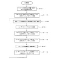
まず、TS140を絶対座標系上における位置が既知の場所に設置する(ステップS101)。また、この設置位置におけるTS140の姿勢(方位角)を特定しておく。これは、通常行われるTS(トータルステーション)の設置時における外部標定要素を特定する作業と同じである。絶対座標系とは、例えばGNSSで用いられる世界座標系であり、緯度、経度、平均海面からの高度で位置が特定される座標系である。位置の特定は、例えば、GNSSを用いた相対測位により行う。また、予め位置が特定されている点にTS140を設置する形態でもよい。座標系として、現場で設定されたローカル座標系を用いることもできる。 (Processing procedure)
First, theTS 140 is installed at a position whose position on the absolute coordinate system is known (step S101). Further, the attitude (azimuth angle) of the TS 140 at this installation position is specified. This is the same as the operation of specifying an external orientation element at the time of installation of a TS (total station) which is usually performed. The absolute coordinate system is, for example, a world coordinate system used in GNSS, and is a coordinate system whose position is specified by latitude, longitude, and altitude from the average sea level. The specification of the position is performed, for example, by relative positioning using GNSS. Further, the TS 140 may be installed at a point whose position is specified in advance. As a coordinate system, it is also possible to use a local coordinate system set in the field.
まず、TS140を絶対座標系上における位置が既知の場所に設置する(ステップS101)。また、この設置位置におけるTS140の姿勢(方位角)を特定しておく。これは、通常行われるTS(トータルステーション)の設置時における外部標定要素を特定する作業と同じである。絶対座標系とは、例えばGNSSで用いられる世界座標系であり、緯度、経度、平均海面からの高度で位置が特定される座標系である。位置の特定は、例えば、GNSSを用いた相対測位により行う。また、予め位置が特定されている点にTS140を設置する形態でもよい。座標系として、現場で設定されたローカル座標系を用いることもできる。 (Processing procedure)
First, the
次に、路面100上において、台車110上のレーザースキャナ130の全周反射プリズム131をTS140により捕捉する(ステップS102)。これは、手動による視準、TS140が備えるターゲット探索機能による自動視準、あるいは手動による大凡の視準と自動視準の組み合わせによって行われる。
Next, on the road surface 100, the full circumference reflecting prism 131 of the laser scanner 130 on the carriage 110 is captured by the TS 140 (step S102). This is performed by manual collimation, automatic collimation by the target search function of the TS 140, or a combination of approximate collimation and automatic collimation by manual operation.
次に、台車を人手で押し、第1の停止位置に向かって移動させる。この際、TS140による全周反射プリズム131の捕捉および測位を継続して行う。台車110にはTS140のコントローラとなる端末111が固定されている(台車110を押す人が手にしていてもよい)。この端末111には、目標となる停止位置の方向と距離が表示され、台車110の誘導が行われる(ステップS103)。この表示は、TS140による全周プリズム131の測位データ、予め設定されている停止位置の位置データに基づき作成される。
Next, the dolly is manually pushed and moved toward the first stop position. At this time, capturing and positioning of the all-round reflecting prism 131 by the TS 140 are continuously performed. A terminal 111 serving as a controller of the TS 140 is fixed to the carriage 110 (a person pushing the carriage 110 may be in hand). The direction and distance of the target stop position are displayed on this terminal 111, and guidance of the carriage 110 is performed (step S103). This display is created based on the positioning data of the whole circumference prism 131 by the TS 140 and the position data of the stop position set in advance.
台車110を押す作業者は、端末111に表示される表示を見ながら、台車110を停止位置まで押して行く。台車が停止位置に到達した段階で、端末111の表示における停止位置までの距離が0となり、またその旨を報知する報知表示がされ、更に報知音が端末111から発せられる。この報知処理を受けて、作業者は台車110を予め設定された停止位置に停止させる。
The operator pushing the carriage 110 pushes the carriage 110 to the stop position while watching the display displayed on the terminal 111. When the carriage reaches the stop position, the distance to the stop position in the display of the terminal 111 becomes 0, and a notification display notifying that effect is displayed, and a notification sound is emitted from the terminal 111. In response to the notification process, the worker stops the carriage 110 at a preset stop position.
次に、自動整準台120の自動正準機能を用いてレーザースキャナ130の垂直軸が鉛直方向に一致するように、その傾きの補正が行われる(ステップS104)。自動整準台120としては、各種の傾斜センサ(例えば、気泡を光学的に検出する方式等)により傾きを検出し、それに基づき傾きをアクチュエータ等で調整する形式のものが利用される。整準台に関する技術としては、例えば、特開2009-14368号公報に記載されている。整準を自動でなく、マニュアル操作あるいは半自動で行う形態も可能である。
Next, the inclination of the laser scanner 130 is corrected so that the vertical axis of the laser scanner 130 coincides with the vertical direction using the automatic standardizing function of the automatic leveling table 120 (step S104). As the automatic leveling table 120, a type in which the inclination is detected by various inclination sensors (for example, a method of optically detecting a bubble or the like) and the inclination is adjusted by an actuator or the like based thereon is used. The technology related to the leveling table is described, for example, in Japanese Patent Laid-Open No. 2009-14368. A mode is also possible in which leveling is performed not manually but manually or semi-automatically.
次に、TS140によるレーザースキャナ130に固定された全周反射プリズム131の測位を行う(ステップS105)。この処理により、レーザースキャナ130の整準処理後におけるレーザースキャナ130の精密な位置の特定が行われる。全周反射プリズム131の測位データは、端末111に送られる。なお、レーザースキャナ130と全周反射プリズム131との間のオフセット値(位置のずれ)は既知であるので、全周反射プリズム131の測位を行うことで、レーザースキャナ130の測位が行われる。これは、全周反射プリズム141とTS140においても同じである。
Next, positioning of the all-round reflection prism 131 fixed to the laser scanner 130 by the TS 140 is performed (step S105). By this process, the precise position of the laser scanner 130 after the leveling process of the laser scanner 130 is specified. The positioning data of the all-round reflection prism 131 is sent to the terminal 111. In addition, since the offset value (displacement) between the laser scanner 130 and the all-round reflection prism 131 is known, the positioning of the laser scanner 130 is performed by measuring the all-round reflection prism 131. The same applies to the all-round reflection prism 141 and the TS 140.
次に、位置が正確に特定されたレーザースキャナ130を用いて全周反射プリズム141(TS140)の測位を行う(ステップS106)。全周反射プリズム141の測位データは端末111に送られる。
Next, positioning of the all-round reflection prism 141 (TS 140) is performed using the laser scanner 130 whose position is accurately specified (step S106). The positioning data of the all-round reflection prism 141 is sent to the terminal 111.
次に、絶対座標系上で特定されたレーザースキャナ130の位置とTS140の位置とに基づき、レーザースキャナ130の外部標定要素が算出される(ステップS107)。ここで、レーザースキャナ130の外部標定要素における位置はTS140により測位され、その測位データは端末111で受け付けられている。よって、ここではレーザースキャナ130の姿勢の算出が行われる。この処理は、端末111の外部標定要素算出部66で行なわれる。
Next, an external orientation element of the laser scanner 130 is calculated based on the position of the laser scanner 130 specified on the absolute coordinate system and the position of the TS 140 (step S107). Here, the position in the external orientation element of the laser scanner 130 is positioned by the TS 140, and the positioning data is received by the terminal 111. Therefore, the attitude of the laser scanner 130 is calculated here. This process is performed by the external orientation element calculator 66 of the terminal 111.
レーザースキャナ130の外部標定要素を求めたら、レーザースキャナ130を用いた路面100のレーザースキャンを行う(ステップS108)。この際、ステップS107においてレーザースキャナ140の外部標定要素が算出されているので、路面100のレーザースキャンデータを絶対座標系上で得ることができる。
After the external determination element of the laser scanner 130 is obtained, laser scanning of the road surface 100 using the laser scanner 130 is performed (step S108). Under the present circumstances, since the external positioning element of the laser scanner 140 is calculated in step S107, the laser scan data of the road surface 100 can be obtained on an absolute coordinate system.
ステップS103で誘導された停止位置での路面100のレーザースキャンが終了したら、ステップS103の前段階に戻り、次の停止位置へのTS140による誘導による移動が行われ、ステップ104以下の処理が繰り返される。こうして、予め設定された複数の停止位置への移動、そこで停止してのレーザースキャンのサイクルを繰り返し、路面のレーザースキャンデータを取得する。
When the laser scanning of the road surface 100 at the stop position guided in step S103 is completed, the process returns to the previous step of step S103, movement by guidance by the TS 140 to the next stop position is performed, and the processing from step 104 onward is repeated. . In this way, the movement to a plurality of preset stop positions and the cycle of the laser scanning after stopping there are repeated to acquire the laser scanning data of the road surface.
上記の処理では、TS140により予め定めた停止位置への台車110の誘導および停止位置におけるレーザースキャナ130の位置決めが行われる。また、レーザースキャナ130による全周反射プリズム141の測位により、停止位置でのレーザースキャナ130の外部標定要素の算出が行われる。この際、台車110を押して移動させる以外の人手は必要なく、高い作業効率が得られる。
In the above process, the TS 140 guides the carriage 110 to a predetermined stop position and positions the laser scanner 130 at the stop position. Further, the external positioning element of the laser scanner 130 at the stop position is calculated by the positioning of the all-round reflection prism 141 by the laser scanner 130. At this time, there is no need for a person other than pushing and moving the carriage 110, and high work efficiency can be obtained.
(変形例)
必要なレーザースキャン点群の密度が得られるように、隣接するレーザースキャナの停止位置からのレーザースキャン範囲を重複させる制御も可能である。本発明では、TSによりレーザースキャナの位置を精密に把握しているので、このような作業も容易である。 (Modification)
It is also possible to control to overlap the laser scan range from the stop position of the adjacent laser scanner so as to obtain the required density of the laser scan point group. In the present invention, since the position of the laser scanner is precisely grasped by the TS, such an operation is easy.
予め定めた複数の停止予定位置の一部における位置の特定に、TSを用いる形態も可能である。この場合、TSを用いない停止位置の特定は、shape matchingで行う。shape matchingは、異なる2点から行われた重複する領域に対するレーザースキャンにより、レーザースキャナの移動経路および外部標定要素の変化を追跡する技術である。
It is also possible to use a TS to specify the position of a part of a plurality of predetermined planned stop positions. In this case, specification of the stop position without using TS is performed by shape matching. Shape matching is a technology for tracking changes in the movement path and external orientation factor of a laser scanner by laser scanning on overlapping regions performed from two different points.
例えば、台車110の停止予定位置が複数ある場合に、最初と最後の停止予定位置の特定にTS140を用い、その他の停止予定位置の特定は、上記のshape matchingを用いる例が挙げられる。
For example, when there are a plurality of planned stop positions of the carriage 110, the TS 140 may be used to specify the first and last planned stop positions, and the other planned stop positions may be specified using shape matching described above.
また、レーザースキャナ130とTS140が互いに見通せ、相互の測位が可能な状態において、図1の原理を用いた台車110の停止位置の特定を行い、そうでない状態で上記のshape matchingを用いたレーザースキャナ130の位置特定処理により停止予定位置の特定を行う。
In addition, when the laser scanner 130 and the TS 140 can see each other and the mutual positioning can be performed, the stop position of the carriage 110 is specified using the principle of FIG. 1 and the laser scanner using the above shape matching is used otherwise. The planned stop position is specified by the position specifying process 130.
(むすび)
以上述べた技術では、台車110に搭載され、全周反射プリズム131を備えたレーザースキャナ130による測位データと、地上に固定され、全周反射プリズム141を備えたトータルステーション140による測位データとに基づきレーザースキャナ130の外部標定要素の算出を行う外部標定要素算出部66と、トータルステーション140による全周反射プリズム131の測位データに基づき、予め定められた停止位置へ台車110を誘導するための誘導処理を行う報知処理部(誘導処理部)67とを備えた端末111であって、レーザースキャナ130の外部標定要素の算出において、レーザースキャナ130による測位データは、全周反射プリズム141の測位データであり、トータルステーション140による測位データは、全周反射プリズム131の測位データである内容が開示されている。 (End)
In the technology described above, the laser is based on the positioning data by thelaser scanner 130 mounted on the carriage 110 and provided with the all-round reflection prism 131 and the positioning data by the total station 140 fixed on the ground and provided with the all-round reflection prism 141 Based on the external orientation element calculator 66 for calculating the external orientation element of the scanner 130 and the positioning data of the all-round reflecting prism 131 by the total station 140, the guidance processing for guiding the carriage 110 to a predetermined stop position is performed. In the terminal 111 including the notification processing unit (guidance processing unit) 67, in the calculation of the external positioning element of the laser scanner 130, the positioning data by the laser scanner 130 is the positioning data of the all-round reflecting prism 141, and the total station The positioning data by 140 is Content is a positioning data peripheral reflecting prism 131 is disclosed.
以上述べた技術では、台車110に搭載され、全周反射プリズム131を備えたレーザースキャナ130による測位データと、地上に固定され、全周反射プリズム141を備えたトータルステーション140による測位データとに基づきレーザースキャナ130の外部標定要素の算出を行う外部標定要素算出部66と、トータルステーション140による全周反射プリズム131の測位データに基づき、予め定められた停止位置へ台車110を誘導するための誘導処理を行う報知処理部(誘導処理部)67とを備えた端末111であって、レーザースキャナ130の外部標定要素の算出において、レーザースキャナ130による測位データは、全周反射プリズム141の測位データであり、トータルステーション140による測位データは、全周反射プリズム131の測位データである内容が開示されている。 (End)
In the technology described above, the laser is based on the positioning data by the
2.第2の実施形態
トンネルの内壁(側壁および天井)をレーザースキャンする場合の例を図6に示す。この場合、TS140はトンネル内に設置され、台車110に載せられたレーザースキャナ130によるトンネル内壁のレーザースキャンが行なわれる。この場合、トンネルの内部において、図5の処理が実行される。もちろん、トンネルの壁面に加えて路面のレーザースキャンも可能である。 2. Second Embodiment An example of laser scanning of the inner wall (side wall and ceiling) of a tunnel is shown in FIG. In this case, theTS 140 is installed in the tunnel, and laser scanning of the inner wall of the tunnel is performed by the laser scanner 130 mounted on the carriage 110. In this case, the process of FIG. 5 is performed inside the tunnel. Of course, in addition to the wall of the tunnel, laser scanning of the road surface is also possible.
トンネルの内壁(側壁および天井)をレーザースキャンする場合の例を図6に示す。この場合、TS140はトンネル内に設置され、台車110に載せられたレーザースキャナ130によるトンネル内壁のレーザースキャンが行なわれる。この場合、トンネルの内部において、図5の処理が実行される。もちろん、トンネルの壁面に加えて路面のレーザースキャンも可能である。 2. Second Embodiment An example of laser scanning of the inner wall (side wall and ceiling) of a tunnel is shown in FIG. In this case, the
本発明は、移動と停止を交互に行ない、停止時にレーザースキャンを行う技術に利用できる。
The present invention can be used as a technique for alternately moving and stopping and performing laser scanning at the time of stopping.
100…路面、110…台車、120…整準台、130…レーザースキャナ、131…全周反射プリズム、132…本体部、133…光学部、134…基台部、140…TS(トータルステーション)、141…全周反射プリズム、142…水平回転部、143…三脚、144…基台部、145…鉛直回転部。
DESCRIPTION OFSYMBOLS 100 ... Road surface, 110 ... Dolly, 120 ... Leveling stand, 130 ... Laser scanner, 131 ... All around reflective prism, 132 ... Body part, 133 ... Optical part, 134 ... Base part, 140 ... TS (Total station), 141 ... whole circumference reflection prism, 142 ... horizontal rotation part, 143 ... tripod, 144 ... base part, 145 ... vertical rotation part.
DESCRIPTION OF
Claims (5)
- 移動体に搭載され、第1の反射プリズムを備えたレーザースキャナによる測位データと、地上に固定され、第2の反射プリズムを備えたトータルステーションによる測位データとに基づき前記レーザースキャナの外部標定要素の算出を行う外部標定要素算出部と、
前記トータルステーションによる前記第1の反射プリズムの測位データに基づき、予め定められた停止位置に前記移動体を誘導するための誘導処理を行う誘導処理部と
を備えた測量装置であって、
前記レーザースキャナの前記外部標定要素の算出において、
前記レーザースキャナによる前記測位データは、前記第2の反射プリズムの測位データであり、
前記トータルステーションによる前記測位データは、前記第1の反射プリズムの測位データである測量装置。 Calculation of external orientation factor of the laser scanner based on positioning data by a laser scanner mounted on a mobile body and equipped with a first reflecting prism and positioning data fixed on the ground by a total station equipped with a second reflecting prism An external orientation element calculation unit that
And a guidance processing unit that performs guidance processing for guiding the moving object to a predetermined stop position based on the positioning data of the first reflecting prism by the total station.
In the calculation of the external orientation element of the laser scanner,
The positioning data by the laser scanner is positioning data of the second reflecting prism,
The surveying device, wherein the positioning data by the total station is positioning data of the first reflecting prism. - 請求項1に記載の測量装置と、
前記レーザースキャナの整準を行うための整準装置と
を備える測量システム。 The surveying instrument according to claim 1;
And a leveling device for leveling the laser scanner. - 前記整準装置による前記レーザースキャナの整準動作の後、前記トータルステーションによる前記第1の反射プリズムの測位が行われる請求項2に記載の測量システム。 The surveying system according to claim 2, wherein after the leveling operation of the laser scanner by the leveling device, positioning of the first reflecting prism by the total station is performed.
- 移動体に搭載され、第1の反射プリズムを備えたレーザースキャナによる測位データと、地上に固定され、第2の反射プリズムを備えたトータルステーションによる測位データとに基づく前記レーザースキャナの外部標定要素の算出と、
前記トータルステーションによる前記第1の反射プリズムの測位データに基づき、予め定められた停止位置に前記移動体を誘導する誘導処理と
を行う測量方法であり、
前記レーザースキャナの前記外部標定要素の算出は、前記トータルステーションによる前記第1の反射プリズムの測位データと、前記レーザースキャナによる前記第2の反射プリズムの測位データとに基づき行われる測量方法。 Calculation of the external orientation element of the laser scanner based on positioning data by a laser scanner mounted on a mobile body and equipped with a first reflecting prism and positioning data fixed on the ground by a total station equipped with a second reflecting prism When,
A surveying method for performing guidance processing for guiding the mobile unit to a predetermined stop position based on the positioning data of the first reflecting prism by the total station.
The surveying method wherein calculation of the external orientation element of the laser scanner is performed based on positioning data of the first reflecting prism by the total station and positioning data of the second reflecting prism by the laser scanner. - コンピュータに読み取らせて実行させるプログラムであって、
コンピュータに
移動体に搭載され、第1の反射プリズムを備えたレーザースキャナによる測位データと、地上に固定され、第2の反射プリズムを備えたトータルステーションによる測位データとに基づく前記レーザースキャナの外部標定要素の算出と、
前記トータルステーションによる前記第1の反射プリズムの測位データに基づき、予め定められた停止位置に前記移動体を誘導する誘導処理と
を実行させ、
前記レーザースキャナの前記外部標定要素の算出は、前記トータルステーションによる前記第1の反射プリズムの測位データと、前記レーザースキャナによる前記第2の反射プリズムの測位データとに基づき行われる測量用プログラム。
A program that causes a computer to read and execute
The external positioning element of the laser scanner based on positioning data by a laser scanner mounted on a mobile body on a computer and equipped with a first reflecting prism and positioning data on a total station fixed on the ground and equipped with a second reflecting prism Calculation of,
Performing a guiding process of guiding the moving body to a predetermined stop position based on the positioning data of the first reflecting prism by the total station;
Calculation of the said external orientation element of the said laser scanner is the program for surveys performed based on the positioning data of the said 1st reflective prism by the said total station, and the positioning data of the said 2nd reflective prism by the said laser scanner.
Priority Applications (1)
| Application Number | Priority Date | Filing Date | Title |
|---|---|---|---|
| JP2019555405A JP7257326B2 (en) | 2017-11-27 | 2018-11-27 | Surveying instrument, surveying system, surveying method and surveying program |
Applications Claiming Priority (2)
| Application Number | Priority Date | Filing Date | Title |
|---|---|---|---|
| JP2017-226628 | 2017-11-27 | ||
| JP2017226628 | 2017-11-27 |
Publications (1)
| Publication Number | Publication Date |
|---|---|
| WO2019103154A1 true WO2019103154A1 (en) | 2019-05-31 |
Family
ID=66631571
Family Applications (1)
| Application Number | Title | Priority Date | Filing Date |
|---|---|---|---|
| PCT/JP2018/043566 WO2019103154A1 (en) | 2017-11-27 | 2018-11-27 | Surveying device, surveying system, surveying method, and surveying program |
Country Status (2)
| Country | Link |
|---|---|
| JP (1) | JP7257326B2 (en) |
| WO (1) | WO2019103154A1 (en) |
Cited By (7)
| Publication number | Priority date | Publication date | Assignee | Title |
|---|---|---|---|---|
| CN110318340A (en) * | 2019-06-21 | 2019-10-11 | 中交第二航务工程局有限公司 | A kind of cantilever construction hanging basket formwork fast-positioning device and localization method |
| CN110425982A (en) * | 2019-07-25 | 2019-11-08 | 中国十七冶集团有限公司 | Long-span space horizontal displacement monitoring method for early warning |
| CN111578918A (en) * | 2020-06-24 | 2020-08-25 | 平湖市中地测绘规划有限公司 | Total station control method and system applying same |
| CN115112106A (en) * | 2022-06-13 | 2022-09-27 | 北京兴宸伟业科技有限公司 | Method and system based on high-speed railway track geometric state measurement |
| JP7201863B1 (en) | 2022-06-28 | 2023-01-10 | クモノスコーポレーション株式会社 | Measuring device and measuring method |
| CN116005503A (en) * | 2023-01-10 | 2023-04-25 | 中铁四局集团第五工程有限公司 | Method, system, computer and readable storage medium for detecting position deviation of rail bearing table |
| JP7357115B2 (en) | 2018-03-01 | 2023-10-05 | 株式会社エムアールサポート | Surveying system, surveying method and installation equipment for the surveying system |
Citations (5)
| Publication number | Priority date | Publication date | Assignee | Title |
|---|---|---|---|---|
| JP2003527514A (en) * | 2000-03-17 | 2003-09-16 | サンドビク タムロック オサケ ユキチュア | Positioning method for unmanned mining vehicles |
| JP2014173990A (en) * | 2013-03-08 | 2014-09-22 | Topcon Corp | Measuring device |
| JP5748566B2 (en) * | 2011-05-31 | 2015-07-15 | 東急建設株式会社 | Three-dimensional shape information acquisition device |
| JP2016200521A (en) * | 2015-04-13 | 2016-12-01 | 前田建設工業株式会社 | Shape measurement method of unsupported excavated surface for tunnel |
| JP2017020972A (en) * | 2015-07-14 | 2017-01-26 | 東急建設株式会社 | Three-dimensional shape measurement device, three-dimensional shape measurement method, and program |
-
2018
- 2018-11-27 WO PCT/JP2018/043566 patent/WO2019103154A1/en active Application Filing
- 2018-11-27 JP JP2019555405A patent/JP7257326B2/en active Active
Patent Citations (5)
| Publication number | Priority date | Publication date | Assignee | Title |
|---|---|---|---|---|
| JP2003527514A (en) * | 2000-03-17 | 2003-09-16 | サンドビク タムロック オサケ ユキチュア | Positioning method for unmanned mining vehicles |
| JP5748566B2 (en) * | 2011-05-31 | 2015-07-15 | 東急建設株式会社 | Three-dimensional shape information acquisition device |
| JP2014173990A (en) * | 2013-03-08 | 2014-09-22 | Topcon Corp | Measuring device |
| JP2016200521A (en) * | 2015-04-13 | 2016-12-01 | 前田建設工業株式会社 | Shape measurement method of unsupported excavated surface for tunnel |
| JP2017020972A (en) * | 2015-07-14 | 2017-01-26 | 東急建設株式会社 | Three-dimensional shape measurement device, three-dimensional shape measurement method, and program |
Cited By (9)
| Publication number | Priority date | Publication date | Assignee | Title |
|---|---|---|---|---|
| JP7357115B2 (en) | 2018-03-01 | 2023-10-05 | 株式会社エムアールサポート | Surveying system, surveying method and installation equipment for the surveying system |
| CN110318340A (en) * | 2019-06-21 | 2019-10-11 | 中交第二航务工程局有限公司 | A kind of cantilever construction hanging basket formwork fast-positioning device and localization method |
| CN110425982A (en) * | 2019-07-25 | 2019-11-08 | 中国十七冶集团有限公司 | Long-span space horizontal displacement monitoring method for early warning |
| CN111578918A (en) * | 2020-06-24 | 2020-08-25 | 平湖市中地测绘规划有限公司 | Total station control method and system applying same |
| CN115112106A (en) * | 2022-06-13 | 2022-09-27 | 北京兴宸伟业科技有限公司 | Method and system based on high-speed railway track geometric state measurement |
| JP7201863B1 (en) | 2022-06-28 | 2023-01-10 | クモノスコーポレーション株式会社 | Measuring device and measuring method |
| JP2024004339A (en) * | 2022-06-28 | 2024-01-16 | クモノスコーポレーション株式会社 | Measurement device and measurement method |
| CN116005503A (en) * | 2023-01-10 | 2023-04-25 | 中铁四局集团第五工程有限公司 | Method, system, computer and readable storage medium for detecting position deviation of rail bearing table |
| CN116005503B (en) * | 2023-01-10 | 2023-09-22 | 中铁四局集团第五工程有限公司 | Method, system, computer and readable storage medium for detecting position deviation of rail bearing table |
Also Published As
| Publication number | Publication date |
|---|---|
| JP7257326B2 (en) | 2023-04-13 |
| JPWO2019103154A1 (en) | 2020-11-19 |
Similar Documents
| Publication | Publication Date | Title |
|---|---|---|
| WO2019103154A1 (en) | Surveying device, surveying system, surveying method, and surveying program | |
| US11822351B2 (en) | Three-dimensional information processing unit, apparatus having three-dimensional information processing unit, unmanned aerial vehicle, informing device, method and program for controlling mobile body using three-dimensional information processing unit | |
| EP2869024B1 (en) | Three-dimensional measuring method and surveying system | |
| CA2539903C (en) | Method and system for determining the spatial position of a hand-held measuring appliance | |
| EP3677872B1 (en) | Surveying instrument | |
| US9453729B2 (en) | Layout equipment and layout method | |
| US7701566B2 (en) | Surveying system | |
| US7081606B2 (en) | Position measuring system | |
| US20150160000A1 (en) | Automated layout and point transfer system | |
| JP6130078B2 (en) | Surveying information marking device, surveying information marking method | |
| JP2005214854A (en) | Survey system | |
| JP7313955B2 (en) | Surveying instrument, surveying method and surveying program | |
| JP2009229222A (en) | Measurement system | |
| JP2019128196A (en) | Surveying apparatus and surveying method | |
| US20130162971A1 (en) | Optical system | |
| KR20120064348A (en) | The apparatus and method of topography measuring | |
| US20130021618A1 (en) | Apparatus and method to indicate a specified position using two or more intersecting lasers lines | |
| JP7289252B2 (en) | Scanner system and scanning method | |
| JP6101032B2 (en) | Setting support apparatus, setting support method, and program | |
| RU2792054C1 (en) | Method for measurement of drive path of heading machine | |
| WO2024071287A1 (en) | Twist ring polygon mirror, light transmitter, and surveying system | |
| EP4239372A1 (en) | System and method of combining three dimensional data | |
| JP2023100945A (en) | Measurement device, measurement method, and measurement program | |
| JP2024050349A (en) | Light transmitters and surveying systems | |
| JP2019113491A (en) | Target device, measuring method, measuring device, and program for measurement |
Legal Events
| Date | Code | Title | Description |
|---|---|---|---|
| 121 | Ep: the epo has been informed by wipo that ep was designated in this application |
Ref document number: 18881373 Country of ref document: EP Kind code of ref document: A1 |
|
| ENP | Entry into the national phase |
Ref document number: 2019555405 Country of ref document: JP Kind code of ref document: A |
|
| NENP | Non-entry into the national phase |
Ref country code: DE |
|
| 122 | Ep: pct application non-entry in european phase |
Ref document number: 18881373 Country of ref document: EP Kind code of ref document: A1 |