WO2019102804A1 - 車両の重量測定装置 - Google Patents
車両の重量測定装置 Download PDFInfo
- Publication number
- WO2019102804A1 WO2019102804A1 PCT/JP2018/040412 JP2018040412W WO2019102804A1 WO 2019102804 A1 WO2019102804 A1 WO 2019102804A1 JP 2018040412 W JP2018040412 W JP 2018040412W WO 2019102804 A1 WO2019102804 A1 WO 2019102804A1
- Authority
- WO
- WIPO (PCT)
- Prior art keywords
- piston
- stopper ring
- bottom plate
- movable body
- measuring device
- Prior art date
- Legal status (The legal status is an assumption and is not a legal conclusion. Google has not performed a legal analysis and makes no representation as to the accuracy of the status listed.)
- Ceased
Links
Images














Classifications
-
- F—MECHANICAL ENGINEERING; LIGHTING; HEATING; WEAPONS; BLASTING
- F16—ENGINEERING ELEMENTS AND UNITS; GENERAL MEASURES FOR PRODUCING AND MAINTAINING EFFECTIVE FUNCTIONING OF MACHINES OR INSTALLATIONS; THERMAL INSULATION IN GENERAL
- F16F—SPRINGS; SHOCK-ABSORBERS; MEANS FOR DAMPING VIBRATION
- F16F9/00—Springs, vibration-dampers, shock-absorbers, or similarly-constructed movement-dampers using a fluid or the equivalent as damping medium
- F16F9/32—Details
- F16F9/54—Arrangements for attachment
-
- B—PERFORMING OPERATIONS; TRANSPORTING
- B60—VEHICLES IN GENERAL
- B60G—VEHICLE SUSPENSION ARRANGEMENTS
- B60G17/00—Resilient suspensions having means for adjusting the spring or vibration-damper characteristics, for regulating the distance between a supporting surface and a sprung part of vehicle or for locking suspension during use to meet varying vehicular or surface conditions, e.g. due to speed or load
- B60G17/015—Resilient suspensions having means for adjusting the spring or vibration-damper characteristics, for regulating the distance between a supporting surface and a sprung part of vehicle or for locking suspension during use to meet varying vehicular or surface conditions, e.g. due to speed or load the regulating means comprising electric or electronic elements
- B60G17/019—Resilient suspensions having means for adjusting the spring or vibration-damper characteristics, for regulating the distance between a supporting surface and a sprung part of vehicle or for locking suspension during use to meet varying vehicular or surface conditions, e.g. due to speed or load the regulating means comprising electric or electronic elements characterised by the type of sensor or the arrangement thereof
-
- B—PERFORMING OPERATIONS; TRANSPORTING
- B60—VEHICLES IN GENERAL
- B60G—VEHICLE SUSPENSION ARRANGEMENTS
- B60G11/00—Resilient suspensions characterised by arrangement, location or kind of springs
- B60G11/14—Resilient suspensions characterised by arrangement, location or kind of springs having helical, spiral or coil springs only
- B60G11/16—Resilient suspensions characterised by arrangement, location or kind of springs having helical, spiral or coil springs only characterised by means specially adapted for attaching the spring to axle or sprung part of the vehicle
-
- B—PERFORMING OPERATIONS; TRANSPORTING
- B60—VEHICLES IN GENERAL
- B60G—VEHICLE SUSPENSION ARRANGEMENTS
- B60G15/00—Resilient suspensions characterised by arrangement, location or type of combined spring and vibration damper, e.g. telescopic type
- B60G15/02—Resilient suspensions characterised by arrangement, location or type of combined spring and vibration damper, e.g. telescopic type having mechanical spring
- B60G15/06—Resilient suspensions characterised by arrangement, location or type of combined spring and vibration damper, e.g. telescopic type having mechanical spring and fluid damper
- B60G15/07—Resilient suspensions characterised by arrangement, location or type of combined spring and vibration damper, e.g. telescopic type having mechanical spring and fluid damper the damper being connected to the stub axle and the spring being arranged around the damper
-
- G—PHYSICS
- G01—MEASURING; TESTING
- G01G—WEIGHING
- G01G19/00—Weighing apparatus or methods adapted for special purposes not provided for in the preceding groups
- G01G19/08—Weighing apparatus or methods adapted for special purposes not provided for in the preceding groups for incorporation in vehicles
- G01G19/10—Weighing apparatus or methods adapted for special purposes not provided for in the preceding groups for incorporation in vehicles having fluid weight-sensitive devices
-
- G—PHYSICS
- G01—MEASURING; TESTING
- G01G—WEIGHING
- G01G19/00—Weighing apparatus or methods adapted for special purposes not provided for in the preceding groups
- G01G19/08—Weighing apparatus or methods adapted for special purposes not provided for in the preceding groups for incorporation in vehicles
- G01G19/12—Weighing apparatus or methods adapted for special purposes not provided for in the preceding groups for incorporation in vehicles having electrical weight-sensitive devices
-
- B—PERFORMING OPERATIONS; TRANSPORTING
- B60—VEHICLES IN GENERAL
- B60G—VEHICLE SUSPENSION ARRANGEMENTS
- B60G2200/00—Indexing codes relating to suspension types
- B60G2200/30—Rigid axle suspensions
- B60G2200/314—Rigid axle suspensions with longitudinally arranged arms articulated on the axle
-
- B—PERFORMING OPERATIONS; TRANSPORTING
- B60—VEHICLES IN GENERAL
- B60G—VEHICLE SUSPENSION ARRANGEMENTS
- B60G2204/00—Indexing codes related to suspensions per se or to auxiliary parts
- B60G2204/10—Mounting of suspension elements
- B60G2204/12—Mounting of springs or dampers
- B60G2204/124—Mounting of coil springs
- B60G2204/1244—Mounting of coil springs on a suspension arm
-
- B—PERFORMING OPERATIONS; TRANSPORTING
- B60—VEHICLES IN GENERAL
- B60G—VEHICLE SUSPENSION ARRANGEMENTS
- B60G2204/00—Indexing codes related to suspensions per se or to auxiliary parts
- B60G2204/40—Auxiliary suspension parts; Adjustment of suspensions
- B60G2204/418—Bearings, e.g. ball or roller bearings
-
- B—PERFORMING OPERATIONS; TRANSPORTING
- B60—VEHICLES IN GENERAL
- B60G—VEHICLE SUSPENSION ARRANGEMENTS
- B60G2204/00—Indexing codes related to suspensions per se or to auxiliary parts
- B60G2204/40—Auxiliary suspension parts; Adjustment of suspensions
- B60G2204/43—Fittings, brackets or knuckles
-
- B—PERFORMING OPERATIONS; TRANSPORTING
- B60—VEHICLES IN GENERAL
- B60G—VEHICLE SUSPENSION ARRANGEMENTS
- B60G2400/00—Indexing codes relating to detected, measured or calculated conditions or factors
- B60G2400/60—Load
Definitions
- the present invention relates to a device for measuring the weight of a vehicle, for example, a device for measuring the weight of a vehicle, which is incorporated in a suspension system of a vehicle and detects overload.
- Overloading may lower the motor performance of the vehicle or damage components, which may cause an accident. For example, there are a number of factors leading to an accident or the like, such as damage to an axle (hub), damage to a tire (burst), long braking distance and overheating of a brake to make it difficult to make it effective.
- Road maintenance costs are incurred because road damage becomes severe due to overloading.
- the load measurement (load weight measurement) of a vehicle was performed by placing the vehicle to be measured on a platform balance.
- the installation of the platform balance requires a large facility, a large installation space, and increases the installation cost. Therefore, the number of mounts that can be installed is limited, and it is physically impossible to measure many vehicles.
- Patent Document 1 many simple load measuring devices have been proposed that can be mounted on a vehicle itself to measure a load.
- Patent Document 1 is a simple load measuring device that measures a load by detecting a compressive strain.
- This load measuring device has a base assembly, a sensor element for detecting compressive strain, and a circuit board.
- the base assembly two welded portions are welded to different attachment points of a load-bearing member that expands and contracts when a vehicle load is applied.
- the compressive strain detection sensor element is supported by the base assembly, and the output changes when the base assembly expands and contracts in the direction in which the two welded parts move closer to or away from each other due to a change in load applied to the vehicle.
- the circuit board is mounted with an amplifier for amplifying the output of the sensor element for detecting compressive strain.
- Patent Document 2 the weight measurement device of Patent Document 2 is integrally provided in the suspension device.
- the piston is guided axially in sliding contact with the collar by the coil spring of the suspension system. Then, the pressure is applied to the measurement fluid filled in the oil chamber by pressing the diaphragm, and the pressure change is detected by the pressure sensor.
- the weight measuring device disclosed in Patent Document 2 is roughly divided into two functional blocks.
- the first functional block is provided with an oil pressure chamber (oil chamber) filled with a measurement fluid (hydraulic oil), a diaphragm configured to be able to press and deform a part of the oil chamber, and communication with the oil chamber. And a pressure sensor for detecting a change in pressure in the oil chamber due to the pressure of the load, and a load detection unit (attachment body) fixed to the vehicle.
- the second functional block is a piston (moving body) that moves in accordance with a load by the elastic force of a spring or the like to press the diaphragm.
- This type of weight measuring device is mainly targeted at small commercial vehicles.
- the front wheel is often a strut type or a double wishbone type
- the rear wheel is often a trailing arm type, a semi-trailing arm type, or a torsion beam type.
- the diaphragm and pressure sensor are attached to the bottom plate when incorporated in the rear wheel suspension system and attached to the top plate when incorporated in the front wheel suspension system.
- Patent Document 2 As described above, not only a simple, inexpensive, and durable vehicle weight measuring device is used, but also separation between the mounting body and the moving body is prevented, and the relative position between the mounting body and the moving body The purpose is to prevent rotation.
- a stopper ring partially provided with a notch is bolted to the outer peripheral portion of the piston constituting the moving body, and the notch of the bolted stopper ring is attached It is fitted to a projection provided on a part of the outer periphery of the bottom plate constituting the body.
- the weight measuring device having such a configuration is disposed in combination with the suspension system (suspension) of the vehicle, in particular, the coil spring and the shock absorber, its use in a severe environment exposed to mud water or dust is assumed. Be done.
- the oil chamber is provided on the bottom plate (attachment body), and since the bottom plate is attached to the arm, it is always placed close to the ground.
- a weight measurement device for a front wheel needs to apply a load from a spring or the like to a diaphragm of a mounting body (load detection unit). For that purpose, it is necessary to secure the movement of the piston that constitutes the movable body (piston portion), and a gap is provided between the collar that constitutes the mounting body and the piston that constitutes the movable body. .
- this type of weight measuring device is provided near the road surface, it is easily exposed to the environment in contact with water, dust, pebbles and the like.
- the mounting body (load detection unit) and the moving body (piston portion) since there is a gap between the mounting body (load detection unit) and the moving body (piston portion), from the clearance between the mounting body (load detection portion) and the moving body (piston portion) There is a problem that water, dust, pebbles, etc. easily penetrate and are difficult to discharge, and if water or the like accumulates, rust, corrosion, etc. will occur, the strength will decrease, and the function will be lost. There is a risk of
- the weight measuring device of a vehicle according to the present invention is used not only in the field of overload prevention described above as an example, but, for example, it performs shift control according to the load weight according to the load load.
- the field of improving fuel efficiency in the field of improving safety by making brake control considering weight distribution, or in the field of improving comfort by controlling control to keep the steering atmosphere constant.
- the above-mentioned problem is one of the important solutions since it is also available and used in various fields.
- the present invention has been made to solve the above-mentioned problems of the prior art, and the problem is that while the piston shape is simplified, both separation and relative rotation of the mounting body and the moving body are achieved.
- Providing a vehicle weight measuring device capable of preventing the Another object of the present invention is to prevent foreign matter from invading the movement allowable gap of the moving body which is inevitably formed between the mounting body and the moving body.
- Another object of the present invention is to provide a vehicle weight measuring device capable of preventing the entry of foreign matter such as water from between the mounting body and the moving body.
- a first aspect of the present invention relates to a moving body that moves by the elastic force of a spring; A pressure-deformable diaphragm by movement of the movable body, an oil chamber filled with a predetermined measurement fluid, an internal pressure changeable by the pressure of the diaphragm, and a pressure sensor capable of detecting a pressure change in the oil chamber
- a mounting body including at least A stopper ring provided between the moving body and the mounting body; And a rotation blocking portion that blocks relative rotation between the movable body and the mounting body, The stopper ring separates the movable body from the mounting body without impeding the movement of the movable body at a fixed portion fixed to any one of the movable body and the mounting body, and at the other.
- a separation stop unit to prevent the The said rotation prevention part was set as the weight measuring device of the vehicle characterized by including the pin fitted over the said moving body and the said attachment body.
- the mounting body is installed with the lower surface side in contact with the arm of the suspension system, is open at the upper surface side, and covers the opening area by the diaphragm.
- the vehicle is characterized in that the movable body is movable in the longitudinal direction of the suspension and includes a piston capable of pressing the diaphragm by the elastic force of a spring of the suspension. It is.
- the stopper ring has a cylindrical portion covering the outer periphery of the bottom plate and the piston, and a lower surface of the cylindrical portion smaller in diameter than the outer diameter of the bottom plate. And an annular portion having an inner diameter of A part of the cylindrical portion is press-fitted and fixed to the outer periphery of the piston to function as a fixing portion, The annular portion functions as a separation and dropout prevention portion that prevents separation and detachment of the movable body and the attachment body by being locked on the lower surface of the bottom plate without preventing movement of the movable body.
- the rotation preventing portion extends over a first fitting hole provided in the piston, a first notch groove provided in the bottom plate, the first fitting hole, and the first notch groove. It is a weight measuring device of a vehicle characterized by comprising a pin that can be fitted.
- the stopper ring has a cylindrical portion covering the outer periphery of the bottom plate and the piston, and a lower surface of the cylindrical portion smaller in diameter than the outer diameter of the bottom plate. And an annular portion having an inner diameter of A part of the cylindrical portion is press-fitted and fixed to the outer periphery of the piston to function as a fixing portion, The annular portion functions as a separation and dropout prevention portion that prevents separation and detachment of the movable body and the attachment body by being locked on the lower surface of the bottom plate without preventing movement of the movable body.
- the rotation preventing portion covers a second notch groove provided in the piston, a second fitting hole provided in the bottom plate, the second notch groove, and the second fitting hole. It is a weight measuring device of a vehicle characterized by comprising a pin that can be fitted.
- a moving body which moves by the elastic force of a spring;
- a pressure-deformable diaphragm by movement of the movable body, an oil chamber filled with a predetermined measurement fluid, an internal pressure changeable by the pressure of the diaphragm, and a pressure sensor capable of detecting a pressure change in the oil chamber
- a mounting body including at least A stopper ring provided between the moving body and the mounting body;
- a rotation blocking portion that blocks relative rotation between the movable body and the mounting body, The stopper ring separates the movable body from the mounting body without impeding the movement of the movable body at a fixed portion fixed to any one of the movable body and the mounting body, and at the other.
- a separation stop unit to prevent the In the vehicle weight measuring device the rotation preventing portion includes a pin fitted over any of the movable body, the attachment body, and the stopper body to which the fixing portion of the stopper ring is not fixed. It is.
- any one of the first to fifth aspects of the present invention foreign matter is prevented from entering the movement allowable gap formed between the facing surfaces of the movable body and the attachment body. And a sealing mechanism for the weight of the vehicle.
- a seventh aspect of the present invention is the vehicle weight measuring apparatus according to the sixth aspect, wherein the sealing mechanism comprises a seal portion provided between the stopper ring and the mounting body. It is said that.
- the seal portion is integrally provided with the stopper ring and in sliding contact with the mounting body. is there.
- the seal portion is integrally provided with the mounting body and is in sliding contact with the stopper ring. is there.
- an elastic plate is provided on the mounting surface side of the mounting body, The weight measuring device of a vehicle, wherein the sealing mechanism is provided on an outer peripheral edge of the elastic plate and has a seal portion slidingly contacting the stopper ring.
- a mobile unit which moves by the elastic force of a spring.
- a pressure-deformable diaphragm by movement of the movable body, an oil chamber filled with a predetermined measurement fluid, an internal pressure changeable by the pressure of the diaphragm, and a pressure sensor capable of detecting a pressure change in the oil chamber
- a mounting body including at least
- a weight measuring device of a vehicle including a sealing device between the moving body and the mounting body.
- a twelfth aspect of the invention is the weight of a vehicle according to the eleventh aspect, wherein a surface of the movable body facing the mounting body is provided with a tapered surface which is inclined downward from the position of the sealing device. It is to be a measuring device.
- the thirteenth invention is the twelfth invention. According to another aspect of the present invention, there is provided a weight measuring device for a vehicle, wherein the tapered surface is provided with a downward inclined concave groove.
- the mounting body is fixed to the vehicle side at the upper surface side and is open at the lower surface side, and the opening region is covered by the diaphragm.
- a top plate provided with a groove in which the oil chamber is formed; And a collar having a diameter larger than the opening area of the groove, and sandwiching and sealingly fixing a surface near the outer diameter of the diaphragm with a surface outside the opening area of the groove.
- the sealing device is a weight measuring device of a vehicle provided between the moving body and the collar.
- the present invention it is possible to provide a weight measuring device of a vehicle capable of preventing both separation and falling off and relative rotation of the mounting body and the moving body while simplifying the shape of the piston.
- a weight measuring device of a vehicle capable of preventing the entry of foreign matter such as water from between a mounting body and a moving body.
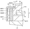
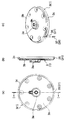
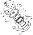
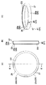
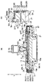
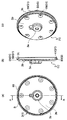
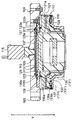
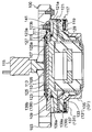
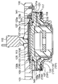
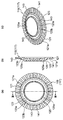
- FIG. 1 It is a schematic sectional drawing which shows 1st embodiment. It is a principal part enlarged view of 1st embodiment. It is a bottom plate (attachment body) which constitutes a first embodiment, and (a) is a top view, (b) is an II line sectional view of (a), (c) is a perspective view, and is a rotation The outline of the pin which comprises a blocking part is shown. It is a piston (moving body) which comprises 1st embodiment, Comprising: (a) is a top view, (b) is a II-II sectional view taken on the line of (a), (c) is a perspective view, rotation prevention The outline of the pin which comprises a part is shown. It is an exploded perspective view showing a first embodiment.
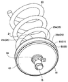
- FIG. 1 It is a perspective view which shows the state which combined the weight measurement apparatus of the vehicle in 4th embodiment, and the coil spring which is a suspension apparatus.
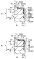
- FIG. 1 It is a schematic sectional drawing which shows 5th embodiment, Comprising: (a) is a general
- FIG. 1 It is a schematic sectional drawing which shows 6th embodiment, Comprising: (a) is a general
- (A) is a principal part expanded sectional view of 9th embodiment
- (b) is a principal part expanded sectional view of a 10th embodiment
- (c) is a principal part expanded sectional view of a 11th embodiment.
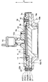
- the present embodiment is an embodiment in which the weight measuring device of a vehicle of the present invention is used for a suspension system (suspension) of a car, which is a suspension system for a rear wheel of a car, for example, as shown in FIG.
- a suspension system for a rear wheel of a car
- FIG. 14 An example of implementation applied to a suspension system (suspension) for rear wheels of an arm type automobile is assumed.
- the arrow in FIG. 14 indicates the rear of the vehicle.
- 1 to 5 show the first embodiment
- FIGS. 6 to 9 show the second embodiment
- FIGS. 10 to 13 show the third embodiment
- FIGS. 15 to 18 show the fourth embodiment
- FIGS. 19 to 20 show the fourth embodiment.
- FIG. 21 to 22 is the sixth embodiment
- FIG. 23 (a) is the seventh embodiment
- FIG. 23 (b) is the eighth embodiment
- FIG. 24 (a) is the ninth embodiment
- 24 (b) shows the tenth embodiment
- FIG. 24 (c) shows the eleventh embodiment.
- the present embodiment is an embodiment of the present invention, and is not to be construed as being limited to any of these, and design changes can be made within the scope of the present invention. According to the embodiment described below, it is possible to prevent foreign matter from invading the movement allowable gap of the moving body which is inevitably formed between the mounting body and the moving body.
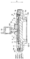
- the weight measuring device W of the vehicle includes a moving body (piston portion) 17 which moves by the elastic force of a spring (coil spring) 80, and a mounting body attached and fixed to the arm 90 side of a suspension device (suspension).
- (Load detection unit) 1 stopper ring 25 provided between movable body (piston portion) 17 and mounting body (load detection portion) 1, mobile body (piston portion) 17 and mounting body (load detection portion)
- a rotation blocker 31 for blocking relative rotation with respect to 1).
- the mounting body 1 is sandwiched between the bottom plate 3 installed with its lower surface side in contact with the arm 90 of the suspension system, the collar 9 provided on the top surface of the bottom plate 3, the bottom plate 3 and the collar 9
- An oil chamber 13 formed between the fixed diaphragm 7, the bottom plate 3 and the diaphragm 7 and filled with a predetermined measurement fluid (hydraulic oil), and provided on the lower surface of the bottom plate 3
- a pressure sensor 15 capable of detecting a change in pressure of the measurement fluid filled therein.
- the bottom plate 3 has a small diameter cylindrical portion 3a connecting the pressure sensor 15, a disc-shaped first surface portion 3b continuously and continuously formed in the horizontal direction from the upper surface of the small diameter cylindrical portion 3a, and And an annular second surface portion 3c which is step-like from the upper surface of the one surface portion 3b and which is integrally formed to have a diameter larger than that of the first surface portion 3b.
- a first notch groove 35 is formed on the outer periphery of the second surface portion 3c.
- the upper surface of the first surface portion 3b is provided with a groove 5 in which the oil chamber 13 is formed by being recessed toward the lower surface direction and the opening area is covered by the diaphragm 7.
- the collar 9 is formed to have a diameter larger than the opening area of the groove 5, and the surface near the outer diameter of the diaphragm 7 is sandwiched between the surface outside the opening 5 of the groove 5 It is done.
- symbol 11 in a figure shows a sealing member (O ring).
- reference numeral 61 in the figure indicates a soft, flat and annular elastic plate (for example, a rubber plate) disposed on the first surface portion 3 b of the bottom plate 3.
- the mounting body 1 of the present embodiment is characterized in that the bottom plate 3 is provided with the first cutout groove 35. Since other forms of the mounting body 1 may be known forms, it is also possible to adopt other forms of mounting bodies.
- the movable body 17 abuts on the diaphragm 7 and a piston 19 capable of pressing the diaphragm 7 in the vertical direction (direction indicated by arrow V in the figure) and abuts on the piston 19 and one end of a coil spring 80 of a suspension system not shown. And a spring seat 21 capable of receiving the (lower end) and pressing the piston 19 in the vertical direction V.
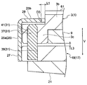
- the piston 19 is formed between the lower surface (collar facing surface) of the piston 19 and the upper surface (piston facing surface) of the collar 9 such that a movement allowance gap L3 in which the piston 19 can reciprocate in the vertical direction V is formed. Are arranged (see FIG. 2).
- the piston 19 includes a flange portion 19b which is integrally formed continuously and continuously in the horizontal direction from the outer periphery of the cylindrical portion 19a, and a first fitting hole 33 which is formed near the outer diameter of the flange portion 19b.
- the lower groove part 23 which can accommodate the pad 10 is concavely provided by the lower surface of the cylindrical part 19a.
- the lower surface of the cylindrical portion 19a abuts on the diaphragm 7 through the pad 10 which is fitted and stored in the lower groove portion 23.
- the outer diameter of the flange portion 19 b of the piston 19 is slightly larger than the outer diameter of the second surface portion 3 c of the bottom plate 3.
- the moving body 17 of the present embodiment is characterized in that the piston 19 is provided with the first fitting hole 33. Since the rest of the mobile unit 17 may be in a known form, it is also possible to adopt other forms of mobile unit.
- the stopper ring 25 is provided between the piston 19 and the bottom plate 3.
- a cylindrical portion 25a is formed in a cylindrical shape and is press-fitted and fixed to the outer periphery of the flange portion 19b of the piston 19, and continuously from the lower surface of the cylindrical portion 25a toward the axial center direction of the cylindrical portion 25a.
- an annular portion 25b having an inner diameter smaller than the outer diameter of the second surface 3c of the bottom plate 3 and capable of being engaged with the lower surface (stepped portion) of the second surface 3c of the bottom plate 3.
- the upper surface of the cylindrical part 25a is open
- the inner diameter D3 of the annular portion 25b is larger than the outer peripheral surface of the first surface 3b of the bottom plate 3.
- a predetermined gap L1 is formed between the inner diameter D3 of the annular portion 25b and the outer peripheral surface of the first surface portion 3b of the bottom plate 3.
- a part of the cylindrical portion 25 a fitted and fixed to the outer periphery of the flange portion 19 b of the piston 19 functions as the fixing portion 27.
- the annular portion 25 b functions as a separation and dropout prevention portion 29 that prevents separation and removal in the movement direction (the same direction as the vertical direction V) of the piston 19.
- the rotation prevention portion 31 adopts a configuration in which the pin 37 is fitted over the piston 19 and the bottom plate 3.
- the rotation prevention portion 31 includes a first fitting hole 33 provided in the flange portion 19 b of the piston 19, a first notch groove 35 provided in the second surface portion 3 c of the bottom plate 3, and a first fitting. It has a pin 37 which can be fitted over the hole 33 and the first notch groove 35.
- the first fitting hole 33 penetrates in a cylindrical shape from the upper surface to the lower surface near the outer periphery of the piston 19.
- the first notch groove 35 is a semicircular long groove in plan view from the upper surface to the lower surface in the second surface portion 3 c of the bottom plate 3.
- the first notch groove 35 is coaxial with the first fitting hole 33.
- the pin 37 is formed in a cylindrical shape having a length projecting from the first fitting hole 33, and is fitted and fixed to the first fitting hole 33.
- the pin 37 is formed in a square tube shape, and the first fitting hole 33 and the first notch groove 35 are also formed in the same square tube shape accordingly.
- the stopper ring 25 moves along with the piston 19 in the longitudinal direction (the same direction as the vertical direction V) of the suspension system by the cylindrical portion 25 a (fixing portion 27) fixed by press fitting to the outer periphery of the piston 19.
- the separation and detachment of the piston 19 and the bottom plate 3 are prevented by the annular part 25 b (separation detachment prevention part 29) that can be locked to the lower surface of the second surface 3 c. Therefore, even before being installed in a vehicle, the simple and inexpensive configuration eliminates the possibility of separating and dropping off the bottom plate 3 side (attachment body) and the piston 19 side (moving body). It is also useful for transportation to factories.
- the pin 37 is fixedly fitted in the first fitting hole 33 of the piston 19 in the first notch groove 35 of the bottom plate 3 to which the rotation preventing portion 31 of the present embodiment is fixed to the suspension device. Because of the fitting, relative rotation between the bottom plate 3 (mounting body) and the piston 19 (moving body) can be prevented easily and inexpensively. Therefore, there is no possibility that the bottom plate 3 (mounting body) and the piston 19 (moving body) relatively rotate in a state where the weight measuring device W is installed in the vehicle, and the diaphragm 7 and the piston 19 wear Does not occur. Therefore, it is only necessary to form the first fitting hole 33 penetrating the piston 19, and the piston shape can be simplified.
- the stopper ring 25 may be configured to be crimped to the piston 19 and can be designed and changed within the scope of the present invention.
- the material of the stopper ring 25 may be a cold-rolled steel plate. As a cold-rolled steel plate, SPCC material, SPCD material, SPCE material etc. can be illustrated. For example, as shown in FIG. 14, since the load measuring device is provided near the wheel of the automobile, when foreign matter such as muddy water intrudes into the inside of the load measuring device, the strength decreases or functions due to rust or corrosion. Losses may occur. In order to prevent these, it is preferable to form plating such as hot dip galvanization, electroplating, thin film organic composite plating, etc. on the surface of the cold rolled steel plate of the stopper ring 25.
- plating such as hot dip galvanization, electroplating, thin film organic composite plating, etc.
- the rotation preventing portion 31 extends over the second notch groove 39 provided in the piston 19, the second fitting hole 41 provided in the bottom plate 3, and the first notch groove 39 and the second fitting hole 41. And a pin 37 fitted. That is, in the present embodiment, the first notch groove 35 of the bottom plate 3 described in the first embodiment is replaced with a second fitting hole 41, and the first fitting hole 33 of the piston 19 is replaced with The second embodiment differs from the first embodiment in that the second notch groove 39 is used.
- the second notch groove 39 is a semicircular long groove provided on the upper surface to the lower surface and provided near the outer diameter of the flange portion 19 b of the piston 19.
- the second fitting hole 41 penetrates in a cylindrical shape from the upper surface to the lower surface at the second surface 3 c of the bottom plate 3.
- the second notch groove 39 and the second fitting hole 41 are provided coaxially.
- the configuration of the pin 37 is the same as that of the first embodiment. Since the effect of this embodiment is the same as that of the first embodiment, the description is omitted.
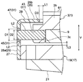
- the rotation preventing portion 31 includes a third fitting hole 43 which is horizontally cylindrically recessed from the outer periphery of the bottom plate 3 in the axial direction, and a through hole 45 provided in the cylindrical portion 25 a of the stopper ring 25. And a pin 47 fitted in the third fitting hole 43 and disposed in the insertion hole 45. That is, in the present embodiment, the bottom plate 3 and the piston 19 are connected by the pin 37 so as to prevent relative rotation between the bottom plate 3 and the piston 19 unlike the first embodiment and the second embodiment. By connecting the plate 3 and the stopper ring 25 with the pin 47, relative rotation between the bottom plate 3 and the piston 19 is prevented.
- the diameter of the insertion hole 45 is D1
- the outer diameter of the pin 47 is D2
- D1 and D2 have a relationship of D1> D2. That is, the stopper ring 25 must be movable in the vertical direction V together with the piston 19 to which the cylindrical portion 25a (the fixed portion 27) is press-fitted and fixed. Therefore, the insertion hole 45 is formed to have a diameter larger than that of the pin 47, and a movement gap (movement space) L2 is formed around the pin 47.
- the moving gap (moving space) L2 is at least as large as the movable distance of the piston 19 (moving body 17) in the vertical direction V.
- the insertion hole 45 may have a diameter larger than the pin 47 in the vertical direction V, and may have a diameter slightly larger than the pin 47 in the circumferential direction. That is, if the insertion hole 45 has a hole diameter that allows the pin 47 to be inserted and can move in the vertical direction V, the insertion hole 45 is formed in a long hole elongated in the vertical direction V It is also good.
- the pin 47 inserted and disposed in the insertion hole 45 provided in the cylindrical portion 25 a of the stopper ring 25 press-fitted and fixed to the outer periphery of the piston 19 is the third fitting hole of the bottom plate 3. It is a rotation prevention part structure configured to be fitted and fixed to 43. Therefore, relative rotation between the bottom plate 3 (mounting body) and the piston 19 (moving body) can be prevented easily and inexpensively. Therefore, there is no possibility that the bottom plate 3 (attachment body) and the piston 19 (moving body) relatively rotate in a state where the weight measuring device W is installed in the vehicle, and the bottom plate 3 (attachment body) There is also no wear with the piston 19 (moving body).
- the other operational effects are the same as those of the first embodiment, and therefore the description thereof is omitted.
- the sealing mechanism 51 prevents foreign matter from invading the movement allowable gap L3 formed between the mounting body (collar 9) and the moving body (piston 19).
- the sealing mechanism 51 is integrally provided on the stopper ring 25 in the weight measuring device W (see FIGS. 1 to 5) described in the first embodiment. Further, in the present embodiment, the outer diameter D4 of the spring seat 21 constituting the first embodiment is formed to be slightly larger than the outer diameter D5 of the flange portion 19b of the piston 19. In the present embodiment, the description of the sealing mechanism 51 which is the characteristic configuration is limited, and the description of the first embodiment is incorporated in other configurations and operational effects.
- the sealing mechanism 51 is a seal portion integrally molded with the stopper ring 25 by, for example, nitrile rubber.
- the sealing mechanism 51 is a base portion B integrally fixed so as to cover the lower surface of the annular portion 25b around the inner diameter D3 of the annular portion 25b (the separation falling-off preventing portion 29) from the inner surface of the cylindrical portion 25a of the stopper ring 25.
- a vertically extending first seal lip 53, 53 provided in an annular shape projecting obliquely from a region B1 fixed to the inner surface of the cylindrical portion 25a of the base portion B, and an annular portion of the base portion B
- a second seal lip 55 annularly provided so as to protrude in an inclined manner from the region B2 fixed to the lower surface of the second member 25b.
- the first seal lip 53, 53 is in sliding contact (pressure contact) with the outer surface of the second surface 3c of the bottom plate 3, and the inner surface of the cylindrical portion 25a of the stopper ring 25 and the outer surface of the second surface 3c of the bottom plate 3. Seal the gap L4 between them.
- the second seal lip 55 is in sliding contact (pressure contact) with the outer surface of the first surface 3 b of the bottom plate 3, and the outside diameter D 3 of the annular portion 25 b of the stopper ring 25 and the outside of the first surface 3 b of the bottom plate 3 Seal the gap L1 between the side surfaces.
- the lip tips of the first seal lips 53, 53 are in pressure contact with the outer surface of the second surface 3c of the bottom plate 3, and the lip tips of the second seal lip 55 are bottoms. It is designed to be in pressure contact with the outer surface of the first surface portion 3 b of the plate 3.
- the sealing mechanism (seal portion) 51 is optionally selected from materials generally used as a sealing material, such as polyacrylic rubber, silicone rubber, and fluoro rubber.
- sticker lip 53,53 is arbitrary.
- the first seal lip 53 may be used as a single one, or may be used in triple or more.
- the second seal lip 55 may be used in two or more series. Also, the lip tip of the first seal lip 53 and the lip tip of the second seal lip 55 may be bifurcatedly configured.
- the second seal lip 55 is provided, and the gap L1 between the inner diameter D3 of the annular portion 25b of the stopper ring 25 and the outer surface of the first surface portion 3b of the bottom plate 3 is sealed.
- the intrusion of foreign matter from the gap L1 into the weight measuring device W can be prevented. Therefore, the entry of foreign matter into the movement allowing gap L3 located inward of the gap L1 is prevented.
- the gap L4 between the inner surface of the cylindrical portion 25a of the stopper ring 25 and the outer surface of the second surface portion 3c of the bottom plate 3 is doubled in the vertical direction. Since the first seal lips 53, 53 for sealing in a (double) manner are provided, foreign matter intrusion into the movement allowing gap L3 is strongly prevented.
- the outer diameter D4 of the spring seat 21 is slightly larger than the outer diameter D5 of the flange portion 19b of the piston 19, and the upper end opening surface 25c of the stopper ring 25 is the lower surface of the spring seat 21.
- the upper end opening surface 25 c of the stopper ring 25 is configured in close contact with the lower surface of the spring seat 21, thereby preventing the entry of foreign matter.
- the seal is performed in the contact area between the spring seat 21 and the piston 19 and in the area where the cylindrical portion 25a of the stopper ring 25 functioning as the fixing portion 27 and the outer periphery of the flange 19b of the piston 19 are fitted and fixed.
- a member (O-ring) 57 is provided to improve sealing performance. Therefore, all foreign matter intrusion paths from above the weight measuring device W are also sealed, so that the foreign matter intrusion preventing effect on the movement allowable gap L3 is achieved in combination with the sealing mechanism (seal portion) 51 of the present embodiment. Further improve.
- the first seal lips 53 and 53 and the second seal lip 55 that constitute the sealing mechanism 51 are integrally formed with the stopper ring 25. Therefore, if the cylindrical portion 25a of the stopper ring 25 functioning as the fixing portion 27 is press-fitted and fixed to the outer surface of the flange portion 19b of the piston 19, the separation between the piston 19 and the bottom plate 3 is prevented and the required gap is simultaneously obtained. It can be sealed to prevent foreign matter from entering the movement allowable gap L3. Therefore, the procedure is simplified without the need to separately perform foreign object intrusion prevention processing to the movement allowable gap L3.
- sealing mechanism 51 of this embodiment is applicable also to the weight measurement apparatus W of 2nd embodiment or 3rd embodiment.
- the sealing mechanism (sheet portion) 51 is integrally provided on the bottom plate 3 in the weight measuring device W (see FIGS. 6 to 9) described in the second embodiment. Further, in the present embodiment, the outer diameter D4 of the spring seat 21 constituting the second embodiment is formed slightly larger than the outer diameter D5 of the flange portion 19b of the piston 19. In the present embodiment, the description is confined to the description of the sealing mechanism 51 which is a characteristic configuration, and the descriptions of the first embodiment, the second embodiment and the fourth embodiment are incorporated in other configurations and effects.
- the sealing mechanism (seal portion) 51 is inclined from the base portion B integrally fixed so as to cover the outer surface and the lower end surface of the second surface portion 3 c of the bottom plate 3 and the base portion region B 3 fixed to the outer surface. And a vertically extending third seal lip 59, 59 provided in an annular shape.
- the third seal lips 59, 59 are in sliding contact (pressure contact) with the inner surface of the cylindrical portion 25a of the stopper ring 25, and the inner surface of the cylindrical portion 25a of the stopper ring 25 and the outer surface of the second surface 3c of the bottom plate 3; Seal the gap L4 between them.
- the lip tips of the third seal lips 59, 59 are designed to be in pressure contact with the inner surface of the cylindrical portion 25 a of the stopper ring 25.
- sticker lip 59,59 is arbitrary.
- the third seal lip 59 may be used as a single one, or may be used in triple or more.
- the lip tip of the third seal lip 59 may be bifurcatedly configured.
- the gap L4 between the inner surface of the cylindrical portion 25a of the stopper ring 25 and the outer surface of the second surface portion 3c of the bottom plate 3 is sealed in duplicate in the vertical direction V Since the third seal lips 59, 59 are provided, foreign matter intrusion into the movement allowing gap L3 is strongly prevented. Therefore, foreign matter may prevent movement of the movable body in the vertical direction V and prevent accurate weight measurement, and mud water and the like may collect in the recess to cause rust and corrosion, resulting in strength reduction and functional loss. There can be no problems such as causing problems.
- the third seal lips 59, 59, 59 constituting the sealing mechanism 51 are integrally formed with the bottom plate 3. Therefore, if the cylindrical portion 25a of the stopper ring 25 is press-fitted and fixed to the outer surface of the flange portion 19b of the piston 19, separation and falling off of the piston 19 and the bottom plate 3 are prevented, and at the same time the gap L4 is sealed to allow movement allowance It is possible to prevent the entry of foreign matter into L3. Therefore, the procedure is simplified without the need to separately perform foreign object intrusion prevention processing to the movement allowable gap L3.
- the sealing mechanism 51 of the present embodiment can also be applied to the weight measuring device W shown in the first embodiment.
- the sealing mechanism (sheet portion) 51 is integrally provided on the elastic plate 61 in the weight measuring device W (see FIGS. 10 to 13) described in the third embodiment.
- the outer diameter D4 of the spring seat 21 constituting the third embodiment is formed slightly larger than the outer diameter D5 of the flange portion 19b of the piston 19, and the elastic plate 61 is formed. It has a tubular shape.
- the description will be limited to the description of the sealing mechanism 51 which is a characteristic configuration, and the descriptions of the first embodiment, the third embodiment and the fourth embodiment will be incorporated in other configurations and effects.
- the elastic plate 61 in the present embodiment has a cored bar 63, a soft covering portion 65, and a fourth seal lip 67.
- the cored bar 63 has an annular portion 63a and a cylindrical portion 63b integrally formed upward from the outer diameter of the annular portion 63a.
- the soft covering portion 65 covers the entire area of the cored bar 63.
- the elastic plate 61 is formed in a bottomed cylindrical shape including a lower surface 61 a and a cylindrical side surface 61 b by the core metal 63 and the covering portion 65. Further, the elastic plate 61 has a fourth seal lip 67 integrally protruding from the inner surface of the cylindrical side surface 61 b of the soft covering portion 65.
- the cored bar 63 is formed, for example, by subjecting a metal material used as a seal cored bar, such as cold rolled steel sheet such as SPCC or SPCD, to punching processing such as press processing and plastic processing.
- the lower surface 61 a is larger in diameter than the first surface 3 b of the bottom plate 3 and larger than the stopper ring 25.
- the lower surface 61a is disposed in contact (close contact) with the first surface 3b of the bottom plate 3 (see FIG. 21).
- the cylindrical side surface 61b is disposed to surround the outer surface of the cylindrical portion 25a of the stopper ring 25 (see FIG. 21).
- the sealing mechanism (seal portion) 51 protrudes from the covering portion area covering the inner peripheral surface of the cylindrical portion 63b in an inclined manner and is annularly provided in the fourth seal lip 67, 67, 67 of the triple in the vertical direction V It is configured.
- the fourth seal lip 67 is in sliding contact (pressure contact) with the outer surface of the cylindrical portion 25 a of the stopper ring 25 to seal between the outer surface of the cylindrical portion 25 a of the stopper ring 25.
- the distance between the triple fourth seal lips 67, 67, 67 is arbitrary.
- the fourth seal lip 67 may be used as a single one, or may be used in quadruple or more.
- the lip tip of the fourth seal lip 67 may be bifurcatedly configured.
- the fourth seal lip 67, 67, 67 that seals the outer surface of the cylindrical portion 25a of the stopper ring 25 in the vertical direction V in triple (triple) manner is provided.
- Foreign object intrusion is strongly blocked. Therefore, foreign matter may prevent movement of the movable body in the vertical direction V and prevent accurate weight measurement, and mud water and the like may collect in the recess to cause rust and corrosion, resulting in strength reduction and functional loss. There can be no problems such as causing problems.
- the sealing mechanism (seal portion) 51 of the present embodiment the sealing mechanism (seal portion) 51 of the first embodiment and the sealing mechanism (seal portion 51) of the second embodiment can be used in combination. Within the scope of the invention.
- the fourth seal lips 67, 67, 67 constituting the sealing mechanism 51 are integrally formed with the elastic plate 61. Therefore, if elastic plate 61 is disposed so as to cover the outer surface of cylindrical portion 25a of stopper ring 25, the required gap between the elastic plate 61 and the outer surface of cylindrical portion 25a of stopper ring 25 It can be sealed to prevent foreign matter from entering the movement allowable gap L3. Therefore, the procedure is simplified without the need to separately perform foreign object intrusion prevention processing to the movement allowable gap L3.
- sealing mechanism 51 of this embodiment is applicable also to the weight measurement apparatus W of 1st embodiment or 2nd embodiment. "Seventh embodiment"
- FIG. 23A shows the seventh embodiment, and in this embodiment, the stopper ring 25 and the weight measuring device W (see FIGS. 1 to 13) described in the first to third embodiments are described.
- Sealing mechanisms (sheet portions) 51 are integrally provided on both sides of the bottom plate 3. Further, in the present embodiment, the outer diameter D4 of the spring seat 21 constituting the first to third embodiments is formed to be slightly larger than the outer diameter D5 of the flange portion 19b of the piston 19 There is. In the present embodiment, the description will be limited to the description of the sealing mechanism 51 which is a characteristic configuration, and the descriptions of the first to fourth embodiments will be used for the other configurations and operational effects.
- the sealing mechanism (seal portion) 51 is the sealing mechanism 51 (the first seal lip 53 and the second seal lip 55) described in the fourth embodiment, and the sealing mechanism 51 (the fifth embodiment). And a third seal lip 59).
- the second seal lip 55 is in sliding contact (pressure contact) with the outer surface of the first surface 3 b of the bottom plate 3.
- the first seal lips 53, 53 are formed in duplicate in the vertical direction V, and come into sliding contact (pressure contact) with the outer surface of the second surface portion 3c of the bottom plate 3.
- the third seal lips 59, 59 are formed in two in the vertical direction V and are in sliding contact (pressure contact) with the inner surface of the cylindrical portion 25a of the stopper ring 25.
- the first seal lip 53 seals near the gap L1.
- the third seal lip 59 seals near the movement allowance gap L3. Therefore, the gap L4 between the inner surface of the cylindrical portion 25a of the stopper ring 25 and the outer surface of the second surface 3c of the bottom plate 3 is sealed in a quadruple manner.
- the lip tips of the first seal lips 53, 53 are pressed against the outer surface of the second surface 3c of the bottom plate 3, and the lip tips of the second seal lip 55 are The outer surface of the first surface 3b of the bottom plate 3 is in pressure contact, and the lip tips of the third seal lips 59, 59 are designed to be in pressure contact with the inner surface of the cylindrical portion 25a of the stopper ring 25.
- each of the 2nd 1st seal lip 53,53 and the 2nd 3rd seal lip 59,59 is arbitrary.
- the first seal lip 53 and the third seal lip 59 may be used as a single unit, or may be used in three or more series.
- the distance between the first seal lip 53 and the third seal lip 59 is optional.
- each lip tip of the first seal lip 53, the second seal lip 55, and the third seal lip 59 may be bifurcatedly configured.
- the second seal lip 55 seals the gap L1 between the inner diameter D3 of the annular portion 25b of the stopper ring 25 and the outer surface of the first surface portion 3b of the bottom plate 3. Furthermore, the gap L4 between the inner surface of the cylindrical portion 25a of the stopper ring 25 and the outer surface of the second surface portion 3c of the bottom plate 3 is defined by the first seal lip 53, 53 and the third seal lip 59, 59. Seal in quadruple. Therefore, the entry of foreign matter into the movement allowable gap L3 is strongly prevented. Therefore, foreign matter prevents movement of the movable body in the vertical direction, and accurate weight measurement can not be performed.
- FIG. 23B shows the eighth embodiment, and in the present embodiment, the stopper ring 25 is used in the weight measuring device W (see FIGS. 1 to 13) described in the first to third embodiments.
- a sealing mechanism (sheet portion) 51 is integrally provided.
- the outer diameter D4 of the spring seat 21 constituting the first to third embodiments is formed to be slightly larger than the outer diameter D5 of the flange portion 19b of the piston 19 There is.
- the description is limited to the description of the sealing mechanism (seal portion) 51 which is a characteristic configuration, and the descriptions of the first to fourth embodiments are incorporated in the other configurations.
- the sealing mechanism (seal portion) 51 is a lower surface of the piston 19 from the upper end region of the second seal lip 55, 55 described in the first embodiment and the region B1 fixed to the inner surface of the cylindrical portion 25a of the base portion B.
- the fifth seal lip 69 has a fifth seal lip 69 projecting in an inclined manner toward the facing surface) and projecting annularly and slidingly contacting (pressure-contacting) the lower surface (collar facing surface) of the piston 19.
- the second seal lip 55 is in sliding contact (pressure contact) with the outer surface of the first surface 3 b of the bottom plate 3.
- the first seal lips 53, 53 are formed in duplicate in the vertical direction V, and come into sliding contact (pressure contact) with the outer surface of the second surface portion 3c of the bottom plate 3.
- the fifth seal lip 69 is in sliding contact (pressure contact) with the lower surface (collar facing surface) of the piston 19.
- the lip tips of the first seal lips 53, 53 are pressed against the outer surface of the second surface 3c of the bottom plate 3, and the lip tips of the second seal lip 55 are The lip of the fifth seal lip 69 when pressed against the outer surface of the first surface portion 3b of the bottom plate 3 and when the upper end opening surface 25c of the cylindrical portion 25a of the stopper ring 25 is in close contact with the lower surface of the spring seat 21.
- the tip is designed to be in pressure contact with the lower surface (collar facing surface) of the piston 19.
- the fifth seal lip 69 may be used in a plurality (two or more). Further, the lip tip of the fifth seal lip 69 may be bifurcatedly configured.
- the second seal lip 55 seals the gap L1 between the inner diameter D3 of the annular portion 25b of the stopper ring 25 and the outer surface of the first surface portion 3b of the bottom plate 3, and
- One seal lip 53, 53 seals the gap L4 between the inner surface of the cylindrical portion 25a of the stopper ring 25 and the outer surface of the second surface 3c of the bottom plate 3. Therefore, it is possible to prevent the entry of foreign matter from below (in the direction of the gap L1) the weight measuring device W.
- the fifth seal lip 69 seals the lower surface (color opposing surface) of the piston 19, foreign matter intrusion from above the weight measuring device W (between the upper end opening surface 25c of the stopper ring 25 and the spring seat 21) is It can be blocked.
- FIG. 24 (a) shows a ninth embodiment.
- the sealing mechanism (sheet portion) 51 is integrally provided on the bottom plate 3 in the weight measuring device W (see FIGS. 1 to 13) described in the first to third embodiments.
- the outer diameter D4 of the spring seat 21 constituting the first to third embodiments is formed to be slightly larger than the outer diameter D5 of the flange portion 19b of the piston 19 There is.
- the description is limited to the description of the sealing mechanism 51 which is a characteristic configuration, and the descriptions of the first to fourth embodiments are incorporated in the other configurations.
- the sealing mechanism (seal part) 51 further adds a sealing lip to the sealing mechanism 51 described in the second embodiment in the present embodiment. That is, the sealing mechanism (seal portion) 51 is directed from the area B4 fixed to the third seal lip 59, 59 and the lower surface of the second surface 3c of the base B toward the inner surface of the annular portion 25b of the stopper ring 25. It has a sixth seal lip 71, 71 which is formed in an annular shape by protruding in an inclined manner and is in sliding contact (pressure contact) with the inner surface of the annular portion 25b.
- the third seal lips 59, 59 are formed in two in the vertical direction V and come into sliding contact (pressure contact) with the inner surface of the cylindrical portion 25a of the stopper ring 25.
- the sixth seal lips 71, 71 are formed in two in the horizontal direction H and are in sliding contact (pressure contact) with the inner surface of the annular portion 25 b of the stopper ring 25. Therefore, the gap L4 between the inner surface of the cylindrical portion 25a of the stopper ring 25 and the outer surface of the second surface portion 3c of the bottom plate 3 and the lower surface of the second surface portion 3c and the inner surface of the annular portion 25b of the stopper ring 25 And the gap L5 between them is sealed in quadruple.
- the lip tips of the third seal lips 59, 59 are in pressure contact with the inner surface of the cylindrical portion 25 a of the stopper ring 25, and the upper opening surface 25 c of the cylindrical portion 25 a of the stopper ring 25.
- the lip tips of the sixth seal lip 71 are designed to be in pressure contact with the inner surface of the annular portion 25 b of the stopper ring 25.
- the sixth seal lip 71 may be used in a single row.
- the lip end of the sixth seal lip 71 may be bifurcatedly configured.
- the third seal lip 59, 59 seals the gap L4 between the inner surface of the cylindrical portion 25a of the stopper ring 25 and the outer surface of the second surface portion 3c of the bottom plate 3, and
- the six seal lips 71, 71 seal the gap L5 between the inner surface of the annular portion 25b of the stopper ring 25 and the lower surface of the second surface 3c of the bottom plate 3. Therefore, it is possible to prevent the entry of foreign matter from below (in the direction of the gap L1) the weight measuring device W. Therefore, foreign matter can be effectively prevented from entering the movement allowable gap L3, so that the foreign matter may not be able to accurately measure the weight due to the movement of the movable body in the vertical direction, and muddy water and the like may be recessed.
- FIG. 24 (b) shows a tenth embodiment.
- the sealing mechanism (sheet portion) 51 is integrally provided on the bottom plate 3 in the weight measuring device W (see FIGS. 1 to 13) described in the first to third embodiments.
- the outer diameter D4 of the spring seat 21 constituting the first to third embodiments is formed to be slightly larger than the outer diameter D5 of the flange portion 19b of the piston 19 There is.
- the description is limited to the description of the sealing mechanism 51 which is a characteristic configuration, and the descriptions of the first to fourth embodiments are incorporated in the other configurations.
- the sealing mechanism (seal part) 51 further adds a sealing lip to the sealing mechanism 51 described in the second embodiment in the present embodiment. That is, the sealing mechanism (seal portion) 51 is the lower surface (collar facing surface) of the piston 19 from the upper end region of the third seal lip 59, 59 and the region B3 fixed to the outer surface of the second surface portion 3c of the base portion B. And a seventh seal lip 73 slidingly (pressure-welded) on the lower surface (collar facing surface) of the piston 19 and projecting in an inclined manner toward the end of the piston 19.
- the third seal lips 59, 59 are formed in two in the vertical direction V and come into sliding contact (pressure contact) with the inner surface of the cylindrical portion 25a of the stopper ring 25.
- the seventh seal lip 73 is formed in a single row, and is in sliding contact (pressure contact) with the lower surface (collar facing surface) of the piston 19. Therefore, the gap L4 between the inner surface of the cylindrical portion 25a of the stopper ring 25 and the outer surface of the second surface 3c of the bottom plate 3 and the movement admissible gap L3 are sealed in a triple manner.
- the lip tips of the third seal lips 59, 59 are in pressure contact with the inner surface of the cylindrical portion 25 a of the stopper ring 25, and the upper opening surface 25 c of the cylindrical portion 25 a of the stopper ring 25.
- the lip tip of the seventh seal lip 73 is designed to be in pressure contact with the lower surface (collar facing surface) of the piston 19.
- the seventh seal lip 73 may be used in double rows.
- the lip tip of the seventh seal lip 73 may be bifurcatedly configured.
- the third seal lips 59, 59 seal the gap L4 between the inner surface of the cylindrical portion 25a of the stopper ring 25 and the outer surface of the second surface portion 3c of the bottom plate 3. It is possible to prevent the entry of foreign matter from below (in the direction of the gap L1) the weight measuring device W. Furthermore, since the seventh seal lip 73 seals the movement allowable gap L3, foreign matter to the movement allowable gap L3 from above the weight measuring device W (between the upper end opening surface 25c of the stopper ring 25 and the spring seat 21). Invasion can be prevented.
- FIG. 24 (c) shows an eleventh embodiment.
- the sealing mechanism (sheet portion) 51 is applied to both the bottom plate 3 and the elastic plate 61. , 51 are integrally provided.
- the outer diameter D4 of the spring seat 21 constituting the first to third embodiments is formed to be slightly larger than the outer diameter D5 of the flange portion 19b of the piston 19 There is.
- the description is limited to the description of the sealing mechanism 51 which is a characteristic configuration, and the descriptions of the first to fourth embodiments are incorporated in the other configurations.
- the sealing mechanism (seal part) 51 further adds a sealing lip to the sealing mechanism 51 described in the second embodiment in the present embodiment. That is, from the outer diameter of the third seal lip 59, 59 and the elastic plate 61, the sealing mechanism (seal portion) 51 is integrally integrally vertically upward along the outer surface of the first surface portion 3b of the bottom plate 3. From the outer surface of the extended elastic region B5, it projects in an inclined manner toward the inner diameter D3 of the annular portion 25b of the stopper ring 25 and is annularly formed, and is in sliding contact (pressure contact) with the inner diameter D3 of the annular portion 25b. And an eighth seal lip 75.
- the reference numeral 71 is the same as the sixth seal lip 71, 71 of the above-described ninth embodiment which is in sliding contact (pressure contact) with the inner surface of the annular portion 25b.
- the elastic plate 61 of the present embodiment may be an elastic plate with a cored bar, as in the elastic plate 61 described in the sixth embodiment.
- the third seal lips 59, 59 are formed in two in the vertical direction V and come into sliding contact (pressure contact) with the inner surface of the cylindrical portion 25a of the stopper ring 25. It is formed in a single row, and is in sliding contact (pressure contact) with the inner diameter D3 of the annular portion 25b of the stopper ring 25. Therefore, the gap L4 between the inner surface of the cylindrical portion 25a of the stopper ring 25 and the outer surface of the second surface 3c of the bottom plate 3, the inner diameter D3 of the annular portion 25b of the stopper ring 25, and the first surface of the bottom plate 3 And the gap L1 between the outer surface of the portion 3b and the outer surface of the portion 3b are sealed in triple.
- the lip tips of the third seal lips 59, 59 are in pressure contact with the inner surface of the cylindrical portion 25 a of the stopper ring 25, and the upper opening surface 25 c of the cylindrical portion 25 a of the stopper ring 25.
- the lip tips of the sixth seal lip 71, 71 are in pressure contact with the inner surface of the annular portion 25b of the stopper ring 25 and the lip tip of the eighth seal lip 75 is circular. It is designed to be in pressure contact with the inner diameter D3 of the ring portion 25b.
- the eighth seal lip 75 may be used in double rows.
- the lip tip of the eighth seal lip 75 may be bifurcatedly configured.
- the third seal lips 59, 59 seal the gap L4 between the inner surface of the cylindrical portion 25a of the stopper ring 25 and the outer surface of the second surface portion 3c of the bottom plate 3.
- the eighth seal lip 75 seals the gap L1, so that foreign matter can be prevented from entering from below (in the direction of the gap L1) the weight measuring device W. Therefore, foreign matter can be effectively prevented from entering the movement allowable gap L3, so that the foreign matter may not be able to accurately measure the weight due to the movement of the movable body in the vertical direction, and muddy water and the like may be recessed. Buildup, rust and corrosion, etc., and problems such as strength reduction and functional defects can not occur.
- the seal may be provided in the movement allowable gap formed between the mounting body and the moving body, as long as the movement of the moving body in the vertical direction V is not hindered.
- the seal portion may be integrally formed on the piston facing surface side of the mounting body (collar), and the seal lip may be in sliding contact with the facing surface (lower surface) of the moving body (piston).
- the seal portion may be integrally formed on the side of the movable body (piston) facing the collar, and the seal lip may be in sliding contact with the piston-opposing surface of the mounting body (collar).
- a suspension system for a front wheel can also be applied to a suspension system for a front wheel.
- a mounting body load detection unit
- a weight measuring device for a front wheel vehicle configured of a moving body (piston portion) that receives the upper end of the coil spring and moves by the resilient force of the coil spring.
- a moving body a moving body that receives the upper end of the coil spring and moves by the resilient force of the coil spring.
- FIGS. 25 to 26 show the twelfth embodiment
- FIGS. 27 to 28 show the thirteenth embodiment
- FIGS. 29 to 30 show the fourteenth embodiment.
- the present embodiment is an embodiment of the present invention, and the present invention is not construed as being limited thereto, and design changes can be made within the scope of the present invention.
- FIG. 25 to FIG. 26 show a twelfth embodiment of the present invention, in which the weight measuring device of a vehicle of the present embodiment is mounted and fixed on a moving body (piston portion) 117 which moves by elastic force of a spring. And a mounting body (load detection unit) 101.
- a sealing device 139 is provided between the moving body 117 and the mounting body 101 to prevent foreign matter from invading the oil chamber 113.
- the mounting body 101 includes a top plate 103 attached and fixed to the vehicle side, a collar 109 provided on the lower surface of the top plate 103, a diaphragm 107 sandwiched and fixed by the top plate 103 and the collar 109, and the top plate 103. And the diaphragm 107, and is provided with an oil chamber 113 filled with a predetermined measurement fluid (hydraulic oil), and the pressure of the measurement fluid provided on the top surface of the top plate 103 and filled in the oil chamber 113. And a pressure sensor 115 capable of detecting a change.
- a predetermined measurement fluid hydroaulic oil
- the top plate 103 is fixed at the upper surface side to the vehicle side and opens at the lower surface side, and the groove portion 105 in which the oil chamber 113 is formed by covering the opening region with the diaphragm 107 is provided.
- the collar 109 is formed to have a diameter larger than the opening area of the groove portion 105. A surface portion of the collar 109 near the outer diameter of the diaphragm 107 is sandwiched between a surface portion outside the opening area of the groove portion 105 and sealed and fixed.
- symbol 11 shows a seal member (O ring) in the figure.
- the movable body 117 is in contact with the diaphragm 107 and is in contact with the first piston 19 capable of pressing the diaphragm 107 in the vertical direction (direction indicated by arrow V in the figure) and the first piston 119.
- the first piston 119 abuts on the diaphragm 107 via the pad 110.
- the bearing device 131 is configured by interposing the thrust needle bearing 137 between the upper case 133 and the lower case 135.
- the sealing device 139 is provided between the first piston 119 (moving body) and the collar 109 (attachment body).
- the first piston 119 stands vertically and continuously in a cylindrical shape having a diameter smaller than that of the large-diameter cylindrical portion 121 on the large-diameter cylindrical portion 121 in contact with the second piston 129 and the upper surface of the large-diameter cylindrical portion 121.
- the opposing surface with the body is formed in a step-like manner.
- a pad accommodating portion 125 a capable of accommodating the pad 110 in a protruding manner is recessed on the top surface of the tip cylindrical portion 125.
- the upper surface of the large-diameter cylindrical portion 121 and the upper surface of the intermediate cylindrical portion 123 each have a flat horizontal surface (first horizontal surface 121a, second horizontal surface 123a) orthogonal to the vertical direction V. There is.
- the rising height of the tip cylindrical portion 125 is the gap 127 where the first piston 119 can move a predetermined distance in the vertical direction V, the lower surface 109a of the collar 109 and the upper surface of the intermediate cylindrical portion 123 (second horizontal surface portion 123a) Set to be formed between
- middle cylindrical part 123 is not formed flatly is also in the scope of the present invention.
- annular sealing member formed in a substantially V shape in a cross sectional view by an elastic material such as rubber or resin is assumed.
- the sealing device 139 includes an annular base portion 139a fixed to the upper surface (first horizontal surface portion 121a) of the large diameter cylindrical portion 121 of the first piston 119 and an inner periphery of the annular base portion 139a. It has an annular lip portion 139b which is integrally and continuously formed to expand outward, and is in sliding contact with the lower surface 109a of the collar 109 with its elasticity.
- the annular base portion 139 a has substantially the same height (thickness) as the intermediate cylindrical portion 123.
- the inner diameter side of the annular base portion 139 a is in close contact with the outer peripheral surface 123 b of the intermediate cylindrical portion 123.
- the sealing device 139 is incorporated between the upper surface (the first horizontal surface 121a) of the large-diameter cylindrical portion 121 and the lower surface 109a of the collar 109, and has an annular shape in the range where the first piston 119 can move.
- the lip portion 139b is formed so as to have a size (height) and elasticity that can always seal the gap 127 described above.
- the upper surface (the first horizontal surface 121a) of the large diameter cylindrical portion 121 of the first piston 119 and the lower surface 109a of the collar 109 The gap 127 is always sealed by means of a sealing device 139 incorporated between the two. Therefore, it is possible to prevent foreign matter such as water from invading the inside of the mounting body 101, that is, the inside direction of the mounting body 101 in which the diaphragm 107, the oil chamber 113, and the like are disposed.
- the sealing device 139 is not limited to this embodiment, and for example, although not shown, the annular lip portion is branched into a plurality of portions and each annular lip portion is in close contact with the lower surface 109 a of the collar 109. It may be a well-known O-ring or the like, and design changes can be made as appropriate within the scope of the present invention. Furthermore, within the scope of the present invention, a plurality of sealing devices with different diameters may be arranged in parallel.
- annular fitting groove to which the annular base portion 139a of the sealing device 139 can be fitted is circumferentially provided on the upper surface (first horizontal surface portion 121a) of the large diameter cylindrical portion 121. May be Further, a sliding contact groove which can be in sliding contact with the annular lip portion 139 b may be provided around the lower surface 109 a of the collar 109. Thus, appropriate design changes can be made within the scope of the present invention.
- annular base portion 139a is fixed to the lower surface 109a of the collar 109, and the annular lip portion 109b is in sliding contact with the upper surface (first horizontal surface portion 121a) of the large diameter cylindrical portion 121. It is also possible to employ and is within the scope of the present invention.
- the present embodiment shows an embodiment in which a tapered surface 141 having a sloped shape downward from the disposition position of the sealing device 139 is provided on the surface of the first piston 119 facing the mounting body 101.
- the upper surface (the first horizontal surface 121a) of the large-diameter cylindrical portion 121 which is the surface facing the mounting body 101, is moved from the inner diameter end (the end closer to the intermediate cylindrical portion 123) to the outer diameter end
- a tapered surface 141 having a downward sloping shape is provided across the portion.
- a tapered surface may be formed leaving a flat surface on the inner diameter side end portion of the upper surface of the large diameter cylindrical portion.
- the tapered surface 141 of the first piston 119 can accelerate the discharge of foreign matter such as water. Therefore, in addition to the sealing effect on the gap 127 by the sealing device 139, it is possible to effectively prevent the entry of foreign matter.
- Other configurations and operational effects are the same as those of the twelfth embodiment, and therefore detailed description will be omitted.
- the tapered surface 141 of the first piston 119 disclosed in the thirteenth embodiment is provided with a downwardly inclined concave groove 143 from the inner diameter end to the outer diameter end. It is one form.
- the recessed groove 143 is formed on the tapered surface 141 of the first piston 119 so as to be inclined downward more steeply than the tapered surface 141 of the first piston 119 from the inner diameter end to the outer diameter end. . Further, a plurality of recessed grooves 143 are radially provided at intervals in the upper surface circumferential direction of the large diameter cylindrical portion 121. In the present embodiment, a plurality of concave grooves 143 having the same shape and provided at regular intervals are not limited to this, and a plurality of concave grooves having different concave groove shapes may be provided, and are disposed The interval can also be set arbitrarily.
- the tapered surface 141 of the first piston 119 and the concave groove 143 provided on the tapered surface 141 Discharge can be further accelerated. Therefore, in addition to the sealing effect on the gap 127 by the sealing device 139, it is possible to effectively prevent the entry of foreign matter.
- Other configurations and operational effects are the same as those of the twelfth embodiment and the thirteenth embodiment, and therefore detailed description will be omitted.
- the inner diameter end to the outer diameter end of the large diameter cylindrical portion 121 It is also within the scope of the present invention to provide a downwardly inclined concave groove 143.
- the weight measuring device of a vehicle according to the present invention is not limited to the suspension system having the configuration shown in the present embodiment, and can be used for suspension systems having other configurations.
- the weight measuring device of the vehicle of the present invention can also be used when incorporated in a suspension device for front wheels and rear wheels.
- the vehicle to be attached is not limited.
- the weight measuring device of the vehicle according to the present invention performs shift control according to the load weight to improve environmental performance (fuel saving), performs brake control considering weight distribution, improves safety, and maintains a constant steering atmosphere. It is possible to use it in the field which aims to control to keep the
Landscapes
- Engineering & Computer Science (AREA)
- Mechanical Engineering (AREA)
- General Engineering & Computer Science (AREA)
- Physics & Mathematics (AREA)
- General Physics & Mathematics (AREA)
- Fluid-Damping Devices (AREA)
- Vehicle Body Suspensions (AREA)
Abstract
車両の重量測定装置は、移動体と、取付体と、移動体と取付体との間にわたって備えられるストッパーリングと、移動体と取付体との相対回転を阻止する回転阻止部と、を備える。ストッパーリングは、移動体と取付体とのいずれか一方に固定される固定部と、いずれか他方にて、移動体の移動を妨げることなく移動体と取付体との分離脱落を阻止する分離脱落阻止部とを有する。回転阻止部は、移動体と取付体とにわたって嵌合されるピンを含む。
Description
本発明は、車両の重量を測定する装置、例えば自動車の懸架装置に組込み、過積載を検出する車両の重量測定装置に関するものである。
自動車、特に、種々の荷物などを運搬するトラックやバンなどの商用車において、例えば、法定積載量を超えて道路を通行する不法な過積載が社会問題となっている。この理由は、一度にたくさんの荷物を運搬したほうが運送費を少なくできるからである。
しかし、このような過積載は次のような種々の問題を招く虞を有しており、避けなければならないものである。
(1)過積載により自動車の運動性能が低下したり、構成部品が破損したりする虞があるため、事故の原因となることがある。例えば、車軸(ハブ)の破損、タイヤの破損(バースト)、制動距離が長くなりブレーキが過熱して効きにくくなる、車両が横転し易くなるなど、事故等を招く要因を多数有している。
(2)過積載により道路の損傷が激しくなるため、道路のメンテナンス費用が掛かる。
(1)過積載により自動車の運動性能が低下したり、構成部品が破損したりする虞があるため、事故の原因となることがある。例えば、車軸(ハブ)の破損、タイヤの破損(バースト)、制動距離が長くなりブレーキが過熱して効きにくくなる、車両が横転し易くなるなど、事故等を招く要因を多数有している。
(2)過積載により道路の損傷が激しくなるため、道路のメンテナンス費用が掛かる。
このような過積載の防止が困難となっている原因は多々あるが、その内の一つには、積載重量が運転手あるいは同乗者などから容易に認識できないということにある。すなわち、従来、車両の荷重測定(積載重量測定)は、台秤に測定対象の車両を載せて行っていた。
しかし、台秤の設置は、施設が大がかりで広い設置スペースを必要とし、且つ、設置コストが嵩む。したがって、設置できる台秤の台数が制限され多くの車両を測定することなど物理的にも無理があった。
しかし、台秤の設置は、施設が大がかりで広い設置スペースを必要とし、且つ、設置コストが嵩む。したがって、設置できる台秤の台数が制限され多くの車両を測定することなど物理的にも無理があった。
そこで、昨今では、特許文献1などに開示されているように、車両自体に搭載して荷重を測定することを可能とした簡易的な荷重測定装置が多々提案されている。
例えば、特許文献1に開示の先行技術は、圧縮歪を検出することにより荷重測定する簡易的な荷重測定装置である。この荷重測定装置は、ベースアッシーと、圧縮歪検出用センサ素子と、回路基板と、を有する。ベースアッシーは、車両の荷重が掛かることで伸縮する被荷重部材の異なる取付箇所に2つの溶着部分が溶着される。圧縮歪検出用センサ素子は、ベースアッシーにより支持され、車両に掛かる荷重の変化により2つの溶着部分が接近離間する方向にベースアッシーが伸縮することで出力が変化する。回路基板には、該圧縮歪検出用センサ素子の出力を増幅するアンプが実装される。
しかし、従来のこの種の重量測定装置にあっては、特許文献1に開示のように構成が複雑でかつ回路基板やアンプなどを備える必要があるためコスト高を招いていた。また、これら重量測定装置が衝撃を受け易い箇所に備えられるため、回路基板やアンプなどに支障を来す虞もあった。
そこで本願の発明者等は、懸架装置における車体との取付部近傍に組み込まれている軸受装置に着目し、懸架装置に掛かる圧縮方向荷重を計測し得る簡易かつ安価で耐久性に優れた車両の重量測定装置を提供することで上記問題点を解消することに成功し、先に出願をしている(特許文献2)。
具体的には、特許文献2の重量測定装置は懸架装置に一体に備えられる。懸架装置のコイルスプリングによって、ピストンがカラーに摺接しつつ軸方向に案内される。そして、ダイアフラムを押圧することによって油室内に充填されている測定流体に圧力を掛け、その圧力変化を圧力センサで検出する構成である。
具体的には、特許文献2の重量測定装置は懸架装置に一体に備えられる。懸架装置のコイルスプリングによって、ピストンがカラーに摺接しつつ軸方向に案内される。そして、ダイアフラムを押圧することによって油室内に充填されている測定流体に圧力を掛け、その圧力変化を圧力センサで検出する構成である。
特許文献2に開示の重量測定装置は、大きく分けて2つの機能ブロックから構成されている。
1つ目の機能ブロックは、測定流体(作動油)を充填した油圧室(油室)と、油室の一部を押圧変形可能に構成するダイアフラムと、油室と連通して備えられ、ダイアフラムの押圧による油室の圧力変化を検出する圧力センサと、からなる車両に固定される荷重検出部(取付体)である。
2つ目の機能ブロックは、スプリングの弾発力などにより、荷重に従って移動して前記ダイアフラムを押圧するピストン部(移動体)である。
1つ目の機能ブロックは、測定流体(作動油)を充填した油圧室(油室)と、油室の一部を押圧変形可能に構成するダイアフラムと、油室と連通して備えられ、ダイアフラムの押圧による油室の圧力変化を検出する圧力センサと、からなる車両に固定される荷重検出部(取付体)である。
2つ目の機能ブロックは、スプリングの弾発力などにより、荷重に従って移動して前記ダイアフラムを押圧するピストン部(移動体)である。
この種の重量測定装置は、小型商用車を主な対象としている。
小型商用車は、前輪はストラット式あるいはダブルウイッシュボーン式などが使われることが多く、後輪はトレーリングアーム式やセミトレーリングアーム式、あるいはトーションビーム式などが多く利用される。
また、このダイアフラムや圧力センサは、後輪用の懸架装置に組み込まれる場合には、ボトムプレートに取り付けられ、前輪用の懸架装置に組み込まれる場合には、トッププレートに取り付けられる。
小型商用車は、前輪はストラット式あるいはダブルウイッシュボーン式などが使われることが多く、後輪はトレーリングアーム式やセミトレーリングアーム式、あるいはトーションビーム式などが多く利用される。
また、このダイアフラムや圧力センサは、後輪用の懸架装置に組み込まれる場合には、ボトムプレートに取り付けられ、前輪用の懸架装置に組み込まれる場合には、トッププレートに取り付けられる。
特許文献2のように、取付体と移動体とで構成されている重量測定装置の場合、車両に設置された後は、コイルスプリングの伸長力が軸方向に負荷されてアームに押し付けられた状態となるので、取付体と移動体とが分離脱落することはない。しかしながら、車両に設置される前には、取付体と移動体とに分離脱落してしまう虞があり、自動車組立工場への輸送などに不都合である。
また、重量測定装置が車両に設置された状態で、取付体と移動体とが相対的に回転してしまう場合がある。したがって、この回転によって、ダイアフラムとピストンとの摩耗が促進されてしまう虞がある。
また、重量測定装置が車両に設置された状態で、取付体と移動体とが相対的に回転してしまう場合がある。したがって、この回転によって、ダイアフラムとピストンとの摩耗が促進されてしまう虞がある。
そこで特許文献2では、上述したとおり、簡易かつ安価で耐久性に優れた車両の重量測定装置とするだけではなく、取付体と移動体との分離脱落防止と、取付体と移動体との相対回転防止と、を目的としている。
すなわち、特許文献2に開示の構成では、移動体を構成するピストンの外周部に、一部に切欠部が設けられたストッパーリングをボルト締結するとともに、ボルト締結したストッパーリングの切欠部を、取付体を構成するボトムプレート外周部の一部に設けた突出部に嵌め合わせている。これにより、移動体(ピストン)と取付体(ボトムプレート)との相対回転防止及び分離脱落防止を可能としている。
しかし、特許文献2に開示の構成では、ストッパーリングの切欠部を嵌め合わせるための突出部を、ピストンの外周部に設けなければならない。したがって、ピストン形状の複雑化を招き、成形コスト及び製品コストの高騰をも招くといった課題を有している。
さらに、このような構成の重量測定装置は、車両の懸架装置(サスペンション)、特にコイルスプリングやショックアブソーバと組み合わせて配置されるため、泥水や粉塵などに晒される苛酷な環境化での使用が想定される。
特に、後輪の場合、油室はボトムプレート(取付体)に備えられ、そのボトムプレートがアームに取り付けられるため、地面との距離が近い状態に常に置かれている。
特に、後輪の場合、油室はボトムプレート(取付体)に備えられ、そのボトムプレートがアームに取り付けられるため、地面との距離が近い状態に常に置かれている。
この種の重量測定装置の場合、コイルスプリングなどからの荷重をダイアフラムに与え、油室内の圧力変化をセンサで検出するものである。したがって、取付体と移動体との対向面間には、移動体が移動するためのスペースを確保する必要がある。そのようなことから、取付体と移動体との対向面間には、移動体の移動を許容する移動許容隙間が形成されている。
しかし、泥水や粉塵・小石などの異物が、この移動許容隙間に侵入してしまうと、これら粉塵や小石などの異物が隙間に嵌ってしまい、移動体の鉛直方向への移動を妨げて、正確な重量測定がなし得ない場合もある。
また、取付体を構成するカラーと、移動体を構成するピストンと、の摺動領域には凹所が形成されており、この凹所に泥水や粉塵などが侵入すると排出できない構造となっている。そのため、泥水などがその凹所に溜まり、錆や腐食などが生じ、強度低下、機能欠損などの問題を生じさせる虞もある。
また、取付体を構成するカラーと、移動体を構成するピストンと、の摺動領域には凹所が形成されており、この凹所に泥水や粉塵などが侵入すると排出できない構造となっている。そのため、泥水などがその凹所に溜まり、錆や腐食などが生じ、強度低下、機能欠損などの問題を生じさせる虞もある。
また、例えば、前輪用の重量測定装置は、スプリングなどからの荷重を、取付体(荷重検出部)のダイアフラムに与える必要がある。そのためには、移動体(ピストン部)を構成するピストンの動きを確保しなければならず、取付体を構成するカラーと、移動体を構成するピストンと、の間には隙間が設けられている。
ところが、この種の重量測定装置は、道路面と近い位置に備えられることから、水や塵・小石などと接する環境に晒されやすい。
上述したように取付体(荷重検出部)と移動体(ピストン部)との間に隙間を有する構成であるため、取付体(荷重検出部)と移動体(ピストン部)との間の隙間から水や塵・小石などが浸入し易く、かつ排出し難い、といった課題を有しており、水などが溜まってしまうと、錆や腐食などの発生を招き、強度が低下し、機能が欠損するといった虞がある。
上述したように取付体(荷重検出部)と移動体(ピストン部)との間に隙間を有する構成であるため、取付体(荷重検出部)と移動体(ピストン部)との間の隙間から水や塵・小石などが浸入し易く、かつ排出し難い、といった課題を有しており、水などが溜まってしまうと、錆や腐食などの発生を招き、強度が低下し、機能が欠損するといった虞がある。
また、本発明の車両の重量測定装置は、一例として上述した過積載防止の分野において利用されるだけではなく、例えば、積載荷重に応じて、積載重量に応じた変速制御を図り環境性(省燃費)を向上する分野であったり、重量配分を考慮したブレーキ制御を図り安全性を向上する分野であったり、あるいは、操舵雰囲気を一定に保つ制御を図り快適性を向上する分野などであっても利用可能であり、種々の分野において用いられるものであるため、上述の課題は重要な解決課題の一つである。
本発明は従来技術の有するこのような問題点を解決するためになされたものであり、その課題は、ピストン形状の簡素化を図りながら、取付体と移動体との分離脱落及び相対回転の双方を阻止し得る車両の重量測定装置を提供することにある。
また、取付体と移動体との間に必然的に形成される移動体の移動許容隙間からの異物侵入を阻止し得ることにある。
また、取付体と移動体との間から水などの異物の侵入を防止し得る車両の重量測定装置を提供することにある。
また、取付体と移動体との間に必然的に形成される移動体の移動許容隙間からの異物侵入を阻止し得ることにある。
また、取付体と移動体との間から水などの異物の侵入を防止し得る車両の重量測定装置を提供することにある。
この目的を達成するために、第1の本発明は、スプリングの弾発力により移動する移動体と、
前記移動体の移動により、押圧変形可能なダイアフラムと、所定の測定流体を充填し、前記ダイアフラムの押圧により内部圧力が変化可能な油室と、前記油室内の圧力変化を検出し得る圧力センサと、を少なくとも含む取付体と、
前記移動体と前記取付体との間にわたって備えられるストッパーリングと、
前記移動体と前記取付体との相対回転を阻止する回転阻止部と、を備え、
前記ストッパーリングは、前記移動体と前記取付体とのいずれか一方に固定される固定部と、いずれか他方にて、前記移動体の移動を妨げることなく前記移動体と前記取付体との分離脱落を阻止する分離脱落阻止部とを有し、
前記回転阻止部は、前記移動体と前記取付体とにわたって嵌合されるピンを含むことを特徴とする車両の重量測定装置としたことである。
前記移動体の移動により、押圧変形可能なダイアフラムと、所定の測定流体を充填し、前記ダイアフラムの押圧により内部圧力が変化可能な油室と、前記油室内の圧力変化を検出し得る圧力センサと、を少なくとも含む取付体と、
前記移動体と前記取付体との間にわたって備えられるストッパーリングと、
前記移動体と前記取付体との相対回転を阻止する回転阻止部と、を備え、
前記ストッパーリングは、前記移動体と前記取付体とのいずれか一方に固定される固定部と、いずれか他方にて、前記移動体の移動を妨げることなく前記移動体と前記取付体との分離脱落を阻止する分離脱落阻止部とを有し、
前記回転阻止部は、前記移動体と前記取付体とにわたって嵌合されるピンを含むことを特徴とする車両の重量測定装置としたことである。
第2の本発明は第1の本発明において、前記取付体は、下面側が懸架装置のアームに当接して設置され、上面側に開口し、前記ダイアフラムによって開口領域を覆われることにより油室が形成される溝部を有したボトムプレート、を含み、
前記移動体は、懸架装置の長さ方向に移動可能に備えられるとともに、懸架装置のスプリングの弾発力により前記ダイアフラムを押圧可能なピストン、を含むことを特徴とする車両の重量測定装置としたことである。
前記移動体は、懸架装置の長さ方向に移動可能に備えられるとともに、懸架装置のスプリングの弾発力により前記ダイアフラムを押圧可能なピストン、を含むことを特徴とする車両の重量測定装置としたことである。
第3の本発明は第2の本発明において、前記ストッパーリングは、前記ボトムプレートと前記ピストンとの外周を覆う円筒部と、前記円筒部の下面にて、前記ボトムプレートの外径よりも小径の内径を有する円環部とを含み、
前記円筒部の一部が、前記ピストンの外周に圧入固定されて固定部として機能し、
前記円環部が、前記ボトムプレートの下面にて前記移動体の移動を妨げることなく係止されることにより前記移動体と前記取付体との分離脱落を阻止する分離脱落阻止部として機能し、
前記回転阻止部は、前記ピストンに設けられた第一の嵌合孔と、前記ボトムプレートに設けられた第一の切欠溝と、前記第一の嵌合孔と前記第一の切欠溝とにわたって嵌合可能なピンと、で構成されていることを特徴とする車両の重量測定装置としたことである。
前記円筒部の一部が、前記ピストンの外周に圧入固定されて固定部として機能し、
前記円環部が、前記ボトムプレートの下面にて前記移動体の移動を妨げることなく係止されることにより前記移動体と前記取付体との分離脱落を阻止する分離脱落阻止部として機能し、
前記回転阻止部は、前記ピストンに設けられた第一の嵌合孔と、前記ボトムプレートに設けられた第一の切欠溝と、前記第一の嵌合孔と前記第一の切欠溝とにわたって嵌合可能なピンと、で構成されていることを特徴とする車両の重量測定装置としたことである。
第4の本発明は第2の本発明において、前記ストッパーリングは、前記ボトムプレートと前記ピストンとの外周を覆う円筒部と、前記円筒部の下面にて、前記ボトムプレートの外径よりも小径の内径を有する円環部とを含み、
前記円筒部の一部が、前記ピストンの外周に圧入固定されて固定部として機能し、
前記円環部が、前記ボトムプレートの下面にて前記移動体の移動を妨げることなく係止されることにより前記移動体と前記取付体との分離脱落を阻止する分離脱落阻止部として機能し、
前記回転阻止部は、前記ピストンに設けられた第二の切欠溝と、前記ボトムプレートに設けられた第二の嵌合孔と、前記第二の切欠溝と前記第二の嵌合孔とにわたって嵌合可能なピンと、で構成されていることを特徴とする車両の重量測定装置としたことである。
前記円筒部の一部が、前記ピストンの外周に圧入固定されて固定部として機能し、
前記円環部が、前記ボトムプレートの下面にて前記移動体の移動を妨げることなく係止されることにより前記移動体と前記取付体との分離脱落を阻止する分離脱落阻止部として機能し、
前記回転阻止部は、前記ピストンに設けられた第二の切欠溝と、前記ボトムプレートに設けられた第二の嵌合孔と、前記第二の切欠溝と前記第二の嵌合孔とにわたって嵌合可能なピンと、で構成されていることを特徴とする車両の重量測定装置としたことである。
第5の本発明は、スプリングの弾発力により移動する移動体と、
前記移動体の移動により、押圧変形可能なダイアフラムと、所定の測定流体を充填し、前記ダイアフラムの押圧により内部圧力が変化可能な油室と、前記油室内の圧力変化を検出し得る圧力センサと、を少なくとも含む取付体と、
前記移動体と前記取付体との間にわたって備えられるストッパーリングと、
前記移動体と前記取付体との相対回転を阻止する回転阻止部と、を備え、
前記ストッパーリングは、前記移動体と前記取付体とのいずれか一方に固定される固定部と、いずれか他方にて、前記移動体の移動を妨げることなく前記移動体と前記取付体との分離脱落を阻止する分離脱落阻止部とを有し、
前記回転阻止部は、前記ストッパーリングの固定部が固定されない前記移動体と前記取付体のいずれかと、前記ストッパーリングとにわたって嵌合されるピンを含むことを特徴とする車両の重量測定装置としたことである。
前記移動体の移動により、押圧変形可能なダイアフラムと、所定の測定流体を充填し、前記ダイアフラムの押圧により内部圧力が変化可能な油室と、前記油室内の圧力変化を検出し得る圧力センサと、を少なくとも含む取付体と、
前記移動体と前記取付体との間にわたって備えられるストッパーリングと、
前記移動体と前記取付体との相対回転を阻止する回転阻止部と、を備え、
前記ストッパーリングは、前記移動体と前記取付体とのいずれか一方に固定される固定部と、いずれか他方にて、前記移動体の移動を妨げることなく前記移動体と前記取付体との分離脱落を阻止する分離脱落阻止部とを有し、
前記回転阻止部は、前記ストッパーリングの固定部が固定されない前記移動体と前記取付体のいずれかと、前記ストッパーリングとにわたって嵌合されるピンを含むことを特徴とする車両の重量測定装置としたことである。
第6の本発明は、第1の本発明乃至第5の本発明のいずれかにおいて、前記移動体と前記取付体のそれぞれの対向面間に形成される移動許容隙間への異物の侵入を阻止する密封機構を備えたことを特徴とする車両の重量測定装置としたことである。
第7の本発明は、第6の本発明において、前記密封機構は、前記ストッパーリングと、前記取付体との間に備えられるシール部によって構成されていることを特徴とする車両の重量測定装置としたことである。
第8の本発明は、第7の本発明において、前記シール部は、前記ストッパーリングと一体に設けられて前記取付体に摺接していることを特徴とする車両の重量測定装置としたことである。
第9の本発明は、第7の本発明において、前記シール部は、前記取付体と一体に設けられて前記ストッパーリングに摺接していることを特徴とする車両の重量測定装置としたことである。
第10の本発明は、第6の本発明乃至第9の本発明のいずれかにおいて、前記取付体における取付面側に弾性プレートが備えられ、
前記密封機構は、前記弾性プレートの外周縁に設けられるとともに、ストッパーリングに摺接するシール部を備えていることを特徴とする車両の重量測定装置。
前記密封機構は、前記弾性プレートの外周縁に設けられるとともに、ストッパーリングに摺接するシール部を備えていることを特徴とする車両の重量測定装置。
この目的を達成するために、第11の発明は、スプリングの弾発力により移動する移動体と、
前記移動体の移動により、押圧変形可能なダイアフラムと、所定の測定流体を充填し、前記ダイアフラムの押圧により内部圧力が変化可能な油室と、前記油室内の圧力変化を検出し得る圧力センサと、を少なくとも含む取付体と、を備え、
前記移動体と前記取付体との間に密封装置を備えたことを特徴とする車両の重量測定装置としたことである。
前記移動体の移動により、押圧変形可能なダイアフラムと、所定の測定流体を充填し、前記ダイアフラムの押圧により内部圧力が変化可能な油室と、前記油室内の圧力変化を検出し得る圧力センサと、を少なくとも含む取付体と、を備え、
前記移動体と前記取付体との間に密封装置を備えたことを特徴とする車両の重量測定装置としたことである。
第12の発明は、第11の発明において、前記移動体における前記取付体との対向面には、前記密封装置位置から下り傾斜状のテーパ面が設けられていることを特徴とする車両の重量測定装置としたことである。
第13の発明は、第12の発明において、
前記テーパ面には、下り傾斜状の凹溝が設けられていることを特徴とする車両の重量測定装置としたことである。
前記テーパ面には、下り傾斜状の凹溝が設けられていることを特徴とする車両の重量測定装置としたことである。
第14の発明は、第11の発明乃至第13の発明のいずれかにおいて、前記取付体は、上面側が車両側に固定され、かつ下面側に開口し、前記ダイアフラムによって開口領域が覆われることにより前記油室が形成される溝部を設けたトッププレートと、
前記溝部の開口領域よりも大径に形成され、前記ダイアフラムの外径寄りの面部を、前記溝部の開口領域より外側の面部との間で挟み込んで密閉固定するカラーと、を含み、
前記密封装置は、前記移動体と前記カラーとの間に備えられていることを特徴とする車両の重量測定装置としたことである。
前記溝部の開口領域よりも大径に形成され、前記ダイアフラムの外径寄りの面部を、前記溝部の開口領域より外側の面部との間で挟み込んで密閉固定するカラーと、を含み、
前記密封装置は、前記移動体と前記カラーとの間に備えられていることを特徴とする車両の重量測定装置としたことである。
本発明によれば、ピストン形状の簡素化を図りながら、取付体と移動体との分離脱落及び相対回転の双方を阻止し得る車両の重量測定装置を提供することができる。また、取付体と移動体との間に必然的に形成される移動体の移動許容隙間からの異物侵入を阻止することができる。
また、本発明によれば、取付体と移動体との間から水などの異物の侵入を防止し得る車両の重量測定装置を提供し得る。
以下、本発明の車両の重量測定装置の一実施形態について、添付図面を参照して説明する。
本実施形態では、本発明の車両の重量測定装置を自動車の懸架装置(サスペンション)に用いた実施の一形態であって、自動車の後輪用の懸架装置、例えば図14に示すようにトレーリングアーム式の自動車の後輪用の懸架装置(サスペンション)に適用した実施の一例を想定している。尚、図14中で矢印は車両の後方を示す。
図1乃至図5は第一実施形態、図6乃至図9は第二実施形態、図10乃至図13は第三実施形態、図15乃至図18は第四実施形態、図19乃至図20は第五実施形態、図21乃至図22は第六実施形態、図23(a)は第七実施形態、図23(b)は第八実施形態、図24(a)は第九実施形態、図24(b)は第10実施形態、図24(c)は第十一実施形態を示す。なお、本実施形態は、本発明の一実施形態であって、何等これらに限定解釈されるものではなく本発明の範囲内で設計変更可能である。以下に述べる実施形態によれば、取付体と移動体との間に必然的に形成される移動体の移動許容隙間からの異物侵入を阻止することができる。
「第一実施形態」
本実施形態では、本発明の車両の重量測定装置を自動車の懸架装置(サスペンション)に用いた実施の一形態であって、自動車の後輪用の懸架装置、例えば図14に示すようにトレーリングアーム式の自動車の後輪用の懸架装置(サスペンション)に適用した実施の一例を想定している。尚、図14中で矢印は車両の後方を示す。
図1乃至図5は第一実施形態、図6乃至図9は第二実施形態、図10乃至図13は第三実施形態、図15乃至図18は第四実施形態、図19乃至図20は第五実施形態、図21乃至図22は第六実施形態、図23(a)は第七実施形態、図23(b)は第八実施形態、図24(a)は第九実施形態、図24(b)は第10実施形態、図24(c)は第十一実施形態を示す。なお、本実施形態は、本発明の一実施形態であって、何等これらに限定解釈されるものではなく本発明の範囲内で設計変更可能である。以下に述べる実施形態によれば、取付体と移動体との間に必然的に形成される移動体の移動許容隙間からの異物侵入を阻止することができる。
「第一実施形態」
図1乃至図5は本発明の第一実施形態を示す。本実施形態の車両の重量測定装置Wは、スプリング(コイルスプリング)80の弾発力により移動する移動体(ピストン部)17と、懸架装置(サスペンション)のアーム90側に取付固定される取付体(荷重検出部)1と、移動体(ピストン部)17と取付体(荷重検出部)1との間にわたって備えられるストッパーリング25と、移動体(ピストン部)17と取付体(荷重検出部)1との相対回転を阻止する回転阻止部31と、を備える。
取付体1は、下面側が懸架装置(サスペンション)のアーム90に当接して設置されるボトムプレート3と、ボトムプレート3の上面に備えられるカラー9と、ボトムプレート3とカラー9とによって挟まれて固定されるダイアフラム7と、ボトムプレート3とダイアフラム7との間で形成され、所定の測定流体(作動油)を充填してなる油室13と、ボトムプレート3の下面に備えられ、油室13内に充填されている測定流体の圧力変化を検出し得る圧力センサ15と、を含む。
本実施形態においてボトムプレート3は、圧力センサ15を連結する小径円筒部3aと、小径円筒部3aの上面から水平方向に連続して一体成形される円板状の第一面部3bと、第一面部3bの上面から段差状で、かつ第一面部3bよりも大径に一体成形される円環状の第二面部3cと、を有する。第二面部3cの外周には、第一の切欠溝35が形成されている。また、第一面部3bの上面には、下面方向に向けて凹設し、ダイアフラム7によって開口領域が覆われることにより油室13が形成される溝部5を設けている。
また、本実施形態においてカラー9は、溝部5の開口領域よりも大径に形成され、ダイアフラム7の外径寄りの面部を、溝部5の開口領域より外側の面部との間で挟み込んで密閉固定されている。図中の符号11は、シール部材(Oリング)を示す。また、図中の符号61は、ボトムプレート3の第一面部3b上に配設される軟質で平板円環状の弾性プレート(例えばゴムプレート)を示す。
また、本実施形態においてカラー9は、溝部5の開口領域よりも大径に形成され、ダイアフラム7の外径寄りの面部を、溝部5の開口領域より外側の面部との間で挟み込んで密閉固定されている。図中の符号11は、シール部材(Oリング)を示す。また、図中の符号61は、ボトムプレート3の第一面部3b上に配設される軟質で平板円環状の弾性プレート(例えばゴムプレート)を示す。
本実施形態の取付体1は、ボトムプレート3に第一の切欠溝35を設けた点に特徴的構成を有する。取付体1のその他の形態は周知形態でよいため、他の形態の取付体を採用することも可能である。
移動体17は、ダイアフラム7と当接し、ダイアフラム7を鉛直方向(図中矢印Vで示す方向)に押圧可能なピストン19と、ピストン19と当接するとともに、図示しない懸架装置のコイルスプリング80の一端(下端)を受け、ピストン19を鉛直方向Vに押圧可能なスプリングシート21と、を含む。
ピストン19の下面(カラー対向面)と、カラー9の上面(ピストン対向面)と、の間に、ピストン19が鉛直方向Vに往復移動可能な移動許容隙間L3が形成されるように、ピストン19が配設されている(図2参照。)。
本実施形態においてピストン19は、円筒部19aの外周から水平方向に連続して一体成形されるフランジ部19bと、フランジ部19bの外径寄りに形成される第一の嵌合孔33と、を備える。
また、円筒部19aの下面には、パッド10を収容可能な下溝部23を凹設される。円筒部19aの下面は、下溝部23に嵌着して収容したパッド10を介して、ダイアフラム7に当接する。また、本実施形態では、ピストン19のフランジ部19bの外径は、ボトムプレート3の第二面部3cの外径よりも僅かに大径である。
本実施形態の移動体17は、ピストン19に第一の嵌合孔33を設けた点に特徴的構成を有している。移動体17のその他は周知形態でよいため、他の形態の移動体を採用することも可能である。
また、円筒部19aの下面には、パッド10を収容可能な下溝部23を凹設される。円筒部19aの下面は、下溝部23に嵌着して収容したパッド10を介して、ダイアフラム7に当接する。また、本実施形態では、ピストン19のフランジ部19bの外径は、ボトムプレート3の第二面部3cの外径よりも僅かに大径である。
本実施形態の移動体17は、ピストン19に第一の嵌合孔33を設けた点に特徴的構成を有している。移動体17のその他は周知形態でよいため、他の形態の移動体を採用することも可能である。
ストッパーリング25は、ピストン19とボトムプレート3との間にわたって備えられている。
本実施形態では、円筒状に形成され、ピストン19のフランジ部19bの外周に圧入固定される円筒部25aと、円筒部25aの下面から該円筒部25aの軸心中心方向に向けて連続して設けられ、ボトムプレート3の第二面部3cの外径よりも小径の内径で、該ボトムプレート3の第二面部3cの下面(段差部)に係止可能な円環部25bと、を有する。
また、円筒部25aの上面は、開放されている。円環部25bの内径D3は、ボトムプレート3の第一面部3bの外周面よりも大径に形成される。円環部25bの内径D3と、ボトムプレート3の第一面部3bの外周面と、の間に所定の隙間L1が形成される。
また、円筒部25aの上面は、開放されている。円環部25bの内径D3は、ボトムプレート3の第一面部3bの外周面よりも大径に形成される。円環部25bの内径D3と、ボトムプレート3の第一面部3bの外周面と、の間に所定の隙間L1が形成される。
すなわち、ピストン19のフランジ部19bの外周に嵌合固定されている円筒部25aの一部が、固定部27として機能する。円環部25bが、ピストン19の移動方向(鉛直方向Vと同じ方向)での分離脱落を阻止する分離脱落阻止部29として機能する。
回転阻止部31は、本実施形態では、ピストン19とボトムプレート3とにわたってピン37を嵌合してなる構成を採用している。
回転阻止部31は、ピストン19のフランジ部19bに設けられた第一の嵌合孔33と、ボトムプレート3の第二面部3cに設けられた第一の切欠溝35と、第一の嵌合孔33と第一の切欠溝35とにわたって嵌合可能なピン37と、を有する。
第一の嵌合孔33は、ピストン19の外周寄りにて、上面から下面にわたり円筒状に貫通する。
第一の切欠溝35は、ボトムプレート3の第二面部3cにて、上面から下面にわたって平面視で半円状の長溝である。第一の切欠溝35は、第一の嵌合孔33と同軸である。
ピン37は、第一の嵌合孔33から突出する長さの円柱状に形成されて、第一の嵌合孔33に嵌合固定される。
第一の嵌合孔33は、ピストン19の外周寄りにて、上面から下面にわたり円筒状に貫通する。
第一の切欠溝35は、ボトムプレート3の第二面部3cにて、上面から下面にわたって平面視で半円状の長溝である。第一の切欠溝35は、第一の嵌合孔33と同軸である。
ピン37は、第一の嵌合孔33から突出する長さの円柱状に形成されて、第一の嵌合孔33に嵌合固定される。
なお、ピン37は角筒状に形成され、これに合わせて第一の嵌合孔33と第一の切欠溝35も同一の角筒状に形成される形態を採用することは可能であり、本発明の範囲内である。
第一の嵌合孔33と第一の切欠溝35とピン37とを組み合わせた構成からなる回転阻止部31は、複数設けることも可能である。
第一の嵌合孔33と第一の切欠溝35とピン37とを組み合わせた構成からなる回転阻止部31は、複数設けることも可能である。
本実施形態によれば、次のような作用効果を奏する。
ストッパーリング25は、ピストン19の外周に圧入固定される円筒部25a(固定部27)によって、ピストン19とともに懸架装置の長さ方向(鉛直方向Vと同じ方向)に移動するが、ボトムプレート3の第二面部3cの下面に係止可能な円環部25b(分離脱落阻止部29)によって、ピストン19とボトムプレート3との分離脱落を阻止する。したがって、車両に設置される前であっても、簡易かつ安価な構成によって、ボトムプレート3側(取付体)とピストン19側(移動体)とに分離脱落してしまう虞もなくなるため、自動車組立工場への輸送などにおいても有用である。
また、本実施形態の回転阻止部31が、懸架装置に固定されるボトムプレート3の第一の切欠溝35に、ピストン19の第一の嵌合孔33に嵌合固定されているピン37が嵌合するため、ボトムプレート3(取付体)とピストン19(移動体)との相対回転が簡易かつ安価に阻止できる。
従って、重量測定装置Wが車両に設置された状態で、ボトムプレート3(取付体)とピストン19(移動体)とが相対的に回転してしまう虞もなく、ダイアフラム7とピストン19との摩耗も生じない。
従って、ピストン19に貫通する第一嵌合孔33を形成するだけで済み、ピストン形状が簡素化できる。
ストッパーリング25は、ピストン19の外周に圧入固定される円筒部25a(固定部27)によって、ピストン19とともに懸架装置の長さ方向(鉛直方向Vと同じ方向)に移動するが、ボトムプレート3の第二面部3cの下面に係止可能な円環部25b(分離脱落阻止部29)によって、ピストン19とボトムプレート3との分離脱落を阻止する。したがって、車両に設置される前であっても、簡易かつ安価な構成によって、ボトムプレート3側(取付体)とピストン19側(移動体)とに分離脱落してしまう虞もなくなるため、自動車組立工場への輸送などにおいても有用である。
また、本実施形態の回転阻止部31が、懸架装置に固定されるボトムプレート3の第一の切欠溝35に、ピストン19の第一の嵌合孔33に嵌合固定されているピン37が嵌合するため、ボトムプレート3(取付体)とピストン19(移動体)との相対回転が簡易かつ安価に阻止できる。
従って、重量測定装置Wが車両に設置された状態で、ボトムプレート3(取付体)とピストン19(移動体)とが相対的に回転してしまう虞もなく、ダイアフラム7とピストン19との摩耗も生じない。
従って、ピストン19に貫通する第一嵌合孔33を形成するだけで済み、ピストン形状が簡素化できる。
なお、本実施形態では、ストッパーリング25の固定部27を、ピストン19のフランジ部19bに圧入固定する実施の一形態を説明した。しかしながら、ストッパーリング25は、ピストン19にかしめ固定する形態であってもよく、本発明の範囲内で設計変更可能である。
さらに、ストッパーリング25の材料は、冷間圧延鋼板であってもよい。冷間圧延鋼板としては、SPCC材、SPCD材、SPCE材等が例示できる。
例えば、荷重測定装置は、図14に示されるように、自動車の車輪近くに設けられているため、泥水等の異物が荷重測定装置の内部に侵入した場合、錆や腐食等によって強度低下や機能欠損が生じる可能性がある。これらを防止するため、ストッパーリング25の冷間圧延鋼板の表面には、溶融亜鉛めっき、電気めっき、薄膜有機複合めっき等のめっきを形成されることが好ましい。
「第二実施形態」
さらに、ストッパーリング25の材料は、冷間圧延鋼板であってもよい。冷間圧延鋼板としては、SPCC材、SPCD材、SPCE材等が例示できる。
例えば、荷重測定装置は、図14に示されるように、自動車の車輪近くに設けられているため、泥水等の異物が荷重測定装置の内部に侵入した場合、錆や腐食等によって強度低下や機能欠損が生じる可能性がある。これらを防止するため、ストッパーリング25の冷間圧延鋼板の表面には、溶融亜鉛めっき、電気めっき、薄膜有機複合めっき等のめっきを形成されることが好ましい。
「第二実施形態」
図6乃至図9は本発明の第二実施形態を示し、本実施形態では回転阻止部31の他の実施の一形態を示す。なお、ストッパーリング25やその他の構成は第一実施形態と同じであるため、それらの説明は省略する。
回転阻止部31は、ピストン19に設けた第二の切欠溝39と、ボトムプレート3に設けた第二の嵌合孔41と、これら第一の切欠溝39と第二の嵌合孔41にわたって嵌合されるピン37と、を有する。すなわち、本実施形態では、第一実施形態で説明したボトムプレート3の第一の切欠溝35に代えて第二の嵌合孔41とし、且つ、ピストン19の第一の嵌合孔33に代えて第二の切欠溝39とした点で、第一実施形態と相違する。
第二の切欠溝39は、ピストン19のフランジ部19bの外径寄りに設けられた、上面から下面にわたって平面視で半円状の長溝である。第二の嵌合孔41は、ボトムプレート3の第二面部3cにて、上面から下面にわたり円筒状に貫通する。
第二の切欠溝39と第二の嵌合孔41とは同軸に設けられている。
なお、ピン37の構成は第一実施形態と同じである。
本実施形態の作用効果は第一実施形態と同じであるため説明は省略する。
第二の切欠溝39と第二の嵌合孔41とは同軸に設けられている。
なお、ピン37の構成は第一実施形態と同じである。
本実施形態の作用効果は第一実施形態と同じであるため説明は省略する。
また、ピストン19のフランジ部19bに設けた第二の切欠溝39に代えて、ボトムプレート3に設けた第二の嵌合孔41と同様の嵌合孔とすることも可能であり、本発明の範囲内である。
「第三実施形態」
「第三実施形態」
図10乃至図13は本発明の第三実施形態を示し、本実施形態では回転阻止部31の他の実施の一形態を示す。なお、その他の構成は第一実施形態と同じであるため、その説明は省略する。
回転阻止部31は、ボトムプレート3の外周から軸心方向に向けて水平方向に円筒状に凹設した第三の嵌合孔43と、ストッパーリング25の円筒部25aに設けた挿通孔45と、第三の嵌合孔43に嵌合され、挿通孔45内にわたって配設されるピン47と、を有する。すなわち、本実施形態では、ボトムプレート3とピストン19とにわたってピン37で連結することによって、ボトムプレート3とピストン19との相対回転を阻止する第一実施形態や第二実施形態とは異なり、ボトムプレート3とストッパーリング25とにわたってピン47で連結することによって、ボトムプレート3とピストン19との相対回転を阻止する。
図11中、挿通孔45の径をD1とし、ピン47の外径をD2とし、D1とD2とは、D1>D2の関係を有する。
すなわち、ストッパーリング25は、円筒部25a(固定部27)が圧入固定されたピストン19とともに、鉛直方向Vに移動可能でなければならない。したがって、挿通孔45は、ピン47よりも大径に形成され、ピン47の周りに移動隙間(移動スペース)L2が形成されている。
移動隙間(移動スペース)L2は、少なくともピストン19(移動体17)の鉛直方向Vでの移動可能な距離と同程度とする。
すなわち、ストッパーリング25は、円筒部25a(固定部27)が圧入固定されたピストン19とともに、鉛直方向Vに移動可能でなければならない。したがって、挿通孔45は、ピン47よりも大径に形成され、ピン47の周りに移動隙間(移動スペース)L2が形成されている。
移動隙間(移動スペース)L2は、少なくともピストン19(移動体17)の鉛直方向Vでの移動可能な距離と同程度とする。
なお、挿通孔45は、鉛直方向Vでピン47よりも大径に形成されていればよく、周方向ではピン47よりも僅かに大径に形成されているものであればよい。すなわち、挿通孔45は、ピン47が挿通可能で、かつ鉛直方向Vに移動可能な程度の孔径を有するものであれば、鉛直方向Vに長尺の長孔に形成されているものであってもよい。
本実施形態によれば、ピストン19の外周に圧入固定されるストッパーリング25の円筒部25aに設けた挿通孔45に挿通して配設するピン47が、ボトムプレート3の第三の嵌合孔43に嵌合固定されるようにした回転阻止部構成である。したがって、ボトムプレート3(取付体)とピストン19(移動体)との相対回転が簡易かつ安価に阻止できる。 従って、重量測定装置Wが車両に設置された状態で、ボトムプレート3(取付体)とピストン19(移動体)とが相対的に回転してしまう虞もなく、ボトムプレート3(取付体)とピストン19(移動体)との摩耗も生じない。
その他の作用効果は第一実施形態と同じであるため説明は省略する。
その他の作用効果は第一実施形態と同じであるため説明は省略する。
次に、密封機構51を備えた実施の一形態を、第四実施形態乃至第十一実施形態として説明する(図15乃至図24参照。)。密封機構51は、取付体(カラー9)と移動体(ピストン19)との間に形成されている移動許容隙間L3へ、異物が侵入することを阻止する
「第四実施形態」
「第四実施形態」
図15乃至図18は第四実施形態を示す。本実施形態では、上記第一実施形態で説明した重量測定装置W(図1乃至図5参照。)において、ストッパーリング25に密封機構51を一体に設けている。
また、本実施形態では、第一実施形態を構成しているスプリングシート21の外径D4を、ピストン19のフランジ部19bの外径D5よりも僅かに大径に形成している。
本実施形態では、特徴的な構成である密封機構51の説明に留め、その他の構成及び作用効果にあっては第一実施形態の説明を援用する。
また、本実施形態では、第一実施形態を構成しているスプリングシート21の外径D4を、ピストン19のフランジ部19bの外径D5よりも僅かに大径に形成している。
本実施形態では、特徴的な構成である密封機構51の説明に留め、その他の構成及び作用効果にあっては第一実施形態の説明を援用する。
密封機構51は、例えばニトリルゴムなどにより、ストッパーリング25と一体に成形されるシール部である。密封機構51は、ストッパーリング25の円筒部25aの内面から円環部25b(分離脱落阻止部29)の内径D3をまわって円環部25bの下面を覆うように一体に固着されたベース部Bと、ベース部Bの円筒部25aの内面に固着された領域B1から傾斜状に突出して環状に設けられた鉛直方向に二連の第一シールリップ53,53と、ベース部Bの円環部25bの下面に固着された領域B2から傾斜状に突出して環状に設けられた第二シールリップ55と、を有する。
第一シールリップ53,53は、ボトムプレート3の第二面部3cの外側面に摺接(圧接)し、ストッパーリング25の円筒部25aの内面とボトムプレート3の第二面部3cの外側面との間の隙間L4をシールする。
第二シールリップ55は、ボトムプレート3の第一面部3bの外側面に摺接(圧接)し、ストッパーリング25の円環部25bの内径D3とボトムプレート3の第一面部3bの外側面との間の隙間L1をシールする。
本実施形態では、ストッパーリング25を組み込むことで、第一シールリップ53,53のリップ先端がボトムプレート3の第二面部3cの外側面に圧接され、かつ第二シールリップ55のリップ先端がボトムプレート3の第一面部3bの外側面に圧接されるように設計されている。
密封機構(シール部)51は、ポリアクリルゴム,シリコンゴム,ふっ素ゴムなど、シール材料として一般的に用いられている材料が任意に選択される。
なお、二連の第一シールリップ53,53の間隔は任意である。第一シールリップ53は、単一として用いられるものであってもよく、また三連以上で用いられるものであってもよい。
第二シールリップ55は、二連以上で用いるものであっても良い。
また、第一シールリップ53のリップ先端と第二シールリップ55のリップ先端が二股状に分岐されて構成するものであってもよい。
なお、二連の第一シールリップ53,53の間隔は任意である。第一シールリップ53は、単一として用いられるものであってもよく、また三連以上で用いられるものであってもよい。
第二シールリップ55は、二連以上で用いるものであっても良い。
また、第一シールリップ53のリップ先端と第二シールリップ55のリップ先端が二股状に分岐されて構成するものであってもよい。
本実施形態によれば、第二シールリップ55を設け、ストッパーリング25の円環部25bの内径D3と、ボトムプレート3の第一面部3bの外側面と、の間の隙間L1をシールしたため、隙間L1から重量測定装置W内への異物の侵入を阻止できる。
従って、隙間L1よりも内方に位置する移動許容隙間L3への異物侵入が阻止される。
従って、隙間L1よりも内方に位置する移動許容隙間L3への異物侵入が阻止される。
また、仮に、隙間L1を異物が通過したとしても、ストッパーリング25の円筒部25aの内面と、ボトムプレート3の第二面部3cの外側面と、の間の隙間L4を、鉛直方向に二連(二重)でシールする第一シールリップ53,53を設けているため、移動許容隙間L3への異物侵入が強固に阻止される。
従って、異物によって移動体の鉛直方向Vへの移動を妨げたりして正確な重量測定がなし得ないといった問題や、泥水などが凹所に溜まり、錆や腐食などが生じ、強度低下、機能欠損などを招くといった問題なども生じ得ない。
さらに、本実施形態では、スプリングシート21の外径D4を、ピストン19のフランジ部19bの外径D5よりも僅かに大径に形成し、ストッパーリング25の上端開口面25cがスプリングシート21の下面に密接している構成を採用している(図21参照)。このように、ストッパーリング25の上端開口面25cが、スプリングシート21の下面に密接して構成されていることにより、異物の侵入が阻止される。
そして、スプリングシート21とピストン19との接触領域、及び、固定部27として機能するストッパーリング25の円筒部25aとピストン19のフランジ部19bの外周とが嵌合固定されている領域に、それぞれシール部材(Oリング)57を設けて密封性の向上を図っている。
従って、重量測定装置Wの上方からの異物の侵入経路も全て密封する構成としているため、本実施形態の密封機構(シール部)51と相俟って移動許容隙間L3への異物侵入阻止効果がさらに向上する。
そして、スプリングシート21とピストン19との接触領域、及び、固定部27として機能するストッパーリング25の円筒部25aとピストン19のフランジ部19bの外周とが嵌合固定されている領域に、それぞれシール部材(Oリング)57を設けて密封性の向上を図っている。
従って、重量測定装置Wの上方からの異物の侵入経路も全て密封する構成としているため、本実施形態の密封機構(シール部)51と相俟って移動許容隙間L3への異物侵入阻止効果がさらに向上する。
また、本実施形態によれば、密封機構51を構成する第一シールリップ53,53と第二シールリップ55とが、ストッパーリング25と一体に成形されている。したがって、固定部27として機能するストッパーリング25の円筒部25aを、ピストン19のフランジ部19bの外側面に圧入固定すれば、ピストン19とボトムプレート3との分離脱落を阻止すると同時に、所要隙間をシールして移動許容隙間L3への異物侵入を阻止することができる。従って、別途、移動許容隙間L3への異物侵入阻止処理を行う必要もなく手続が簡素化される。
なお、本実施形態の密封機構51は、第二実施形態や第三実施形態の重量測定装置Wにも適用可能である。
「第五実施形態」
「第五実施形態」
図19乃至図20は第五実施形態を示す。本実施形態では、上記第二実施形態で説明した重量測定装置W(図6乃至図9参照。)において、ボトムプレート3に密封機構(シート部)51を一体に設けている。
また、本実施形態では、第二実施形態を構成しているスプリングシート21の外径D4を、ピストン19のフランジ部19bの外径D5よりも僅かに大径に形成している。
本実施形態では、特徴的な構成である密封機構51の説明に留め、その他の構成及び作用効果にあっては第一実施形態、第二実施形態及び第四実施形態の説明を援用する。
また、本実施形態では、第二実施形態を構成しているスプリングシート21の外径D4を、ピストン19のフランジ部19bの外径D5よりも僅かに大径に形成している。
本実施形態では、特徴的な構成である密封機構51の説明に留め、その他の構成及び作用効果にあっては第一実施形態、第二実施形態及び第四実施形態の説明を援用する。
密封機構(シール部)51は、ボトムプレート3の第二面部3cの外側面及び下端面を覆うように一体に固着されたベース部Bと、外側面に固着されたベース部領域B3から傾斜状に突出して環状に設けられた鉛直方向に二連の第三シールリップ59,59と、を有する。
第三シールリップ59,59は、ストッパーリング25の円筒部25aの内面に摺接(圧接)し、ストッパーリング25の円筒部25aの内面と、ボトムプレート3の第二面部3cの外側面と、の間の隙間L4をシールする。
本実施形態では、ストッパーリング25を組み込むことで、第三シールリップ59,59のリップ先端が、ストッパーリング25の円筒部25aの内面に圧接されるように設計されている。
なお、二連の第三シールリップ59,59の間隔は任意である。第三シールリップ59は単一として用いられるものであってもよく、また三連以上で用いられるものであってもよい。
また、第三シールリップ59のリップ先端が二股状に分岐されて構成するものであってもよい。
また、第三シールリップ59のリップ先端が二股状に分岐されて構成するものであってもよい。
本実施形態によれば、ストッパーリング25の円筒部25aの内面と、ボトムプレート3の第二面部3cの外側面と、の間の隙間L4を、鉛直方向Vに二連(二重)でシールする第三シールリップ59,59を設けているため、移動許容隙間L3への異物侵入が強固に阻止される。
従って、異物によって移動体の鉛直方向Vへの移動を妨げたりして正確な重量測定がなし得ないといった問題や、泥水などが凹所に溜まり、錆や腐食などが生じ、強度低下、機能欠損などを招くといった問題なども生じ得ない。
従って、異物によって移動体の鉛直方向Vへの移動を妨げたりして正確な重量測定がなし得ないといった問題や、泥水などが凹所に溜まり、錆や腐食などが生じ、強度低下、機能欠損などを招くといった問題なども生じ得ない。
また、本実施形態によれば、密封機構51を構成する第三シールリップ59,59,59が、ボトムプレート3と一体に成形されている。したがって、ストッパーリング25の円筒部25aを、ピストン19のフランジ部19bの外側面に圧入固定すれば、ピストン19とボトムプレート3との分離脱落を阻止すると同時に、隙間L4をシールして移動許容隙間L3への異物侵入を阻止することができる。従って、別途、移動許容隙間L3への異物侵入阻止処理を行う必要もなく手続が簡素化される。
なお、本実施形態の密封機構51は、第一実施形態に示す重量測定装置Wに適用することも可能である。
「第六実施形態」
「第六実施形態」
図21乃至図22は第六実施形態を示す。本実施形態では、上記第三実施形態で説明した重量測定装置W(図10乃至図13参照。)において、弾性プレート61に密封機構(シート部)51を一体に設けている。
また、本実施形態では、第三実施形態を構成しているスプリングシート21の外径D4を、ピストン19のフランジ部19bの外径D5よりも僅かに大径に形成するとともに、弾性プレート61を筒状に形成している。
本実施形態では、特徴的な構成である密封機構51の説明に留め、その他の構成及び作用効果にあっては第一実施形態、第三実施形態及び第四実施形態の説明を援用する。
また、本実施形態では、第三実施形態を構成しているスプリングシート21の外径D4を、ピストン19のフランジ部19bの外径D5よりも僅かに大径に形成するとともに、弾性プレート61を筒状に形成している。
本実施形態では、特徴的な構成である密封機構51の説明に留め、その他の構成及び作用効果にあっては第一実施形態、第三実施形態及び第四実施形態の説明を援用する。
本実施形態における弾性プレート61は、芯金63と、軟質性の被覆部65と、第四シールリップ67と、を有する。芯金63は、円環部63aと、円環部63aの外径から上方に向けて一体成形される円筒部63bと、を有する。軟質性の被覆部65は、この芯金63の全域を覆う。弾性プレート61は、芯金63と被覆部65とによって、下面61aと筒状側面61bとからなる有底円筒状に形成される。さらに弾性プレート61は、軟質性の被覆部65の筒状側面61bの内面から一体に突設される第四シールリップ67を有する。
なお、芯金63は、例えば、SPCCやSPCD等の冷間圧延鋼板等、通常、シール芯金として用いられる金属材料にプレス加工等の打ち抜き加工並びに塑性加工等を施して成形されている。
なお、芯金63は、例えば、SPCCやSPCD等の冷間圧延鋼板等、通常、シール芯金として用いられる金属材料にプレス加工等の打ち抜き加工並びに塑性加工等を施して成形されている。
下面61aは、ボトムプレート3の第一面部3bよりも大径で、かつストッパーリング25よりも大径に形成される。下面61aは、ボトムプレート3の第一面部3b上に当接(密接)して配設されている(図21参照。)。
筒状側面61bは、ストッパーリング25の円筒部25aの外側面を囲むように配設されている(図21参照。)。
筒状側面61bは、ストッパーリング25の円筒部25aの外側面を囲むように配設されている(図21参照。)。
密封機構(シール部)51は、円筒部63bの内周面を被覆する被覆部領域から傾斜状に突出して環状に設けられた鉛直方向Vに三連の第四シールリップ67,67,67で構成されている。
第四シールリップ67は、ストッパーリング25の円筒部25aの外面に摺接(圧接)し、ストッパーリング25の円筒部25aの外面との間をシールする。
なお、三連の第四シールリップ67,67,67の間隔は任意である。第四シールリップ67は単一として用いられるものであってもよく、また四連以上で用いられるものであってもよい。
また、第四シールリップ67のリップ先端が二股状に分岐されて構成するものであってもよい。
また、第四シールリップ67のリップ先端が二股状に分岐されて構成するものであってもよい。
本実施形態によれば、ストッパーリング25の円筒部25aの外面を鉛直方向Vに三連(三重)でシールする第四シールリップ67,67,67を設けているため、移動許容隙間L3への異物侵入が強固に阻止される。
従って、異物によって移動体の鉛直方向Vへの移動を妨げたりして正確な重量測定がなし得ないといった問題や、泥水などが凹所に溜まり、錆や腐食などが生じ、強度低下、機能欠損などを招くといった問題なども生じ得ない。
なお、本実施形態の密封機構(シール部)51とともに、第一実施形態の密封機構(シール部)51や第二実施形態の密封機構(シール部51)を併用することも可能であり、本発明の範囲内である。
従って、異物によって移動体の鉛直方向Vへの移動を妨げたりして正確な重量測定がなし得ないといった問題や、泥水などが凹所に溜まり、錆や腐食などが生じ、強度低下、機能欠損などを招くといった問題なども生じ得ない。
なお、本実施形態の密封機構(シール部)51とともに、第一実施形態の密封機構(シール部)51や第二実施形態の密封機構(シール部51)を併用することも可能であり、本発明の範囲内である。
また、本実施形態によれば、密封機構51を構成する第四シールリップ67,67,67が、弾性プレート61と一体に成形されている。したがって、ストッパーリング25の円筒部25aの外側面を覆うように弾性プレート61を配設すれば、弾性プレート61の配設と同時に、ストッパーリング25の円筒部25aの外側面と間の所要隙間をシールして移動許容隙間L3への異物侵入を阻止することができる。従って、別途、移動許容隙間L3への異物侵入阻止処理を行う必要もなく手続が簡素化される。
なお、本実施形態の密封機構51は、第一実施形態や第二実施形態の重量測定装置Wにも適用可能である。
「第七実施形態」
「第七実施形態」
図23(a)は第七実施形態を示し、本実施形態では、上記第一実施形態乃至第三実施形態で説明した重量測定装置W(図1乃至図13参照。)において、ストッパーリング25及びボトムプレート3の双方に密封機構(シート部)51を一体に設けている。
また、本実施形態では、第一実施形態乃至第三実施形態を構成しているスプリングシート21の外径D4を、ピストン19のフランジ部19bの外径D5よりも僅かに大径に形成している。
本実施形態では、特徴的な構成である密封機構51の説明に留め、その他の構成及び作用効果にあっては第一実施形態乃至第四実施形態の説明を援用する。
また、本実施形態では、第一実施形態乃至第三実施形態を構成しているスプリングシート21の外径D4を、ピストン19のフランジ部19bの外径D5よりも僅かに大径に形成している。
本実施形態では、特徴的な構成である密封機構51の説明に留め、その他の構成及び作用効果にあっては第一実施形態乃至第四実施形態の説明を援用する。
密封機構(シール部)51は、本実施形態では、第四実施形態で説明した密封機構51(第一シールリップ53及び第二シールリップ55)と、第五実施形態で説明した密封機構51(第三シールリップ59)と、の組み合わせで構成されている。
第二シールリップ55は、ボトムプレート3の第一面部3bの外側面に摺接(圧接)する。第一シールリップ53,53は、鉛直方向Vで二連に形成され、ボトムプレート3の第二面部3cの外側面に摺接(圧接)する。第三シールリップ59,59は、鉛直方向Vで二連に形成され、ストッパーリング25の円筒部25aの内面に摺接(圧接)している。
また、第一シールリップ53は、隙間L1寄りでシールする。第三シールリップ59は、移動許容隙間L3寄りでシールしている。従って、ストッパーリング25の円筒部25aの内面と、ボトムプレート3の第二面部3cの外側面と、の間の隙間L4を四重にシールする。
また、第一シールリップ53は、隙間L1寄りでシールする。第三シールリップ59は、移動許容隙間L3寄りでシールしている。従って、ストッパーリング25の円筒部25aの内面と、ボトムプレート3の第二面部3cの外側面と、の間の隙間L4を四重にシールする。
本実施形態では、ストッパーリング25を組み込むことで、第一シールリップ53,53のリップ先端がボトムプレート3の第二面部3cの外側面に圧接されるとともに、第二シールリップ55のリップ先端がボトムプレート3の第一面部3bの外側面に圧接され、かつ第三シールリップ59,59のリップ先端がストッパーリング25の円筒部25aの内面に圧接されるように設計されている。
なお、二連の第一シールリップ53,53及び二連の第三シールリップ59,59のそれぞれの間隔は任意である。また、第一シールリップ53と第三シールリップ59はそれぞれ単一として用いられるものであってもよく、また三連以上で用いられるものであってもよい。また、第一シールリップ53と第三シールリップ59との間隔も任意である。
また、第一シールリップ53、第二シールリップ55及び第三シールリップ59のそれぞれのリップ先端が二股状に分岐されて構成するものであってもよい。
また、第一シールリップ53、第二シールリップ55及び第三シールリップ59のそれぞれのリップ先端が二股状に分岐されて構成するものであってもよい。
本実施形態によれば、第二シールリップ55が、ストッパーリング25の円環部25bの内径D3とボトムプレート3の第一面部3bの外側面との間の隙間L1をシールする。さらに、第一シールリップ53,53と第三シールリップ59,59とによって、ストッパーリング25の円筒部25aの内面と、ボトムプレート3の第二面部3cの外側面と、の間の隙間L4を四重にシールする。したがって、移動許容隙間L3への異物侵入が強固に阻止される。
従って、異物によって移動体の鉛直方向への移動を妨げたりして正確な重量測定がなし得ないといった問題や、泥水などが凹所に溜まり、錆や腐食などが生じ、強度低下、機能欠損などを招くといった問題なども生じ得ない。
なお、本実施形態の密封機構51とともに、第四シールリップ67,67,67を備えた第六実施形態の密封機構51(シール部)を併用することも可能で本発明の範囲内である。
「第八実施形態」
従って、異物によって移動体の鉛直方向への移動を妨げたりして正確な重量測定がなし得ないといった問題や、泥水などが凹所に溜まり、錆や腐食などが生じ、強度低下、機能欠損などを招くといった問題なども生じ得ない。
なお、本実施形態の密封機構51とともに、第四シールリップ67,67,67を備えた第六実施形態の密封機構51(シール部)を併用することも可能で本発明の範囲内である。
「第八実施形態」
図23(b)は第八実施形態を示し、本実施形態では、上記第一実施形態乃至第三実施形態で説明した重量測定装置W(図1乃至図13参照。)において、ストッパーリング25に密封機構(シート部)51を一体に設けている。
なお、本実施形態では、第一実施形態乃至第三実施形態を構成しているスプリングシート21の外径D4を、ピストン19のフランジ部19bの外径D5よりも僅かに大径に形成している。
本実施形態では、特徴的な構成である密封機構(シール部)51の説明に留め、その他の構成にあっては第一実施形態乃至第四実施形態の説明を援用する。
なお、本実施形態では、第一実施形態乃至第三実施形態を構成しているスプリングシート21の外径D4を、ピストン19のフランジ部19bの外径D5よりも僅かに大径に形成している。
本実施形態では、特徴的な構成である密封機構(シール部)51の説明に留め、その他の構成にあっては第一実施形態乃至第四実施形態の説明を援用する。
密封機構(シール部)51は、第一実施形態で説明した第二シールリップ55,55と、ベース部Bの円筒部25aの内面に固着された領域B1の上端領域からピストン19の下面(カラー対向面)に向けて傾斜状に突出して環状に突設し、ピストン19の下面(カラー対向面)に摺接(圧接)する第五シールリップ69と、を有する。
第二シールリップ55は、ボトムプレート3の第一面部3bの外側面に摺接(圧接)する。第一シールリップ53,53は、鉛直方向Vで二連に形成され、ボトムプレート3の第二面部3cの外側面に摺接(圧接)する。第五シールリップ69は、ピストン19の下面(カラー対向面)に摺接(圧接)している。
従って、ストッパーリングの円環部25bの内径D3とボトムプレート3の第一面部3bの外側面との間の隙間L1と、ストッパーリング25の円筒部25aの内面とボトムプレート3の第二面部3cの外側面との間の隙間L4、及び移動許容隙間L3を四重にシールする。
従って、ストッパーリングの円環部25bの内径D3とボトムプレート3の第一面部3bの外側面との間の隙間L1と、ストッパーリング25の円筒部25aの内面とボトムプレート3の第二面部3cの外側面との間の隙間L4、及び移動許容隙間L3を四重にシールする。
本実施形態では、ストッパーリング25を組み込むことで、第一シールリップ53,53のリップ先端がボトムプレート3の第二面部3cの外側面に圧接されるとともに、第二シールリップ55のリップ先端が、ボトムプレート3の第一面部3bの外側面に圧接され、かつストッパーリング25の円筒部25aの上端開口面25cが、スプリングシート21の下面に密接したときに、第五シールリップ69のリップ先端がピストン19の下面(カラー対向面)に圧接されるように設計されている。
なお、第五シールリップ69は複数(二連以上)で用いられるものであってもよい。また、第五シールリップ69のリップ先端が二股状に分岐されて構成されてもよい。
本実施形態によれば、第二シールリップ55が、ストッパーリング25の円環部25bの内径D3とボトムプレート3の第一面部3bの外側面との間の隙間L1をシールするとともに、第一シールリップ53,53が、ストッパーリング25の円筒部25aの内面と、ボトムプレート3の第二面部3cの外側面との間の隙間L4をシールする。したがって、重量測定装置Wの下方(隙間L1方向)からの異物の侵入を阻止することができる。さらに、第五シールリップ69がピストン19の下面(カラー対向面)をシールするため、重量測定装置Wの上方(ストッパーリング25の上端開口面25cとスプリングシート21との間)からの異物侵入を阻止することができる。
従って、移動許容隙間L3への異物の侵入阻止が有効に図れるため、異物によって移動体の鉛直方向への移動を妨げたりして正確な重量測定がなし得ないといった問題や、泥水などが凹所に溜まり、錆や腐食などが生じ、強度低下、機能欠損などを招くといった問題なども生じ得ない。
なお、本実施形態の密封機構51とともに、第四シールリップ67,67,67を備えた第六実施形態の密封機構51(シール部)を併用することも可能で本発明の範囲内である。
「第九実施形態」
従って、移動許容隙間L3への異物の侵入阻止が有効に図れるため、異物によって移動体の鉛直方向への移動を妨げたりして正確な重量測定がなし得ないといった問題や、泥水などが凹所に溜まり、錆や腐食などが生じ、強度低下、機能欠損などを招くといった問題なども生じ得ない。
なお、本実施形態の密封機構51とともに、第四シールリップ67,67,67を備えた第六実施形態の密封機構51(シール部)を併用することも可能で本発明の範囲内である。
「第九実施形態」
図24(a)は第九実施形態を示す。本実施形態では、上記第一実施形態乃至第三実施形態で説明した重量測定装置W(図1乃至図13参照。)において、ボトムプレート3に密封機構(シート部)51を一体に設けている。
なお、本実施形態では、第一実施形態乃至第三実施形態を構成しているスプリングシート21の外径D4を、ピストン19のフランジ部19bの外径D5よりも僅かに大径に形成している。
本実施形態では、特徴的な構成である密封機構51の説明に留め、その他の構成にあっては第一実施形態乃至第四実施形態の説明を援用する。
なお、本実施形態では、第一実施形態乃至第三実施形態を構成しているスプリングシート21の外径D4を、ピストン19のフランジ部19bの外径D5よりも僅かに大径に形成している。
本実施形態では、特徴的な構成である密封機構51の説明に留め、その他の構成にあっては第一実施形態乃至第四実施形態の説明を援用する。
密封機構(シール部)51は、本実施形態では、第二実施形態で説明した密封機構51に、さらにシールリップが追加される。すなわち、密封機構(シール部)51は、第三シールリップ59,59と、ベース部Bの第二面部3cの下面に固着された領域B4からストッパーリング25の円環部25bの内面に向けて傾斜状に突設して環状に形成され、円環部25bの内面に摺接(圧接)する第六シールリップ71,71と、を有する。
本実施形態によれば、第三シールリップ59,59は、鉛直方向Vで二連に形成され、ストッパーリング25の円筒部25aの内面に摺接(圧接)する。第六シールリップ71,71は、水平方向Hで二連に形成され、ストッパーリング25の円環部25bの内面に摺接(圧接)している。
従って、ストッパーリング25の円筒部25aの内面とボトムプレート3の第二面部3cの外側面との間の隙間L4と、第二面部3cの下面とストッパーリング25の円環部25bの内面との間の隙間L5と、を四重にシールする。
従って、ストッパーリング25の円筒部25aの内面とボトムプレート3の第二面部3cの外側面との間の隙間L4と、第二面部3cの下面とストッパーリング25の円環部25bの内面との間の隙間L5と、を四重にシールする。
本実施形態では、ストッパーリング25を組み込むことで、第三シールリップ59,59のリップ先端がストッパーリング25の円筒部25aの内面に圧接され、かつストッパーリング25の円筒部25aの上端開口面25cが、スプリングシート21の下面に密着したときに、第六シールリップ71,71のリップ先端がストッパーリング25の円環部25bの内面に圧接されるように設計されている。
なお、第六シールリップ71は単列で用いられるものであってもよい。また、第六シールリップ71のリップ先端が二股状に分岐されて構成するものであってもよい。
本実施形態によれば、第三シールリップ59,59が、ストッパーリング25の円筒部25aの内面と、ボトムプレート3の第二面部3cの外側面との間の隙間L4をシールするとともに、第六シールリップ71,71が、ストッパーリング25の円環部25bの内面とボトムプレート3の第二面部3cの下面との間の隙間L5をシールする。したがって、重量測定装置Wの下方(隙間L1方向)からの異物の侵入を阻止することができる。
従って、移動許容隙間L3への異物の侵入阻止が有効に図れるため、異物によって移動体の鉛直方向への移動を妨げたりして正確な重量測定がなし得ないといった問題や、泥水などが凹所に溜まり、錆や腐食などが生じ、強度低下、機能欠損などを招くといった問題なども生じ得ない。
なお、本実施形態の密封機構51とともに、第四シールリップ67,67,67を備えた第六実施形態の密封機構51(シール部)を併用することも可能で本発明の範囲内である。
「第十実施形態」
従って、移動許容隙間L3への異物の侵入阻止が有効に図れるため、異物によって移動体の鉛直方向への移動を妨げたりして正確な重量測定がなし得ないといった問題や、泥水などが凹所に溜まり、錆や腐食などが生じ、強度低下、機能欠損などを招くといった問題なども生じ得ない。
なお、本実施形態の密封機構51とともに、第四シールリップ67,67,67を備えた第六実施形態の密封機構51(シール部)を併用することも可能で本発明の範囲内である。
「第十実施形態」
図24(b)は第十実施形態を示す。本実施形態では、上記第一実施形態乃至第三実施形態で説明した重量測定装置W(図1乃至図13参照。)において、ボトムプレート3に密封機構(シート部)51を一体に設けている。
なお、本実施形態では、第一実施形態乃至第三実施形態を構成しているスプリングシート21の外径D4を、ピストン19のフランジ部19bの外径D5よりも僅かに大径に形成している。
本実施形態では、特徴的な構成である密封機構51の説明に留め、その他の構成にあっては第一実施形態乃至第四実施形態の説明を援用する。
なお、本実施形態では、第一実施形態乃至第三実施形態を構成しているスプリングシート21の外径D4を、ピストン19のフランジ部19bの外径D5よりも僅かに大径に形成している。
本実施形態では、特徴的な構成である密封機構51の説明に留め、その他の構成にあっては第一実施形態乃至第四実施形態の説明を援用する。
密封機構(シール部)51は、本実施形態では、第二実施形態で説明した密封機構51に、さらにシールリップが追加される。すなわち、密封機構(シール部)51は、第三シールリップ59,59と、ベース部Bの第二面部3cの外側面に固着された領域B3の上端領域からピストン19の下面(カラー対向面)に向けて傾斜状に突設して環状に形成され、ピストン19の下面(カラー対向面)に摺接(圧接)する第七シールリップ73と、を有する。
本実施形態によれば、第三シールリップ59,59は、鉛直方向Vで二連に形成され、ストッパーリング25の円筒部25aの内面に摺接(圧接)する。第七シールリップ73は、単列に形成され、ピストン19の下面(カラー対向面)に摺接(圧接)している。
従って、ストッパーリング25の円筒部25aの内面とボトムプレート3の第二面部3cの外側面との間の隙間L4と、移動許容隙間L3と、を三重にシールする。
従って、ストッパーリング25の円筒部25aの内面とボトムプレート3の第二面部3cの外側面との間の隙間L4と、移動許容隙間L3と、を三重にシールする。
本実施形態では、ストッパーリング25を組み込むことで、第三シールリップ59,59のリップ先端がストッパーリング25の円筒部25aの内面に圧接され、かつストッパーリング25の円筒部25aの上端開口面25cが、スプリングシート21の下面に密着したときに、第七シールリップ73のリップ先端がピストン19の下面(カラー対向面)に圧接されるように設計されている。
なお、第七シールリップ73は複列で用いられるものであってもよい。また、第七シールリップ73のリップ先端が二股状に分岐されて構成するものであってもよい。
本実施形態によれば、第三シールリップ59,59が、ストッパーリング25の円筒部25aの内面と、ボトムプレート3の第二面部3cの外側面と、の間の隙間L4をシールするため、重量測定装置Wの下方(隙間L1方向)からの異物の侵入を阻止することができる。
さらに、第七シールリップ73が、移動許容隙間L3をシールするため、重量測定装置Wの上方(ストッパーリング25の上端開口面25cとスプリングシート21との間)からの移動許容隙間L3への異物侵入を阻止することができる。
従って、移動許容隙間L3への異物の侵入阻止が有効に図れるため、異物によって移動体の鉛直方向への移動を妨げたりして正確な重量測定がなし得ないといった問題や、泥水などが凹所に溜まり、錆や腐食などが生じ、強度低下、機能欠損などを招くといった問題なども生じ得ない。
なお、本実施形態の密封機構51とともに、第四シールリップ67,67,67を備えた第六実施形態の密封機構51(シール部)を併用することも可能であり、本発明の範囲内である。
「第十一実施形態」
さらに、第七シールリップ73が、移動許容隙間L3をシールするため、重量測定装置Wの上方(ストッパーリング25の上端開口面25cとスプリングシート21との間)からの移動許容隙間L3への異物侵入を阻止することができる。
従って、移動許容隙間L3への異物の侵入阻止が有効に図れるため、異物によって移動体の鉛直方向への移動を妨げたりして正確な重量測定がなし得ないといった問題や、泥水などが凹所に溜まり、錆や腐食などが生じ、強度低下、機能欠損などを招くといった問題なども生じ得ない。
なお、本実施形態の密封機構51とともに、第四シールリップ67,67,67を備えた第六実施形態の密封機構51(シール部)を併用することも可能であり、本発明の範囲内である。
「第十一実施形態」
図24(c)は第十一実施形態を示す。本実施形態では、上記第一実施形態乃至第三実施形態で説明した重量測定装置W(図1乃至図13参照。)において、ボトムプレート3及び弾性プレート61の双方に密封機構(シート部)51,51を一体に設けている。
なお、本実施形態では、第一実施形態乃至第三実施形態を構成しているスプリングシート21の外径D4を、ピストン19のフランジ部19bの外径D5よりも僅かに大径に形成している。
本実施形態では、特徴的な構成である密封機構51の説明に留め、その他の構成にあっては第一実施形態乃至第四実施形態の説明を援用する。
なお、本実施形態では、第一実施形態乃至第三実施形態を構成しているスプリングシート21の外径D4を、ピストン19のフランジ部19bの外径D5よりも僅かに大径に形成している。
本実施形態では、特徴的な構成である密封機構51の説明に留め、その他の構成にあっては第一実施形態乃至第四実施形態の説明を援用する。
密封機構(シール部)51は、本実施形態では、第二実施形態で説明した密封機構51に、さらにシールリップが追加される。すなわち、密封機構(シール部)51は、第三シールリップ59,59と、弾性プレート61の外径から、ボトムプレート3の第一面部3bの外側面に沿って鉛直方向で上方に一体に延びた弾性領域B5の外側面から、ストッパーリング25の円環部25bの内径D3に向けて傾斜状に突設して環状に形成され、円環部25bの内径D3に摺接(圧接)する第八シールリップ75と、を有する。
また、符号71は、円環部25bの内面に摺接(圧接)する上述した第九実施形態の第六シールリップ71,71と同じである。
なお、本実施形態の弾性プレート61は、第六実施形態で説明した弾性プレート61と同様に、芯金入りの弾性プレートとしてもよい。
また、符号71は、円環部25bの内面に摺接(圧接)する上述した第九実施形態の第六シールリップ71,71と同じである。
なお、本実施形態の弾性プレート61は、第六実施形態で説明した弾性プレート61と同様に、芯金入りの弾性プレートとしてもよい。
本実施形態によれば、第三シールリップ59,59は、鉛直方向Vで二連に形成され、ストッパーリング25の円筒部25aの内面に摺接(圧接)し、第八シールリップ75は、単列に形成され、ストッパーリング25の円環部25bの内径D3に摺接(圧接)している。
従って、ストッパーリング25の円筒部25aの内面とボトムプレート3の第二面部3cの外側面との間の隙間L4と、ストッパーリング25の円環部25bの内径D3とボトムプレート3の第一面部3bの外側面との間の隙間L1と、を三重にシールする。
従って、ストッパーリング25の円筒部25aの内面とボトムプレート3の第二面部3cの外側面との間の隙間L4と、ストッパーリング25の円環部25bの内径D3とボトムプレート3の第一面部3bの外側面との間の隙間L1と、を三重にシールする。
本実施形態では、ストッパーリング25を組み込むことで、第三シールリップ59,59のリップ先端がストッパーリング25の円筒部25aの内面に圧接され、かつストッパーリング25の円筒部25aの上端開口面25cが、スプリングシート21の下面に密着したときに、第六シールリップ71,71のリップ先端がストッパーリング25の円環部25bの内面に圧接されるとともに、第八シールリップ75のリップ先端が円環部25bの内径D3に圧接されるように設計されている。
なお、第八シールリップ75は複列で用いられるものであってもよい。また、第八シールリップ75のリップ先端が二股状に分岐されて構成するものであってもよい。
本実施形態によれば、第三シールリップ59,59が、ストッパーリング25の円筒部25aの内面と、ボトムプレート3の第二面部3cの外側面と、の間の隙間L4をシールするとともに、第八シールリップ75が、隙間L1をシールするため、重量測定装置Wの下方(隙間L1方向)からの異物の侵入を阻止することができる。
従って、移動許容隙間L3への異物の侵入阻止が有効に図れるため、異物によって移動体の鉛直方向への移動を妨げたりして正確な重量測定がなし得ないといった問題や、泥水などが凹所に溜まり、錆や腐食などが生じ、強度低下、機能欠損などを招くといった問題なども生じ得ない。
なお、本実施形態の密封機構51とともに、第四シールリップ67,67,67を備えた第六実施形態の密封機構51(シール部)を併用することも可能であり、本発明の範囲内である。
「その他の形態」
従って、移動許容隙間L3への異物の侵入阻止が有効に図れるため、異物によって移動体の鉛直方向への移動を妨げたりして正確な重量測定がなし得ないといった問題や、泥水などが凹所に溜まり、錆や腐食などが生じ、強度低下、機能欠損などを招くといった問題なども生じ得ない。
なお、本実施形態の密封機構51とともに、第四シールリップ67,67,67を備えた第六実施形態の密封機構51(シール部)を併用することも可能であり、本発明の範囲内である。
「その他の形態」
図示はしないが、移動体の鉛直方向Vの移動に支障を来たさない程度であれば、取付体と移動体との間に形成される移動許容隙間にシール部を備える実施の形態としてもよい。すなわち、例えば、取付体(カラー)のピストン対向面側にシール部を一体成形し、そのシールリップを移動体(ピストン)の対向面(下面)に摺接させる形態であってもよい。また、移動体(ピストン)のカラー対向面側にシール部を一体成形し、そのシールリップを取付体(カラー)のピストン対向面に摺接させる形態であってもよい。
また、移動許容隙間L3への水や粉塵などの異物の侵入阻止を図ることが可能なシール部(密封機構)構成を採用する形態であれば、本発明の範囲内で設計変更可能である。
また、移動許容隙間L3への水や粉塵などの異物の侵入阻止を図ることが可能なシール部(密封機構)構成を採用する形態であれば、本発明の範囲内で設計変更可能である。
なお、上記各実施形態は、前輪用の懸架装置に適用することも可能である。図示は省略するが、例えば、車両の車体本体のフレーム(クロスメンバ)に取付固定されるトッププレートを有する取付体(荷重検出部)と、ロア・アームを介してアクスル(車軸)に固定されるとともに、コイルスプリングの上端を受け、コイルスプリングの弾発力により移動する移動体(ピストン部)と、で構成される前輪用の車両の重量測定装置とすることも可能であって、仕様に応じて最適な形態が適用可能である。
以下の実施形態では、本発明の車両の重量測定装置を自動車の懸架装置(サスペンション)に用いた実施の一形態を示す。
また、以下の実施形態では、自動車の前輪用の懸架装置に適用した実施の一例を想定する。
以下、本発明の車両の重量測定装置の一実施形態について、添付図面を参照して説明する。図25乃至図26は第十二実施形態、図27乃至図28は第十三実施形態、図29乃至図30は第十四実施形態を示す。なお、本実施形態は、本発明の一実施形態であって、何等これに限定解釈されるものではなく本発明の範囲内で設計変更可能である。
「第十二実施形態」
また、以下の実施形態では、自動車の前輪用の懸架装置に適用した実施の一例を想定する。
以下、本発明の車両の重量測定装置の一実施形態について、添付図面を参照して説明する。図25乃至図26は第十二実施形態、図27乃至図28は第十三実施形態、図29乃至図30は第十四実施形態を示す。なお、本実施形態は、本発明の一実施形態であって、何等これに限定解釈されるものではなく本発明の範囲内で設計変更可能である。
「第十二実施形態」
図25乃至図26は本発明の第十二実施形態を示し、本実施形態の車両の重量測定装置は、スプリングの弾発力により移動する移動体(ピストン部)117と、車両側に取付固定される取付体(荷重検出部)101と、を有する。移動体117と取付体101との間に、油室113への異物侵入を防止する密封装置139が備えられる。
取付体101は、車両側に取り付け固定されるトッププレート103と、トッププレート103の下面に備えられるカラー109と、トッププレート103とカラー109とによって挟まれて固定されるダイアフラム107と、トッププレート103とダイアフラム107との間で形成され、所定の測定流体(作動油)を充填してなる油室113と、トッププレート103の上面に備えられ、油室113内に充填されている測定流体の圧力変化を検出し得る圧力センサ115と、を含む。
本実施形態においてトッププレート103は、上面側が車両側に固定され、かつ下面側に開口し、ダイアフラム107によって開口領域が覆われることにより油室113が形成される溝部105を設けている。
また、本実施形態においてカラー109は、溝部105の開口領域よりも大径に形成される。カラー109のダイアフラム107の外径寄りの面部を、溝部105の開口領域より外側の面部との間で挟み込んで密閉固定されている。図中符号11はシール部材(Oリング)を示す。
また、本実施形態においてカラー109は、溝部105の開口領域よりも大径に形成される。カラー109のダイアフラム107の外径寄りの面部を、溝部105の開口領域より外側の面部との間で挟み込んで密閉固定されている。図中符号11はシール部材(Oリング)を示す。
移動体117は、ダイアフラム107と当接し、ダイアフラム107を鉛直方向(図中矢印Vで示す方向)に押圧可能な第一のピストン19と、第一のピストン119と当接し、第一のピストン119を鉛直方向Vに押圧可能な第二のピストン129と、第二のピストン129と当接し、図示しない懸架装置のコイルスプリングの一端(上端)を受けるブッシュとの間に介在される軸受装置131と、を含む。
本実施形態において第一のピストン119は、パッド110を介してダイアフラム107に当接する。また、本実施形態において軸受装置131は、アッパーケース133とロアーケース135との間にスラストニードル軸受137を介在することで構成されている。
密封装置139は、第一のピストン119(移動体)とカラー109(取付体)との間に備えられている。
第一のピストン119は、第二のピストン129と当接する大径円筒部121と、大径円筒部121の上面にて、大径円筒部121よりも小径の円筒状に連続して垂直に立ち上げ形成された中間円筒部123と、中間円筒部123の上面にて、中間円筒部123よりも小径の円筒状に連続して垂直に立ち上げ形成された先端円筒部125とによって、上面(取付体との対向面)が段差状に形成されている。
先端円筒部125の上面には、パッド110を突出状に収容可能なパッド収容部125aが凹設されている。
先端円筒部125の上面には、パッド110を突出状に収容可能なパッド収容部125aが凹設されている。
大径円筒部121の上面と中間円筒部123の上面は、それぞれ、鉛直方向Vに対して直交する平坦状の水平面部(第一の水平面部121a、第二の水平面部123a)を有している。
先端円筒部125の立ち上り高さは、第一のピストン119が鉛直方向Vに所定距離移動可能な隙間127を、カラー109の下面109aと中間円筒部123の上面(第二の水平面部123a)との間に形成し得るように設定される。なお、中間円筒部123の上面が平坦状に形成されていない形態も本発明の範囲内である。
密封装置139としては、本実施形態では、ゴムや樹脂などの弾性材により、断面視で略V字状に形成された円環状のシール部材が想定される。
例えば、本実施形態の密封装置139は、第一のピストン119の大径円筒部121の上面(第一の水平面部121a)に固着される環状ベース部139aと、環状ベース部139aの内周から一体に連続して外方に向けて拡開状に形成され、カラー109の下面109aにその弾性をもって摺接される環状リップ部139bと、を有する。 環状ベース部139aは、中間円筒部123と略同一高さ(厚さ)をもつ。環状ベース部139aの内径側は、中間円筒部123の外周面123bに密接している。
すなわち、密封装置139は、この大径円筒部121の上面(第一の水平面部121a)とカラー109の下面109aとの間にて組み込まれ、第一のピストン119が移動可能な範囲において、環状リップ部139bが追従して上述した隙間127を常時密封可能な大きさ(高さ)及び弾性をもって形成されている。
本実施形態によれば、水などの異物が移動体117内に浸入したとしても、第一のピストン119における大径円筒部121の上面(第一の水平面部121a)とカラー109の下面109aとの間に組み込まれる密封装置139によって、隙間127が常時密封されている。したがって、取付体101の内部、すなわちダイアフラム107や油室113などが配されている取付体101の内部方向に、水などの異物が浸入することを防止することができる。
密封装置139は本実施形態に限定解釈されるものではなく、例えば、図示はしないが、環状リップ部が複数個に分岐され、それぞれの環状リップ部がカラー109の下面109aに密接する構造であってもよく、また周知のOリングなどであってもよく本発明の範囲内で適宜設計変更可能である。
さらに、本発明の範囲内であれば、径の異なる密封装置を複数個並設させることも可能である。
さらに、本発明の範囲内であれば、径の異なる密封装置を複数個並設させることも可能である。
また、図示はしないが、密封装置139の環状ベース部139aが嵌合可能な環状の嵌合溝を、大径円筒部121の上面(第一の水平面部121a)に周設する形態を採用してもよい。また、環状リップ部139bが摺接可能な摺接溝を、カラー109の下面109aに周設する形態を採用してもよい。このように、本発明の範囲内で適宜設計変更が可能である。
また、上述した実施形態とは逆に、環状ベース部139aをカラー109の下面109aに固着し、環状リップ部109bを大径円筒部121の上面(第一の水平面部121a)に摺接する形態を採用することも可能であり、本発明の範囲内である。
なお、本実施形態では、第一のピストン119に中間円筒部123を有しているが、中間円筒部123を有していない形態であっても本発明の範囲内である。
「第十三実施形態」
「第十三実施形態」
図27乃至図28は本発明の第十三実施形態を示す。
本実施形態では、第一のピストン119における取付体101との対向面に、密封装置139の配設位置から下り傾斜状のテーパ面141が設けられている実施の一形態を示す。
本実施形態では、第一のピストン119における取付体101との対向面に、密封装置139の配設位置から下り傾斜状のテーパ面141が設けられている実施の一形態を示す。
本実施形態では、取付体101との対向面である大径円筒部121の上面(第一の水平面部121a)を、内径側端部(中間円筒部123寄りの端部)から外径側端部にわたって下り傾斜状のテーパ面141としている。なお、密封装置139の環状ベース部139aを強固に固着させるために、大径円筒部の上面における内径側端部に平坦面を残してテーパ面を形成してもよい。
本実施形態によれば、水などの異物が移動体117内に浸入したとしても、第一のピストン119のテーパ面141によって水などの異物の排出を早めることができる。したがって、密封装置139による隙間127に対する密封効果と共に、異物の侵入防止を有効に図ることができる。
その他の構成及び作用効果は第十二実施形態と同一であるため詳細な説明は省略する。
「第十四実施形態」
その他の構成及び作用効果は第十二実施形態と同一であるため詳細な説明は省略する。
「第十四実施形態」
図29乃至図30は本発明の第十四実施形態を示す。
本実施形態では、第十三実施形態にて開示した第一のピストン119のテーパ面141に、内径側端部から外径側端部にわたって下り傾斜状の凹溝143が設けられている実施の一形態である。
本実施形態では、第十三実施形態にて開示した第一のピストン119のテーパ面141に、内径側端部から外径側端部にわたって下り傾斜状の凹溝143が設けられている実施の一形態である。
凹溝143は、第一のピストン119のテーパ面141に、内径側端部から外径側端部にわたり、第一のピストン119のテーパ面141よりも急な下り傾斜状に凹設されている。
また、凹溝143は、大径円筒部121の上面周方向に間隔をあけて複数個放射状に設けられている。本実施形態において凹溝143は、同一形状で一定の間隔で複数個設けられているが、これに限らず、異なる凹溝形態のものを複数個設けるものであってもよく、また配設する間隔も任意に設定可能である。
また、凹溝143は、大径円筒部121の上面周方向に間隔をあけて複数個放射状に設けられている。本実施形態において凹溝143は、同一形状で一定の間隔で複数個設けられているが、これに限らず、異なる凹溝形態のものを複数個設けるものであってもよく、また配設する間隔も任意に設定可能である。
本実施形態によれば、水などの異物が移動体117内に浸入したとしても、第一のピストン119のテーパ面141と、テーパ面141に設けられている凹溝143によって水などの異物の排出をさらに早めることができる。したがって、密封装置139による隙間127に対する密封効果と共に、異物の侵入防止を有効に図ることができる。
その他の構成及び作用効果は第十二実施形態及び第十三実施形態と同一であるため詳細な説明は省略する。
その他の構成及び作用効果は第十二実施形態及び第十三実施形態と同一であるため詳細な説明は省略する。
また、第十二実施形態にて図示した第一のピストン119における大径円筒部121の平坦状の第一の水平面部121aに、大径円筒部121の内径側端部から外径側端部にわたり下り傾斜状の凹溝143を設けることも本発明の範囲内である。
本出願は、2017年12月1日出願の日本特許出願2017-231570、2017年11月24日出願の日本特許出願2017-225502、2018年5月22日出願の日本特許出願2018-97767に基づくものであり、その内容はここに参照として取り込まれる。
本発明の車両の重量測定装置は、本実施形態に示す構成からなる懸架装置に限られず、他の構成からなる懸架装置にも利用可能である。また、本発明の車両の重量測定装置は、前輪用や後輪用の懸架装置に組み込まれる場合にも利用可能である。さらに、取付対象となる車両も限定されない。
また、本発明の車両の重量測定装置は、積載重量に応じた変速制御を図り環境性(省燃費)を向上する、重量配分を考慮したブレーキ制御を図り安全性を向上する、操舵雰囲気を一定に保つ制御を図り快適性を向上する分野においても利用可能である。
また、本発明の車両の重量測定装置は、積載重量に応じた変速制御を図り環境性(省燃費)を向上する、重量配分を考慮したブレーキ制御を図り安全性を向上する、操舵雰囲気を一定に保つ制御を図り快適性を向上する分野においても利用可能である。
1 取付体
3 ボトムプレート
5 溝部
7 ダイアフラム
13 油室
15 圧力センサ
17 移動体
19 ピストン
25 ストッパーリング
27 固定部
29 分離脱落阻止部
31 回転阻止部
37,47 ピン
51 密封機構
101 取付体
103 トッププレート
105 溝部
107 ダイアフラム
109 カラー
113 油室
115 圧力センサ
117 移動体
119 ピストン(第一のピストン)
139 密封装置
141 テーパ面
143 凹溝
3 ボトムプレート
5 溝部
7 ダイアフラム
13 油室
15 圧力センサ
17 移動体
19 ピストン
25 ストッパーリング
27 固定部
29 分離脱落阻止部
31 回転阻止部
37,47 ピン
51 密封機構
101 取付体
103 トッププレート
105 溝部
107 ダイアフラム
109 カラー
113 油室
115 圧力センサ
117 移動体
119 ピストン(第一のピストン)
139 密封装置
141 テーパ面
143 凹溝
Claims (14)
- スプリングの弾発力により移動する移動体と、
前記移動体の移動により、押圧変形可能なダイアフラムと、所定の測定流体を充填し、前記ダイアフラムの押圧により内部圧力が変化可能な油室と、前記油室内の圧力変化を検出し得る圧力センサと、を少なくとも含む取付体と、
前記移動体と前記取付体との間にわたって備えられるストッパーリングと、
前記移動体と前記取付体との相対回転を阻止する回転阻止部と、
を備え、
前記ストッパーリングは、前記移動体と前記取付体とのいずれか一方に固定される固定部と、いずれか他方にて、前記移動体の移動を妨げることなく前記移動体と前記取付体との分離脱落を阻止する分離脱落阻止部とを有し、
前記回転阻止部は、前記移動体と前記取付体とにわたって嵌合されるピンを含む
ことを特徴とする車両の重量測定装置。 - 前記取付体は、下面側が懸架装置のアームに当接して設置され、上面側に開口し、前記ダイアフラムによって開口領域を覆われることにより油室が形成される溝部を有したボトムプレート、を含み、
前記移動体は、懸架装置の長さ方向に移動可能に備えられるとともに、懸架装置のスプリングの弾発力により前記ダイアフラムを押圧可能なピストン、を含む
ことを特徴とする請求項1に記載の車両の重量測定装置。 - 前記ストッパーリングは、前記ボトムプレートと前記ピストンとの外周を覆う円筒部と、前記円筒部の下面にて、前記ボトムプレートの外径よりも小径の内径を有する円環部と、を含み、
前記円筒部の一部が、前記ピストンの外周に圧入固定されて固定部として機能し、
前記円環部が、前記ボトムプレートの下面にて前記移動体の移動を妨げることなく係止されることにより前記移動体と前記取付体との分離脱落を阻止する分離脱落阻止部として機能し、
前記回転阻止部は、前記ピストンに設けられた第一の嵌合孔と、前記ボトムプレートに設けられた第一の切欠溝と、前記第一の嵌合孔と前記第一の切欠溝とにわたって嵌合可能なピンと、で構成されている
ことを特徴とする請求項2に記載の車両の重量測定装置。 - 前記ストッパーリングは、前記ボトムプレートと前記ピストンとの外周を覆う円筒部と、前記円筒部の下面にて、前記ボトムプレートの外径よりも小径の内径を有する円環部と、を含み、
前記円筒部の一部が、前記ピストンの外周に圧入固定されて固定部として機能し、
前記円環部が、前記ボトムプレートの下面にて前記移動体の移動を妨げることなく係止されることにより前記移動体と前記取付体との分離脱落を阻止する分離脱落阻止部として機能し、
前記回転阻止部は、前記ピストンに設けられた第二の切欠溝と、前記ボトムプレートに設けられた第二の嵌合孔と、前記第二の切欠溝と前記第二の嵌合孔とにわたって嵌合可能なピンと、で構成されている
ことを特徴とする請求項2に記載の車両の重量測定装置。 - スプリングの弾発力により移動する移動体と、
前記移動体の移動により、押圧変形可能なダイアフラムと、所定の測定流体を充填し、前記ダイアフラムの押圧により内部圧力が変化可能な油室と、前記油室内の圧力変化を検出し得る圧力センサと、を少なくとも含む取付体と、
前記移動体と前記取付体との間にわたって備えられるストッパーリングと、
前記移動体と前記取付体との相対回転を阻止する回転阻止部と、
を備え、
前記ストッパーリングは、前記移動体と前記取付体とのいずれか一方に固定される固定部と、いずれか他方にて、前記移動体の移動を妨げることなく前記移動体と前記取付体との分離脱落を阻止する分離脱落阻止部とを有し、
前記回転阻止部は、前記ストッパーリングの固定部が固定されない前記移動体と前記取付体のいずれかと、前記ストッパーリングとにわたって嵌合されるピンを含む
ことを特徴とする車両の重量測定装置。 - 前記移動体と前記取付体のそれぞれの対向面間に形成される移動許容隙間への異物の侵入を阻止する密封機構を備えた
ことを特徴とする請求項1乃至5のいずれか1項に記載の車両の重量測定装置。 - 前記密封機構は、前記ストッパーリングと、前記取付体との間に備えられるシール部によって構成されている
ことを特徴とする請求項6に記載の車両の重量測定装置。 - 前記シール部は、前記ストッパーリングと一体に設けられて前記取付体に摺接している
ことを特徴とする請求項7に記載の車両の重量測定装置。 - 前記シール部は、前記取付体と一体に設けられて前記ストッパーリングに摺接している
ことを特徴とする請求項7に記載の車両の重量測定装置。 - 前記取付体における取付面側に弾性プレートが備えられ、
前記密封機構は、前記弾性プレートの外周縁に設けられるとともに、前記ストッパーリングに摺接するシール部を備えている
ことを特徴とする請求項6乃至9のいずれか1項に記載の車両の重量測定装置。 - スプリングの弾発力により移動する移動体と、
前記移動体の移動により、押圧変形可能なダイアフラムと、所定の測定流体を充填し、前記ダイアフラムの押圧により内部圧力が変化可能な油室と、前記油室内の圧力変化を検出し得る圧力センサと、を少なくとも含む取付体と、
を備え、
前記移動体と前記取付体との間に密封装置を備えた
ことを特徴とする車両の重量測定装置。 - 前記移動体における前記取付体との対向面には、前記密封装置の位置から下り傾斜状のテーパ面が設けられている
ことを特徴とする請求項11に記載の車両の重量測定装置。 - 前記テーパ面には、下り傾斜状の凹溝が設けられている
ことを特徴とする請求項12に記載の車両の重量測定装置。 - 前記取付体は、
上面側が車両側に固定され、かつ下面側に開口し、前記ダイアフラムによって開口領域が覆われることにより前記油室が形成される溝部を設けたトッププレートと、
前記溝部の開口領域よりも大径に形成され、前記ダイアフラムの外径寄りの面部を、前記溝部の開口領域より外側の面部との間で挟み込んで密閉固定するカラーと、
を含み、
前記密封装置は、前記移動体と前記カラーとの間に備えられている
ことを特徴とする請求項11乃至13のいずれか1項に記載の車両の重量測定装置。
Priority Applications (2)
| Application Number | Priority Date | Filing Date | Title |
|---|---|---|---|
| US16/617,683 US20200182324A1 (en) | 2017-11-24 | 2018-10-30 | Vehicle weight measurement device |
| JP2019513868A JP6562185B1 (ja) | 2017-11-24 | 2018-10-30 | 車両の重量測定装置 |
Applications Claiming Priority (6)
| Application Number | Priority Date | Filing Date | Title |
|---|---|---|---|
| JP2017-225502 | 2017-11-24 | ||
| JP2017225502 | 2017-11-24 | ||
| JP2017-231570 | 2017-12-01 | ||
| JP2017231570 | 2017-12-01 | ||
| JP2018-097767 | 2018-05-22 | ||
| JP2018097767 | 2018-05-22 |
Publications (1)
| Publication Number | Publication Date |
|---|---|
| WO2019102804A1 true WO2019102804A1 (ja) | 2019-05-31 |
Family
ID=66630604
Family Applications (1)
| Application Number | Title | Priority Date | Filing Date |
|---|---|---|---|
| PCT/JP2018/040412 Ceased WO2019102804A1 (ja) | 2017-11-24 | 2018-10-30 | 車両の重量測定装置 |
Country Status (3)
| Country | Link |
|---|---|
| US (1) | US20200182324A1 (ja) |
| JP (2) | JP6562185B1 (ja) |
| WO (1) | WO2019102804A1 (ja) |
Citations (8)
| Publication number | Priority date | Publication date | Assignee | Title |
|---|---|---|---|---|
| US5251729A (en) * | 1991-12-20 | 1993-10-12 | General Motors Corporation | Vehicle suspension damper with relative velocity sensor having controlled flux path |
| JP2010091032A (ja) * | 2008-10-09 | 2010-04-22 | Kayaba Ind Co Ltd | サスペンション装置 |
| JP2010265997A (ja) * | 2009-05-15 | 2010-11-25 | Dome Co Ltd | ねじロック機構及びそれを用いたショックアブソーバ |
| WO2016002556A1 (ja) * | 2014-06-30 | 2016-01-07 | オイレス工業株式会社 | スラスト滑り軸受、およびこれに用いるスプリングパッド一体型弾性シール部材 |
| WO2016052106A1 (ja) * | 2014-09-29 | 2016-04-07 | オイレス工業株式会社 | 車両用スラスト軸受 |
| JP2017015680A (ja) * | 2015-07-06 | 2017-01-19 | 日本精工株式会社 | 荷重センサ付き軸受装置 |
| WO2017098814A1 (ja) * | 2015-12-10 | 2017-06-15 | 日本精工株式会社 | 車両の重量測定装置 |
| JP2018009980A (ja) * | 2016-06-29 | 2018-01-18 | 日本精工株式会社 | 車両の重量測定装置 |
Family Cites Families (2)
| Publication number | Priority date | Publication date | Assignee | Title |
|---|---|---|---|---|
| JP2008162569A (ja) | 2006-05-19 | 2008-07-17 | Nsk Ltd | 物理量測定装置付転がり軸受ユニット |
| JPWO2018016481A1 (ja) | 2016-07-19 | 2019-05-09 | 日本精工株式会社 | 車両の重量測定装置 |
-
2018
- 2018-10-30 US US16/617,683 patent/US20200182324A1/en not_active Abandoned
- 2018-10-30 WO PCT/JP2018/040412 patent/WO2019102804A1/ja not_active Ceased
- 2018-10-30 JP JP2019513868A patent/JP6562185B1/ja active Active
-
2019
- 2019-06-10 JP JP2019107897A patent/JP7107282B2/ja active Active
Patent Citations (8)
| Publication number | Priority date | Publication date | Assignee | Title |
|---|---|---|---|---|
| US5251729A (en) * | 1991-12-20 | 1993-10-12 | General Motors Corporation | Vehicle suspension damper with relative velocity sensor having controlled flux path |
| JP2010091032A (ja) * | 2008-10-09 | 2010-04-22 | Kayaba Ind Co Ltd | サスペンション装置 |
| JP2010265997A (ja) * | 2009-05-15 | 2010-11-25 | Dome Co Ltd | ねじロック機構及びそれを用いたショックアブソーバ |
| WO2016002556A1 (ja) * | 2014-06-30 | 2016-01-07 | オイレス工業株式会社 | スラスト滑り軸受、およびこれに用いるスプリングパッド一体型弾性シール部材 |
| WO2016052106A1 (ja) * | 2014-09-29 | 2016-04-07 | オイレス工業株式会社 | 車両用スラスト軸受 |
| JP2017015680A (ja) * | 2015-07-06 | 2017-01-19 | 日本精工株式会社 | 荷重センサ付き軸受装置 |
| WO2017098814A1 (ja) * | 2015-12-10 | 2017-06-15 | 日本精工株式会社 | 車両の重量測定装置 |
| JP2018009980A (ja) * | 2016-06-29 | 2018-01-18 | 日本精工株式会社 | 車両の重量測定装置 |
Also Published As
| Publication number | Publication date |
|---|---|
| US20200182324A1 (en) | 2020-06-11 |
| JPWO2019102804A1 (ja) | 2019-12-12 |
| JP2019203895A (ja) | 2019-11-28 |
| JP7107282B2 (ja) | 2022-07-27 |
| JP6562185B1 (ja) | 2019-08-21 |
Similar Documents
| Publication | Publication Date | Title |
|---|---|---|
| JP6256168B2 (ja) | 荷重センサ付き軸受装置 | |
| JP6515770B2 (ja) | 荷重センサ付き軸受装置 | |
| EP3236219B1 (en) | Vehicle weight measurement device | |
| US20190285461A1 (en) | Vehicle weight measurement device | |
| US11002311B2 (en) | Vehicle weight measurement device | |
| CN108058540A (zh) | 具有与调节环接口连接的密封件的车轮末端组件 | |
| US8021052B2 (en) | Sensor-equipped bearing for wheel | |
| JP6497490B1 (ja) | 車両の重量測定装置 | |
| US20060159377A1 (en) | Wheel support bearing assembly | |
| WO2019102804A1 (ja) | 車両の重量測定装置 | |
| CN104142200A (zh) | 车轮反作用力检测装置 | |
| JP6794848B2 (ja) | 車両の重量測定装置 | |
| JP2018132391A (ja) | 車両の重量測定装置 | |
| JP2008213561A (ja) | センサ付車輪用軸受 | |
| WO2019159674A1 (ja) | 車両の重量測定装置 | |
| JP2007218312A (ja) | ストラットマウント |
Legal Events
| Date | Code | Title | Description |
|---|---|---|---|
| ENP | Entry into the national phase |
Ref document number: 2019513868 Country of ref document: JP Kind code of ref document: A |
|
| 121 | Ep: the epo has been informed by wipo that ep was designated in this application |
Ref document number: 18881462 Country of ref document: EP Kind code of ref document: A1 |
|
| NENP | Non-entry into the national phase |
Ref country code: DE |
|
| 122 | Ep: pct application non-entry in european phase |
Ref document number: 18881462 Country of ref document: EP Kind code of ref document: A1 |