WO2019102776A1 - 回転検出装置とその製造方法 - Google Patents
回転検出装置とその製造方法 Download PDFInfo
- Publication number
- WO2019102776A1 WO2019102776A1 PCT/JP2018/039609 JP2018039609W WO2019102776A1 WO 2019102776 A1 WO2019102776 A1 WO 2019102776A1 JP 2018039609 W JP2018039609 W JP 2018039609W WO 2019102776 A1 WO2019102776 A1 WO 2019102776A1
- Authority
- WO
- WIPO (PCT)
- Prior art keywords
- case
- terminal
- detection device
- rotation detection
- cable
- Prior art date
- Legal status (The legal status is an assumption and is not a legal conclusion. Google has not performed a legal analysis and makes no representation as to the accuracy of the status listed.)
- Ceased
Links
Images





Classifications
-
- G—PHYSICS
- G01—MEASURING; TESTING
- G01D—MEASURING NOT SPECIALLY ADAPTED FOR A SPECIFIC VARIABLE; ARRANGEMENTS FOR MEASURING TWO OR MORE VARIABLES NOT COVERED IN A SINGLE OTHER SUBCLASS; TARIFF METERING APPARATUS; MEASURING OR TESTING NOT OTHERWISE PROVIDED FOR
- G01D5/00—Mechanical means for transferring the output of a sensing member; Means for converting the output of a sensing member to another variable where the form or nature of the sensing member does not constrain the means for converting; Transducers not specially adapted for a specific variable
- G01D5/12—Mechanical means for transferring the output of a sensing member; Means for converting the output of a sensing member to another variable where the form or nature of the sensing member does not constrain the means for converting; Transducers not specially adapted for a specific variable using electric or magnetic means
- G01D5/244—Mechanical means for transferring the output of a sensing member; Means for converting the output of a sensing member to another variable where the form or nature of the sensing member does not constrain the means for converting; Transducers not specially adapted for a specific variable using electric or magnetic means influencing characteristics of pulses or pulse trains; generating pulses or pulse trains
- G01D5/245—Mechanical means for transferring the output of a sensing member; Means for converting the output of a sensing member to another variable where the form or nature of the sensing member does not constrain the means for converting; Transducers not specially adapted for a specific variable using electric or magnetic means influencing characteristics of pulses or pulse trains; generating pulses or pulse trains using a variable number of pulses in a train
Definitions
- the present invention relates to a rotation detection device and a method of manufacturing the same.
- a rotation detection device that detects the number of rotations of an axle is used.
- a rotation detection device that detects the number of rotations of an axle.
- FIG. 4 of Patent Document 1 a holder in which the sensor element is attached to the tip end, a case in which the tip end of the holder is installed, and a cable connected to the sensor element through the holder
- a rotation detector for a vehicle which comprises a covering that covers the part.
- the present invention has been made in view of the above problems, and an object of the present invention is to provide a rotation detection device excellent in air tightness and water tightness and a method of manufacturing the same.
- the rotation detection device is Magnetic sensor, A terminal electrically connected to the magnetic sensor; A first case for holding the magnetic sensor and the terminal; A cable electrically connected to the terminal; A second case fixed to the first case while holding the cable; Equipped with The second case includes a holding portion that holds one end of the first case from the outer periphery, The first case is provided with a protrusion on a contact surface with the holding portion.
- a method of manufacturing a rotation detection device is: Holding a magnetic sensor and a terminal electrically connected to the magnetic sensor, and forming a first case provided with a protruding portion; Electrically connecting a cable to the terminal; Resin molding a second case covering a region including the ridge portion of the first case and a connection portion between the cable and the terminal; Mounting a third case on the second case so as to seal the first case between the second case and the second case.
- the air tightness and water tightness of the rotation detecting device can be improved.
- FIG. 1 It is a perspective view of a rotation detecting device concerning a 1st embodiment. It is an expanded perspective view of a rotation detecting device concerning a 1st embodiment.
- (A), (b) is a perspective view of a primary molded article of the rotation detecting device concerning a 1st embodiment. It is a figure for demonstrating the insertion part of the 1st case of the rotation detection apparatus concerning 1st Embodiment.
- (A), (b) is a figure for demonstrating the terminal of the primary molded article of the rotation detection apparatus which concerns on 1st Embodiment. It is a figure for demonstrating the terminal of the primary molded article of the rotation detection apparatus which concerns on 1st Embodiment.
- FIG. (A), (b) is a figure for demonstrating the labyrinth formation part which concerns on modification 3.
- FIG. (A), (b) is a figure for demonstrating the structure of the terminal which concerns on the modification 6.
- the rotation detection device is equipped to detect the number of rotations of an axle of a vehicle.
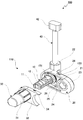
- FIG. 1 is a perspective view of a rotation detection device 100 according to the present embodiment.
- FIG. 2 is an exploded perspective view of the rotation detection device 100.
- the rotation detection device 100 detects a magnetic change caused by the rotation of an axle, detects the number of rotations of the detected axle, etc., and detects the detection signal of the detection device body 110 fixed to the frame of the vehicle etc.
- a cable 40 is provided for transmission to a host device such as an ECU (Electronic Control Unit).
- ECU Electronic Control Unit
- the rotation detection device 100 transmits a detection signal of the detection device main body 110 which detects a magnetic change accompanying the rotation of an axle, and a detection device main body 110 to a host device such as an ECU (Electronic Control Unit).
- a host device such as an ECU (Electronic Control Unit).
- a cable 40 is provided.
- the detection device main body 110 seals the first case 10 together with the second case 20 and the second case 20 that supports the first case 10, the first case 10 and the cable 40. And a case 30.
- the first case 10 is a case that holds the magnetic sensor 11 and the magnet 12 that constitute the magnetic sensor element.
- FIG. 3A is a front side perspective view of the first case 10, and FIG. 3B is a rear side perspective view of the first case 10. As shown in FIG.
- the first case 10 includes a main body portion 15 formed in a substantially elliptic cylindrical shape as a whole.
- the main body portion 15 is integrally formed of resin, and includes a support portion 151, a holding portion 152, and a flange portion 153.
- the support portion 151 is formed in a solid columnar shape.
- the support part 151 is a part supported by the 2nd case 20 and supporting the 1st case 10, as shown in FIG.
- a labyrinth-formed portion 154 having three protrusions 154 a is formed at the end of the support portion 151.
- Each protrusion 154a is not a simple protrusion but has a structure having a significant length in the circumferential direction of the support 151, and in the present embodiment, each protrusion 154a covers the outer periphery of the support 151. It is continuously formed in a ring shape.
- the protrusion 154 a is formed to be thinner toward the tip, and for example, the cross section has a triangular shape.
- the tip end portion of the protruding portion 154a is welded to the second case 20 to be physically integrated.
- the contact surface between the support portion 151 including the plurality of ridges 154 a and the second case 20 described later forms a labyrinth structure whose cross section shows a zigzag shape.
- the holding portion 152 of the main body portion 15 is formed in a chamfered elliptical columnar shape.
- the magnetic sensor 11 is fixed to the tip of the holding portion 152, and the magnet 12 is disposed apart from the magnetic sensor 11.
- the magnetic sensor 11 is configured of, for example, a Hall IC.
- the magnet 12 generates a magnetic field. The strength of the magnetic field at the position of the magnetic sensor 11 changes according to the material of the area facing the rotation detection device 100 and the like. The magnetic sensor 11 detects the strength of this magnetic field.
- the flange portion 153 is disposed at the boundary between the support portion 151 and the holding portion 152 and has a diameter larger than that of the support portion 151 and the holding portion 152.
- the terminal 13 is fixed to the first case 10 in a state in which the connection portion 132 protrudes from the support portion 151.
- the terminal 13 is a fitting for electrically connecting the magnetic sensor 11 and the cable 40.
- FIG. 5A is a front perspective view of the terminal 13
- FIG. 5B is a rear perspective view of the terminal 13.
- the terminal 13 includes a pair of terminal bodies 131.
- the pair of terminal bodies 131 are connected by the connection portion 135.
- the connection portion 135 is for facilitating the handling of the terminal 13 in the manufacturing process.
- the connection portion 135 is formed with an opening 135c for fixing the terminal 13 to a mold at the time of primary molding to be described later. After the primary molding, the connection portion 135 is removed, and the pair of terminal bodies 131 are in a state of being mutually insulated.
- the terminal body 131 is formed of a conductive metal such as copper or brass.
- the terminal main body 131 is molded to the support portion 151 in a state in which both ends are protruded and fixed to the main body portion 15.
- the terminal main body 131 and the resin around it are in close contact, and are kept airtight and watertight.
- One end of the terminal body 131 is formed so as to expand in the shape of “ ⁇ ”, and a connection portion 132 electrically connected to the signal line 42 of the cable 40 is formed.
- the other end of the terminal body 131 is bent in a U-shape in a side view, and a fixing portion 133 is formed at the tip.
- An opening 133 c is formed in the fixing portion 133.
- the U-shaped portion is insert-molded in the interior of the partition wall 155.
- An opening 133 c is formed in the fixing portion 133.
- ribs 134 are formed on the side surfaces in the longitudinal direction of each of the terminal bodies 131.
- the cross section of the terminal main body 131 has a substantially L shape at the rib 134 forming portion.
- the rib 134 is formed by press-molding a part of the terminal main body 131. As shown in FIGS. 5 and 6, the ribs 134 extend from the U-shaped bent portion of each terminal body 131 to the vicinity of the connection portion 132.
- the electrode terminal of the magnetic sensor 11 is electrically connected to the terminal main body 131 by welding, solder or the like through the conductive connection plate 14.
- the first case 10 incorporating the magnetic sensor 11, the magnet 12 and the terminal 13 will be referred to as a primary molded product.
- the second case 20 shown in FIG. 2 is for supporting the first case 10 and the cable 40, and is formed in an elliptical plate shape from resin, and the case holding portion 21, the cable holding portion 22, the fixing portion 23, A plurality of concave portions 24 and an O-ring arrangement portion 25 are provided.
- the second case 20 is formed by insert molding a primary molded product.
- the case holding portion 21 holds the support portion 151 of the first case 10 from the outer periphery, as shown in FIGS. 2 and 4.
- the case holding portion 21 has a concavo-convex shape that matches the shape of the labyrinth formation portion 154 of the first case 10.
- the support portion 151 and the case holding portion 21 form a labyrinth structure in which the interface bends a plurality of times, and the interface between the support portion 151 and the case holding portion 21 constitutes a labyrinth seal, and the airtightness thereof And high watertightness.
- the tip end of the protruding portion 154a is fused with the case holding portion 21 to be integrated. This makes the seal more robust.
- the cable holding portion 22 shown in FIG. 2 holds the cable 40 so as to cover it.
- the insulation coating 41 of the cable 40 is removed, and a signal line 42 such as a copper wire is connected to the connection portion 132 of the terminal main body 131.
- the fixing portion 23 shown in FIG. 2 is a portion used when fixing the rotation detection device 100 to a vehicle or the like, and includes a through hole for passing a bolt or the like.
- the recess 24 is an engagement portion used to hook and fix the third case 30.
- the O-ring disposition portion 25 is a groove in which the O-ring 26 is disposed, and is disposed at the peripheral edge portion of the recess facing the third case 30.
- the arranged O-ring 26 is in close contact with the second case 20 and the third case 30 to seal the joint in an airtight and water-tight manner.
- the third case 30 is a case for sealingly mounting the primary molded product (the first case 10) with the second case 20.
- the third case 30 is formed of a resin such as plastic.
- the third case 30 includes a housing portion 31 and a pedestal portion 32.
- the housing portion 31 has a cavity capable of housing the first case 10 and is formed in a cup shape.
- the pedestal portion 32 is continuous with the housing portion 31 and has an outer shape corresponding to the opening of the second case 20.
- a claw-shaped portion 34 engaged with the recess 24 is formed at a position of the pedestal portion 32 facing the recess 24 of the second case 20.
- the pedestal portion 32 is in pressure contact with the O-ring 26 disposed in the O-ring disposition portion 25. Accordingly, the space between the second case 20 and the third case 30 is maintained airtight and watertight.
- the cable 40 is formed by applying an insulating coating 41 to the pair of signal lines 42.
- the insulation coating 41 at one end of the cable 40 is peeled off, and the signal line 42 is electrically connected to the connection portion 132 of the terminal 13.
- One end of the cable 40 is held by the cable holding portion 22 of the second case 20.
- a connector 43 is connected to the other end of the cable 40.
- the connector 43 is connected to an ECU (not shown).
- the terminal 13 shown in FIG. 5 is mounted in the cavity of a primary molding die (not shown). At this time, the opening 135c of the connection portion 135 is used for fixing to the primary molding die.
- a resin such as plastic is injected into the primary molding die.
- the main body portion 15 including the support portion 151, the holding portion 152, and the flange portion 153 is formed.
- the labyrinth formation part 154 provided with the three flange-like protrusion parts 154a is formed in the front-end
- a part of the terminal main body 131 is molded and fixed by the support portion 151 and the partition wall 155. Under the present circumstances, resin which comprises the support part 151 and the partition wall 155 adheres with the terminal main body 131.
- a part of the resin forms the partition wall 155 and fills the opening 133 c of the fixing portion 133, thereby fixing the fixing portion 133.
- the resin When the resin is filled into the primary molding die, the resin is at high temperature and pressure. As a result, the terminal 13 is heated, pressure is applied, and there is a risk of deformation.
- the rib 134 and the connection portion 135 are formed on the terminal body 131 for preventing deformation.
- the terminal body 131 is reinforced by the rib 134 and the connection portion 135, and the deformation thereof is suppressed.
- the molded body is removed from the primary mold and cooled. Thereby, the intermediate shown in FIG. 6 is obtained. Subsequently, the connection portion 135 of the terminal 13 is removed, and the pair of terminal bodies 131 are electrically separated.
- the magnetic sensor 11 and the magnet 12 are attached to the intermediate product. Furthermore, as shown in FIG. 3B, the electrode terminal of the magnetic sensor 11 and the terminal main body 131 are electrically connected by the connection plate 14 to complete the primary molded product.
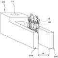
- the secondary molding die 200 shown in FIG. 7 shows a state in which the lid is removed, and for holding the primary molded product and inserting it into the secondary molding die 200, the cable supporting portion 220 for supporting the cable 40.
- the slide unit 210 is provided.
- the slide portion 210 includes support bases 211 a and 211 b disposed at an interval W.
- the distance W between the support bases 211 a and 211 b is larger than the diameter of the holding portion 152 of the first case 10 and smaller than the diameter of the flange portion 153.
- the flange portion 153 of the primary molded product is placed on the support stands 211a and 211b and fixed.
- the cable support portion 220 of the secondary molding die 200 shown in FIG. 7 holds the cable 40 in a state in which the insulation coating 41 at one end is peeled off and the signal wire 42 is exposed.
- the operation unit 212 is pushed to slide the slide unit 210, and the connection unit 132 of the first case 10 is moved until it reaches the position of the signal line 42 of the cable 40.
- the exposed signal line 42 is electrically connected to the connection portion 132 by solder or the like.
- the primary molded product (first case 10) and the cable 40 are covered with a cover portion (not shown) of the secondary molding die 200 to form a cavity, and a resin is press-fitted to form the second case 20 as a resin.
- the resin to be press-fitted is the same as the resin used for molding the first case 10. The resin adheres to the support portion 151 and hardens as the temperature decreases.
- the temperature of the resin to be pressed is high.
- the tip of the ridge portion 154 a of the labyrinth formation portion 154 is thinner.
- the thin tip end of the projection 154a is melted by the temperature of the pressed resin.
- the O-ring 26 is disposed in the O-ring disposition unit 25.
- a secondary molded product including the first case 10 and the second case 20 is completed.
- the resin of the second case 20 is insert-molded in a state where the primary molded product is placed on the slide portion 210 of the secondary molding die 200, so that the primary molded product may come off or be displaced due to the injection pressure of the resin. Etc. can be prevented. Therefore, the positional relationship between the primary molded product and the cable 40 can be stably fixed, and the occurrence of the shape distortion of the rotation detection device 100 can be prevented.
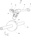
- the operation of rotation detection apparatus 100 having the above configuration will be described with reference to FIG.
- the rotor 320 is fixed coaxially with the axle 310.
- one or more magnets 330 are disposed.
- the rotation detection device 100 is fixed to the frame of the vehicle using the fixing portion 23 so as to face the rotor 320.
- the magnetic sensor 11 converts the strength of the magnetic field accompanying the rotation of the axle 310 into an electrical signal, and outputs a detection signal to the electrode terminal.
- the detection signal is transmitted to the ECU via the connection plate 14, the terminal body 131, the cable 40 and the connector 43.
- a labyrinth seal is formed at the connection portion between the support portion 151 of the first case 10 and the case holding portion 21 of the second case 20, and further, the tip portion of the protruding portion 154a and the case holding portion 21 are welded. In one way. For this reason, it does not enter the inside of the detection device main body 110 via the joint portion of the support portion 151 of the first case 10 and the case holding portion 21 of the second case 20. In this manner, a highly airtight and watertight rotation detection device 100 is obtained.
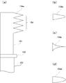
- the labyrinth formation portion 154 shows an example in which three ridges 154 a having a triangular cross-sectional shape are disposed apart from each other, but the labyrinth formation portion 154 is optional as long as it can form a labyrinth structure. It is.
- the ridges 154a may be in contact with each other, and the number is also arbitrary (four in the figure).
- the cross-sectional shape of the protruding portion 154a is not limited to a triangular shape, and as shown in FIGS. 10 (b) to 10 (d), the cross section may be a square, for example, a trapezoidal shape.
- a line forming the outer shape of the cross section may be a curve.
- the cross-sectional shape may be an elliptical shape.
- the distal end portion of the protruding portion 154a is melted at the time of molding of the second case 20, whereby the distal end portion of the protruding portion 154a and the case holding portion 21 of the second case 20 are integrated.
- An example is shown.
- the present invention is not limited to this, and the labyrinth formation portion 154 and the case holding portion 21 of the second case 20 do not have to be integrated.
- the heat of the resin for secondary molding may not melt it. Even in such a case, it is possible to prevent the outside air from entering by the seal with the labyrinth structure.
- the labyrinth formation portion 154 may be provided on the flange portion 153 side of the support portion 151 Alternatively, they may be provided near the center of the support portion 151. In addition, the labyrinth formation portion 154 may be configured on the entire support portion 151.
- the labyrinth forming portion 154 is formed by forming the concave portion in the supporting portion 151. It is also possible. In any case, the labyrinth structure may be formed by forming a concave ridge portion at the interface between the support portion 151 and the case holding portion 21.
- Modification 6 In order to prevent a gap from being formed between the ridge portion 154 a of the first case 10 and the second case 20, it is desirable to increase the injection pressure of the resin forming the second case 20. In addition, it is desirable to increase the temperature of the resin to be inserted. When the viscosity of the resin is increased to accelerate the solidification of the resin, it is necessary to further increase the pressure for inserting the resin. The higher the temperature of the resin and the higher the pressure for inserting the resin, the higher the probability that the terminal 13 is deformed. In the above embodiment, the rib 134 is formed on the side portion in the longitudinal direction of the terminal body 131. As a result, the strength of the terminal body 131 can be increased, and deformation can be prevented. Similarly, it is possible to prevent the terminals 13 from being deformed during secondary forming.
- the rib 134 may not be provided.
- the shape and size of a rib are arbitrary.
- the central portion of the terminal body 131 may be bent to improve its strength.
- the rib 134 is disposed up to the vicinity of the connection portion 132. However, in which position and size of the rib are disposed, deformation does not occur based on the strength of the terminal main body 131. You can adjust it.
- the shapes, sizes, and the like of the terminals 13 and the connection plate 14 are arbitrary as long as they can be stably fixed to the first case 10 and the cable 40 and the magnetic sensor 11 can be electrically connected.
- the magnetic sensor 11 may be directly connected to the cable 40 at the terminal 13 without using a connection plate.
- the secondary molding die 200 having the slide portion 210 is used for secondary molding, but if the first case 10 and the second case 20 can be appropriately molded, the die It is optional.
- the concave portion 24 is provided in the second case 20 in order to hook and fix the second case 20 and the third case 30, but a hole may be provided instead of the concave portion.
- the second case 20 may be provided with a convex portion
- the third case 30 may be provided with a concave portion.
- the type and structure of the magnetic sensor element and the structure on the axle side are not limited to the embodiment and are arbitrary.
- the number of terminal bodies is selected in accordance with the number of electrode terminals of the magnetic sensor. Further, in the case of magnetizing the axle, it is not necessary to arrange the magnet.
- connection part 133 ... fixed part 133c ... opening 134 ... rib 135 ... connection part 135c ... opening 151 ... support part 152 ... holding part 153 ... flange part 154 ... labyrinth formation part 154a-154d ... projecting part 155 ... partition wall 200 secondary molding die 210 slide part 211a, 211b support base 212 operation part 220 cable support part 310 axle shaft 320 rotor 330 magnet
Landscapes
- Physics & Mathematics (AREA)
- General Physics & Mathematics (AREA)
- Transmission And Conversion Of Sensor Element Output (AREA)
Abstract
気密性及び水密性に優れた回転検出装置とその製造方法を提供する。 回転検出装置100は、磁気センサ11と磁石12と磁気センサ11に電気的に接続される端子とを保持する第1ケース10と、端子に電気的に接続されるケーブル40と、ケーブル40を保持した状態で第1ケース10に固定される第2ケース20と、第2ケース20と共に第1ケース10を密封する第3ケース30とを備える。第2ケース20は、第1ケース10の支持部151を外周から保持するケース保持部21を備え、第1ケース10は、支持部151にケース保持部21との接触面に突条部を備え、ラビリンス構造を形成する。
Description
本発明は、回転検出装置とその製造方法に関する。
自動車等の車両には、車軸の回転数を検出する回転検出装置が使用されている。例えば、特許文献1の図4には、先端部分にセンサ素子が組み付けられたホルダと、ホルダの先端部が内装されたケースと、ホルダを介してセンサ素子に接続されたケーブルと、これらの接続部分を被覆する被覆部とを備える車両用の回転検出器が開示されている。
特許文献1に開示された回転検出装置の構造では、ケーブルと周囲の被覆樹脂との間に、わずかに間隙が生じてしまう。この間隙は、ホルダ上端の開口を介して、ホルダの内部空間に連通する。このため、この間隙を介して、ホルダの内部空間と外気との間で空気が流通してしまう。例えば、温度変動により、ホルダの内部圧が外気圧より低くなると、間隙を介して湿気を含む外気がホルダ内に浸入してしまう。ホルダの先端部には、センサ素子が内装されている。このため、湿気がホルダ内に浸入することにより、センサ素子が劣化するおそれがある。同様に、ケーブルが濡れた場合にも同様に、被覆樹脂との間の間隙を介して、ホルダの内部空間に水が浸入するおそれがある。このため、センサ素子を含む内部回路を高気密及び高水密に保護することができる回転検出装置が必要となる。
本発明は、上記の問題を鑑みてなされたものであり、気密性及び水密性に優れた回転検出装置とその製造方法を提供することを目的とする。
上記目的を達成するため、本発明に係る回転検出装置は、
磁気センサと、
前記磁気センサに電気的に接続される端子と、
前記磁気センサ及び前記端子を保持する第1ケースと、
前記端子に電気的に接続されるケーブルと、
前記ケーブルを保持した状態で前記第1ケースに固定される第2ケースと、
を備え、
前記第2ケースは、前記第1ケースの一端を外周から保持する保持部を備え、
前記第1ケースは、前記保持部との接触面に突条部を備える。
磁気センサと、
前記磁気センサに電気的に接続される端子と、
前記磁気センサ及び前記端子を保持する第1ケースと、
前記端子に電気的に接続されるケーブルと、
前記ケーブルを保持した状態で前記第1ケースに固定される第2ケースと、
を備え、
前記第2ケースは、前記第1ケースの一端を外周から保持する保持部を備え、
前記第1ケースは、前記保持部との接触面に突条部を備える。
上記目的を達成するため、本発明に係る回転検出装置の製造方法は、
磁気センサと該磁気センサに電気的に接続された端子とを保持し、突条部を備える第1ケースを形成する工程と、
前記端子にケーブルを電気的に接続する工程と、
前記第1ケースの突条部を備える領域及び前記ケーブルと前記端子との接続部分を覆う第2ケースを樹脂成形する工程と、
前記第2ケースとの間に前記第1ケースを封止するように、前記第2ケースに第3ケースを装着する工程と、を備える。
磁気センサと該磁気センサに電気的に接続された端子とを保持し、突条部を備える第1ケースを形成する工程と、
前記端子にケーブルを電気的に接続する工程と、
前記第1ケースの突条部を備える領域及び前記ケーブルと前記端子との接続部分を覆う第2ケースを樹脂成形する工程と、
前記第2ケースとの間に前記第1ケースを封止するように、前記第2ケースに第3ケースを装着する工程と、を備える。
本発明によれば、回転検出装置の気密性及び水密性を向上することができる。
本発明の実施形態に係る回転検出装置とその製造方法を図面を参照して説明する。
本実施形態に係る回転検出装置は、自動車の車軸の回転数を検出するために装備される。
本実施形態に係る回転検出装置は、自動車の車軸の回転数を検出するために装備される。
図1は、本実施の形態に係る回転検出装置100の斜視図である。図2は、回転検出装置100の展開斜視図である。
回転検出装置100は、車軸の回転に伴う磁気変化を検出し、検出した車軸の回転数等を検出し、車両のフレーム等に固定される検出装置本体110と、検出装置本体110の検出信号をECU(Electronic Control Unit)等の上位装置に伝送するケーブル40を備える。
回転検出装置100は、車軸の回転に伴う磁気変化を検出し、検出した車軸の回転数等を検出し、車両のフレーム等に固定される検出装置本体110と、検出装置本体110の検出信号をECU(Electronic Control Unit)等の上位装置に伝送するケーブル40を備える。
図1に示すように、回転検出装置100は、車軸の回転に伴う磁気変化を検出する検出装置本体110と、検出装置本体110の検出信号をECU(Electronic Control Unit)等の上位装置に伝送するケーブル40を備える。
図2に示すように、検出装置本体110は、第1ケース10と、第1ケース10とケーブル40とを支持する第2ケース20と、第2ケース20と共に第1ケース10を密封する第3ケース30とを備える。
第1ケース10は、磁気センサ素子を構成する磁気センサ11と磁石12とを保持するケースである。
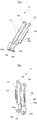
図3(a)は、第1ケース10の表面側斜視図、図3(b)は、第1ケース10の裏面側斜視図である。
図3に示すように、第1ケース10は、全体として略楕円柱状に形成された本体部15を備える。
本体部15は、樹脂により一体に成形され、支持部151と保持部152とフランジ部153とを備える。
支持部151は、中実の柱状に形成されている。支持部151は、図2に示すように、第2ケース20により支持され、第1ケース10を支持する部分である。
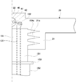
図3,図4に示すように、支持部151の端部には、3つの突条部154aを有するラビリンス形成部154が形成されている。各突条部154aは単純な突起ではなく、支持部151の周方向に有意の長さを有する構造であり、本実施形態では、各突条部154aは、支持部151の外周を覆うようにリング状に連続して形成されている。図4に模式的に示すように、突条部154aは、先端に向けて薄くなるように形成されており、例えば、断面が三角形状をしている。また、突条部154aの先端部は、第2ケース20と溶着しており物理的に一体化している。複数の突条部154aを備える支持部151と後述する第2ケース20との接触面とは、断面がジグザグ状を示すラビリンス構造を形成する。
図3に示すように、本体部15の保持部152は、面取りされた楕円柱状に形成されている。保持部152の先端部には、磁気センサ11が固定され、磁気センサ11と離間して磁石12が配置されている。磁気センサ11は、例えば、ホールIC等から構成される。磁石12は磁場を生成する。回転検出装置100に対向する領域の材質等に応じて、磁気センサ11の位置の磁場の強さが変化する。磁気センサ11は、この磁場の強さを検出する。
フランジ部153は、支持部151と保持部152の境界部に配置され、支持部151及び保持部152よりも大径に形成されている。
また、第1ケース10には、端子13が、その接続部132を支持部151から突出した状態で固定されている。
具体的に説明すると、端子13は、磁気センサ11とケーブル40とを電気的に接続するための金具である。図5(a)は、端子13の表面側斜視図、図5(b)は、端子13の裏面側斜視図である。図示するように、端子13は、一対の端子本体131を備えている。図5では、一対の端子本体131は、接続部135で接続されている。接続部135は、製造工程で端子13の取り扱いを容易にするためのものである。接続部135には、後述する一次成形時に、端子13を金型に固定するための開口135cが形成されている。一次成形後、接続部135は除去され、一対の端子本体131は相互に絶縁された状態となっている。端子本体131は、銅、真鍮等の導電性金属で形成されている。
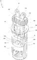
端子本体131は、図3及び図6に示すように、支持部151に、その両端が突出した状態でモールドされて、本体部15に固定されている。端子本体131とその周囲の樹脂とは密着しており、気密且つ水密状態に維持されている。
端子本体131の一端は「ハ」の字状に広がって形成され、ケーブル40の信号線42と電気的に接続される接続部132が形成されている。端子本体131の他端部は、側面視で「コ」の字状に屈曲して形成されて、その先端には、固定部133が形成されている。固定部133には、開口133cが形成されている。図6に示すように、「コ」の字状部は仕切壁155の内部にインサート成形されている。固定部133には、開口133cが形成されている。開口133cを設けたことにより、インサート成形後の端子13の固定がより強固となる。
図5に示すように、端子本体131それぞれの長手方向の側面にはリブ134が形成されている。リブ134形成部分では、端子本体131の断面は、略L字状を有する。リブ134は、端子本体131の一部をプレス成型することにより形成される。図5及び図6に示すように、リブ134は、各端子本体131の、「コ」の字状屈曲部から接続部132の近傍まで延在している。
図3(b)に示すように、磁気センサ11の電極端子は、導電性の接続板14を介して、端子本体131に溶接、半田等により電気的に接続されている。以下、磁気センサ11、磁石12及び端子13を組み込んだ第1ケース10を、一次成形品と呼ぶ。
図2に示す第2ケース20は、第1ケース10とケーブル40とを支持するためのものであり、樹脂により楕円板状に形成され、ケース保持部21、ケーブル保持部22、固定部23、複数の凹部24、Oリング配設部25を備える。第2ケース20は、一次成形品をインサート成形して形成される。
ケース保持部21は、図2及び図4に示すように、第1ケース10の支持部151を外周から保持する。ケース保持部21は、図4に示すように、第1ケース10のラビリンス形成部154の形状に合致する凹凸形状を有する。このため、支持部151とケース保持部21とは、その界面が複数回屈曲するラビリンス構造を形成し、支持部151とケース保持部21との境界面は、ラビリンスシールを構成し、その気密性及び水密性が高い。さらに、突条部154aの先端部がケース保持部21と融着し、一体化している。このため、シールはより強固なものとなっている。
図2に示すケーブル保持部22は、ケーブル40を覆うように保持する。図4に模式的に示す様に、ケーブル保持部22内では、ケーブル40の絶縁被覆41が除去され、銅線等の信号線42が端子本体131の接続部132に接続されている。
図2に示す固定部23は、回転検出装置100を車両等に固定する際に使用される部分であり、ボルト等を通すための貫通穴を備える。
凹部24は、第3ケース30をフック固定するために使用される係合部である。
凹部24は、第3ケース30をフック固定するために使用される係合部である。
Oリング配設部25は、Oリング26を配設する溝であり、第3ケース30に対向する凹み部の周縁部に配置されている。配置されたOリング26は、第2ケース20と第3ケース30とに密着し、接合部を気密及び水密に封止する。
第3ケース30は、一次成形品(第1ケース10)を、第2ケース20との間に密封実装するためのケースである。第3ケース30は、プラスチック等の樹脂で形成されている。第3ケース30は、収容部31と台座部32とを備える。収容部31は、第1ケース10を収容可能な空洞を有し、カップ状に形成されている。台座部32は、収容部31に連続し、第2ケース20の開口に対応する外形を有する。台座部32の、第2ケース20の凹部24と対向する位置には、凹部24に係合するツメ状部34が形成されている。ツメ状部34が凹部24に係合すると、台座部32は、Oリング配設部25に配置されたOリング26に圧接する。これにより、第2ケース20と第3ケース30の間は気密及び水密に維持される。
ケーブル40は、図4に模式的に示すように、一対の信号線42に絶縁被覆41を施して形成されている。ケーブル40の一端の絶縁被覆41は剥がされており、信号線42は端子13の接続部132に電気的に接続される。ケーブル40の一端部は、第2ケース20のケーブル保持部22に保持されている。ケーブル40の他端には、図2に示すように、コネクタ43が接続されている。コネクタ43は、図示しないECUに接続される。
(製造方法)
次に、上記の構成を備える回転検出装置100の製造方法について説明する。
次に、上記の構成を備える回転検出装置100の製造方法について説明する。
(一次成形品の製造工程)
まず、一次成形品、即ち、磁気センサ11,磁石12及び端子13が装着された第1ケース10を製造する工程を説明する。
まず、一次成形品、即ち、磁気センサ11,磁石12及び端子13が装着された第1ケース10を製造する工程を説明する。
図示せぬ一次成形金型のキャビティ内に図5に示す端子13を装着する。このとき、接続部135の開口135cを一次成形金型への固定用に使用する。
次に、プラスチック等の樹脂を一次成形金型に注入する。この工程により図6に示すように、支持部151と保持部152とフランジ部153とを備える本体部15が形成される。支持部151の先端部には、3つのフランジ状の突条部154aを備えるラビリンス形成部154が形成されている。また、端子本体131の一部が支持部151及び仕切壁155によってモールドされて固定される。この際、支持部151及び仕切壁155を構成する樹脂は、端子本体131と密着する。また、樹脂の一部が仕切壁155を構成すると共に固定部133の開口133cを充填し、固定部133が固定される。
一次成形金型に樹脂を充填する際、樹脂は高温高圧である。このため、端子13が加熱されると共に圧力がかかり、変形するおそれがある。本実施形態では、端子本体131に変形防止用にリブ134及び接続部135が形成されている。このリブ134及び接続部135により、端子本体131が補強され、その変形が抑えられる。
成形完了後、成形体が一次成形金型から取り出され、冷却される。これにより、図6に示す中間品が得られる。続いて、端子13の接続部135が除去され、一対の端子本体131が電気的に分離される。
続いて、中間品に、図2及び図3(a)に示すように、磁気センサ11と磁石12とを装着する。さらに、図3(b)に示すように、磁気センサ11の電極端子と端子本体131とを接続板14で電気的に接続し、一次成形品を完成する。
(二次成形品の製造工程)
次に、図7に概要を示す二次成形金型200を用いて、一次成形品とケーブル40と第2ケース20とを一体成型した二次成形品を樹脂成形する。
次に、図7に概要を示す二次成形金型200を用いて、一次成形品とケーブル40と第2ケース20とを一体成型した二次成形品を樹脂成形する。
図7に示す二次成形金型200は、蓋部を取り外した状態を示し、ケーブル40を支持するケーブル支持部220と、一次成形品を保持して二次成形金型200内に挿入するためのスライド部210を備える。
スライド部210は、図8に示すように、間隔Wを置いて配置された支持台211aと211bとを備える。支持台211aと211bとの間隔Wは、第1ケース10の保持部152の径よりも大きく、フランジ部153の径よりも小さい。図8に示すように、一次成形品のフランジ部153を支持台211a,211bに載置し、固定する。
図7に示す二次成形金型200のケーブル支持部220には、一端の絶縁被覆41を剥がされて信号線42がむき出しになった状態のケーブル40が保持される。次に、操作部212を押してスライド部210をスライドさせ、第1ケース10の接続部132がケーブル40の信号線42の位置に達するまで移動させる。
次に、むき出しになっている信号線42を接続部132に半田等で電気的に接続する。次に、二次成形金型200の図示しないカバー部で一次成形品(第1ケース10)とケーブル40とを覆ってキャビティを形成し、樹脂を圧入して第2ケース20を樹脂形成する。なお、圧入する樹脂は、第1ケース10の成形に用いた樹脂と同一である。樹脂は、支持部151に密着した状態で温度の低下とともに固まる。
ここで、圧入する樹脂の温度は高温である。前述のように、ラビリンス形成部154の突条部154aの先端部は薄くなっている。このため、突条部154aの薄い先端部は、圧入された樹脂の温度によって溶融する。溶融した樹脂と圧入された樹脂とが混合することにより、突条部154aの先端部と第2ケース20とは物理的に一体化し、両者の間の気密性及び水密性が高められる。
成形完了後、二次成形品を二次成形金型200を取り出し冷却する。
成形完了後、二次成形品を二次成形金型200を取り出し冷却する。
次に、図2に示すように、Oリング配設部25にOリング26を配設する。こうして、第1ケース10と第2ケース20を含む二次成形品が完成する。
上述したように、二次成形金型200のスライド部210に一次成形品を乗せた状態で第2ケース20の樹脂をインサート成形することにより、樹脂の注入圧力による一次成形品の脱落・位置ずれ等を防止できる。したがって、一次成形品とケーブル40との位置関係を安定的に固定でき、回転検出装置100の形状歪みの発生を防止することができる。
(三次成形品の製造工程)
続いて、第1ケース10を収容するように、第2ケース20の凹部24に第3ケース30のツメ状部34を係止し、第2ケース20に第3ケース30を嵌合して固定する。これにより回転検出装置100が完成する。
続いて、第1ケース10を収容するように、第2ケース20の凹部24に第3ケース30のツメ状部34を係止し、第2ケース20に第3ケース30を嵌合して固定する。これにより回転検出装置100が完成する。
(動作説明)
次に、上記の構成を備える回転検出装置100の動作について、図9を参照して説明する。
図9に示すように、車軸310と同軸にロータ320が固定されている。ロータ320の外周近傍には、1個または複数個の磁石330が配置されている。
次に、上記の構成を備える回転検出装置100の動作について、図9を参照して説明する。
図9に示すように、車軸310と同軸にロータ320が固定されている。ロータ320の外周近傍には、1個または複数個の磁石330が配置されている。
回転検出装置100は、ロータ320に対向するように、固定部23を用いて車両のフレームに固定される。
図2,図3に示すように、磁気センサ11は、車軸310の回転に伴う磁場の強さを電気信号に変換し、検出信号を電極端子に出力する。この検出信号は、接続板14,端子本体131,ケーブル40、コネクタ43を介して、ECUに伝達される。
ここで、湿気を含む外気がケーブル40と第2ケース20の間の間隙を伝い、或いは、ケーブル40の内部を伝い、端子13の接続部132とケーブル40の接続点に浸入したとする。この場合でも、第1ケース10の支持部151は樹脂で充填されているため、湿気が支持部151を介してケース内部に入り込むことはない。また、端子本体131と樹脂とが密着しているので、端子本体131と樹脂との間の間隙を通じて湿気がケースの内部に入り込むこともない。
さらに、第1ケース10の支持部151と第2ケース20のケース保持部21の接続部分はラビリンスシールが形成され、さらに、突条部154aの先端部分とケース保持部21とが溶着して物理的に一体となっている。このため、第1ケース10の支持部151と第2ケース20のケース保持部21の接合部分を介して、検出装置本体110の内部に入り込むこともない。
このようにして、気密性及び水密性の高い回転検出装置100が得られる。
このようにして、気密性及び水密性の高い回転検出装置100が得られる。
(変形例1)
実施形態では、ラビリンス形成部154は、断面三角形状の突条部154aが、3つ、互いに離間して配置される例を示したが、ラビリンス形成部154は、ラビリンス構造を形成できるならば任意である。例えば、図10(a)に示すように、突条部154aは、互いに接していてもよく、また、その数も任意(図では4つ)である。また、突条部154aの断面形状も三角形状に限定されず、図10(b)~(d)に示すように、断面が四角形、例えば、台形形状であってもよい。また、図10(c)に示すように断面の外形を形成する線が曲線であってもよい。また、図10(d)に示すように断面形状が楕円形状であってもよい。
実施形態では、ラビリンス形成部154は、断面三角形状の突条部154aが、3つ、互いに離間して配置される例を示したが、ラビリンス形成部154は、ラビリンス構造を形成できるならば任意である。例えば、図10(a)に示すように、突条部154aは、互いに接していてもよく、また、その数も任意(図では4つ)である。また、突条部154aの断面形状も三角形状に限定されず、図10(b)~(d)に示すように、断面が四角形、例えば、台形形状であってもよい。また、図10(c)に示すように断面の外形を形成する線が曲線であってもよい。また、図10(d)に示すように断面形状が楕円形状であってもよい。
(変形例2)
上記実施の形態においては、突条部154aの先端部分が、第2ケース20を成形時に溶融することにより、突条部154aの先端部と第2ケース20のケース保持部21とが一体化している例を示した。この発明はこれに限定されず、ラビリンス形成部154と第2ケース20のケース保持部21とが一体化する必要はない。例えば、図10(b)に示す断面形状を有する突条部154bを採用する場合、その先端部は比較的厚い。このため、二次成形用の樹脂の熱では溶融しない可能性がある。このような場合でも、ラビリンス構造によるシールにより外気の浸入を防ぐことが可能である。
上記実施の形態においては、突条部154aの先端部分が、第2ケース20を成形時に溶融することにより、突条部154aの先端部と第2ケース20のケース保持部21とが一体化している例を示した。この発明はこれに限定されず、ラビリンス形成部154と第2ケース20のケース保持部21とが一体化する必要はない。例えば、図10(b)に示す断面形状を有する突条部154bを採用する場合、その先端部は比較的厚い。このため、二次成形用の樹脂の熱では溶融しない可能性がある。このような場合でも、ラビリンス構造によるシールにより外気の浸入を防ぐことが可能である。
(変形例3)
上述の説明では、突条部154aが支持部151の周囲に連続したリング状に形成されている場合について説明した。しかし、突条部154aは連続的に形成される必要はない。例えば、図11(a)、(b)に示すように、支持部151の外周にリング状に断続して配置した複数の突条部154aを複数段設け、且つ、突条部154aが交互に重なるように配置する等してもよい。
上述の説明では、突条部154aが支持部151の周囲に連続したリング状に形成されている場合について説明した。しかし、突条部154aは連続的に形成される必要はない。例えば、図11(a)、(b)に示すように、支持部151の外周にリング状に断続して配置した複数の突条部154aを複数段設け、且つ、突条部154aが交互に重なるように配置する等してもよい。
(変形例4)
なお、上記の説明では、ラビリンス形成部154が支持部151の先端付近に形成されている場合について説明したが、ラビリンス形成部154を支持部151のフランジ部153側に設けるようにしてもよいし、支持部151の中央付近に設けるようにしてもよい。また、支持部151の全体にラビリンス形成部154が構成されていてもよい。
なお、上記の説明では、ラビリンス形成部154が支持部151の先端付近に形成されている場合について説明したが、ラビリンス形成部154を支持部151のフランジ部153側に設けるようにしてもよいし、支持部151の中央付近に設けるようにしてもよい。また、支持部151の全体にラビリンス形成部154が構成されていてもよい。
(変形例5)
なお、上記の説明では、支持部151に突条部を形成することによりラビリンス形成部を形成する例について説明したが、支持部151に凹条部を形成することにより、ラビリンス形成部154を形成することも可能である。いずれにしても、支持部151とケース保持部21との界面に、凹突条部を形成することにより、ラビリンス構造を形成すればよい。
なお、上記の説明では、支持部151に突条部を形成することによりラビリンス形成部を形成する例について説明したが、支持部151に凹条部を形成することにより、ラビリンス形成部154を形成することも可能である。いずれにしても、支持部151とケース保持部21との界面に、凹突条部を形成することにより、ラビリンス構造を形成すればよい。
(変形例6)
第1ケース10の突条部154aと第2ケース20との間に隙間ができないようにするためには、第2ケース20を形成する樹脂の注入圧力を高めることが望ましい。また、インサートする樹脂の温度を高くすることが望ましい。樹脂の固化を速めるために樹脂の粘性を高くした場合には、樹脂をインサートする圧力を一層高める必要がある。このように樹脂を高温にするほど、また、樹脂をインサートする圧力を高くするほど、端子13が変形する確率が高くなる。上記実施の形態では、端子本体131の長手方向の側部に、リブ134が形成されている。これにより、端子本体131の強度が増し、変形することを防止できる。同様に、二次成形時に、端子13が変形することを防止できる。
第1ケース10の突条部154aと第2ケース20との間に隙間ができないようにするためには、第2ケース20を形成する樹脂の注入圧力を高めることが望ましい。また、インサートする樹脂の温度を高くすることが望ましい。樹脂の固化を速めるために樹脂の粘性を高くした場合には、樹脂をインサートする圧力を一層高める必要がある。このように樹脂を高温にするほど、また、樹脂をインサートする圧力を高くするほど、端子13が変形する確率が高くなる。上記実施の形態では、端子本体131の長手方向の側部に、リブ134が形成されている。これにより、端子本体131の強度が増し、変形することを防止できる。同様に、二次成形時に、端子13が変形することを防止できる。
ただし、端子13が、樹脂注入時の圧力に耐える強度を有するならば、リブ134をも設けなくてもよい。
また、リブを設ける場合も、リブの形状及びサイズは任意である。例えば、図12(a)、(b)に例示するように、端子本体131の中央部を屈曲させて、その強度を向上するようにしてもよい。
また、実施形態では、リブ134を接続部132の近傍まで配置したが、リブをどの位置に配置するか、どのサイズにするかは、端子本体131の強度に基づいて、変形が発生しないように調整すればよい。
なお、端子13及び接続板14の形状、サイズ等は、第1ケース10に安定してこれらを固定でき、且つ、ケーブル40と磁気センサ11とを電気的に接続できればよく、任意である。例えば、接続板を使用せず、端子13で直接磁気センサ11とケーブル40とを接続するように構成してもよい。
上記実施の形態では、二次成形に、スライド部210を備える二次成形金型200を使用する例を示したが、第1ケース10と第2ケース20を適切に成形できるならば、金型自体は任意である。
また、上記の説明では、第2ケース20と第3ケース30とをフック固定するために、第2ケース20に凹部24を設ける説明をしたが、凹部に変えて穴部を設けるようにしてもよい。また、第2ケース20に凸部を設け、第3ケース30に凹部を設けるようにしてもよい。
磁気センサ素子の例として、ホールICと磁石の組み合わせを使用する例を示したが、磁気センサ素子の種類と構造、さらに、車軸側の構造は、実施形態に限定されず、任意である。例えば、磁気センサ11としてAMR(Anisotropic-Magneto-Resistive)素子を使用することも可能である。なお、磁気センサの電極端子の数に応じて、端子本体の数を選定する。また、車軸を着磁する場合には、磁石を配置しなくてもよい。
10…第1ケース(一次成形品)
11…磁気センサ
12…磁石
13…端子
14…接続板
15…本体部
20…第2ケース
21…ケース保持部
22…ケーブル保持部
23…固定部
24…凹部
25…Oリング配設部
26・・・Oリング
30…第3ケース
31…収容部
32…台座部
34…ツメ状部
40…ケーブル
41…絶縁被覆
42…信号線
43…コネクタ
100…回転検出装置
110…検出装置本体
131…端子本体
132…接続部
133…固定部
133c…開口
134…リブ
135…接続部
135c…開口
151…支持部
152…保持部
153…フランジ部
154…ラビリンス形成部
154a~154d…突条部
155…仕切壁
200…二次成形金型
210…スライド部
211a,211b…支持台
212…操作部
220…ケーブル支持部
310…車軸
320…ロータ
330…磁石
11…磁気センサ
12…磁石
13…端子
14…接続板
15…本体部
20…第2ケース
21…ケース保持部
22…ケーブル保持部
23…固定部
24…凹部
25…Oリング配設部
26・・・Oリング
30…第3ケース
31…収容部
32…台座部
34…ツメ状部
40…ケーブル
41…絶縁被覆
42…信号線
43…コネクタ
100…回転検出装置
110…検出装置本体
131…端子本体
132…接続部
133…固定部
133c…開口
134…リブ
135…接続部
135c…開口
151…支持部
152…保持部
153…フランジ部
154…ラビリンス形成部
154a~154d…突条部
155…仕切壁
200…二次成形金型
210…スライド部
211a,211b…支持台
212…操作部
220…ケーブル支持部
310…車軸
320…ロータ
330…磁石
Claims (8)
- 磁気センサと、
前記磁気センサに電気的に接続される端子と、
前記磁気センサ及び前記端子を保持する第1ケースと、
前記端子に電気的に接続されるケーブルと、
前記ケーブルを保持した状態で前記第1ケースに固定される第2ケースと、
を備え、
前記第2ケースは、前記第1ケースの一端を外周から保持する保持部を備え、
前記第1ケースは、前記保持部との接触面に突条部を備える、
回転検出装置。 - 前記突条部は複数形成され、
前記複数の突条部を含む前記第1ケースと前記第2ケースとの接触面は、ラビリンス構造を形成している、
請求項1に記載の回転検出装置。 - 前記突条部は、先端に向かうにつれて薄く形成されている、
請求項1に記載の回転検出装置。 - 前記突条部の先端部は、前記第2ケースと溶融により一体化している、
請求項3に記載の回転検出装置。 - 前記端子の長手方向に、リブが形成されている、
請求項1から4の何れか一項に記載の回転検出装置。 - 前記端子の先端には、前記ケーブルを接続する接続部が形成されており、
前記リブは、前記接続部まで伸びて形成されている、
請求項5に記載の回転検出装置。 - 前記第2ケースに装着され、前記第2ケースと共に前記第1ケースを封止する第3ケースをさらに備える、
請求項1から6の何れか1項に記載の回転検出装置。 - 磁気センサと該磁気センサに電気的に接続された端子とを保持し、突条部を備える第1ケースを形成する工程と、
前記端子にケーブルを電気的に接続する工程と、
前記第1ケースの突条部を備える領域及び前記ケーブルと前記端子との接続部分を覆う第2ケースを樹脂成形する工程と、
前記第2ケースとの間に前記第1ケースを封止するように、前記第2ケースに第3ケースを装着する工程と、を備える、
回転検出装置の製造方法。
Applications Claiming Priority (2)
| Application Number | Priority Date | Filing Date | Title |
|---|---|---|---|
| JP2017227228 | 2017-11-27 | ||
| JP2017-227228 | 2017-11-27 |
Publications (1)
| Publication Number | Publication Date |
|---|---|
| WO2019102776A1 true WO2019102776A1 (ja) | 2019-05-31 |
Family
ID=66630601
Family Applications (1)
| Application Number | Title | Priority Date | Filing Date |
|---|---|---|---|
| PCT/JP2018/039609 Ceased WO2019102776A1 (ja) | 2017-11-27 | 2018-10-25 | 回転検出装置とその製造方法 |
Country Status (1)
| Country | Link |
|---|---|
| WO (1) | WO2019102776A1 (ja) |
Citations (5)
| Publication number | Priority date | Publication date | Assignee | Title |
|---|---|---|---|---|
| JPH04339261A (ja) * | 1991-02-06 | 1992-11-26 | Jidosha Kiki Co Ltd | 回転速度検出器 |
| JP2000147077A (ja) * | 1998-11-10 | 2000-05-26 | Bosch Braking Systems Co Ltd | 磁気変化検出センサの製造方法及びその製造装置及びその製造方法によって製造された磁気変化検出センサ |
| JP2002257840A (ja) * | 2001-03-01 | 2002-09-11 | Sumitomo Electric Ind Ltd | 回転検出センサ |
| JP2003066057A (ja) * | 2001-08-27 | 2003-03-05 | Nissin Kogyo Co Ltd | 車輪速センサ及びその製造方法 |
| JP2004264213A (ja) * | 2003-03-03 | 2004-09-24 | Hitachi Unisia Automotive Ltd | 回転検出装置 |
-
2018
- 2018-10-25 WO PCT/JP2018/039609 patent/WO2019102776A1/ja not_active Ceased
Patent Citations (5)
| Publication number | Priority date | Publication date | Assignee | Title |
|---|---|---|---|---|
| JPH04339261A (ja) * | 1991-02-06 | 1992-11-26 | Jidosha Kiki Co Ltd | 回転速度検出器 |
| JP2000147077A (ja) * | 1998-11-10 | 2000-05-26 | Bosch Braking Systems Co Ltd | 磁気変化検出センサの製造方法及びその製造装置及びその製造方法によって製造された磁気変化検出センサ |
| JP2002257840A (ja) * | 2001-03-01 | 2002-09-11 | Sumitomo Electric Ind Ltd | 回転検出センサ |
| JP2003066057A (ja) * | 2001-08-27 | 2003-03-05 | Nissin Kogyo Co Ltd | 車輪速センサ及びその製造方法 |
| JP2004264213A (ja) * | 2003-03-03 | 2004-09-24 | Hitachi Unisia Automotive Ltd | 回転検出装置 |
Similar Documents
| Publication | Publication Date | Title |
|---|---|---|
| JP5817941B2 (ja) | 車輪速センサ及びワイヤハーネス | |
| JP5249352B2 (ja) | 磁界センサ | |
| US9107309B2 (en) | Sensor housing for a direct assembly of a wiring harness by machine | |
| JP5898009B2 (ja) | コネクタ | |
| CN108886294B (zh) | 电机和用于制造电机的方法 | |
| JP5910544B2 (ja) | 回路固定部材、回路モジュール、並びに、回路モジュールの接続方法 | |
| JP2013041677A (ja) | コネクタおよびそのコネクタの製造方法 | |
| US10096986B2 (en) | Device for sealing an electrical connection | |
| CN108063327A (zh) | 连接器 | |
| JP2010123513A (ja) | フラットケーブル及びその製造方法、フラットケーブルのコネクタ | |
| JP5846802B2 (ja) | コネクタおよびそのコネクタの製造方法 | |
| US20200240817A1 (en) | Holder for a Sensor Unit | |
| US20200049536A1 (en) | Sensor Arrangement | |
| US20110273854A1 (en) | Magnetic Field Sensor | |
| JP5990116B2 (ja) | コネクタの防水構造 | |
| CN102262969B (zh) | 电气部件 | |
| CN112964891A (zh) | 模块化速度传感器 | |
| JP6813597B2 (ja) | センサ装置及びセンサ装置の製造方法 | |
| US20240162645A1 (en) | Connector | |
| JP6153146B1 (ja) | 回転センサ | |
| US12601617B2 (en) | Composite molded component | |
| US20180123300A1 (en) | Electronic controller | |
| JP2006179377A (ja) | 電気信管点火装置用コネクタ | |
| WO2016143324A1 (ja) | 液面検出装置及びその製造方法 | |
| CN106664807B (zh) | 电设备和具有电设备的连接组件 |
Legal Events
| Date | Code | Title | Description |
|---|---|---|---|
| 121 | Ep: the epo has been informed by wipo that ep was designated in this application |
Ref document number: 18881339 Country of ref document: EP Kind code of ref document: A1 |
|
| NENP | Non-entry into the national phase |
Ref country code: DE |
|
| 122 | Ep: pct application non-entry in european phase |
Ref document number: 18881339 Country of ref document: EP Kind code of ref document: A1 |
|
| NENP | Non-entry into the national phase |
Ref country code: JP |