WO2019098315A1 - 光電変換素子および固体撮像装置 - Google Patents
光電変換素子および固体撮像装置 Download PDFInfo
- Publication number
- WO2019098315A1 WO2019098315A1 PCT/JP2018/042417 JP2018042417W WO2019098315A1 WO 2019098315 A1 WO2019098315 A1 WO 2019098315A1 JP 2018042417 W JP2018042417 W JP 2018042417W WO 2019098315 A1 WO2019098315 A1 WO 2019098315A1
- Authority
- WO
- WIPO (PCT)
- Prior art keywords
- photoelectric conversion
- organic
- electrode
- unit
- layer
- Prior art date
- Legal status (The legal status is an assumption and is not a legal conclusion. Google has not performed a legal analysis and makes no representation as to the accuracy of the status listed.)
- Ceased
Links
Images







Classifications
-
- H—ELECTRICITY
- H10—SEMICONDUCTOR DEVICES; ELECTRIC SOLID-STATE DEVICES NOT OTHERWISE PROVIDED FOR
- H10K—ORGANIC ELECTRIC SOLID-STATE DEVICES
- H10K30/00—Organic devices sensitive to infrared radiation, light, electromagnetic radiation of shorter wavelength or corpuscular radiation
- H10K30/451—Organic devices sensitive to infrared radiation, light, electromagnetic radiation of shorter wavelength or corpuscular radiation comprising a metal-semiconductor-metal [m-s-m] structure
-
- H—ELECTRICITY
- H10—SEMICONDUCTOR DEVICES; ELECTRIC SOLID-STATE DEVICES NOT OTHERWISE PROVIDED FOR
- H10F—INORGANIC SEMICONDUCTOR DEVICES SENSITIVE TO INFRARED RADIATION, LIGHT, ELECTROMAGNETIC RADIATION OF SHORTER WAVELENGTH OR CORPUSCULAR RADIATION
- H10F30/00—Individual radiation-sensitive semiconductor devices in which radiation controls the flow of current through the devices, e.g. photodetectors
- H10F30/20—Individual radiation-sensitive semiconductor devices in which radiation controls the flow of current through the devices, e.g. photodetectors the devices having potential barriers, e.g. phototransistors
-
- H—ELECTRICITY
- H10—SEMICONDUCTOR DEVICES; ELECTRIC SOLID-STATE DEVICES NOT OTHERWISE PROVIDED FOR
- H10F—INORGANIC SEMICONDUCTOR DEVICES SENSITIVE TO INFRARED RADIATION, LIGHT, ELECTROMAGNETIC RADIATION OF SHORTER WAVELENGTH OR CORPUSCULAR RADIATION
- H10F39/00—Integrated devices, or assemblies of multiple devices, comprising at least one element covered by group H10F30/00, e.g. radiation detectors comprising photodiode arrays
- H10F39/10—Integrated devices
- H10F39/12—Image sensors
- H10F39/18—Complementary metal-oxide-semiconductor [CMOS] image sensors; Photodiode array image sensors
-
- H—ELECTRICITY
- H10—SEMICONDUCTOR DEVICES; ELECTRIC SOLID-STATE DEVICES NOT OTHERWISE PROVIDED FOR
- H10F—INORGANIC SEMICONDUCTOR DEVICES SENSITIVE TO INFRARED RADIATION, LIGHT, ELECTROMAGNETIC RADIATION OF SHORTER WAVELENGTH OR CORPUSCULAR RADIATION
- H10F39/00—Integrated devices, or assemblies of multiple devices, comprising at least one element covered by group H10F30/00, e.g. radiation detectors comprising photodiode arrays
- H10F39/10—Integrated devices
- H10F39/12—Image sensors
- H10F39/18—Complementary metal-oxide-semiconductor [CMOS] image sensors; Photodiode array image sensors
- H10F39/182—Colour image sensors
- H10F39/1825—Multicolour image sensors having stacked structure, e.g. NPN, NPNPN or multiple quantum well [MQW] structures
-
- H—ELECTRICITY
- H10—SEMICONDUCTOR DEVICES; ELECTRIC SOLID-STATE DEVICES NOT OTHERWISE PROVIDED FOR
- H10F—INORGANIC SEMICONDUCTOR DEVICES SENSITIVE TO INFRARED RADIATION, LIGHT, ELECTROMAGNETIC RADIATION OF SHORTER WAVELENGTH OR CORPUSCULAR RADIATION
- H10F39/00—Integrated devices, or assemblies of multiple devices, comprising at least one element covered by group H10F30/00, e.g. radiation detectors comprising photodiode arrays
- H10F39/10—Integrated devices
- H10F39/12—Image sensors
- H10F39/191—Photoconductor image sensors
-
- H—ELECTRICITY
- H10—SEMICONDUCTOR DEVICES; ELECTRIC SOLID-STATE DEVICES NOT OTHERWISE PROVIDED FOR
- H10F—INORGANIC SEMICONDUCTOR DEVICES SENSITIVE TO INFRARED RADIATION, LIGHT, ELECTROMAGNETIC RADIATION OF SHORTER WAVELENGTH OR CORPUSCULAR RADIATION
- H10F39/00—Integrated devices, or assemblies of multiple devices, comprising at least one element covered by group H10F30/00, e.g. radiation detectors comprising photodiode arrays
- H10F39/10—Integrated devices
- H10F39/12—Image sensors
- H10F39/199—Back-illuminated image sensors
-
- H—ELECTRICITY
- H10—SEMICONDUCTOR DEVICES; ELECTRIC SOLID-STATE DEVICES NOT OTHERWISE PROVIDED FOR
- H10F—INORGANIC SEMICONDUCTOR DEVICES SENSITIVE TO INFRARED RADIATION, LIGHT, ELECTROMAGNETIC RADIATION OF SHORTER WAVELENGTH OR CORPUSCULAR RADIATION
- H10F39/00—Integrated devices, or assemblies of multiple devices, comprising at least one element covered by group H10F30/00, e.g. radiation detectors comprising photodiode arrays
- H10F39/80—Constructional details of image sensors
- H10F39/803—Pixels having integrated switching, control, storage or amplification elements
-
- H—ELECTRICITY
- H10—SEMICONDUCTOR DEVICES; ELECTRIC SOLID-STATE DEVICES NOT OTHERWISE PROVIDED FOR
- H10F—INORGANIC SEMICONDUCTOR DEVICES SENSITIVE TO INFRARED RADIATION, LIGHT, ELECTROMAGNETIC RADIATION OF SHORTER WAVELENGTH OR CORPUSCULAR RADIATION
- H10F39/00—Integrated devices, or assemblies of multiple devices, comprising at least one element covered by group H10F30/00, e.g. radiation detectors comprising photodiode arrays
- H10F39/80—Constructional details of image sensors
- H10F39/811—Interconnections
-
- H—ELECTRICITY
- H10—SEMICONDUCTOR DEVICES; ELECTRIC SOLID-STATE DEVICES NOT OTHERWISE PROVIDED FOR
- H10K—ORGANIC ELECTRIC SOLID-STATE DEVICES
- H10K30/00—Organic devices sensitive to infrared radiation, light, electromagnetic radiation of shorter wavelength or corpuscular radiation
- H10K30/30—Organic devices sensitive to infrared radiation, light, electromagnetic radiation of shorter wavelength or corpuscular radiation comprising bulk heterojunctions, e.g. interpenetrating networks of donor and acceptor material domains
-
- H—ELECTRICITY
- H10—SEMICONDUCTOR DEVICES; ELECTRIC SOLID-STATE DEVICES NOT OTHERWISE PROVIDED FOR
- H10K—ORGANIC ELECTRIC SOLID-STATE DEVICES
- H10K30/00—Organic devices sensitive to infrared radiation, light, electromagnetic radiation of shorter wavelength or corpuscular radiation
- H10K30/40—Organic devices sensitive to infrared radiation, light, electromagnetic radiation of shorter wavelength or corpuscular radiation comprising a p-i-n structure, e.g. having a perovskite absorber between p-type and n-type charge transport layers
-
- H—ELECTRICITY
- H10—SEMICONDUCTOR DEVICES; ELECTRIC SOLID-STATE DEVICES NOT OTHERWISE PROVIDED FOR
- H10K—ORGANIC ELECTRIC SOLID-STATE DEVICES
- H10K39/00—Integrated devices, or assemblies of multiple devices, comprising at least one organic radiation-sensitive element covered by group H10K30/00
- H10K39/30—Devices controlled by radiation
- H10K39/32—Organic image sensors
-
- H—ELECTRICITY
- H10—SEMICONDUCTOR DEVICES; ELECTRIC SOLID-STATE DEVICES NOT OTHERWISE PROVIDED FOR
- H10K—ORGANIC ELECTRIC SOLID-STATE DEVICES
- H10K85/00—Organic materials used in the body or electrodes of devices covered by this subclass
- H10K85/20—Carbon compounds, e.g. carbon nanotubes or fullerenes
- H10K85/211—Fullerenes, e.g. C60
-
- H—ELECTRICITY
- H10—SEMICONDUCTOR DEVICES; ELECTRIC SOLID-STATE DEVICES NOT OTHERWISE PROVIDED FOR
- H10K—ORGANIC ELECTRIC SOLID-STATE DEVICES
- H10K85/00—Organic materials used in the body or electrodes of devices covered by this subclass
- H10K85/30—Coordination compounds
- H10K85/311—Phthalocyanine
-
- H—ELECTRICITY
- H10—SEMICONDUCTOR DEVICES; ELECTRIC SOLID-STATE DEVICES NOT OTHERWISE PROVIDED FOR
- H10K—ORGANIC ELECTRIC SOLID-STATE DEVICES
- H10K85/00—Organic materials used in the body or electrodes of devices covered by this subclass
- H10K85/60—Organic compounds having low molecular weight
- H10K85/649—Aromatic compounds comprising a hetero atom
- H10K85/657—Polycyclic condensed heteroaromatic hydrocarbons
- H10K85/6576—Polycyclic condensed heteroaromatic hydrocarbons comprising only sulfur in the heteroaromatic polycondensed ring system, e.g. benzothiophene
-
- Y—GENERAL TAGGING OF NEW TECHNOLOGICAL DEVELOPMENTS; GENERAL TAGGING OF CROSS-SECTIONAL TECHNOLOGIES SPANNING OVER SEVERAL SECTIONS OF THE IPC; TECHNICAL SUBJECTS COVERED BY FORMER USPC CROSS-REFERENCE ART COLLECTIONS [XRACs] AND DIGESTS
- Y02—TECHNOLOGIES OR APPLICATIONS FOR MITIGATION OR ADAPTATION AGAINST CLIMATE CHANGE
- Y02E—REDUCTION OF GREENHOUSE GAS [GHG] EMISSIONS, RELATED TO ENERGY GENERATION, TRANSMISSION OR DISTRIBUTION
- Y02E10/00—Energy generation through renewable energy sources
- Y02E10/50—Photovoltaic [PV] energy
- Y02E10/549—Organic PV cells
Definitions
- the present disclosure relates to a photoelectric conversion element using an organic semiconductor material and a solid-state imaging device provided with the same.
- the organic photoelectric conversion element a bulk hetero structure in which a p-type organic semiconductor and an n-type organic semiconductor are mixed is adopted, and the external quantum efficiency is improved.
- the organic photoelectric conversion element has a problem that sufficient external quantum efficiency can not be obtained due to the low conductivity of the organic semiconductor.
- the organic imaging device has a problem that an electrical output signal is easily delayed with respect to incident light.
- Patent Document 1 discloses a photoelectric conversion element using an organic semiconductor compound having horizontal orientation.
- Patent Document 2 discloses an organic thin film solar cell in which an orientation control layer is provided below the i layer.
- Patent Document 3 discloses a method of manufacturing an organic photoelectric conversion element in which the orientation of the photoelectric conversion layer is controlled by forming a film by controlling the substrate temperature.
- a photoelectric conversion element is provided between a first electrode, a second electrode disposed opposite to the first electrode, and a first electrode and a second electrode, and one of the layers is provided in the layer.
- An organic photoelectric conversion layer having a domain of an organic semiconductor material is provided, and the domain of one organic semiconductor material has a percolation structure which longitudinally cuts the organic photoelectric conversion layer in the film thickness direction, and the organic photoelectric conversion layer The domain length in the planar direction is smaller than the domain length in the film thickness direction of the organic photoelectric conversion layer.
- the solid-state imaging device includes the photoelectric conversion element according to an embodiment of the present disclosure as an organic photoelectric conversion unit, in which each pixel includes one or more organic photoelectric conversion units.
- the organic photoelectric conversion layer provided between the first electrode and the second electrode is formed into a domain having a predetermined shape in the layer. It was made to comprise using one organic-semiconductor material.
- the domain of the one organic semiconductor material has a percolation structure which longitudinally cuts the organic photoelectric conversion layer in the film thickness direction, and the domain length in the planar direction of the organic photoelectric conversion layer is smaller than the domain length in the film thickness direction. Thereby, it becomes possible to control appropriately the mixed state of the organic semiconductor material which constitutes the organic photoelectric conversion layer.
- the configuration is made using one organic semiconductor material that forms the domain as described above in the layer.
- the organic semiconductor material which comprises a conversion layer is controlled by the suitable mixed state.
- the external quantum efficiency and the response speed can be improved.
- Embodiment photoelectric conversion element in which an organic photoelectric conversion layer is formed using one organic semiconductor material forming a domain of a predetermined shape
- Configuration of photoelectric conversion element 1-2.
- Method of manufacturing photoelectric conversion element 1-3.
- Action / Effect 2.
- Modified example photoelectric conversion element in which a plurality of organic photoelectric conversion units are stacked
- Application example 4 Example
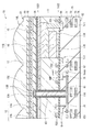
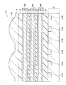
- FIG. 1 illustrates a cross-sectional configuration of a photoelectric conversion element (photoelectric conversion element 10) according to an embodiment of the present disclosure.
- the photoelectric conversion element 10 is, for example, one pixel in a solid-state imaging device (solid-state imaging device 1) such as a backside illuminated type (backside light receiving type) CCD (charge coupled device) image sensor or a CMOS (complementary metal oxide semiconductor) image sensor (Unit pixel P) is configured (see FIG. 8).
- a solid-state imaging device solid-state imaging device
- CCD charge coupled device
- CMOS complementary metal oxide semiconductor
- the photoelectric conversion element 10 is formed by stacking one organic photoelectric conversion unit 11G and two inorganic photoelectric conversion units 11B and 11R in the vertical direction for each unit pixel P.
- the organic photoelectric conversion unit 11G is provided on the back surface (first surface 11S1) side of the semiconductor substrate 11.
- the inorganic photoelectric conversion units 11B and 11R are embedded in the semiconductor substrate 11 and stacked in the thickness direction of the semiconductor substrate 11.
- the organic photoelectric conversion unit 11G is configured to include a p-type semiconductor and an n-type semiconductor, and includes an organic photoelectric conversion layer 16 having a bulk heterojunction structure in the layer.
- the bulk heterojunction structure is a p / n junction surface formed by mixing a p-type semiconductor and an n-type semiconductor.
- the organic photoelectric conversion unit 11G and the inorganic photoelectric conversion units 11B and 11R selectively detect light in wavelength bands different from each other to perform photoelectric conversion. Specifically, the organic photoelectric conversion unit 11G acquires a green (G) color signal. In the inorganic photoelectric conversion units 11B and 11R, color signals of blue (B) and red (R) are obtained based on the difference in absorption coefficient. Thereby, in the photoelectric conversion element 10, a plurality of types of color signals can be obtained in one pixel without using a color filter.
- the semiconductor substrate 11 is made of, for example, an n-type silicon (Si) substrate, and has a p-well 61 in a predetermined region.
- various floating diffusions (floating diffusion layers) FD for example, FD1, FD2, FD3
- various transistors Tr for example, vertical transistors (for example, vertical transistors) (for example, vertical transistors) are provided on the second surface (surface of the semiconductor substrate 11) 11S2 of the p well 61.
- a transfer transistor Tr1, a transfer transistor Tr2, an amplifier transistor (modulation element) AMP and a reset transistor RST, and a multilayer interconnection 70 are provided.
- the multilayer wiring 70 has, for example, a configuration in which the wiring layers 71, 72, 73 are stacked in the insulating layer 74.
- peripheral circuits (not shown) including logic circuits and the like are provided in the peripheral portion of the semiconductor substrate 11.
- the first surface 11S1 side of the semiconductor substrate 11 is referred to as a light incident surface S1
- the second surface 11S2 side is referred to as a wiring layer side S2.
- the inorganic photoelectric conversion units 11B and 11R are formed of, for example, photodiodes of the PIN (Positive Intrinsic Negative) type, and each have a pn junction in a predetermined region of the semiconductor substrate 11.
- the inorganic photoelectric conversion parts 11B and 11R make it possible to disperse light in the longitudinal direction by utilizing the fact that the wavelength bands absorbed in the silicon substrate differ according to the incident depth of light.
- the inorganic photoelectric conversion unit 11B selectively detects blue light to accumulate signal charges corresponding to blue, and is disposed at a depth at which blue light can be efficiently photoelectrically converted.
- the inorganic photoelectric conversion unit 11R selectively detects red light and stores signal charges corresponding to red, and is disposed at a depth at which red light can be efficiently photoelectrically converted.
- Blue (B) is a color corresponding to, for example, a wavelength band of 450 nm to 495 nm
- red (R) is a color corresponding to a wavelength band of, for example, 620 nm to 750 nm.
- the inorganic photoelectric conversion units 11 ⁇ / b> B and 11 ⁇ / b> R only need to be able to detect light in a wavelength band of a part or all of the respective wavelength bands.
- each of the inorganic photoelectric conversion unit 11B and the inorganic photoelectric conversion unit 11R has, for example, ap + region to be a hole storage layer and an n region to be an electron storage layer. (Having a layered structure of pnp).
- the n region of the inorganic photoelectric conversion unit 11B is connected to the vertical transistor Tr1.
- the p + region of the inorganic photoelectric conversion unit 11B is bent along the vertical transistor Tr1 and is connected to the p + region of the inorganic photoelectric conversion unit 11R.
- the floating diffusions floating diffusion layers
- FD1, FD2, and FD3 the vertical transistor (transfer transistor) Tr1, the transfer transistor Tr2, and the amplifier transistor A modulation element) AMP and a reset transistor RST are provided.
- the vertical transistor Tr1 is a transfer transistor that transfers the signal charge (here, electrons) corresponding to blue generated and accumulated in the inorganic photoelectric conversion unit 11B to the floating diffusion FD1. Since the inorganic photoelectric conversion unit 11B is formed at a deep position from the second surface 11S2 of the semiconductor substrate 11, it is preferable that the transfer transistor of the inorganic photoelectric conversion unit 11B be configured by the vertical transistor Tr1.
- the transfer transistor Tr2 transfers the signal charge (here, electrons) generated in the inorganic photoelectric conversion unit 11R and corresponding to the accumulated red to the floating diffusion FD2, and is formed of, for example, a MOS transistor.
- the amplifier transistor AMP is a modulation element that modulates the amount of charge generated in the organic photoelectric conversion unit 11G to a voltage, and is formed of, for example, a MOS transistor.
- the reset transistor RST is for resetting the charge transferred from the organic photoelectric conversion unit 11G to the floating diffusion FD3, and is made of, for example, a MOS transistor.
- the lower first contact 75, the lower second contact 76 and the upper contact 13B are made of, for example, a doped silicon material such as PDAS (Phosphorus Doped Amorphous Silicon) or aluminum (Al), tungsten (W), titanium (Ti) And metal materials such as cobalt (Co), hafnium (Hf), tantalum (Ta) and the like.
- PDAS Phosphorus Doped Amorphous Silicon
- Al aluminum
- Ti titanium
- metal materials such as cobalt (Co), hafnium (Hf), tantalum (Ta) and the like.
- the organic photoelectric conversion unit 11G On the first surface 11S1 side of the semiconductor substrate 11, an organic photoelectric conversion unit 11G is provided.
- the organic photoelectric conversion unit 11G has, for example, a configuration in which the lower electrode 15, the organic photoelectric conversion layer 16 and the upper electrode 17 are stacked in this order from the side of the first surface 11S1 of the semiconductor substrate 11.
- the lower electrode 15 is formed separately for each photoelectric conversion element 10, for example.
- the organic photoelectric conversion layer 16 and the upper electrode 17 are provided as a continuous layer common to the plurality of photoelectric conversion elements 10.
- the organic photoelectric conversion unit 11G absorbs green light corresponding to a part or all of a selective wavelength band (for example, 450 nm or more and 650 nm or less) to generate an electron-hole pair It is.
- a selective wavelength band for example, 450 nm or more and 650 nm or less
- interlayer insulating layers 12 and 14 are stacked in this order from the semiconductor substrate 11 side between the first surface 11S1 of the semiconductor substrate 11 and the lower electrode 15.
- the interlayer insulating layer has, for example, a configuration in which a layer (fixed charge layer) 12A having a fixed charge and a dielectric layer 12B having an insulating property are stacked.
- a protective layer 18 is provided on the upper electrode 17. Above the protective layer 18, an on-chip lens layer 19 that constitutes the on-chip lens 19 L and also serves as a planarization layer is disposed.
- a through electrode 63 is provided between the first surface 11S1 and the second surface 11S2 of the semiconductor substrate 11.
- the organic photoelectric conversion unit 11G is connected to the gate Gamp of the amplifier transistor AMP and the floating diffusion FD3 via the through electrode 63.
- the charge generated in the organic photoelectric conversion unit 11G on the first surface 11S1 side of the semiconductor substrate 11 is favorably transferred to the second surface 11S2 side of the semiconductor substrate 11 via the through electrode 63. It is possible to improve the characteristics.
- the through electrodes 63 are provided, for example, for each of the organic photoelectric conversion units 11G of the photoelectric conversion element 10.
- the through electrode 63 functions as a connector between the organic photoelectric conversion unit 11G and the gate Gamp of the amplifier transistor AMP and the floating diffusion FD3, and also serves as a transmission path of charges generated in the organic photoelectric conversion unit 11G.
- the lower end of the through electrode 63 is connected to, for example, the connection portion 71A in the wiring layer 71, and the connection portion 71A and the gate Gamp of the amplifier transistor AMP are connected via the lower first contact 75.
- the connection portion 71A and the floating diffusion FD3 are connected to the lower electrode 15 via the lower second contact 76.
- the penetration electrode 63 was shown as cylindrical shape, it is good also as taper shape not only in this, for example.
- a reset gate Grst of the reset transistor RST is disposed.
- the charge accumulated in the floating diffusion FD3 can be reset by the reset transistor RST.
- the photoelectric conversion element 10 of the present embodiment light incident on the organic photoelectric conversion unit 11 G from the upper electrode 17 side is absorbed by the organic photoelectric conversion layer 16.
- the excitons generated by this move to the interface between the electron donor and the electron acceptor constituting the organic photoelectric conversion layer 16 and are separated into excitons, that is, dissociated into electrons and holes.
- the charges (electrons and holes) generated here are diffused by the carrier concentration difference, or by the internal electric field due to the work function difference between the anode (here, the upper electrode 17) and the cathode (here, the lower electrode 15). Each is transported to a different electrode and detected as a photocurrent. Also, by applying a potential between the lower electrode 15 and the upper electrode 17, the transport direction of electrons and holes can be controlled.
- the organic photoelectric conversion unit 11G absorbs green light corresponding to a part or all of a selective wavelength band (for example, 450 nm or more and 650 nm or less) to generate an electron-hole pair It is.
- a selective wavelength band for example, 450 nm or more and 650 nm or less
- the lower electrode 15 is provided in a region that covers the light receiving surfaces of the inorganic photoelectric conversion units 11B and 11R formed in the semiconductor substrate 11 so as to face the light receiving surfaces.
- the lower electrode 15 is made of a light-transmitting conductive film, and is made of, for example, ITO (indium tin oxide).
- ITO indium tin oxide
- zinc oxide based material for example, aluminum zinc oxide (AZO) to which aluminum (Al) is added as a dopant, gallium zinc oxide (GZO) to which gallium (Ga) is added, and indium zinc oxide to which indium (In) is added (IZO).
- AZO aluminum zinc oxide
- GZO gallium zinc oxide
- IZO indium zinc oxide to which indium (In) is added
- CuI, InSbO 4, ZnMgO, CuInO 2, MgIN 2 O 4, CdO may be used ZnSnO 3, and the like.
- the organic photoelectric conversion layer 16 converts light energy into electrical energy.
- the organic photoelectric conversion layer 16 is configured to include, for example, two or more types of organic semiconductor materials, and is preferably configured to include, for example, one or both of a p-type semiconductor and an n-type semiconductor.
- the organic photoelectric conversion layer 16 is composed of two types of organic semiconductor materials, a p-type semiconductor and an n-type semiconductor, the p-type semiconductor and the n-type semiconductor are, for example, one of which is transparent to visible light
- the other material is a material that photoelectrically converts light of a selective wavelength range (for example, 450 nm or more and 650 nm or less).
- the organic photoelectric conversion layer 16 is made of three kinds of organic materials: a material (light absorber) that photoelectrically converts light in a selective wavelength range, and an n-type semiconductor and a p-type semiconductor having transparency to visible light. It is preferable that it is comprised by the semiconductor material.
- the organic photoelectric conversion layer 16 has a bulk heterostructure in which the plurality of organic semiconductor materials are randomly mixed in the layer.
- FIG. 2 represents typically an example of the mixed state of each organic-semiconductor material in the layer of the organic photoelectric converting layer 16 of this Embodiment.
- the organic photoelectric conversion layer 16 as shown in FIG. 2, for example, the above-mentioned three types of organic semiconductor materials (light absorber, p-type semiconductor and n-type semiconductor) are randomly mixed.
- grains for example, a grain Gc of a light absorber and a grain Gn of an n-type semiconductor are formed.
- the layer has a domain (for example, domain Dp) of at least one organic semiconductor material (for example, p-type semiconductor (one organic semiconductor material)) of a plurality of types of organic semiconductor materials in a layer.
- a domain is, for example, a region in which one organic semiconductor material is continuously arranged.
- domains other than the p-type semiconductor for example, an n-type semiconductor or a light absorber
- the domain may be configured to include two or more organic semiconductor materials.
- the domain Dp of the p-type semiconductor in the present embodiment preferably has a percolation structure that cuts the organic photoelectric conversion layer 16 longitudinally in the film thickness direction (Y-axis direction). Furthermore, the domain Dp of the p-type semiconductor preferably has a shape in which the length (domain length) of the domain in the planar direction (for example, the X axis direction) is smaller than the domain length in the film thickness direction. That is, it is preferable that the p-type semiconductor form a domain Dp extending in the p film thickness direction of the organic photoelectric conversion layer 16.
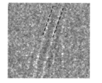
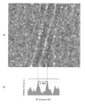
- FIG. 3 shows an image (TEM image) of the organic photoelectric conversion layer 16 (experimental example 1 described later) manufactured using the p-type semiconductor forming the domain as described above under a defocus condition by a transmission electron microscope
- the interference fringes are observed due to the occurrence of phase contrast due to the period of the major axis direction of the p-type semiconductor molecule forming the domain and the wave property of electrons. That is, in the two or more lines constituting the interference fringes, a pair of adjacent lines respectively correspond to a molecular cycle in the long axis direction of the p-type semiconductor molecule.
- the interference fringes extend in the organic photoelectric conversion layer 16 substantially in the film thickness direction, and the length thereof is preferably 20 nm or more. Further, specifically, preferably, the angle between the interference fringes and the electrode surface of the lower electrode 15 is greater than 45 ° and not more than 90 °.
- the distance between the two lines is, for example, preferably within ⁇ 50%, more preferably within ⁇ 30%, of the molecular length of the p-type semiconductor. That is, p-type semiconductors are periodically stacked in the same direction between two lines forming the interference fringes.
- the molecular length of the p-type semiconductor is the length of the molecule in the long axis direction of the p-type semiconductor.
- the organic photoelectric conversion layer 16 is composed of two types of organic semiconductor materials of n-type semiconductor and p-type semiconductor, or three types of organic semiconductor materials of light absorber, n-type semiconductor and p-type semiconductor.
- the layer has a junction surface (p / n junction surface) between a p-type semiconductor and an n-type semiconductor.
- the light absorber has, for example, a maximum absorption wavelength in the range of 450 nm to 650 nm.
- a p-type semiconductor relatively functions as an electron donor (donor), and for example, it is preferable to use a material having a hole transportability.
- An n-type semiconductor relatively functions as an electron acceptor (acceptor), and for example, it is preferable to use a material having an electron transporting property.
- the organic photoelectric conversion layer 16 provides a place where excitons generated upon absorption of light are separated into electrons and holes. Specifically, the interface between the electron donor and the electron acceptor (p At the / n junction surface), excitons are separated into electrons and holes.
- the thickness of the organic photoelectric conversion layer 16 is, for example, 50 nm to 500 nm.
- the surface roughness of the interface between the organic photoelectric conversion layer 16 and the upper electrode 17 is preferably 10 nm or less.
- the present invention is not limited to this.
- an n-type semiconductor may form the domain.
- the upper electrode 17 is made of a conductive film having the same light transmittance as the lower electrode 15.
- the upper electrode 17 may be separated for each pixel or may be formed as an electrode common to each pixel.
- the thickness of the upper electrode 17 is, for example, 10 nm to 200 nm.
- organic photoelectric conversion layer 16 and the lower electrode 15 may be provided between the organic photoelectric conversion layer 16 and the upper electrode 17.
- an undercoat film, a hole transport layer, an electron blocking film, an organic photoelectric conversion layer 16, a hole blocking film, a buffer film, an electron transport layer, a work function adjustment film, etc. in order from the lower electrode 15 side May be stacked.
- the fixed charge layer 12A may be a film having a positive fixed charge or a film having a negative fixed charge.
- Examples of the material of the film having a negative fixed charge include hafnium oxide, aluminum oxide, zirconium oxide, tantalum oxide, titanium oxide and the like.
- Materials other than the above include lanthanum oxide, praseodymium oxide, cerium oxide, neodymium oxide, promethium oxide, samarium oxide, europium oxide, gadolinium oxide, terbium oxide, dysprosium oxide, hole oxide lithium, thulium oxide, ytterbium oxide, lutetium oxide
- An yttrium oxide, an aluminum nitride film, a hafnium oxynitride film, an aluminum oxynitride film, or the like may be used.
- the fixed charge layer 12A may have a configuration in which two or more types of films are stacked. Thereby, for example, in the case of a film having a negative fixed charge, it is possible to further enhance the function as a hole storage layer.
- the material of the dielectric layer 12B is not particularly limited, it is formed of, for example, a silicon oxide film, TEOS, a silicon nitride film, a silicon oxynitride film, or the like.
- the interlayer insulating layer 14 is formed of, for example, a single layer film made of one of silicon oxide, silicon nitride and silicon oxynitride (SiON) or a laminated film made of two or more of these. .
- the protective layer 18 is made of a light transmitting material, and for example, a single layer film made of any one of silicon oxide, silicon nitride, silicon oxynitride and the like, or a laminated film made of two or more of them. It is composed of The thickness of the protective layer 18 is, for example, 100 nm to 30000 nm.
- An on-chip lens layer 19 is formed on the protective layer 18 so as to cover the entire surface.
- the on-chip lens 19L condenses the light incident from above on the light receiving surfaces of the organic photoelectric conversion unit 11G and the inorganic photoelectric conversion units 11B and 11R.
- the multilayer wiring 70 is formed on the second surface 11S2 side of the semiconductor substrate 11, the light receiving surfaces of the organic photoelectric conversion unit 11G and the inorganic photoelectric conversion units 11B and 11R are arranged close to each other. It is possible to reduce the variation in sensitivity among the respective colors depending on the F value of the on-chip lens 19L.
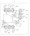
- FIG. 4 is a configuration example of a photoelectric conversion element having a pixel in which a plurality of photoelectric conversion units (for example, the inorganic photoelectric conversion units 11B and 11R and the organic photoelectric conversion unit 11G) to which the technology according to the present disclosure can be applied. It is the top view shown. That is, FIG. 4 shows, for example, an example of a planar configuration of a unit pixel P constituting the pixel unit 1a shown in FIG.
- a unit pixel P is a red photoelectric conversion unit (inorganic photoelectric conversion unit 11R in FIG. 1) that photoelectrically converts light of each wavelength of R (Red), G (Green) and B (Blue), and a blue photoelectric conversion unit (figure The inorganic photoelectric conversion unit 11B) and the green photoelectric conversion unit (the organic photoelectric conversion unit 11G in FIG. 1) (both are not shown in FIG. 4) in 3 are, for example, the light receiving surface (light incident surface S1 in FIG. 1) side
- the photoelectric conversion regions 1100 are stacked in three layers in the order of the green photoelectric conversion unit, the blue photoelectric conversion unit, and the red photoelectric conversion unit.
- the unit pixel P reads out charges corresponding to light of respective wavelengths of RGB from the red photoelectric conversion unit, the green photoelectric conversion unit, and the blue photoelectric conversion unit as a Tr group 1110, Tr group 1120 and Tr as charge readout units. It has a group 1130.
- spectral separation in the vertical direction that is, in each layer as a red photoelectric conversion unit, a green photoelectric conversion unit, and a blue photoelectric conversion unit stacked in the photoelectric conversion region 1100 Spectroscopy of the light.
- the Tr group 1110, the Tr group 1120, and the Tr group 1130 are formed around the photoelectric conversion region 1100.
- the Tr group 1110 outputs, as pixel signals, signal charges corresponding to the R light generated and accumulated in the red photoelectric conversion unit.
- the Tr group 1110 includes a transfer Tr (MOS FET) 1111, a reset Tr 1112, an amplification Tr 1113, and a selection Tr 1114.
- the Tr group 1120 outputs a signal charge corresponding to the B light generated and accumulated in the blue photoelectric conversion unit as a pixel signal.
- the Tr group 1120 includes a transfer Tr 1121, a reset Tr 1122, an amplification Tr 1123, and a selection Tr 1124.
- the Tr group 1130 outputs, as pixel signals, signal charges corresponding to the G light generated and accumulated in the green photoelectric conversion unit.
- the Tr group 1130 includes a transfer Tr 1131, a reset Tr 1132, an amplification Tr 1133 and a selection Tr 1134.
- the transfer Tr 1111 is configured of a gate G, source / drain regions S / D, and FD (floating diffusion) 1115 (source / drain regions being).
- the transfer Tr 1121 includes a gate G, source / drain regions S / D, and an FD 1125.
- the transfer Tr 1131 is composed of a gate G, a green photoelectric conversion unit (a source / drain region S / D connected to it) in the photoelectric conversion region 1100, and an FD 1135.
- the source / drain region of the transfer Tr 1111 is connected to the red photoelectric conversion unit in the photoelectric conversion region 1100, and the source / drain region S / D of the transfer Tr 1121 is connected to the blue photoelectric conversion unit in the photoelectric conversion region 1100. It is connected.
- Reset Trs 1112, 1132 and 1122, amplifications Tr 1113, 1133 and 1123 and selection Trs 1114, 1134 and 1124 all have a gate G and a pair of source / drain regions S / D arranged to sandwich the gate G. It consists of
- the FDs 1115 1135 1125 are respectively connected to the source / drain regions S / D that are the sources of the reset Trs 1112 1132 1122, and are also connected to the gate G of the amplification Trs 1113 1133 1123 respectively.
- a power source Vdd is connected to the common source / drain region S / D in each of the reset Tr 1112 and the amplification Tr 1113, the reset Tr 1132 and the amplification Tr 1133, and the reset Tr 1122 and the amplification Tr 1123.
- a VSL (vertical signal line) is connected to source / drain regions S / D which are sources of the selection Trs 1114, 1134 and 1124.
- the technology according to the present disclosure can be applied to the photoelectric conversion element as described above.
- the photoelectric conversion element 10 of the present embodiment can be manufactured, for example, as follows.
- FIG. 5 and 6 show the method of manufacturing the photoelectric conversion element 10 in the order of steps.
- a p well 61 is formed in the semiconductor substrate 11 as a well of the first conductivity type, and the inorganic of the second conductivity type (for example, n type) is formed in the p well 61.
- the photoelectric conversion units 11B and 11R are formed. In the vicinity of the first surface 11S1 of the semiconductor substrate 11, ap + region is formed.
- the gate insulating layer 62 the vertical transistor Tr1, the transfer transistor Tr2, the amplifier A gate interconnection layer 64 including the gates of the transistor AMP and the reset transistor RST is formed.
- the vertical transistor Tr1, the transfer transistor Tr2, the amplifier transistor AMP, and the reset transistor RST are formed.
- a multilayer wiring 70 including the lower first contact 75, the lower second contact 76, the wiring layers 71 to 73 including the connecting portion 71A, and the insulating layer 74 is formed on the second surface 11S2 of the semiconductor substrate 11.
- an SOI (Silicon on Insulator) substrate in which the semiconductor substrate 11, a buried oxide film (not shown), and a holding substrate (not shown) are stacked is used.
- the buried oxide film and the holding substrate are bonded to the first surface 11S1 of the semiconductor substrate 11, although not shown in FIG. After ion implantation, annealing is performed.
- a supporting substrate (not shown) or another semiconductor substrate or the like is bonded to the second surface 11S2 side (multilayer wiring 70 side) of the semiconductor substrate 11 and vertically inverted. Subsequently, the semiconductor substrate 11 is separated from the buried oxide film and the holding substrate of the SOI substrate, and the first surface 11S1 of the semiconductor substrate 11 is exposed.
- the above steps can be performed by techniques used in a normal CMOS process such as ion implantation and CVD (Chemical Vapor Deposition).
- the semiconductor substrate 11 is processed from the first surface 11S1 side by dry etching, for example, to form an annular opening 63H.
- the depth of the opening 63H penetrates from the first surface 11S1 to the second surface 11S2 of the semiconductor substrate 11 and reaches, for example, the connection portion 71A, as shown in FIG.
- a negative fixed charge layer 12A is formed on the side surface of the first surface 11S1 of the semiconductor substrate 11 and the opening 63H.
- Two or more types of films may be stacked as the negative fixed charge layer 12A. Thereby, the function as the hole accumulation layer can be further enhanced.
- the dielectric layer 12B is formed.
- a conductor is embedded in the opening 63H to form the through electrode 63.
- the conductor for example, in addition to doped silicon materials such as PDAS (Phosphorus Doped Amorphous Silicon), aluminum (Al), tungsten (W), titanium (Ti), cobalt (Co), hafnium (Hf) and tantalum can be used.
- PDAS Phosphorus Doped Amorphous Silicon
- Al aluminum
- Ti tungsten
- Ti titanium
- hafnium (Hf) and tantalum can be used.
- a metal material such as (Ta) can be used.
- the lower electrode 15 and the through electrode 63 are formed on the dielectric layer 12B and the pad portion 13A.
- the upper contact 13B and the pad portion 13C which electrically connect are formed on the interlayer insulating layer 14 provided on the pad portion 13A.
- the lower electrode 15, the organic photoelectric conversion layer 16, the upper electrode 17 and the protective layer 18 are formed in this order on the interlayer insulating layer 14.
- the organic photoelectric conversion layer 16 is formed, for example, by using the above-mentioned three types of organic semiconductor materials, for example, using a vacuum evaporation method.
- an on-chip lens layer 19 having a plurality of on-chip lenses 19L is provided on the surface.
- the photoelectric conversion element 10 shown in FIG. 1 is completed.
- organic layer for example, an electron blocking layer etc.
- it is continuously formed (in a vacuum consistent process) in a vacuum step. It is desirable to do.
- a film-forming method of the organic photoelectric conversion layer 16 you may use not only the method using the vacuum evaporation method necessarily but another method, for example, a spin coat technique, printing technique, etc.
- the photoelectric conversion element 10 when light enters the organic photoelectric conversion unit 11G through the on-chip lens 19L, the light passes through the organic photoelectric conversion unit 11G and the inorganic photoelectric conversion units 11B and 11R in this order, and the passage process The photoelectric conversion is performed for each of green, blue and red color lights.
- the signal acquisition operation of each color will be described.
- the organic photoelectric conversion unit 11G is connected to the gate Gamp of the amplifier transistor AMP and the floating diffusion FD3 via the through electrode 63. Therefore, electrons of the electron-hole pairs generated in the organic photoelectric conversion unit 11G are extracted from the lower electrode 15 side, transferred to the second surface 11S2 side of the semiconductor substrate 11 through the through electrode 63, and floating diffusion It is accumulated in FD3. At the same time, the charge amount generated in the organic photoelectric conversion unit 11G is modulated to a voltage by the amplifier transistor AMP.
- the reset gate Grst of the reset transistor RST is disposed next to the floating diffusion FD3. As a result, the charge accumulated in the floating diffusion FD3 is reset by the reset transistor RST.
- the organic photoelectric conversion unit 11G is connected not only to the amplifier transistor AMP but also to the floating diffusion FD3 via the through electrode 63, the charge accumulated in the floating diffusion FD3 is easily reset by the reset transistor RST. It is possible to
- the orientation of molecules is important for the conduction of an organic semiconductor, and the same applies to an organic photoelectric conversion element having a bulk heterostructure.
- the organic semiconductor preferably has a horizontal orientation with respect to the substrate. For this reason, as described above, various efforts have been made to improve the horizontal orientation of the organic semiconductor constituting the organic photoelectric conversion layer.
- the organic photoelectric conversion layer 16 is configured using an organic semiconductor material (one organic semiconductor material) that forms a domain (for example, domain Dp) of a predetermined shape in the layer.
- an organic semiconductor having a percolation structure which longitudinally cuts the organic photoelectric conversion layer 16 in the film thickness direction and forming a domain having a shape in which the length of the domain in the planar direction is smaller than the length of the domain in the film thickness direction It was made to form the organic photoelectric converting layer 16 containing a material. Thereby, it is possible to appropriately control the mixed state of the organic semiconductor material in the organic photoelectric conversion layer.
- the photoelectric conversion element 10 of this Embodiment uses the organic semiconductor material (for example, p-type semiconductor) of one which forms the domain as mentioned above in the organic photoelectric conversion layer 16 in the organic photoelectric conversion layer 16 I configured it.
- the organic semiconductor material for example, the n-type semiconductor and the light absorber in addition to the p-type semiconductor described above
- the organic photoelectric conversion layer 16 is controlled to an appropriate mixed state.
- the external quantum efficiency and the response speed can be improved.
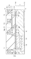
- FIG. 7 illustrates a cross-sectional configuration of a photoelectric conversion element (photoelectric conversion element 20) according to a modification of the present disclosure.
- the photoelectric conversion element 20 is, for example, one unit pixel P in a solid-state imaging element (solid-state imaging device 1) such as a backside illuminated CCD image sensor or a CMOS image sensor, similarly to the photoelectric conversion element 10 of the above-described embodiment and the like.
- solid-state imaging device 1 solid-state imaging device 1
- the photoelectric conversion element 20 of this modification has a configuration in which a red photoelectric conversion unit 40R, a green photoelectric conversion unit 40G, and a blue photoelectric conversion unit 40B are stacked in this order on a silicon substrate 81 via an insulating layer 82.
- Each of the red photoelectric conversion unit 40R, the green photoelectric conversion unit 40G, and the blue photoelectric conversion unit 40B is between the pair of electrodes, specifically, between the first electrode 41R and the second electrode 43R, the first electrode 41G and the first
- the organic photoelectric conversion layers 42R, 42G, and 42B are provided between the two electrodes 43G and between the first electrode 41B and the second electrode 43B, respectively.
- each of the organic photoelectric conversion layers 42R, 42G, and 42B includes the ChDT derivative, the same effect as that of the above embodiment can be obtained.
- the photoelectric conversion element 20 has a configuration in which the red photoelectric conversion unit 40R, the green photoelectric conversion unit 40G, and the blue photoelectric conversion unit 40B are stacked in this order on the silicon substrate 81 via the insulating layer 82.
- An on-chip lens 19L is provided on the blue photoelectric conversion unit 40B via the protective layer 18 and the on-chip lens layer 19.
- a red storage layer 210R, a green storage layer 210G, and a blue storage layer 210B are provided in the silicon substrate 81.
- the light incident on the on-chip lens 19L is photoelectrically converted by the red photoelectric conversion unit 40R, the green photoelectric conversion unit 40G and the blue photoelectric conversion unit 40B, and from the red photoelectric conversion unit 40R to the red storage layer 210R, from the green photoelectric conversion unit 40G
- Signal charges are sent to the green storage layer 210G and from the blue photoelectric conversion unit 40B to the blue storage layer 210B, respectively.
- the signal charge may be either an electron or a hole generated by photoelectric conversion, but in the following, the case of reading an electron as a signal charge will be described as an example.
- the silicon substrate 81 is made of, for example, a p-type silicon substrate.
- the red storage layer 210R, the green storage layer 210G, and the blue storage layer 210B provided on the silicon substrate 81 each include an n-type semiconductor region, and the red photoelectric conversion portion 40R and the green photoelectric conversion portion are included in the n-type semiconductor region. Signal charges (electrons) supplied from the 40 G and blue photoelectric conversion units 40 B are accumulated.
- the n-type semiconductor regions of the red storage layer 210R, the green storage layer 210G, and the blue storage layer 210B are formed, for example, by doping the silicon substrate 81 with an n-type impurity such as phosphorus (P) or arsenic (As). .
- the silicon substrate 81 may be provided on a support substrate (not shown) made of glass or the like.
- the silicon substrate 81 is provided with a pixel transistor for reading out electrons from each of the red charge storage layer 210R, the green charge storage layer 210G and the blue charge storage layer 210B and transferring them to, for example, a vertical signal line (vertical signal line Lsig in FIG. It is done.
- the floating diffusion of the pixel transistor is provided in the silicon substrate 81, and the floating diffusion is connected to the red storage layer 210R, the green storage layer 210G, and the blue storage layer 210B.
- the floating diffusion is composed of an n-type semiconductor region.
- the insulating layer 82 is made of, for example, silicon oxide, silicon nitride, silicon oxynitride, hafnium oxide or the like.
- the insulating layer 82 may be configured by stacking a plurality of types of insulating films.
- the insulating layer 82 may be made of an organic insulating material.
- the insulating layer 82 is provided with plugs and electrodes for connecting the red storage layer 210R and the red photoelectric conversion unit 40R, the green storage layer 210G and the green photoelectric conversion unit 40G, and the blue storage layer 210B and the blue photoelectric conversion unit 40B, respectively. It is done.
- the red photoelectric conversion unit 40R has the first electrode 41R, the organic photoelectric conversion layer 42R, and the second electrode 43R in this order from the position close to the silicon substrate 81.
- the green photoelectric conversion unit 40G includes the first electrode 41G, the organic photoelectric conversion layer 42G, and the second electrode 43G in this order from the position close to the red photoelectric conversion unit 40R.
- the blue photoelectric conversion unit 40B has the first electrode 41B, the organic photoelectric conversion layer 42B, and the second electrode 43B in this order from the position close to the green photoelectric conversion unit 40G.
- An insulating layer 44 is provided between the red photoelectric conversion unit 40R and the green photoelectric conversion unit 40G, and an insulating layer 45 is provided between the green photoelectric conversion unit 40G and the blue photoelectric conversion unit 40B.
- red photoelectric conversion unit 40R light of red (for example, wavelength 600 nm or more and less than 700 nm) is green
- green photoelectric conversion unit 40G light of green (for example, wavelength 480 nm or more and less than 600 nm) is blue.
- the light having a wavelength of 400 nm or more and less than 480 nm) is selectively absorbed, and electron-hole pairs are generated.
- the first electrode 41R generates a signal charge generated in the organic photoelectric conversion layer 42R
- the first electrode 41G generates a signal charge generated in the organic photoelectric conversion layer 42G
- the first electrode 41B generates a signal charge generated in the organic photoelectric conversion layer 42B.
- the first electrodes 41R, 41G, and 41B are provided, for example, for each pixel.
- the first electrodes 41R, 41G, 41B are made of, for example, a light transmitting conductive material, specifically, ITO.
- the first electrodes 41R, 41G, 41B may be made of, for example, a tin oxide based material or a zinc oxide based material.
- the tin oxide type material is a substance obtained by adding a dopant to tin oxide
- the zinc oxide type material is, for example, aluminum zinc oxide obtained by adding aluminum as a dopant to zinc oxide, and gallium zinc obtained by adding gallium as a dopant to zinc oxide They are indium zinc oxide or the like in which indium is added as a dopant to oxide and zinc oxide.
- IGZO, CuI, InSbO 4 , ZnMgO, CuInO 2 , MgIn 2 O 4 , CdO, ZnSnO 3 or the like can also be used.
- the thickness of the first electrodes 41R, 41G, 41B is, for example, 50 nm to 500 nm.
- the electron transport layer is for promoting supply of the electrons generated in the organic photoelectric conversion layers 42R, 42G, 42B to the first electrodes 41R, 41G, 41B, and is made of, for example, titanium oxide or zinc oxide ing.
- the electron transport layer may be formed by laminating titanium oxide and zinc oxide.
- the thickness of the electron transport layer is, for example, 0.1 nm to 1000 nm, and preferably 0.5 nm to 300 nm.
- Each of the organic photoelectric conversion layers 42R, 42G, and 42B absorbs light of a selective wavelength range, performs photoelectric conversion, and transmits light of another wavelength range.
- light of a selective wavelength range refers, for example, to light of a wavelength range of 600 nm to less than 700 nm in the organic photoelectric conversion layer 42R, and to a wavelength range of, for example, a wavelength of 480 nm to less than 600 nm in the organic photoelectric conversion layer 42G.
- the organic photoelectric conversion layer 42B for example, the light having a wavelength of 400 nm or more and less than 480 nm is used.
- the thickness of the organic photoelectric conversion layers 42R, 42G, and 42B is, for example, 50 nm or more and 500 nm or less.
- the organic photoelectric conversion layers 42R, 42G, and 42B are configured to include, for example, two or more types of organic semiconductor materials, similarly to the organic photoelectric conversion layer 16 in the above-described embodiment, and, for example, p-type semiconductor and n-type semiconductor It is preferable to be configured to include either or both of
- the p-type semiconductor and n-type semiconductor are Preferably, the material is transparent to the light, and the other is a material that photoelectrically converts light of a selective wavelength range (for example, 450 nm or more and 650 nm or less).
- each of the organic photoelectric conversion layers 42R, 42G, and 42B is a material (photoabsorber) that photoelectrically converts light of a selective wavelength range corresponding to each layer, and n type having transparency to visible light. It is preferable that it is comprised by three types of organic semiconductor materials with a semiconductor and a p-type semiconductor.
- Each of the organic photoelectric conversion layers 42R, 42G, and 42B has a bulk heterostructure in which the plurality of organic semiconductor materials are randomly mixed in each layer.
- a domain for example, domain Dp
- a domain Dp having the same configuration as the organic photoelectric conversion layer 16 in the above embodiment is formed in the layer.
- a transport layer may be provided between the organic photoelectric conversion layer 42R and the second electrode 43R, between the organic photoelectric conversion layer 42G and the second electrode 43G, and between the organic photoelectric conversion layer 42B and the second electrode 43B.
- the hole transport layer is for promoting supply of holes generated in the organic photoelectric conversion layers 42R, 42G, 42B to the second electrodes 43R, 43G, 43B, and is made of, for example, molybdenum oxide, nickel oxide or vanadium oxide. And so on.
- the hole transport layer may be made of an organic material such as PEDOT (Poly (3,4-ethylenedioxythiophene)) and TPD (N, N'-Bis (3-methylphenyl) -N, N'-diphenylbenzidine). .
- the thickness of the hole transport layer is, for example, 0.5 nm or more and 100 nm or less.
- the second electrode 43R generates holes generated in the organic photoelectric conversion layer 42R
- the second electrode 43G generates holes generated in the organic photoelectric conversion layer 42G
- the second electrode 43B generates holes generated in the organic photoelectric conversion layer 42G. It is for taking out each. Holes extracted from the second electrodes 43R, 43G, and 43B are discharged to, for example, a p-type semiconductor region (not shown) in the silicon substrate 81 through the respective transmission paths (not shown). ing.
- the second electrodes 43R, 43G, 43B are made of, for example, a conductive material such as gold, silver, copper and aluminum. Similar to the first electrodes 41R, 41G, 41B, the second electrodes 43R, 43G, 43B may be made of a transparent conductive material.
- the holes extracted from the second electrodes 43R, 43G, and 43B are discharged. Therefore, for example, when the plurality of photoelectric conversion elements 20 are arranged in the solid-state imaging device 1 described later, the second The electrodes 43R, 43G, and 43B may be provided commonly to the respective photoelectric conversion elements 20 (unit pixels P).
- the thickness of the second electrodes 43R, 43G, 43B is, for example, 0.5 nm or more and 100 nm or less.
- the insulating layer 44 is for insulating the second electrode 43R and the first electrode 41G
- the insulating layer 45 is for insulating the second electrode 43G and the first electrode 41B.
- the insulating layers 44 and 45 are made of, for example, a metal oxide, a metal sulfide or an organic substance.
- the metal oxide include silicon oxide, aluminum oxide, zirconium oxide, titanium oxide, zinc oxide, tungsten oxide, magnesium oxide, niobium oxide, tin oxide and gallium oxide.
- metal sulfides include zinc sulfide and magnesium sulfide.
- the band gap of the constituent material of the insulating layers 44 and 45 is preferably 3.0 eV or more.
- the thickness of the insulating layers 44 and 45 is, for example, 2 nm or more and 100 nm or less.
- the organic photoelectric conversion layer (for example, the organic photoelectric conversion layer 42R) has a percolation structure longitudinally cut in the film thickness direction.
- the organic semiconductor material is used to form a domain having a shape in which the length of the domain in the planar direction is smaller than the length of the domain in the thickness direction.
- the organic semiconductor material for example, the n-type semiconductor and the light absorber in addition to the above-described p-type semiconductor constituting the organic photoelectric conversion layer (for example, the organic photoelectric conversion layer 42R) is controlled to an appropriate mixed state .
- the external quantum efficiency and the response speed can be improved.
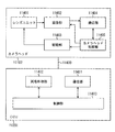
- FIG. 8 shows, for example, the entire configuration of a solid-state imaging device 1 using the photoelectric conversion element 10 described in the above-described embodiment for each pixel.
- the solid-state imaging device 1 is a CMOS image sensor, and has a pixel portion 1a as an imaging area on a semiconductor substrate 11, and a row scanning portion 131, a horizontal selection portion 133, and the like in a peripheral region of the pixel portion 1a.
- a peripheral circuit unit 130 including a column scanning unit 134 and a system control unit 132.
- the pixel unit 1a includes, for example, a plurality of unit pixels P (for example, corresponding to the photoelectric conversion element 10) two-dimensionally arranged in a matrix.
- this unit pixel P for example, pixel drive lines Lread (specifically, row selection lines and reset control lines) are wired for each pixel row, and vertical signal lines Lsig are wired for each pixel column.
- the pixel drive line Lread transmits a drive signal for reading out a signal from the pixel.
- One end of the pixel drive line Lread is connected to an output end corresponding to each row of the row scanning unit 131.
- the row scanning unit 131 is a pixel driving unit that is configured of a shift register, an address decoder, and the like, and drives each unit pixel P of the pixel unit 1a, for example, in units of rows.
- a signal output from each unit pixel P of the pixel row selectively scanned by the row scanning unit 131 is supplied to the horizontal selection unit 133 through each of the vertical signal lines Lsig.
- the horizontal selection unit 133 is configured of an amplifier, a horizontal selection switch, and the like provided for each vertical signal line Lsig.
- the column scanning unit 134 is configured of a shift register, an address decoder, and the like, and drives the horizontal selection switches of the horizontal selection unit 133 in order while scanning them.
- the signal of each pixel transmitted through each vertical signal line Lsig is sequentially output to the horizontal signal line 135 by the selective scanning by the column scanning unit 134, and transmitted to the outside of the semiconductor substrate 11 through the horizontal signal line 135. .
- the circuit portion including the row scanning unit 131, the horizontal selection unit 133, the column scanning unit 134, and the horizontal signal line 135 may be formed directly on the semiconductor substrate 11, or disposed in an external control IC. It may be In addition, those circuit portions may be formed on another substrate connected by a cable or the like.
- the system control unit 132 receives a clock supplied from the outside of the semiconductor substrate 11, data instructing an operation mode, and the like, and outputs data such as internal information of the solid-state imaging device 1.
- the system control unit 132 further includes a timing generator that generates various timing signals, and the row scanning unit 131, the horizontal selection unit 133, the column scanning unit 134, and the like are generated based on the various timing signals generated by the timing generator. Drive control of peripheral circuits.
- the solid-state imaging device 1 described above may be applied to any type of electronic apparatus (solid-state imaging device) having an imaging function such as a camera system such as a digital still camera or a video camera, a mobile phone having an imaging function, it can.
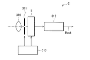
- FIG. 9 shows a schematic configuration of the camera 2 as an example.
- the camera 2 is, for example, a video camera capable of capturing a still image or a moving image, and drives the solid-state imaging device 1, an optical system (optical lens) 310, a shutter device 311, the solid-state imaging device 1 and the shutter device 311 And a signal processing unit 312.
- the optical system 310 guides image light (incident light) from a subject to the pixel unit 1 a of the solid-state imaging device 1.
- the optical system 310 may be composed of a plurality of optical lenses.
- the shutter device 311 controls a light irradiation period and a light shielding period to the solid-state imaging device 1.
- the drive unit 313 controls the transfer operation of the solid-state imaging device 1 and the shutter operation of the shutter device 311.
- the signal processing unit 312 performs various signal processing on the signal output from the solid-state imaging device 1.
- the video signal Dout after signal processing is stored in a storage medium such as a memory or output to a monitor or the like.
- Application Example 3 Example of application to internal information acquisition system> Furthermore, the technology according to the present disclosure (the present technology) can be applied to various products. For example, the technology according to the present disclosure may be applied to an endoscopic surgery system.
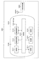
- FIG. 10 is a block diagram showing an example of a schematic configuration of a patient's in-vivo information acquiring system using a capsule endoscope to which the technology (the present technology) according to the present disclosure can be applied.
- the in-vivo information acquisition system 10001 includes a capsule endoscope 10100 and an external control device 10200.
- the capsule endoscope 10100 is swallowed by the patient at the time of examination.
- the capsule endoscope 10100 has an imaging function and a wireless communication function, and moves inside the organ such as the stomach and intestine by peristaltic movement and the like while being naturally discharged from the patient, Images (hereinafter, also referred to as in-vivo images) are sequentially captured at predetermined intervals, and information on the in-vivo images is sequentially wirelessly transmitted to the external control device 10200 outside the body.
- the external control device 10200 centrally controls the operation of the in-vivo information acquisition system 10001. Further, the external control device 10200 receives the information on the in-vivo image transmitted from the capsule endoscope 10100, and based on the information on the received in-vivo image, the in-vivo image is displayed on the display device (not shown). Generate image data to display the
- the in-vivo information acquisition system 10001 can obtain an in-vivo image obtained by imaging the appearance of the inside of the patient's body at any time during the period from when the capsule endoscope 10100 is swallowed until it is discharged.
- the capsule endoscope 10100 has a capsule type casing 10101, and in the casing 10101, a light source unit 10111, an imaging unit 10112, an image processing unit 10113, a wireless communication unit 10114, a power feeding unit 10115, a power supply unit 10116 and a control unit 10117 are accommodated.
- the light source unit 10111 includes, for example, a light source such as an LED (light emitting diode), and emits light to the imaging field of the imaging unit 10112.
- a light source such as an LED (light emitting diode)
- the imaging unit 10112 includes an imaging device and an optical system including a plurality of lenses provided in front of the imaging device. Reflected light of light irradiated to the body tissue to be observed (hereinafter referred to as observation light) is collected by the optical system and is incident on the imaging device. In the imaging unit 10112, in the imaging device, observation light incident thereon is photoelectrically converted, and an image signal corresponding to the observation light is generated. The image signal generated by the imaging unit 10112 is provided to the image processing unit 10113.
- the image processing unit 10113 is configured by a processor such as a central processing unit (CPU) or a graphics processing unit (GPU), and performs various signal processing on the image signal generated by the imaging unit 10112.
- the image processing unit 10113 supplies the image signal subjected to the signal processing to the wireless communication unit 10114 as RAW data.
- the wireless communication unit 10114 performs predetermined processing such as modulation processing on the image signal subjected to the signal processing by the image processing unit 10113, and transmits the image signal to the external control device 10200 via the antenna 10114A. Also, the wireless communication unit 10114 receives a control signal related to drive control of the capsule endoscope 10100 from the external control device 10200 via the antenna 10114A. The wireless communication unit 10114 supplies the control signal received from the external control device 10200 to the control unit 10117.
- the feeding unit 10115 includes an antenna coil for receiving power, a power regeneration circuit that regenerates power from the current generated in the antenna coil, a booster circuit, and the like.
- the power supply unit 10115 generates power using the principle of so-called contactless charging.
- the power supply unit 10116 is formed of a secondary battery, and stores the power generated by the power supply unit 10115. Although an arrow or the like indicating the supply destination of the power from the power supply unit 10116 is omitted in FIG. 10 in order to avoid complication of the drawing, the power stored in the power supply unit 10116 is the light source unit 10111. , The image processing unit 10113, the wireless communication unit 10114, and the control unit 10117, and may be used to drive them.
- the control unit 10117 includes a processor such as a CPU, and is a control signal transmitted from the external control device 10200 to drive the light source unit 10111, the imaging unit 10112, the image processing unit 10113, the wireless communication unit 10114, and the power feeding unit 10115. Control as appropriate.
- the external control device 10200 is configured of a processor such as a CPU or a GPU, or a microcomputer or control board or the like in which memory elements such as a processor and a memory are mixed.
- the external control device 10200 controls the operation of the capsule endoscope 10100 by transmitting a control signal to the control unit 10117 of the capsule endoscope 10100 via the antenna 10200A.
- the control condition from the external control device 10200 may change the irradiation condition of light to the observation target in the light source unit 10111.
- an imaging condition for example, a frame rate in the imaging unit 10112, an exposure value, etc.
- the contents of processing in the image processing unit 10113 and conditions (for example, transmission interval, number of transmission images, etc.) under which the wireless communication unit 10114 transmits an image signal may be changed by a control signal from the external control device 10200. .
- the external control device 10200 performs various types of image processing on the image signal transmitted from the capsule endoscope 10100, and generates image data for displaying the captured in-vivo image on the display device.
- image processing for example, development processing (demosaicing processing), high image quality processing (band emphasis processing, super-resolution processing, NR (noise reduction) processing and / or camera shake correction processing, etc.), and / or enlargement processing ( Various signal processing such as electronic zoom processing can be performed.
- the external control device 10200 controls driving of the display device to display the in-vivo image captured based on the generated image data.
- the external control device 10200 may cause the generated image data to be recorded on a recording device (not shown) or cause the printing device (not shown) to print out.
- the technique according to the present disclosure may be applied to, for example, the imaging unit 10112 among the configurations described above. This improves the detection accuracy.
- Application Example 4 Application example to endoscopic surgery system>
- the technology according to the present disclosure (the present technology) can be applied to various products.
- the technology according to the present disclosure may be applied to an endoscopic surgery system.
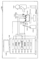
- FIG. 11 is a diagram showing an example of a schematic configuration of an endoscopic surgery system to which the technology (the present technology) according to the present disclosure can be applied.
- FIG. 11 illustrates a surgeon (doctor) 11131 performing surgery on a patient 11132 on a patient bed 11133 using the endoscopic surgery system 11000.
- the endoscopic surgery system 11000 includes an endoscope 11100, other surgical instruments 11110 such as an insufflation tube 11111 and an energy treatment instrument 11112, and a support arm device 11120 for supporting the endoscope 11100.
- a cart 11200 on which various devices for endoscopic surgery are mounted.
- the endoscope 11100 includes a lens barrel 11101 whose region of a predetermined length from the tip is inserted into a body cavity of a patient 11132, and a camera head 11102 connected to a proximal end of the lens barrel 11101.
- the endoscope 11100 configured as a so-called rigid endoscope having a rigid barrel 11101 is illustrated, but even if the endoscope 11100 is configured as a so-called flexible mirror having a flexible barrel Good.
- the endoscope 11100 may be a straight endoscope, or may be a oblique endoscope or a side endoscope.
- An optical system and an imaging device are provided inside the camera head 11102, and the reflected light (observation light) from the observation target is condensed on the imaging device by the optical system.
- the observation light is photoelectrically converted by the imaging element to generate an electric signal corresponding to the observation light, that is, an image signal corresponding to the observation image.
- the image signal is transmitted as RAW data to a camera control unit (CCU: Camera Control Unit) 11201.
- CCU Camera Control Unit
- the CCU 11201 is configured by a CPU (Central Processing Unit), a GPU (Graphics Processing Unit), and the like, and centrally controls the operations of the endoscope 11100 and the display device 11202. Furthermore, the CCU 11201 receives an image signal from the camera head 11102 and performs various image processing for displaying an image based on the image signal, such as development processing (demosaicing processing), on the image signal.
- a CPU Central Processing Unit
- GPU Graphics Processing Unit
- the display device 11202 displays an image based on an image signal subjected to image processing by the CCU 11201 under control of the CCU 11201.
- the light source device 11203 includes, for example, a light source such as an LED (light emitting diode), and supplies the endoscope 11100 with irradiation light at the time of imaging an operation part or the like.
- a light source such as an LED (light emitting diode)
- the input device 11204 is an input interface to the endoscopic surgery system 11000.
- the user can input various information and input instructions to the endoscopic surgery system 11000 via the input device 11204.
- the user inputs an instruction to change the imaging condition (type of irradiated light, magnification, focal length, and the like) by the endoscope 11100, and the like.
- the treatment tool control device 11205 controls the drive of the energy treatment tool 11112 for ablation of tissue, incision, sealing of a blood vessel, and the like.
- the insufflation apparatus 11206 is a gas within the body cavity via the insufflation tube 11111 in order to expand the body cavity of the patient 11132 for the purpose of securing a visual field by the endoscope 11100 and securing a working space of the operator.
- Send The recorder 11207 is a device capable of recording various types of information regarding surgery.
- the printer 11208 is an apparatus capable of printing various types of information regarding surgery in various types such as text, images, and graphs.
- the light source device 11203 that supplies the irradiation light when imaging the surgical site to the endoscope 11100 can be configured of, for example, an LED, a laser light source, or a white light source configured by a combination of these.
- a white light source is configured by a combination of RGB laser light sources
- the output intensity and output timing of each color (each wavelength) can be controlled with high precision. It can be carried out.
- the laser light from each of the RGB laser light sources is irradiated to the observation target in time division, and the drive of the image pickup element of the camera head 11102 is controlled in synchronization with the irradiation timing to cope with each of RGB. It is also possible to capture a shot image in time division. According to the method, a color image can be obtained without providing a color filter in the imaging device.
- the drive of the light source device 11203 may be controlled so as to change the intensity of the light to be output every predetermined time.
- the drive of the imaging device of the camera head 11102 is controlled in synchronization with the timing of the change of the light intensity to acquire images in time division, and by combining the images, high dynamic without so-called blackout and whiteout is obtained. An image of the range can be generated.
- the light source device 11203 may be configured to be able to supply light of a predetermined wavelength band corresponding to special light observation.
- special light observation for example, the mucous membrane surface layer is irradiated by irradiating narrow band light as compared with irradiation light (that is, white light) at the time of normal observation using the wavelength dependency of light absorption in body tissue.
- the so-called narrow band imaging is performed to image a predetermined tissue such as a blood vessel with high contrast.
- fluorescence observation may be performed in which an image is obtained by fluorescence generated by irradiation with excitation light.
- body tissue is irradiated with excitation light and fluorescence from the body tissue is observed (autofluorescence observation), or a reagent such as indocyanine green (ICG) is locally injected into body tissue and the body tissue is Excitation light corresponding to the fluorescence wavelength of the reagent can be irradiated to obtain a fluorescence image or the like.
- the light source device 11203 can be configured to be able to supply narrow band light and / or excitation light corresponding to such special light observation.
- FIG. 12 is a block diagram showing an example of the functional configuration of the camera head 11102 and the CCU 11201 shown in FIG.
- the camera head 11102 includes a lens unit 11401, an imaging unit 11402, a drive unit 11403, a communication unit 11404, and a camera head control unit 11405.
- the CCU 11201 includes a communication unit 11411, an image processing unit 11412, and a control unit 11413.
- the camera head 11102 and the CCU 11201 are communicably connected to each other by a transmission cable 11400.
- the lens unit 11401 is an optical system provided at a connection portion with the lens barrel 11101.
- the observation light taken in from the tip of the lens barrel 11101 is guided to the camera head 11102 and is incident on the lens unit 11401.
- the lens unit 11401 is configured by combining a plurality of lenses including a zoom lens and a focus lens.
- the imaging device constituting the imaging unit 11402 may be one (a so-called single-plate type) or a plurality (a so-called multi-plate type).
- the imaging unit 11402 When the imaging unit 11402 is configured as a multi-plate type, for example, an image signal corresponding to each of RGB may be generated by each imaging element, and a color image may be obtained by combining them.
- the imaging unit 11402 may be configured to have a pair of imaging devices for acquiring image signals for right eye and left eye corresponding to 3D (dimensional) display. By performing 3D display, the operator 11131 can more accurately grasp the depth of the living tissue in the operation site.
- a plurality of lens units 11401 may be provided corresponding to each imaging element.
- the imaging unit 11402 may not necessarily be provided in the camera head 11102.
- the imaging unit 11402 may be provided inside the lens barrel 11101 immediately after the objective lens.
- the driving unit 11403 is configured by an actuator, and moves the zoom lens and the focusing lens of the lens unit 11401 by a predetermined distance along the optical axis under the control of the camera head control unit 11405. Thereby, the magnification and the focus of the captured image by the imaging unit 11402 can be appropriately adjusted.
- the communication unit 11404 is configured of a communication device for transmitting and receiving various types of information to and from the CCU 11201.
- the communication unit 11404 transmits the image signal obtained from the imaging unit 11402 to the CCU 11201 as RAW data via the transmission cable 11400.
- the communication unit 11404 also receives a control signal for controlling the drive of the camera head 11102 from the CCU 11201 and supplies the control signal to the camera head control unit 11405.
- the control signal includes, for example, information indicating that the frame rate of the captured image is designated, information indicating that the exposure value at the time of imaging is designated, and / or information indicating that the magnification and focus of the captured image are designated, etc. Contains information about the condition.
- the imaging conditions such as the frame rate, exposure value, magnification, and focus described above may be appropriately designated by the user, or may be automatically set by the control unit 11413 of the CCU 11201 based on the acquired image signal. Good. In the latter case, the so-called AE (Auto Exposure) function, AF (Auto Focus) function, and AWB (Auto White Balance) function are incorporated in the endoscope 11100.
- AE Auto Exposure
- AF Auto Focus
- AWB Automatic White Balance
- the camera head control unit 11405 controls the drive of the camera head 11102 based on the control signal from the CCU 11201 received via the communication unit 11404.
- the communication unit 11411 is configured by a communication device for transmitting and receiving various types of information to and from the camera head 11102.
- the communication unit 11411 receives an image signal transmitted from the camera head 11102 via the transmission cable 11400.
- the communication unit 11411 transmits a control signal for controlling driving of the camera head 11102 to the camera head 11102.
- the image signal and the control signal can be transmitted by telecommunication or optical communication.
- An image processing unit 11412 performs various types of image processing on an image signal that is RAW data transmitted from the camera head 11102.
- the control unit 11413 performs various types of control regarding imaging of a surgical site and the like by the endoscope 11100 and display of a captured image obtained by imaging of the surgical site and the like. For example, the control unit 11413 generates a control signal for controlling the drive of the camera head 11102.
- control unit 11413 causes the display device 11202 to display a captured image in which a surgical site or the like is captured, based on the image signal subjected to the image processing by the image processing unit 11412.
- the control unit 11413 may recognize various objects in the captured image using various image recognition techniques. For example, the control unit 11413 detects a shape, a color, and the like of an edge of an object included in a captured image, thereby enabling a surgical tool such as forceps, a specific biological site, bleeding, mist when using the energy treatment tool 11112, and the like. It can be recognized.
- control unit 11413 may superimpose various surgical support information on the image of the surgery section using the recognition result.
- the operation support information is superimposed and presented to the operator 11131, whereby the burden on the operator 11131 can be reduced and the operator 11131 can reliably proceed with the operation.
- a transmission cable 11400 connecting the camera head 11102 and the CCU 11201 is an electric signal cable corresponding to communication of an electric signal, an optical fiber corresponding to optical communication, or a composite cable of these.
- communication is performed by wire communication using the transmission cable 11400, but communication between the camera head 11102 and the CCU 11201 may be performed wirelessly.
- the technology according to the present disclosure may be applied to the imaging unit 11402 among the configurations described above.
- the detection accuracy is improved by applying the technology according to the present disclosure to the imaging unit 11402.
- the technology according to the present disclosure can be applied to various products.
- the technology according to the present disclosure is any type of movement, such as automobiles, electric vehicles, hybrid electric vehicles, motorcycles, bicycles, personal mobility, airplanes, drones, ships, robots, construction machines, agricultural machines (tractors), etc. It may be realized as a device mounted on the body.
- FIG. 13 is a block diagram showing a schematic configuration example of a vehicle control system that is an example of a mobile control system to which the technology according to the present disclosure can be applied.
- Vehicle control system 12000 includes a plurality of electronic control units connected via communication network 12001.
- the vehicle control system 12000 includes a drive system control unit 12010, a body system control unit 12020, an external information detection unit 12030, an in-vehicle information detection unit 12040, and an integrated control unit 12050.
- a microcomputer 12051, an audio image output unit 12052, and an in-vehicle network I / F (interface) 12053 are illustrated as a functional configuration of the integrated control unit 12050.
- the driveline control unit 12010 controls the operation of devices related to the driveline of the vehicle according to various programs.
- the drive system control unit 12010 includes a drive force generation device for generating a drive force of a vehicle such as an internal combustion engine or a drive motor, a drive force transmission mechanism for transmitting the drive force to the wheels, and a steering angle of the vehicle. It functions as a control mechanism such as a steering mechanism that adjusts and a braking device that generates a braking force of the vehicle.
- Body system control unit 12020 controls the operation of various devices equipped on the vehicle body according to various programs.
- the body system control unit 12020 functions as a keyless entry system, a smart key system, a power window device, or a control device of various lamps such as a headlamp, a back lamp, a brake lamp, a blinker or a fog lamp.
- the body system control unit 12020 may receive radio waves or signals of various switches transmitted from a portable device substituting a key.
- Body system control unit 12020 receives the input of these radio waves or signals, and controls a door lock device, a power window device, a lamp and the like of the vehicle.
- Outside vehicle information detection unit 12030 detects information outside the vehicle equipped with vehicle control system 12000.
- an imaging unit 12031 is connected to the external information detection unit 12030.
- the out-of-vehicle information detection unit 12030 causes the imaging unit 12031 to capture an image outside the vehicle, and receives the captured image.
- the external information detection unit 12030 may perform object detection processing or distance detection processing of a person, a vehicle, an obstacle, a sign, characters on a road surface, or the like based on the received image.
- the imaging unit 12031 is an optical sensor that receives light and outputs an electrical signal according to the amount of light received.
- the imaging unit 12031 can output an electric signal as an image or can output it as distance measurement information.
- the light received by the imaging unit 12031 may be visible light or non-visible light such as infrared light.
- In-vehicle information detection unit 12040 detects in-vehicle information.
- a driver state detection unit 12041 that detects a state of a driver is connected to the in-vehicle information detection unit 12040.
- the driver state detection unit 12041 includes, for example, a camera for imaging the driver, and the in-vehicle information detection unit 12040 determines the degree of fatigue or concentration of the driver based on the detection information input from the driver state detection unit 12041. It may be calculated or it may be determined whether the driver does not go to sleep.
- the microcomputer 12051 calculates a control target value of the driving force generation device, the steering mechanism or the braking device based on the information inside and outside the vehicle acquired by the outside information detecting unit 12030 or the in-vehicle information detecting unit 12040, and a drive system control unit A control command can be output to 12010.
- the microcomputer 12051 controls the driving force generating device, the steering mechanism, the braking device, and the like based on the information around the vehicle acquired by the outside information detecting unit 12030 or the in-vehicle information detecting unit 12040 so that the driver can Coordinated control can be performed for the purpose of automatic driving that travels autonomously without depending on the operation.
- the microcomputer 12051 can output a control command to the body system control unit 12020 based on the information outside the vehicle acquired by the external information detection unit 12030.
- the microcomputer 12051 controls the headlamp according to the position of the preceding vehicle or oncoming vehicle detected by the external information detection unit 12030, and performs cooperative control for the purpose of antiglare such as switching the high beam to the low beam. It can be carried out.
- the audio image output unit 12052 transmits an output signal of at least one of audio and image to an output device capable of visually or aurally notifying information to a passenger or the outside of a vehicle.
- an audio speaker 12061, a display unit 12062, and an instrument panel 12063 are illustrated as the output device.
- the display unit 12062 may include, for example, at least one of an on-board display and a head-up display.
- FIG. 14 is a diagram illustrating an example of the installation position of the imaging unit 12031.
- imaging units 12101, 12102, 12103, 12104, and 12105 are provided as the imaging unit 12031.
- the imaging units 12101, 12102, 12103, 12104, and 12105 are provided, for example, at positions such as the front nose of the vehicle 12100, a side mirror, a rear bumper, a back door, and an upper portion of a windshield of a vehicle interior.
- the imaging unit 12101 provided in the front nose and the imaging unit 12105 provided in the upper part of the windshield in the vehicle cabin mainly acquire an image in front of the vehicle 12100.
- the imaging units 12102 and 12103 included in the side mirror mainly acquire an image of the side of the vehicle 12100.
- the imaging unit 12104 provided in the rear bumper or the back door mainly acquires an image of the rear of the vehicle 12100.
- the imaging unit 12105 provided on the top of the windshield in the passenger compartment is mainly used to detect a leading vehicle or a pedestrian, an obstacle, a traffic light, a traffic sign, a lane, or the like.
- FIG. 14 shows an example of the imaging range of the imaging units 12101 to 12104.
- the imaging range 12111 indicates the imaging range of the imaging unit 12101 provided on the front nose
- the imaging ranges 12112 and 12113 indicate the imaging ranges of the imaging units 12102 and 12103 provided on the side mirrors
- the imaging range 12114 indicates The imaging range of the imaging part 12104 provided in the rear bumper or the back door is shown. For example, by overlaying the image data captured by the imaging units 12101 to 12104, a bird's eye view of the vehicle 12100 viewed from above can be obtained.
- At least one of the imaging units 12101 to 12104 may have a function of acquiring distance information.
- at least one of the imaging units 12101 to 12104 may be a stereo camera including a plurality of imaging devices, or an imaging device having pixels for phase difference detection.
- the microcomputer 12051 measures the distance to each three-dimensional object in the imaging ranges 12111 to 12114, and the temporal change of this distance (relative velocity with respect to the vehicle 12100). In particular, it is possible to extract a three-dimensional object traveling at a predetermined speed (for example, 0 km / h or more) in substantially the same direction as the vehicle 12100 as a leading vehicle, in particular by finding the it can. Further, the microcomputer 12051 can set an inter-vehicle distance to be secured in advance before the preceding vehicle, and can perform automatic brake control (including follow-up stop control), automatic acceleration control (including follow-up start control), and the like. As described above, it is possible to perform coordinated control for the purpose of automatic driving or the like that travels autonomously without depending on the driver's operation.
- automatic brake control including follow-up stop control
- automatic acceleration control including follow-up start control
- the microcomputer 12051 converts three-dimensional object data relating to three-dimensional objects into two-dimensional vehicles such as two-wheeled vehicles, ordinary vehicles, large vehicles, pedestrians, telephone poles, and other three-dimensional objects. It can be classified, extracted and used for automatic avoidance of obstacles. For example, the microcomputer 12051 identifies obstacles around the vehicle 12100 into obstacles visible to the driver of the vehicle 12100 and obstacles difficult to see.
- the microcomputer 12051 determines the collision risk indicating the degree of risk of collision with each obstacle, and when the collision risk is a setting value or more and there is a possibility of a collision, through the audio speaker 12061 or the display unit 12062 By outputting an alarm to the driver or performing forcible deceleration or avoidance steering via the drive system control unit 12010, driving support for collision avoidance can be performed.
- At least one of the imaging units 12101 to 12104 may be an infrared camera that detects infrared light.
- the microcomputer 12051 can recognize a pedestrian by determining whether a pedestrian is present in the images captured by the imaging units 12101 to 12104.
- pedestrian recognition is, for example, a procedure for extracting feature points in images captured by the imaging units 12101 to 12104 as an infrared camera, and pattern matching processing on a series of feature points indicating the outline of an object to determine whether it is a pedestrian or not
- the procedure is to determine
- the audio image output unit 12052 generates a square outline for highlighting the recognized pedestrian.
- the display unit 12062 is controlled so as to display a superimposed image. Further, the audio image output unit 12052 may control the display unit 12062 to display an icon or the like indicating a pedestrian at a desired position.
- the substrate temperature is 40 by resistance heating while rotating the substrate holder under a vacuum of 1 ⁇ 10 -5 Pa or less.
- An organic photoelectric conversion layer was formed at ° C.
- the material of the organic photoelectric conversion layer is 3,6BP-BBTN shown in the following formula (1) as a hole transporting material (P material), and a subphthalocyanine derivative (F 6 -SubPc-OPh 26 F 2 as a light absorber And fullerene C60 as an electron transporting material (N material), and these were co-deposited.
- B4PyPMP was formed as a buffer layer on the photoelectric conversion layer at a substrate temperature of 0 ° C. to a thickness of 5 nm by vacuum evaporation.
- ITO was formed into a film to a thickness of 100 nm by sputtering as the upper electrode 17, and heat treatment was performed at 160 ° C.
- the photoelectric conversion element (Experimental example 1) which has a photoelectric conversion area
- photoelectric conversion elements to be experimental examples 2 to 8 were produced.
- Photoelectric conversion is performed using the same method as Experimental Example 1 except that the substrate temperature during film formation of the organic photoelectric conversion layer is 25 ° C. (Experimental Example 2) and 0 ° C. (Experimental Example 3).
- a device was produced.
- a photoelectric conversion element was manufactured using the same method as Experimental Example 3 except that the heat treatment after forming the organic film (after forming the buffer layer) was omitted (As depo).
- Experimental Example 5 a photoelectric conversion element was produced using the same method as in Experimental Example 3 except that BP-ChDT (Formula (2)) was used as the P material.
- DBPA (formula (3)) is used as the P material, and the substrate temperature at the time of forming the organic photoelectric conversion layer and the heat treatment condition after forming the organic film are respectively -10.
- Photoelectric conversion elements were manufactured as ° C., ANL 160 ° C. (Experimental Example 6), ⁇ 10 ° C., As depo (Experimental Example 7), 40 ° C., ANL 160 ° C. (Experimental Example 8).
- the responsiveness (post-image characteristics) of Experimental Examples 1 to 8 was evaluated. Evaluation of the afterimage characteristics was performed by measuring the speed at which the light current value observed at the time of light irradiation falls after stopping the light irradiation using a semiconductor parameter analyzer. Specifically, the amount of light emitted from the light source to the photoelectric conversion element through the filter is 1.62 ⁇ W / cm 2, and the bias voltage applied between the electrodes is ⁇ 2.6 V. After observing the steady state current in this state, we stopped light irradiation and observed how the current decayed. Subsequently, the area surrounded by the current-time curve and the dark current was 100%, and the time until this area corresponded to 3% was used as an indicator of responsiveness. All these evaluations were performed at room temperature.
- the quantum efficiencies (external quantum efficiencies; EQE) of Experimental Examples 1 to 8 were evaluated using a semiconductor parameter analyzer. Specifically, the light amount of light (LED light with a wavelength of 560 nm) emitted from the light source to the photoelectric conversion element through the filter is 1.62 ⁇ W / cm 2, and the bias voltage applied between the electrodes is -2.6 V The external photoelectric conversion efficiency was calculated from the light current value and the dark current value in the case of
- a thin film sample is produced from the region of the organic photoelectric conversion layer of the sample of the above-mentioned Experimental example 1 using a focused ion beam (Focused Ion Beam; FIB, HELIOS NANOLAB 400S manufactured by FEI), and then an ion milling apparatus (Fischione Model 1040) ) Removed the damaged layer on the end of FIB processing.
- a focused ion beam Fluorine Model 1040
- the defocusing condition for observing the domain was performed in a state in which the transmission image was in focus, that is, in a state shifted about 1500 nm from the just focus position to the under side.
- transmission microscope analysis of the above-mentioned Experimental Examples 2 to 8 was conducted using the same method.
- FIG. 15 shows a TEM image (A) obtained by enlarging the interference fringe portion of Experimental Example 1 and a signal intensity of the TEM image measured with a TEM image software (Digital Micrograph) (B).
- the interference fringes of the TEM image appear as peaks or valleys of the signal intensity depending on the strength of the contrast.
- the pair of adjacent lines forming the interference fringes represent the molecular period in the major axis direction of the P material.
- the molecular length of the P material used in Experimental Example 1 is about 3 nm, while the distance between a pair of lines forming the interference fringe in FIG. 15B is 2.2 nm. From this, it can be said that the interference fringes are interference fringes having a period in the major axis direction of the P material.
- FIG. 16 shows TEM images of Experimental Example 1 (A) and Experimental Example 4 (B).
- FIG. 17 shows TEM images of Experimental Example 6 (A) and Experimental Example 8 (B).
- Table 1 summarizes the film formation conditions of the P materials and the organic photoelectric conversion layers used in Experimental Examples 1 to 8 and the respective electrical characteristics and the results of transmission type microscopic analysis.
- Experimental Examples 1 and 4 in which 3,6 BP-BBTN was used as the P material, interference fringes indicating domains extending in the film thickness direction were observed in Experimental Example 1 in which heat treatment was performed at 160 ° C. after forming the organic film.
- no interference fringes could be observed in Experimental Example 4 in which the heat treatment was not performed after the formation of the organic film (As depo).
- the angle between the interference fringes and the electrode surface of the lower electrode 15 is preferably larger than 45 ° and 90 ° or smaller, but this is because of the following reasons.
- this domain is a charge transport path.
- the domain constituted by the P material contributes to the hole transport efficiency, thereby improving the response speed to obtain good afterimage characteristics.
- a relatively good residual image characteristic was obtained even when the angle between the interference fringes and the electrode surface was 49.7 ° (Experimental Example 3).
- the angle between the interference fringes and the electrode surface be greater than 45 ° and 90 ° or less in the extending direction of the interference fringes. More preferably, it is 63 ° or more and 90 ° or less, and more preferably 82 ° or more and 90 ° or less.
- the distance between two adjacent lines forming the interference fringes is preferably within ⁇ 50% with respect to the molecular length of the p-type semiconductor. It is from a reason. While the molecular length in the long axis direction of 3,6BP-BBTN used in Experimental Example 1 was about 3 nm, the distance between interference fringes was 2.2 nm, and the difference was about 27%. A major cause of this difference is that the long molecular axis is not perpendicular but inclined with respect to the direction in which the interference fringes extend or the direction of electron transmission. When the molecular long axis is inclined with respect to the electrode surface, the distance between the pair of lines forming the interference fringes is shorter than the molecular length.
- the following variation factors due to the amount of focus of the transmission electron microscope can be considered.
- As a first factor in the image of the transmission electron microscope, how the image is blurred differs depending on the defocus amount, and the distance between the pair of lines constituting the interference fringes becomes long due to the defocus amount becoming large.
- the defocus amount fluctuates due to an error in the position of defocus zero.
- the standard of the defocus amount zero is determined from the position where the contrast is weakest by visually checking the contrast of the sample end while changing the sample height.
- the amount of focus varies depending on the position of the p-type semiconductor in the sample, and this also changes the distance between the pair of lines. From the above, it can be said that the distance between two adjacent lines forming the interference fringes is preferably within ⁇ 50% with respect to the molecular length of the p-type semiconductor.
- an embodiment, modification, and an example were mentioned and explained, the present disclosure content is not limited to the above-mentioned embodiment etc., and can be variously modified.
- an organic photoelectric conversion unit 11G that detects green light and an inorganic photoelectric conversion unit 11B and an inorganic photoelectric conversion unit 11R that detects blue light and red light are stacked.
- the present disclosure is not limited to such a structure. That is, red light or blue light may be detected in the organic photoelectric conversion unit, and green light may be detected in the inorganic photoelectric conversion unit.
- the number and ratio of the organic photoelectric conversion unit and the inorganic photoelectric conversion unit are not limited, and two or more organic photoelectric conversion units may be provided, or colors of plural colors may be provided by the organic photoelectric conversion unit alone. A signal may be obtained.
- the structure is not limited to the structure in which the organic photoelectric conversion unit and the inorganic photoelectric conversion unit are vertically stacked, and may be parallel along the substrate surface.
- the configuration of the backside illumination type solid-state imaging device is illustrated, but the present disclosure can also be applied to the front side illumination type solid-state imaging device.
- the photoelectric conversion element of the present disclosure it is not necessary to include all the components described in the above embodiment, and conversely, other layers may be provided.
- the present disclosure may have the following configuration. (1) A first electrode, A second electrode disposed opposite to the first electrode; And an organic photoelectric conversion layer provided between the first electrode and the second electrode and having a domain of one organic semiconductor material in the layer.
- the domain of the one organic semiconductor material has a percolation structure longitudinally cutting the organic photoelectric conversion layer in the film thickness direction, and the domain length of the organic photoelectric conversion layer in the planar direction is the film thickness direction of the organic photoelectric conversion layer A photoelectric conversion element smaller than the domain length.
- the organic photoelectric conversion layer has an interference fringe constituted by two or more lines in a cross-sectional photograph in the film thickness direction taken under a defocus condition by a transmission electron microscope,
- the photoelectric conversion element according to (1) wherein an interval between two or more lines forming the interference fringes is within ⁇ 50% with respect to a molecular length of the one organic semiconductor material.
- an angle between the interference fringes and the electrode surface of the first electrode is greater than 45 ° and not more than 90 °.
- Each pixel includes one or more organic photoelectric conversion units, The organic photoelectric conversion unit is A first electrode, A second electrode disposed opposite to the first electrode; And an organic photoelectric conversion layer provided between the first electrode and the second electrode and having a domain of one organic semiconductor material in the layer.
- the domain of the one organic semiconductor material has a percolation structure longitudinally cutting the organic photoelectric conversion layer in the film thickness direction, and the domain length of the organic photoelectric conversion layer in the planar direction is the film thickness direction of the organic photoelectric conversion layer Solid-state imager smaller than domain length.
- the organic photoelectric conversion units and one or more inorganic photoelectric conversion units that perform photoelectric conversion in a wavelength range different from that of the organic photoelectric conversion unit are stacked.
- Solid-state imaging device as described.
- the inorganic photoelectric conversion unit is embedded in a semiconductor substrate, The solid-state imaging device according to (9), wherein the organic photoelectric conversion unit is formed on the first surface side of the semiconductor substrate.
- the solid-state imaging device according to (10), wherein a multilayer wiring layer is formed on the second surface side of the semiconductor substrate.
- the organic photoelectric conversion unit performs photoelectric conversion of green light
- the solid-state imaging according to (10) or (11) wherein an inorganic photoelectric conversion unit performing photoelectric conversion of blue light and an inorganic photoelectric conversion unit performing photoelectric conversion of red light are stacked in the semiconductor substrate. apparatus.
- (13) The solid-state imaging device according to any one of (8) to (12), wherein in each pixel, a plurality of the organic photoelectric conversion units that perform photoelectric conversion in different wavelength ranges are stacked.
Landscapes
- Physics & Mathematics (AREA)
- Electromagnetism (AREA)
- Chemical & Material Sciences (AREA)
- Engineering & Computer Science (AREA)
- Materials Engineering (AREA)
- Spectroscopy & Molecular Physics (AREA)
- Inorganic Chemistry (AREA)
- Nanotechnology (AREA)
- Solid State Image Pick-Up Elements (AREA)
- Light Receiving Elements (AREA)
Abstract
Description
1.実施の形態(所定の形状のドメインを形成する一の有機半導体材料を用いて有機光電変換層を構成した光電変換素子)
1-1.光電変換素子の構成
1-2.光電変換素子の製造方法
1-3.作用・効果
2.変形例(複数の有機光電変換部が積層された光電変換素子)
3.適用例
4.実施例
図1は、本開示の一実施の形態の光電変換素子(光電変換素子10)の断面構成を表したものである。光電変換素子10は、例えば、裏面照射型(裏面受光型)のCCD(Charge Coupled Device)イメージセンサまたはCMOS(Complementary Metal Oxide Semiconductor)イメージセンサ等の固体撮像装置(固体撮像装置1)において1つの画素(単位画素P)を構成するものである(図8参照)。光電変換素子10は、それぞれ異なる波長域の光を選択的に検出して光電変換を行う1つの有機光電変換部11Gと、2つの無機光電変換部11B,11Rとが縦方向に積層された、いわゆる縦方向分光型のものである。本実施の形態では、有機光電変換部11Gを構成する有機光電変換層16が、層内に所定の形状のドメインを形成する有機半導体材料(一の有機半導体材料)を用いて形成された構成を有する。
光電変換素子10は、単位画素P毎に、1つの有機光電変換部11Gと、2つの無機光電変換部11B,11Rとが縦方向に積層されものである。有機光電変換部11Gは、半導体基板11の裏面(第1面11S1)側に設けられている。無機光電変換部11B,11Rは、半導体基板11内に埋め込み形成されており、半導体基板11の厚み方向に積層されている。有機光電変換部11Gは、p型半導体およびn型半導体を含んで構成され、層内にバルクヘテロ接合構造を有する有機光電変換層16を含む。バルクヘテロ接合構造は、p型半導体およびn型半導体が混ざり合うことで形成されたp/n接合面である。
本実施の形態の光電変換素子10は、例えば、次のようにして製造することができる。
光電変換素子10へ入射した光のうち、まず、緑色光が、有機光電変換部11Gにおいて選択的に検出(吸収)され、光電変換される。
続いて、有機光電変換部11Gを透過した光のうち、青色光は無機光電変換部11B、赤色光は無機光電変換部11Rにおいて、それぞれ順に吸収され、光電変換される。無機光電変換部11Bでは、入射した青色光に対応した電子が無機光電変換部11Bのn領域に蓄積され、蓄積された電子は、縦型トランジスタTr1によりフローティングディフュージョンFD1へと転送される。同様に、無機光電変換部11Rでは、入射した赤色光に対応した電子が無機光電変換部11Rのn領域に蓄積され、蓄積された電子は、転送トランジスタTr2によりフローティングディフュージョンFD2へと転送される。
前述したように、有機薄膜太陽電池や有機撮像素子等に用いられる有機光電変換素子では、p型有機半導体およびn型有機半導体を混合したバルクヘテロ構造が採用されている。しかしながら、有機半導体は伝導特性が低いため、有機光電変換素子では、十分な量子効率が得られず、入射光に対して電気的な出力信号が遅延しやすいという課題がある。
図7は、本開示の変形例に係る光電変換素子(光電変換素子20)の断面構成を表したものである。光電変換素子20は、上記実施の形態等の光電変換素子10と同様に、例えば、裏面照射型のCCDイメージセンサまたはCMOSイメージセンサ等の固体撮像素子(固体撮像装置1)において1つの単位画素Pを構成するものである。本変形例の光電変換素子20は、シリコン基板81上に絶縁層82を介して赤色光電変換部40R、緑色光電変換部40Gおよび青色光電変換部40Bがこの順に積層された構成を有する。
(適用例1)
図8は、例えば、上記実施の形態において説明した光電変換素子10を各画素に用いた固体撮像装置1の全体構成を表したものである。この固体撮像装置1は、CMOSイメージセンサであり、半導体基板11上に、撮像エリアとしての画素部1aを有すると共に、この画素部1aの周辺領域に、例えば、行走査部131、水平選択部133、列走査部134およびシステム制御部132からなる周辺回路部130を有している。
上述の固体撮像装置1は、例えば、デジタルスチルカメラやビデオカメラ等のカメラシステムや、撮像機能を有する携帯電話等、撮像機能を備えたあらゆるタイプの電子機器(固体撮像装置)に適用することができる。図9に、その一例として、カメラ2の概略構成を示す。このカメラ2は、例えば、静止画または動画を撮影可能なビデオカメラであり、固体撮像装置1と、光学系(光学レンズ)310と、シャッタ装置311と、固体撮像装置1およびシャッタ装置311を駆動する駆動部313と、信号処理部312とを有する。
<体内情報取得システムへの応用例>
更に、本開示に係る技術(本技術)は、様々な製品へ応用することができる。例えば、本開示に係る技術は、内視鏡手術システムに適用されてもよい。
<4.内視鏡手術システムへの応用例>
本開示に係る技術(本技術)は、様々な製品へ応用することができる。例えば、本開示に係る技術は、内視鏡手術システムに適用されてもよい。
<移動体への応用例>
本開示に係る技術は、様々な製品へ応用することができる。例えば、本開示に係る技術は、自動車、電気自動車、ハイブリッド電気自動車、自動二輪車、自転車、パーソナルモビリティ、飛行機、ドローン、船舶、ロボット、建設機械、農業機械(トラクター)などのいずれかの種類の移動体に搭載される装置として実現されてもよい。
次に、本開示の実施例について詳細に説明する。
まず、厚さ50nmのITO電極(下部電極)付きSi基板をUV/オゾン処理にて洗浄したのち、1×10-5Pa以下の真空下で基板ホルダを回転させながら抵抗加熱法によって基板温度40℃にて有機光電変換層を成膜した。有機光電変換層の材料としては、正孔輸送性材料(P材料)として下記式(1)に示した3,6BP-BBTN、光吸収体としてサブフタロシアニン誘導体(F6-SubPc-OPh26F2)および電子輸送性材料(N材料)としてフラーレンC60を用い、これらを同時蒸着した。蒸着速度の比率は、3,6BP-BBTN:F6-SubPc-OPh26F2:C60=4:4:2とし、合計膜厚が230nmとなるように成膜した。続いて、光電変換層上にバッファ層としてB4PyPMPを基板温度0℃にて真空蒸着法により5nmの厚みで成膜した。続いて、上部電極17としてITOをスパッタにて厚み100nmとなるように成膜したのち、160℃で加熱処理を行った。以上により、1mm×1mmの光電変換領域を有する光電変換素子(実験例1)を作製した。

また、実験例1~8に対応する有機光電変換層の断面のTEM観察用のサンプルを作製し、有機光電変換層中のP材料ドメインの観察を行った。P材料(正孔輸送性を有する有機半導体材料)のドメインは、透過型電子顕微鏡を用いて透過像を観察することで確認した。
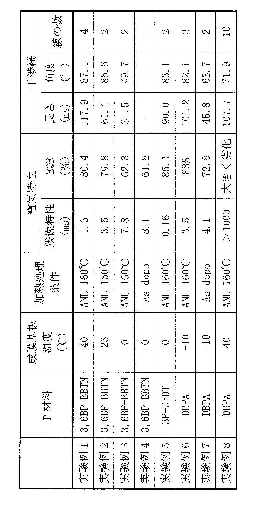
(1)
第1電極と、
前記第1電極に対向配置された第2電極と、
前記第1電極と前記第2電極との間に設けられると共に、層内に一の有機半導体材料のドメインを有する有機光電変換層とを備え、
前記一の有機半導体材料のドメインは、前記有機光電変換層を膜厚方向に縦断するパーコレーション構造を有すると共に、前記有機光電変換層の平面方向のドメイン長が前記有機光電変換層の膜厚方向のドメイン長よりも小さい
光電変換素子。
(2)
前記有機光電変換層は、透過型電子顕微鏡によってデフォーカス条件において撮影された膜厚方向の断面写真に2本以上の線によって構成される干渉縞を有し、
前記干渉縞を構成する2本以上の線の間隔は、前記一の有機半導体材料の分子長に対して±50%以内となっている、前記(1)に記載の光電変換素子。
(3)
前記干渉縞の長さは20nm以上である、前記(2)に記載の光電変換素子。
(4)
前記干渉縞と前記第1電極の電極面とのなす角は、45°よりも大きく90°以下である、前記(2)または(3)に記載の光電変換素子。
(5)
前記干渉縞は10本未満の線で構成されている、前記(2)乃至(4)のうちのいずれかに記載の光電変換素子。
(6)
前記有機光電変換層と前記第2電極との間の界面の表面粗さは10nm以下である、前記(1)乃至(5)のうちのいずれかに記載の光電変換素子。
(7)
前記一の有機半導体材料は正孔輸送性を有する、前記(1)乃至(6)のうちのいずれかに記載の光電変換素子。
(8)
各画素が1または複数の有機光電変換部を含み、
前記有機光電変換部は、
第1電極と、
前記第1電極に対向配置された第2電極と、
前記第1電極と前記第2電極との間に設けられると共に、層内に一の有機半導体材料のドメインを有する有機光電変換層とを備え、
前記一の有機半導体材料のドメインは、前記有機光電変換層を膜厚方向に縦断するパーコレーション構造を有すると共に、前記有機光電変換層の平面方向のドメイン長が前記有機光電変換層の膜厚方向のドメイン長よりも小さい
固体撮像装置。
(9)
各画素では、1または複数の前記有機光電変換部と、前記有機光電変換部とは異なる波長域の光電変換を行う1または複数の無機光電変換部とが積層されている、前記(8)に記載の固体撮像装置。
(10)
前記無機光電変換部は、半導体基板内に埋め込み形成され、
前記有機光電変換部は、前記半導体基板の第1面側に形成されている、前記(9)に記載の固体撮像装置。
(11)
前記半導体基板の第2面側に多層配線層が形成されている、前記(10)に記載の固体撮像装置。
(12)
前記有機光電変換部が緑色光の光電変換を行い、
前記半導体基板内に、青色光の光電変換を行う無機光電変換部と、赤色光の光電変換を行う無機光電変換部とが積層されている、前記(10)または(11)に記載の固体撮像装置。
(13)
各画素では、互いに異なる波長域の光電変換を行う複数の前記有機光電変換部が積層されている、前記(8)乃至(12)のうちのいずれかに記載の固体撮像装置。
Claims (13)
- 第1電極と、
前記第1電極に対向配置された第2電極と、
前記第1電極と前記第2電極との間に設けられると共に、層内に一の有機半導体材料のドメインを有する有機光電変換層とを備え、
前記一の有機半導体材料のドメインは、前記有機光電変換層を膜厚方向に縦断するパーコレーション構造を有すると共に、前記有機光電変換層の平面方向のドメイン長が前記有機光電変換層の膜厚方向のドメイン長よりも小さい
光電変換素子。 - 前記有機光電変換層は、透過型電子顕微鏡によってデフォーカス条件において撮影された膜厚方向の断面写真に2本以上の線によって構成される干渉縞を有し、
前記干渉縞を構成する2本以上の線の間隔は、前記一の有機半導体材料の分子長に対して±50%以内となっている、請求項1に記載の光電変換素子。 - 前記干渉縞の長さは20nm以上である、請求項2に記載の光電変換素子。
- 前記干渉縞と前記第1電極の電極面とのなす角は、45°よりも大きく90°以下である、請求項2に記載の光電変換素子。
- 前記干渉縞は10本未満の線で構成されている、請求項2に記載の光電変換素子。
- 前記有機光電変換層と前記第2電極との間の界面の表面粗さは10nm以下である、請求項1に記載の光電変換素子。
- 前記一の有機半導体材料は正孔輸送性を有する、請求項1に記載の光電変換素子。
- 各画素が1または複数の有機光電変換部を含み、
前記有機光電変換部は、
第1電極と、
前記第1電極に対向配置された第2電極と、
前記第1電極と前記第2電極との間に設けられると共に、層内に一の有機半導体材料のドメインを有する有機光電変換層とを備え、
前記一の有機半導体材料のドメインは、前記有機光電変換層を膜厚方向に縦断するパーコレーション構造を有すると共に、前記有機光電変換層の平面方向のドメイン長が前記有機光電変換層の膜厚方向のドメイン長よりも小さい
固体撮像装置。 - 各画素では、1または複数の前記有機光電変換部と、前記有機光電変換部とは異なる波長域の光電変換を行う1または複数の無機光電変換部とが積層されている、請求項8に記載の固体撮像装置。
- 前記無機光電変換部は、半導体基板内に埋め込み形成され、
前記有機光電変換部は、前記半導体基板の第1面側に形成されている、請求項9に記載の固体撮像装置。 - 前記半導体基板の第2面側に多層配線層が形成されている、請求項10に記載の固体撮像装置。
- 前記有機光電変換部が緑色光の光電変換を行い、
前記半導体基板内に、青色光の光電変換を行う無機光電変換部と、赤色光の光電変換を行う無機光電変換部とが積層されている、請求項10に記載の固体撮像装置。 - 各画素では、互いに異なる波長域の光電変換を行う複数の前記有機光電変換部が積層されている、請求項8に記載の固体撮像装置。
Priority Applications (8)
| Application Number | Priority Date | Filing Date | Title |
|---|---|---|---|
| JP2019554302A JP7672788B2 (ja) | 2017-11-20 | 2018-11-16 | 光電変換素子および固体撮像装置 |
| US16/763,611 US11322547B2 (en) | 2017-11-20 | 2018-11-16 | Photoelectric conversion element and solid-state imaging device |
| KR1020207013256A KR102694607B1 (ko) | 2017-11-20 | 2018-11-16 | 광전변환 소자 및 고체 촬상 장치 |
| KR1020247026597A KR102871104B1 (ko) | 2017-11-20 | 2018-11-16 | 광전변환 소자 및 고체 촬상 장치 |
| DE112018005911.1T DE112018005911T5 (de) | 2017-11-20 | 2018-11-16 | Photoelektrisches umwandlungselement und festkörper-bildaufnahmevorrichtung |
| CN201880072324.2A CN111316460B (zh) | 2017-11-20 | 2018-11-16 | 光电转换元件和固态摄像器件 |
| US17/671,311 US12108614B2 (en) | 2017-11-20 | 2022-02-14 | Photoelectric conversion element and solid-state imaging device |
| JP2023133696A JP7676486B2 (ja) | 2017-11-20 | 2023-08-18 | 光電変換素子および固体撮像装置 |
Applications Claiming Priority (2)
| Application Number | Priority Date | Filing Date | Title |
|---|---|---|---|
| JP2017222977 | 2017-11-20 | ||
| JP2017-222977 | 2017-11-20 |
Related Child Applications (2)
| Application Number | Title | Priority Date | Filing Date |
|---|---|---|---|
| US16/763,611 A-371-Of-International US11322547B2 (en) | 2017-11-20 | 2018-11-16 | Photoelectric conversion element and solid-state imaging device |
| US17/671,311 Continuation US12108614B2 (en) | 2017-11-20 | 2022-02-14 | Photoelectric conversion element and solid-state imaging device |
Publications (1)
| Publication Number | Publication Date |
|---|---|
| WO2019098315A1 true WO2019098315A1 (ja) | 2019-05-23 |
Family
ID=66538682
Family Applications (1)
| Application Number | Title | Priority Date | Filing Date |
|---|---|---|---|
| PCT/JP2018/042417 Ceased WO2019098315A1 (ja) | 2017-11-20 | 2018-11-16 | 光電変換素子および固体撮像装置 |
Country Status (6)
| Country | Link |
|---|---|
| US (2) | US11322547B2 (ja) |
| JP (2) | JP7672788B2 (ja) |
| KR (2) | KR102694607B1 (ja) |
| CN (1) | CN111316460B (ja) |
| DE (1) | DE112018005911T5 (ja) |
| WO (1) | WO2019098315A1 (ja) |
Cited By (2)
| Publication number | Priority date | Publication date | Assignee | Title |
|---|---|---|---|---|
| WO2021116232A1 (fr) * | 2019-12-11 | 2021-06-17 | Isorg | Capteur d'images pour correction du bruit electronique d'un capteur |
| WO2021241051A1 (ja) * | 2020-05-26 | 2021-12-02 | 株式会社ジャパンディスプレイ | 検出装置 |
Families Citing this family (2)
| Publication number | Priority date | Publication date | Assignee | Title |
|---|---|---|---|---|
| DE112018005911T5 (de) | 2017-11-20 | 2020-07-30 | Sony Corporation | Photoelektrisches umwandlungselement und festkörper-bildaufnahmevorrichtung |
| JP7725005B2 (ja) * | 2021-10-26 | 2025-08-19 | 株式会社Magnolia White | 検出装置 |
Citations (7)
| Publication number | Priority date | Publication date | Assignee | Title |
|---|---|---|---|---|
| US20100078066A1 (en) * | 2008-09-30 | 2010-04-01 | Uchicago Argonne, Llc | Hybrid solar cells via uv-polymerization of polymer precursor |
| WO2012129283A1 (en) * | 2011-03-21 | 2012-09-27 | Kramer Theodore J | On-substrate fabrication of high-surface area polymer morphology for photoactive applications |
| JP2014017321A (ja) * | 2012-07-06 | 2014-01-30 | Ricoh Co Ltd | 光電変換素子 |
| WO2014021177A1 (ja) * | 2012-08-02 | 2014-02-06 | ソニー株式会社 | 半導体素子、半導体素子の製造方法、固体撮像装置、および電子機器 |
| JP2014029904A (ja) * | 2012-07-31 | 2014-02-13 | Fuji Electric Co Ltd | 有機薄膜太陽電池及びその製造方法 |
| JP2014515695A (ja) * | 2011-03-15 | 2014-07-03 | プレジデント アンド フェローズ オブ ハーバード カレッジ | ナノメートル半導体材料におけるナノ孔の制御製作 |
| WO2016203925A1 (ja) * | 2015-06-17 | 2016-12-22 | ソニー株式会社 | 光電変換素子 |
Family Cites Families (17)
| Publication number | Priority date | Publication date | Assignee | Title |
|---|---|---|---|---|
| GB0309355D0 (en) * | 2003-04-24 | 2003-06-04 | Univ Cambridge Tech | Organic electronic devices incorporating semiconducting polymer |
| JP5013571B2 (ja) | 2005-08-22 | 2012-08-29 | 国立大学法人 筑波大学 | 有機半導体分子の配向制御方法及び有機薄膜太陽電池 |
| US7982130B2 (en) * | 2008-05-01 | 2011-07-19 | The Regents Of The University Of Michigan | Polymer wrapped carbon nanotube near-infrared photovoltaic devices |
| JP2007227574A (ja) * | 2006-02-22 | 2007-09-06 | Fujifilm Corp | 光電変換素子、固体撮像素子 |
| JP2008258421A (ja) | 2007-04-05 | 2008-10-23 | Nippon Hoso Kyokai <Nhk> | 有機光電変換素子及びその製造方法 |
| JP2009060053A (ja) | 2007-09-03 | 2009-03-19 | Fujifilm Corp | 光電変換素子 |
| JP2013183056A (ja) * | 2012-03-02 | 2013-09-12 | Sony Corp | 光電変換素子、光電変換素子の製造方法、固体撮像装置および電子機器 |
| JP6046649B2 (ja) * | 2013-03-29 | 2016-12-21 | 富士フイルム株式会社 | 光電変換素子及びそれを用いた撮像素子 |
| JP2015179731A (ja) * | 2014-03-19 | 2015-10-08 | 株式会社東芝 | 固体撮像装置 |
| WO2016017350A1 (ja) * | 2014-07-31 | 2016-02-04 | 富士フイルム株式会社 | 光電変換素子および撮像素子 |
| JP7014601B2 (ja) * | 2015-05-29 | 2022-02-01 | ソニーセミコンダクタソリューションズ株式会社 | 光電変換素子および固体撮像装置 |
| US9712792B2 (en) | 2015-08-10 | 2017-07-18 | Samsung Electronics Co., Ltd. | RGB-RWB dual images by multi-layer sensors towards better image quality |
| JP2017157801A (ja) * | 2016-03-04 | 2017-09-07 | ソニー株式会社 | 光電変換素子および光電変換素子の製造方法ならびに固体撮像装置 |
| WO2017159025A1 (ja) * | 2016-03-15 | 2017-09-21 | ソニー株式会社 | 光電変換素子および固体撮像装置 |
| JP2017222977A (ja) | 2016-06-13 | 2017-12-21 | 大和ハウス工業株式会社 | 締結部材および基礎上の柱固定構造 |
| US11340362B2 (en) * | 2016-10-27 | 2022-05-24 | Silverray Limited | Direct conversion radiation detector |
| DE112018005911T5 (de) | 2017-11-20 | 2020-07-30 | Sony Corporation | Photoelektrisches umwandlungselement und festkörper-bildaufnahmevorrichtung |
-
2018
- 2018-11-16 DE DE112018005911.1T patent/DE112018005911T5/de active Granted
- 2018-11-16 KR KR1020207013256A patent/KR102694607B1/ko active Active
- 2018-11-16 CN CN201880072324.2A patent/CN111316460B/zh active Active
- 2018-11-16 KR KR1020247026597A patent/KR102871104B1/ko active Active
- 2018-11-16 US US16/763,611 patent/US11322547B2/en active Active
- 2018-11-16 JP JP2019554302A patent/JP7672788B2/ja active Active
- 2018-11-16 WO PCT/JP2018/042417 patent/WO2019098315A1/ja not_active Ceased
-
2022
- 2022-02-14 US US17/671,311 patent/US12108614B2/en active Active
-
2023
- 2023-08-18 JP JP2023133696A patent/JP7676486B2/ja active Active
Patent Citations (7)
| Publication number | Priority date | Publication date | Assignee | Title |
|---|---|---|---|---|
| US20100078066A1 (en) * | 2008-09-30 | 2010-04-01 | Uchicago Argonne, Llc | Hybrid solar cells via uv-polymerization of polymer precursor |
| JP2014515695A (ja) * | 2011-03-15 | 2014-07-03 | プレジデント アンド フェローズ オブ ハーバード カレッジ | ナノメートル半導体材料におけるナノ孔の制御製作 |
| WO2012129283A1 (en) * | 2011-03-21 | 2012-09-27 | Kramer Theodore J | On-substrate fabrication of high-surface area polymer morphology for photoactive applications |
| JP2014017321A (ja) * | 2012-07-06 | 2014-01-30 | Ricoh Co Ltd | 光電変換素子 |
| JP2014029904A (ja) * | 2012-07-31 | 2014-02-13 | Fuji Electric Co Ltd | 有機薄膜太陽電池及びその製造方法 |
| WO2014021177A1 (ja) * | 2012-08-02 | 2014-02-06 | ソニー株式会社 | 半導体素子、半導体素子の製造方法、固体撮像装置、および電子機器 |
| WO2016203925A1 (ja) * | 2015-06-17 | 2016-12-22 | ソニー株式会社 | 光電変換素子 |
Cited By (6)
| Publication number | Priority date | Publication date | Assignee | Title |
|---|---|---|---|---|
| WO2021116232A1 (fr) * | 2019-12-11 | 2021-06-17 | Isorg | Capteur d'images pour correction du bruit electronique d'un capteur |
| WO2021241051A1 (ja) * | 2020-05-26 | 2021-12-02 | 株式会社ジャパンディスプレイ | 検出装置 |
| JP2021190483A (ja) * | 2020-05-26 | 2021-12-13 | 株式会社ジャパンディスプレイ | 検出装置 |
| US20230083488A1 (en) * | 2020-05-26 | 2023-03-16 | Japan Display Inc. | Detection device |
| JP7598710B2 (ja) | 2020-05-26 | 2024-12-12 | 株式会社ジャパンディスプレイ | 検出装置 |
| US12598832B2 (en) * | 2020-05-26 | 2026-04-07 | Magnolia White Corporation | Detection device |
Also Published As
| Publication number | Publication date |
|---|---|
| JP2023162281A (ja) | 2023-11-08 |
| KR20240124435A (ko) | 2024-08-16 |
| JPWO2019098315A1 (ja) | 2020-12-03 |
| KR20200085759A (ko) | 2020-07-15 |
| DE112018005911T5 (de) | 2020-07-30 |
| CN111316460A (zh) | 2020-06-19 |
| CN111316460B (zh) | 2024-05-17 |
| KR102694607B1 (ko) | 2024-08-14 |
| JP7676486B2 (ja) | 2025-05-14 |
| US20200365660A1 (en) | 2020-11-19 |
| KR102871104B1 (ko) | 2025-10-15 |
| US12108614B2 (en) | 2024-10-01 |
| US20220165800A1 (en) | 2022-05-26 |
| JP7672788B2 (ja) | 2025-05-08 |
| US11322547B2 (en) | 2022-05-03 |
Similar Documents
| Publication | Publication Date | Title |
|---|---|---|
| JP7642694B2 (ja) | 光電変換素子および撮像装置 | |
| JP7524178B2 (ja) | 光電変換素子、光検出装置、光検出システム、電子機器および移動体 | |
| JP7109240B2 (ja) | 光電変換素子および固体撮像装置 | |
| JP7676486B2 (ja) | 光電変換素子および固体撮像装置 | |
| JP7242655B2 (ja) | 撮像素子の駆動方法 | |
| WO2019054125A1 (ja) | 光電変換素子および固体撮像装置 | |
| JP2019114576A (ja) | 光電変換素子および固体撮像装置 | |
| WO2019098003A1 (ja) | 光電変換素子および固体撮像装置 | |
| WO2021200508A1 (ja) | 撮像素子および撮像装置 | |
| US20230276641A1 (en) | Photoelectric conversion element and imaging device | |
| WO2022131101A1 (ja) | 光電変換素子、光検出装置、光検出システム、電子機器および移動体 | |
| US20240206202A1 (en) | Light detection apparatus, light detection system, electronic equipment, and mobile body | |
| JP7603454B2 (ja) | 光電変換素子および撮像素子 | |
| US20230207598A1 (en) | Photoelectric converter and imaging device | |
| WO2022131090A1 (ja) | 光検出装置、光検出システム、電子機器および移動体 | |
| WO2020235257A1 (ja) | 光電変換素子および撮像装置 | |
| WO2023223801A1 (ja) | 光電変換素子および光検出装置ならびに電子機器 | |
| WO2025037544A1 (ja) | 光検出装置 | |
| WO2022107654A1 (ja) | 光電変換素子および固体撮像装置 | |
| WO2025177740A1 (ja) | 光検出装置および電子機器 | |
| WO2022059415A1 (ja) | 光電変換素子および撮像装置 | |
| WO2021157468A1 (ja) | 光電変換素子および撮像素子 |
Legal Events
| Date | Code | Title | Description |
|---|---|---|---|
| 121 | Ep: the epo has been informed by wipo that ep was designated in this application |
Ref document number: 18879043 Country of ref document: EP Kind code of ref document: A1 |
|
| ENP | Entry into the national phase |
Ref document number: 20207013256 Country of ref document: KR Kind code of ref document: A |
|
| ENP | Entry into the national phase |
Ref document number: 2019554302 Country of ref document: JP Kind code of ref document: A |
|
| 122 | Ep: pct application non-entry in european phase |
Ref document number: 18879043 Country of ref document: EP Kind code of ref document: A1 |