WO2019098198A1 - Dispositif, système et procédé de génération d'images, visiocasque et programme associé - Google Patents
Dispositif, système et procédé de génération d'images, visiocasque et programme associé Download PDFInfo
- Publication number
- WO2019098198A1 WO2019098198A1 PCT/JP2018/042003 JP2018042003W WO2019098198A1 WO 2019098198 A1 WO2019098198 A1 WO 2019098198A1 JP 2018042003 W JP2018042003 W JP 2018042003W WO 2019098198 A1 WO2019098198 A1 WO 2019098198A1
- Authority
- WO
- WIPO (PCT)
- Prior art keywords
- image
- unit
- reprojection
- mounted display
- alpha
- Prior art date
Links
Images


Classifications
-
- G—PHYSICS
- G06—COMPUTING; CALCULATING OR COUNTING
- G06T—IMAGE DATA PROCESSING OR GENERATION, IN GENERAL
- G06T19/00—Manipulating 3D models or images for computer graphics
- G06T19/006—Mixed reality
-
- G—PHYSICS
- G02—OPTICS
- G02B—OPTICAL ELEMENTS, SYSTEMS OR APPARATUS
- G02B27/00—Optical systems or apparatus not provided for by any of the groups G02B1/00 - G02B26/00, G02B30/00
- G02B27/01—Head-up displays
- G02B27/017—Head mounted
- G02B27/0172—Head mounted characterised by optical features
-
- G—PHYSICS
- G06—COMPUTING; CALCULATING OR COUNTING
- G06T—IMAGE DATA PROCESSING OR GENERATION, IN GENERAL
- G06T15/00—3D [Three Dimensional] image rendering
- G06T15/10—Geometric effects
- G06T15/20—Perspective computation
-
- G—PHYSICS
- G09—EDUCATION; CRYPTOGRAPHY; DISPLAY; ADVERTISING; SEALS
- G09G—ARRANGEMENTS OR CIRCUITS FOR CONTROL OF INDICATING DEVICES USING STATIC MEANS TO PRESENT VARIABLE INFORMATION
- G09G5/00—Control arrangements or circuits for visual indicators common to cathode-ray tube indicators and other visual indicators
- G09G5/36—Control arrangements or circuits for visual indicators common to cathode-ray tube indicators and other visual indicators characterised by the display of a graphic pattern, e.g. using an all-points-addressable [APA] memory
- G09G5/37—Details of the operation on graphic patterns
- G09G5/377—Details of the operation on graphic patterns for mixing or overlaying two or more graphic patterns
-
- H—ELECTRICITY
- H04—ELECTRIC COMMUNICATION TECHNIQUE
- H04N—PICTORIAL COMMUNICATION, e.g. TELEVISION
- H04N5/00—Details of television systems
- H04N5/64—Constructional details of receivers, e.g. cabinets or dust covers
-
- A—HUMAN NECESSITIES
- A63—SPORTS; GAMES; AMUSEMENTS
- A63F—CARD, BOARD, OR ROULETTE GAMES; INDOOR GAMES USING SMALL MOVING PLAYING BODIES; VIDEO GAMES; GAMES NOT OTHERWISE PROVIDED FOR
- A63F13/00—Video games, i.e. games using an electronically generated display having two or more dimensions
- A63F13/20—Input arrangements for video game devices
- A63F13/21—Input arrangements for video game devices characterised by their sensors, purposes or types
- A63F13/213—Input arrangements for video game devices characterised by their sensors, purposes or types comprising photodetecting means, e.g. cameras, photodiodes or infrared cells
-
- A—HUMAN NECESSITIES
- A63—SPORTS; GAMES; AMUSEMENTS
- A63F—CARD, BOARD, OR ROULETTE GAMES; INDOOR GAMES USING SMALL MOVING PLAYING BODIES; VIDEO GAMES; GAMES NOT OTHERWISE PROVIDED FOR
- A63F13/00—Video games, i.e. games using an electronically generated display having two or more dimensions
- A63F13/25—Output arrangements for video game devices
-
- A—HUMAN NECESSITIES
- A63—SPORTS; GAMES; AMUSEMENTS
- A63F—CARD, BOARD, OR ROULETTE GAMES; INDOOR GAMES USING SMALL MOVING PLAYING BODIES; VIDEO GAMES; GAMES NOT OTHERWISE PROVIDED FOR
- A63F2300/00—Features of games using an electronically generated display having two or more dimensions, e.g. on a television screen, showing representations related to the game
- A63F2300/30—Features of games using an electronically generated display having two or more dimensions, e.g. on a television screen, showing representations related to the game characterized by output arrangements for receiving control signals generated by the game device
- A63F2300/308—Details of the user interface
-
- A—HUMAN NECESSITIES
- A63—SPORTS; GAMES; AMUSEMENTS
- A63F—CARD, BOARD, OR ROULETTE GAMES; INDOOR GAMES USING SMALL MOVING PLAYING BODIES; VIDEO GAMES; GAMES NOT OTHERWISE PROVIDED FOR
- A63F2300/00—Features of games using an electronically generated display having two or more dimensions, e.g. on a television screen, showing representations related to the game
- A63F2300/60—Methods for processing data by generating or executing the game program
- A63F2300/66—Methods for processing data by generating or executing the game program for rendering three dimensional images
- A63F2300/6661—Methods for processing data by generating or executing the game program for rendering three dimensional images for changing the position of the virtual camera
-
- G—PHYSICS
- G02—OPTICS
- G02B—OPTICAL ELEMENTS, SYSTEMS OR APPARATUS
- G02B27/00—Optical systems or apparatus not provided for by any of the groups G02B1/00 - G02B26/00, G02B30/00
- G02B27/01—Head-up displays
- G02B27/0101—Head-up displays characterised by optical features
- G02B2027/0138—Head-up displays characterised by optical features comprising image capture systems, e.g. camera
-
- G—PHYSICS
- G02—OPTICS
- G02B—OPTICAL ELEMENTS, SYSTEMS OR APPARATUS
- G02B27/00—Optical systems or apparatus not provided for by any of the groups G02B1/00 - G02B26/00, G02B30/00
- G02B27/01—Head-up displays
- G02B27/0101—Head-up displays characterised by optical features
- G02B2027/014—Head-up displays characterised by optical features comprising information/image processing systems
-
- G—PHYSICS
- G02—OPTICS
- G02B—OPTICAL ELEMENTS, SYSTEMS OR APPARATUS
- G02B27/00—Optical systems or apparatus not provided for by any of the groups G02B1/00 - G02B26/00, G02B30/00
- G02B27/0093—Optical systems or apparatus not provided for by any of the groups G02B1/00 - G02B26/00, G02B30/00 with means for monitoring data relating to the user, e.g. head-tracking, eye-tracking
Definitions
- the present invention relates to an image generation device, a head mounted display, an image generation system, and an image generation method.
- a head mounted display connected to a game machine is mounted on a head, and while watching a screen displayed on the head mounted display, game play is performed by operating a controller or the like.
- the head mounted display is attached, the user can not see anything other than the image displayed on the head mounted display, so the sense of immersion in the image world is enhanced, and the effect of further enhancing the entertainment of the game can be obtained.
- a virtual image of virtual reality VR (Virtual Reality)
- VR Virtual Reality
- a user wearing a non-transmissive head mounted display can not directly view the outside world, but a camera mounted on the head mounted display can capture an image of the outside world and display it on a display panel.
- a video see-through type head mounted display There is also a video see-through type head mounted display.
- augmented reality is realized by superimposing virtual world objects generated by computer graphics (CG (Computer Graphics)) on external images captured by a camera. Images can also be generated and displayed.
- CG Computer Graphics
- the image of augmented reality is an extension of the real world with virtual objects, and the user experiences the virtual world while being aware of the connection with the real world Can.
- the camera mounted on the head mounted display is superimposed while the external image is captured at a high frame rate in conjunction with the movement of the head of the user
- the virtual world takes longer to render, so the frame rate of the virtual world is lower than that of the camera. Therefore, the augmented reality image can not be generated according to the high frame rate of the camera, and the user feels a slight delay in the augmented reality image and loses a sense of connection with the real world.
- the present invention has been made in view of these problems, and it is an object of the present invention to provide an image generation apparatus, a head mounted display, an image generation system, and an image generation method capable of improving the quality of an augmented reality image. It is in.
- an image generating apparatus includes a rendering unit that renders an object in a virtual space to generate a computer graphics image, and a captured image of the real space provided from a head mounted display
- An alpha-added image generation unit that generates an alpha-added computer graphics image based on the depth information of the image
- a reprojection unit that converts the alpha-added computer graphics image to a new viewpoint position or gaze direction
- a transmitter configured to transmit the processed computer graphic image with alpha to the head mounted display.
- the head mounted display is provided with a reprojection unit that converts a photographed image in real space into a new viewpoint position or gaze direction, a receiving unit that receives an alpha-added computer graphics image, and a reprojection process. And a superimposing unit for superimposing the computer graphic image with alpha on the photographed image of the real space to generate an augmented reality image.
- This image generation system is an image generation system including a head mounted display and an image generation device, wherein the image generation device renders an object in a virtual space to generate a computer graphics image, and the head mount An alpha-added image generation unit for generating an alpha-added computer graphics image based on depth information of a real space captured image provided from a display; and matching the alpha-added computer graphics image to a new viewpoint position or gaze direction And a transmission unit for transmitting the alpha-added computer graphic image subjected to the reprojection processing to the head mounted display.
- the head mounted display includes a second reprojection unit that converts a captured image of the physical space to a new viewpoint position or gaze direction, and a receiving unit that receives an alpha-added computer graphics image from the image generation device. And a superimposing unit that superimposes the alpha-added computer graphic image on the photographed image of the real space subjected to the reprojection processing to generate an augmented reality image.
- Yet another aspect of the present invention is an image generation method.
- This method generates a computer graphic image with alpha based on a rendering step of rendering an object in virtual space to generate a computer graphics image, and depth information of a real space photographed image provided from a head mounted display Step of generating an image with alpha, a reprojection step of converting the computer graphic image with alpha to a new viewpoint position or gaze direction, and a head of the computer graphic image with alpha subjected to reprojection processing Transmitting to the mount display.
- Yet another aspect of the present invention is an image generating device.
- This apparatus renders an object in a virtual space and generates a computer graphics image, and a transmitting unit transmits the computer graphics image together with depth information to a head mounted display for superimposing on a photographed image in real space And.
- Yet another aspect of the present invention is a head mounted display.
- This head mounted display includes a first reprojection unit that converts a captured image in real space to a new viewpoint position or gaze direction, a receiving unit that receives a computer graphics image with depth information, and a computer graphic.
- a second reprojection unit that converts the source image into a new viewpoint position or gaze direction, and the depth information is added to the captured image in the real space subjected to the reprojection processing.
- a superimposing unit that generates an augmented reality image by superimposing a computer graphics image on a pixel-by-pixel basis with reference to depth information.
- This image generation system is an image generation system including a head mounted display and an image generation device, wherein the image generation device renders an object in a virtual space to generate a computer graphics image, and a real space And a transmitter configured to transmit the computer graphics image together with the depth information to the head mounted display to be superimposed on a photographed image.
- the head mount display is a first reprojection unit that converts a photographed image in real space to a new viewpoint position or gaze direction, and receives a computer graphics image with depth information from the image generation device And a second reprojection unit for converting the computer graphics image to a new viewpoint position or gaze direction, and the reprojection process is performed on the photographed image of the real space subjected to the reprojection process.
- a superimposing unit that generates an augmented reality image by superimposing the computer graphics image with depth information in units of pixels with reference to the depth information.
- Yet another aspect of the present invention is an image generation method.
- This method comprises: a first reprojection step of converting a photographed image in real space to a new viewpoint position or gaze direction; a receiving step of receiving a computer graphics image with depth information; and the computer graphics A second reprojection step of transforming an image to a new viewpoint position or line of sight direction, and a computer with the depth information having a reprojection process applied to the photographed image of the real space subjected to the reprojection process And generating an augmented reality image by superimposing the graphics image on a pixel-by-pixel basis with reference to depth information.
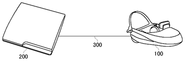
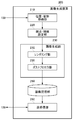
- FIG. 1 is a configuration diagram of an image generation system according to the present embodiment. It is a functional block diagram of the head mounted display which concerns on a premise technology. It is a functional block diagram of the image generation apparatus which concerns on a premise technology. It is a figure explaining the composition of the image generation system concerning the premise technology for superimposing a CG image on a camera image, and generating an augmented reality image. It is a functional block diagram of the head mounted display which concerns on 1st Embodiment.
- FIG. 1 is a functional configuration diagram of an image generation apparatus according to a first embodiment.
- FIG. 1 is an external view of a head mounted display 100.
- the head mounted display 100 is a display device mounted on the head of the user for viewing still images, moving images, and the like displayed on the display and listening to sounds, music, and the like output from headphones.
- a camera unit is mounted on the head mounted display 100, and while the user is wearing the head mounted display 100, the outside world can be photographed.
- the head mounted display 100 is an example of a “wearable display”.
- a method of generating an image displayed on the head mounted display 100 will be described.
- the method of generating an image according to the present embodiment is not limited to the head mounted display 100 in a narrow sense, but a glasses, glasses type display, glasses type camera, It can also be applied when wearing headphones, headsets (headphones with microphones), earphones, earrings, earpiece cameras, hats, camera hats, hair bands etc.
- FIG. 2 is a block diagram of an image generation system according to the present embodiment.
- the head mounted display 100 is connected to the image generation apparatus 200 by an interface 300 such as HDMI (High-Definition Multimedia Interface), which is a standard of a communication interface that transmits video and audio as digital signals, as an example. .
- HDMI High-Definition Multimedia Interface
- the image generation apparatus 200 predicts the position / attitude information of the head mounted display 100 from the current position / attitude information of the head mounted display 100 in consideration of the delay from the generation of an image to the display, and predicts the head mounted display 100 An image to be displayed on the head mounted display 100 is drawn on the premise of the position / posture information and transmitted to the head mounted display 100.
- An example of the image generation device 200 is a game machine.
- the image generation device 200 may be further connected to a server via a network.
- the server may provide the image generation apparatus 200 with an online application such as a game in which a plurality of users can participate via the network.
- the head mounted display 100 may be connected to a computer or a portable terminal instead of the image generation device 200.
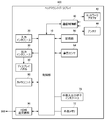
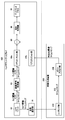
- FIG. 3 is a functional block diagram of the head mounted display 100 according to the base technology.
- the control unit 10 is a main processor that processes and outputs signals such as image signals and sensor signals, and instructions and data.
- the input interface 20 receives an operation signal and a setting signal from the user and supplies the control unit 10 with the operation signal and the setting signal.
- the output interface 30 receives an image signal from the control unit 10 and displays it on the display panel 32.
- the communication control unit 40 transmits data input from the control unit 10 to the outside through wired or wireless communication via the network adapter 42 or the antenna 44.
- the communication control unit 40 also receives data from the outside by wired or wireless communication via the network adapter 42 or the antenna 44, and outputs the data to the control unit 10.
- the storage unit 50 temporarily stores data to be processed by the control unit 10, parameters, operation signals and the like.
- the attitude sensor 64 detects position information of the head mounted display 100 and attitude information such as a rotation angle or tilt of the head mounted display 100.
- the attitude sensor 64 is realized by appropriately combining a gyro sensor, an acceleration sensor, an angular acceleration sensor, and the like.
- a motion sensor combining at least one or more of a three-axis geomagnetic sensor, a three-axis acceleration sensor, and a three-axis gyro (angular velocity) sensor may be used to detect front / rear, left / right, up / down motion of the user's head.
- the external input / output terminal interface 70 is an interface for connecting peripheral devices such as a USB (Universal Serial Bus) controller.
- the external memory 72 is an external memory such as a flash memory.
- the camera unit 80 includes components necessary for photographing such as a lens, an image sensor, and a distance measuring sensor, and supplies the photographed image of the outside world and depth information to the control unit 10.
- the control unit 10 controls focusing and zooming of the camera unit 80.
- the HDMI transmitting and receiving unit 90 transmits and receives digital signals of video and audio to and from the image generating apparatus 200 according to the HDMI.
- the HDMI transmitting and receiving unit 90 receives external images and depth information captured by the camera unit 80 from the control unit 10, and transmits the image to the image generation apparatus 200 through the HDMI transmission path.
- the HDMI transmitting and receiving unit 90 receives an image generated by the image generating apparatus 200 from the image generating apparatus 200 through the HDMI transmission path, and supplies the image to the control unit 10.
- the control unit 10 can supply an image or text data to the output interface 30 for display on the display panel 32, or can supply the image or text data to the communication control unit 40 to be transmitted to the outside.
- the current position / attitude information of the head mounted display 100 detected by the attitude sensor 64 is notified to the image generation apparatus 200 via the communication control unit 40 or the external input / output terminal interface 70.
- the HDMI transmitting / receiving unit 90 may transmit the current position / attitude information of the head mounted display 100 to the image generating apparatus 200.
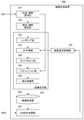
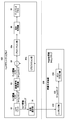
- FIG. 4 is a functional block diagram of an image generation apparatus 200 according to the base technology.
- the figure depicts a block diagram focusing on functions, and these functional blocks can be realized in various forms by hardware only, software only, or a combination thereof.
- At least a part of the functions of the image generation device 200 may be implemented on the head mounted display 100. Alternatively, at least a part of the functions of the image generation device 200 may be implemented on a server connected to the image generation device 200 via a network.
- the position and orientation acquisition unit 210 acquires current position and orientation information of the head mounted display 100 from the head mounted display 100.
- the viewpoint and line of sight setting unit 220 sets the viewpoint position and the line of sight direction of the user using the position and orientation information of the head mounted display 100 acquired by the position and orientation acquiring unit 210.
- the HDMI transmitting and receiving unit 280 receives an image of the real space captured by the camera unit 80 from the head mounted display 100, and supplies the image to the image signal processing unit 250.
- the image signal processing unit 250 performs image signal processing such as RGB conversion (demosaicing), white balance, color correction, noise reduction, and the like on the Raw image captured by the camera unit 80 of the head mounted display 100 (ISP (Image Signal Processing) ), And a distortion correction process is performed to remove distortion and the like due to the optical system of the camera unit 80.
- the image signal processing unit 250 supplies the RGB image subjected to the image signal processing and the distortion correction processing to the image generation unit 230.
- the image generation unit 230 reads out data necessary for generating computer graphics from the image storage unit 260, renders an object in the virtual space to generate a CG image, and a camera in real space provided by the image signal processing unit 250 By superimposing on an image, an augmented reality image is generated and output to the image storage unit 260.
- the image generation unit 230 includes a rendering unit 232, an AR superimposing unit 234, a post processing unit 236, a reprojection unit 240, and a distortion processing unit 242.
- the rendering unit 232 renders an object in a virtual space viewed from the viewpoint position of the user wearing the head mounted display 100 according to the viewpoint position and the line of sight of the user set by the viewpoint / line of sight setting unit 220. It is supplied to the superimposing unit 234.
- the AR superimposing unit 234 generates an augmented reality image by superimposing the CG image generated by the rendering unit 232 on the camera image supplied from the image signal processing unit 250, and supplies the augmented reality image to the post processing unit 236.
- the post processing unit 236 performs post processing such as depth of field adjustment, tone mapping, and anti-aliasing on the augmented reality image, and the augmented reality image in which the virtual object is superimposed on the image in real space is smooth and natural Post-process to make it visible.
- the reprojection unit 240 receives the latest position / attitude information of the head mounted display 100 from the position / attitude acquiring unit 210, performs reprojection processing on the post-processed augmented reality image, and Convert to the image seen from the latest viewpoint position and gaze direction.
- the movement of the head mounted display 100 is detected, the CPU issues a drawing command, the GPU (Graphics Processing Unit) executes rendering, and the drawn image is output to the head mounted display 100.
- draw is performed at a frame rate of, for example, 60 fps (frames / second), and there is a delay of one frame from detection of movement of the head mounted display 100 to output of an image. This is about 16.67 ms at a frame rate of 60 fps, which is a sufficient time for a human to detect a shift.
- time warp or “reprojection” is performed to correct the rendered image in accordance with the latest position and posture of the head mounted display 100 so that it is difficult for a human to detect a deviation.
- the distortion processing unit 242 performs processing to distort and distort the image according to distortion generated in the optical system of the head mount display 100 with respect to the augmented reality image subjected to the reprojection processing, and the image storage unit 260
- the distortion processing unit 242 performs processing to distort and distort the image according to distortion generated in the optical system of the head mount display 100 with respect to the augmented reality image subjected to the reprojection processing, and the image storage unit 260
- the HDMI transmitting and receiving unit 280 reads the frame data of the augmented reality image generated by the image generating unit 230 from the image storage unit 260, and transmits the frame data to the head mounted display 100 according to the HDMI.
- FIG. 5 is a diagram for explaining the configuration of an image generation system according to the base technology for generating an augmented reality image by superimposing a CG image on a camera image.
- main configurations of the head mounted display 100 and the image generation apparatus 200 for generating an augmented reality image are illustrated and described.
- An external camera image captured by the camera unit 80 of the head mounted display 100 is transmitted to the image generation apparatus 200 and supplied to the image signal processing unit 250.
- the image signal processing unit 250 performs image signal processing and distortion correction processing on the camera image, and supplies it to the AR superimposing unit 234.
- the rendering unit 232 of the image generation device 200 generates a virtual object viewed from the viewpoint position / line of sight of the user wearing the head mounted display 100 and supplies the virtual object to the AR superimposing unit 234.
- the AR superimposing unit 234 superimposes a CG image on a camera image to generate an augmented reality image.
- the post processing unit 236 performs post processing on the augmented reality image.
- the reprojection unit 240 transforms the post-processed augmented reality image so as to fit the latest viewpoint position and gaze direction.
- the distortion processing unit 242 performs distortion processing on the augmented reality image after reprojection.
- the final RGB image after distortion processing is transmitted to the head mounted display 100 and displayed on the display panel 32.
- the camera image is superimposed in accordance with the frame rate of rendering of the CG image by the image generation apparatus 200. Since rendering takes time, the frame rate of rendering of the virtual space by the rendering unit 232 is slower than the frame rate of imaging of the real space by the camera unit 80. For example, even if shooting at 120 fps is performed by the camera unit 80, rendering may be possible only at 60 fps. As a result, the frame rate of the see-through image displayed on the display panel of the head mounted display 100 decreases in accordance with the frame rate of rendering, and the see-through image becomes jerky and results of not seeing reality even when viewing augmented reality images It becomes.
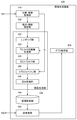
- FIG. 6 is a functional configuration diagram of the head mounted display 100 according to the first embodiment.
- the posture estimation unit 81 estimates posture information (position and rotation) of the head mounted display 100 from feature points of the image captured by the camera unit 80.
- the transmission and reception unit 92 transmits the posture information estimated by the posture estimation unit 81 to the image generation apparatus 200.
- the image signal processing unit 82 performs image signal processing such as RGB conversion (demosaicing), white balance, color correction, noise reduction, and the like on the Raw image captured by the camera unit 80, and further the optical system of the camera unit 80. A distortion correction process is performed to remove distortion and the like.
- the image signal processing unit 82 supplies the camera image subjected to the image signal processing and distortion correction processing to the control unit 10.
- the reprojection unit 84 performs reprojection processing on the camera image based on the latest position / attitude information of the head mounted display 100 detected by the attitude estimation unit 81 or the attitude sensor 64, and the latest viewpoint of the head mounted display 100. Convert to an image that can be seen from the position and gaze direction.
- the distortion processing unit 86 performs processing to deform and distort the image of the camera image subjected to the reprojection processing in accordance with distortion generated in the optical system of the head mount display 100, and the distortion-processed camera image Are supplied to the control unit 10.
- the AR superimposing unit 88 generates an augmented reality image by superimposing the alpha-added CG image generated by the image generation device 200 on the camera image subjected to the distortion processing, and supplies the augmented reality image to the control unit 10.
- the transmitting and receiving unit 92 transmits and receives digital signals of video and audio to and from the image generating apparatus 200.
- the transmission / reception unit 92 receives depth information of a camera image from the control unit 10 and transmits the depth information to the image generation apparatus 200.
- the transmitting and receiving unit 92 receives an image including the depth information generated by the image generating apparatus 200 from the image generating apparatus 200 and supplies the image to the control unit 10.
- FIG. 7 is a functional block diagram of the image generation apparatus 200 according to the first embodiment.
- the transmission / reception unit 282 receives depth information of an image of the real space taken by the camera unit 80 from the head mounted display 100 and supplies the depth information to the depth acquisition unit 252.
- the image generation unit 230 reads data necessary for generating computer graphics from the image storage unit 260, renders an object in the virtual space to generate a CG image, and a camera image of the real space provided from the depth acquisition unit 252
- the CG image with alpha is generated from the CG image on the basis of the depth information, and is output to the image storage unit 260.
- the image generation unit 230 includes a rendering unit 232, an alpha-added image generation unit 233, a post-processing unit 236, a reprojection unit 240, and a distortion processing unit 242.
- the rendering unit 232 renders an object in a virtual space viewed from the viewpoint position of the user who wears the head mounted display 100 according to the viewpoint position and the gaze direction of the user set by the viewpoint / gaze setting unit 220 and CG An image is generated and supplied to the alpha-added image generation unit 233.
- the alpha-added image generation unit 233 generates an alpha-added CG image from the CG image based on the depth information of the camera image given from the depth acquisition unit 252. Specifically, the positional relationship between an object in the real space and an object in the virtual space is determined, and in the CG image, the area of the background of the virtual object or the occluded area hidden behind objects by the real space object in front of the virtual object. Sets the alpha value to be transparent.
- the alpha-added image generation unit 233 provides the post-processing unit 236 with the alpha-added CG image.
- the post-processing unit 236 performs post-processing such as depth of field adjustment, tone mapping, and anti-aliasing on the alpha-added CG image to post-process the alpha-added CG image so that it looks natural and smooth.
- the alpha value can also be set so that the boundary between the CG image and the camera image is translucent.
- the reprojection unit 240 receives the latest position / attitude information of the head mounted display 100 from the position / attitude acquiring unit 210, performs reprojection processing on the post-processed alpha-added CG image, and executes the head mounted display 100. Convert to the image seen from the latest viewpoint position and gaze direction of.
- the distortion processing unit 242 performs processing to deform and distort the CG image with alpha subjected to the reprojection processing in accordance with the distortion generated in the optical system of the head mounted display 100, and stores the image in the image storage unit 260. Do.
- the transmission / reception unit 282 reads the frame data of the CG image with alpha generated by the image generation unit 230 from the image storage unit 260, and transmits the CG image with alpha to the head mounted display 100 via the communication interface capable of transmitting the RGBA image signal.
- the RGBA image signal is an image signal in which an alpha value is added to the value of each color of red, green and blue for each pixel.
- FIG. 8 is a view for explaining the arrangement of an image generation system according to the first embodiment for generating an augmented reality image by superimposing a CG image on a camera image.
- An external camera image taken by the camera unit 80 of the head mounted display 100, depth information, and a timestamp are supplied to the image signal processing unit 82. Also, the camera image and the time stamp are supplied to the posture estimation unit 81.
- the attitude estimation unit 81 estimates the attitude information of the head mounted display 100 from the camera image, and supplies the attitude information and the time stamp to the rendering unit 232.
- the image signal processing unit 82 performs image signal processing and distortion correction processing on the camera image, and gives the camera image and the timestamp to the reprojection unit 84.
- the image signal processing unit 82 transmits the depth information to the image generation apparatus 200 and supplies the depth information to the alpha-added image generation unit 233.
- the rendering unit 232 of the image generation device 200 generates a virtual object viewed from the viewpoint position / line of sight of the user who wears the head mounted display 100, and supplies the CG image and the time stamp to the alpha-added image generation unit 233.
- the time stamp is passed from the alpha-added image generation unit 233 to the post-processing unit 236 and the reprojection unit 240.
- the alpha-added image generation unit 233 generates an alpha-added CG image from the CG image based on the depth information.
- the post processing unit 236 performs post processing on the alpha-added CG image.
- the reprojection unit 240 converts the post-processed alpha-added CG image so that it matches the latest viewpoint position and gaze direction based on the time stamp.
- the distortion processing unit 242 performs distortion processing on the alpha-added CG image after reprojection.
- the final RGBA image after distortion processing is transmitted to the head mounted display 100 and supplied to the AR superimposing unit 88.
- the RGBA image is a CG image in which an alpha value is set to indicate that the area on which the camera image is to be superimposed is transparent.
- the reprojection unit 84 of the head mounted display 100 converts the camera image subjected to the image signal processing and the distortion correction processing so as to match the latest viewpoint position and line of sight direction with reference to the time stamp, and generates a distortion processing unit 86.
- the distortion processing unit 86 performs distortion processing on the camera image after reprojection.
- the AR superimposing unit 88 generates an augmented reality image by superimposing the alpha-added CG image supplied from the image generation device 200 on the distortion-processed camera image.
- the generated augmented reality image is displayed on the display panel 32.
- the image generation system of the first embodiment since the camera image photographed by the camera unit 80 of the head mounted display 100 is not transferred to the image generation apparatus 200, the camera image photographed at a high frame rate is generated It can be superimposed on the CG image generated by the device 200. Therefore, the see-through image is not interrupted, and a user watching the augmented reality image on the head mounted display 100 can have a sense of connection with the real world.
- the configuration of the head mounted display 100 is basically the same as that shown in FIG. 6, but the reprojection unit 84 is configured to include a first reprojection unit 84a for a camera image and a second reprojection for a CG image. It has the part 84b.
- FIG. 9 is a functional block diagram of an image generation apparatus 200 according to the second embodiment.
- the image generation apparatus 2000 does not receive the camera image and the depth information captured by the camera unit 80 from the head mounted display 100.
- the image generation unit 230 reads data necessary for generation of computer graphics from the image storage unit 260, renders an object in the virtual space to generate a CG image, performs post processing, and outputs the CG image to the image storage unit 260.
- the image generation unit 230 includes a rendering unit 232 and a post processing unit 236.
- the rendering unit 232 renders an object in a virtual space viewed from the viewpoint position of the user who wears the head mounted display 100 according to the viewpoint position and the gaze direction of the user set by the viewpoint / gaze setting unit 220 and CG An image is generated and given to the post processing unit 236.
- the post processing unit 236 performs post processing on the CG image, performs post processing so that the CG image looks natural and smooth, and stores it in the image storage unit 260.
- the transmission / reception unit 282 reads frame data of a CG image including the alpha value and the depth information generated by the image generation unit 230 from the image storage unit 260, and head mounts as an RGBAD image via a communication interface capable of transmitting an RGBAD image signal. Transmit to the display 100.
- the RGBAD image signal is an image signal in which an alpha value and a depth value are added to the values of each color of red, green and blue for each pixel.
- FIG. 10 is a view for explaining the arrangement of an image generation system according to the second embodiment for generating an augmented reality image by superimposing a CG image on a camera image.
- An external camera image taken by the camera unit 80 of the head mounted display 100, depth information, and a timestamp are supplied to the image signal processing unit 82. Also, the camera image and the time stamp are supplied to the posture estimation unit 81.
- the attitude estimation unit 81 estimates the attitude information of the head mounted display 100 from the camera image, and supplies the attitude information and the time stamp to the rendering unit 232.
- the image signal processing unit 82 performs image signal processing and distortion correction processing on the camera image, and gives the camera image, depth information, and a timestamp to the first reprojection unit 84 a.
- the rendering unit 232 of the image generation device 200 generates a virtual object viewed from the viewpoint position and the gaze direction of the user wearing the head mounted display 100, and gives a CG image and a time stamp to the post processing unit 236.
- the post-processing unit 236 performs post-processing on the CG image, transmits it as an RGBAD image including an alpha value and depth information to the head mounted display 100 together with the time stamp, and supplies it to the reprojection unit 84 b.
- the first reprojection unit 84a of the head mounted display 100 converts the camera image subjected to the image signal processing and the distortion correction processing based on the time stamp so as to fit the latest viewpoint position and line of sight, and performs AR superposition. Supply to the section 88.
- the second reprojection unit 84 b of the head mounted display 100 converts the CG image based on the time stamp so as to fit the latest viewpoint position and line of sight direction, and supplies the converted image to the AR superimposing unit 88.
- the second reprojection unit 84b can perform reprojection processing in consideration of not only the rotation component but also the translation component using the depth information.
- the first reprojection unit 84a for the camera image and the second reprojection unit 84b for the CG image are separated because the rendering of the image generation apparatus 200 takes time.
- the difference amount to be corrected is different depending on the reprojection. For example, while reprojection of one frame ahead is performed by the first reprojection unit 84a, reprojection of two frame ahead must be performed by the second reprojection unit 84b.
- the AR superimposing unit 88 superimposes the CG image on which the reprojection processing has been performed by the second reprojection unit 84 b on the camera image on which the reprojection processing has been performed by the first reprojection unit 84 a.
- An image is generated and supplied to the distortion processing unit 86.
- the AR superimposing unit 88 can perform superimposing processing in pixel units using both depth information.
- the distortion processor 86 performs distortion processing on the augmented reality image.
- the generated augmented reality image is displayed on the display panel 32.
- FIG. 11 is a view for explaining a modification of the configuration of the image generation system according to the second embodiment for generating an augmented reality image by superimposing a CG image on a camera image. Points different from the configuration of FIG. 10 will be described.
- the first reprojection unit 84 a is provided downstream of the AR superimposing unit 88, and the image signal processing unit 82 directly supplies the camera image, the depth information, and the time stamp to the AR superposing unit 88.
- the timestamp is passed from the AR superimposing unit 88 to the first reprojection unit 84 a.
- the second reprojection unit 84b converts the CG image to the latest viewpoint position and line of sight direction based on the time stamp, and supplies the converted image to the AR superimposing unit 88.
- the AR superimposing unit 88 generates an augmented reality image by superimposing the CG image on which the reprojection processing has been performed by the second reprojection unit 84 b on the camera image.
- the first reprojection unit 84a predicts the output timing of the augmented reality image on the basis of the time stamp, converts the augmented reality image to fit the viewpoint position / line of sight at the output timing, and supplies the converted image to the distortion processing unit 86.
- the image generation system of the second embodiment as in the first embodiment, it is possible to superimpose a camera image photographed at a high frame rate on a CG image, so that the see-through image becomes broken.
- the CG image is transmitted to the head mounted display 100 including the depth information
- the head mounted display 100 can superimpose the camera image with high accuracy by referring to the depth information for each pixel.
- the present invention can be applied not only to the image see-through type but also to the optical see-through type head mounted display 100.
- prediction conversion is possible not only for rotational components but also for translational components in the reprojection unit 84b of the head mount display 100. Three-dimensional conversion is performed for each pixel to perform reprojection processing with high accuracy. It can be applied.
- the CG image since the CG image is subjected to reprojection processing on the head mounted display 100 side, the CG image can be converted to fit the viewpoint position and the line of sight immediately before displaying on the display panel 32, and the followability can be achieved with high accuracy. Can provide augmented reality images.
- the image generation apparatus 200 can use more resources for rendering.
- the posture estimation unit 81 may be provided in the image generation apparatus 200 as a modification.
- a video transmission (video see-through) type head mounted display has been described as an example, but an optical transmission (optical see-through) type in which the display unit is configured with a half mirror etc.
- the present embodiment can also be applied to the case of a head mounted display.
- the depth information of the camera image and the depth information of the CG image are compared, and the CG image is deleted for the region where the real space object exists in front of the virtual space object. Make it visible through the real space.
- DESCRIPTION OF SYMBOLS 10 control part 20 input interface, 30 output interface, 32 display panel, 40 communication control part, 42 network adapter, 44 antenna, 50 storage part, 64 attitude sensor, 70 external input / output terminal interface, 72 external memory, 80 camera unit , 81 attitude estimation unit, 82 image signal processing unit, 84 reprojection unit, 86 distortion processing unit, 88 AR superposition unit, 90 HDMI transmission / reception unit, 92 transmission / reception unit, 100 head mounted display, 200 image generation device, 210 position / attitude Acquisition unit, 220 viewpoint / line-of-sight setting unit, 230 image generation unit, 232 rendering unit, 233 image generation unit with alpha, 234 AR superposition unit, 236 post-processing unit 240 re-projection portion, 242 distortion processing unit, 250 an image signal processing unit, 252 depth obtaining section, 260 image storage unit, 280 HDMI receiving unit, 282 reception unit, 300 interface.
- the invention can be used in the field of image generation.
Landscapes
- Engineering & Computer Science (AREA)
- Physics & Mathematics (AREA)
- General Physics & Mathematics (AREA)
- Theoretical Computer Science (AREA)
- Computer Hardware Design (AREA)
- Computer Graphics (AREA)
- General Engineering & Computer Science (AREA)
- Software Systems (AREA)
- Optics & Photonics (AREA)
- Computing Systems (AREA)
- Geometry (AREA)
- Multimedia (AREA)
- Signal Processing (AREA)
- Processing Or Creating Images (AREA)
- Image Generation (AREA)
- Controls And Circuits For Display Device (AREA)
Abstract
Selon l'invention, une unité de rendu (232) rend un objet dans un espace virtuel et génère une image infographique. Une unité de post-traitement (236) réalise un post-traitement sur l'image infographique. Une unité d'émission/réception (282) transmet à un visiocasque (100) l'image infographique qui a été soumise au post-traitement, conjointement avec des informations de profondeur, de sorte que l'image infographique soit superposée sur une image capturée dans un espace réel.
Priority Applications (1)
| Application Number | Priority Date | Filing Date | Title |
|---|---|---|---|
| US16/762,786 US11204502B2 (en) | 2017-11-20 | 2018-11-13 | Image generation apparatus, head mounted display, image generation system, image generation method, and program |
Applications Claiming Priority (2)
| Application Number | Priority Date | Filing Date | Title |
|---|---|---|---|
| JP2017-222897 | 2017-11-20 | ||
| JP2017222897A JP6978289B2 (ja) | 2017-11-20 | 2017-11-20 | 画像生成装置、ヘッドマウントディスプレイ、画像生成システム、画像生成方法、およびプログラム |
Publications (1)
| Publication Number | Publication Date |
|---|---|
| WO2019098198A1 true WO2019098198A1 (fr) | 2019-05-23 |
Family
ID=66539649
Family Applications (1)
| Application Number | Title | Priority Date | Filing Date |
|---|---|---|---|
| PCT/JP2018/042003 WO2019098198A1 (fr) | 2017-11-20 | 2018-11-13 | Dispositif, système et procédé de génération d'images, visiocasque et programme associé |
Country Status (3)
| Country | Link |
|---|---|
| US (1) | US11204502B2 (fr) |
| JP (1) | JP6978289B2 (fr) |
| WO (1) | WO2019098198A1 (fr) |
Families Citing this family (5)
| Publication number | Priority date | Publication date | Assignee | Title |
|---|---|---|---|---|
| JP7377014B2 (ja) * | 2019-07-10 | 2023-11-09 | 株式会社ソニー・インタラクティブエンタテインメント | 画像表示装置、画像表示システムおよび画像表示方法 |
| WO2021006191A1 (fr) * | 2019-07-10 | 2021-01-14 | 株式会社ソニー・インタラクティブエンタテインメント | Dispositif d'affichage d'image, système d'affichage d'image et procédé d'affichage d'image |
| JP7217206B2 (ja) | 2019-07-10 | 2023-02-02 | 株式会社ソニー・インタラクティブエンタテインメント | 画像表示装置、画像表示システムおよび画像表示方法 |
| JP7429633B2 (ja) | 2020-12-08 | 2024-02-08 | Kddi株式会社 | 情報処理システム、端末、サーバ及びプログラム |
| JP7557442B2 (ja) | 2021-08-26 | 2024-09-27 | Kddi株式会社 | 3dcgレンダリング装置、システム、方法およびプログラム |
Citations (4)
| Publication number | Priority date | Publication date | Assignee | Title |
|---|---|---|---|---|
| WO2015098292A1 (fr) * | 2013-12-25 | 2015-07-02 | ソニー株式会社 | Dispositif de traitement d'image, procédé de traitement d'image, programme informatique et système de traitement d'image |
| JP2015191314A (ja) * | 2014-03-27 | 2015-11-02 | キヤノン株式会社 | 画像処理装置、画像処理システム及び画像処理方法 |
| JP2016024273A (ja) * | 2014-07-17 | 2016-02-08 | 株式会社ソニー・コンピュータエンタテインメント | 立体画像提示装置、立体画像提示方法、およびヘッドマウントディスプレイ |
| US20160364904A1 (en) * | 2015-06-12 | 2016-12-15 | Google Inc. | Electronic display stabilization for head mounted display |
Family Cites Families (4)
| Publication number | Priority date | Publication date | Assignee | Title |
|---|---|---|---|---|
| GB2523740B (en) * | 2014-02-26 | 2020-10-14 | Sony Interactive Entertainment Inc | Image encoding and display |
| JP6087453B1 (ja) * | 2016-02-04 | 2017-03-01 | 株式会社コロプラ | 仮想空間の提供方法、およびプログラム |
| US11024014B2 (en) * | 2016-06-28 | 2021-06-01 | Microsoft Technology Licensing, Llc | Sharp text rendering with reprojection |
| US10394313B2 (en) * | 2017-03-15 | 2019-08-27 | Microsoft Technology Licensing, Llc | Low latency cross adapter VR presentation |
-
2017
- 2017-11-20 JP JP2017222897A patent/JP6978289B2/ja active Active
-
2018
- 2018-11-13 US US16/762,786 patent/US11204502B2/en active Active
- 2018-11-13 WO PCT/JP2018/042003 patent/WO2019098198A1/fr active Application Filing
Patent Citations (4)
| Publication number | Priority date | Publication date | Assignee | Title |
|---|---|---|---|---|
| WO2015098292A1 (fr) * | 2013-12-25 | 2015-07-02 | ソニー株式会社 | Dispositif de traitement d'image, procédé de traitement d'image, programme informatique et système de traitement d'image |
| JP2015191314A (ja) * | 2014-03-27 | 2015-11-02 | キヤノン株式会社 | 画像処理装置、画像処理システム及び画像処理方法 |
| JP2016024273A (ja) * | 2014-07-17 | 2016-02-08 | 株式会社ソニー・コンピュータエンタテインメント | 立体画像提示装置、立体画像提示方法、およびヘッドマウントディスプレイ |
| US20160364904A1 (en) * | 2015-06-12 | 2016-12-15 | Google Inc. | Electronic display stabilization for head mounted display |
Also Published As
| Publication number | Publication date |
|---|---|
| JP2019095916A (ja) | 2019-06-20 |
| US20210191124A1 (en) | 2021-06-24 |
| US11204502B2 (en) | 2021-12-21 |
| JP6978289B2 (ja) | 2021-12-08 |
Similar Documents
| Publication | Publication Date | Title |
|---|---|---|
| US11119319B2 (en) | Rendering device, head-mounted display, image transmission method, and image correction method | |
| JP6732716B2 (ja) | 画像生成装置、画像生成システム、画像生成方法、およびプログラム | |
| WO2019098198A1 (fr) | Dispositif, système et procédé de génération d'images, visiocasque et programme associé | |
| US11373379B2 (en) | Image generation apparatus and image generation method for generating augmented reality images based on user interaction | |
| US11120632B2 (en) | Image generating apparatus, image generating system, image generating method, and program | |
| US11003408B2 (en) | Image generating apparatus and image generating method | |
| JP2017097122A (ja) | 情報処理装置および画像生成方法 | |
| JP7234021B2 (ja) | 画像生成装置、画像生成システム、画像生成方法、およびプログラム | |
| WO2016063617A1 (fr) | Dispositif de génération d'images, dispositif d'extraction d'images, procédé de génération d'images, et procédé d'extraction d'images | |
| WO2020129115A1 (fr) | Système de traitement d'informations, procédé de traitement d'informations et programme informatique | |
| US11100716B2 (en) | Image generating apparatus and image generation method for augmented reality | |
| JP7047085B2 (ja) | 画像生成装置、画像生成方法、およびプログラム | |
| JP7429761B2 (ja) | 画像表示装置、画像表示システムおよび画像表示方法 | |
| JP7377014B2 (ja) | 画像表示装置、画像表示システムおよび画像表示方法 | |
| WO2021006191A1 (fr) | Dispositif d'affichage d'image, système d'affichage d'image et procédé d'affichage d'image | |
| US20240236290A9 (en) | Image generation device, program, image generation method, and image displaying system | |
| WO2022255058A1 (fr) | Dispositif de traitement d'informations et procédé de génération d'image | |
| EP4261768A1 (fr) | Système et procédé de traitement d'image | |
| WO2021106136A1 (fr) | Dispositif de terminal d'affichage |
Legal Events
| Date | Code | Title | Description |
|---|---|---|---|
| 121 | Ep: the epo has been informed by wipo that ep was designated in this application |
Ref document number: 18877568 Country of ref document: EP Kind code of ref document: A1 |
|
| 122 | Ep: pct application non-entry in european phase |
Ref document number: 18877568 Country of ref document: EP Kind code of ref document: A1 |