WO2022255058A1 - Dispositif de traitement d'informations et procédé de génération d'image - Google Patents
Dispositif de traitement d'informations et procédé de génération d'image Download PDFInfo
- Publication number
- WO2022255058A1 WO2022255058A1 PCT/JP2022/020149 JP2022020149W WO2022255058A1 WO 2022255058 A1 WO2022255058 A1 WO 2022255058A1 JP 2022020149 W JP2022020149 W JP 2022020149W WO 2022255058 A1 WO2022255058 A1 WO 2022255058A1
- Authority
- WO
- WIPO (PCT)
- Prior art keywords
- image
- display
- head
- pattern
- generation unit
- Prior art date
Links
- 230000010365 information processing Effects 0.000 title claims description 49
- 238000000034 method Methods 0.000 title claims description 18
- 238000012545 processing Methods 0.000 claims abstract description 63
- 230000008569 process Effects 0.000 claims description 11
- 238000013461 design Methods 0.000 claims description 5
- 230000006870 function Effects 0.000 description 38
- 238000003384 imaging method Methods 0.000 description 23
- 210000003128 head Anatomy 0.000 description 12
- 238000004891 communication Methods 0.000 description 11
- 230000003287 optical effect Effects 0.000 description 7
- 238000010586 diagram Methods 0.000 description 5
- 239000000284 extract Substances 0.000 description 4
- 230000033001 locomotion Effects 0.000 description 4
- 230000007246 mechanism Effects 0.000 description 4
- 238000005516 engineering process Methods 0.000 description 2
- 230000015654 memory Effects 0.000 description 2
- 238000012986 modification Methods 0.000 description 2
- 230000004048 modification Effects 0.000 description 2
- 230000001133 acceleration Effects 0.000 description 1
- 230000008859 change Effects 0.000 description 1
- 230000000295 complement effect Effects 0.000 description 1
- 238000001514 detection method Methods 0.000 description 1
- 230000006866 deterioration Effects 0.000 description 1
- 210000005069 ears Anatomy 0.000 description 1
- 210000000887 face Anatomy 0.000 description 1
- 238000007654 immersion Methods 0.000 description 1
- 239000004973 liquid crystal related substance Substances 0.000 description 1
- 230000004807 localization Effects 0.000 description 1
- 238000013507 mapping Methods 0.000 description 1
- 239000000463 material Substances 0.000 description 1
- 229910044991 metal oxide Inorganic materials 0.000 description 1
- 150000004706 metal oxides Chemical class 0.000 description 1
- 230000002093 peripheral effect Effects 0.000 description 1
- 238000009877 rendering Methods 0.000 description 1
- 239000004065 semiconductor Substances 0.000 description 1
- 230000001360 synchronised effect Effects 0.000 description 1
Images


Classifications
-
- A—HUMAN NECESSITIES
- A63—SPORTS; GAMES; AMUSEMENTS
- A63F—CARD, BOARD, OR ROULETTE GAMES; INDOOR GAMES USING SMALL MOVING PLAYING BODIES; VIDEO GAMES; GAMES NOT OTHERWISE PROVIDED FOR
- A63F13/00—Video games, i.e. games using an electronically generated display having two or more dimensions
- A63F13/20—Input arrangements for video game devices
- A63F13/21—Input arrangements for video game devices characterised by their sensors, purposes or types
- A63F13/211—Input arrangements for video game devices characterised by their sensors, purposes or types using inertial sensors, e.g. accelerometers or gyroscopes
-
- A—HUMAN NECESSITIES
- A63—SPORTS; GAMES; AMUSEMENTS
- A63F—CARD, BOARD, OR ROULETTE GAMES; INDOOR GAMES USING SMALL MOVING PLAYING BODIES; VIDEO GAMES; GAMES NOT OTHERWISE PROVIDED FOR
- A63F13/00—Video games, i.e. games using an electronically generated display having two or more dimensions
- A63F13/20—Input arrangements for video game devices
- A63F13/21—Input arrangements for video game devices characterised by their sensors, purposes or types
- A63F13/212—Input arrangements for video game devices characterised by their sensors, purposes or types using sensors worn by the player, e.g. for measuring heart beat or leg activity
-
- A—HUMAN NECESSITIES
- A63—SPORTS; GAMES; AMUSEMENTS
- A63F—CARD, BOARD, OR ROULETTE GAMES; INDOOR GAMES USING SMALL MOVING PLAYING BODIES; VIDEO GAMES; GAMES NOT OTHERWISE PROVIDED FOR
- A63F13/00—Video games, i.e. games using an electronically generated display having two or more dimensions
- A63F13/20—Input arrangements for video game devices
- A63F13/21—Input arrangements for video game devices characterised by their sensors, purposes or types
- A63F13/213—Input arrangements for video game devices characterised by their sensors, purposes or types comprising photodetecting means, e.g. cameras, photodiodes or infrared cells
-
- A—HUMAN NECESSITIES
- A63—SPORTS; GAMES; AMUSEMENTS
- A63F—CARD, BOARD, OR ROULETTE GAMES; INDOOR GAMES USING SMALL MOVING PLAYING BODIES; VIDEO GAMES; GAMES NOT OTHERWISE PROVIDED FOR
- A63F13/00—Video games, i.e. games using an electronically generated display having two or more dimensions
- A63F13/25—Output arrangements for video game devices
-
- A—HUMAN NECESSITIES
- A63—SPORTS; GAMES; AMUSEMENTS
- A63F—CARD, BOARD, OR ROULETTE GAMES; INDOOR GAMES USING SMALL MOVING PLAYING BODIES; VIDEO GAMES; GAMES NOT OTHERWISE PROVIDED FOR
- A63F13/00—Video games, i.e. games using an electronically generated display having two or more dimensions
- A63F13/40—Processing input control signals of video game devices, e.g. signals generated by the player or derived from the environment
- A63F13/42—Processing input control signals of video game devices, e.g. signals generated by the player or derived from the environment by mapping the input signals into game commands, e.g. mapping the displacement of a stylus on a touch screen to the steering angle of a virtual vehicle
- A63F13/428—Processing input control signals of video game devices, e.g. signals generated by the player or derived from the environment by mapping the input signals into game commands, e.g. mapping the displacement of a stylus on a touch screen to the steering angle of a virtual vehicle involving motion or position input signals, e.g. signals representing the rotation of an input controller or a player's arm motions sensed by accelerometers or gyroscopes
-
- A—HUMAN NECESSITIES
- A63—SPORTS; GAMES; AMUSEMENTS
- A63F—CARD, BOARD, OR ROULETTE GAMES; INDOOR GAMES USING SMALL MOVING PLAYING BODIES; VIDEO GAMES; GAMES NOT OTHERWISE PROVIDED FOR
- A63F13/00—Video games, i.e. games using an electronically generated display having two or more dimensions
- A63F13/50—Controlling the output signals based on the game progress
- A63F13/52—Controlling the output signals based on the game progress involving aspects of the displayed game scene
- A63F13/525—Changing parameters of virtual cameras
- A63F13/5255—Changing parameters of virtual cameras according to dedicated instructions from a player, e.g. using a secondary joystick to rotate the camera around a player's character
-
- A—HUMAN NECESSITIES
- A63—SPORTS; GAMES; AMUSEMENTS
- A63F—CARD, BOARD, OR ROULETTE GAMES; INDOOR GAMES USING SMALL MOVING PLAYING BODIES; VIDEO GAMES; GAMES NOT OTHERWISE PROVIDED FOR
- A63F13/00—Video games, i.e. games using an electronically generated display having two or more dimensions
- A63F13/60—Generating or modifying game content before or while executing the game program, e.g. authoring tools specially adapted for game development or game-integrated level editor
- A63F13/65—Generating or modifying game content before or while executing the game program, e.g. authoring tools specially adapted for game development or game-integrated level editor automatically by game devices or servers from real world data, e.g. measurement in live racing competition
-
- G—PHYSICS
- G06—COMPUTING; CALCULATING OR COUNTING
- G06F—ELECTRIC DIGITAL DATA PROCESSING
- G06F3/00—Input arrangements for transferring data to be processed into a form capable of being handled by the computer; Output arrangements for transferring data from processing unit to output unit, e.g. interface arrangements
- G06F3/01—Input arrangements or combined input and output arrangements for interaction between user and computer
- G06F3/03—Arrangements for converting the position or the displacement of a member into a coded form
- G06F3/033—Pointing devices displaced or positioned by the user, e.g. mice, trackballs, pens or joysticks; Accessories therefor
- G06F3/0346—Pointing devices displaced or positioned by the user, e.g. mice, trackballs, pens or joysticks; Accessories therefor with detection of the device orientation or free movement in a 3D space, e.g. 3D mice, 6-DOF [six degrees of freedom] pointers using gyroscopes, accelerometers or tilt-sensors
Definitions
- the present disclosure relates to technology for estimating at least one of the position and orientation of a head mounted display based on an image captured around the head mounted display.
- HMD head-mounted display
- SLAM Simultaneous Localization And Mapping
- SLAM is known as a technique for estimating the position and/or orientation of an HMD.
- SLAM is a technology that simultaneously performs self-position estimation and environment map creation, and estimates the position and/or orientation of the HMD by tracking feature points using images captured by the camera mounted on the HMD. It becomes possible to
- an object of the present disclosure is to provide a technique for estimating at least one of the position and orientation of an HMD with high accuracy in an environment where a display device different from the HMD exists.
- an information processing apparatus performs a process of estimating at least one of the position and orientation of a head mounted display based on an image captured around the head mounted display.
- a processing unit and an image generation unit that generates a display image to be displayed on a display device different from the head-mounted display are provided.
- the image generation unit generates a display image including at least a part of the design, which is a still image.
- An image generation method includes the steps of estimating at least one of the position and orientation of the head-mounted display based on an image captured around the head-mounted display; and generating a display image to be displayed on a different display device, the display image including at least a part of a pattern that is a still image.
- FIG. 4 is a diagram showing an example of a display image displayed on the display panel; (a) and (b) are diagrams showing examples of images captured by an imaging device.
- FIG. 4 is a diagram showing an example of an image displayed on an output device;
- FIG. 10 is a diagram showing an example of a setting screen for turning on/off the pattern display function;
- FIG. 5 is a diagram showing an example of a setting screen displayed on the display panel;
- FIG. 1 shows a configuration example of an information processing system 1 in an embodiment.
- the information processing system 1 includes an information processing device 10, a recording device 11, a head mounted display (HMD) 100, an input device 16 operated by a user's fingers, and an output device 15 for outputting images and sounds.
- the output device 15 is a display device different from the HMD 100 and may be a stationary television.
- the information processing device 10 is connected to an external network 2 such as the Internet via an access point (AP) 17 .
- the AP 17 has the functions of a wireless access point and router, and the information processing device 10 may be connected to the AP 17 by a cable or by a known wireless communication protocol.
- the recording device 11 records applications such as system software and game software.
- the information processing device 10 may download game software from the content server to the recording device 11 via the network 2 .
- the information processing device 10 executes a game program and supplies game image data and audio data to the HMD 100 .
- the information processing device 10 and the HMD 100 may be connected by a known wireless communication protocol, or may be connected by a cable.
- the HMD 100 is a display device that displays an image on a display panel positioned in front of the user's eyes when worn by the user.
- the HMD 100 separately displays a left-eye image on the left-eye display panel and a right-eye image on the right-eye display panel. These images constitute parallax images viewed from left and right viewpoints, and achieve stereoscopic vision. Since the user views the display panel through an optical lens, the information processing apparatus 10 supplies the HMD 100 with parallax image data corrected for optical distortion caused by the lens.
- a user wearing the HMD 100 does not need the output device 15, but by preparing the output device 15, another user can view the display image of the output device 15.
- the information processing apparatus 10 may display on the output device 15 the same image as the image viewed by the user wearing the HMD 100, or may display a different image. For example, when a user wearing an HMD and another user play a game together, the output device 15 may display a game image from the viewpoint of the character of the other user.
- the information processing apparatus 10 and the input device 16 may be connected by a known wireless communication protocol, or may be connected by a cable.
- the input device 16 has a plurality of operation members such as operation buttons, and the user operates the operation members with fingers while holding the input device 16 .
- the input device 16 is used as a game controller.
- a plurality of imaging devices 14 are mounted on the HMD 100 .
- a plurality of imaging devices 14 are attached to different positions on the front surface of the HMD 100 .
- the imaging device 14 may have a visible light sensor such as a CCD (Charge Coupled Device) sensor or a CMOS (Complementary Metal Oxide Semiconductor) sensor, which is used in general digital video cameras.
- a plurality of imaging devices 14 capture images in front of the user at a predetermined cycle (for example, 60 frames/second) at synchronized timing, and transmit captured images to the information processing device 10 .
- the information processing device 10 has a function of estimating at least one of the position and orientation of the HMD 100 based on an image captured around the HMD 100 .
- the information processing apparatus 10 will be described below as having a function of estimating both the position and orientation of the HMD 100, it is sufficient if it has a function of estimating at least one of the position and the orientation.
- Information processing apparatus 10 uses captured images captured in time series to determine the position and orientation of HMD 100 at arbitrary time (t), and converts the position and orientation of HMD 100 at time (t ⁇ 1) immediately before time (t). estimated from The information processing apparatus 10 may derive the position of the HMD 100 as position coordinates in a coordinate system defined in the real space, and derive the orientation of the HMD 100 as orientation information in the coordinate system defined in the real space. Information processing apparatus 10 may further utilize sensor data detected by an orientation sensor provided in HMD 100 to derive position information and orientation information of HMD 100 with high accuracy.
- FIG. 2 shows an example of the external shape of the HMD 100.
- the HMD 100 is composed of an output mechanism section 102 and a mounting mechanism section 104 .
- the mounting mechanism unit 104 includes a mounting band 106 that is worn by the user and wraps around the head to fix the HMD 100 to the head.
- the mounting band 106 has a material or structure whose length can be adjusted according to the circumference of the user's head.
- the output mechanism unit 102 includes a housing 108 shaped to cover the left and right eyes of the user wearing the HMD 100, and has a display panel inside that faces the eyes when the HMD 100 is worn.
- the display panel may be a liquid crystal panel, an organic EL panel, or the like.
- the housing 108 further includes a pair of left and right optical lenses positioned between the display panel and the user's eyes to expand the viewing angle of the user.
- the HMD 100 may further include speakers and earphones at positions corresponding to the ears of the user, and may be configured to connect external headphones.
- a plurality of imaging devices 14a, 14b, 14c, and 14d are provided on the front outer surface of the housing 108. Based on the front direction of the housing 108, the imaging device 14a is attached to the upper right corner of the front outer surface so that the camera optical axis faces diagonally upward to the right, and the imaging device 14b has the camera optical axis directed diagonally upward to the left. attached to the upper left corner of the anterior outer surface.
- the imaging device 14c is attached to the lower right corner of the front outer surface so that the camera optical axis faces the front direction
- the imaging device 14d is attached to the lower left corner of the front outer surface so that the camera optical axis faces the front direction
- the imaging device 14c and the imaging device 14d constitute a stereo camera.
- the HMD 100 transmits captured images captured by the imaging device 14 and sensor data detected by the orientation sensor to the information processing device 10 , and receives game image data and game audio data generated by the information processing device 10 .
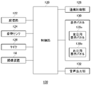
- FIG. 3 shows the functional blocks of the HMD 100.
- the control unit 120 is a main processor that processes and outputs various data such as image data, audio data, sensor data, and commands.
- Storage unit 122 temporarily stores data, instructions, and the like processed by control unit 120 .
- the orientation sensor 124 acquires sensor data regarding the movement of the HMD 100 .
- Attitude sensor 124 includes at least a three-axis acceleration sensor and a three-axis gyro sensor, and detects the value (sensor data) of each axis component at a predetermined cycle (for example, 1600 Hz).
- the communication control unit 128 transmits data output from the control unit 120 to the external information processing device 10 by wired or wireless communication via a network adapter or an antenna.
- the communication control unit 128 also receives data from the information processing device 10 and outputs the data to the control unit 120 .
- control unit 120 When the control unit 120 receives game image data and game sound data from the information processing device 10, the control unit 120 supplies the data to the display panel 130 for display, and also supplies the data to the sound output unit 132 for sound output.
- the display panel 130 includes a left-eye display panel 130a and a right-eye display panel 130b, and each display panel displays a pair of parallax images.
- the control unit 120 also causes the communication control unit 128 to transmit the sensor data acquired by the attitude sensor 124 , the audio data acquired by the microphone 126 , and the captured image acquired by the imaging device 14 to the information processing device 10 .
- FIG. 4 shows functional blocks of the information processing device 10 .
- the information processing device 10 includes a processing unit 200 and a communication unit 202 , and the processing unit 200 has an acquisition unit 210 , a setting unit 220 , an estimation processing unit 222 , a game execution unit 224 and an image generation unit 230 .
- the acquisition unit 210 includes a captured image acquisition unit 212, a sensor data acquisition unit 214, and an operation information acquisition unit 216.
- the image generation unit 230 includes an HMD image generation unit 232 that generates a display image to be displayed on the HMD 100, and an output device. and a TV image generation unit 234 for generating a display image to be displayed on the TV 15 .
- the communication unit 202 receives operation information transmitted from the input device 16 and supplies it to the acquisition unit 210 .
- the communication unit 202 also receives captured images and sensor data transmitted from the HMD 100 and supplies the received images to the acquisition unit 210 .
- the captured image acquisition unit 212 acquires an image of the surroundings of the HMD 100 and supplies it to the estimation processing unit 222 .
- the estimation processing unit 222 performs processing for estimating the position and orientation of the HMD 100 based on the captured image, and supplies position information and orientation information, which are estimation results, to the game execution unit 224 .
- the sensor data acquisition unit 214 acquires sensor data detected by the orientation sensor 124 of the HMD 100 and supplies the sensor data to the estimation processing unit 222 .
- the estimation processing unit 222 preferably uses sensor data to improve the estimation accuracy of the position information and orientation information of the HMD 100 .
- the user wearing the HMD 100 performs initial settings for capturing and registering his/her surrounding environment with the imaging device 14 .
- the user defines the area in which he or she will play (the area in which the user can move) to ensure safety during play.
- the information processing device 10 warns the user that the user is about to leave the play area.
- the imagery of the surrounding environment registered at initialization may be periodically updated to create an up-to-date map of the environment.
- the estimation processing unit 222 acquires images captured by the imaging device 14 of the HMD 100 in time series, divides each image into a grid, and detects feature points for each section.
- the estimation processing unit 222 associates the feature points between the image captured at time (t ⁇ 1) and the image captured at time (t), and calculates the movement amount ( dx, dy).
- the estimation processing unit 222 may perform feature point tracking processing by performing block matching of feature points in a peripheral search while predicting the motion of the feature points.
- the estimation processing unit 222 may perform feature point tracking processing using a known method other than this method.
- the estimation processing unit 222 can highly accurately estimate the position and orientation of the HMD 100 by performing the tracking process with high accuracy.
- the position information and orientation information of the HMD 100 are supplied to the game execution unit 224 and used as inputs for the game.
- the operation information acquisition section 216 acquires operation information transmitted from the input device 16 and supplies it to the game execution section 224 .
- the game execution unit 224 executes a game program based on the operation information of the input device 16 and the position information and orientation information of the HMD 100 to perform arithmetic processing to move the game character in the virtual space.
- the image generator 230 includes a GPU (Graphics Processing Unit) that executes rendering processing and the like, and generates game images.
- the HMD image generation unit 232 generates a display image to be displayed on the display panel 130 of the HMD 100, and the TV image generation unit 234 generates a display image to be displayed on the output device 15.
- the information processing apparatus 10 includes a sound generation unit that generates game sound.
- FIG. 5 shows an example of a display image displayed on the display panel 130.
- the HMD image generator 232 generates a game image and supplies it to the display panel 130 of the HMD 100 .
- the display panel 130 has the left-eye display panel 130a and the right-eye display panel 130b, and the HMD image generation unit 232 generates the left-eye game image and the right-eye game image, It is supplied to the left-eye display panel 130a and the right-eye display panel 130b.
- Left-eye display panel 130a and right-eye display panel 130b each display a game image.
- the TV image generation unit 234 generates the same game image as the image generated by the HMD image generation unit 232 and supplies it to the output device 15 .
- the TV image generation unit 234 since the user wearing the HMD 100 does not see the game image displayed on the output device 15, the TV image generation unit 234 generates a different game image for another user, It may be supplied to the output device 15 .
- the screen size of the output device 15 is large and the distance between the user and the output device 15 is short. For example, the area of the output device 15 included in the image captured by the imaging device 14 is increased.
- the estimation processing unit 222 will extract many feature points from the game image displayed on the output device 15, and since it cannot be associated with the feature points extracted in the past, tracking loss may occur. becomes higher.
- FIG. 6(a) shows an example of an image taken by the imaging device 14c
- FIG. 6(b) shows an example of an image taken by the imaging device 14d. Since the image capturing device 14c and the image capturing device 14d constitute a stereo camera, the captured images of both are slightly shifted in the horizontal direction. As shown in FIG. 6, the captured image largely includes the game image displayed on the output device 15 .
- the proportion of the game image displayed on the output device 15 is very large. Since the game image changes from moment to moment, it becomes difficult for the estimation processing unit 222 to extract effective feature points from the captured image, and the estimation processing for the position and orientation of the HMD 100 may fail.
- the TV image generation unit 234 generates a display image including at least a part of a pattern that is a still image, and the estimation processing unit 222 can extract feature points effective for tracking. make it
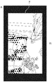
- FIG. 7 shows an example of an image displayed on the output device 15.
- the TV image generation unit 234 generates a display image partially including the pattern 70, which is a still image.
- the TV image generation unit 234 generates a display image including a pattern 70 forming a frame and a game video 72 inside the frame, and displays it on the output device 15 .
- the estimation processing unit 222 can extract feature points effective for tracking from the pattern 70 included in the image captured by the output device 15. becomes.
- the TV image generation unit 234 may display the game video 72 with a reduced image size inside the frame formed by the pattern 70, but the image size is not reduced and the rectangular frame formed by the pattern 70 is displayed. may be generated by superimposing on the game moving image 72 . It should be noted that the area occupied by the frame is preferably set to be 50% or less of the screen size of the output device 15 so as not to impair the visibility of the game moving image 72 . Note that the TV image generator 234 may display the pattern 70 as a block, for example, at four corners of the screen of the output device 15 instead of displaying it as a frame. That is, the TV image generator 234 may generate a display image including the pattern 70 as a block image in the corner.
- the TV image generation unit 234 generates a display image including the pattern 70 on one of the top, bottom, left, and right sides, or on a plurality of sides, so that the pattern 70 is positioned on either one of the top, bottom, left, or right of the screen of the output device 15. It may be displayed on one side, or on multiple sides. In either case, picture 70 is displayed as a still image to support the tracking process by estimation processor 222 .
- the TV image generator 234 does not have to include the game moving image 72 in the display image, and may generate a display image including, for example, the pattern 70, which is a still image, over the entire surface.
- the pattern 70 is preferably composed of a pattern that includes many corners. In order to improve tracking accuracy, the pattern 70 is preferably configured so as not to repeat the same pattern at close positions.
- the setting unit 220 sets ON or OFF of the picture display function by the TV image generation unit 234, and sets enable or disable of the function when the picture display function is set to ON.
- the TV image generation unit 234 When the setting unit 220 sets the pattern display function to be effective, the TV image generation unit 234 generates a display image including at least a part of the pattern 70 which is a still image, and displays it on the output device 15 .
- the setting unit 220 disables the picture display function, the TV image generation unit 234 does not generate a display image including the picture 70 .
- the setting unit 220 enables the pattern display function by the TV image generation unit 234 when the estimation processing unit 222 is performing the estimation processing of the position and orientation of the HMD 100, and when the estimation processing is not performed, the TV Invalidation of the pattern display function by the image generation unit 234 may be set. Therefore, when the estimation processing section 222 is performing estimation processing, the TV image generation section 234 generates a display image including the pattern 70 to support the tracking processing by the estimation processing section 222 . On the other hand, when the estimation processing unit 222 is not performing estimation processing, the TV image generation unit 234 does not generate a display image including the pattern 70 because there is no need to support the tracking processing by the estimation processing unit 222 . At this time, the TV image generator 234 may generate a display image including the game moving image 72 on the entire surface and display it on the output device 15 .
- the setting unit 220 enables the pattern display function by the TV image generation unit 234 when the user wears the HMD 100 on the head, and enables the TV image generation unit 234 when the user does not wear the HMD 100 on the head.
- the H.234 pattern display function may be disabled.
- the presence or absence of attachment is determined, for example, by the detection result of a proximity sensor (not shown) provided in HMD 100 . Therefore, when the user wears the HMD 100 on the head, the TV image generator 234 generates a display image including the pattern 70 to support the tracking processing by the estimation processor 222 .
- the TV image generation section 234 does not generate a display image including the pattern 70 because there is no need to support the tracking processing by the estimation processing section 222 .
- the TV image generator 234 may generate a display image including the game moving image 72 on the entire surface and display it on the output device 15 .
- the setting unit 220 performs pattern display by the TV image generation unit 234 on the condition that the estimation processing unit 222 has performed the estimation processing of the position and orientation of the HMD 100 and the user wears the HMD 100 on the head. You may set the enablement of the function.
- the estimation processing unit 222 When the estimation processing unit 222 recognizes the frame formed by the pattern 70 in the captured image, it may control the tracking process so as not to extract feature points from the game video 72 arranged inside the frame. Note that when the output device 15 displays a frame composed of the pattern 70 at the time of initial setting, and the image of the frame is registered, the estimation processing unit 222 calculates the feature point at the position of the frame during game play. You may control the tracking process so that it does not use
- FIG. 8 shows an example of an on/off setting screen for the pattern display function.
- This setting screen is displayed on the display panel 130 at the time of initial setting.
- the setting unit 220 performs the estimation processing on the condition that the estimation processing unit 222 is performing estimation processing of the position and orientation of the HMD 100 and the user is wearing the HMD 100 on the head.
- the pattern display function by the TV image generation unit 234 is enabled.
- the TV image generator 234 generates a display image including the pattern 70 .
- the setting unit 220 disables the pattern display function by the TV image generation unit 234 .
- the estimation processing unit 222 estimates the position and orientation of the HMD 100 by performing tracking processing using an image captured from the game image displayed on the entire surface of the output device 15. may fail.
- the setting unit 220 may automatically change the setting of the picture display function by the TV image generation unit 234 to ON to enable the picture display function.
- the HMD image generation unit 232 instead of the setting unit 220 automatically turning on the picture display function, the HMD image generation unit 232 generates a display image including options for enabling the picture display function and displays it on the display panel 130. you can
- FIG. 9 shows an example of a setting screen displayed on the display panel 130 during game play.
- the setting unit 220 changes the setting of the picture display function by the TV image generation unit 234 to ON, and enables the picture display function. This will improve the tracking accuracy.
- the present disclosure has been described above based on the examples. It should be understood by those skilled in the art that the above embodiments are examples, and that various modifications can be made to combinations of each component and each treatment process, and such modifications are also within the scope of the present disclosure. .
- the information processing apparatus 10 performs the estimation process in the embodiment, a part or all of the functions of the information processing apparatus 10 may be provided in the HMD 100 and the HMD 100 may perform the estimation process. At this time, the HMD 100 functions as an information processing device.
- the imaging device 14 is attached to the HMD 100 in the embodiment, the imaging device 14 may be attached to a position other than the HMD 100 as long as the space around the HMD 100 can be photographed.
- the setting unit 220 may dynamically set whether the pattern display function is enabled or disabled. For example, the setting unit 220 sets whether the pattern display function is enabled or disabled based on the distance between the output device 15 and the HMD 100 . Specifically, the setting unit 220 may enable the picture display function if the distance between the output device 15 and the HMD 100 is less than or equal to a predetermined length, and disable the picture display function if the distance is longer than the predetermined length.
- the setting unit 220 may set whether the pattern display function is enabled or disabled based on the ratio of the area occupied by the output device 15 included in the captured image. Specifically, the setting unit 220 enables the pattern display function when the ratio of the area occupied by the output device 15 is equal to or greater than a predetermined value, and disables the pattern display function when the ratio is less than the predetermined value. good.
- the screen size of the output device 15 and the distance between the output device 15 and the HMD 100 are detected.
- the user may be advised to set
- the screen size may be detected by HDMI (registered trademark). Whether the screen size is large and the distance is short may be determined based on the ratio of the area of the output device 15 included in the captured image of the imaging device 14 occupied.
- the setting unit 220 may select the pattern 70 to be displayed according to the screen size of the output device 15 . Specifically, if the screen size is small, the pattern 70 including a large pattern may be selected, and if the screen size is large, the pattern 70 including a small pattern may be selected. The setting unit 220 may select the pattern 70 based on the ratio of the area of the output device 15 included in the captured image.
- the present disclosure can be used in the technical field of generating display images.
Landscapes
- Engineering & Computer Science (AREA)
- Multimedia (AREA)
- Human Computer Interaction (AREA)
- General Engineering & Computer Science (AREA)
- Theoretical Computer Science (AREA)
- Physics & Mathematics (AREA)
- General Physics & Mathematics (AREA)
- Life Sciences & Earth Sciences (AREA)
- Health & Medical Sciences (AREA)
- Biophysics (AREA)
- Cardiology (AREA)
- General Health & Medical Sciences (AREA)
- Heart & Thoracic Surgery (AREA)
- User Interface Of Digital Computer (AREA)
- Controls And Circuits For Display Device (AREA)
- Position Input By Displaying (AREA)
Abstract
Priority Applications (1)
| Application Number | Priority Date | Filing Date | Title |
|---|---|---|---|
| EP22815813.5A EP4349432A1 (fr) | 2021-06-04 | 2022-05-13 | Dispositif de traitement d'informations et procédé de génération d'image |
Applications Claiming Priority (2)
| Application Number | Priority Date | Filing Date | Title |
|---|---|---|---|
| JP2021094484A JP2022186326A (ja) | 2021-06-04 | 2021-06-04 | 情報処理装置および画像生成方法 |
| JP2021-094484 | 2021-06-04 |
Publications (1)
| Publication Number | Publication Date |
|---|---|
| WO2022255058A1 true WO2022255058A1 (fr) | 2022-12-08 |
Family
ID=84324363
Family Applications (1)
| Application Number | Title | Priority Date | Filing Date |
|---|---|---|---|
| PCT/JP2022/020149 WO2022255058A1 (fr) | 2021-06-04 | 2022-05-13 | Dispositif de traitement d'informations et procédé de génération d'image |
Country Status (3)
| Country | Link |
|---|---|
| EP (1) | EP4349432A1 (fr) |
| JP (1) | JP2022186326A (fr) |
| WO (1) | WO2022255058A1 (fr) |
Citations (4)
| Publication number | Priority date | Publication date | Assignee | Title |
|---|---|---|---|---|
| JP2013535867A (ja) * | 2010-07-13 | 2013-09-12 | 株式会社ソニー・コンピュータエンタテインメント | モバイルデバイスに表示される補足ビデオコンテンツ |
| JP2015095045A (ja) | 2013-11-11 | 2015-05-18 | 株式会社ソニー・コンピュータエンタテインメント | 画像生成装置および画像生成方法 |
| JP2016048851A (ja) * | 2014-08-27 | 2016-04-07 | 日本電信電話株式会社 | マーカ埋め込み装置、マーカ検出装置、方法、及びプログラム |
| WO2020017327A1 (fr) * | 2018-07-17 | 2020-01-23 | ソニー株式会社 | Visiocasque et procédé de commande de visiocasque, dispositif de traitement d'informations, dispositif d'affichage, et programme |
-
2021
- 2021-06-04 JP JP2021094484A patent/JP2022186326A/ja active Pending
-
2022
- 2022-05-13 EP EP22815813.5A patent/EP4349432A1/fr active Pending
- 2022-05-13 WO PCT/JP2022/020149 patent/WO2022255058A1/fr active Application Filing
Patent Citations (4)
| Publication number | Priority date | Publication date | Assignee | Title |
|---|---|---|---|---|
| JP2013535867A (ja) * | 2010-07-13 | 2013-09-12 | 株式会社ソニー・コンピュータエンタテインメント | モバイルデバイスに表示される補足ビデオコンテンツ |
| JP2015095045A (ja) | 2013-11-11 | 2015-05-18 | 株式会社ソニー・コンピュータエンタテインメント | 画像生成装置および画像生成方法 |
| JP2016048851A (ja) * | 2014-08-27 | 2016-04-07 | 日本電信電話株式会社 | マーカ埋め込み装置、マーカ検出装置、方法、及びプログラム |
| WO2020017327A1 (fr) * | 2018-07-17 | 2020-01-23 | ソニー株式会社 | Visiocasque et procédé de commande de visiocasque, dispositif de traitement d'informations, dispositif d'affichage, et programme |
Also Published As
| Publication number | Publication date |
|---|---|
| EP4349432A1 (fr) | 2024-04-10 |
| JP2022186326A (ja) | 2022-12-15 |
Similar Documents
| Publication | Publication Date | Title |
|---|---|---|
| JP6511386B2 (ja) | 情報処理装置および画像生成方法 | |
| KR102502404B1 (ko) | 정보 처리 장치 및 방법, 그리고 프로그램 | |
| JP6845111B2 (ja) | 情報処理装置および画像表示方法 | |
| US10681276B2 (en) | Virtual reality video processing to compensate for movement of a camera during capture | |
| US11373379B2 (en) | Image generation apparatus and image generation method for generating augmented reality images based on user interaction | |
| JP6576536B2 (ja) | 情報処理装置 | |
| WO2019082794A1 (fr) | Dispositif, système et procédé de génération d'image et programme | |
| WO2019098198A1 (fr) | Dispositif, système et procédé de génération d'images, visiocasque et programme associé | |
| US11335071B2 (en) | Image generation apparatus and image generation method for augmented reality images based on object interaction | |
| WO2020129115A1 (fr) | Système de traitement d'informations, procédé de traitement d'informations et programme informatique | |
| JP6518645B2 (ja) | 情報処理装置および画像生成方法 | |
| US20240036327A1 (en) | Head-mounted display and image displaying method | |
| US11187895B2 (en) | Content generation apparatus and method | |
| JPWO2017199495A1 (ja) | 画像処理システム、画像処理装置、及びプログラム | |
| WO2022255058A1 (fr) | Dispositif de traitement d'informations et procédé de génération d'image | |
| JP2020530218A (ja) | 没入型視聴覚コンテンツを投影する方法 | |
| WO2019073925A1 (fr) | Dispositif de génération d'image et procédé de génération d'image | |
| WO2017163649A1 (fr) | Dispositif de traitement d'image | |
| JP6921204B2 (ja) | 情報処理装置および画像出力方法 | |
| US20240066394A1 (en) | Information processing apparatus and image generation method | |
| WO2024042929A1 (fr) | Dispositif de traitement d'informations et procédé de génération d'images | |
| US20240033618A1 (en) | Information processing apparatus and image generating method | |
| CN117452637A (zh) | 头戴式显示器和图像显示方法 |
Legal Events
| Date | Code | Title | Description |
|---|---|---|---|
| 121 | Ep: the epo has been informed by wipo that ep was designated in this application |
Ref document number: 22815813 Country of ref document: EP Kind code of ref document: A1 |
|
| WWE | Wipo information: entry into national phase |
Ref document number: 18560947 Country of ref document: US |
|
| WWE | Wipo information: entry into national phase |
Ref document number: 2022815813 Country of ref document: EP |
|
| NENP | Non-entry into the national phase |
Ref country code: DE |
|
| ENP | Entry into the national phase |
Ref document number: 2022815813 Country of ref document: EP Effective date: 20240104 |