WO2019097903A1 - Solid electrolyte composition, solid-electrolyte-containing sheet, all-solid-state secondary battery, production method for solid-electrolyte-containing sheet, and production method for all-solid-state secondary battery - Google Patents
Solid electrolyte composition, solid-electrolyte-containing sheet, all-solid-state secondary battery, production method for solid-electrolyte-containing sheet, and production method for all-solid-state secondary battery Download PDFInfo
- Publication number
- WO2019097903A1 WO2019097903A1 PCT/JP2018/037617 JP2018037617W WO2019097903A1 WO 2019097903 A1 WO2019097903 A1 WO 2019097903A1 JP 2018037617 W JP2018037617 W JP 2018037617W WO 2019097903 A1 WO2019097903 A1 WO 2019097903A1
- Authority
- WO
- WIPO (PCT)
- Prior art keywords
- solid electrolyte
- binder
- solid
- active material
- secondary battery
- Prior art date
Links
Images

Classifications
-
- H—ELECTRICITY
- H01—ELECTRIC ELEMENTS
- H01B—CABLES; CONDUCTORS; INSULATORS; SELECTION OF MATERIALS FOR THEIR CONDUCTIVE, INSULATING OR DIELECTRIC PROPERTIES
- H01B1/00—Conductors or conductive bodies characterised by the conductive materials; Selection of materials as conductors
- H01B1/06—Conductors or conductive bodies characterised by the conductive materials; Selection of materials as conductors mainly consisting of other non-metallic substances
- H01B1/10—Conductors or conductive bodies characterised by the conductive materials; Selection of materials as conductors mainly consisting of other non-metallic substances sulfides
-
- H—ELECTRICITY
- H01—ELECTRIC ELEMENTS
- H01B—CABLES; CONDUCTORS; INSULATORS; SELECTION OF MATERIALS FOR THEIR CONDUCTIVE, INSULATING OR DIELECTRIC PROPERTIES
- H01B1/00—Conductors or conductive bodies characterised by the conductive materials; Selection of materials as conductors
- H01B1/20—Conductive material dispersed in non-conductive organic material
-
- H—ELECTRICITY
- H01—ELECTRIC ELEMENTS
- H01B—CABLES; CONDUCTORS; INSULATORS; SELECTION OF MATERIALS FOR THEIR CONDUCTIVE, INSULATING OR DIELECTRIC PROPERTIES
- H01B13/00—Apparatus or processes specially adapted for manufacturing conductors or cables
-
- H—ELECTRICITY
- H01—ELECTRIC ELEMENTS
- H01B—CABLES; CONDUCTORS; INSULATORS; SELECTION OF MATERIALS FOR THEIR CONDUCTIVE, INSULATING OR DIELECTRIC PROPERTIES
- H01B5/00—Non-insulated conductors or conductive bodies characterised by their form
- H01B5/14—Non-insulated conductors or conductive bodies characterised by their form comprising conductive layers or films on insulating-supports
-
- H—ELECTRICITY
- H01—ELECTRIC ELEMENTS
- H01M—PROCESSES OR MEANS, e.g. BATTERIES, FOR THE DIRECT CONVERSION OF CHEMICAL ENERGY INTO ELECTRICAL ENERGY
- H01M10/00—Secondary cells; Manufacture thereof
- H01M10/05—Accumulators with non-aqueous electrolyte
- H01M10/052—Li-accumulators
- H01M10/0525—Rocking-chair batteries, i.e. batteries with lithium insertion or intercalation in both electrodes; Lithium-ion batteries
-
- H—ELECTRICITY
- H01—ELECTRIC ELEMENTS
- H01M—PROCESSES OR MEANS, e.g. BATTERIES, FOR THE DIRECT CONVERSION OF CHEMICAL ENERGY INTO ELECTRICAL ENERGY
- H01M10/00—Secondary cells; Manufacture thereof
- H01M10/05—Accumulators with non-aqueous electrolyte
- H01M10/056—Accumulators with non-aqueous electrolyte characterised by the materials used as electrolytes, e.g. mixed inorganic/organic electrolytes
- H01M10/0561—Accumulators with non-aqueous electrolyte characterised by the materials used as electrolytes, e.g. mixed inorganic/organic electrolytes the electrolyte being constituted of inorganic materials only
- H01M10/0562—Solid materials
-
- H—ELECTRICITY
- H01—ELECTRIC ELEMENTS
- H01M—PROCESSES OR MEANS, e.g. BATTERIES, FOR THE DIRECT CONVERSION OF CHEMICAL ENERGY INTO ELECTRICAL ENERGY
- H01M10/00—Secondary cells; Manufacture thereof
- H01M10/05—Accumulators with non-aqueous electrolyte
- H01M10/058—Construction or manufacture
- H01M10/0585—Construction or manufacture of accumulators having only flat construction elements, i.e. flat positive electrodes, flat negative electrodes and flat separators
-
- H—ELECTRICITY
- H01—ELECTRIC ELEMENTS
- H01M—PROCESSES OR MEANS, e.g. BATTERIES, FOR THE DIRECT CONVERSION OF CHEMICAL ENERGY INTO ELECTRICAL ENERGY
- H01M4/00—Electrodes
- H01M4/02—Electrodes composed of, or comprising, active material
- H01M4/13—Electrodes for accumulators with non-aqueous electrolyte, e.g. for lithium-accumulators; Processes of manufacture thereof
- H01M4/139—Processes of manufacture
-
- H—ELECTRICITY
- H01—ELECTRIC ELEMENTS
- H01M—PROCESSES OR MEANS, e.g. BATTERIES, FOR THE DIRECT CONVERSION OF CHEMICAL ENERGY INTO ELECTRICAL ENERGY
- H01M4/00—Electrodes
- H01M4/02—Electrodes composed of, or comprising, active material
- H01M4/62—Selection of inactive substances as ingredients for active masses, e.g. binders, fillers
-
- H—ELECTRICITY
- H01—ELECTRIC ELEMENTS
- H01M—PROCESSES OR MEANS, e.g. BATTERIES, FOR THE DIRECT CONVERSION OF CHEMICAL ENERGY INTO ELECTRICAL ENERGY
- H01M10/00—Secondary cells; Manufacture thereof
- H01M10/05—Accumulators with non-aqueous electrolyte
- H01M10/052—Li-accumulators
-
- H—ELECTRICITY
- H01—ELECTRIC ELEMENTS
- H01M—PROCESSES OR MEANS, e.g. BATTERIES, FOR THE DIRECT CONVERSION OF CHEMICAL ENERGY INTO ELECTRICAL ENERGY
- H01M2300/00—Electrolytes
- H01M2300/0017—Non-aqueous electrolytes
- H01M2300/0065—Solid electrolytes
- H01M2300/0068—Solid electrolytes inorganic
-
- H—ELECTRICITY
- H01—ELECTRIC ELEMENTS
- H01M—PROCESSES OR MEANS, e.g. BATTERIES, FOR THE DIRECT CONVERSION OF CHEMICAL ENERGY INTO ELECTRICAL ENERGY
- H01M2300/00—Electrolytes
- H01M2300/0088—Composites
- H01M2300/0091—Composites in the form of mixtures
-
- Y—GENERAL TAGGING OF NEW TECHNOLOGICAL DEVELOPMENTS; GENERAL TAGGING OF CROSS-SECTIONAL TECHNOLOGIES SPANNING OVER SEVERAL SECTIONS OF THE IPC; TECHNICAL SUBJECTS COVERED BY FORMER USPC CROSS-REFERENCE ART COLLECTIONS [XRACs] AND DIGESTS
- Y02—TECHNOLOGIES OR APPLICATIONS FOR MITIGATION OR ADAPTATION AGAINST CLIMATE CHANGE
- Y02E—REDUCTION OF GREENHOUSE GAS [GHG] EMISSIONS, RELATED TO ENERGY GENERATION, TRANSMISSION OR DISTRIBUTION
- Y02E60/00—Enabling technologies; Technologies with a potential or indirect contribution to GHG emissions mitigation
- Y02E60/10—Energy storage using batteries
-
- Y—GENERAL TAGGING OF NEW TECHNOLOGICAL DEVELOPMENTS; GENERAL TAGGING OF CROSS-SECTIONAL TECHNOLOGIES SPANNING OVER SEVERAL SECTIONS OF THE IPC; TECHNICAL SUBJECTS COVERED BY FORMER USPC CROSS-REFERENCE ART COLLECTIONS [XRACs] AND DIGESTS
- Y02—TECHNOLOGIES OR APPLICATIONS FOR MITIGATION OR ADAPTATION AGAINST CLIMATE CHANGE
- Y02P—CLIMATE CHANGE MITIGATION TECHNOLOGIES IN THE PRODUCTION OR PROCESSING OF GOODS
- Y02P70/00—Climate change mitigation technologies in the production process for final industrial or consumer products
- Y02P70/50—Manufacturing or production processes characterised by the final manufactured product
Definitions
- the present invention relates to a solid electrolyte composition, a solid electrolyte-containing sheet and an all solid secondary battery, and a method of manufacturing a solid electrolyte containing sheet and an all solid secondary battery.
- a lithium ion secondary battery is a storage battery that has a negative electrode, a positive electrode, and an electrolyte sandwiched between the negative electrode and the positive electrode, and enables charge and discharge by reciprocating lithium ions between the two electrodes.
- organic electrolytes have been used as electrolytes.
- the organic electrolyte is liable to leak, and a short circuit may occur inside the battery due to overcharge or overdischarge, which may cause ignition, and further improvement of safety and reliability is required. Under such circumstances, an all solid secondary battery using an inorganic solid electrolyte in place of the organic electrolyte has attracted attention.
- the all solid secondary battery all of the negative electrode, the electrolyte and the positive electrode are solid, which can greatly improve the safety and reliability issues in batteries using organic electrolytes, and can also extend the life. It will be. Furthermore, the all solid secondary battery can have a laminated structure in which the electrode and the electrolyte are directly arranged in series. Therefore, energy density can be increased as compared with a secondary battery using an organic electrolytic solution, and application to an electric car or a large storage battery is expected.
- the present invention is a solid electrolyte composition containing an inorganic solid electrolyte, a binder, and a dispersion medium, and by forming a layer using this composition, it becomes possible to form a layer with a more uniform thickness.
- Another object of the present invention is to provide a solid electrolyte composition in which this layer exhibits excellent ion conductivity.
- the present invention can realize a solid electrolyte-containing sheet which can realize a more uniform layer thickness and exhibits excellent ion conductivity, an electrode sheet for an all solid secondary battery, an all solid secondary battery, and a method for producing them The task is to provide.
- the present inventors diligently studied in view of the above problems.
- the solid electrolyte composition used to form the solid electrolyte layer and the electrode active material layer constituting the all solid secondary battery in addition to the particulate polymer as a binder, in the dispersion medium of the composition,
- a specific amount of a polymer having physical properties present in the supernatant without being precipitated a polymer which is soluble in the dispersion medium of the composition or which is in the form of fine particles of a very small particle diameter in this dispersion medium.
- a solid electrolyte composition comprising an inorganic solid electrolyte (A) having conductivity of an ion of a metal belonging to Periodic Table Group 1 or Group 2, a binder (B), and a dispersion medium (C),
- the binder (B) is added to the first binder (B1) which precipitates when it is subjected to centrifugation at a temperature of 25 ° C.
- a solid electrolyte-containing sheet comprising an inorganic solid electrolyte (A) having conductivity of an ion of a metal belonging to periodic group 1 group or group 2, a binder (B), and a solvent (C1),
- the binder (B) is subjected to the above-mentioned centrifugal separation treatment with the first binder (B1) which precipitates when it is subjected to a centrifugal treatment of 1 hour at a temperature of 25 ° C. and a centrifugal force of 610,000 G in the solvent (C1).
- a solid electrolyte containing sheet wherein a content X of the first binder (B1) and a content Y of the second binder (B2) satisfy the following formula on a mass basis. 0.01 ⁇ Y / (X + Y) ⁇ 0.10 [12]
- An all solid secondary battery including a positive electrode active material layer, a negative electrode active material layer, and a solid electrolyte layer between the positive electrode active material layer and the negative electrode active material layer,
- the all-solid-state secondary battery by which at least 1 layer of the said positive electrode active material layer, the said negative electrode active material layer, and the said solid electrolyte layer was comprised with the solid electrolyte content sheet of [10] or [11] description.
- a method for producing a solid electrolyte-containing sheet comprising the steps of applying the solid electrolyte composition according to any one of [1] to [9] on a substrate to form a coated film.
- the solid electrolyte composition of the present invention contains an inorganic solid electrolyte, a binder of a specific composition, and a dispersion medium, and when used as a layer forming material of an all solid secondary battery, layer formation with a more uniform thickness is achieved Also, this layer exhibits excellent ionic conductivity.
- the solid electrolyte-containing sheet, the electrode sheet for an all solid secondary battery, and the all solid secondary battery of the present invention can realize a more uniform layer thickness and exhibit excellent ion conductivity. According to the solid electrolyte containing sheet of the present invention and the manufacturing method of the all solid secondary battery, the solid electrolyte containing sheet of the present invention mentioned above and the all solid secondary battery can be obtained.
- FIG. 1 is a longitudinal sectional view schematically showing an all solid secondary battery according to a preferred embodiment of the present invention.
- FIG. 2 is a longitudinal cross-sectional view which shows typically the all-solid-state secondary battery (coin battery) produced in the Example.
- a numerical range represented using “to” means a range including numerical values described before and after “to” as the lower limit value and the upper limit value.
- the solid electrolyte composition of the present invention includes an inorganic solid electrolyte having conductivity of an ion of a metal belonging to Periodic Table Group 1 or Group 2, a binder (B), and a dispersion medium (C).
- the binder (B) contains, in a specific ratio, those which precipitate when subjected to ultracentrifugation treatment in the state of being contained in the dispersion medium (C) and those which do not precipitate (those which remain in the supernatant).
- the binder (B) disperses or dissolves the binder (B) in the dispersion medium (C) and is subjected to centrifugal treatment (ultracentrifugal treatment) at a temperature of 25 ° C. and a centrifugal force of 610000 G for 1 hour, It contains a binder having a physical property to precipitate (first binder (B1)) and a binder having a physical property remaining in the supernatant without sedimentation (second binder (B2)).
- first binder (B1) a binder having a physical property to precipitate
- second binder (B2) a binder having a physical property remaining in the supernatant without sedimentation
- the relationship between the content X of the first binder (B1) and the content Y of the second binder (B2) satisfies the following formula on a mass basis.
- the solid electrolyte composition of the present invention can optionally contain an active material (D) described later. Moreover, the conductive support agent (E) may be included. The solid electrolyte composition containing these can be made into the formation material of an electrode active material layer.
- the solid electrolyte composition of the present invention is not particularly limited in the state of mixing with each component, as long as each component specified in the present invention is included.
- the solid electrolyte composition of the present invention is preferably in a state in which each component is substantially uniformly dispersed in the dispersion medium at least before or at the time of use.
- the binder (B) has the above-described constitution, and by forming a layer using this composition, it is possible to form a layer having a more uniform thickness. In addition, this layer is also excellent in ion conductivity.
- the inorganic solid electrolyte is an inorganic solid electrolyte
- the solid electrolyte is a solid electrolyte capable of transferring ions inside thereof.
- An organic solid electrolyte a polymer electrolyte represented by polyethylene oxide (PEO) or the like, an organic electrolyte represented by lithium bis (trifluoromethanesulfonyl) imide (LiTFSI) or the like because it does not contain an organic substance as a main ion conductive material It is clearly distinguished from electrolyte salt).
- the inorganic solid electrolyte is solid in a steady state, it is not usually dissociated or released into cations and anions. In this respect, it is also clearly distinguished from the electrolyte solution or the inorganic electrolyte salt (LiPF 6 , LiBF 4 , LiFSI, LiCl, etc.) in which the cation and the anion are dissociated or released in the polymer.
- the inorganic solid electrolyte is not particularly limited as long as it has ion conductivity of a metal belonging to Periodic Table Group 1 or Group 2, and one having no electron conductivity is common.
- the inorganic solid electrolyte has ion conductivity of a metal belonging to Group 1 or Group 2 of the periodic table.
- An inorganic solid electrolyte can be used by appropriately selecting a solid electrolyte material to be applied to this type of product.
- As the inorganic solid electrolyte (i) a sulfide-based inorganic solid electrolyte and (ii) an oxide-based inorganic solid electrolyte are mentioned as representative examples, and in view of high ion conductivity and ease of interparticle interface bonding, sulfide Inorganic solid electrolytes are preferred.
- the inorganic solid electrolyte preferably has an ion conductivity of lithium ion.
- a sulfide-based inorganic solid electrolyte contains a sulfur atom (S) and has ion conductivity of a metal belonging to Periodic Table 1 Group or Group 2 and And compounds having electron insulating properties are preferred.
- the sulfide-based inorganic solid electrolyte contains at least Li, S and P as elements and preferably has lithium ion conductivity, but depending on the purpose or case, other than Li, S and P. It may contain an element.
- L represents an element selected from Li, Na and K, and Li is preferred.
- M represents an element selected from B, Zn, Sn, Si, Cu, Ga, Sb, Al and Ge.
- A represents an element selected from I, Br, Cl and F.
- a1 to e1 represent composition ratios of respective elements, and a1: b1: c1: d1: e1 satisfies 1 to 12: 0 to 5: 1: 2 to 12: 0 to 10. 1 to 9 is preferable, and 1.5 to 7.5 is more preferable. 0 to 3 is preferable, and 0 to 1 is more preferable as b1. 2.5 to 10 are preferable and 3.0 to 8.5 of d1 are more preferable. 0 to 5 is preferable, and 0 to 3 is more preferable as e1.
- composition ratio of each element can be controlled by adjusting the compounding ratio of the raw material compound at the time of producing the sulfide-based inorganic solid electrolyte as described below.
- the sulfide-based inorganic solid electrolyte may be non-crystalline (glass) or crystallized (glass-ceramicized), or only part of it may be crystallized.
- a Li—P—S-based glass containing Li, P and S, or a Li—P—S-based glass ceramic containing Li, P and S can be used.
- the sulfide-based inorganic solid electrolyte includes, for example, lithium sulfide (Li 2 S), phosphorus sulfide (for example, diphosphorus pentasulfide (P 2 S 5 )), single phosphorus, single sulfur, sodium sulfide, hydrogen sulfide, lithium halide (for example, It can be produced by the reaction of at least two or more of LiI, LiBr, LiCl) and sulfides of elements represented by the above M (eg, SiS 2 , SnS, GeS 2 ).
- Li 2 S lithium sulfide
- phosphorus sulfide for example, diphosphorus pentasulfide (P 2 S 5 )
- single phosphorus single sulfur
- sodium sulfide sodium sulfide
- hydrogen sulfide lithium halide
- Li halide for example, It can be produced by the reaction of at least two or more of LiI, LiBr,
- the ratio of Li 2 S to P 2 S 5 in the Li-P-S-based glass and Li-P-S-based glass ceramic is preferably a molar ratio of Li 2 S: P 2 S 5 of 60:40 to 90:10, more preferably 68:32 to 78:22.
- a sulfide-based inorganic solid electrolyte having high lithium ion conductivity can be obtained by mixing the ratio of Li 2 S and P 2 S 5 in this range.
- the lithium ion conductivity can be preferably 1 ⁇ 10 ⁇ 4 S / cm or more, more preferably 1 ⁇ 10 ⁇ 3 S / cm or more. There is no particular upper limit, but it is practical to be 1 ⁇ 10 ⁇ 1 S / cm or less.
- Li 2 S-P 2 S 5 Li 2 S-P 2 S 5 -LiCl, Li 2 S-P 2 S 5 -H 2 S, Li 2 S-P 2 S 5 -H 2 S-LiCl, Li 2 S-LiI-P 2 S 5 , Li 2 S-LiI-Li 2 O-P 2 S 5 , Li 2 S-LiBr-P 2 S 5 , Li 2 S-Li 2 O-P 2 S 5 , Li 2 S-Li 3 PO 4 -P 2 S 5 , Li 2 S-P 2 S 5- P 2 O 5 , Li 2 S-P 2 S 5- SiS 2 , Li 2 S-P 2 S 5- SiS 2 -LiCl, Li 2 S-P 2 S 5 -SnS, Li 2 S-P 2 S 5 -Al 2 S 3, Li 2 S-GeS 2, Li 2 S-GeS 2, Li 2 S-
- the mixing ratio of each raw material does not matter.
- an amorphization method can be mentioned.
- the amorphization method for example, a mechanical milling method, a solution method and a melt quenching method can be mentioned. According to these amorphization methods, processing at normal temperature becomes possible, and the manufacturing process can be simplified.
- the oxide-based inorganic solid electrolyte contains an oxygen atom (O) and has ion conductivity of a metal belonging to Periodic Table List 1 or 2 and And compounds having electron insulating properties are preferred.
- Li xa La ya TiO 3 (0.3 ⁇ xa ⁇ 0.7, 0.3 ⁇ ya ⁇ 0.7) (LLT)
- Mbb is at least one or more elements of Al, Mg, Ca, Sr, V, Nb, Ta, Ti, Ge, In, and Sn, and 5 ⁇ xb ⁇ 10, 1 ⁇ yb ⁇ 4, 1 ⁇ zb ⁇ 4, 0 ⁇ mb ⁇ 2, 5 ⁇ nb ⁇ 20)
- Li x c B y c M cc z c O nc (M cc is at least one or more of C, S, Al, Si, Ga, Ge, In, and Sn Of 0 ⁇ xc ⁇ 5, 0 ⁇ yc ⁇ 1, 0 ⁇ zc ⁇ 1, 0 ⁇ nc ⁇ 6), Li
- D ee is a halogen atom or two types Represents a combination of the above halogen atoms), Li xf Si yf O zf (1 ⁇ xf ⁇ 5, 0 ⁇ yf ⁇ 3, 1 ⁇ zf ⁇ 10), Li xg S yg O zg (1 ⁇ xg ⁇ 3, 0 ⁇ yg ⁇ 2, 1 ⁇ zg ⁇ 10), Li 3 BO 3 -Li 2 SO 4 , Li 2 O-B 2 O 3 -P 2 O 5 , Li 2 O-SiO 2 , Li 6 BaLa 2 Ta 2 O 12 , Li 3 PO (4-3 / 2 w) N w (w ⁇ 1), Li 3.5 Zn 0.25 GeO 4 having LISICON (Lithium superionic conductor) type crystal structure, having perovskite type crystal structure L 0.55 Li 0.35 TiO 3, NASICON LiTi 2 P 3 O 12 having a (Natrium super ionic conductor)
- Li, P and O phosphorus compounds containing Li, P and O.
- Li 3 PO 4 lithium phosphate
- LiPON in which part of oxygen of lithium phosphate is replaced with nitrogen
- LiPOD 1 LiPOD 1
- LiA 1 ON LiA 1 is at least one selected from Si, B, Ge, Al, C, Ga, etc.
- the inorganic solid electrolyte is preferably in the form of particles.
- the particle size of the inorganic solid electrolyte is not particularly limited.
- the particle diameter of the inorganic solid electrolyte is preferably 0.01 ⁇ m or more, more preferably 0.2 ⁇ m or more, and still more preferably 0.3 ⁇ m or more, in terms of ion conductivity, further processability and interface formation.
- the particle size of the inorganic solid electrolyte is preferably 100 ⁇ m or less, more preferably 50 ⁇ m or less, still more preferably 20 ⁇ m or less, still more preferably 4 ⁇ m or less, and particularly preferably 2 ⁇ m or less.
- the particle size of the inorganic solid electrolyte particles means the average particle size and can be determined as follows.
- the inorganic solid electrolyte particles are diluted with water (heptane for water labile substances) in a 20 mL sample bottle to dilute the 1 wt% dispersion.
- the diluted dispersed sample is irradiated with 1 kHz ultrasound for 10 minutes, and used immediately thereafter for the test.
- a laser diffraction / scattering particle size distribution analyzer LA-920 (trade name, manufactured by HORIBA)
- data acquisition is performed 50 times using a quartz cell for measurement at a temperature of 25 ° C.
- JIS Z 8828 2013 "Particle diameter analysis-dynamic light scattering method" as necessary. Make five samples per level and adopt the average value.
- the inorganic solid electrolyte may be used singly or in combination of two or more.
- the content of the inorganic solid electrolyte in the solid electrolyte composition is not particularly limited.
- the inorganic solid electrolyte is at least 5 parts by mass in 100 parts by mass of the solid component in the composition, taking into consideration the reduction of the interface resistance and the maintenance of the reduced interface resistance when used in an all solid secondary battery
- the amount is preferably 10 parts by mass or more, and more preferably 20 parts by mass or more.
- the inorganic solid electrolyte is preferably 99.9 parts by mass or less, more preferably 99.5 parts by mass or less, and 99 parts by mass or less in 100 parts by mass of the solid components in the composition. Is particularly preferred.
- the solid content refers to a component which does not evaporate or evaporate when the solid electrolyte composition is dried at 120 ° C. under a nitrogen atmosphere for 6 hours under a pressure of 1 mmHg. Typically, it refers to components other than the dispersion medium described later.
- the solid electrolyte composition of the present invention contains a binder (B).
- the binder (B) contained in the composition can be composed of various polymers.
- the binder (B) may contain particulates or non-particulates.
- the solid electrolyte composition of the present invention contains, at a specific ratio, physical properties to be precipitated components and physical properties to be supernatant components in the ultracentrifugation treatment under specific conditions.
- the binder (B) can be made of, for example, an organic resin described below.
- fluorinated resin examples include polytetrafluoroethylene (PTFE), polyvinylidene fluoride (PVdF), and a copolymer of polyvinylidene fluoride and hexafluoropropylene (PVdF-HFP).
- PTFE polytetrafluoroethylene
- PVdF polyvinylidene fluoride
- PVdF-HFP a copolymer of polyvinylidene fluoride and hexafluoropropylene
- hydrocarbon-based thermoplastic resin examples include polyethylene, polypropylene, styrene butadiene rubber (SBR), hydrogenated styrene butadiene rubber (HSBR), butylene rubber, acrylonitrile butadiene rubber, polybutadiene, and polyisoprene.
- ((Meth) acrylic resin) examples include various (meth) acrylic monomers, (meth) acrylamide monomers, and copolymers of two or more of these monomers.
- copolymers (copolymers) with other vinyl monomers are also suitably used. Examples include copolymers of methyl (meth) acrylate and styrene, copolymers of methyl (meth) acrylate and acrylonitrile, and copolymers of butyl (meth) acrylate, acrylonitrile and styrene. It is not limited to these.
- the copolymer may be either a statistical copolymer or a periodic copolymer, with random copolymers being preferred.
- polyester resin examples include polyurethane resin, polyurea resin, polyamide resin, polyimide resin, polyester resin, polyether resin, polycarbonate resin, and cellulose derivative resin.
- fluorine-containing resins hydrocarbon-based thermoplastic resins, (meth) acrylic resins, polyurethane resins, polycarbonate resins and cellulose derivative resins are preferable, and they have good affinity with inorganic solid electrolytes, and resins themselves
- a (meth) acrylic resin or a polyurethane resin is particularly preferred in that it has good flexibility and can exhibit stronger binding to solid particles.
- a commercial item can be used for said various resin.
- it can also prepare by a conventional method.
- the organic resin demonstrated above is an example, and the binder (B) in this invention is not limited to these forms.
- the weight average molecular weight of a polymer refers to a weight average molecular weight in terms of standard polystyrene by gel permeation chromatography (GPC) unless otherwise specified.
- the measured value is a value measured under the following conditions. However, depending on the type of polymer, an appropriate eluent can be selected and used. (conditions) Columns: TOSOH TSKgel Super HZM-H (trade name), TOSOH TSKgel Super HZ 4000 (trade name), and TOSOH TSKgel Super HZ 2000 (trade name) are used together.
- Carrier Tetrahydrofuran Measurement temperature: 40 ° C
- Carrier flow rate 1.0 mL / min
- Sample concentration 0.1% by mass
- Detector RI (refractive index) detector
- the binder (B) contained in the solid electrolyte composition of the present invention is dispersed in the below-described dispersion medium constituting the solid electrolyte composition (partly may be dissolved) at a temperature of 25 ° C.
- the content of the binder in the dispersion medium is 0.1 to 10% by mass. Within this content range, even if the content of the binder is varied, the phenomenon that the precipitate component is present in the supernatant or the supernatant component is the precipitate component is in fact It does not occur above. Moreover, in determination of the physical property of the binder based on an ultracentrifugation process, in a dispersion medium, it shall carry out in the state to which only the binder was disperse
- the relationship between the content X of the first binder (B1) and the content Y of the second binder (B2) satisfies the following formula on a mass basis. 0.01 ⁇ Y / (X + Y) ⁇ 0.10 That is, in the polymer constituting the binder (B) contained in the solid electrolyte composition, the proportion of the polymer having physical properties present in the supernatant without sedimentation in the ultracentrifugation treatment is 1 mass% or more and less than 10 mass% is there.
- the polymer constituting the binder (B) the polymer having the physical properties of being dissolved in the dispersion medium even by the ultracentrifugation treatment and / or existing in the dispersion medium as resin fine particles of extremely small particle diameter
- the ratio of is 1% by mass or more and less than 10% by mass.
- the first binder (B1) is usually present as fine resin particles in the dispersion medium.
- the first binder (B1) and the second binder (B2) may be present independently or in an interactive (adsorbed etc.) state. It is also good.
- the relationship between the content X of the first binder (B1) and the content Y of the second binder (B2) preferably satisfies the following formula on a mass basis, 0.015 ⁇ Y / (X + Y) ⁇ 0.09 It is more preferable to satisfy the following formula, 0.02 ⁇ Y / (X + Y) ⁇ 0.08 It is more preferable to satisfy the following formula. 0.025 ⁇ Y / (X + Y) ⁇ 0.075
- the binder when the binder is in a state of being dissolved in the dispersion medium, the binder covers almost the entire solid particle surface in the layer formed using the binder. This state can enhance the binding between solid particles, but usually the interface resistance increases and the ion conductivity decreases. Therefore, as described in, for example, JP-A-2015-088486, a binder is made to be present in the form of particles using a resin that does not dissolve in the dispersion medium, and the binding property between solid particles is enhanced in the formed layer. There are reports of techniques to suppress the increase in interface resistance.
- the solid electrolyte composition of the present invention it is added to the first binder (B1) which is hardly soluble in the dispersion medium and becomes a sedimentation component by the ultracentrifugation treatment, and dissolved in the dispersion medium or A specific amount of a second binder (B2) which is present and becomes a supernatant component by ultracentrifugation treatment is contained.
- the concept is different from the technology in which only the fine particle polymer is used as the binder.
- the increase in interface resistance can be effectively suppressed and the ion conductivity becomes excellent.
- the layer formed using this solid electrolyte composition has a more uniform thickness throughout.
- the first binder (B1) may partially cover the surface of the solid particle without covering it, thereby enhancing the binding property between the solid particles without causing a decrease in ion conductivity.
- the second binder (B2) acts as a dispersant for solid particles and acts in a complex manner to suppress the aggregation of the solid particles in the slurry.
- the first binder (B1) exhibits the above behavior by ultracentrifugation treatment.
- the first binder (B1) is usually in the form of particles.
- the particle diameter of the first binder (B1) is preferably 10 to 10000 nm, more preferably 50 to 1000 nm, and still more preferably 100 to 500 nm.
- the particle size of the binder particles means the average particle size of primary particles.
- the measurement of the average particle size of the binder particles can be determined in the same manner as the particle size of the inorganic solid electrolyte.
- the binder resin particles are dried if necessary, and then the particle size is measured by transmission electron microscope (TEM) observation.
- TEM transmission electron microscope
- the number average molecular weight of the polymer constituting the first binder (B1) is preferably 10,000 to 1,000,000, and more preferably 30,000 to 500,000, from the viewpoint of improving the binding property between solid particles. It is also preferable that the first binder (B1) is a crosslinked product of a polymer having a weight average molecular weight in the above range.
- the second binder (B2) exhibits the above behavior by ultracentrifugation treatment.
- the second binder (B2) is a polymer that is soluble in the dispersion medium that constitutes the composition, or is present as particles with a very small particle diameter in the dispersion medium that constitutes the composition.
- the second binder (B2) may be present in a state of interaction (adsorption, etc.) with the first binder (B1).
- the number average molecular weight of the polymer constituting the second binder (B2) is preferably 1000 to 100000, and more preferably 3000 to 50000, from the viewpoint of improving the adsorption rate to the solid particles.
- the polymer which comprises a binder (B) contains the polymer containing the component which has a polyalkylene oxide chain from a viewpoint of the improvement of the adsorption amount with respect to solid particle
- the binder (B) contains a polymer containing a component having a nitrile group (cyano group), from the viewpoint of suppressing the swelling of the latex particles with respect to the coating solvent due to the improvement of cohesive force Is also preferred.
- the total content of the first binder (B1) and the second binder (B2) is the reduction in interface resistance and the reduction in interface resistance when used in an all solid secondary battery.
- 0.01 mass part or more is preferable in 100 mass parts of solid components, 0.1 mass part or more is more preferable, and 1 mass part or more is still more preferable. Further, from the viewpoint of battery performance, 20 parts by mass or less is preferable, 10 parts by mass or less is more preferable, and 5 parts by mass or less is still more preferable.
- the weight of binder resin particles] is preferably in the range of 1000 to 1, more preferably 500 to 2, and still more preferably 100 to 10.
- the binder (B) contained in the solid electrolyte composition of the present invention may be composed of one kind of polymer having the same kind of constituent component and constituent component ratio, but in that case, one having a wide molecular weight distribution is used For example, the polymer is separated into a precipitated component and a supernatant component by ultracentrifugation treatment.
- the binder (B) usually contains two or more kinds of polymers having different constituents (including different constituent ratios of the constituents) from one another.
- the binder (B) preferably contains 2 to 10 polymers having different constituents, more preferably 2 to 5 polymers having different constituents, and 2 to 4 polymers having different constituents. It is further preferred that the polymer of
- the solid electrolyte composition of the present invention may contain an active material capable of inserting and releasing ions of a metal element belonging to Group 1 or Group 2 of the periodic table.
- the active material includes a positive electrode active material and a negative electrode active material.
- the solid electrolyte composition containing an active material can be used suitably for formation of the electrode active material layer of an all-solid-state secondary battery.
- the shape of the active material is not particularly limited, but is preferably in the form of particles. Further, the particle size of the active material is not particularly limited as long as the above particle size ratio is satisfied.
- the particle diameter of the active material is preferably 0.1 ⁇ m or more, more preferably 1 ⁇ m or more, and 2 ⁇ m or more, from the viewpoint of improving dispersibility, improving contact area between solid particles, and reducing interfacial reactivity. Is more preferred. Moreover, 20 micrometers or less are preferable, as for the particle size of an active material, 10 micrometers or less are more preferable, and 5 micrometers or less are more preferable.
- the particle size of the active material means the average particle size and can be determined in the same manner as the particle size of the inorganic solid electrolyte. If the particle size of the active material is equal to or less than the measurement limit of the particle size measuring apparatus, the active material is dried as needed, and then the particle size is measured by transmission electron microscope (TEM) observation.
- TEM transmission electron microscope
- the active material includes a positive electrode active material and a negative electrode active material, and is a metal oxide (preferably a transition metal oxide) which is a positive electrode active material, or a metal oxide which is a negative electrode active material or Sn, Si, Al and Metals capable of alloying with lithium such as In are preferred.
- a solid electrolyte composition containing an active material positive electrode active material or negative electrode active material
- a composition for an electrode composition for positive electrode or a composition for negative electrode.
- the positive electrode active material is preferably one capable of reversibly inserting and releasing lithium ions.
- the material is not particularly limited as long as it has the above-described characteristics, and may be a transition metal oxide, an organic substance, an element capable of being complexed with Li such as sulfur, a complex of sulfur and a metal, or the like. Among them, it is preferable to use a transition metal oxide as the positive electrode active material, and a transition metal oxide having a transition metal element M a (one or more elements selected from Co, Ni, Fe, Mn, Cu and V) Are more preferred.
- an element M b (an element of Group 1 (Ia) other than lithium, an element of Group 1 (Ia) of the metal periodic table, an element of Group 2 (IIa), Al, Ga, In, Ge, Sn, Pb, Elements such as Sb, Bi, Si, P or B may be mixed.
- the mixing amount of M b is preferably 0 to 30 mol% with respect to the amount (100 mol%) of the transition metal element M a . It is more preferable to be synthesized by mixing so that the molar ratio of Li / M a is 0.3 to 2.2.
- transition metal oxide examples include a transition metal oxide having a (MA) layered rock salt type structure, a transition metal oxide having a (MB) spinel type structure, a (MC) lithium-containing transition metal phosphate compound, (MD And the like) lithium-containing transition metal halogenated phosphoric acid compounds and (ME) lithium-containing transition metal silicate compounds.
- MA transition metal oxide having a
- MB transition metal oxide having a (MB) spinel type structure
- MC lithium-containing transition metal phosphate compound
- MD And the like lithium-containing transition metal halogenated phosphoric acid compounds
- ME lithium-containing transition metal silicate compounds.
- transition metal oxides having a layered rock salt type structure LiCoO 2 (lithium cobaltate [LCO]), LiNi 2 O 2 (lithium nickelate), LiNi 0.85 Co 0.10 Al 0. 05 O 2 (lithium nickel cobalt aluminate [NCA]), LiNi 1/3 Co 1/3 Mn 1/3 O 2 (lithium nickel manganese cobaltate [NMC]) and LiNi 0.5 Mn 0.5 O 2 ( And lithium manganese nickelate).
- LiCoO 2 lithium cobaltate [LCO]
- LiNi 2 O 2 lithium nickelate
- LiNi 0.85 Co 0.10 Al 0. 05 O 2 lithium nickel cobalt aluminate [NCA]
- LiNi 1/3 Co 1/3 Mn 1/3 O 2 lithium nickel manganese cobaltate [NMC]
- LiNi 0.5 Mn 0.5 O 2 And lithium manganese nickelate
- transition metal oxide having a (MB) spinel structure examples include LiMn 2 O 4 (LMO), LiCoMnO 4 , Li 2 FeMn 3 O 8 , Li 2 CuMn 3 O 8 , Li 2 CrMn 3 O 8 and Li 2 NiMn 3 O 8 and the like.
- (MC) lithium-containing transition metal phosphate compounds include olivine-type iron phosphates such as LiFePO 4 and Li 3 Fe 2 (PO 4 ) 3 , iron pyrophosphates such as LiFeP 2 O 7 , LiCoPO 4 etc. Cobalt phosphates and monoclinic Nasacon type vanadium phosphate salts such as Li 3 V 2 (PO 4 ) 3 (lithium vanadium phosphate).
- (MD) as the lithium-containing transition metal halogenated phosphate compound for example, Li 2 FePO 4 F such fluorinated phosphorus iron salt, Li 2 MnPO 4 hexafluorophosphate manganese salts such as F and Li 2 CoPO 4 F And cobalt fluoride phosphates.
- Li 2 FePO 4 F such fluorinated phosphorus iron salt
- Li 2 MnPO 4 hexafluorophosphate manganese salts such as F and Li 2 CoPO 4 F And cobalt fluoride phosphates.
- the (ME) lithium-containing transition metal silicate compound include Li 2 FeSiO 4 , Li 2 MnSiO 4 and Li 2 CoSiO 4 .
- transition metal oxides having a (MA) layered rock salt type structure are preferred, and LCO or NMC is more preferred.
- the positive electrode active material obtained by the firing method may be used after washing with water, an acidic aqueous solution, an alkaline aqueous solution and an organic solvent.
- the positive electrode active materials may be used alone or in combination of two or more.
- the mass (mg) (area weight) of the positive electrode active material per unit area (cm 2 ) of the positive electrode active material layer is not particularly limited. It can be determined appropriately depending on the designed battery capacity.
- the content of the positive electrode active material in the solid electrolyte composition is not particularly limited, and is preferably 10 to 95 parts by mass, more preferably 30 to 90 parts by mass, and still more preferably 50 to 85 parts by mass in 100 parts by mass of solid content. Preferably, 55 to 80 parts by weight is particularly preferred.
- the negative electrode active material is preferably one capable of reversibly inserting and releasing lithium ions.
- the material is not particularly limited as long as it has the above-mentioned characteristics, and carbonaceous materials, metal oxides such as tin oxide, silicon oxides, metal complex oxides, lithium alone such as lithium alloy and lithium aluminum alloy, and And metals such as Sn, Si, Al and In which can be alloyed with lithium.
- carbonaceous materials or lithium composite oxides are preferably used from the viewpoint of reliability.
- a metal complex oxide it is preferable that lithium can be occluded and released.
- the material is not particularly limited, but it is preferable in view of high current density charge and discharge characteristics that titanium and / or lithium is contained as a component.
- the carbonaceous material used as the negative electrode active material is a material substantially consisting of carbon.
- various kinds of synthesis such as petroleum pitch, carbon black such as acetylene black (AB), graphite (natural graphite, artificial graphite such as vapor grown graphite etc.), and PAN (polyacrylonitrile) resin or furfuryl alcohol resin
- AB acetylene black
- graphite natural graphite, artificial graphite such as vapor grown graphite etc.
- PAN polyacrylonitrile
- various carbon fibers such as PAN-based carbon fiber, cellulose-based carbon fiber, pitch-based carbon fiber, vapor-grown carbon fiber, dehydrated PVA (polyvinyl alcohol) -based carbon fiber, lignin carbon fiber, glassy carbon fiber and activated carbon fiber And mesophase microspheres, graphite whiskers, and flat graphite.
- an amorphous oxide is particularly preferable, and chalcogenide which is a reaction product of a metal element and an element of Periodic Group 16 is also preferably used.
- amorphous is an X-ray diffraction method using CuK ⁇ radiation, and means one having a broad scattering band having an apex in a region of 20 ° to 40 ° in 2 ⁇ value, and a crystalline diffraction line May be included.
- amorphous oxides of semimetal elements and chalcogenides are more preferable, and elements of periodic table group 13 (IIIB) to 15 (VB), Al Particularly preferred are oxides consisting of Ga, Si, Sn, Ge, Pb, Sb and Bi singly or in combination of two or more thereof, and chalcogenides.
- preferable amorphous oxides and chalcogenides include, for example, Ga 2 O 3 , SiO, GeO, SnO, SnO 2 , PbO, PbO 2 , Pb 2 O 3 , Pb 2 O 4 , Pb 3 O 4 , and the like.
- Sb 2 O 3 , Sb 2 O 4 , Sb 2 O 8 Bi 2 O 3 , Sb 2 O 8 Si 2 O 3 , Bi 2 O 4 , SnSiO 3 , GeSiO, GeS, SnS, SnS 2 , PbS, PbS 2 , Sb 2 S 3 , Sb 2 S 5 and SnSiS 3 can be mentioned. They may also be complex oxides with lithium oxide, such as Li 2 SnO 2 .
- the negative electrode active material also preferably contains a titanium atom. More specifically, Li 4 Ti 5 O 12 (lithium titanate [LTO]) is excellent in rapid charge / discharge characteristics because the volume fluctuation at the time of lithium ion absorption and release is small, and the deterioration of the electrode is suppressed, and lithium ion secondary It is preferable at the point which the lifetime improvement of a battery is attained.
- Li 4 Ti 5 O 12 lithium titanate [LTO]
- a Si-based negative electrode it is also preferable to apply a Si-based negative electrode.
- a Si negative electrode can store more Li ions than carbon negative electrodes (graphite, acetylene black, etc.). That is, the storage amount of Li ions per unit mass increases. Therefore, the battery capacity can be increased. As a result, there is an advantage that the battery operating time can be extended.
- a usual pulverizer or classifier is used.
- a mortar, a ball mill, a sand mill, a vibrating ball mill, a satellite ball mill, a planetary ball mill, a swirling flow jet mill, a sieve and the like are suitably used.
- wet pulverization in the presence of water or an organic solvent such as methanol can also be carried out as necessary.
- the classification method is not particularly limited, and a sieve, an air classifier or the like can be used as required. Classification can be used both dry and wet.
- the chemical formula of the compound obtained by the firing method can be measured by inductively coupled plasma (ICP) emission spectrometry, and can be calculated from the mass difference of the powder before and after firing as a simple method.
- ICP inductively coupled plasma
- the negative electrode active materials may be used alone or in combination of two or more.
- the mass (mg) (area weight) of the negative electrode active material per unit area (cm 2 ) of the negative electrode active material layer is not particularly limited. It can be determined appropriately depending on the designed battery capacity.
- the content of the negative electrode active material in the solid electrolyte composition is not particularly limited, and is preferably 10 to 80 parts by mass, and more preferably 20 to 80 parts by mass with respect to 100 parts by mass of the solid content.
- the surfaces of the positive electrode active material and the negative electrode active material may be surface coated with another metal oxide.
- the surface coating agent may, for example, be a metal oxide containing Ti, Nb, Ta, W, Zr, Al, Si or Li. Specific examples thereof include titanate spinel, tantalum-based oxides, niobium-based oxides, lithium niobate-based compounds, etc.
- the electrode surface containing a positive electrode active material or a negative electrode active material may be surface-treated with sulfur or phosphorus.
- the particle surface of the positive electrode active material or the negative electrode active material may be subjected to surface treatment with an actinic ray or active gas (such as plasma) before and after the surface coating.
- the solid electrolyte composition of the present invention may contain a conductive aid.
- a conductive support agent What is known as a general conductive support agent can be used.
- electron conductive materials graphites such as natural graphite and artificial graphite, carbon blacks such as acetylene black, ketjen black and furnace black, amorphous carbon such as needle coke, vapor grown carbon fibers or carbon nanotubes Or carbon fibers such as graphene or fullerene, metal powder such as copper or nickel, metal fibers, or conductive polymers such as polyaniline, polypyrrole, polythiophene, polyacetylene, polyphenylene derivatives, etc.
- the negative electrode active material and the conductive additive are used in combination, among the above conductive additives, those which do not function as a negative electrode active material because the insertion and release of Li do not occur when the battery is charged and discharged As an auxiliary agent. Therefore, among the conductive aids, those which can function as the negative electrode active material in the negative electrode active material layer when the battery is charged and discharged are classified into the negative electrode active material instead of the conductive aid. Whether or not the battery functions as a negative electrode active material when charged and discharged is not unique, and is determined by the combination with the negative electrode active material.
- the conductive aid may be used alone or in combination of two or more. Among them, carbon blacks such as acetylene black, ketjen black and furnace black, and carbon fibers such as vapor grown carbon fiber or carbon nanotube are preferable.
- the particle size of the conductive aid is not particularly limited, and is preferably 0.001 ⁇ m or more, more preferably 0.01 ⁇ m or more, from the viewpoint of formation of conductive paths and dispersibility of the solid electrolyte composition. More preferably, it is 0.05 ⁇ m or more, and particularly preferably 0.1 ⁇ m or more.
- the upper limit is preferably 20 ⁇ m or less, more preferably 5 ⁇ m or less, still more preferably 3 ⁇ m or less, particularly preferably 2 ⁇ m or less, and most preferably 0.5 ⁇ m or less preferable.
- the particle size of the conductive additive means the average particle size, and it is carried out in the same manner as the particle size of the inorganic solid electrolyte. If the particle size is equal to or less than the measurement limit of the above-mentioned apparatus, the particle size is determined by TEM observation after drying the conductive aid as needed.
- the content of the conductive additive in the solid electrolyte composition is preferably 0.1 to 5 parts by mass, and more preferably 0.5 to 3 parts by mass with respect to 100 parts by mass of the solid content.
- the solid electrolyte composition of the present invention contains a dispersion medium which is a medium for dispersing an inorganic solid electrolyte, an active material, a conductive auxiliary agent, binder particles and the like.
- the dispersion medium may be any one as long as it disperses the components contained in the solid electrolyte composition of the present invention, and examples thereof include various organic solvents. Specific examples of the dispersion medium include alcohol compounds, ether compounds, amide compounds, amine compounds, ketone compounds, aromatic compounds, aliphatic compounds, nitrile compounds, ester compounds and the like.
- an alcohol compound for example, methyl alcohol, ethyl alcohol, 1-propyl alcohol, 2-propyl alcohol, 2-butanol, ethylene glycol, propylene glycol, 1,6-hexanediol, cyclohexanediol, 1,3-butanediol, 1,4-butanediol is mentioned.
- alkylene glycol triethylene glycol etc.
- alkylene glycol monoalkyl ether ethylene glycol monomethyl ether etc.
- alkylene glycol dialkyl ether ethylene glycol dimethyl ether etc.
- dialkyl ether diisopropyl ether, dibutyl ether etc.
- cyclic And ethers such as tetrahydrofuran, dioxane (including 1,2-, 1,3- and 1,4-isomers) and the like.
- amide compound examples include N, N-dimethylformamide, N-methyl-2-pyrrolidone, 2-pyrrolidinone, 1,3-dimethyl-2-imidazolidinone, 2-pyrrolidinone, ⁇ -caprolactam, formamide, N- Methylformamide, acetamide, N-methylacetamide, N, N-dimethylacetamide, N-methylpropanamide, hexamethylphosphoric triamide and the like can be mentioned.
- Examples of the amine compound include triethylamine, diisopropylethylamine, tributylamine and the like.
- a ketone compound for example, acetone, methyl ethyl ketone, methyl isobutyl ketone, cyclopentanone, cyclohexanone, cycloheptanone, dipropyl ketone, dibutyl ketone, dibutyl ketone, diisopropyl ketone, diisobutyl ketone, isobutyl propyl ketone, sec-butyl propyl ketone, pentyl propyl Ketone, butyl propyl ketone and the like can be mentioned.
- aromatic compound benzene, toluene, xylene etc. are mentioned, for example.
- aliphatic compounds include hexane, heptane, octane, decane, cyclohexane, cyclooctane, decalin, paraffin, gasoline, naphtha, kerosene, light oil and the like.
- nitrile compound include acetonitrile, propronitrile, isobutyronitrile and the like.
- ester compounds include ethyl acetate, butyl acetate, propyl acetate, propyl butyrate, isopropyl butyrate, butyl butyrate, isobutyl butyrate, butyl pentanoate, ethyl isobutyrate, propyl isobutyrate, isopropyl isobutyrate, isobutyl isobutyrate, pivalic acid Propyl, isopropyl pivalate, butyl pivalate, isobutyl pivalate and the like.
- non-aqueous dispersion medium include the above-mentioned aromatic compound solvents and aliphatic compound solvents.
- the dispersion medium used for the solid electrolyte composition of the present invention preferably contains a hydrocarbon compound.
- the hydrocarbon compound is a compound composed of hydrocarbon among the above-mentioned aromatic compound and aliphatic compound.
- the content of the hydrocarbon compound in the dispersion medium is preferably 50% by mass or more, more preferably 60% by mass or more, still more preferably 70% by mass or more, still more preferably 80% by mass or more, particularly 90% by mass or more preferable.
- the dispersion medium is also preferably composed of a hydrocarbon compound.
- the dispersion medium contained in the solid electrolyte composition may be one kind or two or more kinds. When the dispersion medium is composed of two or more compounds (solvents), it is preferable that these be compatible without phase separation.
- the carbon number of the compound constituting the dispersion medium is not particularly limited, and is preferably 2 to 30, more preferably 4 to 20, still more preferably 6 to 15, and particularly preferably 7 to 12.
- the compound constituting the dispersion medium preferably has a CLogP value of 1 or more, more preferably 2 or more, and particularly preferably 3 or more.
- the upper limit is not particularly limited, but is practically 10 or less.
- the CLogP value is a value obtained by calculating the common logarithm LogP of the distribution coefficient P between 1-octanol and water.
- any known method or software can be used for calculation of the CLogP value, unless otherwise stated, the structure is drawn using ChemDraw of PerkinElmer, and the calculated value is used.
- the content of the dispersion medium in the solid electrolyte composition is not particularly limited, and is preferably 20 to 80% by mass, more preferably 30 to 70% by mass, and particularly preferably 40 to 60% by mass.
- the solid electrolyte composition of the present invention preferably also contains a dispersant. Even when the content of any of the conductive additive, the electrode active material and the inorganic solid electrolyte is large by adding the dispersant and / or the particle diameter of the electrode active material and the inorganic solid electrolyte increases finely, The aggregation can be further suppressed, and a more uniform active material layer can be formed.
- a dispersing agent what is normally used for an all-solid-state secondary battery can be selected suitably, and can be used. In general, compounds intended for particle adsorption and steric repulsion and / or electrostatic repulsion are preferably used.
- the solid electrolyte composition of the present invention may contain, as other components other than the above components, lithium salts, ionic liquids, thickeners, crosslinking agents (radical polymerization, condensation polymerization or ring-opening polymerization, etc.) if desired. And polymerization initiators (such as those which generate acid or radical by heat or light), antifoaming agents, leveling agents, dehydrating agents, antioxidants, and the like.
- the solid electrolyte composition of the present invention comprises a first binder (B1), a second binder (B2), an inorganic solid electrolyte, and optionally an active material, a conductive aid, an additive, etc., in the presence of a dispersion medium (C). It can be prepared by mixing (dispersing in a dispersion medium). In the solid electrolyte composition of the present invention, the second binder (B2) may be dissolved in the dispersion medium.
- the solid electrolyte composition of the present invention is preferably prepared as a slurry. The slurry of the solid electrolyte composition can be prepared by mixing the above components using various mixers (dispersors).
- the mixer is not particularly limited, and examples thereof include a ball mill, a bead mill, a planetary mixer, a blade mixer, a roll mill, a kneader, a thin film swirl high speed mixer, a high speed rotary stirrer and a disc mill.
- the mixing (dispersion) conditions are not particularly limited, but for example, in the case of using a ball mill, it is preferable to mix at 150 to 700 rpm (rotation per minute) for 1 to 24 hours.
- the disperser may use two dispersers over two or more steps.
- the order of mixing the above components is not particularly limited, and may be mixed at one time or may be mixed sequentially.
- the conductive auxiliary agent and the binder may be mixed in the form of particles, but may be mixed as a dispersion liquid dispersed in advance in a dispersion medium (a part of the binder may be dissolved in the dispersion medium). preferable. Thereby, secondary aggregation of the conductive additive can be prevented, and the particle size can be controlled.
- the solid electrolyte composition of the present invention is preferably used as a material for forming a solid electrolyte-containing sheet preferably used for an all solid secondary battery, and a solid electrolyte layer or an electrode active material layer of the all solid secondary battery.
- the solid electrolyte-containing sheet of the present invention is a sheet-like molded body, and the inorganic solid electrolyte (A), the binder (B), the solvent (C1), and if necessary, the active material (D), the conductive assistant (E) ), Various additives and the like.
- the inorganic solid electrolyte (A), the binder (B), the active material (D), the conductive auxiliary (E), the additive and the like are the same as those described in the solid electrolyte composition of the present invention.
- the solvent (C1) is the same as the dispersion medium (C) in the solid electrolyte composition of the present invention.
- the binder (B) is dispersed in the solvent (C1) constituting the solid electrolyte-containing sheet (part may be dissolved) at a temperature of 25 ° C.
- the content of the binder in the solvent (C1) is 0.1 to 10% by mass.
- the relationship between the content X of the first binder (B1) and the content Y of the second binder (B2) satisfies the following formula on a mass basis, 0.01 ⁇ Y / (X + Y) ⁇ 0.10 It is preferable to satisfy the following formula, 0.015 ⁇ Y / (X + Y) ⁇ 0.09 It is more preferable to satisfy the following formula, 0.02 ⁇ Y / (X + Y) ⁇ 0.08 It is more preferable to satisfy the following formula.
- the solid electrolyte-containing sheet of the present invention is preferably formed using the solid electrolyte composition of the present invention.
- the solvent (C1) constituting the solid electrolyte-containing sheet is a residual solvent in which the dispersion medium (C) constituting the solid electrolyte composition remains without volatilization in the formation of the solid electrolyte-containing sheet.
- the preferred range of the content ratio of each component constituting the solid content is the same as the preferred content ratio of each component constituting the solid content in the solid electrolyte composition of the present invention.
- the content of the solvent (C1) is preferably 0.01 to 10% by mass, and more preferably 0.1 to 5% by mass.
- the solid electrolyte-containing sheet of the present invention can increase the uniformity of the layer thickness to a desired level, and can also suppress interfacial resistance between solid particles sufficiently. Therefore, by applying the solid electrolyte-containing sheet of the present invention as a solid electrolyte layer or an electrode active material layer of an all solid secondary battery, variation in performance of the obtained all solid secondary battery can be reduced, and ion conduction can be achieved. It can also be an excellent property.
- the solid electrolyte-containing sheet of the present invention is preferably pressure-molded.
- the solid electrolyte-containing sheet of the present invention can be suitably used as a solid electrolyte layer or an electrode active material layer of an all solid secondary battery.
- the solid electrolyte-containing sheet of the present invention may have other members such as a substrate and a release sheet.
- this solid electrolyte containing sheet can be made into the form formed on metal foil.
- the metal foil can be made to function as a current collector.
- an electrode sheet for an all solid secondary battery can be configured by the metal foil and the solid electrolyte-containing sheet formed thereon.
- the above-mentioned electrode sheet for all solid secondary batteries may have the solid electrolyte containing sheet of the present invention which does not contain an active material on the solid electrolyte containing sheet containing an active material.
- the above-mentioned electrode sheet for all solid secondary batteries should be in a form in which the solid electrolyte containing sheet containing the active material is formed on the solid electrolyte containing sheet not containing the active material of the laminate of the above three-layer structure. You can also. In this case, one of the two solid electrolyte containing sheets formed on both sides of the solid electrolyte containing sheet not containing the active material contains the positive electrode active material and the other contains the negative electrode active material.
- the electrode sheet for an all solid secondary battery having a three-layer or four-layer structure at least one layer of a solid electrolyte-containing sheet containing an active material and a solid electrolyte-containing sheet not containing an active material according to the present invention It may be different from the sheet.
- the electrode sheet for all solid secondary batteries may be equipped with other layers, such as a base material (except for a current collector), a protective layer (release sheet), a current collector, and a coat layer, for example.
- the layer thickness of each layer constituting the electrode sheet is the same as the layer thickness of each layer described in the all solid secondary battery of the present invention described later.
- the method for producing the solid electrolyte-containing sheet of the present invention is not particularly limited.
- the solid electrolyte composition of the present invention is formed (coated and dried) on a substrate or a current collector (may be via another layer) to form an active material layer on the substrate or current collector.
- the method of forming (coating dry layer) is mentioned. Thereby, the solid electrolyte content sheet which has a substrate or a current collection object, and an application dry layer can be produced.
- the coated dry layer is a layer formed by applying the solid electrolyte composition of the present invention and drying the dispersion medium (ie, using the solid electrolyte composition of the present invention, the solid layer of the present invention
- the layer which consists of the composition which volatilized the dispersion medium from electrolyte composition is said.
- the coated dry layer contains residual solvent.
- each step of coating, drying and the like will be described in the following method for producing an all-solid secondary battery.
- the coated and dried layer obtained as described above can also be pressurized.
- the pressurization conditions and the like will be described in the manufacturing method of the all solid secondary battery described later.
- the method for producing a solid electrolyte-containing sheet of the present invention may optionally include a step of peeling the base material, the protective layer (in particular, the release sheet) and the like.
- the all solid secondary battery of the present invention has a positive electrode active material layer, and a negative electrode active material layer opposed to the positive electrode active material layer with the solid electrolyte layer interposed therebetween. At least one of the positive electrode active material layer, the solid electrolyte layer, and the negative electrode active material layer is formed of the solid electrolyte-containing sheet of the present invention.
- the layer is constituted by the solid electrolyte-containing sheet of the present invention
- any of the embodiments in which three layers of the positive electrode active material layer, the solid electrolyte layer and the negative electrode active material layer are constituted by the solid electrolyte-containing sheet of the present invention The form is also included in the all solid secondary battery of the present invention.
- each of the negative electrode active material layer, the solid electrolyte layer, and the positive electrode active material layer is not particularly limited.
- the thickness of each layer is preferably 10 to 1,000 ⁇ m, more preferably 20 ⁇ m or more and less than 500 ⁇ m, in consideration of the size of a general all-solid secondary battery.
- the thickness of at least one of the positive electrode active material layer and the negative electrode active material layer is more preferably 50 ⁇ m or more and less than 500 ⁇ m.
- a current collector is usually provided on the side opposite to the side where the positive electrode active material layer and the negative electrode active material layer are in contact with the solid electrolyte layer.
- the all solid secondary battery of the present invention may be used as the all solid secondary battery as it is in the above-mentioned structure depending on the application, but in order to form a dry battery, it may be further enclosed in a suitable housing Is preferred.
- the housing may be metallic or made of resin (plastic). In the case of using a metallic one, for example, one using an aluminum alloy, stainless steel or the like as a constituent material can be mentioned.
- the metallic casing is preferably divided into a casing on the positive electrode side and a casing on the negative electrode side, and is preferably electrically connected to the positive electrode current collector and the negative electrode current collector. It is preferable that the housing on the positive electrode side and the housing on the negative electrode side be joined and integrated through a short circuit preventing gasket.
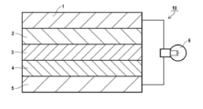
- FIG. 1 is a cross-sectional view schematically showing an all solid secondary battery (lithium ion secondary battery) according to a preferred embodiment of the present invention.
- the all solid secondary battery 10 of the present embodiment has a negative electrode current collector 1, a negative electrode active material layer 2, a solid electrolyte layer 3, a positive electrode active material layer 4, and a positive electrode current collector 5 in this order as viewed from the negative electrode side. .
- Each layer is in contact with each other and has a stacked structure. By adopting such a structure, at the time of charge, electrons (e ⁇ ) are supplied to the negative electrode side, and lithium ions (Li + ) are accumulated there.
- the solid electrolyte composition of the present invention can be preferably used as a molding material of an active material layer, particularly as a molding material of a negative electrode active material layer.
- the solid electrolyte-containing sheet of the present invention is suitable as a negative electrode active material layer and a positive electrode active material layer.
- the positive electrode active material layer and the negative electrode active material layer may be collectively referred to as an active material layer.
- the all solid secondary battery When an all solid secondary battery having the layer configuration shown in FIG. 1 is put in, for example, a 2032 coin case, the all solid secondary battery is referred to as an electrode sheet for all solid secondary batteries, and the electrode for all solid secondary batteries A battery manufactured by placing a sheet in a 2032 coin case may be called as an all solid secondary battery.
- At least one of the positive electrode active material layer 4, the solid electrolyte layer 3 and the negative electrode active material layer 2 is formed of the solid electrolyte composition of the present invention, or constituted of the solid electrolyte containing sheet of the present invention It is done.
- the components contained in the positive electrode active material layer 4, the solid electrolyte layer 3 and the negative electrode active material layer 2 may be the same as or different from each other.
- the negative electrode active material layer can be a lithium metal layer.
- a lithium metal layer the layer formed by depositing or shape
- the thickness of the lithium metal layer can be, for example, 1 to 500 ⁇ m regardless of the thickness of the negative electrode active material layer.
- the positive electrode current collector 5 and the negative electrode current collector 1 are preferably electron conductors.
- one or both of the positive electrode current collector and the negative electrode current collector may be simply referred to as a current collector.
- a current collector In addition to aluminum, aluminum alloy, stainless steel, nickel and titanium as materials for forming the positive electrode current collector, aluminum or stainless steel surface treated with carbon, nickel, titanium or silver (a thin film was formed are preferred, among which aluminum and aluminum alloys are more preferred.
- materials for forming the negative electrode current collector in addition to aluminum, copper, copper alloy, stainless steel, nickel and titanium etc., carbon, nickel, titanium or silver is treated on the surface of aluminum, copper, copper alloy or stainless steel Are preferred, with aluminum, copper, copper alloys and stainless steel being more preferred.
- the shape of the current collector is usually in the form of a film sheet, but a net, a punch, a lath body, a porous body, a foam, a molded body of a fiber group and the like can also be used.
- the thickness of the current collector is not particularly limited, but is preferably 1 to 500 ⁇ m. Further, it is also preferable to make the current collector surface uneven by surface treatment.
- the all solid secondary battery is formed by using the solid electrolyte composition of the present invention or at least one of the positive electrode active material layer, the solid electrolyte layer and the negative electrode active material layer, or by using the solid electrolyte containing sheet of the present invention It can be manufactured by an ordinary method. An example of the production of the all-solid secondary battery of the present invention will be described below.
- the all solid secondary battery of the present invention is a step of applying the solid electrolyte composition of the present invention on a substrate (for example, a metal foil serving as a current collector), forming a coated film, and drying the coated film. including. That is, it can manufacture via the manufacturing method of the solid electrolyte containing sheet
- a positive electrode active material layer is formed by applying and drying a solid electrolyte composition containing a positive electrode active material as a positive electrode composition on a metal foil that is a positive electrode current collector, and an all solid secondary battery A positive electrode sheet is produced.
- a composition for forming a solid electrolyte layer for forming a solid electrolyte layer is applied onto the positive electrode active material layer and dried to form a solid electrolyte layer. Furthermore, a negative electrode active material layer is formed by applying and drying a solid electrolyte composition containing a negative electrode active material as a negative electrode composition on the solid electrolyte layer.
- An all-solid secondary battery having a structure in which a solid electrolyte layer is sandwiched between a positive electrode active material layer and a negative electrode active material layer by overlapping a negative electrode current collector (metal foil) on the negative electrode active material layer Can. The above-mentioned drying does not have to be performed for each layer, and the composition may be dried after multi-layer coating.
- the all solid secondary battery can be enclosed in a case as required to form a desired form.
- the formation method of each layer is reversed, a negative electrode active material layer, a solid electrolyte layer, and a positive electrode active material layer are formed on the negative electrode current collector, and the positive electrode current collector is stacked to produce an all solid secondary battery.
- Another method is as follows. That is, as described above, a positive electrode sheet for an all solid secondary battery is produced. In addition, a solid electrolyte composition containing a negative electrode active material is applied as a negative electrode composition on a metal foil that is a negative electrode current collector to form a negative electrode active material layer, and a negative electrode sheet for an all solid secondary battery is obtained. Make. Next, a solid electrolyte layer is formed on one of the active material layers of these sheets as described above. Furthermore, on the solid electrolyte layer, the other of the all solid secondary battery positive electrode sheet and the all solid secondary battery negative electrode sheet is laminated such that the solid electrolyte layer and the active material layer are in contact with each other. In this way, an all solid secondary battery can be manufactured.
- the following method may be mentioned. That is, as described above, a positive electrode sheet for an all solid secondary battery and a negative electrode sheet for an all solid secondary battery are produced. Moreover, separately from this, the composition for solid electrolyte layer formation is apply
- An all solid secondary battery can also be manufactured by a combination of the above forming methods. For example, as described above, a positive electrode sheet for all solid secondary batteries, a negative electrode sheet for all solid secondary batteries, and a solid electrolyte-containing sheet for all solid secondary batteries are prepared. Subsequently, after laminating the solid electrolyte layer peeled off from the substrate on the negative electrode sheet for the all solid secondary battery, the all solid secondary battery can be manufactured by bonding it to the positive electrode sheet for the all solid secondary battery . In this method, the solid electrolyte layer can be laminated on the positive electrode sheet for the all solid secondary battery, and can be bonded to the negative electrode sheet for the all solid secondary battery.
- the application method of the solid electrolyte composition in the layer formation of the all solid secondary battery is not particularly limited and can be appropriately selected.
- application preferably wet application
- spray application spin coating application
- dip coating dip coating
- slit application stripe application and bar coating application
- the solid electrolyte composition or the like may be dried after being applied, or may be dried after being applied in multiple layers.
- the drying temperature is not particularly limited, and is preferably 30 ° C. or more, more preferably 60 ° C. or more, still more preferably 80 ° C. or more.
- the dispersion medium can be sufficiently evaporated to be in a solid state (coated dry layer). Moreover, it is preferable because the temperature is not excessively high and the members of the all solid secondary battery are not damaged.
- the applied pressure is not particularly limited, and may be a pressure at which the above component, for example, the inorganic solid electrolyte impairs the particle shape.
- the contact state and the binding state of the solid particles can be realized by forming a film of the solid electrolyte composition of the present invention, and even if pressure is subsequently applied, the state is not greatly impaired.
- the pressure is preferably in the range of 50 to 1,500 MPa.
- the applied solid electrolyte composition may be heated simultaneously with pressurization.
- the heating temperature is not particularly limited, and generally in the range of 30 to 300 ° C. It is also possible to press at a temperature higher than the glass transition temperature of the inorganic solid electrolyte.
- the atmosphere during pressurization is not particularly limited, and pressurization in dry air (dew point ⁇ 20 ° C. or less) and in an inert gas (for example, argon gas, helium gas, nitrogen gas) are not limited.
- the pressing time may be high pressure for a short time (for example, within several hours), or may be medium pressure for a long time (one day or more). Also, in order to keep applying medium pressure, restraints (such as screw tightening pressure) of the all solid secondary battery can be used.
- the pressing pressure may be uniform or different with respect to a pressure receiving portion such as a sheet surface.
- the press pressure can be changed according to the area and film thickness of the pressure-receiving portion. It is also possible to change the same site in stages with different pressures.
- the press surface may be smooth or roughened.
- the all solid secondary battery produced as described above is preferably initialized after production or before use.
- the initialization is not particularly limited, and can be performed, for example, by performing initial charge and discharge in a state where the press pressure is increased, and then releasing the pressure to the general working pressure of the all solid secondary battery.
- the all solid secondary battery of the present invention can be applied to various applications.
- the application mode is not particularly limited, for example, when installed in an electronic device, a laptop computer, a pen input computer, a mobile computer, an e-book player, a mobile phone, a cordless handset, a pager, a handy terminal, a mobile fax, a mobile phone Examples include copying, portable printers, headphone stereos, video movies, LCD TVs, handy cleaners, portable CDs, mini-discs, electric shavers, transceivers, electronic organizers, calculators, portable tape recorders, radios, backup power supplies, memory cards and the like.
- Other consumer products include automobiles (electric cars, etc.), electric vehicles, motors, lighting equipment, toys, game machines, road conditioners, watches, strobes, cameras, medical devices (pace makers, hearing aids, shoulder machines, etc.), etc. . Furthermore, it can be used for various military and space applications. It can also be combined with a solar cell.
- lithium sulfide Li 2 S, manufactured by Aldrich, purity> 99.98%) 2.42 g and diphosphorus pentasulfide (P 2 S) in a glove box under an argon atmosphere (dew point ⁇ 70 ° C.) (5 , manufactured by Aldrich, purity> 99%) 3.90 g of each was weighed, put into a mortar made of agate, and mixed for 5 minutes using a pestle made of agate.
- M-90G (trade name, manufactured by Shin-Nakamura Chemical Co., Ltd., methoxypolyethylene glycol methacrylate, molecular weight 400) in a 100 mL graduated cylinder 15.2 g, acrylonitrile 2.0 g, 2-ethylhexyl methacrylate 29.7 g, 3-mercaptoisobutyric acid 0.47 g and 0.47 g of V-601 (trade name, manufactured by Wako Pure Chemical Industries, Ltd.) were added and stirred to dissolve uniformly (solution B). The solution B was added dropwise to the solution A at 80 ° C. for 2 hours, and then the solution was further stirred at 80 ° C. for 2 hours, 95 ° C.
- the polymerization solution was poured into methanol to precipitate a polymer, and the operation of removing the solvent was repeated twice. Thereafter, 52 g of heptane was added to the precipitate to prepare a heptane solution.
- This heptane solution was used as a binder E-1 solution.
- the solid content concentration of the binder E-1 solution was 48 wt%, the weight average molecular weight (Mw) was 11,000, and the weight average molecular weight (Mn) was 6000.
- Binder E-2 solution in the same manner as the binder E-1 solution except that 4.3 g of butyl methacrylate and 23.8 g of 2-ethylhexyl methacrylate were used instead of 29.7 g of 2-ethylhexyl methacrylate I got The solid concentration was 47 wt%, Mw was 9000, and Mn was 4000.
- Binder E-3 Solution A binder E-3 solution was prepared in the same manner as in the preparation of the binder E-1 solution except that butyl methacrylate was used instead of M-90G (trade name, manufactured by Shin-Nakamura Chemical Co., Ltd., methoxypolyethylene glycol methacrylate, molecular weight 400). I got The solid concentration was 48 wt%, the Mw was 13,000, and the Mn was 7,000.
- Binder E-4 Solution A binder E-4 solution was obtained in the same manner as in the preparation of binder E-1, except that ethyl acrylate was used instead of acrylonitrile.
- the solid concentration was 46 wt%, Mw was 14000, and Mn was 9000.
- Binder B-1 Mixture Preparation of Binder B-1 Mixture
- 12.5 g of the binder E-1 solution and 17.5 g of heptane were charged, and the temperature was raised to 80 ° C. while stirring (solution A).
- 10.0 g of 2-methoxyethyl acrylate and 1.67 g of ALONIX M-5300 (trade name, manufactured by Toagosei Co., Ltd.) in a 50 mL graduated cylinder, V-601 (trade name, manufactured by Wako Pure Chemical Industries, Ltd.) 0. 53 g was added and stirred to dissolve uniformly (solution B).
- the solution B was added dropwise to the solution A at 80 ° C. over 2 hours, and then the mixture was further stirred at 80 ° C. for 2 hours and 90 ° C. for 2 hours for polymerization, and then cooled to room temperature.
- This dispersion was used as a binder B-1 mixed solution.
- the volume average particle diameter of the particulate binder constituting the dispersoid of the binder B-1 mixed liquid was 220 nm.
- polymers of various properties or characteristics are mixed and present in various states.
- the binder E-1 is dissolved and present in the dispersion medium (heptane), or in the interior or surface of the three-dimensional structure of the polymerization reactant in the preparation of the binder B-1 mixture. It exists by adsorption etc.
- the binder B-1 mixed solution most of the polymerization reaction products in the preparation of the binder B-1 mixed solution exist in the form of particles (dispersed state).
- low molecular weight polymerization reaction products and the like may be dissolved and present in the dispersion medium, or may be present in the dispersion medium as fine particles of extremely small particle diameter.
- the polymer present in the binder B-1 mixed solution is dissolved, exists in the form of particles of various sizes, or is soluble but is adsorbed inside or on the surface of the particles. Also, the polymer present in the binder B-1 mixture has a wide molecular weight distribution. The same applies to the mixture of binders B-2 to B-5 described later.
- Binder B-2 Mixture A binder B-2 mixed solution was obtained in the same manner as the preparation of the binder B-1 mixed solution except that the binder E-2 solution was used instead of the binder E-1 solution.
- the volume average particle diameter of the particulate binder constituting the dispersoid of the binder B-2 mixed liquid was 190 nm.
- Binder B-3 Mixture A binder B-3 mixed solution was obtained in the same manner as the preparation of the binder B-1 mixed solution except that 2-ethylhexyl acrylate was used instead of M-5300.
- the binder B-3 mixed solution was a highly viscous solution exhibiting yellowish turbidity.
- Binder B-4 Mixture A binder B-4 mixed solution was obtained in the same manner as the preparation of the binder B-1 mixed solution except that the binder E-3 solution was used instead of the binder E-1 solution.
- the volume average particle diameter of the particulate binder constituting the dispersoid of the binder B-4 mixed liquid was 200 nm.
- Binder B-5 Dispersion A binder B-5 mixed solution was obtained in the same manner as the preparation of the binder B-1 mixed solution except that the binder E-4 solution was used instead of the binder E-1 solution.
- the volume average particle diameter of the particulate binder constituting the dispersoid of the binder B-5 mixed liquid was 190 nm.
- this tube was set in the rotor of a small-sized ultracentrifuge (trade name: himac CS-150FNX, manufactured by Hitachi Koki), and subjected to ultracentrifugation at 100 000 rpm and 25 ° C. for 1 hour.
- the centrifugal force of this ultracentrifugation treatment is 610,000 G (this centrifugal force is the centrifugal force applied to the bottom of the tube).
- the binder which settled by this process and the binder which remained in the supernatant without settling were separated.
- Binder S-1 Containing Liquid Binder B-1 obtained by subjecting the binder B-1 mixed liquid to the above-mentioned [ultracentrifugation treatment of binder mixed liquid], precipitated binder a1 (first binder (B1)) and binder a2 remaining in supernatant (second binder) (B2)) and heptane were mixed to obtain a binder S-1 containing liquid.
- the binder S-1 containing liquid was prepared.
- the first binder (B1) was in the form of particles having a particle diameter of about 100 to 130 nm.
- Binder S-2 Containing Liquid A binder S-2 containing solution was prepared in the same manner as the binder S-1 containing solution except that the amount of the binder a1 contained in the vial was set to 0.12416 g and the amount of the binder a2 was set to 0.00384 g. .
- Binder S-3 Containing Liquid A binder S-3 containing solution was prepared in the same manner as the binder S-1 containing solution except that 0.11904 g of the binder a1 and 0.00896 g of the binder a2 were used in the vial. did.
- Binder S-4 Containing Liquid A binder S-4 containing solution is prepared in the same manner as the binder S-1 containing solution except that 0.11648 g of the binder a1 and 0.01152 g of the binder a2 are used in the vial. did.
- Binder S-5 Containing Liquid Binder B2 (first binder (B1)) obtained by subjecting the binder B-2 mixed liquid to the above-mentioned [ultracentrifugation treatment of binder] and binder b2 (second binder (B2) remaining in the supernatant liquid ) And heptane were mixed to obtain a binder S-5 containing solution.
- first binder (B1) obtained by subjecting the binder B-2 mixed liquid to the above-mentioned [ultracentrifugation treatment of binder] and binder b2 (second binder (B2) remaining in the supernatant liquid ) And heptane were mixed to obtain a binder S-5 containing solution.
- three components are placed in a vial so that the amount of binder b1 is 0.11904 g, the amount of binder b2 is 0.00896 g, and the amount of heptane is 1.152 g, and the mixture is stirred for 30 minutes using a mix rotor
- Binder S-6 Containing Liquid The binder B-3 mixed liquid was subjected to the above-mentioned [ultracentrifugation treatment of the binder], the precipitated binder c1 (first binder (B1)) and the binder c2 remaining in the supernatant (second binder (B2) ) And heptane were mixed to obtain a binder S-6-containing liquid. Specifically, the three components are placed in a vial so that the amount of binder c1 is 0.11904 g, the amount of binder c2 is 0.00896 g, and the amount of heptane is 1.152 g, and the mixture is stirred for 30 minutes using a mix rotor. By doing this, a binder S-6 containing liquid was prepared. In the binder S-6 containing liquid, the first binder (B1) was in the form of particles having a particle diameter of about 160 to 210 nm.
- Binder S-7-Containing Liquid The binder B-4 mixed liquid was subjected to the above-mentioned [ultracentrifugation treatment of binder], and the precipitated binder d1 (first binder (B1)) and the binder d2 remaining in the supernatant (second binder (B2) ) And heptane were mixed to obtain a binder S-7-containing liquid. Specifically, three components are placed in a vial so that the amount of binder d1 is 0.11904 g, the amount of binder d2 is 0.00896 g, and the amount of heptane is 1.152 g, and the mixture is stirred for 30 minutes using a mix rotor. By doing this, a binder S-7-containing liquid was prepared. In the binder S-7-containing liquid, the first binder (B1) was in the form of particles having a particle diameter of about 120 to 150 nm.
- Binder S-8-Containing Liquid The binder B-5 mixed liquid was subjected to the above-mentioned [ultracentrifugation treatment of binder], and the precipitated binder e1 (first binder (B1)) and the binder e2 remaining in the supernatant (second binder (B2) ) And heptane were mixed to obtain a binder S-8-containing liquid.
- the binder S-8-containing liquid was prepared.
- the first binder (B1) was in the form of particles having a particle diameter of about 140 to 200 nm.
- Binder T-1 Containing Liquid A binder T-1 containing liquid was prepared in the same manner as the binder S-1 containing liquid except that the amount of the binder a1 contained in the vial was 0.12710 g and the amount of the binder a2 was 0.000896 g. .
- Binder T-2 Containing Liquid A binder T-2 containing liquid was prepared in the same manner as the binder S-1 containing liquid except that the amount of the binder a1 contained in the vial was set to 0.11264 g and the amount of the binder a2 to 0.01536 g. .
- Binder T-3 Containing Liquid The binder B-1 mixed solution prepared above was diluted with heptane to obtain a diluted mixed solution containing 0.8 mass% of the polymer in total. 16 g of this diluted mixture (containing 0.128 g of polymer) was placed in a polypropylene tube (manufactured by Hitachi Koki Co., Ltd.) and sealed with a tube sealer (manufactured by Hitachi Koki Co., Ltd.).
- this tube was set in the rotor of a small-sized ultracentrifuge (trade name: himac CS-150FNX, manufactured by Hitachi Koki), and subjected to ultracentrifugation treatment at 50000 rpm and 25 ° C. for 1 hour.
- the centrifugal force of this ultracentrifugation treatment is 305000 G (this centrifugal force is the centrifugal force applied to the bottom of the tube).
- the binder a1-2 precipitated by this treatment and the binder a2-2 remaining in the supernatant without settling were separated.
- the binder a1-2 is used instead of the binder a1, the amount of the binder a1-2 put in the vial is 0.11904 g, and the binder a2-2 is used instead of the binder a2 and the amount of the binder a2-2 is 0
- a binder T-3 containing liquid was prepared in the same manner as in the preparation of the binder S-1 containing liquid except that the weight was changed to .00896 g.
- the binder composition of the binder (B) containing liquid prepared above is summarized in the following table.
- Preparation Example 1 Preparation of Solid Electrolyte Composition Into a 45 mL container made of zirconia (180 pieces of zirconia beads having a diameter of 5 mm) was charged, and the inorganic solid electrolyte shown in the table below and the binder prepared above (B) After charging the liquid containing and heptane as a dispersion medium, set the container in Fritsch's Planetary ball mill P-7 (trade name) and mix at a rotational speed of 300 rpm for 2 hours at room temperature to obtain a solid electrolyte composition. Prepared.
- the solid electrolyte composition contains a conductive aid
- ball mill P is combined with the inorganic solid electrolyte, the binder (B) -containing liquid prepared above, a conductive aid, and heptane as a dispersion medium.
- the solid electrolyte composition was prepared by mixing according to -7.
- the solid electrolyte composition contained an active material, the active material was charged, and the mixture was further mixed for 5 minutes at a rotation speed of 150 rpm at room temperature to prepare a solid electrolyte composition.
- Test Example 1 Evaluation of Layer Thickness Uniformity
- Each solid electrolyte-containing sheet obtained in the above Preparation Example 2 was cut into a rectangle of 3 cm ⁇ 5 cm.
- the cut sheet is divided into 0.5 cm, 1.5 cm, 2.5 cm, 3.5 cm, and 4.5 cm distances sequentially from the end in the major axis direction, and 0.5 cm in order from the end in the minor axis direction.
- the thickness of the sheet at the intersection of each of the major axis direction and the minor axis direction was measured.
- a constant pressure thickness measuring device (PG-FJ, manufactured by TEFLOCK CORPORATION) was used.
- the difference between the maximum value and the minimum value was determined, and the determined value was applied to the following evaluation criteria to evaluate the layer thickness uniformity.
- Test Example 2 Ion Conductivity
- Each solid electrolyte-containing sheet obtained in the above Preparation Example 2 was cut into a disk shape having a diameter of 14.5 mm.
- the solid electrolyte layer (electrode layer in the case of including the active material) of the two sheets cut out is pasted together to form a sheet for measuring ionic conductivity, and a spacer and a washer (not shown in FIG. 2) are incorporated to make stainless steel. It was placed in a made 2032 coin case 11.
- a crimped 2032 coin case 11 was used to produce a test body for measuring ionic conductivity, which was tightened with a force of 8 newtons (N) and had the configuration shown in FIG.
- the ion conductivity was measured using the test body for ion conductivity measurement obtained above. Specifically, the alternating current impedance was measured at a voltage amplitude of 5 mV and a frequency of 1 MHz to 1 Hz using a 1255 B FREQUENCY RESPONSE ANALYZER (trade name, manufactured by SOLARTRON) in a 30 ° C. constant temperature bath. Thereby, the resistance of the film thickness direction of the bonded solid electrolyte containing sheet (sheet for measuring ionic conductivity) was determined, and the ionic conductivity was determined by calculation according to the following formula (1). The obtained ion conductivity was applied to the following evaluation criteria and evaluated.
- Ion conductivity ⁇ (mS / cm) 1000 ⁇ sample film thickness (cm) / (resistance ( ⁇ ) ⁇ sample area (cm 2 )) (1)
- the sample film thickness means the thickness of the solid electrolyte layer or the electrode layer.
- the solid electrolyte-containing sheet formed using this composition has any effect. There was also a large variation in layer thickness. In addition, these solid electrolyte-containing sheets were inferior in ion conductivity (No. c11 to c15).
- the binder T-3 containing liquid is different from the definition of the present invention in the ultracentrifugation conditions when the binder B-1 mixed liquid is separated by the ultracentrifugation.
- the amount of precipitated components produced when the binder B-1 mixed solution is treated by this ultracentrifugation is the amount of precipitated components when the binder mixed solution B-1 is treated under the ultracentrifugation conditions defined in the present invention, and the appearance The clearness of the supernatant component was not changed either.
- Table 2 above the evaluation results were inferior. That is, in order to exert the effects of the present invention, it is important to divide the binder into two physical properties by the specific ultracentrifugation treatment specified in the present invention, and to set the blending amount of each binder to a specific ratio I understand that.
- the thickness of the solid electrolyte-containing sheet formed using this composition varies in all cases. It was small and excellent in ion conductivity (No. 11 to 27).
Abstract
Description
このような状況下、有機電解液に代えて、無機固体電解質を用いた全固体二次電池が注目されている。全固体二次電池は負極、電解質及び正極の全てが固体からなり、有機電解液を用いた電池において課題とされる安全性と信頼性を大きく改善することができ、また長寿命化も可能になるとされる。更に、全固体二次電池は、電極と電解質を直接並べて直列に配した積層構造とすることができる。そのため、有機電解液を用いた二次電池に比べて高エネルギー密度化が可能となり、電気自動車又は大型蓄電池等への応用が期待されている。 A lithium ion secondary battery is a storage battery that has a negative electrode, a positive electrode, and an electrolyte sandwiched between the negative electrode and the positive electrode, and enables charge and discharge by reciprocating lithium ions between the two electrodes. Conventionally, in lithium ion secondary batteries, organic electrolytes have been used as electrolytes. However, the organic electrolyte is liable to leak, and a short circuit may occur inside the battery due to overcharge or overdischarge, which may cause ignition, and further improvement of safety and reliability is required.
Under such circumstances, an all solid secondary battery using an inorganic solid electrolyte in place of the organic electrolyte has attracted attention. In the all solid secondary battery, all of the negative electrode, the electrolyte and the positive electrode are solid, which can greatly improve the safety and reliability issues in batteries using organic electrolytes, and can also extend the life. It will be. Furthermore, the all solid secondary battery can have a laminated structure in which the electrode and the electrolyte are directly arranged in series. Therefore, energy density can be increased as compared with a secondary battery using an organic electrolytic solution, and application to an electric car or a large storage battery is expected.
例えば特許文献1には、固体電解質層及び電極活物質層を形成するための各スラリー中に、粒子構造を有するポリマーと水溶性ポリマーとを含有する複合粒子バインダーを添加し、このスラリーを用いて全固体二次電池を製造したことが記載されている。特許文献1記載の技術によれば、全固体二次電池の出力特性と充放電サイクルとを改善できるとされる。 For practical use of such an all solid secondary battery, investigations of forming materials such as a solid electrolyte layer, an electrode active material layer on a positive electrode side or a negative electrode side are actively advanced.
For example, in Patent Document 1, a composite particle binder containing a polymer having a particle structure and a water-soluble polymer is added to each slurry for forming a solid electrolyte layer and an electrode active material layer, and this slurry is used. It is described that all solid secondary batteries were produced. According to the technology described in Patent Document 1, it is said that the output characteristics and charge / discharge cycle of the all solid secondary battery can be improved.
固体電解質層及び電極活物質層を構成する固体粒子間の結着性の向上のために、各層の形成材料に、樹脂で構成されたバインダーを添加することが検討されている。しかし、バインダーは一般にイオン伝導性を有しない。それゆえ、バインダーを添加すると抵抗が上昇し、所望のイオン伝導性を示す二次電池を得ることが難しくなる。
また、固体電解質層及び電極活物質層の形成材料には、無機固体電解質、活物質等の固体粒子が含まれているため、形成した層の厚さにばらつきが生じやすい。層厚のばらつきは、電池性能のばらつきの原因となる。また、形成する層の面積にも制約が生じ、例えば大型電池への適用に問題が生じるおそれがある。
そこで本発明は、無機固体電解質とバインダーと分散媒とを含有する固体電解質組成物であって、この組成物を用いて層を形成することにより、厚さがより均一な層形成が可能となり、また、この層が優れたイオン伝導性を示す固体電解質組成物を提供することを課題とする。
また、本発明は、より均一な層厚を実現でき、また優れたイオン伝導性を示す固体電解質含有シート、全固体二次電池用電極シート、及び全固体二次電池、並びにこれらの製造方法を提供することを課題とする。 In order to increase the energy density of the all solid secondary battery, it is necessary to laminate a solid electrolyte layer and an electrode active material layer. This lamination is usually performed under pressure conditions. Therefore, if the adhesion between the solid particles constituting the layer is not sufficient, defects such as cracks are likely to occur.
In order to improve the bondability between solid particles constituting the solid electrolyte layer and the electrode active material layer, it has been studied to add a binder made of a resin to the material for forming each layer. However, binders generally do not have ionic conductivity. Therefore, the addition of the binder increases the resistance and makes it difficult to obtain a secondary battery exhibiting desired ion conductivity.
In addition, since the forming material of the solid electrolyte layer and the electrode active material layer contains solid particles such as an inorganic solid electrolyte and an active material, the thickness of the formed layer tends to vary. The variation in layer thickness causes the variation in battery performance. In addition, the area of the layer to be formed is also restricted, which may cause problems in application to a large battery, for example.
Therefore, the present invention is a solid electrolyte composition containing an inorganic solid electrolyte, a binder, and a dispersion medium, and by forming a layer using this composition, it becomes possible to form a layer with a more uniform thickness. Another object of the present invention is to provide a solid electrolyte composition in which this layer exhibits excellent ion conductivity.
Moreover, the present invention can realize a solid electrolyte-containing sheet which can realize a more uniform layer thickness and exhibits excellent ion conductivity, an electrode sheet for an all solid secondary battery, an all solid secondary battery, and a method for producing them The task is to provide.
〔1〕
周期律表第一族若しくは第二族に属する金属のイオンの伝導性を有する無機固体電解質(A)と、バインダー(B)と、分散媒(C)とを含む固体電解質組成物であって、
上記バインダー(B)は、上記分散媒(C)中で温度25℃、遠心力610000Gで1時間の遠心分離処理に付した場合に沈降する第1バインダー(B1)と、上記遠心分離処理に付しても沈降しない第2バインダー(B2)とを含み、
上記第1バインダー(B1)の含有量Xと上記第2バインダー(B2)の含有量Yが、質量基準で下記式を満たす、固体電解質組成物。
0.01≦Y/(X+Y)<0.10
〔2〕
上記分散媒(C)が有機溶媒である、〔1〕記載の固体電解質組成物。
〔3〕
上記第1バインダー(B1)が粒子状バインダーである、〔1〕又は〔2〕記載の固体電解質組成物。
〔4〕
上記バインダー(B)を構成するポリマーが、ポリアルキレンオキサイド鎖を有する構成成分を含むポリマーを含む、〔1〕~〔4〕のいずれか記載の固体電解質組成物。
〔5〕
上記バインダー(B)を構成するポリマーが、ニトリル基を有する構成成分を含むポリマーを含む、〔1〕~〔4〕のいずれか記載の固体電解質組成物。
〔6〕
上記分散媒(C)が炭化水素溶媒を含む、〔1〕~〔5〕のいずれか記載の固体電解質組成物。
〔7〕
活物質(D)をさらに含有する、〔1〕~〔6〕のいずれか記載の固体電解質組成物。
〔8〕
導電助剤(E)をさらに含有する、〔1〕~〔7〕のいずれか記載の固体電解質組成物。
〔9〕
上記無機固体電解質(A)が硫化物系無機固体電解質である、〔1〕~〔8〕のいずれか記載の固体電解質組成物。
〔10〕
〔1〕~〔9〕のいずれか記載の固体電解質組成物を用いて形成した固体電解質含有シート。
〔11〕
周期律表第一族若しくは第二族に属する金属のイオンの伝導性を有する無機固体電解質(A)と、バインダー(B)と、溶媒(C1)とを含む固体電解質含有シートであって、
上記バインダー(B)は、上記溶媒(C1)中で温度25℃、遠心力610000Gで1時間の遠心分離処理に付した場合に沈降する第1バインダー(B1)と、上記遠心分離処理に付しても沈降しない第2バインダー(B2)とを含み、
上記第1バインダー(B1)の含有量Xと上記第2バインダー(B2)の含有量Yが、質量基準で下記式を満たす、固体電解質含有シート。
0.01≦Y/(X+Y)<0.10
〔12〕
〔10〕又は〔11〕記載の固体電解質含有シートを含む、全固体二次電池用電極シート。
〔13〕
正極活物質層と、負極活物質層と、上記正極活物質層及び上記負極活物質層の間の固体電解質層とを含む全固体二次電池であって、
上記正極活物質層、上記負極活物質層及び上記固体電解質層の少なくとも1層が、〔10〕又は〔11〕記載の固体電解質含有シートで構成された全固体二次電池。
〔14〕
〔1〕~〔9〕のいずれか記載の固体電解質組成物を基材上に塗布して塗布膜を形成する工程を含む、固体電解質含有シートの製造方法。
〔15〕
上記塗布膜を乾燥する工程を含む、〔14〕記載の固体電解質含有シートの製造方法。
〔16〕
〔14〕又は〔15〕記載の固体電解質含有シートの製造方法を含む全固体二次電池の製造方法。 That is, the above-mentioned subject was solved by the following means.
[1]
A solid electrolyte composition comprising an inorganic solid electrolyte (A) having conductivity of an ion of a metal belonging to Periodic Table Group 1 or
The binder (B) is added to the first binder (B1) which precipitates when it is subjected to centrifugation at a temperature of 25 ° C. and a centrifugal force of 610000 G for 1 hour in the dispersion medium (C); And a second binder (B2) which does not settle,
The solid electrolyte composition in which content X of said 1st binder (B1) and content Y of said 2nd binder (B2) satisfy | fill the following formula on a mass reference.
0.01 ≦ Y / (X + Y) <0.10
[2]
The solid electrolyte composition according to [1], wherein the dispersion medium (C) is an organic solvent.
[3]
The solid electrolyte composition according to [1] or [2], wherein the first binder (B1) is a particulate binder.
[4]
The solid electrolyte composition according to any one of [1] to [4], wherein the polymer constituting the binder (B) comprises a polymer containing a component having a polyalkylene oxide chain.
[5]
The solid electrolyte composition according to any one of [1] to [4], wherein the polymer constituting the binder (B) comprises a polymer containing a component having a nitrile group.
[6]
The solid electrolyte composition according to any one of [1] to [5], wherein the dispersion medium (C) contains a hydrocarbon solvent.
[7]
The solid electrolyte composition according to any one of [1] to [6], further comprising an active material (D).
[8]
The solid electrolyte composition according to any one of [1] to [7], further comprising a conductive auxiliary (E).
[9]
The solid electrolyte composition according to any one of [1] to [8], wherein the inorganic solid electrolyte (A) is a sulfide-based inorganic solid electrolyte.
[10]
A solid electrolyte-containing sheet formed using the solid electrolyte composition according to any one of [1] to [9].
[11]
A solid electrolyte-containing sheet comprising an inorganic solid electrolyte (A) having conductivity of an ion of a metal belonging to periodic group 1 group or
The binder (B) is subjected to the above-mentioned centrifugal separation treatment with the first binder (B1) which precipitates when it is subjected to a centrifugal treatment of 1 hour at a temperature of 25 ° C. and a centrifugal force of 610,000 G in the solvent (C1). And a second binder (B2) which does not settle,
A solid electrolyte containing sheet, wherein a content X of the first binder (B1) and a content Y of the second binder (B2) satisfy the following formula on a mass basis.
0.01 ≦ Y / (X + Y) <0.10
[12]
The electrode sheet for all the solid secondary batteries containing the solid electrolyte containing sheet as described in [10] or [11].
[13]
An all solid secondary battery including a positive electrode active material layer, a negative electrode active material layer, and a solid electrolyte layer between the positive electrode active material layer and the negative electrode active material layer,
The all-solid-state secondary battery by which at least 1 layer of the said positive electrode active material layer, the said negative electrode active material layer, and the said solid electrolyte layer was comprised with the solid electrolyte content sheet of [10] or [11] description.
[14]
A method for producing a solid electrolyte-containing sheet, comprising the steps of applying the solid electrolyte composition according to any one of [1] to [9] on a substrate to form a coated film.
[15]
The manufacturing method of the solid electrolyte content sheet of [14] description including the process of drying the said coating film.
[16]
The manufacturing method of the all-solid-state secondary battery containing the manufacturing method of the solid electrolyte containing sheet | seat as described in [14] or [15].
本発明の固体電解質含有シート、全固体二次電池用電極シート及び全固体二次電池は、より均一な層厚を実現でき、また、優れたイオン伝導性を示す。
本発明の固体電解質含有シート及び全固体二次電池の製造方法によれば、上述した本発明の固体電解質含有シート及び全固体二次電池を得ることができる。 The solid electrolyte composition of the present invention contains an inorganic solid electrolyte, a binder of a specific composition, and a dispersion medium, and when used as a layer forming material of an all solid secondary battery, layer formation with a more uniform thickness is achieved Also, this layer exhibits excellent ionic conductivity.
The solid electrolyte-containing sheet, the electrode sheet for an all solid secondary battery, and the all solid secondary battery of the present invention can realize a more uniform layer thickness and exhibit excellent ion conductivity.
According to the solid electrolyte containing sheet of the present invention and the manufacturing method of the all solid secondary battery, the solid electrolyte containing sheet of the present invention mentioned above and the all solid secondary battery can be obtained.
本発明の固体電解質組成物は、周期律表第一族若しくは第二族に属する金属のイオンの伝導性を有する無機固体電解質と、バインダー(B)と、分散媒(C)とを含む。
バインダー(B)は、分散媒(C)中に含有させた状態で超遠心分離処理したときに沈降するものと、沈降しないもの(上澄みに残留するもの)とを、特定の比で含んでいる。すなわちバインダー(B)は、バインダー(B)を分散媒(C)中に分散又は溶解し、温度25℃、遠心力610000Gで1時間の遠心分離処理(超遠心分離処理)に付した場合に、沈降する物性のバインダー(第1バインダー(B1))と、沈降せずに上澄み中に残留する物性のバインダー(第2バインダー(B2))とを含む。
本発明の固体電解質組成物中、第1バインダー(B1)の含有量Xと、第2バインダー(B2)の含有量Yとの関係が、質量基準で下記式を満たす。
0.01≦Y/(X+Y)<0.10
本発明の固体電解質組成物は、所望により後述する活物質(D)を含むことができる。また、導電助剤(E)を含んでいてもよい。これらを含有する固体電解質組成物は、電極活物質層の形成材料とすることができる。 [Solid Electrolyte Composition]
The solid electrolyte composition of the present invention includes an inorganic solid electrolyte having conductivity of an ion of a metal belonging to Periodic Table Group 1 or
The binder (B) contains, in a specific ratio, those which precipitate when subjected to ultracentrifugation treatment in the state of being contained in the dispersion medium (C) and those which do not precipitate (those which remain in the supernatant). . That is, when the binder (B) disperses or dissolves the binder (B) in the dispersion medium (C) and is subjected to centrifugal treatment (ultracentrifugal treatment) at a temperature of 25 ° C. and a centrifugal force of 610000 G for 1 hour, It contains a binder having a physical property to precipitate (first binder (B1)) and a binder having a physical property remaining in the supernatant without sedimentation (second binder (B2)).
In the solid electrolyte composition of the present invention, the relationship between the content X of the first binder (B1) and the content Y of the second binder (B2) satisfies the following formula on a mass basis.
0.01 ≦ Y / (X + Y) <0.10
The solid electrolyte composition of the present invention can optionally contain an active material (D) described later. Moreover, the conductive support agent (E) may be included. The solid electrolyte composition containing these can be made into the formation material of an electrode active material layer.
本発明において、無機固体電解質とは、無機の固体電解質のことであり、固体電解質とは、その内部においてイオンを移動させることができる固体状の電解質のことである。主たるイオン伝導性材料として有機物を含むものではないことから、有機固体電解質(ポリエチレンオキシド(PEO)などに代表される高分子電解質、リチウムビス(トリフルオロメタンスルホニル)イミド(LiTFSI)などに代表される有機電解質塩)とは明確に区別される。また、無機固体電解質は定常状態では固体であるため、通常カチオン及びアニオンに解離又は遊離していない。この点で、電解液、又は、ポリマー中でカチオン及びアニオンが解離若しくは遊離している無機電解質塩(LiPF6、LiBF4、LiFSI、LiClなど)とも明確に区別される。無機固体電解質は周期律表第一族若しくは第二族に属する金属のイオンの伝導性を有するものであれば特に制限されず電子伝導性を有さないものが一般的である。 <Inorganic solid electrolyte (A)>
In the present invention, the inorganic solid electrolyte is an inorganic solid electrolyte, and the solid electrolyte is a solid electrolyte capable of transferring ions inside thereof. An organic solid electrolyte (a polymer electrolyte represented by polyethylene oxide (PEO) or the like, an organic electrolyte represented by lithium bis (trifluoromethanesulfonyl) imide (LiTFSI) or the like because it does not contain an organic substance as a main ion conductive material It is clearly distinguished from electrolyte salt). In addition, since the inorganic solid electrolyte is solid in a steady state, it is not usually dissociated or released into cations and anions. In this respect, it is also clearly distinguished from the electrolyte solution or the inorganic electrolyte salt (LiPF 6 , LiBF 4 , LiFSI, LiCl, etc.) in which the cation and the anion are dissociated or released in the polymer. The inorganic solid electrolyte is not particularly limited as long as it has ion conductivity of a metal belonging to Periodic Table Group 1 or
本発明の全固体二次電池が全固体リチウムイオン二次電池である場合、無機固体電解質はリチウムイオンのイオン伝導度を有することが好ましい。 In the present invention, the inorganic solid electrolyte has ion conductivity of a metal belonging to Group 1 or
When the all solid secondary battery of the present invention is an all solid lithium ion secondary battery, the inorganic solid electrolyte preferably has an ion conductivity of lithium ion.
硫化物系無機固体電解質は、硫黄原子(S)を含有し、かつ、周期律表第一族若しくは第二族に属する金属のイオン伝導性を有し、かつ、電子絶縁性を有する化合物が好ましい。硫化物系無機固体電解質は、元素として少なくともLi、S及びPを含有し、リチウムイオン伝導性を有しているものが好ましいが、目的又は場合に応じて、Li、S及びP以外の他の元素を含んでもよい。 (I) Sulfide-based inorganic solid electrolyte A sulfide-based inorganic solid electrolyte contains a sulfur atom (S) and has ion conductivity of a metal belonging to Periodic Table 1 Group or
La1Mb1Pc1Sd1Ae1 式(I)
式中、LはLi、Na及びKから選択される元素を示し、Liが好ましい。Mは、B、Zn、Sn、Si、Cu、Ga、Sb、Al及びGeから選択される元素を示す。Aは、I、Br、Cl及びFから選択される元素を示す。a1~e1は各元素の組成比を示し、a1:b1:c1:d1:e1は1~12:0~5:1:2~12:0~10を満たす。a1は1~9が好ましく、1.5~7.5がより好ましい。b1は0~3が好ましく、0~1がより好ましい。d1は2.5~10が好ましく、3.0~8.5がより好ましい。e1は0~5が好ましく、0~3がより好ましい。 As a sulfide type inorganic solid electrolyte, the lithium ion conductive sulfide type inorganic solid electrolyte which satisfy | fills the composition shown by following formula (1) is mentioned, for example.
L a1 M b1 P c1 S d1 A e1 formula (I)
In the formula, L represents an element selected from Li, Na and K, and Li is preferred. M represents an element selected from B, Zn, Sn, Si, Cu, Ga, Sb, Al and Ge. A represents an element selected from I, Br, Cl and F. a1 to e1 represent composition ratios of respective elements, and a1: b1: c1: d1: e1 satisfies 1 to 12: 0 to 5: 1: 2 to 12: 0 to 10. 1 to 9 is preferable, and 1.5 to 7.5 is more preferable. 0 to 3 is preferable, and 0 to 1 is more preferable as b1. 2.5 to 10 are preferable and 3.0 to 8.5 of d1 are more preferable. 0 to 5 is preferable, and 0 to 3 is more preferable as e1.
硫化物系無機固体電解質は、例えば硫化リチウム(Li2S)、硫化リン(例えば五硫化二燐(P2S5))、単体燐、単体硫黄、硫化ナトリウム、硫化水素、ハロゲン化リチウム(例えばLiI、LiBr、LiCl)及び上記Mで表される元素の硫化物(例えばSiS2、SnS、GeS2)の中の少なくとも2つ以上の原料の反応により製造することができる。 The sulfide-based inorganic solid electrolyte may be non-crystalline (glass) or crystallized (glass-ceramicized), or only part of it may be crystallized. For example, a Li—P—S-based glass containing Li, P and S, or a Li—P—S-based glass ceramic containing Li, P and S can be used.
The sulfide-based inorganic solid electrolyte includes, for example, lithium sulfide (Li 2 S), phosphorus sulfide (for example, diphosphorus pentasulfide (P 2 S 5 )), single phosphorus, single sulfur, sodium sulfide, hydrogen sulfide, lithium halide (for example, It can be produced by the reaction of at least two or more of LiI, LiBr, LiCl) and sulfides of elements represented by the above M (eg, SiS 2 , SnS, GeS 2 ).
酸化物系無機固体電解質は、酸素原子(O)を含有し、かつ、周期律表第一族若しくは第二族に属する金属のイオン伝導性を有し、かつ、電子絶縁性を有する化合物が好ましい。 (Ii) Oxide-Based Inorganic Solid Electrolyte The oxide-based inorganic solid electrolyte contains an oxygen atom (O) and has ion conductivity of a metal belonging to
無機固体電解質粒子の粒径は平均粒径を意味し、以下の通り決定することができる。
無機固体電解質粒子を、水(水に不安定な物質の場合はヘプタン)を用いて20mLサンプル瓶中で1質量%の分散液を希釈調整する。希釈後の分散試料は、1kHzの超音波を10分間照射し、その直後に試験に使用する。この分散液試料を用い、レーザ回折/散乱式粒度分布測定装置LA-920(商品名、HORIBA社製)を用いて、温度25℃で測定用石英セルを使用してデータ取り込みを50回行い、体積平均粒子径を得る。その他の詳細な条件等は必要によりJIS Z 8828:2013「粒子径解析-動的光散乱法」の記載を参照する。1水準につき5つの試料を作製しその平均値を採用する。 The inorganic solid electrolyte is preferably in the form of particles. In this case, the particle size of the inorganic solid electrolyte is not particularly limited. The particle diameter of the inorganic solid electrolyte is preferably 0.01 μm or more, more preferably 0.2 μm or more, and still more preferably 0.3 μm or more, in terms of ion conductivity, further processability and interface formation. The particle size of the inorganic solid electrolyte is preferably 100 μm or less, more preferably 50 μm or less, still more preferably 20 μm or less, still more preferably 4 μm or less, and particularly preferably 2 μm or less.
The particle size of the inorganic solid electrolyte particles means the average particle size and can be determined as follows.
The inorganic solid electrolyte particles are diluted with water (heptane for water labile substances) in a 20 mL sample bottle to dilute the 1 wt% dispersion. The diluted dispersed sample is irradiated with 1 kHz ultrasound for 10 minutes, and used immediately thereafter for the test. Using this dispersion liquid sample, using a laser diffraction / scattering particle size distribution analyzer LA-920 (trade name, manufactured by HORIBA), data acquisition is performed 50 times using a quartz cell for measurement at a temperature of 25 ° C. Obtain volume average particle size. For other detailed conditions, etc., refer to the description of JIS Z 8828: 2013 "Particle diameter analysis-dynamic light scattering method" as necessary. Make five samples per level and adopt the average value.
無機固体電解質の、固体電解質組成物中の含有量は、特に制限されない。全固体二次電池に用いたときの界面抵抗の低減及び低減された界面抵抗の維持を考慮したとき、組成物中の固形成分100質量部中、無機固体電解質が5質量部以上であることが好ましく、10質量部以上であることがより好ましく、20質量部以上であることが特に好ましい。また同様の観点から、組成物中の固形成分100質量部中、無機固体電解質が99.9質量部以下であることが好ましく、99.5質量部以下であることがより好ましく、99質量部以下であることが特に好ましい。
本発明において、固形分(固形成分)とは、固体電解質組成物を、1mmHgの気圧下、窒素雰囲気下120℃で6時間乾燥処理したときに、揮発又は蒸発して消失しない成分をいう。典型的には、後述の分散媒以外の成分を指す。 The inorganic solid electrolyte may be used singly or in combination of two or more.
The content of the inorganic solid electrolyte in the solid electrolyte composition is not particularly limited. The inorganic solid electrolyte is at least 5 parts by mass in 100 parts by mass of the solid component in the composition, taking into consideration the reduction of the interface resistance and the maintenance of the reduced interface resistance when used in an all solid secondary battery The amount is preferably 10 parts by mass or more, and more preferably 20 parts by mass or more. From the same viewpoint, the inorganic solid electrolyte is preferably 99.9 parts by mass or less, more preferably 99.5 parts by mass or less, and 99 parts by mass or less in 100 parts by mass of the solid components in the composition. Is particularly preferred.
In the present invention, the solid content (solid component) refers to a component which does not evaporate or evaporate when the solid electrolyte composition is dried at 120 ° C. under a nitrogen atmosphere for 6 hours under a pressure of 1 mmHg. Typically, it refers to components other than the dispersion medium described later.
本発明の固体電解質組成物は、バインダー(B)を含有する。組成物中に含まれるバインダー(B)は、各種の高分子(ポリマー)で構成することができる。バインダー(B)は、粒子状のものを含んでもよいし、非粒子状のものを含んでもよい。本発明の固体電解質組成物は後述のように、特定条件下における超遠心分離処理において、沈降成分となる物性のものと、上澄み成分となる物性のものを特定比で含む。 <Binder (B)>
The solid electrolyte composition of the present invention contains a binder (B). The binder (B) contained in the composition can be composed of various polymers. The binder (B) may contain particulates or non-particulates. As described later, the solid electrolyte composition of the present invention contains, at a specific ratio, physical properties to be precipitated components and physical properties to be supernatant components in the ultracentrifugation treatment under specific conditions.
含フッ素樹脂としては、例えば、ポリテトラフルオロエチレン(PTFE)、ポリビニレンジフルオリド(PVdF)、ポリビニレンジフルオリドとヘキサフルオロプロピレンとの共重合体(PVdF-HFP)が挙げられる。 (Fluorinated resin)
Examples of the fluorine-containing resin include polytetrafluoroethylene (PTFE), polyvinylidene fluoride (PVdF), and a copolymer of polyvinylidene fluoride and hexafluoropropylene (PVdF-HFP).
炭化水素系熱可塑性樹脂としては、例えば、ポリエチレン、ポリプロピレン、スチレンブタジエンゴム(SBR)、水素添加スチレンブタジエンゴム(HSBR)、ブチレンゴム、アクリロニトリルブタジエンゴム、ポリブタジエン、ポリイソプレンが挙げられる。 (Hydrocarbon-based thermoplastic resin)
Examples of the hydrocarbon-based thermoplastic resin include polyethylene, polypropylene, styrene butadiene rubber (SBR), hydrogenated styrene butadiene rubber (HSBR), butylene rubber, acrylonitrile butadiene rubber, polybutadiene, and polyisoprene.
(メタ)アクリル樹脂としては、各種の(メタ)アクリルモノマー、(メタ)アクリルアミドモノマー、及びこれらモノマーの2種以上の共重合体が挙げられる。
また、その他のビニル系モノマーとの共重合体(コポリマー)も好適に用いられる。例えば、(メタ)アクリル酸メチルとスチレンとの共重合体、(メタ)アクリル酸メチルとアクリロニトリルとの共重合体、(メタ)アクリル酸ブチルとアクリロニトリルとスチレンとの共重合体が挙げられるが、これらに限定されるものではない。本願明細書において、コポリマーは、統計コポリマー及び周期コポリマーのいずれでもよく、ランダムコポリマーが好ましい。 ((Meth) acrylic resin)
Examples of the (meth) acrylic resin include various (meth) acrylic monomers, (meth) acrylamide monomers, and copolymers of two or more of these monomers.
In addition, copolymers (copolymers) with other vinyl monomers are also suitably used. Examples include copolymers of methyl (meth) acrylate and styrene, copolymers of methyl (meth) acrylate and acrylonitrile, and copolymers of butyl (meth) acrylate, acrylonitrile and styrene. It is not limited to these. As used herein, the copolymer may be either a statistical copolymer or a periodic copolymer, with random copolymers being preferred.
その他の樹脂としては、例えば、ポリウレタン樹脂、ポリウレア樹脂、ポリアミド樹脂、ポリイミド樹脂、ポリエステル樹脂、ポリエーテル樹脂、ポリカーボネート樹脂、セルロース誘導体樹脂等が挙げられる。 (Other resin)
Examples of other resins include polyurethane resin, polyurea resin, polyamide resin, polyimide resin, polyester resin, polyether resin, polycarbonate resin, and cellulose derivative resin.
上記各種の樹脂は、市販品を用いることができる。また、常法により調製することもできる。
なお、上記で説明した有機樹脂は一例であり、本発明におけるバインダー(B)はこれらの形態に限定されるものではない。 Among the above, fluorine-containing resins, hydrocarbon-based thermoplastic resins, (meth) acrylic resins, polyurethane resins, polycarbonate resins and cellulose derivative resins are preferable, and they have good affinity with inorganic solid electrolytes, and resins themselves A (meth) acrylic resin or a polyurethane resin is particularly preferred in that it has good flexibility and can exhibit stronger binding to solid particles.
A commercial item can be used for said various resin. Moreover, it can also prepare by a conventional method.
In addition, the organic resin demonstrated above is an example, and the binder (B) in this invention is not limited to these forms.
(条件)
カラム:TOSOH TSKgel Super HZM-H(商品名)、TOSOH TSKgel Super HZ4000(商品名)、TOSOH TSKgel Super HZ2000(商品名)をつないだカラムを用いる。
キャリア:テトラヒドロフラン
測定温度:40℃
キャリア流量:1.0mL/min
試料濃度:0.1質量%
検出器:RI(屈折率)検出器 In the present invention, the weight average molecular weight of a polymer refers to a weight average molecular weight in terms of standard polystyrene by gel permeation chromatography (GPC) unless otherwise specified. The measured value is a value measured under the following conditions. However, depending on the type of polymer, an appropriate eluent can be selected and used.
(conditions)
Columns: TOSOH TSKgel Super HZM-H (trade name), TOSOH TSKgel Super HZ 4000 (trade name), and TOSOH TSKgel Super HZ 2000 (trade name) are used together.
Carrier: Tetrahydrofuran Measurement temperature: 40 ° C
Carrier flow rate: 1.0 mL / min
Sample concentration: 0.1% by mass
Detector: RI (refractive index) detector
0.01≦Y/(X+Y)<0.10
つまり、固体電解質組成物に含まれるバインダー(B)を構成する高分子中、超遠心分離処理では沈降せずに上澄みに存在する物性の高分子の割合は、1質量%以上10質量%未満である。換言すれば、バインダー(B)を構成する高分子中、超遠心分離処理によっても、分散媒中に溶解し、及び/又は、極小粒径の樹脂微粒子として分散媒中に存在する物性の高分子の割合は、1質量%以上10質量%未満である。
他方、第1バインダー(B1)は、分散媒中において、通常は樹脂微粒子として存在する。
本発明の固体電解質組成物中において、第1バインダー(B1)と第2バインダー(B2)は、独立して存在していてもよいし、互いに相互作用(吸着等)した状態で存在していてもよい。
第1バインダー(B1)の含有量Xと、第2バインダー(B2)の含有量Yとの関係は、質量基準で下記式を満たすことが好ましく、
0.015≦Y/(X+Y)≦0.09
下記式を満たすことがより好ましく、
0.02≦Y/(X+Y)≦0.08
下記式を満たすことがさらに好ましい。
0.025≦Y/(X+Y)≦0.075 In the solid electrolyte composition of the present invention, the relationship between the content X of the first binder (B1) and the content Y of the second binder (B2) satisfies the following formula on a mass basis.
0.01 ≦ Y / (X + Y) <0.10
That is, in the polymer constituting the binder (B) contained in the solid electrolyte composition, the proportion of the polymer having physical properties present in the supernatant without sedimentation in the ultracentrifugation treatment is 1 mass% or more and less than 10 mass% is there. In other words, in the polymer constituting the binder (B), the polymer having the physical properties of being dissolved in the dispersion medium even by the ultracentrifugation treatment and / or existing in the dispersion medium as resin fine particles of extremely small particle diameter The ratio of is 1% by mass or more and less than 10% by mass.
On the other hand, the first binder (B1) is usually present as fine resin particles in the dispersion medium.
In the solid electrolyte composition of the present invention, the first binder (B1) and the second binder (B2) may be present independently or in an interactive (adsorbed etc.) state. It is also good.
The relationship between the content X of the first binder (B1) and the content Y of the second binder (B2) preferably satisfies the following formula on a mass basis,
0.015 ≦ Y / (X + Y) ≦ 0.09
It is more preferable to satisfy the following formula,
0.02 ≦ Y / (X + Y) ≦ 0.08
It is more preferable to satisfy the following formula.
0.025 ≦ Y / (X + Y) ≦ 0.075
これに対し、本発明の固体電解質組成物では、分散媒に難溶性で超遠心分離処理により沈降成分となる第1バインダー(B1)に加え、分散媒中に溶解し又は極小サイズの粒子状として存在し、超遠心分離処理により上澄み成分となる第2バインダー(B2)を特定量含有させる。つまり、単に微粒子ポリマーをバインダーとして用いる技術とは発想を異にする。これにより、この組成物を用いて形成した層は界面抵抗の上昇が効果的に抑えられ、イオン伝導度に優れたものとなる。また、このようなバインダー組成を採用することにより、この固体電解質組成物を用いて形成した層は、層全体の厚さがより均一化されたものとなる。この理由は定かではないが、第1バインダー(B1)が固体粒子表面を被覆せずに部分的に覆うことにより、イオン伝導性の低下を生じることなく固体粒子間の結着性を高めることができること、また、第2バインダー(B2)が固体粒子の分散剤のようにも働き、スラリー中の固体粒子の凝集を抑制することなどが複合的に作用していると考えられる。 In the solid electrolyte composition, when the binder is in a state of being dissolved in the dispersion medium, the binder covers almost the entire solid particle surface in the layer formed using the binder. This state can enhance the binding between solid particles, but usually the interface resistance increases and the ion conductivity decreases. Therefore, as described in, for example, JP-A-2015-088486, a binder is made to be present in the form of particles using a resin that does not dissolve in the dispersion medium, and the binding property between solid particles is enhanced in the formed layer. There are reports of techniques to suppress the increase in interface resistance.
On the other hand, in the solid electrolyte composition of the present invention, it is added to the first binder (B1) which is hardly soluble in the dispersion medium and becomes a sedimentation component by the ultracentrifugation treatment, and dissolved in the dispersion medium or A specific amount of a second binder (B2) which is present and becomes a supernatant component by ultracentrifugation treatment is contained. In other words, the concept is different from the technology in which only the fine particle polymer is used as the binder. As a result, in the layer formed using this composition, the increase in interface resistance can be effectively suppressed and the ion conductivity becomes excellent. Moreover, by employing such a binder composition, the layer formed using this solid electrolyte composition has a more uniform thickness throughout. Although the reason for this is not clear, the first binder (B1) may partially cover the surface of the solid particle without covering it, thereby enhancing the binding property between the solid particles without causing a decrease in ion conductivity. It is also considered that the second binder (B2) acts as a dispersant for solid particles and acts in a complex manner to suppress the aggregation of the solid particles in the slurry.
第1バインダー(B1)は超遠心分離処理によって上記の挙動を示す。本発明の固体電解質組成物中において、第1バインダー(B1)は通常は粒子状である。第1バインダー(B1)の粒径は10~10000nmが好ましく、50~1000nmがより好ましく、100~500nmがさらに好ましい。バインダー粒子の粒径は一次粒子の平均粒径を意味する。バインダー粒子の平均粒径の測定は無機固体電解質の粒径と同様にして決定することができる。バインダー粒子の粒径が上記装置の測定限界以下の場合は、必要によりバインダー樹脂粒子を乾固した後に、透過型電子顕微鏡(TEM)観察により粒径を測定する。 (First binder (B1))
The first binder (B1) exhibits the above behavior by ultracentrifugation treatment. In the solid electrolyte composition of the present invention, the first binder (B1) is usually in the form of particles. The particle diameter of the first binder (B1) is preferably 10 to 10000 nm, more preferably 50 to 1000 nm, and still more preferably 100 to 500 nm. The particle size of the binder particles means the average particle size of primary particles. The measurement of the average particle size of the binder particles can be determined in the same manner as the particle size of the inorganic solid electrolyte. When the particle size of the binder particles is equal to or less than the measurement limit of the above-mentioned apparatus, the binder resin particles are dried if necessary, and then the particle size is measured by transmission electron microscope (TEM) observation.
第2バインダー(B2)は超遠心分離処理によって上記の挙動を示す。第2バインダー(B2)は、組成物を構成する分散媒に溶解性であるか、あるいは組成物を構成する分散媒中において極小粒径の粒子状として存在する高分子である。また、第2バインダー(B2)は第1バインダー(B1)と相互作用(吸着等)した状態で存在してもよい。
第2バインダー(B2)を構成する高分子の数平均分子量は、固体粒子への吸着率向上の観点から1000~100000が好ましく、3000~50000がより好ましい。 (2nd binder (B2))
The second binder (B2) exhibits the above behavior by ultracentrifugation treatment. The second binder (B2) is a polymer that is soluble in the dispersion medium that constitutes the composition, or is present as particles with a very small particle diameter in the dispersion medium that constitutes the composition. The second binder (B2) may be present in a state of interaction (adsorption, etc.) with the first binder (B1).
The number average molecular weight of the polymer constituting the second binder (B2) is preferably 1000 to 100000, and more preferably 3000 to 50000, from the viewpoint of improving the adsorption rate to the solid particles.
また、バインダー(B)は、凝集力向上によるラテックス粒子の塗布溶剤に対する膨潤の抑制の観点から、バインダー(B)を構成するポリマーが、ニトリル基(シアノ基)を有する構成成分を含むポリマーを含むことも好ましい。 It is preferable that the polymer which comprises a binder (B) contains the polymer containing the component which has a polyalkylene oxide chain from a viewpoint of the improvement of the adsorption amount with respect to solid particle | grains by high polarization.
In addition, the binder (B) contains a polymer containing a component having a nitrile group (cyano group), from the viewpoint of suppressing the swelling of the latex particles with respect to the coating solvent due to the improvement of cohesive force Is also preferred.
また、本発明の固体電解質組成物において、バインダー(B)の含有量に対する、固体粒子(無機固体電解質と活物質の合計)の含有量の質量比[(無機固体電解質の質量+活物質の質量)/バインダー樹脂粒子の質量]は、1000~1の範囲が好ましく、500~2がより好ましく、100~10がさらに好ましい。 In the solid electrolyte composition of the present invention, the total content of the first binder (B1) and the second binder (B2) is the reduction in interface resistance and the reduction in interface resistance when used in an all solid secondary battery. When maintenance is considered, 0.01 mass part or more is preferable in 100 mass parts of solid components, 0.1 mass part or more is more preferable, and 1 mass part or more is still more preferable. Further, from the viewpoint of battery performance, 20 parts by mass or less is preferable, 10 parts by mass or less is more preferable, and 5 parts by mass or less is still more preferable.
In the solid electrolyte composition of the present invention, the mass ratio of the content of solid particles (total of inorganic solid electrolyte and active material) to the content of the binder (B) [(mass of inorganic solid electrolyte + mass of active material) The weight of binder resin particles] is preferably in the range of 1000 to 1, more preferably 500 to 2, and still more preferably 100 to 10.
本発明の固体電解質組成物は、周期律表第一族若しくは第二族に属する金属元素のイオンの挿入放出が可能な活物質を含有してもよい。活物質としては、正極活物質及び負極活物質が挙げられる。活物質を含む固体電解質組成物は、全固体二次電池の電極活物質層の形成に好適に用いることができる。 <Active material (D)>
The solid electrolyte composition of the present invention may contain an active material capable of inserting and releasing ions of a metal element belonging to Group 1 or
本発明において、活物質(正極活物質又は負極活物質)を含有する固体電解質組成物を、電極用組成物(正極用組成物又は負極用組成物)ということがある。 The active material includes a positive electrode active material and a negative electrode active material, and is a metal oxide (preferably a transition metal oxide) which is a positive electrode active material, or a metal oxide which is a negative electrode active material or Sn, Si, Al and Metals capable of alloying with lithium such as In are preferred.
In the present invention, a solid electrolyte composition containing an active material (positive electrode active material or negative electrode active material) may be referred to as a composition for an electrode (composition for positive electrode or a composition for negative electrode).
正極活物質は、可逆的にリチウムイオンを挿入及び放出できるものが好ましい。その材料は、上記特性を有するものであれば、特に制限はなく、遷移金属酸化物、又は、有機物、硫黄などのLiと複合化できる元素や硫黄と金属の複合物などでもよい。
中でも、正極活物質としては、遷移金属酸化物を用いることが好ましく、遷移金属元素Ma(Co、Ni、Fe、Mn、Cu及びVから選択される1種以上の元素)を有する遷移金属酸化物がより好ましい。また、この遷移金属酸化物に元素Mb(リチウム以外の金属周期律表の第1(Ia)族の元素、第2(IIa)族の元素、Al、Ga、In、Ge、Sn、Pb、Sb、Bi、Si、P又はBなどの元素)を混合してもよい。Mbの混合量としては、遷移金属元素Maの量(100mol%)に対して0~30mol%が好ましい。Li/Maのモル比が0.3~2.2になるように混合して合成されたものが、より好ましい。
遷移金属酸化物の具体例としては、(MA)層状岩塩型構造を有する遷移金属酸化物、(MB)スピネル型構造を有する遷移金属酸化物、(MC)リチウム含有遷移金属リン酸化合物、(MD)リチウム含有遷移金属ハロゲン化リン酸化合物及び(ME)リチウム含有遷移金属ケイ酸化合物等が挙げられる。 (Positive electrode active material)
The positive electrode active material is preferably one capable of reversibly inserting and releasing lithium ions. The material is not particularly limited as long as it has the above-described characteristics, and may be a transition metal oxide, an organic substance, an element capable of being complexed with Li such as sulfur, a complex of sulfur and a metal, or the like.
Among them, it is preferable to use a transition metal oxide as the positive electrode active material, and a transition metal oxide having a transition metal element M a (one or more elements selected from Co, Ni, Fe, Mn, Cu and V) Are more preferred. Further, in this transition metal oxide, an element M b (an element of Group 1 (Ia) other than lithium, an element of Group 1 (Ia) of the metal periodic table, an element of Group 2 (IIa), Al, Ga, In, Ge, Sn, Pb, Elements such as Sb, Bi, Si, P or B may be mixed. The mixing amount of M b is preferably 0 to 30 mol% with respect to the amount (100 mol%) of the transition metal element M a . It is more preferable to be synthesized by mixing so that the molar ratio of Li / M a is 0.3 to 2.2.
Specific examples of the transition metal oxide include a transition metal oxide having a (MA) layered rock salt type structure, a transition metal oxide having a (MB) spinel type structure, a (MC) lithium-containing transition metal phosphate compound, (MD And the like) lithium-containing transition metal halogenated phosphoric acid compounds and (ME) lithium-containing transition metal silicate compounds.
(MB)スピネル型構造を有する遷移金属酸化物の具体例として、LiMn2O4(LMO)、LiCoMnO4、Li2FeMn3O8、Li2CuMn3O8、Li2CrMn3O8及びLi2NiMn3O8が挙げられる。
(MC)リチウム含有遷移金属リン酸化合物としては、例えば、LiFePO4及びLi3Fe2(PO4)3等のオリビン型リン酸鉄塩、LiFeP2O7等のピロリン酸鉄類、LiCoPO4等のリン酸コバルト類並びにLi3V2(PO4)3(リン酸バナジウムリチウム)等の単斜晶ナシコン型リン酸バナジウム塩が挙げられる。
(MD)リチウム含有遷移金属ハロゲン化リン酸化合物としては、例えば、Li2FePO4F等のフッ化リン酸鉄塩、Li2MnPO4F等のフッ化リン酸マンガン塩及びLi2CoPO4F等のフッ化リン酸コバルト類が挙げられる。
(ME)リチウム含有遷移金属ケイ酸化合物としては、例えば、Li2FeSiO4、Li2MnSiO4及びLi2CoSiO4等が挙げられる。
本発明では、(MA)層状岩塩型構造を有する遷移金属酸化物が好ましく、LCO又はNMCがより好ましい。 As specific examples of transition metal oxides having a layered rock salt type structure, LiCoO 2 (lithium cobaltate [LCO]), LiNi 2 O 2 (lithium nickelate), LiNi 0.85 Co 0.10 Al 0. 05 O 2 (lithium nickel cobalt aluminate [NCA]), LiNi 1/3 Co 1/3 Mn 1/3 O 2 (lithium nickel manganese cobaltate [NMC]) and LiNi 0.5 Mn 0.5 O 2 ( And lithium manganese nickelate).
Specific examples of the transition metal oxide having a (MB) spinel structure include LiMn 2 O 4 (LMO), LiCoMnO 4 , Li 2 FeMn 3 O 8 , Li 2 CuMn 3 O 8 , Li 2 CrMn 3 O 8 and Li 2 NiMn 3 O 8 and the like.
Examples of (MC) lithium-containing transition metal phosphate compounds include olivine-type iron phosphates such as LiFePO 4 and Li 3 Fe 2 (PO 4 ) 3 , iron pyrophosphates such as LiFeP 2 O 7 , LiCoPO 4 etc. Cobalt phosphates and monoclinic Nasacon type vanadium phosphate salts such as Li 3 V 2 (PO 4 ) 3 (lithium vanadium phosphate).
(MD) as the lithium-containing transition metal halogenated phosphate compound, for example,
Examples of the (ME) lithium-containing transition metal silicate compound include Li 2 FeSiO 4 , Li 2 MnSiO 4 and Li 2 CoSiO 4 .
In the present invention, transition metal oxides having a (MA) layered rock salt type structure are preferred, and LCO or NMC is more preferred.
正極活物質層を形成する場合、正極活物質層の単位面積(cm2)当たりの正極活物質の質量(mg)(目付量)は特に制限されるものではない。設計された電池容量に応じて、適宜に決めることができる。 The positive electrode active materials may be used alone or in combination of two or more.
When forming a positive electrode active material layer, the mass (mg) (area weight) of the positive electrode active material per unit area (cm 2 ) of the positive electrode active material layer is not particularly limited. It can be determined appropriately depending on the designed battery capacity.
負極活物質は、可逆的にリチウムイオンを挿入及び放出できるものが好ましい。その材料は、上記特性を有するものであれば、特に制限はなく、炭素質材料、酸化錫等の金属酸化物、酸化ケイ素、金属複合酸化物、リチウム単体及びリチウムアルミニウム合金等のリチウム合金、並びに、Sn、Si、Al及びIn等のリチウムと合金形成可能な金属等が挙げられる。中でも、炭素質材料又はリチウム複合酸化物が信頼性の点から好ましく用いられる。また、金属複合酸化物としては、リチウムを吸蔵及び放出可能であることが好ましい。その材料は、特には制限されないが、構成成分としてチタン及び/又はリチウムを含有していることが、高電流密度充放電特性の観点で好ましい。 (Anode active material)
The negative electrode active material is preferably one capable of reversibly inserting and releasing lithium ions. The material is not particularly limited as long as it has the above-mentioned characteristics, and carbonaceous materials, metal oxides such as tin oxide, silicon oxides, metal complex oxides, lithium alone such as lithium alloy and lithium aluminum alloy, and And metals such as Sn, Si, Al and In which can be alloyed with lithium. Among them, carbonaceous materials or lithium composite oxides are preferably used from the viewpoint of reliability. Moreover, as a metal complex oxide, it is preferable that lithium can be occluded and released. The material is not particularly limited, but it is preferable in view of high current density charge and discharge characteristics that titanium and / or lithium is contained as a component.
負極活物質層を形成する場合、負極活物質層の単位面積(cm2)当たりの負極活物質の質量(mg)(目付量)は特に制限されるものではない。設計された電池容量に応じて、適宜に決めることができる。 The negative electrode active materials may be used alone or in combination of two or more.
When the negative electrode active material layer is formed, the mass (mg) (area weight) of the negative electrode active material per unit area (cm 2 ) of the negative electrode active material layer is not particularly limited. It can be determined appropriately depending on the designed battery capacity.
正極活物質及び負極活物質の表面は別の金属酸化物で表面被覆されていてもよい。表面被覆剤としてはTi、Nb、Ta、W、Zr、Al、Si又はLiを含有する金属酸化物等が挙げられる。具体的には、チタン酸スピネル、タンタル系酸化物、ニオブ系酸化物、ニオブ酸リチウム系化合物等が挙げられ、具体的には、Li4Ti5O12、Li2Ti2O5、LiTaO3、LiNbO3、LiAlO2、Li2ZrO3、Li2WO4、Li2TiO3、Li2B4O7、Li3PO4、Li2MoO4、Li3BO3、LiBO2、Li2CO3、Li2SiO3、SiO2、TiO2、ZrO2、Al2O3、B2O3等が挙げられる。
また、正極活物質又は負極活物質を含む電極表面は硫黄又はリンで表面処理されていてもよい。
更に、正極活物質又は負極活物質の粒子表面は、上記表面被覆の前後において活性光線又は活性気体(プラズマ等)により表面処理を施されていてもよい。 -Surface coating of active material-
The surfaces of the positive electrode active material and the negative electrode active material may be surface coated with another metal oxide. The surface coating agent may, for example, be a metal oxide containing Ti, Nb, Ta, W, Zr, Al, Si or Li. Specific examples thereof include titanate spinel, tantalum-based oxides, niobium-based oxides, lithium niobate-based compounds, etc. Specifically, Li 4 Ti 5 O 12 , Li 2 Ti 2 O 5 , LiTaO 3 , LiNbO 3 , LiAlO 2 , Li 2 ZrO 3 , Li 2 WO 4 , Li 2 TiO 3 , Li 2 B 4 O 7 , Li 3 PO 4 , Li 2 MoO 4 , Li 3 BO 3 , LiBO 2 , Li 2 CO 3 3 , Li 2 SiO 3 , SiO 2 , TiO 2 , ZrO 2 , Al 2 O 3 , B 2 O 3 and the like.
Moreover, the electrode surface containing a positive electrode active material or a negative electrode active material may be surface-treated with sulfur or phosphorus.
Furthermore, the particle surface of the positive electrode active material or the negative electrode active material may be subjected to surface treatment with an actinic ray or active gas (such as plasma) before and after the surface coating.
本発明の固体電解質組成物は、導電助剤を含有してもよい。導電助剤としては、特に制限はなく、一般的な導電助剤として知られているものを用いることができる。例えば、電子伝導性材料である、天然黒鉛、人造黒鉛などの黒鉛類、アセチレンブラック、ケッチェンブラック、ファーネスブラックなどのカーボンブラック類、ニードルコークスなどの無定形炭素、気相成長炭素繊維若しくはカーボンナノチューブなどの炭素繊維類、グラフェン若しくはフラーレンなどの炭素質材料であってもよいし、銅、ニッケルなどの金属粉、金属繊維でもよく、ポリアニリン、ポリピロール、ポリチオフェン、ポリアセチレン、ポリフェニレン誘導体など導電性高分子を用いてもよい。
本発明において、負極活物質と導電助剤とを併用する場合、上記の導電助剤のうち、電池を充放電した際にLiの挿入と放出が起きず、負極活物質として機能しないものを導電助剤とする。したがって、導電助剤の中でも、電池を充放電した際に負極活物質層中において負極活物質として機能しうるものは、導電助剤ではなく負極活物質に分類する。電池を充放電した際に負極活物質として機能するか否かは、一義的ではなく、負極活物質との組み合わせにより決定される。
導電助剤は、1種を用いてもよいし、2種以上を用いてもよい。
中でも、アセチレンブラック、ケッチェンブラック、ファーネスブラックなどのカーボンブラック類、気相成長炭素繊維若しくはカーボンナノチューブなどの炭素繊維類が好ましい。 <Conductive agent (E)>
The solid electrolyte composition of the present invention may contain a conductive aid. There is no restriction | limiting in particular as a conductive support agent, What is known as a general conductive support agent can be used. For example, electron conductive materials, graphites such as natural graphite and artificial graphite, carbon blacks such as acetylene black, ketjen black and furnace black, amorphous carbon such as needle coke, vapor grown carbon fibers or carbon nanotubes Or carbon fibers such as graphene or fullerene, metal powder such as copper or nickel, metal fibers, or conductive polymers such as polyaniline, polypyrrole, polythiophene, polyacetylene, polyphenylene derivatives, etc. You may use.
In the present invention, in the case where the negative electrode active material and the conductive additive are used in combination, among the above conductive additives, those which do not function as a negative electrode active material because the insertion and release of Li do not occur when the battery is charged and discharged As an auxiliary agent. Therefore, among the conductive aids, those which can function as the negative electrode active material in the negative electrode active material layer when the battery is charged and discharged are classified into the negative electrode active material instead of the conductive aid. Whether or not the battery functions as a negative electrode active material when charged and discharged is not unique, and is determined by the combination with the negative electrode active material.
The conductive aid may be used alone or in combination of two or more.
Among them, carbon blacks such as acetylene black, ketjen black and furnace black, and carbon fibers such as vapor grown carbon fiber or carbon nanotube are preferable.
導電助剤の粒径は平均粒径を意味し、無機固体電解質の粒径と同様の方法で行う。粒径が上記装置の測定限界以下の場合は、必要により導電助剤を乾固した後にTEM観察により粒径を決定する。 The particle size of the conductive aid is not particularly limited, and is preferably 0.001 μm or more, more preferably 0.01 μm or more, from the viewpoint of formation of conductive paths and dispersibility of the solid electrolyte composition. More preferably, it is 0.05 μm or more, and particularly preferably 0.1 μm or more. The upper limit is preferably 20 μm or less, more preferably 5 μm or less, still more preferably 3 μm or less, particularly preferably 2 μm or less, and most preferably 0.5 μm or less preferable.
The particle size of the conductive additive means the average particle size, and it is carried out in the same manner as the particle size of the inorganic solid electrolyte. If the particle size is equal to or less than the measurement limit of the above-mentioned apparatus, the particle size is determined by TEM observation after drying the conductive aid as needed.
本発明の固体電解質組成物は、無機固体電解質、活物質、導電助剤、バインダー粒子等を分散させる媒体である分散媒を含有する。
分散媒は、本発明の固体電解質組成物に含まれる各成分を分散させるものであればよく、例えば、各種の有機溶媒が挙げられる。分散媒の具体例としては、アルコール化合物、エーテル化合物、アミド化合物、アミン化合物、ケトン化合物、芳香族化合物、脂肪族化合物、ニトリル化合物、エステル化合物等が挙げられる。 <Dispersing medium (C)>
The solid electrolyte composition of the present invention contains a dispersion medium which is a medium for dispersing an inorganic solid electrolyte, an active material, a conductive auxiliary agent, binder particles and the like.
The dispersion medium may be any one as long as it disperses the components contained in the solid electrolyte composition of the present invention, and examples thereof include various organic solvents. Specific examples of the dispersion medium include alcohol compounds, ether compounds, amide compounds, amine compounds, ketone compounds, aromatic compounds, aliphatic compounds, nitrile compounds, ester compounds and the like.
ケトン化合物としては、例えば、アセトン、メチルエチルケトン、メチルイソブチルケトン、シクロペンタノン、シクロヘキサノン、シクロヘプタノン、ジプロピルケトン、ジブチルケトン、ジイソプロピルケトン、ジイソブチルケトン、イソブチルプロピルケトン、sec-ブチルプロピルケトン、ペンチルプロピルケトン、ブチルプロピルケトンなどが挙げられる。
芳香族化合物としては、例えば、ベンゼン、トルエン、キシレンなどが挙げられる。
脂肪族化合物としては、例えば、ヘキサン、ヘプタン、オクタン、デカン、シクロヘキサン、シクロオクタン、デカリン、パラフィン、ガソリン、ナフサ、灯油、軽油などが挙げられる。
ニトリル化合物としては、例えば、アセトニトリル、プロピロニトリル、イソブチロニトリルなどが挙げられる。
エステル化合物としては、例えば、酢酸エチル、酢酸ブチル、酢酸プロピル、酪酸プロピル、酪酸イソプロピル、酪酸ブチル、酪酸イソブチル、ペンタン酸ブチル、イソ酪酸エチル、イソ酪酸プロピル、イソ酪酸イソプロピル、イソ酪酸イソブチル、ピバル酸プロピル、ピバル酸イソプロピル、ピバル酸ブチル、ピバル酸イソブチルなどが挙げられる。
非水系分散媒としては、上記芳香族化合物溶媒、脂肪族化合物溶媒等が挙げられる。 Examples of the amine compound include triethylamine, diisopropylethylamine, tributylamine and the like.
As a ketone compound, for example, acetone, methyl ethyl ketone, methyl isobutyl ketone, cyclopentanone, cyclohexanone, cycloheptanone, dipropyl ketone, dibutyl ketone, dibutyl ketone, diisopropyl ketone, diisobutyl ketone, isobutyl propyl ketone, sec-butyl propyl ketone, pentyl propyl Ketone, butyl propyl ketone and the like can be mentioned.
As an aromatic compound, benzene, toluene, xylene etc. are mentioned, for example.
Examples of aliphatic compounds include hexane, heptane, octane, decane, cyclohexane, cyclooctane, decalin, paraffin, gasoline, naphtha, kerosene, light oil and the like.
Examples of the nitrile compound include acetonitrile, propronitrile, isobutyronitrile and the like.
Examples of ester compounds include ethyl acetate, butyl acetate, propyl acetate, propyl butyrate, isopropyl butyrate, butyl butyrate, isobutyl butyrate, butyl pentanoate, ethyl isobutyrate, propyl isobutyrate, isopropyl isobutyrate, isobutyl isobutyrate, pivalic acid Propyl, isopropyl pivalate, butyl pivalate, isobutyl pivalate and the like.
Examples of the non-aqueous dispersion medium include the above-mentioned aromatic compound solvents and aliphatic compound solvents.
固体電解質組成物に含有される分散媒は、1種であっても、2種以上であってもよい。分散媒が2種以上の化合物(溶媒)で構成される場合、これらは互いに相分離せずに相溶することが好ましい。 The dispersion medium used for the solid electrolyte composition of the present invention preferably contains a hydrocarbon compound. The hydrocarbon compound is a compound composed of hydrocarbon among the above-mentioned aromatic compound and aliphatic compound. The content of the hydrocarbon compound in the dispersion medium is preferably 50% by mass or more, more preferably 60% by mass or more, still more preferably 70% by mass or more, still more preferably 80% by mass or more, particularly 90% by mass or more preferable. The dispersion medium is also preferably composed of a hydrocarbon compound.
The dispersion medium contained in the solid electrolyte composition may be one kind or two or more kinds. When the dispersion medium is composed of two or more compounds (solvents), it is preferable that these be compatible without phase separation.
本発明において、CLogP値とは、1-オクタノールと水への分配係数Pの常用対数LogPを計算によって求めた値である。CLogP値の計算に用いる方法やソフトウェアについては公知のものを用いることができるが、特に断らない限り、PerkinElmer社のChemDrawを用いて構造を描画し、算出した値とする。 The compound constituting the dispersion medium preferably has a CLogP value of 1 or more, more preferably 2 or more, and particularly preferably 3 or more. The upper limit is not particularly limited, but is practically 10 or less.
In the present invention, the CLogP value is a value obtained by calculating the common logarithm LogP of the distribution coefficient P between 1-octanol and water. Although any known method or software can be used for calculation of the CLogP value, unless otherwise stated, the structure is drawn using ChemDraw of PerkinElmer, and the calculated value is used.
本発明の固体電解質組成物は分散剤を含有することも好ましい。分散剤を添加することで導電助剤、電極活物質及び無機固体電解質のいずれかの含有量が多い場合及び/又は電極活物質及び無機固体電解質の粒子径が細かく表面積が増大する場合においても、その凝集を更に抑制し、より均一な活物質層を形成することができる。分散剤としては、全固体二次電池に通常使用されるものを適宜選定して用いることができる。一般的には粒子吸着と立体反発及び/又は静電反発を意図した化合物が好適に使用される。 <Dispersing agent>
The solid electrolyte composition of the present invention preferably also contains a dispersant. Even when the content of any of the conductive additive, the electrode active material and the inorganic solid electrolyte is large by adding the dispersant and / or the particle diameter of the electrode active material and the inorganic solid electrolyte increases finely, The aggregation can be further suppressed, and a more uniform active material layer can be formed. As a dispersing agent, what is normally used for an all-solid-state secondary battery can be selected suitably, and can be used. In general, compounds intended for particle adsorption and steric repulsion and / or electrostatic repulsion are preferably used.
本発明の固体電解質組成物は、上記各成分以外の他の成分として、所望により、リチウム塩、イオン液体、増粘剤、架橋剤(ラジカル重合、縮合重合又は開環重合により架橋反応するもの等)、重合開始剤(酸又はラジカルを熱又は光によって発生させるものなど)、消泡剤、レベリング剤、脱水剤、酸化防止剤等を含有することができる。 <Other additives>
The solid electrolyte composition of the present invention may contain, as other components other than the above components, lithium salts, ionic liquids, thickeners, crosslinking agents (radical polymerization, condensation polymerization or ring-opening polymerization, etc.) if desired. And polymerization initiators (such as those which generate acid or radical by heat or light), antifoaming agents, leveling agents, dehydrating agents, antioxidants, and the like.
本発明の固体電解質組成物は、第1バインダー(B1)と第2バインダー(B2)と無機固体電解質と、所望により活物質、導電助剤、添加剤等を、分散媒(C)の存在下で混合する(分散媒に分散させる)ことにより、調製することができる。本発明の固体電解質組成物において、第2バインダー(B2)は分散媒中に溶解させてもよい。本発明の固体電解質組成物は、好ましくはスラリーとして調製される。
固体電解質組成物のスラリーは、各種の混合機(分散機)を用いて上記各成分を混合することにより、調製することができる。混合機としては、特に制限されないが、例えば、ボールミル、ビーズミル、プラネタリミキサー、ブレードミキサー、ロールミル、ニーダー、薄膜旋回型高速ミキサー、高速回転型撹拌機及びディスクミルが挙げられる。混合(分散)条件は特に制限されないが、例えば、ボールミルを用いた場合、150~700rpm(rotation per minute)で1~24時間混合することが好ましい。分散機は2つの分散機を2回以上の工程にわたって用いてもよい。 [Method of producing solid electrolyte composition]
The solid electrolyte composition of the present invention comprises a first binder (B1), a second binder (B2), an inorganic solid electrolyte, and optionally an active material, a conductive aid, an additive, etc., in the presence of a dispersion medium (C). It can be prepared by mixing (dispersing in a dispersion medium). In the solid electrolyte composition of the present invention, the second binder (B2) may be dissolved in the dispersion medium. The solid electrolyte composition of the present invention is preferably prepared as a slurry.
The slurry of the solid electrolyte composition can be prepared by mixing the above components using various mixers (dispersors). The mixer is not particularly limited, and examples thereof include a ball mill, a bead mill, a planetary mixer, a blade mixer, a roll mill, a kneader, a thin film swirl high speed mixer, a high speed rotary stirrer and a disc mill. The mixing (dispersion) conditions are not particularly limited, but for example, in the case of using a ball mill, it is preferable to mix at 150 to 700 rpm (rotation per minute) for 1 to 24 hours. The disperser may use two dispersers over two or more steps.
導電助剤、バインダーは、粒子状のまま混合されてもよいが、分散媒に予め分散させた分散液(バインダーの一部は分散媒に溶解していてもよい。)として混合されることが好ましい。これにより、導電助剤の二次凝集を防ぎ、粒径をコントロールすることができる。 In the present invention, the order of mixing the above components is not particularly limited, and may be mixed at one time or may be mixed sequentially.
The conductive auxiliary agent and the binder may be mixed in the form of particles, but may be mixed as a dispersion liquid dispersed in advance in a dispersion medium (a part of the binder may be dissolved in the dispersion medium). preferable. Thereby, secondary aggregation of the conductive additive can be prevented, and the particle size can be controlled.
本発明の固体電解質含有シートは、シート状成形体であって、無機固体電解質(A)と、バインダー(B)と、溶媒(C1)と、必要により活物質(D)、導電助剤(E)、各種添加剤等を含有する。無機固体電解質(A)、バインダー(B)、活物質(D)、導電助剤(E)、添加剤等は、本発明の固体電解質組成物において説明したものと同義である。
また溶媒(C1)は、本発明の固体電解質組成物における分散媒(C)と同義である。すなわち、本発明の固体電解質含有シートにおいて、バインダー(B)は、固体電解質含有シートを構成する溶媒(C1)中に分散させた状態で(一部が溶解してもよい)、温度25℃、遠心力610000Gで1時間の遠心分離処理(以下、単に「超遠心分離処理」とも称す。)に付した場合に、沈降する物性のバインダー(第1バインダー(B1))と、沈降せずに上澄み中に残留する物性のバインダー(第2バインダー(B2))とを、後述する特定比で含む。この超遠心分離処理に当たり、溶媒(C1)中のバインダーの含有量は、0.1~10質量%とする。 [Solid Electrolyte-Containing Sheet]
The solid electrolyte-containing sheet of the present invention is a sheet-like molded body, and the inorganic solid electrolyte (A), the binder (B), the solvent (C1), and if necessary, the active material (D), the conductive assistant (E) ), Various additives and the like. The inorganic solid electrolyte (A), the binder (B), the active material (D), the conductive auxiliary (E), the additive and the like are the same as those described in the solid electrolyte composition of the present invention.
The solvent (C1) is the same as the dispersion medium (C) in the solid electrolyte composition of the present invention. That is, in the solid electrolyte-containing sheet of the present invention, the binder (B) is dispersed in the solvent (C1) constituting the solid electrolyte-containing sheet (part may be dissolved) at a temperature of 25 ° C. A binder (first binder (B1)) having a physical property to precipitate when it is subjected to centrifugation for 1 hour at a centrifugal force of 610,000 G (hereinafter, also simply referred to as "ultracentrifugation treatment") and a supernatant without sedimentation. It contains a binder (second binder (B2)) having physical properties remaining in the toner at a specific ratio described later. In this ultracentrifugation treatment, the content of the binder in the solvent (C1) is 0.1 to 10% by mass.
0.01≦Y/(X+Y)<0.10
下記式を満たすことが好ましく、
0.015≦Y/(X+Y)≦0.09
下記式を満たすことがより好ましく、
0.02≦Y/(X+Y)≦0.08
下記式を満たすことがさらに好ましい。
0.025≦Y/(X+Y)≦0.075
本発明の固体電解質含有シートは、本発明の固体電解質組成物を用いて形成されることが好ましい。この場合、固体電解質含有シートを構成する溶媒(C1)は、固体電解質組成物を構成する分散媒(C)が、固体電解質含有シートの形成において揮発せずに残留した残留溶媒である。
本発明の固体電解質含有シートにおいて、固形分を構成する各成分の含有比の好ましい範囲は、本発明の固体電解質組成物における固形分を構成する各成分の好ましい含有比と同じである。また、本発明の固体電解質含有シート中、溶媒(C1)の含有量は、0.01~10質量%が好ましく、0.1~5質量%がより好ましい。 In the solid electrolyte-containing sheet of the present invention, the relationship between the content X of the first binder (B1) and the content Y of the second binder (B2) satisfies the following formula on a mass basis,
0.01 ≦ Y / (X + Y) <0.10
It is preferable to satisfy the following formula,
0.015 ≦ Y / (X + Y) ≦ 0.09
It is more preferable to satisfy the following formula,
0.02 ≦ Y / (X + Y) ≦ 0.08
It is more preferable to satisfy the following formula.
0.025 ≦ Y / (X + Y) ≦ 0.075
The solid electrolyte-containing sheet of the present invention is preferably formed using the solid electrolyte composition of the present invention. In this case, the solvent (C1) constituting the solid electrolyte-containing sheet is a residual solvent in which the dispersion medium (C) constituting the solid electrolyte composition remains without volatilization in the formation of the solid electrolyte-containing sheet.
In the solid electrolyte-containing sheet of the present invention, the preferred range of the content ratio of each component constituting the solid content is the same as the preferred content ratio of each component constituting the solid content in the solid electrolyte composition of the present invention. In the solid electrolyte-containing sheet of the present invention, the content of the solvent (C1) is preferably 0.01 to 10% by mass, and more preferably 0.1 to 5% by mass.
本発明の固体電解質含有シートは、全固体二次電池の固体電解質層又は電極活物質層として好適に用いることができる。
本発明の固体電解質含有シートは、基材、剥離シート等の他の部材を有していてもよい。また、本発明の固体電解質含有シートが活物質を含む場合、この固体電解質含有シートは金属箔上に形成された形態とすることができる。この場合、この固体電解質含有シートを用いて形成した全固体二次電池において、金属箔を集電体として機能させる形態とすることができる。すなわち、金属箔と、その上に形成された固体電解質含有シートとにより、全固体二次電池用電極シートを構成することができる。
さらに、上記の全固体二次電池用電極シートは、活物質を含む固体電解質含有シート上に、活物質を含まない本発明の固体電解質含有シートを有してもよい。このように、金属箔、活物質を含む固体電解質含有シート、及び活物質を含まない固体電解質含有シートにより構成された3層構造の積層体を、全固体二次電池用電極シートとして用いることもできる。
さらに、上記の全固体二次電池用電極シートは、上記の3層構造の積層体の、活物質を含まない固体電解質含有シート上に、活物質を含む固体電解質含有シート形成した形態とすることもできる。この場合、活物質を含まない固体電解質含有シートを挟んで形成された2つの固体電解質含有シートは、一方が正極活物質を含み、他方が負極活物質を含む形態とする。
なお、この3層又は4層構造の全固体二次電池用電極シートにおいて、活物質を含む固体電解質含有シート、及び活物質を含まない固体電解質含有シートの少なくとも一層を、本発明の固体電解質含有シートとは異なる構成とすることもできる。
また、全固体二次電池用電極シートは、例えば、基材(集電体を除く。)、保護層(剥離シート)、集電体、コート層等の他の層を備えていてもよい。
電極シートを構成する各層の層厚は、後述の、本発明の全固体二次電池において説明する各層の層厚と同じである。 The solid electrolyte-containing sheet of the present invention is preferably pressure-molded.
The solid electrolyte-containing sheet of the present invention can be suitably used as a solid electrolyte layer or an electrode active material layer of an all solid secondary battery.
The solid electrolyte-containing sheet of the present invention may have other members such as a substrate and a release sheet. Moreover, when the solid electrolyte containing sheet | seat of this invention contains an active material, this solid electrolyte containing sheet can be made into the form formed on metal foil. In this case, in the all-solid secondary battery formed using this solid electrolyte-containing sheet, the metal foil can be made to function as a current collector. That is, an electrode sheet for an all solid secondary battery can be configured by the metal foil and the solid electrolyte-containing sheet formed thereon.
Furthermore, the above-mentioned electrode sheet for all solid secondary batteries may have the solid electrolyte containing sheet of the present invention which does not contain an active material on the solid electrolyte containing sheet containing an active material. As described above, it is also possible to use a laminate of a three-layer structure constituted by a metal foil, a solid electrolyte-containing sheet containing an active material, and a solid electrolyte-containing sheet not containing an active material as an electrode sheet for all solid secondary batteries. it can.
Furthermore, the above-mentioned electrode sheet for all solid secondary batteries should be in a form in which the solid electrolyte containing sheet containing the active material is formed on the solid electrolyte containing sheet not containing the active material of the laminate of the above three-layer structure. You can also. In this case, one of the two solid electrolyte containing sheets formed on both sides of the solid electrolyte containing sheet not containing the active material contains the positive electrode active material and the other contains the negative electrode active material.
In the electrode sheet for an all solid secondary battery having a three-layer or four-layer structure, at least one layer of a solid electrolyte-containing sheet containing an active material and a solid electrolyte-containing sheet not containing an active material according to the present invention It may be different from the sheet.
Moreover, the electrode sheet for all solid secondary batteries may be equipped with other layers, such as a base material (except for a current collector), a protective layer (release sheet), a current collector, and a coat layer, for example.
The layer thickness of each layer constituting the electrode sheet is the same as the layer thickness of each layer described in the all solid secondary battery of the present invention described later.
本発明の固体電解質含有シートの製造方法は、特に制限されない。例えば、本発明の固体電解質組成物を基材若しくは集電体上(他の層を介していてもよい。)に製膜(塗布乾燥)して、基材若しくは集電体上に活物質層(塗布乾燥層)を形成する方法が挙げられる。これにより、基材若しくは集電体と塗布乾燥層とを有する固体電解質含有シートを作製することができる。ここで、塗布乾燥層とは、本発明の固体電解質組成物を塗布し、分散媒を乾燥させることにより形成される層(すなわち、本発明の固体電解質組成物を用いてなり、本発明の固体電解質組成物から分散媒を揮発させた組成からなる層)をいう。ただし、分散媒のすべてを除去するのではなく、塗布乾燥層には残留溶媒を含まれている。
本発明の固体電解質含有シートの製造方法において、塗布、乾燥等の各工程については、下記全固体二次電池の製造方法において説明する。 [Method of Manufacturing Solid Electrolyte-Containing Sheet]
The method for producing the solid electrolyte-containing sheet of the present invention is not particularly limited. For example, the solid electrolyte composition of the present invention is formed (coated and dried) on a substrate or a current collector (may be via another layer) to form an active material layer on the substrate or current collector. The method of forming (coating dry layer) is mentioned. Thereby, the solid electrolyte content sheet which has a substrate or a current collection object, and an application dry layer can be produced. Here, the coated dry layer is a layer formed by applying the solid electrolyte composition of the present invention and drying the dispersion medium (ie, using the solid electrolyte composition of the present invention, the solid layer of the present invention The layer which consists of the composition which volatilized the dispersion medium from electrolyte composition is said. However, rather than removing all of the dispersion medium, the coated dry layer contains residual solvent.
In the method for producing a solid electrolyte-containing sheet of the present invention, each step of coating, drying and the like will be described in the following method for producing an all-solid secondary battery.
また、本発明の固体電解質含有シートの製造方法においては、所望により、基材、保護層(特に剥離シート)等を剥離する工程を含んでもよい。 In the method for producing a solid electrolyte-containing sheet of the present invention, the coated and dried layer obtained as described above can also be pressurized. The pressurization conditions and the like will be described in the manufacturing method of the all solid secondary battery described later.
In addition, the method for producing a solid electrolyte-containing sheet of the present invention may optionally include a step of peeling the base material, the protective layer (in particular, the release sheet) and the like.
本発明の全固体二次電池は、正極活物質層と、この正極活物質層に、固体電解質層を挟んで対向する負極活物質層とを有する。正極活物質層、固体電解質層及び負極活物質層の少なくとも1層は、本発明の固体電解質含有シートで構成される。すなわち、正極活物質層、固体電解質層及び負極活物質層のうち1層が本発明の固体電解質含有シートで構成されている形態、正極活物質層、固体電解質層及び負極活物質層のうち2層が本発明の固体電解質含有シートで構成されている形態、正極活物質層、固体電解質層及び負極活物質層のうち3層が本発明の固体電解質含有シートで構成されている形態のいずれの形態も、本発明の全固体二次電池に包含される。 [All solid secondary battery]
The all solid secondary battery of the present invention has a positive electrode active material layer, and a negative electrode active material layer opposed to the positive electrode active material layer with the solid electrolyte layer interposed therebetween. At least one of the positive electrode active material layer, the solid electrolyte layer, and the negative electrode active material layer is formed of the solid electrolyte-containing sheet of the present invention. That is, an embodiment in which one of the positive electrode active material layer, the solid electrolyte layer and the negative electrode active material layer is constituted by the solid electrolyte containing sheet of the present invention, and two of the positive electrode active material layer, the solid electrolyte layer and the negative electrode active material layer In the embodiment in which the layer is constituted by the solid electrolyte-containing sheet of the present invention, any of the embodiments in which three layers of the positive electrode active material layer, the solid electrolyte layer and the negative electrode active material layer are constituted by the solid electrolyte-containing sheet of the present invention The form is also included in the all solid secondary battery of the present invention.
本発明の全固体二次電池は、用途によっては、上記構造のまま全固体二次電池として使用してもよいが、乾電池の形態とするためには更に適当な筐体に封入して用いることが好ましい。筐体は、金属性のものであっても、樹脂(プラスチック)製のものであってもよい。金属性のものを用いる場合には、例えば、アルミニウム合金、ステンレス鋼等を構成材料とするものを挙げることができる。金属性の筐体は、正極側の筐体と負極側の筐体に分けて、それぞれ正極集電体及び負極集電体と電気的に接続させることが好ましい。正極側の筐体と負極側の筐体とは、短絡防止用のガスケットを介して接合され、一体化されることが好ましい。 (Housing)
The all solid secondary battery of the present invention may be used as the all solid secondary battery as it is in the above-mentioned structure depending on the application, but in order to form a dry battery, it may be further enclosed in a suitable housing Is preferred. The housing may be metallic or made of resin (plastic). In the case of using a metallic one, for example, one using an aluminum alloy, stainless steel or the like as a constituent material can be mentioned. The metallic casing is preferably divided into a casing on the positive electrode side and a casing on the negative electrode side, and is preferably electrically connected to the positive electrode current collector and the negative electrode current collector. It is preferable that the housing on the positive electrode side and the housing on the negative electrode side be joined and integrated through a short circuit preventing gasket.
本発明の固体電解質組成物は、活物質層の成形材料、特に負極活物質層の成形材料として、好ましく用いることができる。また、本発明の固体電解質含有シートは、負極活物質層及び正極活物質層として好適である。
本明細書において、正極活物質層と負極活物質層をあわせて活物質層と称することがある。 FIG. 1 is a cross-sectional view schematically showing an all solid secondary battery (lithium ion secondary battery) according to a preferred embodiment of the present invention. The all solid
The solid electrolyte composition of the present invention can be preferably used as a molding material of an active material layer, particularly as a molding material of a negative electrode active material layer. In addition, the solid electrolyte-containing sheet of the present invention is suitable as a negative electrode active material layer and a positive electrode active material layer.
In the present specification, the positive electrode active material layer and the negative electrode active material layer may be collectively referred to as an active material layer.
全固体二次電池10においては、正極活物質層4、固体電解質層3及び負極活物質層2の少なくとも一層が本発明の固体電解質組成物で形成され、又は本発明の固体電解質含有シートで構成されている。
正極活物質層4、固体電解質層3及び負極活物質層2が含有する各成分は、それぞれ、互いに同種であっても異種であってもよい。 (Positive electrode active material layer, solid electrolyte layer, negative electrode active material layer)
In the all solid
The components contained in the positive electrode
本発明において、正極集電体及び負極集電体のいずれか、又は、両方を合わせて、単に、集電体と称することがある。
正極集電体を形成する材料としては、アルミニウム、アルミニウム合金、ステンレス鋼、ニッケル及びチタンなどの他に、アルミニウム又はステンレス鋼の表面にカーボン、ニッケル、チタンあるいは銀を処理したもの(薄膜を形成したもの)が好ましく、その中でも、アルミニウム及びアルミニウム合金がより好ましい。
負極集電体を形成する材料としては、アルミニウム、銅、銅合金、ステンレス鋼、ニッケル及びチタンなどの他に、アルミニウム、銅、銅合金又はステンレス鋼の表面にカーボン、ニッケル、チタンあるいは銀を処理したものが好ましく、アルミニウム、銅、銅合金及びステンレス鋼がより好ましい。 The positive electrode
In the present invention, one or both of the positive electrode current collector and the negative electrode current collector may be simply referred to as a current collector.
In addition to aluminum, aluminum alloy, stainless steel, nickel and titanium as materials for forming the positive electrode current collector, aluminum or stainless steel surface treated with carbon, nickel, titanium or silver (a thin film was formed Are preferred, among which aluminum and aluminum alloys are more preferred.
As materials for forming the negative electrode current collector, in addition to aluminum, copper, copper alloy, stainless steel, nickel and titanium etc., carbon, nickel, titanium or silver is treated on the surface of aluminum, copper, copper alloy or stainless steel Are preferred, with aluminum, copper, copper alloys and stainless steel being more preferred.
集電体の厚みは、特に制限されないが、1~500μmが好ましい。また、集電体表面は、表面処理により凹凸を付けることも好ましい。 The shape of the current collector is usually in the form of a film sheet, but a net, a punch, a lath body, a porous body, a foam, a molded body of a fiber group and the like can also be used.
The thickness of the current collector is not particularly limited, but is preferably 1 to 500 μm. Further, it is also preferable to make the current collector surface uneven by surface treatment.
全固体二次電池は、正極活物質層、固体電解質層及び負極活物質層の少なくとも一層を本発明の固体電解質組成物で形成し、又は本発明の固体電解質含有シートで構成すること以外は、常法により製造できる。本発明の全固体二次電池の製造の一例について、以下に説明する。 [Method of manufacturing all solid secondary battery]
The all solid secondary battery is formed by using the solid electrolyte composition of the present invention or at least one of the positive electrode active material layer, the solid electrolyte layer and the negative electrode active material layer, or by using the solid electrolyte containing sheet of the present invention It can be manufactured by an ordinary method. An example of the production of the all-solid secondary battery of the present invention will be described below.
例えば、正極集電体である金属箔上に、正極用組成物として、正極活物質を含有する固体電解質組成物を塗布して乾燥することにより正極活物質層を形成し、全固体二次電池用正極シートを作製する。次いで、この正極活物質層の上に、固体電解質層を形成するための固体電解質層形成用組成物を塗布して乾燥することにより、固体電解質層を形成する。更に、固体電解質層の上に、負極用組成物として、負極活物質を含有する固体電解質組成物を塗布して乾燥することにより、負極活物質層を形成する。負極活物質層の上に、負極集電体(金属箔)を重ねることにより、正極活物質層と負極活物質層の間に固体電解質層が挟まれた構造の全固体二次電池を得ることができる。なお、上記の乾燥は、各層ごとに行う必要はなく、組成物を重層塗布した後に乾燥してもよい。全固体二次電池は必要によりこれを筐体に封入して所望の形態とすることができる。
また、各層の形成方法を逆にして、負極集電体上に、負極活物質層、固体電解質層及び正極活物質層を形成し、正極集電体を重ねて、全固体二次電池を製造することもできる。 The all solid secondary battery of the present invention is a step of applying the solid electrolyte composition of the present invention on a substrate (for example, a metal foil serving as a current collector), forming a coated film, and drying the coated film. including. That is, it can manufacture via the manufacturing method of the solid electrolyte containing sheet | seat of this invention mentioned above.
For example, a positive electrode active material layer is formed by applying and drying a solid electrolyte composition containing a positive electrode active material as a positive electrode composition on a metal foil that is a positive electrode current collector, and an all solid secondary battery A positive electrode sheet is produced. Next, a composition for forming a solid electrolyte layer for forming a solid electrolyte layer is applied onto the positive electrode active material layer and dried to form a solid electrolyte layer. Furthermore, a negative electrode active material layer is formed by applying and drying a solid electrolyte composition containing a negative electrode active material as a negative electrode composition on the solid electrolyte layer. An all-solid secondary battery having a structure in which a solid electrolyte layer is sandwiched between a positive electrode active material layer and a negative electrode active material layer by overlapping a negative electrode current collector (metal foil) on the negative electrode active material layer Can. The above-mentioned drying does not have to be performed for each layer, and the composition may be dried after multi-layer coating. The all solid secondary battery can be enclosed in a case as required to form a desired form.
In addition, the formation method of each layer is reversed, a negative electrode active material layer, a solid electrolyte layer, and a positive electrode active material layer are formed on the negative electrode current collector, and the positive electrode current collector is stacked to produce an all solid secondary battery. You can also
また別の方法として、次の方法が挙げられる。すなわち、上記のようにして、全固体二次電池用正極シート及び全固体二次電池用負極シートを作製する。また、これとは別に、固体電解質層形成用組成物を基材上に塗布して、固体電解質層からなる全固体二次電池用固体電解質含有シートを作製する。更に、全固体二次電池用正極シート及び全固体二次電池用負極シートで、基材から剥がした固体電解質層を挟むように積層する。このようにして、全固体二次電池を製造することができる。 Another method is as follows. That is, as described above, a positive electrode sheet for an all solid secondary battery is produced. In addition, a solid electrolyte composition containing a negative electrode active material is applied as a negative electrode composition on a metal foil that is a negative electrode current collector to form a negative electrode active material layer, and a negative electrode sheet for an all solid secondary battery is obtained. Make. Next, a solid electrolyte layer is formed on one of the active material layers of these sheets as described above. Furthermore, on the solid electrolyte layer, the other of the all solid secondary battery positive electrode sheet and the all solid secondary battery negative electrode sheet is laminated such that the solid electrolyte layer and the active material layer are in contact with each other. In this way, an all solid secondary battery can be manufactured.
As another method, the following method may be mentioned. That is, as described above, a positive electrode sheet for an all solid secondary battery and a negative electrode sheet for an all solid secondary battery are produced. Moreover, separately from this, the composition for solid electrolyte layer formation is apply | coated on a base material, and the solid electrolyte content sheet for all-solid-state secondary batteries which consists of a solid electrolyte layer is produced. Furthermore, it laminates | stacks so that the solid electrolyte layer peeled off from the base material may be pinched | interposed with the positive electrode sheet for all the solid secondary batteries, and the negative electrode sheet for all the solid secondary batteries. In this way, an all solid secondary battery can be manufactured.
全固体二次電池の層形成における固体電解質組成物の塗布方法は、特に制限されず、適宜に選択できる。例えば、塗布(好ましくは湿式塗布)、スプレー塗布、スピンコート塗布、ディップコート、スリット塗布、ストライプ塗布及びバーコート塗布が挙げられる。
この場合、固体電解質組成物等は、それぞれ塗布した後に乾燥処理を施してもよいし、重層塗布した後に乾燥処理をしてもよい。乾燥温度は特に制限されず、好ましくは30℃以上、より好ましくは60℃以上、さらに好ましくは80℃以上である。また、乾燥温度は300℃以下が好ましく、250℃以下がより好ましく、200℃以下が更に好ましい。このような温度範囲で加熱することで、分散媒を十分に揮発させ、固体状態(塗布乾燥層)にすることができる。また、温度を高くしすぎず、全固体二次電池の各部材を損傷せずに済むため好ましい。 <Formation of each layer (film formation)>
The application method of the solid electrolyte composition in the layer formation of the all solid secondary battery is not particularly limited and can be appropriately selected. For example, application (preferably wet application), spray application, spin coating application, dip coating, slit application, stripe application and bar coating application can be mentioned.
In this case, the solid electrolyte composition or the like may be dried after being applied, or may be dried after being applied in multiple layers. The drying temperature is not particularly limited, and is preferably 30 ° C. or more, more preferably 60 ° C. or more, still more preferably 80 ° C. or more. Moreover, 300 degrees C or less is preferable, 250 degrees C or less is more preferable, and 200 degrees C or less of a drying temperature is still more preferable. By heating in such a temperature range, the dispersion medium can be sufficiently evaporated to be in a solid state (coated dry layer). Moreover, it is preferable because the temperature is not excessively high and the members of the all solid secondary battery are not damaged.
また、塗布した固体電解質組成物は、加圧と同時に加熱してもよい。加熱温度としては、特に制限されず、一般的には30~300℃の範囲である。無機固体電解質のガラス転移温度よりも高い温度でプレスすることもできる。 It is preferable to pressurize each layer formed in preparation of an all-solid-state secondary battery after layer formation. Moreover, it is also preferable to pressurize in the state which laminated | stacked each layer. A hydraulic cylinder press machine etc. are mentioned as a pressurization method. The applied pressure is not particularly limited, and may be a pressure at which the above component, for example, the inorganic solid electrolyte impairs the particle shape. As described above, the contact state and the binding state of the solid particles can be realized by forming a film of the solid electrolyte composition of the present invention, and even if pressure is subsequently applied, the state is not greatly impaired. For example, the pressure is preferably in the range of 50 to 1,500 MPa.
The applied solid electrolyte composition may be heated simultaneously with pressurization. The heating temperature is not particularly limited, and generally in the range of 30 to 300 ° C. It is also possible to press at a temperature higher than the glass transition temperature of the inorganic solid electrolyte.
プレス時間は短時間(例えば数時間以内)で高い圧力をかけてもよいし、長時間(1日以上)かけて中程度の圧力をかけてもよい。また、中程度の圧力をかけ続けるために、全固体二次電池の拘束具(ネジ締め圧等)を用いることもできる。
プレス圧はシート面等の被圧部に対して均一であっても異なる圧であってもよい。
プレス圧は被圧部の面積や膜厚に応じて変化させることができる。また同一部位を段階的に異なる圧力で変えることもできる。
プレス面は平滑であっても粗面化されていてもよい。 The atmosphere during pressurization is not particularly limited, and pressurization in dry air (dew point −20 ° C. or less) and in an inert gas (for example, argon gas, helium gas, nitrogen gas) are not limited. Can.
The pressing time may be high pressure for a short time (for example, within several hours), or may be medium pressure for a long time (one day or more). Also, in order to keep applying medium pressure, restraints (such as screw tightening pressure) of the all solid secondary battery can be used.
The pressing pressure may be uniform or different with respect to a pressure receiving portion such as a sheet surface.
The press pressure can be changed according to the area and film thickness of the pressure-receiving portion. It is also possible to change the same site in stages with different pressures.
The press surface may be smooth or roughened.
上記のようにして製造した全固体二次電池は、製造後又は使用前に初期化することが好ましい。初期化は、特に制限されず、例えば、プレス圧を高めた状態で初充放電を行い、その後、全固体二次電池の一般使用圧力になるまで圧力を開放することにより、行うことができる。 <Initialization>
The all solid secondary battery produced as described above is preferably initialized after production or before use. The initialization is not particularly limited, and can be performed, for example, by performing initial charge and discharge in a state where the press pressure is increased, and then releasing the pressure to the general working pressure of the all solid secondary battery.
本発明の全固体二次電池は種々の用途に適用することができる。適用態様には特に限定はないが、例えば、電子機器に搭載する場合、ノートパソコン、ペン入力パソコン、モバイルパソコン、電子ブックプレーヤー、携帯電話、コードレスフォン子機、ページャー、ハンディーターミナル、携帯ファックス、携帯コピー、携帯プリンター、ヘッドフォンステレオ、ビデオムービー、液晶テレビ、ハンディークリーナー、ポータブルCD、ミニディスク、電気シェーバー、トランシーバー、電子手帳、電卓、携帯テープレコーダー、ラジオ、バックアップ電源、メモリーカードなどが挙げられる。その他民生用として、自動車(電気自動車等)、電動車両、モーター、照明器具、玩具、ゲーム機器、ロードコンディショナー、時計、ストロボ、カメラ、医療機器(ペースメーカー、補聴器、肩もみ機など)などが挙げられる。更に、各種軍需用、宇宙用として用いることができる。また、太陽電池と組み合わせることもできる。 [Use of all solid secondary battery]
The all solid secondary battery of the present invention can be applied to various applications. Although the application mode is not particularly limited, for example, when installed in an electronic device, a laptop computer, a pen input computer, a mobile computer, an e-book player, a mobile phone, a cordless handset, a pager, a handy terminal, a mobile fax, a mobile phone Examples include copying, portable printers, headphone stereos, video movies, LCD TVs, handy cleaners, portable CDs, mini-discs, electric shavers, transceivers, electronic organizers, calculators, portable tape recorders, radios, backup power supplies, memory cards and the like. Other consumer products include automobiles (electric cars, etc.), electric vehicles, motors, lighting equipment, toys, game machines, road conditioners, watches, strobes, cameras, medical devices (pace makers, hearing aids, shoulder machines, etc.), etc. . Furthermore, it can be used for various military and space applications. It can also be combined with a solar cell.
硫化物系無機固体電解質として、T.Ohtomo,A.Hayashi,M.Tatsumisago,Y.Tsuchida,S.HamGa,K.Kawamoto,Journal of Power Sources,233,(2013),pp231-235及びA.Hayashi,S.Hama,H.Morimoto,M.Tatsumisago,T.Minami,Chem.Lett.,(2001),pp872-873(いずれも非特許文献)を参照し、Li-P-S系ガラスを合成した。 [Synthesis of sulfide-based inorganic solid electrolyte Li-P-S-based glass]
As a sulfide-based inorganic solid electrolyte, T.K. Ohtomo, A. Hayashi, M. Tatsumisago, Y .; Tsuchida, S. HamGa, K .; Kawamoto, Journal of Power Sources, 233, (2013), pp 231-235 and A.A. Hayashi, S. Hama, H. Morimoto, M. Tatsumisago, T .; Minami, Chem. Lett. , (2001), pp 872-873 (all are non-patent documents), Li-P-S based glasses were synthesized.
ジルコニア製45mL容器(フリッチュ社製)に、直径5mmのジルコニアビーズを66g投入し、上記の硫化リチウムと五硫化二リンの混合物全量を投入し、アルゴン雰囲気下で容器を完全に密閉した。フリッチュ社製遊星ボールミルP-7(商品名、フリッチュ社製)に容器をセットし、温度25℃で、回転数510rpmで20時間メカニカルミリングを行うことで、黄色粉体の硫化物系無機固体電解質(Li-P-Sガラス、Li-P-Sと表記することがある。)6.20gを得た。 Specifically, lithium sulfide (Li 2 S, manufactured by Aldrich, purity> 99.98%) 2.42 g and diphosphorus pentasulfide (P 2 S) in a glove box under an argon atmosphere (dew point −70 ° C.) (5 , manufactured by Aldrich, purity> 99%) 3.90 g of each was weighed, put into a mortar made of agate, and mixed for 5 minutes using a pestle made of agate. The mixing ratio of Li 2 S and P 2 S 5 was Li 2 S: P 2 S 5 = 75: 25 in molar ratio.
66 g of zirconia beads having a diameter of 5 mm was charged into a 45 mL container made of zirconia (manufactured by Fritsch), the whole mixture of lithium sulfide and phosphorus pentasulfide was charged, and the container was completely sealed under an argon atmosphere. A container is set in a Fritsch planetary ball mill P-7 (trade name, manufactured by Fritsch), and mechanical milling is performed at a temperature of 25 ° C. and a rotation number of 510 rpm for 20 hours to obtain a sulfide-based inorganic solid electrolyte of yellow powder. (It may be described as Li-P-S glass, Li-P-S.) 6.20 g was obtained.
<バインダーE-1溶液の調製>
300mL3つ口フラスコにトルエン53.7gを入れ、攪拌しながら80℃に昇温した(溶液A)。別途、100mLメスシリンダーにM-90G(商品名、新中村化学社製、メトキシポリエチレングリコールメタクリレート、分子量400)15.2g、アクリロニトリル2.0g、メタクリル酸2-エチルヘキシル29.7g、3-メルカプトイソ酪酸0.47g、V-601(商品名、和光純薬社製)0.47gを加えて攪拌し、均一に溶解させた(溶液B)。溶液Aに溶液Bを80℃で2時間かけて滴下し、その後さらに80℃で2時間、95℃で2時間攪拌後、室温まで冷却した。この重合溶液をメタノールに流し入れて重合物を析出させ、溶媒を除く作業を2回繰り返した。その後、析出物にヘプタン52gを加えてヘプタン溶液を調製した。このヘプタン溶液をバインダーE-1溶液とした。バインダーE-1溶液の固形分濃度は48wt%であり、重量平均分子量(Mw)は11000、重量平均分子量(Mn)は6000であった。 [Preparation of binder solution]
Preparation of Binder E-1 Solution
In a 300 mL three-necked flask, 53.7 g of toluene was added, and the temperature was raised to 80 ° C. with stirring (solution A). Separately, M-90G (trade name, manufactured by Shin-Nakamura Chemical Co., Ltd., methoxypolyethylene glycol methacrylate, molecular weight 400) in a 100 mL graduated cylinder 15.2 g, acrylonitrile 2.0 g, 2-ethylhexyl methacrylate 29.7 g, 3-mercaptoisobutyric acid 0.47 g and 0.47 g of V-601 (trade name, manufactured by Wako Pure Chemical Industries, Ltd.) were added and stirred to dissolve uniformly (solution B). The solution B was added dropwise to the solution A at 80 ° C. for 2 hours, and then the solution was further stirred at 80 ° C. for 2 hours, 95 ° C. for 2 hours, and cooled to room temperature. The polymerization solution was poured into methanol to precipitate a polymer, and the operation of removing the solvent was repeated twice. Thereafter, 52 g of heptane was added to the precipitate to prepare a heptane solution. This heptane solution was used as a binder E-1 solution. The solid content concentration of the binder E-1 solution was 48 wt%, the weight average molecular weight (Mw) was 11,000, and the weight average molecular weight (Mn) was 6000.
メタクリル酸2-エチルヘキシル29.7gに代えて、メタクリル酸ブチル4.3gおよびメタクリル酸2-エチルヘキシル23.8gを使用した以外は、バインダーE-1溶液の調製と同様にして、バインダーE-2溶液を得た。固形分濃度は47wt%であり、Mwは9000、Mnは4000であった。 Preparation of Binder E-2 Solution
Binder E-2 solution in the same manner as the binder E-1 solution except that 4.3 g of butyl methacrylate and 23.8 g of 2-ethylhexyl methacrylate were used instead of 29.7 g of 2-ethylhexyl methacrylate I got The solid concentration was 47 wt%, Mw was 9000, and Mn was 4000.
M-90G(商品名、新中村化学社製、メトキシポリエチレングリコールメタクリレート、分子量400)に代えて、メタクリル酸ブチルを使用した以外はバインダーE-1溶液の調製と同様にして、バインダーE-3溶液を得た。固形分濃度は48wt%であり、Mwは13000、Mnは7000であった。 Preparation of Binder E-3 Solution
A binder E-3 solution was prepared in the same manner as in the preparation of the binder E-1 solution except that butyl methacrylate was used instead of M-90G (trade name, manufactured by Shin-Nakamura Chemical Co., Ltd., methoxypolyethylene glycol methacrylate, molecular weight 400). I got The solid concentration was 48 wt%, the Mw was 13,000, and the Mn was 7,000.
アクリロニトリルに代えて、アクリル酸エチルを用いたこと以外は、バインダーE-1の調製と同様にして、バインダーE-4溶液を得た。固形分濃度は46wt%であり、Mwは14000、Mnは9000であった。 Preparation of Binder E-4 Solution
A binder E-4 solution was obtained in the same manner as in the preparation of binder E-1, except that ethyl acrylate was used instead of acrylonitrile. The solid concentration was 46 wt%, Mw was 14000, and Mn was 9000.
<バインダーB-1混合液の調製>
200mL3つ口フラスコにバインダーE-1溶液を12.5gとヘプタン17.5gを入れ、攪拌しながら80℃に昇温した(溶液A)。別途、50mLメスシリンダーにアクリル酸2-メトキシエチルを10.0g、アロニックスM-5300(商品名、東亞合成社製)を1.67g、V-601(商品名、和光純薬社製)0.53gを加えて攪拌し、均一に溶解させた(溶液B)。溶液Aに溶液Bを80℃で2時間かけて滴下し、その後さらに80℃で2時間、90℃で2時間攪拌して重合した後、室温まで冷却した。こうして、バインダーの一部がヘプタン中に分散してなる分散液を得た。この分散液をバインダーB-1混合液とした。バインダーB-1混合液の分散質を構成する粒子状バインダーの体積平均粒子径は220nmであった。
このバインダーB-1混合液中には、種々の性状又は特性のポリマーが種々の状態で混在して存在する。例えば、バインダーB-1混合液において、バインダーE-1は分散媒(ヘプタン)中に溶解して存在したり、バインダーB-1混合液の調製における重合反応物の3次元構造の内部又は表面に吸着等して存在したりしている。また、バインダーB-1混合液において、バインダーB-1混合液の調製における重合反応物は多くが粒子状(分散状態)で存在する。しかし、低分子量の重合反応物などは、分散媒中に溶解して存在したり、極小粒径の微粒子として分散媒中に存在しているものもある。
すなわち、バインダーB-1混合液中に存在するポリマーは、溶解していたり、種々のサイズの粒子状で存在していたり、溶解性であっても粒子内部又は表面に吸着していたりする。また、バインダーB-1混合液中に存在するポリマーは分子量分布も広い。
このことは、後述のバインダーB-2~B-5混合液についても同様である。 [Preparation of Binder Mixture]
Preparation of Binder B-1 Mixture
In a 200 mL three-necked flask, 12.5 g of the binder E-1 solution and 17.5 g of heptane were charged, and the temperature was raised to 80 ° C. while stirring (solution A). Separately, 10.0 g of 2-methoxyethyl acrylate and 1.67 g of ALONIX M-5300 (trade name, manufactured by Toagosei Co., Ltd.) in a 50 mL graduated cylinder, V-601 (trade name, manufactured by Wako Pure Chemical Industries, Ltd.) 0. 53 g was added and stirred to dissolve uniformly (solution B). The solution B was added dropwise to the solution A at 80 ° C. over 2 hours, and then the mixture was further stirred at 80 ° C. for 2 hours and 90 ° C. for 2 hours for polymerization, and then cooled to room temperature. Thus, a dispersion in which a part of the binder was dispersed in heptane was obtained. This dispersion was used as a binder B-1 mixed solution. The volume average particle diameter of the particulate binder constituting the dispersoid of the binder B-1 mixed liquid was 220 nm.
In the binder B-1 mixed solution, polymers of various properties or characteristics are mixed and present in various states. For example, in the binder B-1 mixture, the binder E-1 is dissolved and present in the dispersion medium (heptane), or in the interior or surface of the three-dimensional structure of the polymerization reactant in the preparation of the binder B-1 mixture. It exists by adsorption etc. In addition, in the binder B-1 mixed solution, most of the polymerization reaction products in the preparation of the binder B-1 mixed solution exist in the form of particles (dispersed state). However, low molecular weight polymerization reaction products and the like may be dissolved and present in the dispersion medium, or may be present in the dispersion medium as fine particles of extremely small particle diameter.
That is, the polymer present in the binder B-1 mixed solution is dissolved, exists in the form of particles of various sizes, or is soluble but is adsorbed inside or on the surface of the particles. Also, the polymer present in the binder B-1 mixture has a wide molecular weight distribution.
The same applies to the mixture of binders B-2 to B-5 described later.
バインダーE-1溶液に代えてバインダーE-2溶液を用いたこと以外は、上記バインダーB-1混合液の調製と同様にして、バインダーB-2混合液を得た。バインダーB-2混合液の分散質を構成する粒子状バインダーの体積平均粒子径は190nmであった。 Preparation of Binder B-2 Mixture
A binder B-2 mixed solution was obtained in the same manner as the preparation of the binder B-1 mixed solution except that the binder E-2 solution was used instead of the binder E-1 solution. The volume average particle diameter of the particulate binder constituting the dispersoid of the binder B-2 mixed liquid was 190 nm.
M-5300に代えてアクリル酸2-エチルヘキシルを用いたこと以外は、上記バインダーB-1混合液の調製と同様にして、バインダーB-3混合液を得た。バインダーB-3混合液は、黄色に濁りを呈する高粘性の液であった。 Preparation of Binder B-3 Mixture
A binder B-3 mixed solution was obtained in the same manner as the preparation of the binder B-1 mixed solution except that 2-ethylhexyl acrylate was used instead of M-5300. The binder B-3 mixed solution was a highly viscous solution exhibiting yellowish turbidity.
バインダーE-1溶液に代えてバインダーE-3溶液を用いたこと以外は、上記バインダーB-1混合液の調製と同様にして、バインダーB-4混合液を得た。バインダーB-4混合液の分散質を構成する粒子状バインダーの体積平均粒子径は200nmであった。 Preparation of Binder B-4 Mixture
A binder B-4 mixed solution was obtained in the same manner as the preparation of the binder B-1 mixed solution except that the binder E-3 solution was used instead of the binder E-1 solution. The volume average particle diameter of the particulate binder constituting the dispersoid of the binder B-4 mixed liquid was 200 nm.
バインダーE-1溶液に代えてバインダーE-4溶液を用いたこと以外は、上記バインダーB-1混合液の調製と同様にして、バインダーB-5混合液を得た。バインダーB-5混合液の分散質を構成する粒子状バインダーの体積平均粒子径は190nmであった。 Preparation of Binder B-5 Dispersion
A binder B-5 mixed solution was obtained in the same manner as the preparation of the binder B-1 mixed solution except that the binder E-4 solution was used instead of the binder E-1 solution. The volume average particle diameter of the particulate binder constituting the dispersoid of the binder B-5 mixed liquid was 190 nm.
上記で調製したバインダーB-1~B-5混合液をヘプタンで希釈し、重合体を総量で0.8質量%含有する希釈混合液を得た。この希釈混合液16g(重合体を0.128g含有する)をポリプロピレン製チューブ(日立工機社製)内に入れ、チューブシーラー(日立工機社製)で密封した。次いで、このチューブを小型超遠心機(商品名:himac CS-150FNX、日立工機製)のローターにセットし、100000rpm、25℃の条件で1時間、超遠心分離処理に付した。この超遠心分離処理の遠心力は610000Gとなる(この遠心力は、チューブの底にかかる遠心力である)。この処理により沈降したバインダーと、沈降せずに上澄み中に残留したバインダーとを分離した。 [Ultra-centrifugation treatment of binder mixture]
The mixture of binders B-1 to B-5 prepared above was diluted with heptane to obtain a diluted mixture containing 0.8% by mass of the polymer in total. 16 g (containing 0.128 g of the polymer) of this diluted mixture was placed in a polypropylene tube (manufactured by Hitachi Koki Co., Ltd.) and sealed with a tube sealer (manufactured by Hitachi Koki Co., Ltd.). Next, this tube was set in the rotor of a small-sized ultracentrifuge (trade name: himac CS-150FNX, manufactured by Hitachi Koki), and subjected to ultracentrifugation at 100 000 rpm and 25 ° C. for 1 hour. The centrifugal force of this ultracentrifugation treatment is 610,000 G (this centrifugal force is the centrifugal force applied to the bottom of the tube). The binder which settled by this process and the binder which remained in the supernatant without settling were separated.
<バインダーS-1含有液の調製>
バインダーB-1混合液を上記[バインダー混合液の超遠心分離処理]に付して得た、沈降したバインダーa1(第1バインダー(B1))と、上澄み中に残留したバインダーa2(第2バインダー(B2))と、ヘプタンとを混合し、バインダーS-1含有液とした。具体的には、バインダーa1の量が0.12646g、バインダーa2の量が0.001536g、ヘプタンの量が1.152gとなるように3成分をバイアル管に入れ、ミックスローターを用いて30分間攪拌することにより、バインダーS-1含有液を調製した。バインダーS-1含有液において、第1バインダー(B1)は、粒径100~130nm程度の粒子状となった。 [Preparation of binder (B) -containing liquid]
Preparation of Binder S-1 Containing Liquid
Binder B-1 obtained by subjecting the binder B-1 mixed liquid to the above-mentioned [ultracentrifugation treatment of binder mixed liquid], precipitated binder a1 (first binder (B1)) and binder a2 remaining in supernatant (second binder) (B2)) and heptane were mixed to obtain a binder S-1 containing liquid. Specifically, three components are placed in a vial so that the amount of binder a1 is 0.12646 g, the amount of binder a2 is 0.001536 g, and the amount of heptane is 1.152 g, and the mixture is stirred for 30 minutes using a mix rotor. By doing this, a binder S-1 containing liquid was prepared. In the binder S-1 containing liquid, the first binder (B1) was in the form of particles having a particle diameter of about 100 to 130 nm.
バイアル管に入れたバインダーa1の量を0.12416g、バインダーa2の量を0.00384gとしたこと以外は、バインダーS-1含有液の調製と同様にして、バインダーS-2含有液を調製した。 Preparation of Binder S-2 Containing Liquid
A binder S-2 containing solution was prepared in the same manner as the binder S-1 containing solution except that the amount of the binder a1 contained in the vial was set to 0.12416 g and the amount of the binder a2 was set to 0.00384 g. .
バイアル管に入れたバインダーa1の量を0.11904g、バインダーa2の量を0.00896gを用いたこと以外は、バインダーS-1含有液の調製と同様にして、バインダーS-3含有液を調製した。 Preparation of Binder S-3 Containing Liquid
A binder S-3 containing solution was prepared in the same manner as the binder S-1 containing solution except that 0.11904 g of the binder a1 and 0.00896 g of the binder a2 were used in the vial. did.
バイアル管に入れたバインダーa1の量を0.11648g、バインダーa2の量を0.01152gを用いたこと以外は、バインダーS-1含有液の調製と同様にして、バインダーS-4含有液を調製した。 Preparation of Binder S-4 Containing Liquid
A binder S-4 containing solution is prepared in the same manner as the binder S-1 containing solution except that 0.11648 g of the binder a1 and 0.01152 g of the binder a2 are used in the vial. did.
バインダーB-2混合液を上記[バインダーの超遠心分離処理]に付して得た、沈降したバインダーb1(第1バインダー(B1))と、上澄み中に残留したバインダーb2(第2バインダー(B2))と,ヘプタンとを混合し、バインダーS-5含有液とした。具体的には、バインダーb1の量が0.11904g、バインダーb2の量が0.00896g、ヘプタンの量が1.152gとなるように3成分をバイアル管に入れ、ミックスローターを用いて30分間攪拌することにより、バインダーS-5含有液を調製した。バインダーS-5含有液において、第1バインダー(B1)は、粒径150~190nm程度の粒子状となった。 Preparation of Binder S-5 Containing Liquid
Binder B2 (first binder (B1)) obtained by subjecting the binder B-2 mixed liquid to the above-mentioned [ultracentrifugation treatment of binder] and binder b2 (second binder (B2) remaining in the supernatant liquid ) And heptane were mixed to obtain a binder S-5 containing solution. Specifically, three components are placed in a vial so that the amount of binder b1 is 0.11904 g, the amount of binder b2 is 0.00896 g, and the amount of heptane is 1.152 g, and the mixture is stirred for 30 minutes using a mix rotor. By doing this, a binder S-5 containing liquid was prepared. In the binder S-5 containing liquid, the first binder (B1) was in the form of particles having a particle diameter of about 150 to 190 nm.
バインダーB-3混合液を上記[バインダーの超遠心分離処理]に付して得た、沈降したバインダーc1(第1バインダー(B1))と、上澄み中に残留したバインダーc2(第2バインダー(B2))と,ヘプタンとを混合し、バインダーS-6含有液とした。具体的には、バインダーc1の量が0.11904g、バインダーc2の量が0.00896g、ヘプタンの量が1.152gとなるように3成分をバイアル管に入れ、ミックスローターを用いて30分間攪拌することにより、バインダーS-6含有液を調製した。バインダーS-6含有液において、第1バインダー(B1)は、粒径160~210nm程度の粒子状となった。 Preparation of Binder S-6 Containing Liquid
The binder B-3 mixed liquid was subjected to the above-mentioned [ultracentrifugation treatment of the binder], the precipitated binder c1 (first binder (B1)) and the binder c2 remaining in the supernatant (second binder (B2) ) And heptane were mixed to obtain a binder S-6-containing liquid. Specifically, the three components are placed in a vial so that the amount of binder c1 is 0.11904 g, the amount of binder c2 is 0.00896 g, and the amount of heptane is 1.152 g, and the mixture is stirred for 30 minutes using a mix rotor. By doing this, a binder S-6 containing liquid was prepared. In the binder S-6 containing liquid, the first binder (B1) was in the form of particles having a particle diameter of about 160 to 210 nm.
バインダーB-4混合液を上記[バインダーの超遠心分離処理]に付して得た、沈降したバインダーd1(第1バインダー(B1))と、上澄み中に残留したバインダーd2(第2バインダー(B2))と,ヘプタンとを混合し、バインダーS-7含有液とした。具体的には、バインダーd1の量が0.11904g、バインダーd2の量が0.00896g、ヘプタンの量が1.152gとなるように3成分をバイアル管に入れ、ミックスローターを用いて30分間攪拌することにより、バインダーS-7含有液を調製した。バインダーS-7含有液において、第1バインダー(B1)は、粒径120~150nm程度の粒子状となった。 Preparation of Binder S-7-Containing Liquid
The binder B-4 mixed liquid was subjected to the above-mentioned [ultracentrifugation treatment of binder], and the precipitated binder d1 (first binder (B1)) and the binder d2 remaining in the supernatant (second binder (B2) ) And heptane were mixed to obtain a binder S-7-containing liquid. Specifically, three components are placed in a vial so that the amount of binder d1 is 0.11904 g, the amount of binder d2 is 0.00896 g, and the amount of heptane is 1.152 g, and the mixture is stirred for 30 minutes using a mix rotor. By doing this, a binder S-7-containing liquid was prepared. In the binder S-7-containing liquid, the first binder (B1) was in the form of particles having a particle diameter of about 120 to 150 nm.
バインダーB-5混合液を上記[バインダーの超遠心分離処理]に付して得た、沈降したバインダーe1(第1バインダー(B1))と、上澄み中に残留したバインダーe2(第2バインダー(B2))と,ヘプタンとを混合し、バインダーS-8含有液とした。具体的には、バインダーe1の量が0.11904g、バインダーe2の量が0.00896g、ヘプタンの量が1.152gとなるように3成分をバイアル管に入れ、ミックスローターを用いて30分間攪拌することにより、バインダーS-8含有液を調製した。バインダーS-8含有液において、第1バインダー(B1)は、粒径140~200nm程度の粒子状となった。 Preparation of Binder S-8-Containing Liquid
The binder B-5 mixed liquid was subjected to the above-mentioned [ultracentrifugation treatment of binder], and the precipitated binder e1 (first binder (B1)) and the binder e2 remaining in the supernatant (second binder (B2) ) And heptane were mixed to obtain a binder S-8-containing liquid. Specifically, three components are placed in a vial so that the amount of binder e1 is 0.11904 g, the amount of binder e2 is 0.00896 g, and the amount of heptane is 1.152 g, and the mixture is stirred for 30 minutes using a mix rotor By doing this, a binder S-8-containing liquid was prepared. In the binder S-8-containing liquid, the first binder (B1) was in the form of particles having a particle diameter of about 140 to 200 nm.
バイアル管に入れたバインダーa1の量を0.12710g、バインダーa2の量を0.000896gとしたこと以外は、バインダーS-1含有液の調製と同様にして、バインダーT-1含有液を調製した。 Preparation of Binder T-1 Containing Liquid
A binder T-1 containing liquid was prepared in the same manner as the binder S-1 containing liquid except that the amount of the binder a1 contained in the vial was 0.12710 g and the amount of the binder a2 was 0.000896 g. .
バイアル管に入れたバインダーa1の量を0.11264g、バインダーa2の量を0.01536gとしたこと以外は、バインダーS-1含有液の調製と同様にして、バインダーT-2含有液を調製した。 Preparation of Binder T-2 Containing Liquid
A binder T-2 containing liquid was prepared in the same manner as the binder S-1 containing liquid except that the amount of the binder a1 contained in the vial was set to 0.11264 g and the amount of the binder a2 to 0.01536 g. .
上記で調製したバインダーB-1混合液をヘプタンで希釈し、重合体を総量で0.8質量%含有する希釈混合液を得た。この希釈混合液16g(重合体を0.128g含有する)をポリプロピレン製チューブ(日立工機 社製)内に入れ、チューブシーラー(日立工機 社製)で密封した。次いで、このチューブを小型超遠心機(商品名:himac CS-150FNX、日立工機製)のローターにセットし、50000rpm、25℃の条件で1時間、超遠心分離処理に付した。この超遠心分離処理の遠心力は305000Gとなる(この遠心力は、チューブの底にかかる遠心力である)。この処理により沈降したバインダーa1-2と、沈降せずに上澄み中に残留したバインダーa2-2とを分離した。
バインダーa1に代えてバインダーa1-2を用い、バイアル管に入れたバインダーa1-2の量を0.11904gとし、またバインダーa2に代えてバインダーa2-2を用い、バインダーa2-2の量を0.00896gとしたこと以外は、バインダーS-1含有液の調製と同様にして、バインダーT-3含有液を調製した。 Preparation of Binder T-3 Containing Liquid
The binder B-1 mixed solution prepared above was diluted with heptane to obtain a diluted mixed solution containing 0.8 mass% of the polymer in total. 16 g of this diluted mixture (containing 0.128 g of polymer) was placed in a polypropylene tube (manufactured by Hitachi Koki Co., Ltd.) and sealed with a tube sealer (manufactured by Hitachi Koki Co., Ltd.). Then, this tube was set in the rotor of a small-sized ultracentrifuge (trade name: himac CS-150FNX, manufactured by Hitachi Koki), and subjected to ultracentrifugation treatment at 50000 rpm and 25 ° C. for 1 hour. The centrifugal force of this ultracentrifugation treatment is 305000 G (this centrifugal force is the centrifugal force applied to the bottom of the tube). The binder a1-2 precipitated by this treatment and the binder a2-2 remaining in the supernatant without settling were separated.
The binder a1-2 is used instead of the binder a1, the amount of the binder a1-2 put in the vial is 0.11904 g, and the binder a2-2 is used instead of the binder a2 and the amount of the binder a2-2 is 0 A binder T-3 containing liquid was prepared in the same manner as in the preparation of the binder S-1 containing liquid except that the weight was changed to .00896 g.
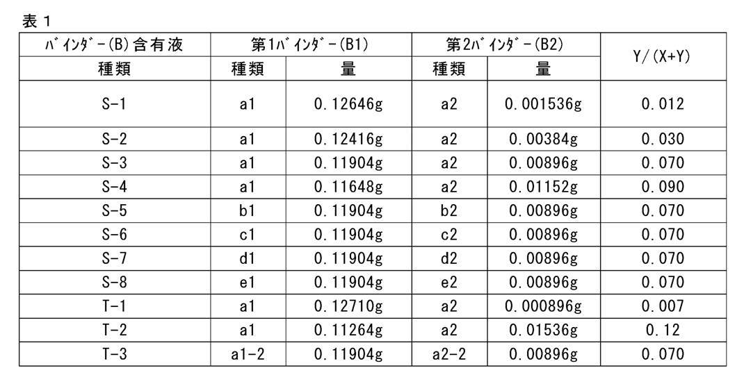
ジルコニア製45mL容器(フリッチュ社製)に、直径5mmのジルコニアビーズを180個投入し、下表に示す無機固体電解質と、上記で調製したバインダー(B)含有液と、分散媒としてのヘプタンとを投入した後に、フリッチュ社製遊星ボールミルP-7(商品名)に容器をセットし、室温下、回転数300rpmで2時間混合して固体電解質組成物を調製した。
また、固体電解質組成物が導電助剤を含有する場合は、上記無機固体電解質と、上記で調製したバインダー(B)含有液と、導電助剤と、分散媒としてのヘプタンとを合わせてボールミルP-7により混合し、固体電解質組成物を調製した。
なお、固体電解質組成物が活物質を含有する場合は、活物質を投入してさらに室温下、回転数150rpmで5分間混合し、固体電解質組成物を調製した。 Preparation Example 1 Preparation of Solid Electrolyte Composition Into a 45 mL container made of zirconia (180 pieces of zirconia beads having a diameter of 5 mm) was charged, and the inorganic solid electrolyte shown in the table below and the binder prepared above (B) After charging the liquid containing and heptane as a dispersion medium, set the container in Fritsch's Planetary ball mill P-7 (trade name) and mix at a rotational speed of 300 rpm for 2 hours at room temperature to obtain a solid electrolyte composition. Prepared.
When the solid electrolyte composition contains a conductive aid, ball mill P is combined with the inorganic solid electrolyte, the binder (B) -containing liquid prepared above, a conductive aid, and heptane as a dispersion medium. The solid electrolyte composition was prepared by mixing according to -7.
When the solid electrolyte composition contained an active material, the active material was charged, and the mixture was further mixed for 5 minutes at a rotation speed of 150 rpm at room temperature to prepare a solid electrolyte composition.
上記で調製した各固体電解質組成物を、集電体である厚み20μmのステンレス鋼(SUS)箔上にバーコーダーにより塗工した。SUS箔を下面としてホットプレート上に設置し、80℃で1時間加熱して分散媒を揮発させて除去し(この除去によっても、分散媒の一部は残留溶媒として残留する)、さらに300MPaで加圧プレスして、固体電解質含有シートを作製した。 Preparation Example 2 Preparation of Solid Electrolyte-Containing Sheet Each solid electrolyte composition prepared above was coated on a 20 μm-thick stainless steel (SUS) foil as a current collector by a bar coder. Place the SUS foil on the hot plate as the lower surface, heat at 80 ° C for 1 hour to volatilize and remove the dispersion medium (even by this removal, part of the dispersion medium remains as a residual solvent), and further at 300 MPa It pressure-pressed and produced the solid electrolyte containing sheet.
上記調製例2で得た各固体電解質含有シートを3cm×5cmの長方形に切り出した。切り出したシートを、長軸方向には端から順に0.5cm、1.5cm、2.5cm、3.5cm、4.5cmの各距離で区切り、短軸方向には端から順に0.5cm、1.5cm、2.5cmの各距離で区切り、長軸方向と短軸方向の各区切りの交点におけるシートの厚さを測定した。測定には、定圧厚さ測定器(テフロック社製、PG-02J)を用いた。得られた15点の厚さのうち、最大値と最小値の差を求め、求めた値を下記評価基準に当てはめ、層厚均一性を評価した。 Test Example 1 Evaluation of Layer Thickness Uniformity Each solid electrolyte-containing sheet obtained in the above Preparation Example 2 was cut into a rectangle of 3 cm × 5 cm. The cut sheet is divided into 0.5 cm, 1.5 cm, 2.5 cm, 3.5 cm, and 4.5 cm distances sequentially from the end in the major axis direction, and 0.5 cm in order from the end in the minor axis direction. The thickness of the sheet at the intersection of each of the major axis direction and the minor axis direction was measured. For measurement, a constant pressure thickness measuring device (PG-FJ, manufactured by TEFLOCK CORPORATION) was used. Among the obtained 15 points of thickness, the difference between the maximum value and the minimum value was determined, and the determined value was applied to the following evaluation criteria to evaluate the layer thickness uniformity.
A:最大層厚と最小層厚の差が5μm未満
B:最大層厚と最小層厚の差が5μm以上、10μm未満
C:最大層厚と最小層厚の差が10μm以上、15μm未満
D:最大層厚と最小層厚の差が15μm以上、20μm未満
E:最大層厚と最小層厚の差が20μm以上、25μm未満
F:最大層厚と最小層厚の差が25μm以上、30μm未満
G:最大層厚と最小層厚の差が30μm以上
結果を下表に示す。 <Evaluation standard of layer thickness uniformity>
A: The difference between the maximum layer thickness and the minimum layer thickness is less than 5 μm B: The difference between the maximum layer thickness and the minimum layer thickness is 5 μm or more and less than 10 μm C: The difference between the maximum layer thickness and the minimum layer thickness is 10 μm or more and less than 15 μm D: The difference between the maximum layer thickness and the minimum layer thickness is 15 μm or more and less than 20 μm E: The difference between the maximum layer thickness and the minimum layer thickness is 20 μm or more and less than 25 μm F: The difference between the maximum layer thickness and the minimum layer thickness is 25 μm or more and less than 30 μm G : The difference between the maximum layer thickness and the minimum layer thickness is 30 μm or more. The results are shown in the table below.
上記調製例2で得た各固体電解質含有シートを直径14.5mmの円板状に2枚切り出した。切り出した2枚のシートの固体電解質層(活物質を含む場合には電極層)を貼り合わせてイオン伝導度測定用シートとし、スペーサーとワッシャー(図2に示していない。)を組み込んで、ステンレス製の2032型コインケース11に入れた。2032型コインケース11をかしめることで、8ニュートン(N)の力で締め付けられた、図2に示す構成のイオン伝導度測定用試験体を作製した。
上記で得たイオン伝導度測定用試験体を用いて、イオン伝導度を測定した。具体的には、30℃の恒温槽中、1255B FREQUENCY RESPONSE ANALYZER(商品名、SOLARTRON社製)を用いて、電圧振幅5mV、周波数1MHz~1Hzまで交流インピーダンス測定した。これにより、貼り合わせた固体電解質含有シート(イオン伝導度測定用シート)の膜厚方向の抵抗を求め、下記式(1)により計算して、イオン伝導度を求めた。得られたイオン伝導度を下記評価基準に当てはめ、評価した。
イオン伝導度σ(mS/cm)=1000×試料膜厚(cm)/(抵抗(Ω)×試料面積(cm2))・・・式(1)
式(1)において、試料膜厚は固体電解質層又は電極層の厚さを意味する。 Test Example 2 Ion Conductivity Each solid electrolyte-containing sheet obtained in the above Preparation Example 2 was cut into a disk shape having a diameter of 14.5 mm. The solid electrolyte layer (electrode layer in the case of including the active material) of the two sheets cut out is pasted together to form a sheet for measuring ionic conductivity, and a spacer and a washer (not shown in FIG. 2) are incorporated to make stainless steel. It was placed in a made 2032
The ion conductivity was measured using the test body for ion conductivity measurement obtained above. Specifically, the alternating current impedance was measured at a voltage amplitude of 5 mV and a frequency of 1 MHz to 1 Hz using a 1255 B FREQUENCY RESPONSE ANALYZER (trade name, manufactured by SOLARTRON) in a 30 ° C. constant temperature bath. Thereby, the resistance of the film thickness direction of the bonded solid electrolyte containing sheet (sheet for measuring ionic conductivity) was determined, and the ionic conductivity was determined by calculation according to the following formula (1). The obtained ion conductivity was applied to the following evaluation criteria and evaluated.
Ion conductivity σ (mS / cm) = 1000 × sample film thickness (cm) / (resistance (Ω) × sample area (cm 2 )) (1)
In formula (1), the sample film thickness means the thickness of the solid electrolyte layer or the electrode layer.
A:0.60≦σ
B:0.50≦σ<0.60
C:0.40≦σ<0.50
D:0.30≦σ<0.40
E:0.20≦σ<0.30
F:σ<0.20
結果を下表に示す。
なお、下表に示す組成は、調製例1で得た固体電解質組成物の組成(質量基準)である。 <Evaluation criteria of ion conductivity>
A: 0.60 ≦ σ
B: 0.50 ≦ σ <0.60
C: 0.40 ≦ σ <0.50
D: 0.30 ≦ σ <0.40
E: 0.20 ≦ σ <0.30
F: σ <0.20
The results are shown in the table below.
The compositions shown in the following table are the compositions (based on mass) of the solid electrolyte composition obtained in Preparation Example 1.

(A):無機固体電解質
LLT:Li0.33La0.55TiO3(平均粒径3.25μm豊島製作所製)
Li-P-S:上記で合成したLi-P-S系ガラス
(D):活物質
NMC:LiNi1/3Co1/3Mn1/3O2(ニッケルマンガンコバルト酸リチウム)
NCA:LiNi0.85Co0.10Al0.05O2(ニッケルコバルトアルミニウム酸リチウム)
(E):導電助剤
AB:アセチレンブラック
VGCF:商品名、昭和電工社製カーボンナノファイバー <Note on table>
(A): Inorganic solid electrolyte LLT: Li 0.33 La 0.55 TiO 3 (average particle size 3.25 μm manufactured by Toshima Seisakusho)
Li-P-S: Li-P-S-based glass synthesized above (D): active material NMC: LiNi 1/3 Co 1/3 Mn 1/3 O 2 (lithium manganese manganese cobalt oxide)
NCA: LiNi 0.85 Co 0.10 Al 0.05 O 2 (lithium nickel cobalt aluminum oxide)
(E): conductive aid AB: acetylene black VGCF: trade name, Showa Denko carbon nanofiber
ここで、バインダーT-3含有液は、バインダーB-1混合液を超遠心で分離する際の超遠心条件が本発明の規定と異なる。この超遠心によってバインダーB-1混合液を処理した際に生じる沈降成分の量は、本発明で規定する超遠心分離条件でバインダー混合液B-1を処理した場合の沈降成分の量と、見た目には変わらず、上澄み成分の透明感も変わらなかった。しかし、上記表2に示すように評価結果は劣っていた。つまり、本発明の効果を奏するためには、本発明で規定する特定の超遠心分離処理によりバインダーを2つの物性のものに分けて、各バインダーの配合量を特定比とすることが重要であることがわかる。
これに対し、固体電解質組成物に含まれるバインダー(B)の成分組成が本発明の規定を満たす場合には、この組成物を用いて形成した固体電解質含有シートは、いずれも層厚のばらつきが小さく、また、イオン伝導度にも優れていた(No.11~27)。 As shown in Table 2 above, when the component composition of the binder (B) contained in the solid electrolyte composition does not satisfy the definition of the present invention, the solid electrolyte-containing sheet formed using this composition has any effect. There was also a large variation in layer thickness. In addition, these solid electrolyte-containing sheets were inferior in ion conductivity (No. c11 to c15).
Here, the binder T-3 containing liquid is different from the definition of the present invention in the ultracentrifugation conditions when the binder B-1 mixed liquid is separated by the ultracentrifugation. The amount of precipitated components produced when the binder B-1 mixed solution is treated by this ultracentrifugation is the amount of precipitated components when the binder mixed solution B-1 is treated under the ultracentrifugation conditions defined in the present invention, and the appearance The clearness of the supernatant component was not changed either. However, as shown in Table 2 above, the evaluation results were inferior. That is, in order to exert the effects of the present invention, it is important to divide the binder into two physical properties by the specific ultracentrifugation treatment specified in the present invention, and to set the blending amount of each binder to a specific ratio I understand that.
On the other hand, when the component composition of the binder (B) contained in the solid electrolyte composition satisfies the definition of the present invention, the thickness of the solid electrolyte-containing sheet formed using this composition varies in all cases. It was small and excellent in ion conductivity (No. 11 to 27).
2 負極活物質層
3 固体電解質層
4 正極活物質層
5 正極集電体
6 作動部位
10 全固体二次電池
11 2032型コインケース
12 全固体二次電池用電極シート
13 全固体二次電池 DESCRIPTION OF SYMBOLS 1 negative electrode
Claims (16)
- 周期律表第一族若しくは第二族に属する金属のイオンの伝導性を有する無機固体電解質(A)と、バインダー(B)と、分散媒(C)とを含む固体電解質組成物であって、
前記バインダー(B)は、前記分散媒(C)中で温度25℃、遠心力610000Gで1時間の遠心分離処理に付した場合に沈降する第1バインダー(B1)と、前記遠心分離処理に付しても沈降しない第2バインダー(B2)とを含み、
前記第1バインダー(B1)の含有量Xと前記第2バインダー(B2)の含有量Yが、質量基準で下記式を満たす、固体電解質組成物。
0.01≦Y/(X+Y)<0.10 A solid electrolyte composition comprising an inorganic solid electrolyte (A) having conductivity of an ion of a metal belonging to Periodic Table Group 1 or Group 2, a binder (B), and a dispersion medium (C),
The binder (B) is added to the first binder (B1) which precipitates when it is subjected to centrifugation at a temperature of 25 ° C. and a centrifugal force of 610000 G for 1 hour in the dispersion medium (C); And a second binder (B2) which does not settle,
The solid electrolyte composition in which content X of said 1st binder (B1) and content Y of said 2nd binder (B2) satisfy | fill the following formula on a mass reference.
0.01 ≦ Y / (X + Y) <0.10 - 前記分散媒(C)が有機溶媒である、請求項1記載の固体電解質組成物。 The solid electrolyte composition according to claim 1, wherein the dispersion medium (C) is an organic solvent.
- 前記第1バインダー(B1)が粒子状バインダーである、請求項1又は2記載の固体電解質組成物。 The solid electrolyte composition according to claim 1, wherein the first binder (B1) is a particulate binder.
- 前記バインダー(B)を構成するポリマーが、ポリアルキレンオキサイド鎖を有する構成成分を含むポリマーを含む、請求項1~3のいずれか1項記載の固体電解質組成物。 The solid electrolyte composition according to any one of claims 1 to 3, wherein the polymer constituting the binder (B) comprises a polymer containing a component having a polyalkylene oxide chain.
- 前記バインダー(B)を構成するポリマーが、ニトリル基を有する構成成分を含むポリマーを含む、請求項1~4のいずれか1項記載の固体電解質組成物。 The solid electrolyte composition according to any one of claims 1 to 4, wherein the polymer constituting the binder (B) comprises a polymer containing a component having a nitrile group.
- 前記分散媒(C)が炭化水素溶媒を含む、請求項1~5のいずれか1項記載の固体電解質組成物。 The solid electrolyte composition according to any one of claims 1 to 5, wherein the dispersion medium (C) contains a hydrocarbon solvent.
- 活物質(D)をさらに含有する、請求項1~6のいずれか1項記載の固体電解質組成物。 The solid electrolyte composition according to any one of claims 1 to 6, further comprising an active material (D).
- 導電助剤(E)をさらに含有する、請求項1~7のいずれか1項記載の固体電解質組成物。 The solid electrolyte composition according to any one of claims 1 to 7, further comprising a conductive aid (E).
- 前記無機固体電解質(A)が硫化物系無機固体電解質である、請求項1~8のいずれか1項記載の固体電解質組成物。 The solid electrolyte composition according to any one of claims 1 to 8, wherein the inorganic solid electrolyte (A) is a sulfide-based inorganic solid electrolyte.
- 請求項1~9のいずれか1項記載の固体電解質組成物を用いて形成した固体電解質含有シート。 A solid electrolyte-containing sheet formed using the solid electrolyte composition according to any one of claims 1 to 9.
- 周期律表第一族若しくは第二族に属する金属のイオンの伝導性を有する無機固体電解質(A)と、バインダー(B)と、溶媒(C1)とを含む固体電解質含有シートであって、
前記バインダー(B)は、前記溶媒(C1)中で温度25℃、遠心力610000Gで1時間の遠心分離処理に付した場合に沈降する第1バインダー(B1)と、前記遠心分離処理に付しても沈降しない第2バインダー(B2)とを含み、
前記第1バインダー(B1)の含有量Xと前記第2バインダー(B2)の含有量Yが、質量基準で下記式を満たす、固体電解質含有シート。
0.01≦Y/(X+Y)<0.10 A solid electrolyte-containing sheet comprising an inorganic solid electrolyte (A) having conductivity of an ion of a metal belonging to periodic group 1 group or group 2, a binder (B), and a solvent (C1),
The binder (B) is subjected to the centrifugal separation treatment with a first binder (B1) which precipitates when it is subjected to centrifugal treatment at a temperature of 25 ° C. and a centrifugal force of 610000 G for 1 hour in the solvent (C1). And a second binder (B2) which does not settle,
A solid electrolyte containing sheet, wherein a content X of the first binder (B1) and a content Y of the second binder (B2) satisfy the following formula on a mass basis.
0.01 ≦ Y / (X + Y) <0.10 - 請求項10又は11記載の固体電解質含有シートを含む、全固体二次電池用電極シート。 An electrode sheet for an all solid secondary battery, comprising the solid electrolyte containing sheet according to claim 10 or 11.
- 正極活物質層と、負極活物質層と、前記正極活物質層及び前記負極活物質層の間の固体電解質層とを含む全固体二次電池であって、
前記正極活物質層、前記負極活物質層及び前記固体電解質層の少なくとも1層が、請求項10又は11記載の固体電解質含有シートで構成された全固体二次電池。 An all solid secondary battery comprising a positive electrode active material layer, a negative electrode active material layer, and a solid electrolyte layer between the positive electrode active material layer and the negative electrode active material layer,
The all-solid-state secondary battery in which at least one layer of the said positive electrode active material layer, the said negative electrode active material layer, and the said solid electrolyte layer was comprised by the solid electrolyte containing sheet | seat of Claim 10 or 11. - 請求項1~9のいずれか1項記載の固体電解質組成物を基材上に塗布して塗布膜を形成する工程を含む、固体電解質含有シートの製造方法。 A method for producing a solid electrolyte-containing sheet, comprising the step of applying the solid electrolyte composition according to any one of claims 1 to 9 on a substrate to form a coating film.
- 前記塗布膜を乾燥する工程を含む、請求項14記載の固体電解質含有シートの製造方法。 The manufacturing method of the solid electrolyte containing sheet | seat of Claim 14 including the process of drying the said coating film.
- 請求項14又は15記載の固体電解質含有シートの製造方法を含む全固体二次電池の製造方法。 The manufacturing method of the all-solid-state secondary battery containing the manufacturing method of the solid electrolyte containing sheet | seat of Claim 14 or 15.
Priority Applications (5)
| Application Number | Priority Date | Filing Date | Title |
|---|---|---|---|
| EP18879439.0A EP3712903A4 (en) | 2017-11-17 | 2018-10-09 | Solid electrolyte composition, solid-electrolyte-containing sheet, all-solid-state secondary battery, production method for solid-electrolyte-containing sheet, and production method for all-solid-state secondary battery |
| CN201880066553.3A CN111213213B (en) | 2017-11-17 | 2018-10-09 | Solid electrolyte composition, solid electrolyte-containing sheet, all-solid-state secondary battery, and method for producing solid electrolyte-containing sheet and all-solid-state secondary battery |
| KR1020207009934A KR102403532B1 (en) | 2017-11-17 | 2018-10-09 | Solid electrolyte composition, solid electrolyte-containing sheet and all-solid secondary battery, and manufacturing method of solid electrolyte-containing sheet and all-solid secondary battery |
| JP2019553746A JP7059302B2 (en) | 2017-11-17 | 2018-10-09 | A method for producing a solid electrolyte composition, a solid electrolyte-containing sheet and an all-solid-state secondary battery, and a solid electrolyte-containing sheet and an all-solid-state secondary battery. |
| US16/843,907 US11552331B2 (en) | 2017-11-17 | 2020-04-09 | Solid electrolyte composition, solid electrolyte-containing sheet, all-solid state secondary battery, method of manufacturing solid electrolyte-containing sheet, and method of manufacturing all-solid state secondary |
Applications Claiming Priority (2)
| Application Number | Priority Date | Filing Date | Title |
|---|---|---|---|
| JP2017221843 | 2017-11-17 | ||
| JP2017-221843 | 2017-11-17 |
Related Child Applications (1)
| Application Number | Title | Priority Date | Filing Date |
|---|---|---|---|
| US16/843,907 Continuation US11552331B2 (en) | 2017-11-17 | 2020-04-09 | Solid electrolyte composition, solid electrolyte-containing sheet, all-solid state secondary battery, method of manufacturing solid electrolyte-containing sheet, and method of manufacturing all-solid state secondary |
Publications (1)
| Publication Number | Publication Date |
|---|---|
| WO2019097903A1 true WO2019097903A1 (en) | 2019-05-23 |
Family
ID=66540163
Family Applications (1)
| Application Number | Title | Priority Date | Filing Date |
|---|---|---|---|
| PCT/JP2018/037617 WO2019097903A1 (en) | 2017-11-17 | 2018-10-09 | Solid electrolyte composition, solid-electrolyte-containing sheet, all-solid-state secondary battery, production method for solid-electrolyte-containing sheet, and production method for all-solid-state secondary battery |
Country Status (6)
| Country | Link |
|---|---|
| US (1) | US11552331B2 (en) |
| EP (1) | EP3712903A4 (en) |
| JP (1) | JP7059302B2 (en) |
| KR (1) | KR102403532B1 (en) |
| CN (1) | CN111213213B (en) |
| WO (1) | WO2019097903A1 (en) |
Cited By (4)
| Publication number | Priority date | Publication date | Assignee | Title |
|---|---|---|---|---|
| WO2020241691A1 (en) * | 2019-05-28 | 2020-12-03 | 株式会社クレハ | All-solid-state battery and method for producing same |
| WO2021014852A1 (en) * | 2019-07-19 | 2021-01-28 | 富士フイルム株式会社 | Inorganic solid electrolyte-containing composition, sheet for all-solid-state secondary batteries, electrode sheet for all-solid-state secondary batteries, all-solid-state secondary battery, method for producing sheet for all-solid-state secondary batteries and method for producing all-solid-state secondary battery |
| JPWO2021200497A1 (en) * | 2020-03-31 | 2021-10-07 | ||
| WO2022124160A1 (en) * | 2020-12-11 | 2022-06-16 | 株式会社豊田自動織機 | Electrode for power storage device and method for manufacturing same |
Citations (5)
| Publication number | Priority date | Publication date | Assignee | Title |
|---|---|---|---|---|
| JP2013008611A (en) * | 2011-06-27 | 2013-01-10 | Nippon Zeon Co Ltd | All-solid type secondary battery |
| JP2015088486A (en) | 2013-09-25 | 2015-05-07 | 富士フイルム株式会社 | Solid electrolytic composition, electrode sheet for batteries arranged by use thereof, and all-solid type secondary battery |
| WO2016152262A1 (en) * | 2015-03-25 | 2016-09-29 | 日本ゼオン株式会社 | All-solid secondary battery |
| WO2017088486A1 (en) | 2015-11-27 | 2017-06-01 | 惠州Tcl移动通信有限公司 | Method and system for giving reminder by mobile terminal |
| WO2017213156A1 (en) * | 2016-06-09 | 2017-12-14 | 日本ゼオン株式会社 | Binder composition for solid electrolyte batteries and slurry composition for solid electrolyte batteries |
Family Cites Families (13)
| Publication number | Priority date | Publication date | Assignee | Title |
|---|---|---|---|---|
| JP5987828B2 (en) * | 2011-06-17 | 2016-09-07 | 日本ゼオン株式会社 | All solid state secondary battery |
| US20150132643A1 (en) * | 2012-04-23 | 2015-05-14 | Zeon Corporation | Lithium ion secondary battery |
| JP6058783B2 (en) * | 2013-03-05 | 2017-01-11 | 協立化学産業株式会社 | Battery electrode or separator coating film composition, battery electrode or separator having a coating film obtained by using the same, and battery having this battery electrode or separator |
| JP5935820B2 (en) * | 2013-04-19 | 2016-06-15 | 東洋インキScホールディングス株式会社 | Conductive composition, current collector with base layer for power storage device, electrode for power storage device, and power storage device |
| JP6110823B2 (en) * | 2013-09-25 | 2017-04-05 | 富士フイルム株式会社 | Solid electrolyte composition, binder for all-solid secondary battery, battery electrode sheet and all-solid-state secondary battery using the same |
| JP6262503B2 (en) * | 2013-11-26 | 2018-01-17 | 三星電子株式会社Samsung Electronics Co.,Ltd. | All-solid secondary battery and method for producing all-solid secondary battery |
| US20150147660A1 (en) * | 2013-11-26 | 2015-05-28 | Samsung Electronics Co., Ltd. | All solid secondary battery and method of preparing all solid secondary battery |
| WO2015099021A1 (en) * | 2013-12-27 | 2015-07-02 | 日本合成化学工業株式会社 | Binder composition for electrode of lithium ion secondary cell, electrode of lithium ion secondary cell, and lithium ion secondary cell |
| JP6059743B2 (en) * | 2014-02-17 | 2017-01-11 | 富士フイルム株式会社 | Solid electrolyte composition, battery electrode sheet and all-solid secondary battery using the same, and method for producing the same |
| JP6475317B2 (en) * | 2015-02-27 | 2019-02-27 | 富士フイルム株式会社 | SOLID ELECTROLYTE COMPOSITION, BATTERY ELECTRODE SHEET AND METHOD FOR MANUFACTURING SAME |
| CN107615554B (en) | 2015-09-16 | 2021-03-30 | 日本瑞翁株式会社 | All-solid-state secondary battery |
| KR101774683B1 (en) * | 2016-01-26 | 2017-09-19 | 현대자동차주식회사 | Electorde active material slurry, preparation method thereof, and all solid secondary battery comprising the same |
| KR102168055B1 (en) | 2016-05-23 | 2020-10-20 | 후지필름 가부시키가이샤 | Solid electrolyte composition, electrode sheet for all-solid secondary battery, and method of manufacturing all-solid secondary battery and electrode sheet for all-solid secondary battery and all-solid secondary battery |
-
2018
- 2018-10-09 WO PCT/JP2018/037617 patent/WO2019097903A1/en unknown
- 2018-10-09 KR KR1020207009934A patent/KR102403532B1/en active IP Right Grant
- 2018-10-09 EP EP18879439.0A patent/EP3712903A4/en active Pending
- 2018-10-09 JP JP2019553746A patent/JP7059302B2/en active Active
- 2018-10-09 CN CN201880066553.3A patent/CN111213213B/en active Active
-
2020
- 2020-04-09 US US16/843,907 patent/US11552331B2/en active Active
Patent Citations (5)
| Publication number | Priority date | Publication date | Assignee | Title |
|---|---|---|---|---|
| JP2013008611A (en) * | 2011-06-27 | 2013-01-10 | Nippon Zeon Co Ltd | All-solid type secondary battery |
| JP2015088486A (en) | 2013-09-25 | 2015-05-07 | 富士フイルム株式会社 | Solid electrolytic composition, electrode sheet for batteries arranged by use thereof, and all-solid type secondary battery |
| WO2016152262A1 (en) * | 2015-03-25 | 2016-09-29 | 日本ゼオン株式会社 | All-solid secondary battery |
| WO2017088486A1 (en) | 2015-11-27 | 2017-06-01 | 惠州Tcl移动通信有限公司 | Method and system for giving reminder by mobile terminal |
| WO2017213156A1 (en) * | 2016-06-09 | 2017-12-14 | 日本ゼオン株式会社 | Binder composition for solid electrolyte batteries and slurry composition for solid electrolyte batteries |
Non-Patent Citations (3)
| Title |
|---|
| A. HAYASHIS. HAMAH. MORIMOTOM. TATSUMISAGOT. MINAMI, CHEM. LETT., 2001, pages 872 - 873 |
| See also references of EP3712903A4 |
| T. OHTOMOA. HAYASHIM. TATSUMISAGOY TSUCHIDAS. HAMGAK. KAWAMOTO, JOURNAL OF POWER SOURCES, vol. 233, 2013, pages 231 - 235 |
Cited By (12)
| Publication number | Priority date | Publication date | Assignee | Title |
|---|---|---|---|---|
| WO2020241691A1 (en) * | 2019-05-28 | 2020-12-03 | 株式会社クレハ | All-solid-state battery and method for producing same |
| JP2020194706A (en) * | 2019-05-28 | 2020-12-03 | トヨタ自動車株式会社 | All-solid battery and manufacturing method thereof |
| JP7364359B2 (en) | 2019-05-28 | 2023-10-18 | トヨタ自動車株式会社 | All-solid-state battery and its manufacturing method |
| WO2021014852A1 (en) * | 2019-07-19 | 2021-01-28 | 富士フイルム株式会社 | Inorganic solid electrolyte-containing composition, sheet for all-solid-state secondary batteries, electrode sheet for all-solid-state secondary batteries, all-solid-state secondary battery, method for producing sheet for all-solid-state secondary batteries and method for producing all-solid-state secondary battery |
| JPWO2021014852A1 (en) * | 2019-07-19 | 2021-01-28 | ||
| CN114144918A (en) * | 2019-07-19 | 2022-03-04 | 富士胶片株式会社 | Composition containing inorganic solid electrolyte, sheet for all-solid-state secondary battery, electrode sheet for all-solid-state secondary battery, sheet for all-solid-state secondary battery, and method for producing all-solid-state secondary battery |
| EP4002514A4 (en) * | 2019-07-19 | 2022-12-28 | FUJIFILM Corporation | Inorganic solid electrolyte-containing composition, sheet for all-solid-state secondary batteries, electrode sheet for all-solid-state secondary batteries, all-solid-state secondary battery, method for producing sheet for all-solid-state secondary batteries and method for producing all-solid-state secondary battery |
| JP7320062B2 (en) | 2019-07-19 | 2023-08-02 | 富士フイルム株式会社 | Composition containing inorganic solid electrolyte, sheet for all-solid secondary battery, electrode sheet for all-solid secondary battery and all-solid secondary battery, and method for producing sheet for all-solid secondary battery and all-solid secondary battery |
| JPWO2021200497A1 (en) * | 2020-03-31 | 2021-10-07 | ||
| WO2021200497A1 (en) * | 2020-03-31 | 2021-10-07 | 富士フイルム株式会社 | Inorganic solid electrolyte-containing composition, sheet for all-solid-state secondary battery, all-solid-state secondary battery, method for producing sheet for all-solid-state secondary battery, and method for producing all-solid-state secondary battery |
| JP7295336B2 (en) | 2020-03-31 | 2023-06-20 | 富士フイルム株式会社 | Composition containing inorganic solid electrolyte, sheet for all-solid secondary battery, all-solid secondary battery, and method for producing sheet for all-solid secondary battery and all-solid secondary battery |
| WO2022124160A1 (en) * | 2020-12-11 | 2022-06-16 | 株式会社豊田自動織機 | Electrode for power storage device and method for manufacturing same |
Also Published As
| Publication number | Publication date |
|---|---|
| JPWO2019097903A1 (en) | 2020-10-22 |
| JP7059302B2 (en) | 2022-04-25 |
| KR102403532B1 (en) | 2022-05-30 |
| CN111213213B (en) | 2021-11-12 |
| EP3712903A1 (en) | 2020-09-23 |
| EP3712903A4 (en) | 2020-12-30 |
| KR20200047679A (en) | 2020-05-07 |
| CN111213213A (en) | 2020-05-29 |
| US20200235426A1 (en) | 2020-07-23 |
| US11552331B2 (en) | 2023-01-10 |
Similar Documents
| Publication | Publication Date | Title |
|---|---|---|
| US11552332B2 (en) | Solid electrolyte composition, solid electrolyte-containing sheet, electrode sheet for all-solid state secondary battery, all-solid state secondary battery, method of manufacturing solid electrolyte-containing sheet, and method of manufacturing all-solid state secondary battery | |
| KR20180093091A (en) | SOLID ELECTROLYTE COMPOSITION, ELECTRODE SHEET FOR PRE-SOLID SECONDARY BATTERY AND PRE-SOLID SECONDARY BATTERY, AND ELECTRODE SHEET FOR PRE-SOLID SECONDARY BATTERY AND METHOD FOR MANUFACTURING PRE-SOLID SECONDARY BATTERY | |
| US20200227751A1 (en) | Solid electrolyte composition, solid electrolyte-containing sheet, all-solid state secondary battery, method of manufacturing solid electrolyte-containing sheet, and method of manufacturing all-solid state secondary battery | |
| JPWO2019098009A1 (en) | A method for producing a solid electrolyte composition, an all-solid-state secondary battery sheet, an all-solid-state secondary battery electrode sheet and an all-solid-state secondary battery, and an all-solid-state secondary battery sheet and an all-solid-state secondary battery. | |
| US11552331B2 (en) | Solid electrolyte composition, solid electrolyte-containing sheet, all-solid state secondary battery, method of manufacturing solid electrolyte-containing sheet, and method of manufacturing all-solid state secondary | |
| JP6572063B2 (en) | All-solid-state secondary battery, electrode sheet for all-solid-state secondary battery, and production method thereof | |
| JP7165747B2 (en) | Electrode composition, electrode sheet for all-solid secondary battery, all-solid secondary battery, and method for producing electrode composition, electrode sheet for all-solid secondary battery, and all-solid secondary battery | |
| WO2020022205A1 (en) | Solid electrolyte composition, solid electrolyte-containing sheet, all-solid secondary battery electrode sheet, all-solid secondary battery, methods for producing solid electrolyte-containing sheet and all-solid secondary battery, and method for producing particulate binder | |
| KR102425881B1 (en) | Solid electrolyte composition and method for manufacturing same, sheet containing solid electrolyte, electrode sheet for all-solid secondary battery, and method for manufacturing all-solid secondary battery | |
| WO2018163976A1 (en) | Solid electrolyte-containing sheet, solid electrolyte composition, all-solid-state secondary battery, method for producing solid electrolyte-containing sheet, and method for producing all-solid-state secondary battery | |
| KR20200039741A (en) | Solid electrolyte composition, solid electrolyte-containing sheet and all-solid secondary battery, and solid electrolyte-containing sheet and all-solid secondary battery manufacturing method | |
| WO2020059550A1 (en) | Production method for all-solid secondary battery layered member, and production method for all-solid secondary battery | |
| US11658282B2 (en) | Composition for forming active material layer and method for manufacturing the same, and methods for manufacturing electrode sheet for all-solid state secondary battery and all-solid state secondary battery | |
| JP6665343B2 (en) | Inorganic solid electrolyte material, and slurry using the same, solid electrolyte membrane for all solid secondary battery, solid electrolyte sheet for all solid secondary battery, positive electrode active material membrane for all solid secondary battery, for all solid secondary battery Negative electrode active material film, electrode sheet for all-solid secondary battery, all-solid secondary battery, and method for manufacturing all-solid secondary battery | |
| WO2020067108A1 (en) | Composition for negative electrodes of all-solid-state secondary batteries, negative electrode sheet for all-solid-state secondary batteries, all-solid-state secondary battery, method for producing negative electrode sheet for all-solid-state secondary batteries, and method for producing all-solid-state secondary battery | |
| WO2019203334A1 (en) | Solid electrolyte composition, all-solid secondary battery sheet, all-solid secondary battery, and method of manufacturing all-solid secondary battery sheet or all-solid secondary battery | |
| WO2019098008A1 (en) | Solid electrolyte composition, all-solid-state secondary battery sheet, all-solid-state secondary battery electrode sheet, all-solid-state secondary battery, production method for all-solid-state secondary battery sheet, and production method for all-solid-state secondary battery | |
| JP6673785B2 (en) | Solid electrolyte composition, solid electrolyte-containing sheet and all-solid secondary battery, and method for producing solid electrolyte-containing sheet and all-solid secondary battery |
Legal Events
| Date | Code | Title | Description |
|---|---|---|---|
| 121 | Ep: the epo has been informed by wipo that ep was designated in this application |
Ref document number: 18879439 Country of ref document: EP Kind code of ref document: A1 |
|
| ENP | Entry into the national phase |
Ref document number: 2019553746 Country of ref document: JP Kind code of ref document: A |
|
| ENP | Entry into the national phase |
Ref document number: 20207009934 Country of ref document: KR Kind code of ref document: A |
|
| NENP | Non-entry into the national phase |
Ref country code: DE |
|
| ENP | Entry into the national phase |
Ref document number: 2018879439 Country of ref document: EP Effective date: 20200617 |